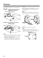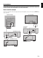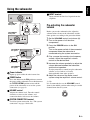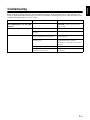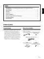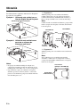
1
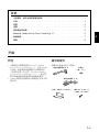
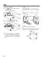
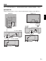
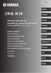
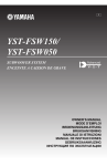
RTL
YST-FSW150/
YST-FSW050
SUBWOOFER SYSTEM
OWNER’S MANUAL
MANUAL DE INSTRUCCIONES
Thank you for selecting this Yamaha subwoofer system.
CAUTION: Read this before operating your unit.
Please read the following operating precautions before use.
Yamaha will not be held responsible for any damage and/or injury
caused by not following the cautions below.
1 To assure the finest performance, please read this manual
carefully. Keep it in a safe place for future reference.
2 Install this unit in a cool, dry, clean place - away from
windows, heat sources, sources of excessive vibration, dust,
moisture and cold. Avoid sources of humming (transformers,
motors).
3 Never open the cabinet. If something drops into the set, contact
your dealer.
4 The voltage to be used must be the same as that specified on
the rear panel. Using this unit with a higher voltage than
specified is dangerous and may cause a fire and/or electric
shock.
5 To reduce the risk or fire or electric shock, do not expose this
unit to rain or moisture.
6 Do not use force on switches, controls or connection wires.
When moving the unit, first disconnect the power plug and the
wires connected to other equipments. Never pull the wires
themselves.
7 When not planning to use this unit for a long period (i.e.,
vacation, etc.), disconnect the AC power plug from the wall
outlet.
8 Since this unit has a built-in power amplifier, heat will radiate
from the bottom panel. Place the unit apart from the walls to
prevent fire or damage. Allow ventilation space of at least 10
cm on the top, 20 cm on the left and right, and 20 cm on the
back of this unit.
9 Do not cover this unit with a newspaper, a tablecloth, a curtain,
etc. in order not to obstruct heat radiation. If the temperature
inside the unit rises, it may cause fire, damage to the unit and/
or personal injury.
10 Do not place the following objects on this unit:
- Glass, china, small metallic etc.
If glass etc. falls by vibrations and breaks, it may cause bodily
injury.
- A burning candle etc.
If the candle falls by vibrations, it may cause fire and bodily
injury.
- A vessel with water in it
If the vessel falls by vibrations and water spills, it may cause
damage to the speaker, and/or you may get an electric shock.
11 Do not place this unit where foreign objects such as water drips
might fall. It might cause a fire, damage to this unit, and/or
personal injury.
12 Never put a hand or a foreign object into the YST port located
on the front side of this unit. When moving this unit, do not
hold the port as it might cause personal injury and/or damage
to this unit.
13 Never place a fragile object near the YST port of this unit. If
the object falls or drops by the air pressure, it may cause
damage to the unit and/or personal injury.
14 Never open the cabinet. It might cause an electric shock since
this unit uses a high voltage. It might also cause personal injury
and/or damage to this unit.
i En
15 When using a humidifier, be sure to avoid condensation inside
this unit by allowing enough spaces around this unit or
avoiding excess humidification. Condensation might cause a
fire, damage to this unit, and/or electric shock.
16 Super-bass frequencies reproduced by this unit may cause a
turntable to generate a howling sound. In such a case, move
this unit away from the turntable.
17 This unit may be damaged if certain sounds are continuously
output at high volume level. For example, if 20 Hz-50 Hz sine
waves from a test disc, bass sounds from electronic
instruments, etc. are continuously output, or when the stylus of
a turntable touches the surface of a disc, reduce the volume
level to prevent this unit from being damaged.
18 If you hear distorted noise (i.e., unnatural, intermittent
“rapping” or “hammering” sounds) coming from this unit,
reduce the volume level. Extremely loud playing of a movie
soundtrack’s low frequency, bass-heavy sounds or similarly
loud popular music passages can damage this speaker system.
19 Vibration generated by super-bass frequencies may distort
images on a TV. In such a case, move this unit away from the
TV set.
20 Do not attempt to clean this unit with chemical solvents as this
might damage the finish. Use a clean, dry cloth.
21 Be sure to read the “Troubleshooting” section regarding
common operating errors before concluding that the unit is
faulty.
22 Install this unit near the wall outlet and where the AC power
plug can be reached easily.
23 VOLTAGE SELECTOR
(For Asia and General models)
The voltage selector switch on the bottom panel of this unit
must be set for your local main voltage BEFORE plugging this
unit into the AC main supply. Voltages are:
110–120/220–240 V AC, 50/60 Hz.
24 Secure placement or installation is the owner’s
responsibility. Yamaha shall not be liable for any accident
caused by improper placement or installation of speakers.
This unit features a magnetically shielded design, but
there is still a chance that placing it too close to a TV set
might impair picture color. Should this happen, move
this unit away from the TV set.
This unit is not disconnected from the AC power source
as long as it is connected to the wall outlet, even if this
unit itself is turned off. In this state, this unit is designed
to consume a very small quantity of power.
English
Table of contents
CAUTION: Read this before operating your unit. . . . . . . . . . . . . . . . . . . . . . . . . . . . . . i
Getting started . . . . . . . . . . . . . . . . . . . . . . . . . . . . . . . . . . . . . . . . . . . . . . . . . . . . 1
Placement . . . . . . . . . . . . . . . . . . . . . . . . . . . . . . . . . . . . . . . . . . . . . . . . . . . . . . . 2
Connections . . . . . . . . . . . . . . . . . . . . . . . . . . . . . . . . . . . . . . . . . . . . . . . . . . . . . . 3
Using the subwoofer . . . . . . . . . . . . . . . . . . . . . . . . . . . . . . . . . . . . . . . . . . . . . . . . 5
Advanced Yamaha Active Servo Technology II . . . . . . . . . . . . . . . . . . . . . . . . . . . . . . 6
Troubleshooting . . . . . . . . . . . . . . . . . . . . . . . . . . . . . . . . . . . . . . . . . . . . . . . . . . . 7
Specifications . . . . . . . . . . . . . . . . . . . . . . . . . . . . . . . . . . . . . . . . . . . . . . . . . . . . 8
Getting started
Features
Supplied accessories
• This subwoofer system employs Advanced
Yamaha Active Servo Technology II, which
Yamaha has developed to reproduce higher
quality super-bass sound (see “Advanced
Yamaha Active Servo Technology II” on page 6
for details). This super-bass sound adds a more
realistic, theater-in-the-home effect to your
stereo system.
• Yamaha’s unique and compact design let you
place this unit horizontally.
Please confirm that the following items are
included in the package.
Subwoofer cable (5 m)
Non-skid pad
(1 set, 4 pieces)
System control cable (5 m)
Stand (YST-FSW150 only)
Screw
(M4, 16 mm) x 2
(YST-FSW150 only)
1 En
Placement
The following illustrations are the setting images
of this unit.
Example 1: Using this unit with Yamaha
Digital Sound Projector
Yamaha Digital Sound Projector
y Tip
You can also place this unit vertically.
When you want to do so, fix a stand using the supplied
screws (YST-FSW150 only) and then attach pads as
shown below.
Note
When placing this unit vertically, set the bottom side
(that the feet are attached to) of this unit toward a wall.
This unit
YST-FSW050
YST-FSW150
Foot
Upsidedown OK
Example 2: As a part of multi channel
speaker system
This unit
Upsidedown OK
y Tip
You can also place this unit in a TV rack etc.
Note
If vibrations of this unit cause abnormal noise or
sympathetic vibrations on nearby components, attach the
supplied non-skid pads to the bottoms of the feet.
Bottom view
(example: YST-FSW150)
Notes
• Do not place this unit on/under any other components
in a pile. The vibration of this unit may cause system
failure, etc. in other components.
• Keep enough ventilation space on the front, the rear,
and the bottom side (that the feet are attached to) of
this unit. Do not place this unit on a thick carpet etc.
2 En
Non-skid
pads
Caution: Do not plug the power cables of the subwoofer and other audio/video components
into an AC outlet until you complete all the other connections.
Basic connection example
Connect the subwoofer cable to the output jack of your AV amplifier, receiver or TV and to the INPUT jack
of the subwoofer.
Flat TV (example)
Amplifier (example)
SUBWOOFER
SUBWOOFER
YST-FSW150
rear panel
INPUT
SYSTEM
CONNECTOR
YST-FSW150 rear panel
INPUT
INPUT
SYSTEM
CONNECTOR
INPUT
SYSTEM
CONNECTOR
INPUT
YST-FSW050 rear panel
YST-FSW050 rear panel
SYSTEM
CONNECTOR
INPUT
3 En
English
Connections
The system connection
This unit has a SYSTEM CONNECTOR jack.
Use the supplied system control cable when
connecting a Yamaha component equipped
with a system connector jack. When
connected, the power mode (ON, OFF/
SYSTEM) of this unit can be controlled with
the power button of the connected Yamaha
component.
Connecting the components and the
subwoofer to the AC power
After you complete a subwoofer connection, plug
the amplifier, TV and/or other audio/video
components, and the subwoofer into an AC outlet
of appropriate voltage.
YST-FSW150 rear panel
Notes
INPUT
• Set the POWER button of this unit to OFF/
SYSTEM. The power of this unit can be turned
on even when the POWER button is set to
OFF/SYSTEM.
• When the POWER button of this unit is set to
ON, the connected component will not control
the power mode of this unit, even though they
are connected via a system connection. The
power mode of this unit will always be ON.
• When this unit does not output low frequency
signals even if you use the system connection,
you need to change the setting of the connected
component. For details, refer to the manual of
the component.
SYSTEM
CONNECTOR
To AC outlet
YST-FSW050 rear panel
SYSTEM
CONNECTOR
INPUT
To AC outlet
Yamaha Digital Sound Projector (example)
VOLTAGE SELECTOR
SYSTEM
CONNECTOR
YST-FSW150 rear panel
(For Asia and General models only)
The voltage selector switch on the bottom panel of this
unit must be set for your local main voltage BEFORE
plugging this unit into the AC main supply.
Voltages are 110–120/220–240 V AC, 50/60 Hz.
VOLTAGE
SELECTOR
INPUT
SYSTEM
CONNECTOR
SYSTEM
CONNECTOR
SYSTEM
CONNECTOR
INPUT
YST-FSW050 rear panel
4 En
220V-240V
110V-120V
English
Using the subwoofer
5 INPUT terminal
POWER
OFF/SYSTEM
YST-FSW150
front panel
1
YST-FSW050
front panel
POWER
0
10
2
3
POWER
VOLUME
OFF/SYSTEM
OFF/SYSTEM
Input terminal for line level signals from the
amplifier.
VOLUME
ON
ON
0
10
0
Before you use the subwoofer, first adjust the
volume balance between the subwoofer and the
front speakers according to the procedure below.
1. Set the VOLUME control to minimum (0).
2. Turn on the power of all the other
VOLUME
ON
Pre-adjusting the subwoofer
volume
10
components.
3. Press the POWER button to the ON
5 INPUT
YST-FSW150
rear panel
INPUT
SYSTEM
CONNECTOR
position.
Turn on the power switch of the connected
component when the subwoofer is
connected using the system connection.
4. Play a source that contains low-frequency
4
sounds. Adjust the amplifier’s volume
control to the desired level.
SYSTEM
CONNECTOR
SYSTEM
CONNECTOR
INPUT
YST-FSW050
rear panel
1 Power indicator
Lights up green while the unit is turned on.
2 POWER button
Press this button to the ON position to turn on
the power of the subwoofer. Press this button to
the OFF/SYSTEM position to turn off the
power of the subwoofer or to use the system
connection (see page 4).
3 VOLUME control
Adjusts the volume level. Turn the control
clockwise to increase the volume, and
counterclockwise to decrease the volume.
5. Increase the volume gradually to adjust the
volume balance between the subwoofer
and the front speakers.
To enjoy natural bass sound, keep the subwoofer
volume at a level where it is barely
distinguishable from other speakers.
6. Adjust the volume of the entire sound
system using the amplifier’s volume control.
y Tip
It is recommended to set the VOLUME control
about in the middle position when using in a multi
channel home theater system.
VOLUME
0
10
4 SYSTEM CONNECTOR terminal
Used for system connection. See “The system
connection” on page 4 for details.
5 En
Advanced Yamaha Active Servo Technology II
In 1998, Yamaha brought to the marketplace
speaker systems utilizing YST (Yamaha Active
Servo Technology) to give powerful, high quality
bass reproduction. This technique uses a direct
connection between the amplifier and speaker,
allowing accurate signal transmission and precise
speaker control.
As this technology uses speaker units controlled by
the negative impedance drive of the amplifier and
resonance generated between the speaker cabinet
volume and port, it creates more resonant energy
(the “air woofer” concept) than the standard bass
reflex method. This allows for bass reproduction
from much smaller cabinets than was previously
possible.
Yamaha’s newly developed Advanced YST II, with
many refinements to Yamaha Active Servo
Technology, allows better control of the forces
driving the amplifier and speakers. From the
amplifier’s point of view, the speaker impedance
changes depending on the sound frequency.
Yamaha developed a new circuit design combining
negative-impedance and constant-current drives,
which provides a more stable performance and
clear bass reproduction with less murkiness.
Cabinet
High-amplitude
bass sound
Air woofer
(Helmholtz resonator)
Port
Signals
Active Servo Processing
Amplifier
Advanced
impedance
Converter
Signals of low
amplitude
6 En
Refer to the chart below if the unit does not function properly. If the problem you are experiencing is not
listed, or if the instructions fail to help you resolve the problem, disconnect the power cable and contact your
authorized Yamaha dealer or service center.
Problem
Cause
Power is not supplied even though
the POWER button is set to the ON
position.
The power plug is not securely connected.
Turn the POWER button to OFF/
SYSTEM, and then connect the power
plug securely.
No sound.
The VOLUME control is set to (0).
Turn up the volume.
A subwoofer cable is not connected
securely.
Connect a subwoofer cable securely.
You are playing a sound source that
includes inadequate bass frequencies.
Play a sound source that includes more
bass frequencies.
The sound level has been diminished by
standing waves.
Reposition the subwoofer, or break up the
parallel wall surface by placing
bookshelves or other large objects along
the wall.
The input signal is too small.
Turn up the volume.
No signal from the subwoofer output
terminal of the component.
Check the speaker mode setting on the
component.
Sound level is too low.
Remedy
7 En
English
Troubleshooting
Specifications
Type ....... Advanced Yamaha Active Servo Technology II
Driver ..............................................16 cm (6-5/16”)
Magnetically shielded type
Output Power
YST-FSW150 ................. 75 W (5 Ω, 10% T.H.D.)
YST-FSW050 ................. 50 W (5 Ω, 10% T.H.D.)
Frequency characteristics
YST-FSW150
100 dB
90
Dynamic Power
YST-FSW150 .................................... 130 W, 5 Ω
YST-FSW050 .................................... 100 W, 5 Ω
80
Input Impedance ...............................................12 kΩ
60
Frequency Response
YST-FSW150 ............................. 30 Hz – 160 Hz
YST-FSW050 ............................. 35 Hz – 160 Hz
70
50
40
20
Input Sensitivity
YST-FSW150 ............ 100 mV (50 Hz, 75 W/5 Ω)
YST-FSW050 .............. 50 mV (50 Hz, 50 W/5 Ω)
Power Supply
[U.S.A. and Canada models]..... AC 120 V, 60 Hz
[Australia model] ....................... AC 240 V, 50 Hz
[China model]............................ AC 220 V, 50 Hz
[Korea model]............................ AC 220 V, 60 Hz
[U.K. and Europe models] ......... AC 230 V, 50 Hz
[Asia and General models]
...................... AC 110–120/220–240 V, 50/60 Hz
Power Consumption
YST-FSW150 ..............................................70 W
YST-FSW050 ..............................................40 W
Dimensions (W x H x D)
YST-FSW150 ........435 mm x 151 mm x 350 mm
(17-2/16 in x 5-15/16 in x 13-12/16 in)
YST-FSW050 ........350 mm x 163 mm x 350 mm
(13-12/16 in x 6-7/16 in x 13-12/16 in)
Weight
YST-FSW150 ....................9.4 kg (20 lbs. 12 oz.)
YST-FSW050 ....................8.5 kg (18 lbs. 12 oz.)
Specifications are subject to change without notice.
8 En
50
100
200
500 Hz
Frequency response graph*
YST-FSW050
100 dB
90
80
70
60
50
40
20
50
100
200
500 Hz
Frequency response graph*
*This diagram does not depict actual frequency
response characteristics accurately.
Gracias por haber seleccionado un sistema de altavoces de ultragraves Yamaha.
PRECAUCIÓN: Leer este manual de instrucciones antes
de poner la unidad en funcionamiento.
Lea las siguientes precauciones de funcionamiento antes de iniciar
el uso del aparato. Yamaha no se responsabilizará de cualquier
daño y/o lesión causada por no seguir las precauciones que
aparecen a continuación.
1 Lea cuidadosamente este manual para obtener el mejor
rendimiento posible. Manténgalo en un lugar seguro para
utilizarlo como referencia en el futuro.
2 Instale esta unidad en un lugar fresco, seco y limpio, alejado de
las ventanas, aparatos que produzcan calor, lugares con
muchas vibraciones, polvo, humedad y frío. Evite aparatos que
causen ruidos de zumbido (transformadores y motores).
3 No abrá nunca la carcasa. Si algo cae en el equipo, póngase en
contacto con su distribuidor.
4 El voltaje a utilizar debe de ser el mismo que el especificado
en el panel trasero. La utilización de esta unidad con un voltaje
superior al especificado puede causar un incendio y/o un a
descarga eléctrica.
5 Para reducir el riesgo de incendio y descarga eléctrica, no
exponga esta unidad a la lluvia o a la humedad.
6 No fuerce los interruptores, controles o cables de conexión.
Cuando mueva esta unidad, desconecte primero el cable de
alimentación y los cables conectados a otros equipos. No tire
nunca de los cables en sí.
7 Cuando no se va a usar el aparato por un largo tiempo (ej.
vacaciones, etc.) desconecte el enchufe de alimentación de CA
del tomacorriente.
8 Este sistema irradia calor por el panel inferior debido a que
tiene un amplificador de potencia incorporado. Coloque la
unidad separada de las paredes, dejando unos 10 cm de espacio
en la parte superior y unos 20 cm en ambos lados y en la parte
posterior, para evitar así un incendio o cualquier otro tipo de
daño.
9 No cubra esta unidad con papel de periódico, un mantel, una
cortina, etc. para no obstruir la radiación de calor. Si aumenta
la temperatura en el interior de la unidad, podrían originarse un
incendio, daños a la unidad y/o lesiones personales.
10 No coloque los siguientes objetos sobre esta unidad:
- Vidrio, porcelanana, pequeños trozos de metal etc.
Si el vidrio, etc. se cae debido a las vibraciones y se romple,
podría causar lesiones personales.
- Un candelabro encendido, etc.
Si el candelabro cae debido a las vibraciones, podría
provocar un incendio y lesiones personales.
- Un jarrón con agua en su interior
Si el jarrón cae debido a las vibraciones y el agua se derrama,
podría causar daños en el altavoz, y/o una descarga eléctrica.
11 No coloque esta unidad donde puedan caer objetos extraños,
como agua derramada. Podría provocar un incendio, daños a
esta unidad y/o daños personales.
12 Nunca ponga las manos o un objeto extraño en el puerto YST,
situado en la parte delantera de esta unidad. Al mover esta
unidad, no sujete el puerto, ya que podría provocar lesiones
personales y/o daños a esta unidad.
13 Nunca coloque un objeto frágil cerca del puerto YST de esta
unidad. Si el objeto cae o se vuelca debido a la presión del aire,
podría provocar lesiones en la unidad y/o lesiones personales.
i Es
14 No abrá nunca la carcasa. Podría provocar una descarga
eléctrica, ya que esta unidad necesita una tensión alta. También
podría provocar lesiones personales y/o daños a esta unidad.
15 Cuando utilice un humidificador, asegúrese de evitar la
condensación dentro esta unidad dejando suficiente espacio
alrededor de esta unidad o evitando el exceso de
humidificación. La condensación podría causar un incendio,
daños a esta unidad, y/o descarga eléctrica.
16 Las frecuencias de ultragraves generadas por esta unidad
pueden hacer que el tocadiscos emita un sonido de aullidos. En
este caso, alejar la unidad del tocadiscos.
17 La unidad podría ser dañada, si se escucharan continuamente
ciertos sonidos en el nivel máximo de volumen. Por ejemplo,
si se escuchan ondas sinusoidales de 20 Hz-50 Hz con el disco
de prueba, sonidos graves de instrumentos electrónicos, etc.; o
cuando la aguja del tocadiscos toque la superficie de un disco,
reduzca el nivel de volumen para evitar que se dañe el equipo.
18 Si se escuchan sonidos distorsionados (ej. sonidos raros,
“golpeteos” o “martilleos” intermitentes) provenientes de la
unidad, baje el nivel del volumen. Si se reproducen con el
volumen alto pistas de sonido de películas de baja frecuencia,
sonidos con bajos fuertes o música de similares características
se podría dañar el sistema de altavoces.
19 La vibración generada por frecuencias ultragraves podría
distorsionar las imágenes de una TV. En este caso, alejar el
sistema del televisor.
20 No intente limpiar esta unidad con disolventes químicos, ya
que podrían dañar el acabado. Utilice para la limpieza un paño
limpio y seco.
21 No deje de leer la seeción “Solucionar problemas”, donde se
dan consejos sobre los errores de utilización antes de llegar a
la conclusión de que la unidad está averiada.
22 Instale esta unidad cerca de la toma de CA, donde se pueda
llegar fácilmente a la clavija de alimentación de CA.
23 VOLTAGE SELECTOR
(Modelos de Asia y Generale solamente)
El selector VOLTAGE SELECTOR del panel inferior de este
aparato deberá ponerse en la posición correspondiente a la
tensión empleada en su localidad ANTES de conectar el
aparato a la red de alimentación de CA. Las tensiones son:
CA 110–120/220–240 V, 50/60 Hz
24 La instalación en un lugar seguro es responsabilidad del
propietario. Yamaha no se hace responsable por ningún accidente
provocado por una instalación incorrecta de los altavoces.
Esta unidad dispone de un diseño a prueba de
interferencias magnéticas, aunque existe la posibilidad
de que, en el caso de colocarlo demasiado cerca de un
aparato de TV, el color de la imagen pueda verse
afectado. En este caso, aleje el sistema del televisor.
Esta unidad no se desconecta de la fuente de
alimentación de CA si está conectada a una toma de
corriente, aunque la propia unidad esté apagada. En este
estado, esta unidad ha sido diseñada para que consuma
una cantidad de corriente muy pequeña.
Índice
Español
PRECAUCIÓN: Leer este manual de instrucciones antes de poner la unidad en
funcionamiento. . . . . . . . . . . . . . . . . . . . . . . . . . . . . . . . . . . . . . . . . . . . . . . . . . . . i
Primeros pasos . . . . . . . . . . . . . . . . . . . . . . . . . . . . . . . . . . . . . . . . . . . . . . . . . . . 1
Ubicación . . . . . . . . . . . . . . . . . . . . . . . . . . . . . . . . . . . . . . . . . . . . . . . . . . . . . . . 2
Conexiones . . . . . . . . . . . . . . . . . . . . . . . . . . . . . . . . . . . . . . . . . . . . . . . . . . . . . . 3
Utilizar el subwoofer . . . . . . . . . . . . . . . . . . . . . . . . . . . . . . . . . . . . . . . . . . . . . . . . 5
Advanced Yamaha Active Servo Technology II . . . . . . . . . . . . . . . . . . . . . . . . . . . . . . 6
Solucionar problemas . . . . . . . . . . . . . . . . . . . . . . . . . . . . . . . . . . . . . . . . . . . . . . . 7
Especificaciones. . . . . . . . . . . . . . . . . . . . . . . . . . . . . . . . . . . . . . . . . . . . . . . . . . . 8
Primeros pasos
Características
Accesorios incluidos
• Este sistema de subwoofer emplea Advanced
Yamaha Active Servo Technology II que
Yamaha ha desarrollado para reproducir un
sonido supergrave de calidad más alta (vea
“Advanced Yamaha Active Servo Technology
II” en la página 6 para conocer detalles). Este
sonido de supergraves añade un efecto más
realista de cine en el hogar a su sistema estéreo.
• El diseño único y compacto de Yamaha le
permite colocar esta unidad horizontalmente.
Asegúrese de que los siguientes elementos estén incluidos en el paquete.
Cable del Subwoofer (5 m) Almohadilla antideslizante
(1 juego, 4 piezas)
Cable conector del sistema (5 m)
Base
(YST-FSW150 solamente)
Tornillo
(M4, 16 mm) x 2
(YST-FSW150 solamente)
1 Es
Ubicación
Las ilustraciones siguientes muestras las imágenes
de ajuste de esta unidad.
Ejemplo 1: Utilizando esta unidad con un
Yamaha Digital Sound Projector
Yamaha Digital Sound Projector
Esta unidad
y Sugerencia
También puede poner esta unidad verticalmente.
Cuando quiera hacer esto, fije una base usando los
tornillos suministrados (YST-FSW150 solamente) y
luego coloque esterillas como se muestra más abajo.
Nota
Cuando instale esta unidad verticalmente, ponga el lado
inferior (el que tiene las patas colocadas) de la misma
hacia una pared.
YST-FSW050
YST-FSW150
Pata
Ejemplo 2: Utilizando esta unidad como
parte de un sistema de
altavoces multicanal
Esta unidad
Al revés
está bien
Al revés
está bien
y Sugerencia
También puede poner esta unidad en una estantería de
TV, etc.
Nota
Si las vibraciones de esta unidad causan ruidos
anormales o vibraciones en componentes cercanos,
coloque las almohadillas antideslizantes en las partes
inferiores de las patas.
Notas
• No ponga esta unidad en/debajo de ningún otro
componente formando una pila. La vibración de esta
unidad puede causar fallos, etc. en otros componentes.
• Deje suficiente espacio de ventilación en la partes
delantera, posterior e inferior (donde se colocan las
patas) de esta unidad. No ponga esta unidad encima de
una alfombra gruesa, etc.
2 Es
Vista inferior
(ejemplo: YST-FSW150)
Almohadillas
antideslizantes
Conexiones
Precaución: No conecte los cables de alimentación del subwoofer y de otros componentes
de audio/vídeo a una toma de CA hasta después de completar todas las otras conexiones.
Conecte el cable de altavoz de subgraves al jack de salida de su amplificador AV, receptor o TV y al jack
INPUT del altavoz de subgraves.
TV de pantalla plana (ejemplo)
Amplificador (ejemplo)
SUBWOOFER
SUBWOOFER
Panel trasero del
YST-FSW150
INPUT
SYSTEM
CONNECTOR
Panel trasero del YST-FSW150
INPUT
INPUT
SYSTEM
CONNECTOR
INPUT
SYSTEM
CONNECTOR
INPUT
Panel trasero del YST-FSW050
Panel trasero del YST-FSW050
SYSTEM
CONNECTOR
INPUT
3 Es
Español
Ejemplo básico de conexión
La conexión del sistema
Esta unida tiene un jack SYSTEM
CONNECTOR. Use el cable conector del
sistema suministrado cuando conecte un
componente Yamaha equipado con jack de
conector del sistema. Cuando conecte, el
modo de alimentación (ON, OFF/SYSTEM)
de esta unidad podrá controlarse con el botón
de alimentación del componente Yamaha
conectado.
Conectar componentes y el
subwoofer a CA
Después de finalizar una conexión de subwoofer,
conecte el amplificador, el TV y/u otros
componentes de audio/vídeo, y el subwoofer a una
toma de CA de la tensión apropiada.
Panel trasero del YST-FSW150
INPUT
SYSTEM
CONNECTOR
Notas
• Ponga el botón POWER de esta unidad en
OFF/SYSTEM. La alimentación de esta unidad
se puede activar cuando el botón POWER se
pone en OFF/SYSTEM.
• Cuando el botón POWER de esta unidad se
ponga en ON, el componente conectado no
controlará el modo de alimentación de esta
unidad, aunque éstos estén conectados mediante
una conexión del sistema. El modo de
alimentación de esta unidad estará siempre en
ON.
• Cuando esta unidad no dé salida a señales de
baja frecuencia aunque use la conexión del
sistema, necesitará cambiar el ajuste del
componente conectado. Para conocer detalles,
consulte el manual del componente.
Yamaha Digital Sound Projector (ejemplo)
SYSTEM
CONNECTOR
Panel trasero del YST-FSW150
A la toma de CA
Panel trasero del YST-FSW050
SYSTEM
CONNECTOR
INPUT
A la toma de CA
VOLTAGE SELECTOR
(Para los modelos de Asia y General solamente)
El interruptor de selección de tensión situado en el panel
inferior de esta unidad debe ajustarse a la tensión
principal de su emplazamiento ANTES de enchufar esta
unidad a la fuente principal de CA.
La selección de voltajes es para CA de 110–120/
220–240 V, 50/60 Hz.
VOLTAGE
SELECTOR
220V-240V
INPUT
SYSTEM
CONNECTOR
SYSTEM
CONNECTOR
SYSTEM
CONNECTOR
INPUT
Panel trasero del YST-FSW050
4 Es
110V-120V
Utilizar el subwoofer
5 Terminal INPUT
POWER
OFF/SYSTEM
1
Panel delantero
del YST-FSW050
POWER
10
2
3
POWER
VOLUME
OFF/SYSTEM
OFF/SYSTEM
0
ON
0
10
VOLUME
ON
0
Español
Panel delantero
del YST-FSW150
Terminal de entrada para las señales de nivel de
línea del amplificador.
VOLUME
ON
Pre-ajustar el volumen del
subwoofer
Antes de utilizar el subwoofer, primero ajuste el
balance de volumen entre el subwoofer y los
altavoces frontales según el procedimiento a
continuación.
1. Ajuste el control VOLUME al mínimo (0).
2. Conecte la alimentación de todos los
10
demás componentes.
3. Pulse el botón POWER a la posición ON.
5 INPUT
Panel trasero del
YST-FSW150
INPUT
SYSTEM
CONNECTOR
4
Active el interruptor de la alimentación del
componente conectado cuando el
subwoofer esté conectado usando la
conexión del sistema.
4. Reproduzca una fuente que contenga
SYSTEM
CONNECTOR
SYSTEM
CONNECTOR
INPUT
Panel trasero del
YST-FSW050
1 Indicador Power
Se enciende en verde cuando la unidad está en.
2 Botón POWER
Pulse este botón hasta la posición ON para
conectar la alimentación del subwoofer. Pulse
este botón hasta la posición OFF/SYSTEM
para desconectar la alimentación del subwoofer
o para usar la conexión del sistema (vea la
página 4).
3 Control VOLUME
Ajusta el nivel de volumen. Gire el control en
sentido horario para aumentar el volumen y en
sentido antihorario para reducirlo.
4 Terminal SYSTEM CONNECTOR
sonidos de baja frecuencia. Ajuste el
control de volumen del amplificador al nivel
deseado.
5. Aumente el volumen gradualmente para
ajustar el balance de volumen entre el
subwoofer y los altavoces frontales.
Para disfrutar de un sonido de bajo natural,
ajuste el nivel del subwoofer en un punto en que
a penas sea distinguible de otros altavoces.
6. Ajuste el volumen de todo el sistema de
sonido utilizando el control de volumen del
amplificador.
y Sugerencia
Es aconsejable ajustar el control VOLUME
aproximadamente a su posición central si utiliza un
sistema home theater multicanal.
VOLUME
0
10
Se usa para la conexión del sistema. Vea “La
conexión del sistema” en la página 4 para
conocer detalles.
5 Es
Advanced Yamaha Active Servo Technology II
reflexión de graves. Esto permite una reproducción
de graves en carcasas mucho más pequeñas de lo
que era posible hasta ahora.
El recientemente desarrollado Advanced YST II de
Yamaha, con muchos refinamientos para Yamaha
Active Servo Technology, permite controlar mejor
las fuerzas que accionan el amplificador y los
altavoces. Desde el punto de vista del amplificador,
la impedancia de los altavoces cambia según la
frecuencia del sonido. Yamaha desarrolló un nuevo
circuito que combina la impedancia negativa y los
accionamientos de corriente constante, lo que
proporciona un rendimiento más estable y una
reproducción de graves más clara.
En 1998, Yamaha puso en el mercado sistemas de
altavoces que utilizaban YST (Yamaha Active
Servo Technology) para reproducir graves potentes
de alta calidad. Esta técnica utiliza una conexión
directa entre el amplificador y el altavoz,
permitiendo una gran precisión en transmisión de
señales y control de altavoces.
Dado que esta tecnología utiliza unidades de
altavoces controlados por el impulso de
impedancia negativa del amplificador y por la
resonancia generada entre el volumen y el puerto
de la carcasa del altavoz, crea una energía
resonante (el concepto de “altavoz de aire para
graves”) superior a la del método estándar de
Mueble
Sonido de bajos
de amplitud alta
Altavoz de graves de aire
(Resonador Helmholtz)
Puerto
Señales
Procesamien to Active
Servo Amplificador
Convertidor de
impedancia
avanzado
Señales de
amplitud baja
6 Es
Solucionar problemas
Consulte la tabla a continuación si la unidad no funciona correctamente. Si el problema que ocurre no
aparece en la lista o si las instrucciones no sirven para resolver el problema, desconecte el cable de
alimentación y contacte con un distribuidor autorizado o con un centro de servicio Yamaha.
Causa
Solución
El conector de la alimentación no está
conectado con firmeza.
Ponga el botón POWER en OFF/
SYSTEM y luego conecte firmemente la
clavija de alimentación.
No hay sonido.
El control VOLUME está ajustado a (0).
Suba el volumen.
Un cable del subwoofer no está conectado
de forma segura.
Conecte un cable del subwoofer de forma
segura.
Está reproduciendo una fuente de sonido
que incluye frecuencias de bajos
inadecuadas.
Reproduzca una fuente de sonido que
incluya más frecuencias de bajos.
El nivel de sonido ha sido reducido por las
ondas flotantes.
Vuelva a situar el subwoofer o divida la
superficie paralela de la pared, colocando
estanterías para libros u otros objetos
grandes en la pared.
La señal de entrada es demasiado
pequeña.
Suba el volumen.
No hay señal procedente del terminal de
salida de altavoz de subgraves del
componente.
Compruebe el ajuste del modo de
altavoces en el componente.
El nivel de sonido es muy bajo.
7 Es
Español
Problema
No se suministra alimentación
aunque el botón POWER esté en la
posición ON.
Especificaciones
Tipo ........ Advanced Yamaha Active Servo Technology II
Bocina .......................................................... 16 cm
Tipo blindado magnéticamente
Potencia de salida
YST-FSW150 .............. 75 W (5 Ω, THD de 10%)
YST-FSW050 .............. 50 W (5 Ω, THD de 10%)
Características de frecuencia
YST-FSW150
100 dB
90
Potencia dinámica
YST-FSW150 .................................... 130 W, 5 Ω
YST-FSW050 .................................... 100 W, 5 Ω
80
Impedancia de entrada.....................................12 kΩ
60
Respuesta de frecuencia
YST-FSW150 ............................. 30 Hz – 160 Hz
YST-FSW050 ............................. 35 Hz – 160 Hz
70
50
40
20
Sensibilidad de entrada
YST-FSW150 ............ 100 mV (50 Hz, 75 W/5 Ω)
YST-FSW050 .............. 50 mV (50 Hz, 50 W/5 Ω)
Alimentación
[Modelos para los EE.UU. y Canadá]
.................................................. CA 120 V, 60 Hz
[Modelo para Australia] ............. CA 240 V, 50 Hz
[Modelo para China].................. CA 220 V, 50 Hz
[Modelo para Corea] ................. CA 220 V, 60 Hz
[Modelos del R.U. y Europa] ..... CA 230 V, 50 Hz
[Modelos de Asia y General]
...................... CA 110–120/220–240 V, 50/60 Hz
50
100
200
500 Hz
Gráfico de respuesta de frecuencia*
YST-FSW050
100 dB
90
80
70
60
Consumo
YST-FSW150 ..............................................70 W
YST-FSW050 ..............................................40 W
50
40
Dimensiones (An x Al x Prof)
YST-FSW150 ........435 mm x 151 mm x 350 mm
YST-FSW050 ........350 mm x 163 mm x 350 mm
Peso
YST-FSW150 ............................................ 9,4 kg
YST-FSW050 ............................................ 8,5 kg
Tenga en cuenta que todas las especificaciones
pueden verse sometidas a cambios sin previo aviso.
8 Es
20
50
100
200
500 Hz
Gráfico de respuesta de frecuencia*
*Este gráfico no muestra de forma precisa las
características de la respuesta de frecuencia real.
感谢您选用 Yamaha 超低音扬声器系统。
注意事项:操作本装置前敬请阅读
请在使用前阅读以下操作需知。对于不遵守以下操作
需知而造成的损坏和 / 或伤害,Yamaha 概不负责。
1 为了确保获得最佳性能,请仔细阅读本使用说明
书,并妥善保管,以备将来参考。
2 请在凉爽、干燥、清洁的地方安装本装置。应远离
窗口、热源,避免在振动过大、灰尘过多、湿气过
重和温度过低的地方使用,以及应远离嗡声声源
(变压器及马达)。
3 切勿开启箱体,如果异物落入本装置内,请与经销商联系。
4 使用的电压必须与后面板上标明的一致。如果使用电压
高于指定电压是危险的,可能会引起火灾和 / 或电击。
5 为了减少火灾或电击的危险,切勿将本装置暴露于
雨水或湿气中。
6 请勿在开关、控制器或连接线上强行施力。移动时,应首
先拔掉电源插头及连接其他设备的接线,请勿拉动接线。
7 如果长期不使用本装置 (如度假等),请从墙壁插
座中拔出交流电源插头。
8 因为本装置带有功率放大器,会通过底面板散热。
应将本装置远离墙壁放置以防火灾或损坏。为了保
证通风良好,应在本装置上面保持最少 10 厘米;
左右最少 20 厘米;背后最少 20 厘米的空间。
9 请勿将报纸,桌布,窗帘等物覆盖在本装置上,以
免妨碍热量散发。
10 请勿将以下物品放置在本装置上:
- 玻璃、陶瓷、小金属片等
如果玻璃等因振动而倒下和打碎,有可能使人体
受到伤害。
- 燃烧的蜡烛等
如果蜡烛因振动而倒下,有可能引起火灾和使人
体受到伤害。
- 装有水的容器
如果容器因振动而倒下或水溢出来,有可能使装
置受到损坏,并引起触电。
11 请勿将本装置放置在有异物例如水滴落下的地方,否
则可能导致火灾,破坏装置和 / 或使人体受到伤害。
12 切勿将手或异物放进位于本机前部的 YST 舱门中。
当移动本机时,不可手抓舱门,否则可能导致人身
伤害和 / 或损坏本机。
10
13 切勿将易碎物体放在 YST 开门附近,如果物体因气压而倒
下或掉落,可能使装置受到破坏和 / 或使人体受到伤害。
14 切勿打开箱体,因为本装置使用了高电压,有可能
造成电击,并使人体受到伤害和 / 或破坏装置。
15 使用加湿器时,要在本机附近留有足够的空间或不
要使湿度过大,以免机器内部结露。结露会造成火
灾,损坏本机和 / 或电击。
16 本装置复制的超低音频率可能使唱盘产生啸声,在
这种情况下,请将本装置远离唱盘放置。
17 如果某一声音以高音量持续输出,可能会损坏本装
置,例如,如果试碟产生 20 Hz 至 50 Hz 正弦波,
电子设备持续输出低音或可转动唱针接触到唱片表
面时,请降低音量,以防止本装置损坏。
18 如果从本装置中听到失真 (如不自然、间断的敲
击或击打声),请降低音量水平。电影声轨的低
频、超低音或类似的流行音乐播放音量过大,可能
会损坏此扬声器系统。
19 超低音频率产生的振动可能令电视机图像失真。在
此情况,请将本机搬离电视机。
20 请勿使用化学溶剂清洁本装置,否则有可能损坏抛
光面。请用清洁的干布擦拭。
21 遇到故障时,请阅读有关常见操作故障的 “故障排除”一节。
22 将本机靠近电源插座安装以便电源的接插。
23 VOLTAGE SELECTOR (仅限于亚洲机型及通用机型)
在插入交流电源之前,必须将本机底面板上的电压选
择开关设定到与当地电源相同的电压。电源电压为:
110-120/220-240 V AC,50/60 Hz
24 用户应自行负责安放或安装。若扬声器因安放或安
装不当而造成事故,Yamaha 公司概不负责。
虽然本机采用磁屏蔽设计,但若摆放位置与电视机
过于接近,则仍可能影响电视的画面色彩。在此情
况下,把本机搬离电视机。
只要本机连接在电源插座上,即使电源开关关闭
时,机器与交流电源的连接也没有切断。在待机
模式下,本机仅消耗微小电力。
该标记附加在出售到中华人民共和国的电子信息产品上。
环形中的数字表示的是环境保护使用期限的年数。
○ : 表示该有毒有害物质在该部件所有均质材料中的含量均在 SJ/T 11363-2006 标准规定的限量要求以下。
× : 表示该有毒有害物质至少在该部件的某一均质材料中的含量超出 SJ/T
11363-2006 标准规定的限量要求。
有毒有害物质或元素
部件名称
铅
(Pb)
汞
(Hg)
镉
(Cd)
六价铬
(Cr(VI))
多溴联苯
(PBB)
多溴二苯醚
(PBDE)
电路板
×
○
○
○
○
○
外壳箱体
×
×
○
○
○
○
○
○
○
○
○
○
扬声器单元
i Zh
目录
注意事项:操作本装置前敬请阅读 . . . . . . . . . . . . . . . . . . . . . i
开始 . . . . . . . . . . . . . . . . . . . . . . . . . . . . . . . . . . 1
放置 . . . . . . . . . . . . . . . . . . . . . . . . . . . . . . . . . . 2
连接 . . . . . . . . . . . . . . . . . . . . . . . . . . . . . . . . . . 3
使用超低音音箱 . . . . . . . . . . . . . . . . . . . . . . . . . . . . . 5
Advanced Yamaha Active Servo Technology II . . . . . . . . . . . . . . . 6
中文
故障排除 . . . . . . . . . . . . . . . . . . . . . . . . . . . . . . . . 7
规格 . . . . . . . . . . . . . . . . . . . . . . . . . . . . . . . . . . 8
开始
特性
提供的配件
• 本超低音音箱系统使用 Advanced Yamaha
Active Servo Technology II,这是 Yamaha
开发的一种再现高质量超低音音响的技术
(详情参见第 6 页上的 “Advanced Yamaha
Active Servo Technology II”)。 能为您
的音响系统添加更逼真的家庭影院效果。
• Yamaha 独特且紧凑的设计使得您可以水平放
置本机。
请确认包装盒内有以下物品。
超低音音箱缆线 (5 m)
防滑垫
(1 套,4 个 )
系统控制缆线 (5 m)
支架 (仅限于 YST-FSW150)
螺钉 (M4, 16 mm) x 2
(仅限于 YST-FSW150)
1 Zh
放置
下面是本机的设置事例图。
例 1: 与 Yamaha Digital Sound Projector
一起使用本机
Yamaha Digital Sound Projector
y 提示
您也可以竖直放置本机。
如果您希望如此放置,可以使用附带的螺钉如下图
所示固定支架 (仅限于 YST-FSW150),然后附加垫
片。
注
本机
当垂直放置本机时,将本机的底面 (安装有支脚)
面向墙壁。
YST-FSW050
YST-FSW150
支脚
可以倒置
例 2: 作为多声道扬声器系统的一部分
可以倒置
本机
y 提示
您也可以放置本机到电视机框架等地点。
注
如果本机的震动引起异常噪音或在附近的其他装置
引起感应震动,请在本机的腿脚底部安装防滑垫。
从底部看
( 例 : YST-FSW150)
注
• 不要将本机置于其他装置之上 / 下堆垛放置。 本
机产生的震动可能引起其他装置的系统失效等。
• 在本机的前后,背部以及底部 (安装支脚的地
方)保持足够的通风空间。不要将本机放置于厚
地毯上。
2 Zh
防滑垫
连接
注意:在完成其他所有连接之前,不能将超低音音箱和其他音频 / 视频设备的电源线插入 AC 插座中。
基本连接示例
将超低音音箱连线连接到 AV 放大器,接收机或电视机的输出接口和超低音音箱的 INPUT 接口。
平板电视 ( 例 )
放大器 ( 例 )
中文
SUBWOOFER
SUBWOOFER
YST-FSW150
后部面板
INPUT
SYSTEM
CONNECTOR
YST-FSW150 后部面板
INPUT
INPUT
SYSTEM
CONNECTOR
INPUT
SYSTEM
CONNECTOR
INPUT
YST-FSW050 后部面板
YST-FSW050 后部面板
SYSTEM
CONNECTOR
INPUT
3 Zh
系统连接
本机具有 SYSTEM CONNECTOR 插孔。 在连
接具有系统连接器的 Yamaha 装置时,请使
用附带的系统控制缆线。 一旦连接,就可
以使用所连接的 Yamaha 装置上的电源按钮
控制本机的电源模式 (ON,OFF/SYSTEM)。
将视听设备和超低音音箱连接到
AC 电源
超低音音箱的连接完成后,连接放大器,电视
机和 / 或其他音频 / 视频装置以及超低音音箱
的电源到妥当电压的交流电源插座。
YST-FSW150 后部面板
注
• 设置本机的 POWER 按钮到 OFF/SYSTEM。 即使
当本机的 POWER 按钮设置到 OFF/SYSTEM 时,
本机的电源也可以开启。
• 当本机的 POWER 按钮设置到 ON 时,即使系统
连接存在,所连接的装置将不控制本机的电
源模式。 本机的电源模式将总是 ON。
• 当本机不输出低频信号时,而您又进行了系
统连接,您必须改变所连接的装置的设置。
详情请参阅该装置的使用说明书。
INPUT
SYSTEM
CONNECTOR
到交流插孔
YST-FSW050 后部面板
Yamaha Digital Sound Projector (例)
SYSTEM
CONNECTOR
INPUT
SYSTEM
CONNECTOR
到交流插孔
YST-FSW150 后部面板
VOLTAGE SELECTOR
INPUT
SYSTEM
CONNECTOR
SYSTEM
CONNECTOR
( 仅限于亚洲和通用型号 )
在您将电源插头插入交流电源之前,必须要根据您
当地的主电压设置本机底部面板上的电源选择开
关。
可选电压为 110-120/220-240 V AC, 50/60 Hz。
VOLTAGE
SELECTOR
220V-240V
SYSTEM
CONNECTOR
INPUT
YST-FSW050 后部面板
4 Zh
110V-120V
使用超低音音箱
5 INPUT 端子
POWER
OFF/SYSTEM
YST-FSW150
前部面板
1
ON
0
POWER
预调节超低音音箱音量
2
3
POWER
VOLUME
OFF/SYSTEM
OFF/SYSTEM
10
ON
0
10
VOLUME
ON
0
10
5 INPUT
YST-FSW150
后部面板
INPUT
在使用超低音音箱之前,首先根据以下步骤,
调节超低音音箱和前音箱的音量平衡。
1. 将 VOLUME 音量控制设置为最小 (0)。
2. 打开所有其他装置的电源。
3. 按下 POWER 按钮到 ON 位置。
中文
YST-FSW050
前部面板
来自放大器的电平位准信号的输入终端。
VOLUME
当超低音音箱处于系统连接状态时,开启所
连接装置的电源开关。
4. 播放包含低频声效的源材料。 调节放大器的
音量控制到期望的水平。
5. 逐渐调高音量,用以调整超低音音箱和前置
音箱的平衡度。
要欣赏自然的低音时,将超低音音箱的音量控制
在一定水平,使其不会被从其他音箱的声音中识
别出来。
SYSTEM
CONNECTOR
4
6. 使用放大器的音量控制器调节整个声音系统
SYSTEM
CONNECTOR
的音量。
SYSTEM
CONNECTOR
INPUT
y 提示
YST-FSW050
后部面板
使用多声道家庭影院系统时,建议您将 VOLUME
控制键设置在中间位置。
VOLUME
1 电源指示器
当本机开启时以绿色点亮。
2 POWER 按钮
0
10
按下此按钮到 ON 位置,开启超低音音箱的
电源。 按下此按钮到 OFF/SYSTEM 位置,关
闭超低音音箱的电源,或者使用系统连接
功能 (请参阅第 4 页)。
3 VOLUME 旋钮
调节音量水平。 顺时针方向旋转增加音量,
而反时针方向旋转减小音量。
4 SYSTEM CONNECTOR 端子
用于系统连接。 有关详情请参阅第 4 页上
的 “系统连接”。
5 Zh
Advanced Yamaha Active Servo Technology II
1998 年,Yamaha 向市场推出了使用 YST
(Yamaha Active Servo Technology) 的音箱,
此技术可以产生强力,高质量的低音再现。 本
技术在放大器和音箱之间采用了直接连接方
式,可实现精密的信号传输和精确的音箱控
制。
由于本技术使用的音箱装置由放大器的负阻抗
驱动和音箱箱与开口间产生的共鸣加以控制,
因此可以比标准的低音反射方法产生更多的共
鸣能量 (“气动低音箱”概念)。 这使得比以
前更小的箱体也能再现低音。
Yamaha 最新研制的 Advanced YST II,对
Yamaha Active Servo Technology 进行了许多
改进,可以对放大器和音箱的驱动力进行更好
的控制。 从放大器的观点看,音箱的阻抗根据
音响的频率而变。 Yamaha 研制出新的电路设
计,结合了负阻抗和恒电流驱动,从而可提供
更稳定的性能以及朦胧更少的清晰的低音再
现。
箱体
高振幅低音
气动低音音箱
(Helmholtz 共呜器)
信号
主动伺服处理放大器
通道
先进的阻抗转化器
低振幅信号
6 Zh
故障排除
如果设备工作不正常,请参考下表中的信息。 如果您遇到的问题没有列在下面,或如果下面给出
的指导不起作用,请断开电源线,并联络 Yamaha 授权的经销商或服务中心。
问题
即使当 POWER 按钮设置到 ON 位置时,
仍然没有电源提供。
无声音。
音量水平太低。
原因
措施
电源插头连接不牢靠。
将 POWER 按钮设置到 OFF/SYSTEM, 牢
固连接电源插头。
调高音量。
将连线紧密连接。
您在播放包含不完全低音频率的声源
材料。
播放包含更多低音频率的声源材料。
音量被驻波削弱。
重新放置超低音音箱,或靠墙边放置
书架或大的物品破坏平行的墙面。
输入信号太小。
调高音量。
没有信号从设备的输出端子到超低音
音箱。
检查该设备上的音箱模式设定。
7 Zh
中文
VOLUME 音量控制设置为 (0)。
超低音音箱连线连接不牢固。
规格
类型... Advanced Yamaha Active Servo Technology II
驱动器 ................................. 16 cm
磁屏蔽类型
输出功率
YST-FSW150........... 75 W (5 Ω, 10% T.H.D.)
YST-FSW050........... 50 W (5 Ω, 10% T.H.D.)
动态功率
YST-FSW150...................... 130 W, 5 Ω
YST-FSW050...................... 100 W, 5 Ω
频率特性
YST-FSW150
100 dB
90
80
70
输入阻抗..................................12 kΩ
60
频率响应
YST-FSW150.................. 30 Hz - 160 Hz
YST-FSW050.................. 35 Hz - 160 Hz
50
输入敏感度
YST-FSW150....... 100 mV (50 Hz,75 W/5 Ω)
YST-FSW050........ 50 mV (50 Hz,50 W/5 Ω)
电源
[ 美国和加拿大型号 ] ....... AC 120 V,60
[ 澳大利亚型号 ] ........... AC 240 V,50
[ 中国型号 ]................ AC 220 V,50
[ 韩国型号 ]................ AC 220 V,60
[ 英国和欧洲型号 ] ......... AC 230 V,50
[ 亚洲和通用型号 ]
............ AC 110-120/220-240 V,50/60
40
20
50
100
200
500 Hz
频率响应图 *
YST-FSW050
100 dB
Hz
Hz
Hz
Hz
Hz
Hz
90
80
70
60
电力消耗
YST-FSW150............................ 70 W
YST-FSW050............................ 40 W
尺寸 (宽 x 高 x 深)
YST-FSW150........ 435 mm x 151 mm x 350 mm
YST-FSW050........ 350 mm x 163 mm x 350 mm
重量
YST-FSW150.......................... 9.4 kg
YST-FSW050.......................... 8.5 kg
规格更改恕不提前通知。
8 Zh
50
40
20
50
100
200
500 Hz
频率响应图 *
*该图并未精确地描述实际的频率相应。
© 2007
YAMAHA ELECTRONICS CORPORATION, USA 6660 ORANGETHORPE AVE., BUENA PARK, CALIF. 90620, U.S.A.
YAMAHA CANADA MUSIC LTD. 135 MILNER AVE., SCARBOROUGH, ONTARIO M1S 3R1, CANADA
YAMAHA ELECTRONIK EUROPA G.m.b.H. SIEMENSSTR. 22-34, 25462 RELLINGEN BEI HAMBURG, GERMANY
YAMAHA ELECTRONIQUE FRANCE S.A. RUE AMBROISE CROIZAT BP70 CROISSY-BEAUBOURG 77312 MARNE-LA-VALLEE CEDEX02, FRANCE
YAMAHA ELECTRONICS (UK) LTD. YAMAHA HOUSE, 200 RICKMANSWORTH ROAD WATFORD, HERTS WD18 7GQ, ENGLAND
YAMAHA SCANDINAVIA A.B. J A WETTERGRENS GATA 1, BOX 30053, 400 43 VÄSTRA FRÖLUNDA, SWEDEN
YAMAHA MUSIC AUSTRALIA PTY, LTD. 17-33 MARKET ST., SOUTH MELBOURNE, 3205 VIC., AUSTRALIA
All rights reserved.
Printed in Indonesia
WM03480