1
BEFORE TO USE THIS SOUND EQUIPMENT IS IMPORTANT
TO READ THIS MANUAL
ANTES DE USAR SU EQUIPO DE SONIDO ES IMPORTANTE
LEER ESTE MANUAL
Owner's manual
Manual de instrucciones
DB179MP
DB279USB
CD/MP3IWMA RECEIVER
RECEPTOR CD/MP3IWMA
CLARION PRODUCT REGISTRATION INFORMATION
www.clarion.com
Dear Customer:
Congratulations on your purchase of a Clarion mobile electronic products. We are confident that
you'll enjoy your Clarion experience.
There are many benefits to registering your product. We invite you to visit our website at www.
clarion.com to register your Clarion product.
We have made product registration simple with our easy to use website. The registration form
is short and easy to complete. Once you're registered, we can keep you informed of important
product information.
Register at www.clarion.com - it's easy to keep your Clarion product up to date.
Contents
2
3
1.
FEATURES
2.
CONTROLS
MAIN UNIT
3
3.
NOMENCLATURE
Names of the Buttons and Their Functions
Display Items
LCD Screen
4
4
5
5
4.
PRECAUTIONS
5.
6.
HANDLING COMPACT DISCS
DCP (Detachable Control Panel)
6
7
8
7.
OPERATIONS
Basic Operations
Radio Mode Operations
CD/MP3/WMA Mode Operations
9
12
13
8.
OTHER OPERATIONS
19
9.
TROUBLESHOOTING
21
9
10. ERROR DISPLAYS
22
11. SPECIFICATIONS
23
,
"
0
'1. FBAJIElBS
• High Visibility Single Line Display
• 2ch/2V RCA Output
• Front Panel 3.5mm Auxiliary Input
• Front Panel USB Input
Note:
Only for the model DB279USB
WDO~~
DIGITAL AUDIO
~
2
Be so," to onfold and ,..d the next
Cerciorese de despJegar y de Jeer la pagina si .
teo
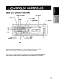
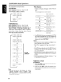
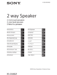
2.CONTROLS/CONTROLES
MAIN UNIT! UNlOAD PRINCIPAL
[CD SLOT]
[DIRECT] [ROM]
[SCN]
I
I
[RPT]
I
..----[SRC]
[ROTARY]
[RELEAS
[~]---:-~
[O]----.;~
[J']----:~
[ISR]-~~
[ON]
Note: Be sure to unfold this page and refer to the front diagrams as you read each chapter.
Nota: Cuando lea los capitulos, despliegue esta pagina y consulte los diagramas.
The functions of your audio equipment to variant according at model acquired with your distributed.
Las funciones de su equipo de audio varian de acuerdo al modelo adquirido con su distribuidor.
3
3. NOMENGLATURE
Note:
Be sure to read this chapter referring to the front diagrams of chapter "2. CONTROLS" on page 3.
•
Names of the Buttons and Their Functions
RELEASE] button
Rress the [RELEASE] button to unlock the
detachable panel.
[~] button
• Eject a CD when it is loaded in the unit.
[0] button
• During Radio mode, switch the display
indication in the following order:
Main Display ~Clock Display ~ Main Display...
• During CD/AUX mode, switch the display
indication (Main Display, Clock Display).
• During MP3IWMA mode, switch the display
indication in the following order:
Track No./Play Time ~ Folder No.lPlay Time
~Track Name ~Folder Name ~Title Tag ~
Album Tag ~ Artist Tag ~ Clock Display ~
Track No.lPlay Time ...
• Press and hold the button for 1 second or
longer to enter the Adjustment mode.
[J'] button
• Use the button to enter to the Sound mode.
(Z-Enhancer, Bass, Treble, Balance, Fader).
• Press and hold for 1 second or longer to turn
on or off the M-B EX mode.
[ISR] button
• Recall ISR radio station in memory.
• Press and hold for 2 seconds or longer: Store
current station into ISR memory (Radio mode
only).
[ROM] button
• Perform random play while in the CD/MP31
WMA mode.
• Press and hold the button for 1 second or
longer to perform all random play while in the
MP3IWMA mode.
[UP], [ON] buttons
• Select the folder (MP3IWMA disc only).
[ ..... ],
[~I]
buttons
• Seek a station while in the Radio mode or
select a track when listening to a CD. These
buttons are used to make various settings.
• Press and hold the button for 1 second or longer
to enter the fast-forward or fast-backward in
CD/MP3IWMA mode.
[ ~ II] button
• Perform preset scan while in the Radio mode.
Press and hold the button for 2 seconds or
longer to perform auto store.
• Play or pause a track while in the CD/MP31
WMA mode.
• Perform second level adjustment or selection.
[SRC] button
• Press the button to turn on the power.
Press and hold the button for 1 second or
longer to turn off the power.
• Switch the Operation mode among the Radio
mode, CD/MP3IWMA mode and AUX mode.
[BND] button
[DIRECT] buttons
• Store a station into memory or recall it directly
while in the Radio mode.
[SCN] button
• Perform scan play for 10 seconds of each track
while in the CD/MP3IWMA mode.
• Press and hold the button for 1 second or
longer to perform all scan play while in the
MP3IWMA mode.
[RPT] button
• Repeat play while in the CD/MP3/WMA mode .
• Press and hold the button for 1 second or
longer to perform all repeat play while in the
MP3/WMA mode.
4
• Switch the band, or seek tuning or manual
tuning while in the Radio mode.
• Play the first track while in the CD/MP3IWMA
mode.
• Press and hold the button for 1 second or
longer to select CD-DA or MP3IWMA on a
Multi-session disc.
[ROTARY] knob
• Adjust the volume by turning the knob clockwise
or counterclockwise.
• Use the knob to perform various settings.
Names of the Buttons and Their Functions
CD SLOT]
[AUX] input
CD insertion slot.
• Auxiliary jack insertion.
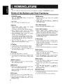
Display Items
Operation status indication
Main Display, Clock, etc. are displays
Preset channel
indication (1 to 6)
: WMA indication
: Z- Enhancer indication
USB
USB indication
mIJ
Enter indication
III
STili: Stereo indication
MANU : Manual indication
VII. : All tracks indication
ROM: Random indication
RPT : Repeat indication
SeN: Scan indication
LCD Screen
In extreme cold, the screen movement may slow down and the screen may darken, but this is normal.
The screen will recover when it returns to normal temperature.
5
4. PRECAUTIONS
1. When the inside of the car is very cold and
the player is used soon after switching on the
heater moisture may form on the disc or the
optical parts of the player and proper playback
may not be possible. If moisture forms on the
disc, wipe it off with a soft cloth. If moisture
forms on the optical parts of the player, do
not use the player for about one hour. The
condensation will disappear naturally allowing
normal operation.
This equipment has been tested and found to
comply with the limits for a Class B digital device,
pursuant to Part 15 of the FCC Rules.
These limits are designed to provide reasonable
protection against harmful interference in a residential installation.
2. Driving on extremely bumpy roads which
cause severe vibration may cause the sound
to skip.
3. This unit uses a precision mechanism.
Even in the event that trouble arises, never
open the case, disassemble the unit, or
lubricate the rotating parts.
USE OF CONTROLS, ADJUSTMENTS,
OR PERFORMANCE OF PROCEDURES
OTHER THAN THOSE SPECIFIED HEREIN,
MAY RESULT IN HAZARDOUS RADIATION
EXPOSURE.
This equipment generates, uses, and can radiate
radio frequency energy and, if not installed and
used in accordance with the instructions, may
cause harmful interference to radio communications. However, there is no guarantee that interference will not occur in a particular installation.
THE COM PACT DISC PLAYER SHOU LD NOT
BE ADJUSTED OR REPAIRED BY ANYONE
EXCEPT PROPERLY QUALIFIED SERVICE
PERSONNEL.
If this equipment does cause harmful interference to radio or television reception, which can
be determined by turning the equipment off and
on, the user is encouraged to consult the dealer
or an experienced radiolTV technician for help.
CHANGES OR MODIFICATIONS TO THIS
6
PRODUCTNOTAPPROVEDBYTHEMAN~
FACTURER WILL VOID THE WARRANTY
AND WILL VIOLATE FCC APPROVAL.
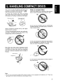
5. HANDLING COMPACT DISCS
This unit has been designed specifically for
playback of compact discs bearing the ru'JO~@
mark. No other discs can be played.
DOG,,,,,",,.
Note on compact discs
Never stick labels on the surface of the compact
disc or mark the surface with a pencil or pen.
To remove the compact disc from its storage
case, press down on the center of the case and
lift the disc out, holding it carefully by the edges.
Removing the disc
Proper way to hold
the compact disc
Always handle the compact disc by the edges.
Never touch the surface.
Do not use any solvents such as commercially
available cleaners, anti-static spray, or thinner to
clean compact discs.
No
To remove fingermarks and dust, use a soft cloth,
and wipe in a straight line from the center of the
compact disc to the circumference.
Do not use compact discs that have large scratches, are misshapen, or cracked. etc. Use of such
discs will cause misoperation or damage.
New discs may have some roughness around
the edges. The unit may not work or the sound
may skip if such discs are used. Use a ball-point
pen, etc. to remove roughness from the edge of
the disc.
Ball-point pen
II
Roughness
Do not expose compact discs to direct sunlight or
any heat source.
Note:
• Do not use commercially available CD protection sheets or discs equipped with stabilizers, etc. These may
get caught in the internal mechanism and damage the disc.
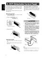
7
The control panel can be detached to prevent
theft. When detaching the control panel, store it
in the DCP (Detachable Control Panel) case to
prevent scratches.
We recommend taking the OCP with you when
leaving the car.
Storing the DCP in the DCP case
Hold the OCP, in the orientation as shown in the
figure below, and put it into the supplied OCP
case. (Ensure the OCP is in the correct orientation .)
Removing the DCP
1. Press the [SRC] button for 1 second or longer
to switch off the power.
.?'
2. Press in the [RELEASE] button.
/
OCP case .._.../
/,... [RELEASE] button
!
~'-~L~l
i~
* The OCP is unlocked
•
The DCP can easily be damaged by impact.
After removing it, be careful not to drop it
or subject it to strong shocks.
•
When the Release button is pressed and
the DCP is unlocked, the car's vibrations
may cause it to fall. To prevent damage to
the DCP, always store it in its case after
detaching it. (See figure above.)
•
The connector connecting the main unit and
the DCP is an extremely important part. Be
careful not to damage it by pressing on it
with fingernails, pens, screwdrivers, etc.
3. Remove the OCP.
Main Unit Front
DCP Rear Panel
Attaching the DCP
1. Insert the right side of the DCP into the main
unit.
2. Insert the left side of the OCP to attach into the
main unit.
Note:
• If the OCP is dirty, wipe off the dirt with a soft. dry
cloth only.
• To remove the front panel OCP. is important that
left side should be lift slightly to avoid stucking.
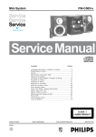
8
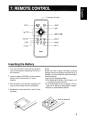
Transmisor de senal
SRC
[SRCJ--+t-~
- 7 f - t t - - - [ BND J
..----f+---- [ ., II J
~-++---[DISpJ
[ MUTE J ---++----ff-e
[ISR]
~-++---[RDMJ
[SCN]
------++---- [ RPT J
Clarion
Inserting the Battery
1. Turn over the remote control until and slide the
cover in the direction indicated by the arrow in
the illustration.
2. Insert the battery (CR2025) into the insertion
guides, with the printed side (+) facing
upwards.
3. Press the battery in the direction indicated by the
arrow so that it slides into the compartmet.
Notes:
Misuse may result in rupture of the battery, producing
leakage of fluid and resulting in personal injury or
damage to surround materials. Always follow these
safety precaution:
• Use only the designate battery.
• When replacing the battery, insert properly, with
+/- polarities oriented correctly.
• Do not subject battery to heat, or dispose of in fire or
water. Do not attempt to disassemble the battery.
• Dispose of used batteries properly.
4. Replace the cover and slide in until it clicks
into place.
9
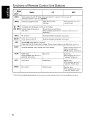
Functions of Remote Control Unit Buttons
~
Radio
MP3
CD
Button
.
[SRC]
Turns power on and off When press and held for 1 second: Turns power off.
Switches between radio and CD/MP3.
[BND]
Switches reception band.
Plays the first track.
Top play.
Plays the first track of the
current folder
---
[! ] , IT ]
O~~], ~]
[~II ]
Increases and decreases volume (in all modes).
No function
._-----Moves tracks up and down.
When pressed and held for 1 second: Fast-forward/fas t backward.
._--------Switches between playback and pause
I
Turns mute on and off.
Switches between playback and pause
Moves preset channels up
and down.
~-_
[MUTE]
[ISR]
.. _."...
_---,.... _." .. I:;
---~l
Recalls ISR radio station in memory
Press and hold for 2 seconds or longer: Stores current station into ISR (radio mode O~~_)_
[DISP]
Switches between main display and clock display.
Switch among main a/spray.
folder number display,
TITLE display, clock display
[SCN]
Preset scan.
When pressed and held for 2
seconds: Auto store.
Scan play.
Scan play.
When pressed and held for
1 second: Folder scan
[RPT]
No function
Repeat play.
Repeat play.
When pressed and held tor
1 second: Folder repeat.
[RDM]
No function
Random play.
Random play.
When pressed and held for
1 second: Folder random
* Some of the corresponding buttons on the main unit and remote control unit have different functions.
10
I
Basic Operations
Note: Be sure to read this chapter referring to the front diagrams of
chapter "2. CONTROLS" on page 3.
Be sure to lower the volume before switching off the unit power or the ignition key. The
unit remembers its last volume setting. If
you switch the power off with the volume up,
when you switch the power back on, the sudden loud volume may hurt your hearing and
damage the unit.
Turning onloff the power
Note:
• Be careful about using this unit for a long time
without running the engine. If you drain the car's
battery too much, you may not be able to start the
engine and this can reduce the service life of the
battery.
1. Press the [SRC] button.
2. The illumination and display on the unit light
up. The unit automatically remembers its last
Operation mode and will automatically switch
to display that mode.
3. Press and hold the [SRC] button for 1 second
or longer to turn off the power for the unit.
Selecting a mode
1. Press the [SRC] button to change the Operation mode.
2. Each time you press the [SRC] button, the Operation mode changes in the following order:
Radio mode ~ CD/MP3IWMA mode
AUX mode ~ Radio mode...
~
Note:
• If the CD mode is selected when no disc is inserted,
the display shows "NO DISC".
• Radio mode
Main Display ~ Clock Display ~ Main Display...
• CD mode
Main Display (Track No., Play Time) ~
Clock Display ~ Main Display...
• MP3IWMA mode
Main-1 Display (Track No., Play Time) ~
Main-2 Display (Folder No., Play Time) ~
Track ~ Folder ~Title ~ Album ~ Artist ~
~ Clock Display ~ Main-1 Display...
• AUX mode
Main Display ~ Clock Display
~
Main Display...
* Once selected, the preferred display becomes the
display default. When a function adjustment such
as volume is made, the screen will momentarily
switch to that function's display, then revert back
to the preferred display several seconds after the
adjustment.
Adjusting the volume
Turning the [ROTARY] knob clockwise increases
the volume; turning it counterclockwise decreases the volume. "VOL XX" will be displayed where
"XX" is the volume level from 0 (minimum) to 33
(maximum).
* The factory
default setting for volume is 'VOL
13".
Sound mode adjustments
1. Press the [J'] button to enter the Sound Adjustment mode.
2. Press the [ ~ , ~~] button to select the
"item name".
"Z-EHCR"
t
Switching the display
"BASS"
Press the [D] button to select the desired display.
Each time you press the [D] button, the display
switches in the following order:
t
"TREBLE"
t
t
"FADER"
"BALANCE"
USB Mode
Main display
~
clock display
~
Main display
Note: This function only apply for model DB279USB
11
Basic Operations
3. Turning the [ROTARY] knob to adjust the
selected Sound mode.
Z-EHCR
Selection type
: OFF
~
B-BOOST
~
IMPACT~EXCITE ~OFF...
BASS
Adjustment range: -7 to +7
TREBLE
Adjustment range : -7 to +7
BALANCE:
Adjustment range: LEFT 12 to RIGHT 12
FADER
Adjustment range: FRONT 12 to REAR 12
Notes:
• If no operation is performed for more than 10 seconds, the Audio mode is cancelled and returns to
the previous mode.
• Bass and Treble can only be adjusted when the
"Z-EHCR" is off.
Setting the Z-Enhancer
This unit is provided with 3 types of sound tone
effects stored in memory. Select the one you prefer.
2-1. Press the [~, ~~I] button and select "ZEHCR".
3-1. Turning the [ROTARY] knob to change to the
following sound tone effect.
"OFF"
t
t
"IMPACT"
t
"B-BOOST"
"EXCITE"
• OFF
: no sound effect
• B-BOOST: b~ emphasized
(€~ indicator lights in the display)
• IMPACT
: ba~s and treble emphasized
(~ indicator lights in the display)
• EXCITE
: bass and treble emphasized mid
de-emphasized
(~) indicator lights in the display)
",,-·oJ
~pr'
Note:
• The factory default setting is "OFF".
12
Adjusting the bass
2-1. Press the [J'] button and select "BASS
with [~, .... ] button.
3-1. Turning the [ROTARY] knob clockwise em
phasizes the bass; turning it counterclock
wise attenuates the bass.
"BASS XX" will be displayed where "XX'· is
the value from -7 to +7.
Note:
• The factory default setting is "BASS 0".
Adjusting the treble
2-1. Press the [J'] button and select "TREBLE",
with [ ~ , .... ] button .
3-1. Turning the [ROTARY] knob clockwise emphasizes the bass; turning it counterclockwise attenuates the bass .
"TREB XX" will be displayed where "XX" is
the value from -7 to +7.
Note:
• The factory default setting is "TREB 0".
Adjusting the balance
2-1. Press the [J' ] button and
select "BALANCE'.
with [ ~ , .... ] button.
3-1. Turning the [ROTARY] knob clockwise emphasizes the sound from the right speaker;
turning it counterclockwise emphasizes the
sound from the left speaker.
The display changes as follows:
"RIGHT XX" will be displayed where "XX" is
the value from 1 to 12.
"LEFT XX" will be displayed where "XX" is
the value from 1 to 12.
Notes:
• When Balance is 0, "CENTER" will be displayed
instead.
• The factory default setting is "CENTER".
Basic Operations
Adjusting the fader
2-1. Press the [J' ] button
and select "FADER".
with [ ..... , ~ ] button.
3-1. Turning the [ROTARY] knob clockwise emphasizes the sound from the front speakers;
turning it counterclockwise emphasizes the
sound from the rear speakers.
Notes:
• Use only the 3.5mm stereo jack for the AUX jack
input.
• Volume can be adjusted through the unit. If you
face difficulties of hearing sound even after volume
has been adjusted, please refer section "Selecting
AUX IN sensitivity" on page 19 for details.
The display changes as follows:
"FRONT XX" will be displayed where "XX" is
the value from 1 to 12.
"REAR XX" will be displayed where "XX" is
the value from 1 to 12.
Notes:
• When Fader is 0, "CENTER' will be displayed
instead .
• The factory default setting is "CENTER".
Adjusting MAGNA BASS EX
The MAGNA BASS EX does not adjust the low
sound area like the normal sound adjustment
function, but emphasizes the deep bass sound
area to provide you with a dynamic sound.
1. Press and hold the [J' ] button for 1 second
or longer to turn on the MAGNA BASS EX effect.
~
M~
indicator lights in the display.
2. Press and hold the [J' ] button for 1 second
or longer to turn off the MAGNA BASS EX effect.
indicator goes off from the display.
Note:
• The factory default setting is "OFF".
AUX function
This system has an external jack input in the front
panel where you can listen to sounds and music
from external devices connected to this unit.
USB Function
This sistem has an external Jack input in the
front panel wehre you can listen to sunds and
music from external devices connected to this
unit.
1. Connect the external music player to the USB
input.
2. Press the SRC buttom and select the USB
mode to activate the USB function.
Note: The function USB apply only for the model
DB279USB
According at your model acquired with your
distributor.
1. Connect the external music player to the [AUX]
input.
2. Press the [SRC] button and select the AUX
mode to activate the AUX function.
13
Radio Mode Operations
Listening to the radio
1. Press the [SRC] button and select the Radio
mode. then the radio will be on.
2. To select a preset band. press the [BND] button, and then select one of the preset bands
such as FM1, FM2, FM3 or AM.
Every time the [BND] button is pressed. the
band switches in the following order:
F1
~
F2
~
F3
~
AM
~
• Step tuning:
Press the [I........... ~~I ] button to perform manual
tuning.
Preset memory function
Preset memory function can store up to 24 stations
Six stations for each of FM 1, Ffvl2, FM3 and AM.
F1 ...
3. Press the [ ,.......... , ~~,] button to tune in the
desired station.
Manual memory function
Seek tuning
2. Press the [,~...... ~~] button to tune Into a
desired station.
1. Press the [BND] button and select the desired
band (FM or AM)
*
If MANU" is lit in the display. oress and hold
the [BND] button for 1 second or longer.
"MANU" in the display goes off and seek tuning
is now available.
2. Press the [,.......... , ~~I] button to start automatic
station tuning.
When the [~~,] button is pressed. search will
be performing in the direction of higher frequencies. When the [,.......... ] button is pressed,
search will be performed in the direction of
lower frequencies
Manual tuning
There are 2 ways available Quick tuning and
step tuning.
When you are in the step Tuning mode. the frequency changes one step at a time. In the quick
Tuning mode. you can quickly tune the desired
frequency.
1. Press the [BND] button and select the desired
band (FM or AM).
"" If "MANU" is not lit in the display. press and hold
the [BND] button for 1 second or longer.
"MANU" is !It in the display and manual tuning
is now available.
2. Tune into a station
•
Quick tuning:
Press and hold the [ ,.......... . ""~I J button for 1 second or longer to begin static·rJ tuni!'Q.
14
1. Press the [BND] button and to select
you want to store in th9 memory.
3.
band
3. Press and hold one of the [DIRECT] buttons for
2 seconds or longer to store the current station
into preset memory.
Auto store
Auto store is a function for storing up to 6 stations
that are automatically tuned in sequentially. If 6
receivable stations cannot be received. a previously stored station remains un-overwritten at
the memory position.
1. Press the [BND] button and select the desired
band (FM or AM).
2. Press and hold the [~ II] button for 2 seconds
or longer. The stations with good reception are
stored automatically to the preset channels
"A-STORE" will be displayed.
Preset scan
Preset scan receives the stations stored in preset
memory in order. This function is useful when
searching for a desired station in memory
1. Press the [~II] button.
2. When a desired station is tuned in, press the
[~II] button again to continue receiving that
station. "P-SCN" will be displayed and "SeN"
indicator lights in the display.
Note:
• Be careful not to press and hold the r ~ IIJ button
for 2 seconds or longer. otherwise the auto store
function is engaged and the unit starts storing stations.
Radio Mode Operations
CD/MP3IWMA Mode
Operations
Recalling a preset station
What is MP3?
A total of 24 preset positions (6-FM1, 6-FM2,
6-FM3, 6-AM) exists to store individual radio
stations in memory. Pressing the correspondD!RECT] button reca!!s the stored radio frequency automatically.
2. Press the corresponding [DIRECT] button to
recall the stored station.
MP3 is an audio compression method and classified into audio layer 3 of MPEG standards. This
audio compression method has penetrated into
PC users and become a standard format. This
MP3 features the original audio data compression to about 12 percent of its initial size with a
high quality sound. This means that about 10
music CDs can be recorded on a CD-R disc or
CD-RW disc to allow a long listening time without
having to change CDs.
Instant station recall (ISR)
What is WMA?
Instant station recall is a special radio preset that
instantly accesses a favorite radio station at a
touch of a button. The ISR function even operates with the unit in other modes.
WMA is the abbreviation of Windows Media Audio, an audio file format developed by Microsoft
Corporation.
1. Press the [BND] button and select the desired
band (FM or AM).
•
ISR memory
1. Select the station that you wish to store in ISR
memory.
2. Press and hold the USR] button for 2 seconds
or longer.
•
Recalling a station with ISR
In any mode, press the [ISR] button to turn on the
radio function and tune the selected radio station. "ISR" appears in the display. Press the USR]
button again to return to the previous mode.
Notes:
• WMA file with DRM (Digital Rights Management)
will be skipped from being playback and jump to
the next track.
• Windows Media TM, and the Windows® logo are
trademarks, or registered trademarks of Microsoft
Corporation in the United States and/or other
countries.
Note:
• Personally constructed WMA files are used at your
own responsibility.
•
Precautions when creating MP3/WMA
disc
•
Usable sampling rates and bit rates:
15
CD/MP3IWMA Mode Operations
MP3
....
Decode Format
Sampling Rate
(kHz)
Bit-rate (kbps)
WMA
•
..
MPEG 1, 2 and 2.5 - Layer 3
MPEG-1 : 32, 44.1, 48
MPEG-2 : 16, 22.05, 24
MPEG-2.5 : 8, 11.025, 12
MPEG-1 : 32 - 320
MPEG-2 : 8 - 160
MPEG-2.5 : 8 - 160
VBR
:
.'
Sampling rate
(kHz)
48,44.1,32
Bit-rate (kbps)
32 - 192
Folder Level Limit
..
... ,.
: 8 Level
Max. Files Support
: 254
Folder Name
: Max. 28 Characters
File Name
: Max. 28 Characters
•
File extensions
•
Always add a file extension ".MP3" or ".WMA"
to MP3 or WMA file by using single characters
letters. If you add a file extension other than
specified or forget to add the file extension, the
file cannot be played.
Logical format (File system)
1. When writing MP3IWMA file on a CD-R disc or
CD-RW disc, please select "IS09660 level 1, 2
or JOLIET or Romeo" as the writing software
format. Normal play may not be possible if the
disc is recorded on another format.
2. The folder name and file name can be displayed as the title during MP3IWMA play but
the title must be within 28 single byte alphabetical letters and numerals (including an extension) respectively.
3. Do not affix a name to a file inside a folder
having the same name.
•
1. Up to 254 files can be recognized per folder.
Up to 254 files can be played.
2. Tracks are played in the order that they were
recorded onto a disc. (Tracks might not always
be played in the order displayed on the PC.)
3. Some noise may occur depending on the type
of encoder software used while recording.
.
Max. Folder Support : 128
•
Number of files or folders
Folder structure
1. A disc with a folder having more than 8 hierarchical levels will be impossible.
CD-DAlMP3IWMA selection on
multi-session CD
1. If a multi-session CD which contains CD-DA
and MP3IWMA files is being inserted, user can
select either CD-DA or MP3IWMA files to be
played.
2. Default setting for files to be played on multisession CD is CD-DA files.
3. Press the [BND] button for more than 1 second
will toggle between selection of CD-DA and
MP3IWMA files to be played.
4. When CD-DA type is selected, display will show
"M-SESS" then "CD". When MP3IWMA type
is selected, display will show "M-SESS" then
"MP3".
5. CD-DA/MP3IWMA selection function can only
be performed in CD/MP3IWMA mode. It will
only activate after re-insert CD. For example,
current setting is CD-DA type. Press [BND]
button for more than 1 second to set MP3IWMA
type. User has to eject CD and re-insert again
as to play MP3IWMA files.
6. Types of recording that can be played are as
follows.
D~ng Set to CD Set to MP3IWMA
Mixed with CD-DA
and MP3IWMA
type tracks
Play CDDA
Play MP3IWMA
CD-DA type track
only
Play CDDA
Play CD-DA
MP3IWMA type
track only
Play MP31 Play MP3IWMA
WMA
7. When a Mixed mode CD is loaded and CD is
set, the track to be played first is MP3IWMA
file data and no sound is heard.
Note:
• When playing a CCCD (Copy Control CD), set the
setting to CD type. When this is set to MP3IWMA
type, the CD cannot be played normally in some
cases.
16
CD/MP3IWMA Mode Operations
Disc-In-Play function
Loading a CD
As long as the ignition key is turned to the ON
or ACC position, this function allows you to turn
the power to the unit and start playing the disc
automatically when the disc is inserted even if
the power is not turned on.
Insert a CD into the center of the CD SLOT with
the labeled side facing up. "LOADING" appears
in the display, the CD plays automatically after
loading.
Notes:
• When the unit enters the CD/MP3IWMA mode,
"FILEREAD" will be displayed to check the disc
type and its contents.
•
Do not try to put your hand or fingers in the
disc insertion slot. Also never insert foreign
objects into the slot.
•
Do not insert discs where adhesive comes
out from cellophane tape or a rental CD
label, or discs with marks where cellophane
tape or rental CD labels were removed. It
may be impossible to extract these discs
from the unit and they may cause the unit
to break down.
• This unit is designed for play of 12cm compact disc only. Do not attempt to use Bcm
CD singles in this unit, either with or without
an adaptor, as damage to the player and/or
disc can occur. Such damage will not be
covered by the warranty on this product.
• If the inserted disc is a CD-DA format, "CD" will be
displayed for a while. However, if the inserted disc
is a MP3IWMA format, "MP3" will be displayed for
a while. MP3IWMA indicator will be lit on according
to type of file detected.
e~, indicator will be lit on if MP3 file is detected.
Q: indicator will be lit on if WMA file is detected.
""'>""" Then, the first track will be played automati-
cally.
• If the CD is not inserted easily, there may be another CD in the mechanism or the unit may require
service.
• Discs not bearing the ~ITQ~~ mark cannot be played
by this unit.
• Some CDs recorded in CD-R/CD-RW mode may
not be usable.
Backup eject function
Ejecting the CD
Pressing the [ ~ ] button ejects the disc even if
the power to the unit was not turned on. Remove
the disc after it is ejected.
Press the [ ~ ] button, then the CD will be ejected.
Notes:
• If you force a CD into before auto reloading, this
can damage the CD.
• If a CD (12 cm) is left in the ejected position for 15
seconds, the CD is automatically reloaded (Auto
reload).
Listening to a disc already loaded
in the unit
Press the [SRC] button to select the CD/MP31
WMA mode. "CD/MP3" will be displayed.
When the unit enters CD/MP3/wMA mode, play
starts automatically.
Note:
• The default display is Main Display (Track No.1 Play
Time).
Notes:
• If the CD is not removed after ejecting, CD will
be automatically reloaded after 15 seconds and
this will not automatically switch to CD/MP3IWMA
mode .
Pausing play
1. Press the [ ~ II] button to pause play. "PAUSE"
appears in the display.
2. To resume CD play, press the [ ~ II] button
again.
Display selection
1. You can choose the display type for CD-DA or
MP3/wMA disc by pressing the [D] button.
To select the next type, press the [Dj button
again.
17
CD/MP3IWMA Mode Operations
The arrangement is shown below.
Title display
•
1. There are 5 types of display for the Title Display.
CD-DA disc
Main-1 Display (Track No., Play Time) ~
Clock Display ~ Main-1 Display...
r*o--/-
The arrangement is shown below.
d!~/~' df:: ;'51
i:
After 2 seconds
~,_._---'*""_-#
(Track no., Play Time)
+
rf:; t :i -'--tcfZ-;l
.._ _
.
",-:
l<..,,>.~
(Clock)
(Folder Title)
(~~:;:~
•
i;
MP3IWMA disc
I
1
\ __
Main-1 Display (Track No., Play Time)~
Main-2 Display (Folder No., Play Time) ~
Track ~ Folder ~ Title Tag ~ Album Tag ~
Artist Tag ~ Clock Display ~ Main-1 Display...
+
!--+
.•
,l
~ _
, - .__..__
..
"_~~"
,.~._
,,
(Title Tag)
i'-_._-·-_-----·--"'\
.---- : - ".
i--:: Ei: :t:;
;. -+ rlJi~./ _rr~:{::· .J:' .11
+
»~_...:.~
«,l
;-1 i-r' TI ,~j T
where Track, Folder, Title Tag, Album Tag and
Artist Tag are called Title Display.
eTC] c!-TI7FTfn
(Track no., Play Time)
+
I. ;....
"'<M~~y:
(Album Tag)
J --+
(~~-C.-J
(Artist Tag)
2. If a MP3IWMA file does not support for 103 TAG
or the file is encoded with 103 TAG header that
does not consist of any TAG information, the
display will show "NO TITLE".
Notes:
• The folder name will be displayed as "ROOT" which
the file allocates in the root folder.
(Folder No., Play Time)
+
• For MP3, it supports 103 Tags V2.4/2.3/2.2/1.1/
1.0.
• The MP3 player decodes each file 103 TAG ver 2
by default, if 103 TAG ver 2 is unavailable, 103 TAG
ver 1 will be decoded.
TITLE
DISPLAY
• UNICODE 103 (Chinese, Japanese and etc) is not
supported. Only ASCII characters can be displayed
in Tags.
• If 103 has Japanese or Chinese character. "*, will
be displayed as substitution.
Selecting a track
•
[H --,_. ::CL.~.~.:.~.·.·.-.;J
'1:._ _"'_""',.........: . . - ,_ _ ~""
~~
.."
.... v
(Clock)
Note:
• Each of the items in Title Display will display
"TRACK", "FOLDER", "TITLE", "ALBUM" or" ART
1ST" respectively for 2 seconds before showing
related title information.
18
Track-up
1. Press the [~ ] button to move to the beginning of the next track.
2. Each time the [~] button is pressed, playback proceeds to another track in the advancing direction.
CD/MP3IWMA Mode Operations
Track-down
Example of a medium's folder/file hierarchy
1. Press the [ ~] button to move the beginning
of the current track.
2. Press the [~] button twice to move to the
beginning of the previous track.
.----, L@-B®
(iJ~[m®
,---' (;) ---!f1'1 ®
L...:=:...J
Fast-forward/fast-backward
•
..--V§J-~
Fast-forward
I----[m®
I---[m®
I----[m@
Press and hold the [~] button for 1 second or
longer.
•
Fast-backward
Press and hold the [~] button for 1 second or
longer.
* For Audio CD mode pressing the[ ..... ,~] button
for 1 second or longer will move forward or backward 5 times faster than normal play.
, 0
for 1 second or longer will move forward or backward 5 times faster than normal play.
level 1
MP3IWMA playing order
For example, a medium with the following folder/
file hierarchy is shown
t----IJO
--~ ®
1----1/0
--@J CD
1 - - - -lf 6
* For MP3IWMAmode pressing the{ ..... ,~] button
When selected for play folder up down functions,
files and folders are accessed in the order in
which they were written by the CD-ROM writer.
Because of this, the order in which they are expected to be played may not match the order in
which they are actually played. You may be able
to set the order in which MP3IWMA are to be
played by writing them onto a medium such as
a CD-R with their file names beginning with play
sequence numbers such as "01" to "99", depending on your CD writer.
®
[fJ
level 2
Root
level 3
V
Folder
level 4
@J File J
Folder select
This function allows you to select a folder containing MP3IWMA files and start playing from the
first track in the folder.
1. Press the [ON] or the [UP] button.
Press the [ON] button to move the previous
folder. Press the [UP] button to move the next
folder.
below.
o
Root folder
19
CD/MP3IWMA Mode Operations
* Press the{UP] button while in the final folder to
shift to the first folder.
* Folder without an MP3IWMA file is not selectable.
* Folder name will be displayed for a while.
2. Press the [~,~] button to select a track.
Top function
The top function resets the CD player to the first
track of the disc. Press the [BND] button to play
the first track (Track No.1) on the disc.
* In case of MP3IWMA, the first track of a folder being
played will be returned.
Other various play functions
Scan play CD-DA:
1. Press the [SCN] button to perform scan play.
"TRK SCN" appears in the display while the
"SCN" indicator lights in the display.
* Scan play starts from the next track after the
track currently being played.
* Scan play will proceed to next folder after all
the tracks in the current folder have been
scanned.
• Repeat play
CD-DA, MP3IWMA:
This function allows you to play the current track
repeatedly.
1. Press the [RPT] button to perform repeat play.
'TRK RPT" appears in the display while the
"RPT" indicator lights in the display.
• All repeat play
MP3IWMA:
This function allows you to play all tracks in the
MP3IWMA folder repeatedly.
1. Press and hold the [RPT] button for 1 second
or longer to perform folder repeat play.
"ALL RPT' appears in the display while the
"r.:.1B" indicator light in the display
• Random play
CD-DA:
This function allows you to play all tracks recorded on a disc in a random order.
MP3IWMA:
This function allows you to play all tracks of current folder in a random order.
1. Press the [ROM] button to perform random
play.
• All random play
MP3IWMA:
This function allows you to play all the tracks of
all the folders recorded on an MP3/WMA disc in
a random order.
1. Press and hold the [ROM] button for 1 second
or longer to perform folder random play.
"ALL ROM" appears in the display while the
"~" and "ROM" indicators light in the dis-
• To cancel play
1. Press the operating button previously selected.
play.
20
9. aTHER OPERATIONS
Adjustment Mode
2-1. Select "SCRN SVR".
1. Press and hold the [0] button for more than 1
second to switch to the adjustment selection
display.
3-1. Turn the [ROTARY] knob to select "ON" or
"OFF".
2. Press the [1<CI<IIlIl\\lI,1I=>1!J!:::.-1] button to select the "item
name".
"CLOCK" ~ "SCRN SVR" ~"SCROLL"
~ "AUX SENS" ~ AREA
-ON:
Screen saver is enabled.
-OFF:
Screen saver is disabled.
•
* Some of the items will have 13m
indicator
light on, the ( ~ II ] button must be pressed to
display the setting value.
3. Turn the [ROTARY] knob to select the "desired
setting value" at left 0 right.
* After completing settings, press the[D] button
to return to the Previous mode.
•
Adjusting clock setting
2-1. Select "CLOCK".
Setting the method for title scroll
Set auto scroll function for MP3tWMA title.
* The factory default setting is ON".
2-1. Select "SCROLL".
3-1. Turn the [ROTARY] knob to select "ON" or
"OFF".
-ON:
To scroll automatically.
-OFF:
To scroll just 1 time when the title was changed.
3-1. Press the [ ~ II] button
3-2. Press [~.... , ~] button to toggle HOUR
and MINUTE selection. the HOUR is selected
and blinking by default.
3-3. Turn the [ROTARY] knob clockwise to increases hour/minute or counterclockwise to
decrease hour/minute.
3-4. Press the [~II] button to confirm the clock
setting. The display will show "MEMORY"
to indicate the setting has been stored and
return to "CLOCK".
Note:
- If you remove the vehicle's battery for a check or
repair, the clock will be reset, so user must set it
again.
• Turning the screen saver function on or
off
•
Selecting AUX IN sensitivity
Make the following settings to select the sensitivity when sounds from external devices connected to this unit are difficult to hear even after
adjusting the volume.
* The factory default setting is MID".
2-1. Select "AUX SENS".
3-1. Turn the [ROTARY] knob to select "LOW",
"MID" or "HIGH" at left of right.
- Adjusting band change
1.
Press for 5 sec. D buttom and check in display
AREA function.
2.- Select this option with [ROTARY] buttom and
select the area according at band LATIN 7 ASIA
7 USA 7 EUROPE
This unit is provided with the screen saver function which allows you to show screen saver in the
operation status indication area of the display.
You can turn on and off this function.
If the button operation is performed with the
screen saver function on, the operation display
corresponding to the button operation is shown
for about 30 seconds and the display returns to
the screen saver display.
* The factory default setting is ON".
21
9. TROUBLESHOOTING
Power does not turn on.
(No sound is produced)
Fuse is blown.
Replace with a fuse of the same amperage.
If the fuse blows again, consult your store of
purchase.
Incorrect wiring.
Consult your store of purchase.
No sound output when
operating the unit with
amplifiers or power
antenna attached.
Power antenna lead is
shorted to ground or
excessive current is
required for remote-on
the amplifiers or power
antenna.
1. Turn the unit off.
2. Remove all wires attached to the power
antenna lead. Check each wire for a
possible short to ground using an ohm
meter.
3. Turn the unit back on.
4. Reconnect each amplifier remote wire to
the power antenna lead one by one. If
the amplifiers turn off before all wires are
attached, use an external relay to provide
remote-on voltage (excessive current
required).
Nothing happens when
button are pressed.
Display is not accurate.
The microprocessor has
malfunctioned due to
noise, etc.
Turn off the power, then press the [RELEASE]
button and remove the DCP.
Press the reset button for about 2 seconds with
a thin rod.
Reset button
No sound heard.
22
DCP or main unit
connectors are dirty.
Wipe the dirt off with a soft cloth moistened with
cleaning alcohol.
The speaker protection
circuit is operating.
1. Turn down sound volume. Function can
also be restored by turning the power off
and on again. (Speaker volume is reduced
automatically when the speaker protection
circuit operates).
2. If the sound is muted again, consult our
service department.
Troubleshooting
No sound heard.
MP3IWMA files are
absent in a disc.
Write MP3IWMA files onto the disc properly.
Files are not recognized
as an MP3IWMA file.
Use MP3IWMA files encoded properly.
File system is not
correct.
Use IS09660 level 1,2 or JOLIET or Romeo
file system.
Disc is dirty.
Clean the disc with a soft cloth.
Disc is heavily scratched
or warped.
Replace with a disc with no scratches.
Sound is cut or skipped.
Noise is generated or
noise is mixed with
sound.
MP3IWMA files are not
encoded properly.
Use MP3IWMA files encoded properly.
Sound is bad directly
after power is turned on.
Water droplets may
form on the internal lens
when the car is parked
in a humid place.
Let dry for about 1 hour with the power on.
Wrong filename.
File system is not
correct.
Use IS09660 level 1, 2 or JOLIET or Romeo
file system.
Sound skips or is noisy.
oct
~
~
(")
a.
~
""-
C
u
···.11.
ERB()FI'[)ISPL~¥S
.
"
:
,
A DISC is caught inside the CD This is a failure of CD deck's mechanism and
deck and is not ejected.
consult your store of purchase.
~'-------+-------------jl---------------------I
Replace with a non-scratched, non-warpedA DISC cannot be played due
to scratches,etc.
disc.
a. ERROR 3
oct
ERROR 2
~
~
C
u
ERROR 6
A DISC is loaded upside-down
inside the CD deck and does
not play.
Eject the disc then reload it properly.
23
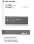
12. SPECIFICATIONS
FM tuner
I'
Frequency Range: 87.9 MHz to 107.9 MHz
Usable Sensitivity: 11 dB
50 dB Quieting Sensitivity: 17 dB
Alternate Channel Selectivity: 75 dB
E
1
188 mm
.1
~~
1
~I
_I
Stereo Separation (1 kHz): 35 dB
l-
Frequency Response (±3 dB): 30 Hz to 15 kHz
AM tuner
178 mm
-I
58mm
Notes:
• Specifications comply with JEITA Standards.
Frequency Range:
AM 530 kHz to 1710kHz
• Specifications and design are subject to change
without notice for further improvement.
Usable Sensitivity: 25 dB
• Please make sure when connecting external power
amplifier, that you properly, to the car chassis,
ground the amplifier.
CD player
• If this is not done, severe damage to the source
unit may happen.
System: Compact disc audio system
Usable Discs: Compact disc
Frequency Response: 10Hz to 20 kHz (±3 dB)
Dynamic Range: 87 dB (1 kHz)
Harmonic Distortion: 0.01 %
Audio
Maximum Power Output: 180 W (45 W X 4 ch)
Bass Control Action (100 Hz): ±14 dB
Treble Control Action (10 kHz): ±14 dB
Power Output:
Line Output (with AlC 1 kHz, 10 ohms): 1.8 V
21 W RMS x 4 Channels at 4 0 and
THD+N
General
Signal to Noise Ratio:
70 dBA (reference: 1 W into 40)
Power Supply Voltage:
14.4 V DC (10.8 V to 15.6 V allowable), negative ground
Current Consumption: Less than 15 A
Speaker Impedance: 4 ohms (4 ohms to 8 ohms allowable)
Weight: 2.42 lb. (1.1 kg)
Dimensions:
178 mm Width X 50 mm Height X 152 mm
Depth
24
~
1%
Clarion Co., Ltd.
All Rights Reserved. Copyright © 2006: Clarion Co .. Ltd.
Printed in Malaysia I '''.rr·''',,· ir"
Ilmpreso en Malasia
982-1133-20
982-1133-31
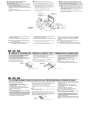
InstallationlWire Connection Guide
Guia de instalac;ao/conexao dos cabos
Guia de instalaci6n/conexi6n de cables
mlD rBD GIlD
BEFORE STARTING I ANTES DE COME<;AR I ANTES DE COMENZAR
-1.
This set is exclusively for use in cars with a
negative ground, 12 V power supply.
2. Read these instructions carefully.
e
3. Be sure to disconnect the battery"
terminal before starting. This is to prevent short circuits during installation (Figure 1).
1.-Este aparetho
e para usa exclusivo em veiculos com
negativQ aD lerra,alimenlaC;c30 de 12 V.
2.-Leia estas instruc;oes cuidadosamente.
1. Esta unidad ha sido diseiiada para utilizarse
exclusivamente en autom6viles con fuente de
alimentaci6n de 12 V, y negativo a tierra.
3.-Cetifique-se de desconectar 0 terminal" 0" da baleria
antes de iniciar, isto evitara curtos circuitos
durante a instalaC;<3o (Figura 1).
2. Lea cuidadosamente estas instruGciones.
3. Antes de comenzar, cerci6rese de desconectar el terminal
de la bateria. Esto es para
"8"
evitar cortocircuitos durante la instalaci6n
(Figura 1).
e
~
<±)
Car battery
Bateria de autam6vel
Baterfa del autam6vH
Figure 1 f Figura 1 I Figura 1
mlD mll!I GIlD
-2. CAUTIONS ON INSTALLATION I PRECAUCOES NA INSTALACAo I
1. Prepare all articles necessary far installing the source unit before
1.Prepare lodos as elementos necessarios para instala<;.3o da unidade
fonle antes de iniciar
21nstale 0 aparelho dentro de um angulo de 30° do plano horizontal
(flgura 2).
3.Se qualquer trabalho for necessario na carroceria do carro como
furos, consulte 0 revendedor do seu autom6vel.
4.-Use us parafusos fornecidos para instalac;ao. Outros parafusos podem causar danos. (Figura 3).
starting.
2. Install the unit within 30° of the horizontal plane (Figure 2).
3. If you have to do any work on the car body, such as drilling holes,
consult your car dealer beforehand.
4. Use the enclosed screws for installation. Using other screws can
cause damage (Figure 3).
Max.30~
Max. 30
Max. 300
Chassis I Chassis I Chasis
~@@
[
--l.-
~
1. Antes de comenzar, prepare todos los elementos necesarios para
instalar la unidad fuente.
2. Instale la unidad con un angulo de 30° sabre el plano horizontal
(Figura 2).
3. Si tiene que realizar cualquier trabajo en la carrocerfa, como taladrado de orificios, etc., consulte al proveedor de su autom6vil.
4. Utilice los tomillos suministrados para la instalaci6n. La utilizaci6n
de otres tomillos pod ria resultar en dalios (Figura 3).
Chassis I Chassis I Chasis
~
Damage
~g:~~
@
-b-,.,..,-"-,-,..-,,-mm-'",,.h.,...=5116.(6 mm l
----=::"'-.-
Figure 21 Figura 2 I Figura 2
mlD rBD
I PRECAUCIONES PARA LA INSTALACION
Figure 31 Figura 3 I Figura 3
GIlD
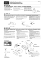
-3. INSTALLING THE SOURCE UNIT IINSTALANDO A UNIDADE
• Universal Mount
1. Place the universal mounting bracket into the instrument panel,
use a screwdriver to bend each stopper of the universal mounting
bracket inward, then secure the stopper as shown in Figure 4.
2. Wire as shown in Section 6.
3. Insert the source unit into the universal mounting bracket until it
locks.
4. Take care of the top and buttom of the outer escutcheon and
mount it so that all the hooks are locked.
Notes:
1) Some car models require special mounting kits for proper installation. Consult your Clarion dealer for details.
2) Fasten the front stopper securely to prevent the source unit from
coming loose.
FONTE IINSTALACION DE LA UNlOAD FUENTE
• Montagem Universal
1. Coloque 0 suporte de montagem universal no painel de instrumenlos,
• Montaje Universal
1. Coloque el soporte de montaje universal en el tablero de instruutilize uma chave de fenda para dobrar cada Irava do suporte de
mentos, utilice un destornillador para doblar cada reten del
montagem universal para dentro, depois assegure 0 travamento como
soporte de montaje universal hacia adentro, y despues asegure
el reten camo se muestra en la Figura 4.
mostra a Figura 4.
2. Conecte as cabos como mostrado na Se<;ao 6.
2. Conecte los cables como se muestra en la Secci6n 6.
3.lnsira a aparelho no suporte de montagem universal
3. Inserte la unidad fuente en el soporte de montaje universal hasta
ate que ele trave.
que quede enganchado.
4. Tenha cuidado com a parte superior e inferior da moldura
4. Tenga cuidado can la parte superior e inferior de la moldadura
externa de forma que todos as ganchos sejam lravados.
externa del escutcheon y montela de forma que lodos los
ganchos queden bloqueados
Notas:
1) Alguns modelos de autom6vel necessitam da kits de instalac; 030
especial para instalac;ao apropiada.
Consulte seu revendedor de Clarion para detalhes.
2) Aperte as travas firmemente para evitar que a unidade fonte
fique solta.
• Console opening dimensions
• Oirnensoes da abertura da console
• Dimensiones de la abertura de la consola
Hole
Abertura
Orificio
Ir
Stoppers
Travas
Retanas
Notas:
1) Algunos madelos de autom6vifes requieren juegos de montaje
especiales para realizar la instalaci6n apropiada. Solicite los
detalles a su proveedor Clarion.
2) Apriete con seguridad el reUm frontal para evitar que se afloje
la unidad fuente.
Instrument panel
Painel de instrumentos
Tablero de instrumentos
,/~
Hexagonal bolt
Parafuso hexagonal
Perno hexagonal
Slrap
Suporte
Soporte
* This part is not provided in some models
* Esta pep nac e fornecida em alguns modelos
* Esla pieza no se suministra en algunos modelos
TOp
Pane superior
Parte superior
t
¢~
Source Unit
Unidade fonte
~nidad fuente
Inslallation direction
Dire<;i'io da Instalacao
Direccion de instalaci6n
..
Bottom
Parte i'lfenor
Parte inferior
Outer escutcheon side view
Vista lateral de moldura externa
Vista lateral de la moldura externa
~~
Spring
~-----Mola
Resarte
Stoppers
Travas
Retenes
~ Moldura
Outer escutcheon
extema
Moldura externa
Note:
BefOl'e attaching the universal mounting brac!let. slightly bend
the spring toward the insH::le with your fingers and atlach it to lhe
side of car.
Nota:
Antes de Instalar 0 suporte de montagem universal,dobre levemenle
amolaparadenlrocomseusdedoseprenda-analaleraldo
veiculo
Nota:
Antes de tijarelsoportedemonlaje universal,doble
ligeramenteelresortehaciaelinteriorconlosdedosyfijeloen
la parte lateral delautomovil.
Figure 41 Figura 4 I Figura 4
• Fixed Mount (Using the bracket originally equipped in vehicle)
This unit is designed for fixed installation in the dashboard.
If the vehicle is equipped with a factory-installed radio, install the source unit with the
parts and screws marked (. ). (Figure 8)
If the vehicle is not equipped with a factory-installed radio. obtain an installation kit to
install the source unit in the following procedure.
1. Secure the mounting brackets to the chassis as shown in Figure When the
source unit is installed without the universal mounting bracket. hOles exist;
modification. such as drilling new holes, of the mounting brackets may be required
fOl other models.
a.
.Montagem Filea (utilizando 0 supone original do velculo)
Este aparelho fol projelado para montagem ha no painel de inslrumenlos
Sa 0 veieulo eQulpado de fabrica eem um radiO. instale ullidade fonle eom
As pe c;as e parafuses marcados eom (.) (Figure 8)
Se 0 veiculo nao for equipado de fabrlca cen um radiO. adquira um kit de
lnstalacao para instalar a unldade fonle com os segulntes procedimentos:
1. Prenaa os supones de monlagem 00 chassi como mostra a Figura 8
Quando a unidades fonte instalada sem 0 supone de mentagem universal.
turas e:o:istentes. modiflCa¢>es. cemo novos turas nos suportes de
Montagem podem ser necessanos para oufros modelos
e
e
instal~o (S~o 6)
2. Wire as shown in Installation (Section 6).
2. Fat;<! a fiacao como mostrado em
3. Secure the unil in the dashboard, aod then reassemble the dashboard aod the
3_ Prenda a unidade no palnel e depots. volte a montar 0 palnel de
cenler panel.
• Monlura fila (Usando el soporte orlglnalmente equipado en el vehlculo)
Esta unidad ha sido disenado para ta Instalaei6n fija en el tablero de instrumentos.
5i et yehlculo esta equipado con una radio instalada en fabrica. instale la unidad de la
fuente con las piezas los lornmas marcados con ( .). (Figura 8)
5i el vehiculo no esta equipado con una radio inslalada en fabrica, obtenga un juego de
Instalaci6n para Instalar la unidad de la fuente mediante el procedimiento que se da a
Conlinuaci6n:
1. Asegure los soportes de mootaje al chasis como se mueslra en la Figura 8.
Cuando la unidad de la tuente esta instalada sin el soporte de montaje universal,
e:o:isleodo agujeros, puede requerirse una mOOiflCaCi6n para olros modelos, tal
como perforaeiOn de nuevos agujeras.
a
2. Realice el cableado tal como se muestra en instalaci6n (5ecci6n 6).
3. Asegure Ia unidad en eltablero de instrumentos. y luego vuelva armar ellablero
lnstrumentos e 0 painel central.
...........-.
de instrumentos y el panel central.
"""'ro
r
(l __ IDf""''-"_riltll_1
~
Pa
~
ll_pa'"~""Y<lclII""'L~{llll"""'\
0. InSlr......nlOS
lnslrUtMrrtOS
Sop:Irle ..........
(1~j*a"'_~~_J
Flg....... /Flg"ra.,Flgun.
It:
The parts and screws wilh this mark are used 10 install radio or
included in the installation kit.
*: As pe9as e parafusos com esta marca sao usados para lnstalar a
Las piezas y tornillos can esla marea se utHizan para instalar la
radio 0 se suministran con el juego de instalaci6n.
*: Os parafusos com esla marca sao utilizados original mente no veiculo. *: Los tornillos con esta marea estan originalmente fijados a los
Nota 1: In some cases, the center pane' may require some modification (trimming, filling, etc.).
Nota 1: Em alguns casas, a painel central pode necessitar de a/guma
modifica y8o (recone. preenchimento.etc.)
Nota 2: If a hook on the installation bracket interferes with the unit,
bend and flatten it with a nipper or a similar tool.
Nola 2: Se urn gancho no supone de ins/a/ayao in/errerir no apare/ho
dobre-o com urn aticate au ferramenta similar.
aulom6viles.
"mID"
-4. REMOVAL OF THE SOURCE UNIT I REMOCAo DA UNIDADE FONTE
1. When removing the source unit, disassemble it in the reverse of
the order in Section -3. INSTALLING THE SOURCE UNlr.
2. Remove the detachable control panel (DCP).
• For instructionson removing the DCP,refer to the owner's manual
3. Press the outer escutcheon upward and remove it (Figure 9).
4. Insert and lock the hook plates (Figure 10).
,
It:
radio ou incluidas no kit de instalar;ao.
*: The screws with this mark are originally attached to the vehicle.
Nota 1: En algunos easos, ef panel central puede requerir eiertas
rnodificaciones (recone, limado. etc.).
Nota 2: Si a/gun gancho de/ soporte de montaje interfiere con la unidad,
d6blelo y presionelo can una pinza de corte u otra herramienta similar.
I DESMONTAJE DE LA UNIDAD FUENTE
1. Quando remover a unidade fonte. desmonte·a na ordem inversa da
5e,,0 "3. IN5TALANDO A 'UNIDADE FONTE"
2. Remova 0 painel de Controle Destac:avel (DCP).
• Para instrucoes sabre a remcw;ao do DCP. consulte 0 manual de
instrucoes.
3. Pressione a moldura extema para elma e remova-a (Figura 9).
4. Insira as chaves de encalxe (Figura 10).
M~ _ _ ._~;';~
_._",~~._• •~.- ""1oJ<'''''''/'
1. Para desmontar la unidad fuente, realice el procedimienlo inverso al de la Secci6n -3. INSTALACICN DE LA UNlOAD FUENTE-.
2. Desmonte el panel de control desmontable (DCP),
• para instrucciones sobre como desmontar el DCP, consulte el
manual de instrucciones.
3. Presiooe la moldura exterior hacia afuera y extraigala
(F;gure 9).
4. Inserte y bloquee las placas de enganche (Figura 9).
5. Tire de las placas de enganche para extraer la unidad fuente.
F\ton.IF"_.,I.,.......
. . GIlllI!m!I . .
CAUTIONS ON WIRING I CUIDADOS NA CONEXAO DOS CASOS I PRECAUCIONES PARA LA CONEXION DE CABLES
-5.
1. Be sure to tum the power off when wiring.
2. Be particularly careful where you route the wires.
Keep them well away from the engine, exhaust pipe, elc. Heat
may damage the wires,
3. If the fuse should blow, check that the wiring is correct.
If it is, replace the fuse with a new one with the same amperage
rating as the original one.(Figure 11)
Note:
... There are various types of fuse holder. 00 not let the battery
Side touch other metal parts.
4, When the main power supply fuse in the car is 15Aor Iess,purchase an
autOlTlOvile cable that can withstand 15Aand supply this unit with power
direclly from the battery 10 ensure that the unit will operale normally.
Note thai a fuse must be installed at a distance no longer than 30cm
from the cable battery terminal to prevent accidents.
1. Certifique-se de desJigar a aJimentayao da unidade antes de fazer conex6es
2. Seja especialmente cuidadoso quando direcionar as fios. Manlenha-os longe
do motor. escapamento ,etc. 0 calor pode danificar as fios.
3. Se urn fusivel queimar, verifique se a fia~o esta correia.
Se estive .troque 0 fusivel por urn novo de mesma amperagem do anginal
(Figura 11)
Nota:
• Existem VilrloS tipos de suportes de fusivel. Nao deixe que 0 lado da batena
toque em oolras partes melalicas.
4. Quando 0 fusivel da atimentayao principal do veieulo for de 15 Aou menor
adquira urn cabo automotivo que possa resislir a 15 Ae alimente a unidade
diretamente da baleria para assegurar que a aparelho opere normalmente.
Note que um fusivel deve ser instalado a uma distancia menor que 30 em do
terminal do cabo da bateria para evitar acidentes.
,~~
1. Antes de hacer las conexiones, asegurese de desconectar la alimentaci6n de la unidad.
2. Sea especialmenle cuidadoso al dirigir y fijar los cables.
mantE!ngalos alejados del motOf, tuba de escape, etc. EI calor
puede daiiar los cables.
3. Si el fusible se quema, revise las conexiones.
Si esta quemado, reemplace el fusible por otro nuevo con el
mismo valor de amperaje que el original.(Figura 11)
Nota:
It
Existen varios tipos de portafusibles. No permita que el terminal
def fado de la bateria toque otras partes metaficas.
4. Cuando el fusible de alimentacion principal del aut0m6vil sea de 15A 0
menos,adquiera un cable para aut0m6v~ que pueda resistir 15A y
alimente esta unidad directamente desde la bateria para serciorarse de
que pueda funcionar normalmenle.
Tenga en cuenta que para evitar accidenles,debera instalar un fusible en
el cable que va a las lerminales de la baleria a una distancia no superior
a los 3Ocm.
ea..... d;oF"s.i><e1
~deF
,.....Ulfig... U , '..... ',
. . l2D IIID
-6.
WIRE CONNECTIONS I CONEXAO DOS CABOS ICONEXION DE CABLES
ToeKternlllamplifier
... To eliminate audio short circuits. do not remove the caps of unused RCAcabtes
CAUTION: Please make sure when connecting 8Klernal power amplifier, that you properly, to the car
chassis, ground the amplifier. If this is not done, severe damage to the source unit may
happen.
Para amplificador (!xterno
Connecl to remote tum-on lead of amplifier.
* Para eliminar os curtos circUitos de audiO, nao remMa as capas dos cabos RCA nao ulilirados.
CUlDADO: Quando conect'lr urn i1mplificador de potencia exlerno certifique·se de aterrar
adequadamente aD chassi do aulom6vel caso contraria serios danes podem Dcorrer
naunidadefonte.
Aunamplificadorexterno
... Para eliminar los cortocircuitos de audio, no quite los casquillos protectores de los cables RCA no utiliza-
,,,
{2
-
Conduciorazul/bianco. conductor de
laalimentaci6ndelampliflcador.
I~
'L..JJ--=
PRECAUCION: Cuando conecte un ampllficador de potencia externo, cerclcrese de ponerlo
adecuadamente a tierra en el chasls de su autom6vil.SI no 10 hlclese,la unldad
fuentepodriadanarseseriamente,
cone~i6nde
Connect illo lhe car power supply terminal for Ihe antenna
Conecleaoterm'naldeallmentaoyaodaantena
Conecteloallerminaldealimentaci6ndelaantena
Antenna
Anlena
Antena
Radio pin oul
?,nouLdQrildlO
Pin out del radio
~
~
>
1
~
1
~
>
<I
J
<I
rJ
>
(
U
<I
C
>
lNDlE5 TcM
NAMc
REAR RiGHT -..
B2 REAR RIGHT B? FRDNT RIGHT -IB' FRDNT RiGHT
Be FPDNT LEFT -IB6 FPDNT LEFT ,B7 REAR LEFT
B8 Rt.-AR LEFT
NO SYSTEM NAME
RFM
'2 A![J! USF/J
A31 NO! US£/J
IE:
CONNECTOR
"'5
,A6
"
;1 -I ~I
~ <! ,I ~I ~I '",
'1 '! 'I ,~
A1("~M)y I
:~u::..--=~~....
AUTO ANT
ILLUMINATIDN
B/UP f B
GRDUND
""'0''''''"''
::");::':::,::;u••
II
0
I]
lJ
,
,>
~
~
u
,1
~'i~
<r i~
u::::
'
U
I
+Gray/~C1nlal
C
coco
~
~"!
T_'ft.'••
E3
lJ
@
, ,
~
-;-!Jo! ~I "lOr
Ace
....
DESCRIPTION
18 A~~ FUSE
rUSIBLF /JF
104MP
.,
<I A7
U '8
~
f
16·Pin connector Extension Lead
(Altached 10 the source unit)
Cabo de edensao com conector de 16 pinos
(InSlaladonaunidadefonle)
Cable prolongiildor de 16 contactos
(Fijadoalaunidadluenle)
+Gris
Front Right
Fronlaldireilo
Delanteroderecho
PRECAUCION:
- Grayl8lack /. Cmla/Prelo 1- GrislNegro
+While/+ Branco/+ Blanco
Front Left
Frontalesquerdo
Delanleroizquiedo
Antes del uso de este
conector, verlflque la
conflguraclon de cables
WARNING:
Before using this
connector, check wire.
configuration.
White/Black 1- Branco/Preto /- Blanco/Negro
+Purple / + Purpura
Note:
Some units do not have connecting leads or jacks
(Refer to oJ.
Nota:
Algumas unidades nao possuem cabos de conexao
(Referencia 0)
Nota:
Algunas unidades no tienen cables de conexi6n ni conectores.
(Retierase a *)
1 P(,rpuro
Rear Righi
Traseirodireito
Traseroderecho
- Purple 1- Black / Purpura- Preto! !I.·lorado/Negro
+ Green/+Verde /+verde
Rear Left
TrasieroEsquerdo
Trasublzqulerdo
- Green/Black I - Verde/PelTo /- Verde/Negro
Yellow wire (Bus power lead)Fio amarelo (fic de alimental;ao do bus)'
Conductor amarillo (conductor de alimentacl6n de bUS)'
Connecldireetlyto baltery
Conectediretamenteabateria
Conectelodirectamenlealabateria
4· Speaker system
•
Sislema de 4 alto·falantes
Sistemas de 4 altavoces
No.
I
DESCRIPTION
1
FRONT RIGHT Gra
Red
2
FRONT LEFT Gra
White
Red wire (Power lead)
Fiovermeiho(fiodealll'l1enta~ao)
Conductor rojo (ConductOf de alimenlaci6n)
Accessory+12
Fuse (1 A)
Ace~s6no .j.12V Fus;vel{l A)
Acoosorio+12
Fusible (1 A)
Black wire (Ground lead)
Fiopreto(lioterra)
Conductor negro (CondUclorde puesta a tierra}
No.
DESCRICAo
FRONTAL DIRE ITO. CINZA (VERMElHOj
FRONTAL ESOUERDO, CINZA (BRANCO)
1
Conneclto vehicle chassis ground
Conecte a uma parte metallca do chassi do veiculo
Conecleloauna partemetalicadeichasisdeiliehiculo
2
Orange wire (1Iluminalion lead)
FiolaranJa(fiodeilumll1a~30}
Conductoranaranjado (conductor de iluminaci6n)
Connecl il to the car power supply terminal for illumination
Conecte ao terminal de alimenla v30 do aulomovel para ilum,nar;:ao
Conectelo al terminal de alimentacion del aulom6l1i1 para iluminacion
No.
1
2
DESCRIPCION
I
DELANTERO DERECHO Gris (Rojo)
DElANTERO IZQUIERDA Gris Blanco
mm~GIE
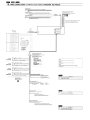
-7. SYSTEMS EXAMPLE I EXEMPLO DE SISTEMA I EJEMPLOS DE SISTEMAS
• Example of the system using an external amplifier (Audio Visual)
• Exemplo de sistema utilizando urn amplificador externo (audio visual)
• Ejemplo de sistema utilizando un amplificador externo (audiovisual)
:[)r-ill:d""""T!::::l=
l_____ ~Jc<::="
'"
~
~
-,
2-·
1
J
E3
@
3
Source unit
RCA extension cable sold separatelY)
I Center speakers (with amplifier)
4
I REM & ANT cable
1
2
[]
[]
0
0
[]
0
1:1
[]
Unidad fuente
Cable de extension RCA
Altavoz central (con ampliflcador)
Cable de REM & ANTENA
BIB II:!III . . .
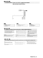
-S. GENERAL CAUTIONS IPRECAUCOES GERAIS I PRECAUCIONES GENERALES
1. Do not open the case. There are no user serviceable parts inside.
If you drop anything into the unit during installation, consult your
dealer or an authorized CLARION service center.
2. Use a soft, dry doth to clean the case. Never use hard cloth, Ihin-
~~ie~~g~e~o~l~fo~~la~~~~~ ~ff~ed~7rt ~~fr:.little
cold or warm
1. No abra la caja. En el interior no hay piezas que pueda reparar el
1. Nao abra 0 gabinete Nao existem partes que possam ser reparadas
usuario. Si dentro de la unidad entra algo durante la instalaci6n,
pelo usuario em seu interior. Se alga caif no interior do aparelho
durante a instalacao, consulte seu revendedor au urn servi<;o autorizado
~T1:~l~~. su proveedor 0 a un centro de servicio autorizado por
CLARION,
2. Use um pano macio e seco para limpar a gabinete. Nunca use panos
2. Para limpiar la caja, utilice un pano suave y seco. no use nunca
un pano duro, diluidor de pintura, benceno, alcohol, etc. Para fa
grosseiros, tiner, benzina, alcooLetc. Para manchas de sujeira. aplique
suciedad resistente, aplique un poco de agua fria 0 caliente a un
urn poueo de agua fria ou morna com um pano maeio e depois seque
pano suave y frote suavemente la parte sucia.
IMPORTANTE'
A instalacao impr6pria pode causar danos no aparelho au
autom6vel. Se nao liver experiencia suficienle. consulte um
instalador qualificado. 0 corte dos fios de terra anulara a
garantia
IMPORTANT:
Improper installation may cause damage to your unit or car. If you
do not have the appropriate experience, consult a qualified
installer. Cutting chassis wire leads voids the warranty.
IMPORTANTE:
La instalaci6n inapropiada puede causar danos en su unidad 0 su
autom6vil. Si usted no posee la experiencia apropiada, consulte a
un instalador calificado. EI corte de los conductores de puesta a
tierra (carroceria) anulara la garantia.
BIB II:!III . . .
-9.
DETACHABLE DCP CAUTION I PRECAUc;OES PARA DESTACAvEL DCP I PRECAUSIONES PARA DESMONTAR DCP
Note:
The following procedure should be follow to remove
control panel DCP (detachable DCP) to avoid damage
to unit.
1. To remove DCP (detachable DCP) the left side should be
lift slightly to avoid stueking
Nota:
o seguinle procedimiento deve ser seguido ao retirar 0 painel frontal do
Nota:
El siguiente procedimiento debe de ser seguido al retirar et DCP
(caralula desmonlable) para evilar danos a la unidad.
radio (frontal desmonlavel) para evitar danos a unidade.
1 Ao retirar 0 painel frontal do radio (frontal removivel) deve se levanlar
Iigelramente a parte inferior esquerda para removela.
1. AI quitar el DCP (caratula del radio desmontable) la parte inferior
Izquierda se debe levantar ligeramente para evitar atoramiento.
Clarion Co., Ltd.