1
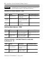
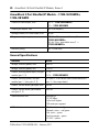
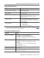
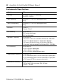
Installation Instructions
ArmorBlock 16-Point EtherNet/IP Module,
Series A
Catalog Numbers 1732E-IB16M12, 1732E-OB16M12,
1732E-16CFGM12, 1732E-16CFGM12W, 1732E-IB16M12W
Topic
Page
Important User Information
2
Environment and Enclosure
3
Prevent Electrostatic Discharge
3
About the EtherNet/IP ArmorBlock 16-Point I/O Modules
4
Catalog Number Explanation
6
Install the Module
6
Set the Network Address
6
Mount the Module
7
Product Dimensions
8
Connect the I/O, Network and Auxiliary Cables to the ArmorBlock Module
9
Specifications
19
2 ArmorBlock 16-Point EtherNet/IP Module, Series A
Important User Information
Solid state equipment has operational characteristics differing from those of electromechanical
equipment. Safety Guidelines for the Application, Installation and Maintenance of Solid State Controls
(publication SGI-1.1 available from your local Rockwell Automation sales office or online at
http://literature.rockwellautomation.com) describes some important differences between solid state
equipment and hard-wired electromechanical devices. Because of this difference, and also because of
the wide variety of uses for solid state equipment, all persons responsible for applying this equipment
must satisfy themselves that each intended application of this equipment is acceptable.
In no event will Rockwell Automation, Inc. be responsible or liable for indirect or consequential damages
resulting from the use or application of this equipment.
The examples and diagrams in this manual are included solely for illustrative purposes. Because of the
many variables and requirements associated with any particular installation, Rockwell Automation, Inc.
cannot assume responsibility or liability for actual use based on the examples and diagrams.
No patent liability is assumed by Rockwell Automation, Inc. with respect to use of information, circuits,
equipment, or software described in this manual.
Reproduction of the contents of this manual, in whole or in part, without written permission of Rockwell
Automation, Inc., is prohibited.
Throughout this manual, when necessary, we use notes to make you aware of safety considerations.
WARNING
IMPORTANT
ATTENTION
Identifies information about practices or circumstances that can cause an
explosion in a hazardous environment, which may lead to personal injury or death,
property damage, or economic loss.
Identifies information that is critical for successful application and understanding
of the product.
Identifies information about practices or circumstances that can lead to personal
injury or death, property damage, or economic loss. Attentions help you to identify
a hazard, avoid a hazard, and recognize the consequences.
SHOCK HAZARD
Labels may be on or inside the equipment, for example, a drive or motor, to alert
people that dangerous voltage may be present.
BURN HAZARD
Labels may be on or inside the equipment, for example, a drive or motor, to alert
people that surfaces may reach dangerous temperatures.
Publication 1732E-IN002B-EN-E - February 2011
ArmorBlock 16-Point EtherNet/IP Module, Series A 3
Environment and Enclosure
Follow these guidelines for environment and enclosure information for this
equipment.
ATTENTION
This equipment is intended for use in overvoltage Category II applications (as
defined in IEC 60664-1), at altitudes up to 2000 m (6562 ft) without derating.
This equipment is considered Group 1, Class A industrial equipment according
to IEC/CISPR 11. Without appropriate precautions, there may be difficulties
with electromagnetic compatibility in residential and other environments due
to conducted and radiated disturbances.
This equipment is supplied as enclosed equipment. It should not require
additional system enclosure when used in locations consistent with the
enclosure type ratings stated in the Specifications section of this publication.
Subsequent sections of this publication may contain additional information
regarding specific enclosure type ratings, beyond what this product provides,
that are required to comply with certain product safety certifications.
In addition to this publication, see:
• Industrial Automation Wiring and Grounding Guidelines, Rockwell
Automation publication, 1770-4.1, for additional installation
requirements.
• NEMA Standard 250 and IEC 60529, as applicable, for explanations of
the degrees of protection provided by different types of enclosure.
Prevent Electrostatic Discharge
Follow these guidelines when you handle this equipment.
ATTENTION
This equipment is sensitive to electrostatic discharge that can cause internal
damage and affect normal operation. Follow these guidelines when you
handle this equipment.
• Touch a grounded object to discharge potential static.
• Wear an approved grounding wrist strap.
• Do not touch connectors or pins on component boards.
• Do not touch circuit components inside the equipment.
• Use a static-safe workstation if available.
• Store the equipment in appropriate static-safe packaging when not in
use.
Publication 1732E-IN002B-EN-E - February 2011
4 ArmorBlock 16-Point EtherNet/IP Module, Series A
About the EtherNet/IP ArmorBlock 16-Point I/O
Modules
The EtherNet/IP 1732E ArmorBlock is a 24V DC I/O module that
communicates via EtherNet/IP. The sealed IP65, IP67 and IP69K housing of
these modules requires no enclosure. Note that environmental requirements
other than IP65, IP67 and IP69K may require an additional appropriate
enclosure. I/O connectors are sealed M12 style.
EtherNet/IP network uses advanced network technolgy, for example,
producer/consumer communication, to increase network functionality and
throughput. Visit our web site at www.ab.com/networks for
producer/consumer technology information and updates.
Publication 1732E-IN002B-EN-E - February 2011
ArmorBlock 16-Point EtherNet/IP Module, Series A 5
EtherNet/IP ArmorBlock 16-Point I/O Module
Functional
Earth(1)
EtherNet/IP
D-Code M12
Connector
Status
LEDs
Plastic
Housing
I/O
Connectors
I/O
Connectors
Node
Address
Switches
Protective
Earth
MOD
NET
LINK
0
15
1
14
2
13
3
12
4
11
5
6
10
9
Metal
Housing
I/O
Connectors
8
7
Auxiliary
Power
EtherNet/IP
D-Code M12
Connector
EtherNet/IP
X10
P
W
R
X100
X1
(2)
44231
44232
Node
Address
Switches
Protective
Earth(2)
(1)
Functional Earth grounds the I/O block’s EtherNet/IP communication circuitry which is designed to
mitigate the effect of noise on the network. See 10 for network connections.
(2)
Protective Earth is provided for the grounding of field devices and is internally connected to each Pin 5 of
the M12 I/O connectors. See 11 for I/O connections.
Publication 1732E-IN002B-EN-E - February 2011
6 ArmorBlock 16-Point EtherNet/IP Module, Series A
Catalog Number Explanation
Refer to the table for a description of the catalog numbers.
Cat. No.
Description
1732E-IB16M12
EtherNet 24V DC 16 Input
1732E-OB16M12
EtherNet 24V DC 16, 2 A Output
1732E-16CFGM12
EtherNet 24V DC 16 Selectable
Points
1732E-IB16M12W
EtherNet 24V DC 16 Input
WeldBlock Metal Housing
1732E-16CFGM12W
EtherNet 24V DC 16 Selectable
Points
WeldBlock Metal Housing
Network
Connector
Auxiliary
Power
Single D-Code M12
Single 4-pin
mini
Single D-Code M12
Single 4-pin
mini
Install the Module
Refer to the following sections to install your module.
• Set the Network Address
• Mount the Module
• Connect the I/O, Network and Auxiliary Cables to the ArmorBlock
Module
Set the Network Address
The I/O block ships with the rotary switches set to 999 and DHCP-enabled.
To change the network address, you can do one of the following:
• adjust the switches on the front of the module.
• use a Dynamic Host Configuration Protocol (DHCP) server, such as
Rockwell Automation BootP/DHCP.
• retrieve the IP address from nonvolatile memory.
The I/O block reads the switches first to determine if the switches are set to a
valid number. Set the network address by adjusting the 3 switches on the front
Publication 1732E-IN002B-EN-E - February 2011
ArmorBlock 16-Point EtherNet/IP Module, Series A 7
of the module. Use a small blade screwdriver to rotate the switches. Line up
the small notch on the switch with the number setting you wish to use. Valid
settings range from 001...254.
Network Address Example
This example shows
the network address
set at 163.
44233
When the switches are set to a valid number, the I/O block’s IP address is
192.168.1.xxx (where xxx represents the number set on the switches). The
I/O block’s subnet mask is 255.255.255.0 and the gateway address is set to
0.0.0.0. When the I/O block uses the network address set on the switches, the
I/O block does not have a host name assigned to it or use any Domain Name
Server.
If the switches are set to an invalid number–for example, 000 or a value
greater than 254 excluding 888–the I/O block checks to see if DHCP is
enabled. If DHCP is enabled, the I/O block asks for an address from a
DHCP server. The DHCP server also assigns other Transport Control
Protocol (TCP) parameters.
If DHCP is not enabled, the I/O block uses the IP address, along with other
TCP configurable parameters, stored in nonvolatile memory.
Mount the Module
Mount the module directly to a machine using two mounting holes, 5.3 mm
(0.208 in.) in diameter. Mounting holes accommodate #6 (M3) pan head
screws. The torque specification is 6.912 cm-kg (6 in-lbs).
Publication 1732E-IN002B-EN-E - February 2011
8 ArmorBlock 16-Point EtherNet/IP Module, Series A
Product Dimensions
Refer to the mounting dimensions illustration to help you mount the
modules.
65 mm
(2.56 in.)
43.25 mm
(1.70 in.)
26.5 mm
(1.04 in.)
0
15
1
14
2
13
3
4
12
11
5
6
10
9
179 mm (7.05 in.)
169 mm (6.64 in.)
8
7
P
W
R
44234
Front View
Side View
Mount the Module in High Vibration Areas
If you mount the module in an area that is subject to shock or vibration, we
recommend you use a flat and a lock washer to mount the module. Mount the
flat and the lock washer as shown in the mounting illustration. Torque the
mounting screws to 6.912 cm-kg (6 in-lbs).
Publication 1732E-IN002B-EN-E - February 2011
ArmorBlock 16-Point EtherNet/IP Module, Series A 9
High Vibration Area Mounting
Lock Washer
Flat Washer
44235
Connect the I/O, Network and Auxiliary Cables to the
ArmorBlock Module
The ArmorBlock EtherNet/IP family has 5-pin micro-style connectors.
We provide caps to cover the unused connectors on your module. Connect
the quick-disconnect cord sets you selected for your module to the
appropriate ports.
Publication 1732E-IN002B-EN-E - February 2011
10 ArmorBlock 16-Point EtherNet/IP Module, Series A
Network Connectors
Refer to the pinout diagrams for the network connectors.
D-Code M12 Female Network Connector
(View into Connector)
Pin 1
M12_Tx+
Pin 2
M12_Rx+
Pin 3
M12_TxPin 4
M12_RxPin 5
Connector Shell Shield GND
4
1
3
2
5
44236
IMPORTANT
Use the 1585D–M4DC–H: Polyamide small body unshielded or the
1585D–M4DC–SH: Zinc die-cast large body shielded mating
connectors for the D-Code M12 female network connector.
When using shielded (STP) cable with metal housing WeldBlock
products 1732E-IB16M12W and 1732E-16CFGM12W, isolate the
shield at the ArmorBlock end of the cable. This minimizes the
effect of ground offsets.
IMPORTANT
Use two twisted pair CAT5E UTP or STP cable.
D-Code M12
Pin
1
2
3
4
Wire Color
White-Orange
White-Green
Orange
Green
Publication 1732E-IN002B-EN-E - February 2011
Signal 8-way Modular
RJ45 Pin
TX+
1
RX+
3
TX2
RX6
ArmorBlock 16-Point EtherNet/IP Module, Series A 11
I/O Connectors
Refer to the pinout diagrams for the I/O connectors.
Micro-style 5-Pin Female Input Connector
41452
(View into Connector)
Pin 1
Sensor Source Voltage
Pin 2
Input B
Pin 3
Return
Pin 4
Input A
Pin 5
PE
Self-configuring Connector
41452
(View into Connector)
Pin 1
Sensor Source Voltage
Pin 2
Input or Output B
Pin 3
Return
Pin 4
Input or Output A
Pin 5
PE
Micro-style 5-Pin Female Output Connector
(View into Connector)
Pin 1
Not Used
Pin 2
Output B
Pin 3
Return
Pin 4
Output A
Pin 5
PE
41452
The 1732E-16CFGM12 and the 1732E-16FGM12W self-configuring
modules contain both input and output functionality.
• If an I/O point is to be an output, dedicate that point as an output
with a wired load and energize it through a control program.
• Energized outputs show an associated active input that can be used as
a feedback mechanism to make certain that the output is on.
Publication 1732E-IN002B-EN-E - February 2011
12 ArmorBlock 16-Point EtherNet/IP Module, Series A
• If an I/O point is to be an input, wire the input device as normal and
leave the associated output de-energized at all times.
I/O Self-configure Circuitry
Turn output on
Output
circuit
From PLC
To PLC
Sensor or
actuator
Output scan list
Input scan list
Input is on
(or output is on)
Input
circuit
Connector pin
43601
Refer to the illustration for configuration operations.
Configure Operations
EtherNet/IP D-Code
M12 connector
M12 I/O
connectors
M12 I/O
connectors
Auxiliary power
Network address
switches
44231
Publication 1732E-IN002B-EN-E - February 2011
ArmorBlock 16-Point EtherNet/IP Module, Series A 13
The module is 24V DC Sink In/Source Out:
• 16 Input
• 16 Output
• 16 Input Or Output points or any mix of 16 (for example, 15 + 1; 8 +8)
The output is short circuit protected and output monitoring in
“Self-configuring” style.
Refer to On-Machine Connectivity Catalog, publication M117-CA001, for
Rockwell Automation cable and cord set offerings or access the Connection
Systems website at http://www.ab.com/connectionsystems/. You can also
use the configuration tools available at
http://www.rockwellautomation.com/en/e-tools/.
ATTENTION
Make sure all connectors and caps are securely tightened to properly seal the
connections against leaks and maintain IP67 requirements.
Auxiliary Power Cable
Attach the mini-style 4-pin connector to the mini-style 4-pin receptacle as
shown below.
Publication 1732E-IN002B-EN-E - February 2011
14 ArmorBlock 16-Point EtherNet/IP Module, Series A
Mini-style 4-Pin Female Connector (from power cable)
2
4
1
3
(View into Connector)
Pin 1
Output Power+
Pin 2
Sensor/MDL Power+
Pin 3
Sensor/MDL PowerPin 4
Output Power44237
Mini-style 4-Pin Male Receptacle (on the ArmorBlock)
4
2
3
1
(View into Receptacle)
Pin 1
Output Power+
Pin 2
Sensor/MDL Power+
Pin 3
Sensor/MDL PowerPin 4
Output Power44238
Auxiliary power is based on a 4-pin connector system and is used to provide
24V DC power to I/O modules and other devices. Running separate power to
these devices is most typically used for I/O devices with output connections
to prevent power supply interruption due to switching of outputs. However,
some devices require separate auxiliary power to power them regardless of the
presence of outputs.
Depending on the devices used, it may be possible to provide power through
only one pair of the four available pins, and in this case the other available pair
may be used for single channel E-stop through the use of special E-stop drop
or power T-ports and shorting plugs. Allen-Bradley E-stop T-ports and
shorting plugs are red in color for easy identification.
Publication 1732E-IN002B-EN-E - February 2011
ArmorBlock 16-Point EtherNet/IP Module, Series A 15
Interpret the LED Indicators
This module has the following indicators:
• Network, Module, and Link status indicators for EtherNet/IP
• Auxiliary Power indicator
• Individual I/O status indicators for inputs and outputs.
Armor WeldBlock
Module status indicator
Link status indicator
EtherNet/IP
Network status indicator
I/O status indicators
MOD
NET
LINK
0
15
1
14
2
13
3
12
4
11
5
6
10
9
I/O status indicators
8
7
X10
P
W
R
X100
Auxiliary power
status indicator
X1
44232
Publication 1732E-IN002B-EN-E - February 2011
16 ArmorBlock 16-Point EtherNet/IP Module, Series A
ArmorBlock
Link status indicator
Module status indicator
Network status indicator
I/O status indicators
I/O status indicators
Auxiliary power
status indicator
44231
Network Status Indicator – NET
State
Status
Description
Recommended Action
Off
Not online
The device is not
initialized or the module
does not have an IP
address.
Wait until the module has
completed initialization
or assign an IP address.
Flashing
green
No CIP connections
The device has no CIP
connections.
The device has an IP
address, but no CIP
connections are
established.
Establish a network
connection.
Green
CIP connections
The device is online, has
an IP address, and CIP
connections are
established.
None
Publication 1732E-IN002B-EN-E - February 2011
ArmorBlock 16-Point EtherNet/IP Module, Series A 17
State
Status
Description
Recommended Action
Flashing
red
Connection time out
One or more connections
have timed out.
Reset connections to the
module.
Red
Duplicate IP
The module has detected
that its IP address is
already in use.
Resolve the IP address
conflict.
Flashing
red/green
Self-test in
progress
The module is performing
a powerup self-test.
None
Module Status Indicator – MOD
State
Status
Description
Recommended Action
Off
Not powered
There is no power applied to
the device.
Apply power to the device.
Flashing
red/green
LED powerup
test
The module is performing a
powerup self-test.
None
Green
Module
operational
The module is operating
normally.
None
Flashing
red
Minor fault
The module has one of the
following recoverable
faults:
•Check your configuration
and cycle power.
•If a firmware update is in
progress, wait for it to
complete.
•Verify that IP address
switches are set to the
desired value.
•Firmware (NVS) update.
•IP Address switches have
changed.
Solid red
Critical fault
The module has one of the
following unrecoverable
faults:
•Self-test failure (checksum
failure or ramtest failure at
powerup).
•Firmware fatal error.
Cycle power to the module.
If that does not fix the fault,
contact your Rockwell
Automation representative.
The module may need to be
replaced.
Publication 1732E-IN002B-EN-E - February 2011
18 ArmorBlock 16-Point EtherNet/IP Module, Series A
IMPORTANT
The Module Status LED indicator remains solid red for a maximum of 30 s
while the module completes its POST (Power-On Self Test).
Network Link Status Indicator – LINK
State
Status
Description
Recommended Action
Off
No network link
There is no network link
established.
Establish a network link.
Flashing
green/off
Network link active
There is transmitting or
receiving activity to the
module.
None
Steady
green
Network link present
There is a network link to
the module.
None
Auxiliary Status Indicator – PWR
State
Status
Description
Recommended Action
Off
No auxiliary power
There is no auxiliary power
applied to the module.
Apply auxiliary power to the
module.
Green
Auxiliary power
present
There is auxiliary power
applied to the module.
None
I/O Status Indicator – Individual Channels as Indicated
by Numbers 0…15
State
Status
Description
Recommended Action
Off
Output not energized
or no valid input
Output is not
energized or input is
not valid.
None
Yellow
Output energized or
valid input
Output is energized
or input is valid.
None
Publication 1732E-IN002B-EN-E - February 2011
ArmorBlock 16-Point EtherNet/IP Module, Series A 19
Specifications
ArmorBlock 2-Port EtherNet/IP Module – 1732E-IB16M12x,
1732E-16CFGM12x
Attributes
Value
Number of inputs
16
Input type
Sink, 24V DC
Voltage, off-state input, max
5V DC
Voltage, on-state input, max
30V DC
Voltage, on-state input, nom
24V DC
Voltage, on-state input, min
11V DC
Voltage, sensor source, max
30V
Voltage, sensor source, min
11V
Current, off-state input, max
1.5 mA @ 5V DC
Current, on-state input, max
5 mA @ 30V DC
Input delay time - ON to OFF and OFF to ON
0…16000 μs
ArmorBlock 2-Port EtherNet/IP Module – 1732E-16CFGM12x,
1732E-OB16M12
Attribute
Value
Number of outputs
16
Output type
Source, 24V DC
Voltage drop, on-state output, max
0.5V DC
Voltage off-peak blocking, min
30V DC
Voltage, on-state output, max
30V DC
Voltage, on-state output, min
11V DC
Voltage, on-state output, nom
24V DC
Voltage, sensor source, max
30V
Publication 1732E-IN002B-EN-E - February 2011
20 ArmorBlock 16-Point EtherNet/IP Module, Series A
ArmorBlock 2-Port EtherNet/IP Module – 1732E-16CFGM12x,
1732E-OB16M12
Current on-state output, max
0.5 A – 1732E-16CFGM12x
2 A – 1732E-OB16M12
Current per module, max
8.0 A (all outputs)
Leakage current, off-state output, max
50 μA
Surge current per output, max
3.2 A for 10 ms, repeatable every 2 s –
1732E-16CFGM12x
6 A for 10 ms, repeatable every 2 s –
1732E-OB16M12x
Pilot duty rating
DC-14 Pilot Duty
General Specifications
Attribute
Value
Voltage, auxiliary power, max
30V DC
Voltage, auxiliary power, min
12V DC
Current, auxiliary power input, max per
module (pins 2, 3)
1.1 A
0.3 A – 1732E-OB16M12
Current, auxiliary power, max per
module (pins 1, 4 plus pins 2, 3)
8 A (pins 2, 3 for sensor source and module plus
pins 1, 4 for output loads)
Current, sensor source, per input, max
50 mA
Current, sensor source, per module,
max (pins 2, 3)
800 mA
Communication rate
EtherNet/IP
10/100 Mbps
Full or half-duplex
100 meter per segment
LED indicators
Module status – red/green
Network status – red/green
Link status – green
Auxiliary power – green
I/O LED – yellow
Publication 1732E-IN002B-EN-E - February 2011
ArmorBlock 16-Point EtherNet/IP Module, Series A 21
General Specifications
Attribute
Value
Dimensions (HxWxD), approx.
179 x 65 x 43.25 mm
(7.05 x 2.56 x 1.70 in.)
Weight, approx.
0.34 kg (0.75 lb)
Enclosure type rating
Meets IP65/66/67/69K (when marked), and
NEMA 4X/6P with receptacle dust caps or
cable termination.
Isolation voltage
50V (continuous), Reinforced Insulation Type
Type tested @ 707V DC for 60 s, I/O to Ethernet,
Power to Ethernet
Wiring category(1)
1 – on signal ports
1 – on power ports
2 – on communications ports
(1)
Use this Conductor Category information for planning conductor routing. Refer to publication 1770-4.1,
Industrial Automation Wiring and Grounding Guidelines.
Environmental Specifications
Attribute
Value
Temperature, operating
IEC 60068-2-1 (Test Ad, Operating Cold),
IEC 60068-2-2 (Test Bd, Operating Dry Heat),
IEC 60068-2-14 (Test Nb, Operating Thermal Shock):
-20…60 °C (-4…140 °F)
Temperature, storage
IEC 60068-2-1 (Test Ab, Un-packaged Non-operating Cold),
IEC 60068-2-2 (Test Bb, Un-packaged Non-operating
Dry Heat),
IEC 60068-2-14 (Test Na, Un-packaged Non-operating
Thermal Shock):
-40…85 °C (-40…185 °F)
Temperature, ambient, max
60 °C (140 °F)
Relative humidity
IEC 60068-2-30 (Test Db, Un-packaged Damp Heat):
5…95% non-condensing
Publication 1732E-IN002B-EN-E - February 2011
22 ArmorBlock 16-Point EtherNet/IP Module, Series A
Environmental Specifications
Attribute
Value
Vibration
IEC60068-2-6 (Test Fc, Operating):
5 g @ 10…500 Hz
Shock, operating
IEC60068-2-27 (Test Ea, Unpackaged Shock):
30 g
Shock, non-operating
IEC60068-2-27 (Test Ea, Unpackaged Shock):
50 g
Emissions
CISPR 11:
Group 1, Class A
ESD immunity
IEC 61000-4-2:
8 kV contact discharges
8 kV air discharges
Radiated RF immunity
IEC 61000-4-3:
10V/m with 1 kHz sine-wave 80% AM from 80...2000 MHz
10V/m with 200 Hz 50% Pulse 100% AM at 900 Mhz
10V/m with 200 Hz 50% Pulse 100% AM at 1890 Mhz
1V/m with 1 kHz sine-wave 80% AM from 2000...2700 MHz
EFT/B immunity
IEC 61000-4-4:
±4 kV at 5 kHz on power ports
±3 kV at 5 kHz on signal ports
±2 kV at 5 kHz on communications ports
Surge transient immunity
IEC 61000-4-5:
±1 kV line-line(DM) and ±2 kV line-earth(CM) on power ports
±1 kV line-line(DM) and ±2 kV line-earth(CM) on signal ports
±2 kV line-earth(CM) on communications ports
Conducted RF immunity
IEC 61000-4-6:
10V rms with 1 kHz sine-wave 80% AM from
150 kHz…80 MHz
Publication 1732E-IN002B-EN-E - February 2011
ArmorBlock 16-Point EtherNet/IP Module, Series A 23
Certifications
Certification (when
Value
product is marked)(1)
c-UL-us
UL Listed Industrial Control Equipment, certified for US and
Canada. See UL File E322657.
CE
European Union 89/336/EEC EMC Directive, compliant with:
EN 61326; Meas./Control/Lab., Industrial Requirements
EN 61000-6-2; Industrial Immunity
EN 61000-6-4; Industrial Emissions
EN 61131-2; Programmable Controllers (Clause 8, Zone A & B)
C-Tick
Australian Radiocommunications Act, compliant with:
AS/NZS CISPR 11; Industrial Emissions
EtherNet/IP
ODVA conformance tested to EtherNet/IP specifications
(1)
See the Product Certification link at http://www.ab.com for Declaration of Conformity, Certificates,
and other certification details.
Publication 1732E-IN002B-EN-E - February 2011
Rockwell Automation Support
Rockwell Automation provides technical information on the Web to assist you in using its products. At
http://www.rockwellautomation.com/support/, you can find technical manuals, a knowledge base of FAQs,
technical and application notes, sample code and links to software service packs, and a MySupport feature
that you can customize to make the best use of these tools.
For an additional level of technical phone support for installation, configuration, and troubleshooting, we
offer TechConnect support programs. For more information, contact your local distributor or Rockwell
Automation representative, or visit http://www.rockwellautomation.com/support/.
Installation Assistance
If you experience a problem within the first 24 hours of installation, please review the information that's
contained in this manual. You can also contact a special Customer Support number for initial help in getting
your product up and running.
United States or Canada
1.440.646.3434
Outside United States or
Canada
Use the Worldwide Locator at
http://www.rockwellautomation.com/support/americas/phone_en.html, or
contact your local Rockwell Automation representative.
New Product Satisfaction Return
Rockwell Automation tests all of its products to ensure that they are fully operational when shipped from
the manufacturing facility. However, if your product is not functioning and needs to be returned, follow
these procedures.
United States
Contact your distributor. You must provide a Customer Support case number
(call the phone number above to obtain one) to your distributor to complete
the return process.
Outside United States
Please contact your local Rockwell Automation representative for the return
procedure.
Documentation Feedback
Your comments will help us serve your documentation needs better. If you have any suggestions on how to
improve this document, complete this form, publication RA-DU002, available at
http://www.rockwellautomation.com/literature/.
Allen-Bradley, Rockwell Automation, ArmorBlock, and TechConnect are trademarks of Rockwell Automation, Inc.
Trademarks not belonging to Rockwell Automation are property of their respective companies.
Rockwell Otomasyon Ticaret A.Ş., Kar Plaza İş Merkezi E Blok Kat:6 34752 İçerenköy, İstanbul, Tel: +90 (216) 5698400
Publication 1732E-IN002B-EN-E - February 2011
Supersedes Publication 1732E-IN002A-EN-E - April 2007
Copyright © 2011 Rockwell Automation, Inc. All rights reserved.