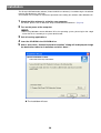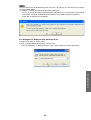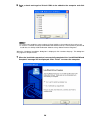
1
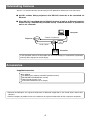
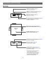
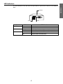
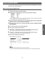
Introduction
Ethernet to RS-232C Network Converter
AN-LS1
Connections
MODEL
OPERATION MANUAL
Setup
• Please read this operation manual together
with the “IMPORTANT INFORMATION”
leaflet.
Using the Software
• Please read this operation manual carefully
to ensure correct use of the Ethernet to RS232C Network Converter.
• Prior to installation of this product, carry
out the appropriate network settings.
Appendix
Outstanding Features
AN-LS1 is a network converter for converting TCP/IP protocol on Ethernet to serial (RS-232C).
■ AN-LS1 enables Sharp projectors with RS-232C terminals to be controlled via
Ethernet.
■ Since AN-LS1 is provided with an RS-232C terminal as well as an Ethernet terminal,
control using a commercially available locally installed controller is possible as
well as via a network.
Computer
Projector
Control via network
Ethernet
LAN
Local control
Controller
In this operation manual, the illustration and the screen display are simplified for explanation,
and may differ slightly from actual display.
Accessories
Supplied Accessories
■ AC Adaptor
■ CD-ROM (Driver software and PDF operation manual)
■ IMPORTANT INFORMATION (Leaflet)
■ USA/Canada warranty card
■ International Software license (Paper)
• Microsoft and Windows are registered trademarks of Microsoft Corporation in the United States and/or other
countries.
• All other company or product names are trademarks or registered trademarks of their respective companies.
2
Contents
Outstanding Features ......................................................................................................................... 2
Accessories ........................................................................................................................................ 2
Part Names and Functions ................................................................................................................. 4
Main Body ................................................................................................................................ 4
LED Indicators .......................................................................................................................... 5
Wall Mount .......................................................................................................................................... 6
Connections
Overview ............................................................................................................................................ 7
Connecting to an Ethernet LAN ......................................................................................................... 8
Connecting to a Hub or Switch ................................................................................................ 8
Connecting to a Computer ....................................................................................................... 8
Connecting Devices ........................................................................................................................... 9
Connecting a Controller or a Computer ................................................................................... 9
Connecting a Projector ............................................................................................................ 9
Connecting the AC Adaptor .............................................................................................................. 10
Setup
Entering SETUP MENU .................................................................................................................... 11
When Connecting Using RS-232C .........................................................................................11
When Connecting Using Telnet .............................................................................................. 12
SETUP MENU Description ............................................................................................................... 13
SETUP MENU (Main Menu) .................................................................................................. 13
ADVANCED SETUP MENU ................................................................................................... 14
Basic Procedure ............................................................................................................................... 15
Setting of Each Item ......................................................................................................................... 18
Using the Software
About Sharp COM Redirection Software ......................................................................................... 25
Installation ........................................................................................................................................ 26
Starting ............................................................................................................................................. 29
Explanation of the Screen ................................................................................................................ 30
Operations ........................................................................................................................................ 31
Search and Add ...................................................................................................................... 31
Selecting Virtual COM Port .................................................................................................... 33
Add (Manual) .......................................................................................................................... 35
Refresh ................................................................................................................................... 37
Delete ..................................................................................................................................... 38
Password ............................................................................................................................... 40
Setting .................................................................................................................................... 42
OK/Cancel .............................................................................................................................. 43
Changing / Removing the Software ................................................................................................. 44
Appendix
Connecting Pin Assignments ........................................................................................................... 46
Troubleshooting ................................................................................................................................ 47
Specifications ................................................................................................................................... 52
Index ................................................................................................................................................. 53
3
Introduction
Introduction
Part Names and Functions
Main Body
TX/RX LED indicator (Page 5)
Lit when transmitting data.
10BASE-T Ethernet terminal (Page 8)
To connect to an Ethernet LAN.
LINK LED indicator (Page 5)
Lit when link is active.
RS-232C terminal for controller (Page 9)
To connect a commercially available
controller or computer.
TX/RX 10BASE-T LINK
RS-232C(CONTROLLER)
Wall mount screw holes (Page 6)
To be used for mounting AN-LS1 on a wall.
AN-LS1
POWER
POWER LED indicator (Page 5)
Lit when the power supply is on.
RS-232C(PROJECTOR)
INIT.
DC IN
RS-232C terminal for projector (Page 9)
To connect a projector.
DC power input (Page 10)
To connect an AC adaptor.
Initialize (INIT.) button (Page 51)
To initialize the settings for AN-LS1 to the
factory default settings.
• To initialize the settings for AN-LS1
to the factory default settings,
connect the plug for the AC adapter
to a wall outlet to supply the power
while pressing the Initialize (INIT.)
button using a pointed tool.
4
LED Indicators
POWER
LINK
TX/RX
Name
POWER
TX/RX
LINK
LED Color
LED Function
Green
Off
Orange
Off
Green
Off
Power is on.
Power is off.
Network packets are being transmitted or received.
No network packet is being transmitted or received.
AN-LS1 is connected to the network.
Ethernet cable is disconnected.
5
Introduction
The LED indicators at the side and on the top of AN-LS1 represent the contents in the following
table.
Wall Mount
You will find it convenient to mount AN-LS1 on the wall, using two screws, as indicated below.
1
Screw two screws (not included) into the wall 96.5 mm apart.
The heads of the screws should be 5-7 mm in diameter, and the shafts should be 3 mm in diameter.
(It is recommended to use screws of 12 mm or more in length.) Do not screw the screws in all the
way—leave a space of about 4 mm to allow room for sliding AN-LS1’s ears between the wall and
the screws.
5-7 mm
96.5 mm
2
Insert the two screw heads through the large parts of the keyhole shaped apertures,
and then slide AN-LS1 downwards, as indicated.
3
For added stability, simply tighten the two screws.
TX/RX 10BASE-T LINK RS-232C(CONTROLLER)
TX/RX 10BASE-T LINK RS-232C(CONTROLLER)
AN-LS1
AN-LS1
POWER
POWER
RS-232C(PROJECTOR)
INIT.
DC IN
RS-232C(PROJECTOR)
INIT.
• To remove AN-LS1 from the wall mount, simply reverse steps 2 and 3 above.
6
DC IN
Overview
Use the following procedure for connection of AN-LS1.
1
2
Connect AN-LS1 to an Ethernet LAN. (Page 8)
3
Connect the AC adaptor. (Page 10)
Connect devices to AN-LS1. (Page 9)
• Connect a commercially available controller or computer.
• Connect a projector.
Computer
Controller
Ethernet
LAN
2
2
Projector
7
Connections
or
1
3
Connecting to an Ethernet LAN
Connect AN-LS1 to a hub or a computer using a Category 5 cable.
• It is necessary to perform computer setting according to the network environment in advance.
• Default IP address and subnet mask of AN-LS1 are as follows:
IP address : 192.168.150.2
Subnet mask : 255.255.255.0
• When using AN-LS1 by connecting to an existing Ethernet LAN, and if there is any problem with
the above settings, change settings such as IP address by creating an independent network
without connecting to the existing Ethernet LAN or by connecting a computer to the RS-232C
(CONTROLLER) terminal.
After that, connect to the existing Ethernet LAN.
To Ethernet 10BASE-T or
100BASE-TX terminal
Hub
Category 5 cable (sold separately)
or
Computer
Connecting to a Hub or Switch
For most applications, you will simply plug one end of your Category 5 cable into the10BASE-T
terminal of AN-LS1. In this case, you should use a standard straight-through Category 5 cable, which
is readily available from many commercial vendors. If necessary, however, you can make your own
cable by referring to the following cable wiring diagram.
Straight-Through Cable
Hub
AN-LS1
RJ-45 Jack
Connector
Tx+
TxRx+
Rx-
RJ-45 Plug
Cable Wiring
1
2
3
6
1
2
3
6
RJ-45 Jack
Connector
Tx+
TxRx+
Rx-
Connecting to a Computer
In some cases, such as when configuring drivers and software, you will find it convenient to hook ANLS1 directly to your computer’s Ethernet terminal. To do this, you will need to use a cross-over Category
5 cable. This type of Category 5 cable is harder to find, although you can make your own cable by
referring to the following cable wiring diagram.
Cross-Over Cable
AN-LS1
RJ-45 Jack
Connector
Tx+
TxRx+
Rx-
PC Network adaptor
RJ-45 Plug
Cable Wiring
1
2
3
6
1
2
3
6
8
RJ-45 Jack
Connector
Tx+
TxRx+
Rx-
Connecting Devices
Connect a commercially available controller or computer and a projector to AN-LS1.
Connecting a Controller or a Computer
In the case of controlling a projector via RS-232C as well as via the Ethernet LAN, connect a
commercially available controller or computer to the RS-232C (CONTROLLER) terminal.
RS-232C (CONTROLLER)
or
Computer
RS-232C serial control
cable
(commercially available)
• For connection procedures for each device, please refer to the operation manual for each device.
• Make sure not to connect a controller or a computer to the RS-232C (PROJECTOR) terminal.
• Set as follows for the Port settings for RS-232C.
Baud Rate : Set the same value as AN-LS1. (Page 11)
Data Length : 8 bits
Parity Bit
: None
Stop Bit
: 1 bit
Flow Control : None
• In the case of connecting to a controller, use a suitable cable for the RS-232C cable.
• In the case of connecting to a computer, use a cross-over type cable for the RS-232C cable.
Connecting a Projector
Connect a projector to the RS-232C (PROJECTOR) terminal.
RS-232C (PROJECTOR)
To RS-232C terminal
Projector
RS-232C serial control
cable
(commercially available)
• For connection procedures for a projector, please refer to the operation manual for the projector.
• In the case of connecting to a projector, use a cross-over type cable for the RS-232C cable.
9
Connections
To RS-232C terminal
Controller
(commercially available)
Connecting the AC Adaptor
Take the following steps to connect AN-LS1’s AC adaptor.
1
2
Plug the AC adaptor’s DC plug into AN-LS1’s DC IN jack.
Plug the AC adaptor into wall outlet.
To wall outlet
• There is no on/off switch. AN-LS1 turns on as soon as the connected AC adaptor is plugged into
a wall outlet. The POWER LED indicator on AN-LS1’s top panel will light green to indicate that it
is receiving power.
•
•
•
•
•
•
CAUTION
The AC adaptor may interfere with reception if used near a radio.
Prevent flammables, liquids, and metal objects from entering the AC adaptor.
The AC adaptor is a sealed unit. Do not attempt to open or modify it.
Do not damage, drop, or subject the AC adaptor to vibration.
Do not leave the AC adaptor in direct sunlight.
Avoid using the AC adaptor in humid or extremely hot places.
10
Entering SETUP MENU
Connect AN-LS1 to a computer using RS-232C or Telnet, and open the “SETUP MENU” on the computer
to carry out various settings for AN-LS1.
When Connecting Using RS-232C
1
2
Launch general purpose terminal emulator.
Set settings for the RS-232C port of the terminal emulator as follows.
Baud Rate
Data Length
Parity Bit
Stop Bit
Flow Control
: *9600 bps
: 8 bit
: None
: 1 bit
: None
* This is the default value. If the value of Baud Rate for AN-LS1 has been changed, set Baud Rate
here according to the changed value on AN-LS1. (Page 19)
3
Connect the plug for the AC adapter to a wall outlet to supply the power while holding
down the “A” (or “a”) key on the terminal keyboard.
4
Keep holding down the “A” (or “a”) key for more than 3 seconds. “Setup Menu Enable”
will be displayed.
5
6
7
Press the return key on the terminal keyboard.
Input “setup” and press the return key.
(If a user name has not yet been set, just press the return key.)
8
“Password:” is displayed. Input the password and press the return key.
(If a password has not yet been set, just press the return key.)
9
Input “setup” and press the return key.
| SETUP MENU will be displayed.
SETUP MENU
[1]IP Address
[2]Subnet Mask [3]Default Gateway
[4]User Name
[5]Password
[6]RS-232C Baud Rate [7]Unit Name
[A]Advanced Setup
[D]Disconnect All
[V]View All Setting
[S]Save & Quit [Q]Quit Unchanged
setup>
• User name and password are not set in the initial settings.
• If the user name or password is entered incorrectly three times, SETUP MENU will be quit.
11
Setup
“User Name:” is displayed. Input the user name and press the return key.
When Connecting Using Telnet
1
2
Click “Start” from the Windows desktop and select “Run”.
Enter “telnet 192.168.150.2” in the text box that opens up.
(If the IP address of the unit is 192.168.150.2.)
3
4
Click “OK”.
“User Name:” is displayed. Input the user name and press the return key.
(If a user name has not yet been set, just press the return key.)
5
“Password:” is displayed. Input the password and press the return key.
(If a password has not yet been set, just press the return key.)
6
Input “setup” and press the return key.
| SETUP MENU will be displayed.
SETUP MENU
[1]IP Address
[2]Subnet Mask
[4]User Name
[5]Password
[6]RS-232C Baud Rate [7]Unit Name
[A]Advanced Setup
[V]View All Setting
[S]Save & Quit
[3]Default Gateway
[D]Disconnect All
[Q]Quit Unchanged
setup>
• If the IP address has been changed, be sure to enter the correct IP address.
• User name and password are not set in the initial settings.
• If the user name or password is entered incorrectly three times, SETUP MENU will be quit.
12
SETUP MENU Description
SETUP MENU (Main Menu)
SETUP MENU
[1]IP Address
[2]Subnet Mask
[4]User Name
[5]Password
[6]RS-232C Baud Rate [7]Unit Name
[A]Advanced Setup
[V]View All Setting
[S]Save & Quit
[3]Default Gateway
[D]Disconnect All
[Q]Quit Unchanged
setup>
[1] IP Address (Factory default setting : 192.168.150.2)
IP address settings. (Page 18)
[2] Subnet Mask (Factory default setting : 255.255.255.0)
Subnet mask settings. (Page 18)
[3] Default Gateway (Factory default setting : Not Used)
Default gateway settings. (Page 18)
[4] User Name (Factory default setting : Not Required)
Setting of user name for security protection. (Page 19)
[5] Password (Factory default setting : Not Required)
Setting of password for security protection. (Page 19)
[7] Unit Name (Factory default setting : AN-LS1)
It is possible to assign a unit name. (Page 20)
[A] Advanced Setup
Enters ADVANCED SETUP MENU. (Page 20)
[D] Disconnect All
Disconnect all connections. (Page 20)
[V] View All Setting
Displays all setting values. (Page 15)
Can also be used with advanced menu.
[S] Save & Quit
Save set values and quit menu. (Page 17)
[Q] Quit Unchanged
Quit menu without saving setting values. (Page 17)
13
Setup
[6] RS-232C Baud Rate (Factory default setting : 9600 bps)
Baud rate settings for the RS-232C terminals. (Page 19)
ADVANCED SETUP MENU
******************** ADVANCED SETUP MENU ***********************
[1]Auto Logout Time [2]COM Redirect Port [3]Busy Reply
[4]Input Hold Time
[5]Network Ping Test
[6]Accept IP Addr(1) [7]Accept IP Addr(2) [8]Accept IP Addr(3)
[9]Accept All IP Addr [0]Port for Search
[!]Restore Default Setting
[Q]Return to Main Menu
advanced>
[1] Auto Logout Time (Factory default setting : 5 minutes)
Setting of time until automatic disconnection of network connection. (Page 21)
[2] COM Redirect Port (Factory default setting : 10002)
Setting of TCP port No. capable of connecting using Sharp COM Redirection Software. (Page 21)
[3] Busy Reply (Factory default setting : ERR + <CR> code)
When separate devices are connected to the two control terminals (RS-232C (CONTROLLER)
and 10BASE-T), it is not possible to use one control terminal while data is being transmitted using
the other control terminal.
This setting is for operation of the control terminal that cannot be used.
(Page 22)
[4] Input Hold Time (Factory default setting : 1000 milliseconds)
Changing value for Input Hold Time when a response is not returned from a projector within a set
time while separate devices are connected to the two control terminals (RS-232C (CONTROLLER)
and 10BASE-T). (Page 22)
[5] Network Ping Test
It is possible to confirm that a network connection between AN-LS1 and a computer etc. is working
normally. (Page 23)
[6]
[7]
[8]
[9]
Accept IP Addr(1)
Accept IP Addr(2)
Accept IP Addr(3)
Accept All IP Addr (Factory default setting : Accept All)
For improved security, it is possible to set up to three IP addresses allowing connection to ANLS1. Set IP addresses can be cancelled using [9] Accept All IP Addr. (Page 23)
[0] Port for Search (Factory default setting : 5006)
Setting for port number used when Sharp COM Redirection Software searches for AN-LS1. (Page
24)
[!] Restore Default Setting
Restores all setting values that can be set using the menu to the default state.
(Page 24)
[Q] Return to Main Menu
Return to the main SETUP MENU. (Page 24)
14
Basic Procedure
Enter number or symbol of item to be selected on the “SETUP MENU”. When setting, input the details
to be set. Setting is carried out one item at a time, and saved at the end.
View Setting Detail List ([V]View All Setting)
Displays all setting values.
▼ The SETUP MENU
———————— S E T U P M E N U ——————————
[1]IP Address
[2]Subnet Mask [3]Default Gateway
[4]User Name
[5]Password
[6]RS-232C Baud Rate [7]Unit Name
[A]Advanced Setup
[D]Disconnect All
[V]View All Setting
[S]Save & Quit [Q]Quit Unchanged
15
Enter “v” and press the return key.
Display the current setting detail
list.
Setup
setup>v
Model Name
: AN-LS1
Unit Name
: AN-LS1
MAC Address
: 08:00:1f:b1:b7:74
IP Address
: 192.168.150.2
Subnet Mask
: 255.255.255.0
Default Gateway : Not Used
RS-232 Baud Rate : 9600 bps
Password
: Not Required
**********(Advanced Status)**********
COM Redirect Port : 10002
Accept IP Address : Accept All
Busy Reply
: ERR+<CR> code
Input Hold Time
: 1000 milliseconds
Auto Logout Time : 5 minutes
Port for Search
: 5006
Set Items
(e.g.) When setting IP Address (change from 192.168.150.2 to 192.168.150.3)
▼ The SETUP MENU
———————— S E T U P M E N U ——————————
[1]IP Address
[2]Subnet Mask
[3]Default Gateway
[4]User Name
[5]Password
[6]RS-232C Baud Rate [7]Unit Name
[A]Advanced Setup
[D]Disconnect All
[V]View All Setting
[S]Save & Quit
[Q]Quit Unchanged
setup>1
IP Address
: 192.168.150.2
Please Enter
: 192.168.150.3
(change)
—> 192.168.150.3
———————— S E T U P M E N U ——————————
[1]IP Address
[2]Subnet Mask [3]Default Gateway
[4]User Name
[5]Password
[6]RS-232C Baud Rate [7]Unit Name
[A]Advanced Setup
[D]Disconnect All
[V]View All Setting
[S]Save & Quit
[Q]Quit Unchanged
setup>v
Model Name
: AN-LS1
Unit Name
: AN-LS1
MAC Address
: 08:00:1f:b1:b7:74
IP Address
: 192.168.150.3
Subnet Mask
: 255.255.255.0
Default Gateway
: Not Used
RS-232C Baud Rate: 9600 bps
Password
: Not Required
**********(Advanced Status)**********
COM Redirect Port : 10002
Accept IP Address : Accept All
Busy Reply
: ERR+<CR> code
Input Hold Time
: 1000 milliseconds
Auto Logout Time : 5 minutes
Port for Search
: 5006
Enter “1” (number of item to be
set), and press the return key.
Display current IP address.
Enter IP address to be set and
press the return key.
Display IP address after
change.
Enter “v” and press the return
key to verify setting detail list.
IP address is being changed.
• Verification of setting detail list can be omitted.
• Setting details are not effective until they have been saved. (Page 17)
• If an invalid number is entered, an error message (“Parameter Error!”) will be displayed.
16
Quit
Save settings and quit. ([S]Save & Quit)
Save set values and quit menu.
▼ The SETUP MENU
———————— S E T U P M E N U ——————————
[1]IP Address
[2]Subnet Mask [3]Default Gateway
[4]User Name
[5]Password
[6]RS-232C Baud Rate [7]Unit Name
[A]Advanced Setup
[D]Disconnect All
[V]View All Setting
[S]Save & Quit
[Q]Quit Unchanged
setup>s
All Connection will be disconnect.
Continue(y/n)? y
Apply New setting...Done.
Enter “s” and press the return key.
Enter “y” and press the return key.
Quit without saving settings. ([Q]Quit Unchanged)
Quit menu without saving setting values.
▼ The SETUP MENU
setup>q
Quit Without Saving(y/n)? y
Setting Unchanged.
Setup
———————— S E T U P M E N U ——————————
[1]IP Address
[2]Subnet Mask [3]Default Gateway
[4]User Name
[5]Password
[6]RS-232C Baud Rate [7]Unit Name
[A]Advanced Setup
[D]Disconnect All
[V]View All Setting
[S]Save & Quit
[Q]Quit Unchanged
Enter “q” and press the return key.
Enter “y” and press the return key.
17
Setting of Each Item
The setting procedure for each item will be explained. For the basic procedure, please refer to page
15.
IP Address Setting ([1]IP Address)
Setting of IP address.
setup>1
IP Address
:192.168.150.2
Please Enter
:192.168.150.3
(change)
—> 192.168.150.3
Enter “1” and press the return key.
Enter numerical value to be set
and press the return key.
Display IP address after
change.
Subnet Mask Setting ([2]Subnet Mask)
Setting subnet mask.
Enter “2” and press the return key.
setup>2
Subnet Mask
:255.255.255.0
Please Enter
:255.0.0.0
(change)
—> 255.0.0.0
Enter numerical value to be set
and press the return key.
Display subnet mask after
change.
Default Gateway Setting ([3]Default Gateway)
Setting default gateway.
setup>3
note: “0.0.0.0” means “Using no default gateway.”
Gateway Address :0.0.0.0
Please Enter
:192.168.150.1
(change)
—> 192.168.150.1
Enter “3” and press the return key.
Enter numerical value to be set
and press the return key.
Display gateway address after
change.
• If operations on this page are performed while changing the setting for AN-LS1 via Telnet, there may be
situations where AN-LS1 cannot be connected depending on the network setting for the computer for control
since the set values for IP Address, Subnet Mask or Gateway are restored to the initial state.
18
User Name Setting ([4]User Name)
Carrying out security protection using user name.
Enter “4” and press the return key.
setup>4
User Name
:
Please Enter
: an-ls1
(change)
—> an-ls1
Enter user name and press the
return key.
Display set user name.
• User name can be up to 8 characters.
• In the initial state, user name is not set.
Password Setting ([5]Password)
Carrying out security protection using password.
Enter “5” and press the return key.
setup>5
Password
:
Please Enter
: sharppj
(change)
—> sharppj
Enter password and press the
return key.
Display set password.
Setup
• Password can be up to 8 characters.
• In the initial state, the password is not set.
RS-232C Baud Rate Setting ([6]RS-232C Baud Rate)
Setting of baud rate for RS-232C (CONTROLLER and PROJECTOR) terminals.
Enter “6” and press the return key.
setup>6
note: It sets both RS-232C (CONTROLLER) and RS-232C (PROJECTOR).
0 ... 9600 bps
1 ... 38400 bps
2 ... 115200 bps
Select and enter the number 0, 1,
Baud Rate Select[0-2] :1
or 2 and press the return key.
RS-232C Baud Rate : 38400 bps
Display set baud rate.
• Baud Rates for the RS-232C (CONTROLLER) terminal and the RS-232C (PROJECTOR) terminal
cannot be set to different values.
19
Unit Name Setting ([7]Unit Name)
It is possible to assign a unit name.
When searching using Sharp COM Redirection Software, it is possible to verify a communication
destination using the unit name.
Enter “7” and press the return key.
setup>7
Unit Name
: AN-LS1
Please Enter
: My An-ls1
(change)
—> My An-ls1
Enter unit name.
Display set unit name.
• Unit name can be up to 12 characters.
Disconnecting All Connections ([D]Disconnect All)
It is possible to disconnect all the TCP/IP connections currently recognized by AN-LS1. Even if the
COM Redirect port is fixed in the Busy status due to a problem, it is possible to force the Ready status
back by carrying out this disconnection. (Page 51)
setup>d
Disconnect All Connections(y/n)?y
Now Disconnecting...
Enter “d” and press the return key.
Enter “y” and press the return key.
• If Disconnect All is performed while Sharp COM Redirection Software or the Telnet menu is in
use, Sharp COM Redirection Software will be forcibly terminated or the connection via Telnet will
be disconnected.
Entering ADVANCED SETUP MENU ([A]Advanced Setup)
Enters ADVANCED SETUP MENU.
setup>a
Enter “a” and press the return key.
****************** ADVANCED SETUP MENU *********************
[1]Auto Logout Time [2]COM Redirect Port [3]Busy Reply
[4]Input Hold Time
[5]Network Ping Test
[6]Accept IP Addr(1) [7]Accept IP Addr(2) [8]Accept IP Addr(3)
[9]Accept All IP Addr [0]Port for Search
[!]Restore Default Setting
[Q]Return to Main Menu
advanced>
20
The followings are descriptions of the ADVANCED SETUP MENU.
Setting Automatic Logout Time (ADVANCED[1]Auto Logout Time)
If there is no input after a fixed time, AN-LS1 automatically disconnects network connection using the
Auto Logout function. It is possible to set the time until AN-LS1 is automatically disconnected in units
of a minute (from 1 to 65535 minutes).
advanced>1
Valid range
: 0 to 65535 (minute)
note: if you enter “0”, auto logout function will be disable.
Auto Logout Time : 5
Please Enter
: 15
(change)
—> 15
Enter “1” and press the return key.
Enter numerical value and press
the return key.
Display set numerical value.
• If the set value is made 0, the Auto Logout function is disabled.
COM Redirect Port Setting (ADVANCED[2]COM Redirect Port)
Setting of TCP port number capable of connecting using Sharp COM Redirection Software.
Can be set in the range of 1025 to 65535.
Enter numerical value and press
the return key.
Display set numerical value.
21
Setup
Enter “2” and press the return key.
advanced>2
Valid range
:1025 to 65535
COM Redirect Port :10002
Please Enter
:10005
(change)
—> 10005
Busy Reply Setting (ADVANCED[3]Busy Reply)
The input terminals of AN-LS1 can be RS-232C (CONTROLLER) and 10BASE-T. Respective input
terminals can be connected to separate devices, but in actual if one of the terminals is being used the
other terminal cannot be used.
When data is being transmitted using one input terminal, it is not possible to use the other input
terminal until communication using the first terminal is completed.
This setting is for operation of the input terminal that cannot be used.
It is possible to select whether ERR is returned or nothing is returned when a return (CR:0x0d) code
is sent to the terminal that cannot be used.
advanced>3
When input is busy, return
1 ... ERR+<CR> code
2 ... none (ignore busy input)
Busy Reply Select[1-2] : 2
Busy Reply
: none (ignore busy input)
Enter “3” and press the return key.
Select and input number 1 or 2
and press the return key.
Display Setting content.
Input Hold Time Setting (ADVANCED[4]Input Hold Time)
The input terminals of AN-LS1 can be RS-232C (CONTROLLER) and 10BASE-T. Respective input
terminals can be connected to separate devices, but while one is in use, the other is put into an
unusable state, and it is possible to protect communication content. The minimum requirement for the
Input Hold Time is an interval from transmission of data until a response returned from a projector is
complete.
When a response is not returned from the projector within a set time, it is possible to reliably receive
a response by extending the Input Hold Time.
Also when the time of protection for one device is too long, there may be cases where the other device
cannot establish communication as desired. In this case, set Input Hold Time to be small so that both
communications can be carried out without any problem.
Setting can be carried out in 100 ms units, from 100 ms to 40000 ms.
advanced>4
Valid range
Input Hold Time
Please Enter
(change)
—>
Enter “4” and press the return key.
: 100 to 40000 (milliseconds)
: 1000
: 5000
5000
Enter numerical value and press
the return key.
Display set numerical value.
22
Carrying out Network Ping Test (ADVANCED[5]Network Ping Test)
It is possible to confirm that a network connection between AN-LS1 and a computer etc. is working
normally.
advanced>5
Ping dest IP addr :192.168.150.1
Please Enter
:192.168.150.152
(change)
—> 192.168.150.152
32 bytes from 192.168.150.152: icmp_seq = 1, time = 0 ms
32 bytes from 192.168.150.152: icmp_seq = 2, time = 0 ms
32 bytes from 192.168.150.152: icmp_seq = 3, time = 0 ms
32 bytes from 192.168.150.152: icmp_seq = 4, time = 0 ms
Enter “5” and press the return key.
Enter IP address of device to be
tested and press the return key.
Display entered IP address.
Display test result.
• If the return key is pressed without entering an IP address, the Ping destination IP address used
before is entered.
• If there is a fault with the connection, “Error: No answer” is displayed after a 5 second retry. In
this case, please confirm the settings for AN-LS1 and the computer, and contact your network
administrator.
Setting of Accept IP Address (ADVANCED[6]Accept IP Addr(1) - [8]Accept IP Addr(3))
It is possible to improve security of AN-LS1 by allowing connection from only a prescribed IP address.
It is possible to set up to three IP addresses allowing connection to AN-LS1.
Enter numerical value and press
the return key.
Display set numerical value.
• To invalidate the Accept IP Address being currently set, enter “0.0.0.0”.
• If there is one or more Accept IP Addr being set, no connections are allowed from IP addresses
that are not yet set. They can be cancelled using [9]Accept All IP Addr.
Accepting All IP Addresses (ADVANCED[9]Accept All IP Addr)
Removes IP addresses set with “Accept IP Addr”.
Enter “9” and press the return key.
advanced>9
Accept All IP Addresses(y/n)? y
Enter “y” and press the return key.
• At the point in time where “y” was entered, the numerical values for Accept IP Addr(1)-(3) are
reset to ”0.0.0.0”.
• If “n” is entered, settings are not altered.
23
Setup
Enter “6”, “7” or “8” and press
the return key.
advanced>6
Accept IP Addr(1) : 0.0.0.0
Please Enter
: 192.168.150.152
(change)
—> 192.168.150.152
Setting of Port for Search (ADVANCED[0]Port for Search)
Sets the port number used when Sharp COM Redirection Software searches for AN-LS1.
advanced>0
Please Enter Port Number for Search from Computer.
Valid range
: 1025 to 65535
Port for Search : 5006
Please Enter
: 5004
(change)
—> 5004
Enter “0” and press the return key.
Enter numerical value and press
the return key.
Display set numerical value.
Return to Default Settings (ADVANCED[!]Restore Default Setting)
Returns all setting values that can be set using the menu to the default state.
Same operation as turning on the power while holding down the INIT. (Initialize) button on the unit.
Enter “!” and press the return key.
advanced>!
Restore All Setting to Default(y/n)? y
— User Setting Initialized —
Enter “y” and press the return key.
• If this operation is performed while changing the setting for AN-LS1 via Telnet, there may be
situations where AN-LS1 cannot be connected depending on the network setting for the computer
for control since the set values for IP Address, Subnet Mask, Gateway and etc. are restored to
the initial state.
Return to Main Menu (ADVANCED[Q]Return to Main Menu)
Returns to the main SETUP MENU.
advanced>q
———————— S E T U P M E N U ——————————
[1]IP Address
[2]Subnet Mask [3]Default Gateway
[4]User Name
[5]Password
[6]RS-232C Baud Rate [7]Unit Name
[A]Advanced Setup
[D]Disconnect All
[V]View All Setting
[S]Save & Quit [Q]Quit Unchanged
setup>
24
Enter “q” and press the return key.
About Sharp COM Redirection Software
Using Sharp COM Redirection Software, it is possible to create a “Virtual COM” port. If general
application software outputs data to this Virtual COM port, Sharp COM Redirection Software will
transfer the data to AN-LS1 which is on a network.
With this system, control for a projector conventionally carried out via a COM port can be carried out
via an Ethernet LAN without changing control software.
Computer
Application
software
Sharp COM
Redirection
Software
(Virtual COM)
COM port
(RS-232C)
Ethernet
port
Projector
Ethernet
LAN
AN-LS1
This software supports the following Operating Systems:
Windows 98, 98SE, Me, 2000 Professional, XP Home Edition, XP Professional Edition.
* Operations are confirmed with English versions of those Windows operating systems only.
To Users of Sharp Advanced Presentation Software
25
Using the Software
When using this software via the Virtual COM port and/or the RS-232C (PROJECTOR) terminal,
the following functions cannot be used:
• Presentation Transfer
• Capture & Transfer
• Quick Transfer
Installation
The Sharp COM Redirection software (Virtual COM Driver software) is installed using the installation
program provided on the CD-ROM.
This manual uses examples to explain the operations for installing the software under Windows XP.
1
Check that this software is suited for your computer.
For details, please refer to “About the Sharp COM Redirection Software”. (Page 25)
2
Turn on the power of the computer.
• When using Windows 2000 or Windows XP as the operating system, please log in with a login
name that has the authority of a system administrator.
3
4
5
Quit all running applications.
Insert the CD-ROM in the CD-ROM drive.
After a short while, “Choose Destination Location” dialog will be displayed. Assign
the destination folder for installation and click “Next>”.
| The installation will start.
26
• Please change the destination only when necessary. (In general, it is not necessary to change
the destination folder.)
• If “Cancel” is clicked, “Exit Setup” dialog will be displayed.
• If “Yes” is clicked, the Sharp COM Redirection Software Driver is not installed. If you want to
install later, run Sharp COM Redirection Software using “Add or Remove Programs”.
• Click “No” to continue the installation.
If no dialog box is displayed after waiting a while:
(1) Select “Run” from the “Start” menu.
(2) Input “R:\SOFTWARE\SETUP.EXE” and click “OK”.
(If the CD-ROM drive is different from the R drive, please input the correct drive name.)
Using the Software
27
6
Enter a check mark against Virtual COMs to be added to the computer and click
“OK”.
• It is necessary to add the same number of Virtual COMs as the number of these units used.
• If “Cancel” is clicked, the Sharp COM Redirection Software Driver is not installed. If you want to
install later, run Sharp COM Redirection Software using “Add or Remove Programs”.
When the “Hardware Installation” dialog box is displayed, click “Continue Anyway”. This dialog box
may appear a couple of times.
7
When the installation procedure is successfully completed, the “InstallShield Wizard
Complete” message will be displayed. Click “Finish” to restart the computer.
28
Starting
Launch Sharp COM Redirection Software.
1
Launch by double clicking the Sharp COM Redirection Software icon in the Control
Panel.
• Switch the display of the Control Panel to Classic View.
| Open configuration dialog.
Using the Software
29
Explanation of the Screen
▼ Configuration dialog
1
4
5
6
2
3
8
9
7
1 List display area
List display of states of all units recognizing Sharp COM Redirection Software, and allocation
states of Virtual COM ports. (Page 32)
2 Search
Searches for units, and adds to the list display. (Page 31)
3 Setting
Setting of computer data communication port number and search port number. (Page 42)
4 Add
Manually adds an unit to list display. (Page 35)
5 Delete
Deletes the unit selected within the list display. (Page 38)
6 Password
Setting for password used when connecting to the unit. (Page 40)
7 OK
Defines content of setting or change and closes configuration dialog. (Page 43)
8 Refresh
Changes list display to latest information. (Page 37)
9 Cancel
Cancels content of setting or change and closes configuration dialog. (Page 43)
30
Operations
Search and Add
Searches for units on a network and adds to the list display.
1
Click “Search”.
| “Search tool” dialog is displayed, and search for units existing on the network is automatically
executed.
Using the Software
• If you want to re-execute a search, click “Search”.
• In cases such as when “network security monitoring software” is installed on the computer, or
when a firewall has been installed on the network system, it may be impossible to communicate
using the current search port number. In this case, please click “Setting”, and change the search
port number. (Page 42)
31
2
Click the unit to be added to list display.
3
Click “Add to List”.
| Added to list display after carrying out communication to each selected unit.
32
Selecting Virtual COM Port
Selecting Virtual COM port used when communicating with AN-LS1.
1
Click the “Virtual COM” column.
| The “Virtual COM” column will become a pull-down selectable menu.
Using the Software
33
2
Click and select the “Virtual COM” number to be used for communication with AN-LS1.
3
Click on an area outside the “Virtual COM” pull down menu.
| “Virtual COM” number is changed.
34
Add (Manual)
Adding units to the list display manually in cases such as when units cannot be found, even by searching.
1
Click “Add”.
| “Add Unit” dialog will be displayed.
Using the Software
35
2
Enter IP address and click “OK”.
| Unit will be added.
36
Refresh
Changing the list display content to the latest state.
1
Click “Refresh”.
| Model Name, Unit Name and Status will be updated to the latest information.
Ready
: Communication with AN-LS1 is possible.
No Response : Communication with AN-LS1 is not possible. Please check connection. (Page 47)
Busy
: Already connected from another computer.
• “Busy” may sometimes be displayed even when a network connection has been disconnected
with a normal procedure. (For more details, please refer to page 51.)
37
Using the Software
About Status
Delete
Deleting an unit from the list display.
1
Click on the unit to be deleted.
2
Click “Delete”.
38
| A confirmation dialog will be displayed.
• If you do not want to delete the unit, click “Cancel”.
3
Click “Yes”.
| The unit to be deleted will be removed from the list display.
Using the Software
39
Password
If units with user name/password set appear within the list display, the user name/password for those
units must be entered.
Enter when communicating with AN-LS1
When communicating with AN-LS1, when a dialog prompting input of user name/password is displayed
as shown below, enter the user name and password set at the unit side, enter a check mark in the
“Save this password” box, as required, and click “OK”.
Inputting in advance
It is possible to enter the user name/password in advance.
1
Click the subject unit.
40
2
Click “Password”.
| A dialog prompting entry of user name/password will be displayed.
Enter the user name and password being set to the unit and click “OK”.
41
Using the Software
3
Setting
Setting of computer data communication port number and search port number.
1
Click “Setting”.
| “Setting” dialog will be displayed.
2
Enter “Search Port” number and “Data Port” number and click “OK”.
Search Port : Enter port number used for searching AN-LS1. (1025 to 65535)
Data Port : Enter port number used for communicating with AN-LS1. (*1025 to 65535)
* Values to be entered vary according to the environment setting of the computer. For details,
contact your network administrator.
• In cases such as when “network security monitoring software” is installed on the computer, or
when a firewall has been installed on the network system, it may be impossible to communicate
using the current search port number. In this case, please change the port number for search
and/or specify the range of data port numbers. There may be cases where the data ports have
been used by OS or other software, so specify a wider range of data ports.
42
OK/Cancel
When defining content of setting or change, click “OK” when closing the “Configuration dialog”.
When canceling content of setting or change, click “Cancel” when closing the “Configuration dialog”.
Using the Software
43
Changing / Removing the Software
Be sure to always uninstall the Sharp COM Redirection Software, when reinstalling the Sharp COM
Redirection Software or an updated version.
1
2
Quit all running applications.
Click the “Start” menu, “Settings”, and then “Control Panel”.
(If your operating system is Windows XP, click the “Start” button, and then “Control Panel”.)
3
Click the “Add or Remove Programs” icon.
4
Select “Sharp COM Redirection Software”, and then click “Change/Remove”.
44
5
Select “Modify”, “Repair” or “Remove”, and then click “Next>” on the “Welcome”
dialog box.
■“Modify”
For adding or removing Virtual COMs from the computer. The dialog box is displayed and there
you can select which Virtual COMs you want to add or remove.
■“Repair”
For reinstalling software already in the computer.
■“Remove”
For uninstalling (removing) software already installed.
Using the Software
6
Follow the instructions on the screen.
45
Connecting Pin Assignments
RS-232C Terminal: 9-pin D-sub male connector
1
6
5
9
Pin No.
1
2
3
4
5
6
7
8
9
Signal
CD
RD
SD
ER
SG
Name
I/O
Receive Data
Send Data
Input
Output
Signal Ground
RS
CS
CI
10BASE-T terminal: 8-pin RJ-45 connector
Pin No.
1
2
3
4
8
Signal
TX+
TXRX+
NC
1
46
Pin No.
5
6
7
8
Signal
NC
RXNC
NC
Reference
Not connected
Connected to internal
Connected to internal
Not connected
Connected to internal
Not connected
Connected to internal
Connected to internal
Not connected
circuit
circuit
circuit
circuit
circuit
Troubleshooting
The POWER indicator on the top panel does not light green.
\ Check if the power plug of the AC adaptor is disconnected from the wall outlet. (Page 10)
\ Check that DC IN is connected firmly with the cord from the AC adaptor. (Page 10)
Communication cannot be established with AN-LS1 or a projector.
When connecting AN-LS1 using serial-connection
\ Check that the RS-232C terminal of AN-LS1 and a computer or the serial port of the projector are
connected correctly. (Page 9)
\ Check that the RS-232C cable is a cross-over cable. (Page 9)
\ Check that a commercially available controller or computer is connected to the RS-232C
(CONTROLLER) terminal.
\ Check that the projector is connected to the RS-232C (PROJECTOR) terminal.
\ Check that the RS-232C port setting for AN-LS1 corresponds to the setting for the computer or the
projector. (Page 9)
When connecting AN-LS1 to a computer using network (LAN)-connection
\ Check that the cable’s connector is firmly inserted in the 10BASE-T terminal of AN-LS1.
\ Check that the cable is firmly inserted into a LAN port for a computer or a network device such as
a hub.
\ Check that the LAN cable is a Category 5 cable.
\ Check that the LAN cable is a cross-over cable when connecting AN-LS1 to a computer directly.
\ Check that the LAN cable is a straight-through cable when connecting AN-LS1 with a network
device such as a hub.
\ Check that the power supply is turned on for the network device such as a hub between AN-LS1
and a computer.
\ Check that the RS-232C (PROJECTOR) terminal and the serial port for the projector are connected
correctly.
\ Check that the RS-232C cable is a cross-over cable.
\ Check that the RS-232C port setting for AN-LS1 corresponds to the setting for the projector.
Check that Sharp COM Redirection Software is installed correctly.
1. Click “Start” → “Control Panel”.
2. Double-click “System”.
3. Select “Hardware” tab and click “Device Manager”.
4. Double-click “Ports (COM & LPT)”.
If the Sharp COM Redirection Software icon is shown, Sharp COM Redirection Software has been
installed.
47
Appendix
If there is a yellow exclamation mark (!) or question mark (?) on the Sharp COM Redirection Software
icon, there is a possibility that the installation has failed, COM numbers are duplicated or there is a
conflict with another driver resource.
In such a case, it is necessary to delete Sharp COM Redirection Software once and then reinstall it.
Check the network settings for the computer and AN-LS1.
\ Check the following network settings for AN-LS1.
• IP address
\ Check that the IP address for AN-LS1 is not duplicated on the network.
• Subnet mask
\ When the gateway setting for AN-LS1 is “0.0.0.0” (Not Used), or the gateway setting for ANLS1 and the default gateway setting for the computer are the same:
• The subnet masks for AN-LS1 and the computer should be the same.
• The IP address parts shown by the subnet mask for AN-LS1 and the computer should be
the same.
(Example)
When the IP address is “192.168.150.2” and the subnet mask is “255.255.255.0” for ANLS1, the IP address for the computer should be “192.168.150.X” (X=3-254) and the subnet
mask should be “255.255.255.0”.
• Gateway
\ When the gateway setting for AN-LS1 is “0.0.0.0” (Not Used), or the gateway setting for ANLS1 and the default gateway setting for the computer are the same:
• The subnets for AN-LS1 and the computer should be the same.
• The IP address parts shown by the subnet mask for AN-LS1 and the computer should be
the same.
(Example)
When the IP address is “192.168.150.2” and the subnet mask is “255.255.255.0” for ANLS1, the IP address for the computer should be “192.168.150.X” (X=3-254) and the subnet
mask should be “255.255.255.0”.
• The factory default setting of the network setting for AN-LS1
IP address
: 192.168.150.2
Subnet mask
: 255.255.255.0
Gateway address : 0.0.0.0 (Not Used)
• For network settings for AN-LS1, refer to page 18.
\ Take the following steps for checking the network settings for the computer.
1. Open a command prompt (MS-DOS Prompt).
• In the case of Windows 98 or 98SE: click “START” → “Programs” → “MS-DOS Prompt” in
order.
• In the case of Windows Me: click “START” → “Programs” → “Accessories” → “MS-DOS
Prompt” in order.
• In the case of Windows 2000: click “START” → “Programs” → “Accessories” → “Command
Prompt” in order.
• In the case of Windows XP: click “START” → “Programs” → “Accessories” → “Command
Prompt” in order.
2. After launching the command prompt (MS-DOS Prompt) enter a command “ipconfig”.
• Communication may not be established even after carrying out the network settings for the computer. In
such cases, restart your computer.
48
C:\>ipconfig “RETURN”
Usage examples of ipconfig
C:\>ipconfig /? displays how to use “ipconfig.exe”.
C:\>ipconfig
displays the set IP address, subnet mask and default gateway.
C:\>ipconfig /all displays all the setting information related to TCP/IP.
3. To return to the Windows screen, enter “exit” and press the “RETURN” key.
Appendix
49
\ Check if the “TCP/IP” protocol is operating correctly using the “PING” command. Also, check if an
IP address is set.
1. Open a command prompt (MS-DOS Prompt).
• In the case of Windows 98 or 98SE: click “START” → “Programs” → “MS-DOS Prompt” in
order.
• In the case of Windows Me: click “START” → “Programs” → “Accessories” → “MS-DOS
Prompt” in order.
• In the case of Windows 2000: click “START” → “Programs” → “Accessories” → “Command
Prompt” in order.
• In case of Windows XP: click “START” → “Programs” → “Accessories” → “Command Prompt”
in order.
2. After launching the command prompt (MS-DOS Prompt) enter a command “PING”.
Entry example C:\>Ping XXX.XXX.XXX.XXX
“XXX.XXX.XXX.XXX” should be entered with an IP address to be connected to, such as ANLS1.
3. When connecting normally, the display will be as follows.
(The screen may be slightly different depending on the OS type).
<Example> when the IP address connected to is “192.168.150.2”
4. When a command cannot be sent, “Request time out” will be displayed.
Check the network setting again.
If communication can still not be established properly, contact your network administrator.
5. To return to the Windows screen, enter “exit” and then press the “RETURN” key.
50
Sharp COM Redirection Software does not operate.
AN-LS1 cannot be found by a search.
\ Check the connection. (Refer to “When connecting AN-LS1 to a computer using network (LAN)connection” in Troubleshooting page 47.)
\ Check the network settings. (Refer to “Check the network settings for the computer and AN-LS1”
in the Troubleshooting page 48.)
\ In the case of Windows 2000/XP, is TCP/IP Filtering activated?
Invalidate the software or change the settings of the software so that the number of the Port setting
in the Search dialog can go though.
\ If a firewall is on the network system, there may be instances when a search cannot be carried out.
In this case, change the port number for search in the “Setting” dialog. (If AN-LS1 cannot still be
found, contact your network administrator.)
\ When AN-LS1 cannot be found even after trying the above solutions, specify the IP address directly.
(Page 35)
Addition cannot be made in “Add”.
\ There are no more COM ports available, no addition can be made. By taking step 5 of “Changing/
Removing the Software” (page 44), select “Modify” and click “Next>”. A screen will be displayed
where you can add COM ports, so that necessary COM ports can be added.
The status stays “Busy”, does not become “Ready”.
\ A connection cannot be made if it is connected to other computers.
\ When auto logout was set to “disable” and the network connection was not disconnected with
normal procedures, the status may be displayed as “Busy” at the time of next connection. In this
case, turn off the power supply for AN-LS1 and turn the power supply on again, or connect via
Telnet to select “Disconnect All” from SETUP MENU and execute.
A connection cannot be made because you have forgotten your user name or your password.
\ Initialize the settings. (Page 24)
After the initialization, carry out setting again.
• To initialize the settings for AN-LS1 to the factory default settings, connect the plug for the AC
adapter to a wall outlet to supply the power while pressing the Initialize (INIT.) button using a
pointed tool.
Initialize (INIT.) button
Images cannot be transferred using Sharp Advanced Presentation Software.
51
Appendix
\ When using this software via the Virtual COM port and/or the RS-232C (PROJECTOR) terminal,
the following functions cannot be used:
• Presentation Transfer
• Capture & Transfer
• Quick Transfer
Specifications
Main Body
Description
Input voltage
Operating temperature
Storage temperature
Dimensions (W x H x D) (approx.)
Weight (approx.)
LEDS
Terminal
OS Compatibility
Ethernet to RS-232C Network Converter
DC 6.3 V, 400 mA
41°F to 104°F (5°C to 40°C)
-4°F to 158°F (-20°C to 70°C)
3 9/32" x 1 5/32" x 3 7/16" (83 mm x 29 mm x 87 mm)
0.53 lbs (240 g)
Power (Green), Link (Green), TX/RX (Orange)
10BASE-T Ethernet terminal for controller
(Will operate on 100Base-TX)
RJ-45 connector x 1
Conforms with IEEE802.3 standard
Serial terminal for controller
9-pin D-sub male connector x 1
Conforms with RS-232C standard
Serial terminal for projector
9-pin D-sub male connector x 1
Conforms with RS-232C standard
Ethernet speed - Up to 10 Mbps
Ethernet distance - Up to 100 meters
RS-232C speed - 9600/38400/115200 bps
RS-232C distance - Up to 15 meters
Windows 98, 98SE, Me, 2000 Professional, XP Home Edition,
XP Professional Edition
AC Adaptor (UADP-A013WJZZ)
Input voltage
Output voltage
Operating temperature
Storage temperature
Dimensions (W x H x D) (approx.)
Weight (approx.)
AC 100-120 V, 50/60 Hz
DC 6 V, 1 A
41°F to 104°F (5°C to 40°C)
-4°F to 158°F (-20°C to 70°C)
1 31/32" x 1 7/64" x 3 9/32" (50 mm x 28 mm x 83 mm) (including the AC plug)
0.25 lbs (110 g)
Supplied Accessories
AC Adaptor (UADP-A013WJZZ)
CD-ROM (Driver software and PDF operation manual)
IMPORTANT INFORMATION (Leaflet)
USA/Canada warranty card
International software license (Paper)
As a part of policy of continuous improvement, SHARP reserves the right to make design
and specification changes for product improvement without prior notice. The performance
specification figures indicated are nominal values of production units. There may be some
deviations from these values in individual units.
52
Index
10BASE-T Ethernet terminal ............................. 8
P
Password (AN-LS1) ........................................ 19
Password
(Sharp COM Redirection Software) ................ 40
Port for Search ................................................ 24
POWER ............................................................. 5
A
Accept All IP Addr ............................................ 23
Accept IP Addr ................................................ 23
Add .................................................................. 35
Add Unit dialog ................................................ 35
Advanced Setup .............................................. 20
ADVANCED SETUP MENU ............................ 14
Auto Logout Time ............................................ 21
Q
Quit Unchanged .............................................. 17
R
Refresh ............................................................ 37
Remove ........................................................... 45
Repair .............................................................. 45
Restore Default Setting ................................... 24
Return to Main Menu ....................................... 24
RS-232C Baud Rate ....................................... 19
RS-232C (CONTROLLER) terminal .................. 9
RS-232C (PROJECTOR) terminal .................... 9
B
Busy Reply ...................................................... 22
C
COM Redirect Port .......................................... 21
Connection User Name & Password dialog .... 40
D
DC IN .............................................................. 10
Default Gateway .............................................. 18
Delete .............................................................. 38
Disconnect All .................................................. 20
S
Save & Quit ..................................................... 17
Search ............................................................. 31
Search tool dialog ........................................... 31
Setting ............................................................. 42
SETUP MENU ................................................. 13
Sharp COM Redirection Software ................... 25
Subnet Mask ................................................... 18
I
INIT. ................................................................... 4
Input Hold Time ............................................... 22
IP Address ....................................................... 18
L
LINK .................................................................. 5
List Display area .............................................. 32
T
TX/RX ................................................................ 5
M
Modify .............................................................. 45
U
Unit Name ....................................................... 20
User Name ...................................................... 19
N
Network Ping Test ........................................... 23
V
View All Setting ............................................... 15
Virtual COM ..................................................... 25
O
OK ................................................................... 43
Appendix
53
SHARP CORPORATION