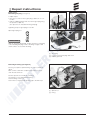
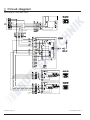
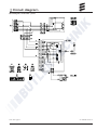
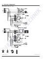
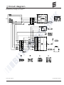
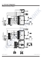
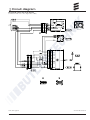
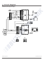
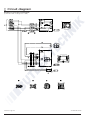
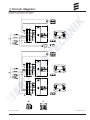
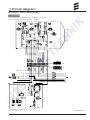
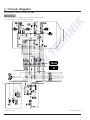
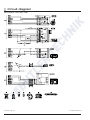
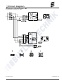
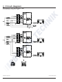
1
AIRTRONIC / AIRTRONIC M Troubleshooting and Repair Instructions Airtronic Airtronic D2, 12 V Airtronic D2, 24 V Airtronic D2 Camper, 12 V Order no. Airtronic M Order no. 25 2069 05 00 00 25 2070 05 00 00 25 2326 05 00 00 Airtronic D3, 12 V 25 2317 05 00 00 Airtronic B4, 12 V 20 1812 05 00 00 Airtronic D4, 12 V Airtronic D4, 24 V 25 2113 05 00 00 25 2114 05 00 00 Airtronic D4 Plus, 12 V Airtronic D4 Plus, 24 V 25 2484 05 00 00 25 2489 05 00 00 Airtronic D4S, 12 V Airtronic D4S, 24 V 25 2144 05 00 00 25 2145 05 00 00 25 2318 05 00 00 Complete package Airtronic D2, 12 V Airtronic D2, 24 V 25 2115 05 00 00 25 2116 05 00 00 Airtronic D3 Camper, 12 V (see Airtronic D3) Airtronic D4 Camper, 12 V Airtronic D4 Camper plus, 12 V Air heater for diesel and petrol operating independently of the engine. 25 2115 95 19 01 04.2009 25 2327 05 00 00 1 Introduction Contents This list of contents gives you precise information about the contents of the Troubleshooting and Repair Instructions. Chapter Use the index, list of abbreviations, etc, to look for a term, technical word or an explanation for an abbreviation. Title Contents Introduction • Foreword................................................................................................................... 4 • Accident prevention................................................................................................... 4 • Special text structure, presentation and picture symbols............................................ 4 • Important information before starting work................................................................. 4 Function and use Cutaway view............................................................................................................. 5 • Description of functions – Switching on........................................................................................................... 6 – Starting the Airtronic............................................................................................... 6 – Starting the Airtronic M........................................................................................... 6 – Temperature selection with the control element....................................................... 6 – Control in heating mode.......................................................................................... 6 – Ventilating mode..................................................................................................... 6 – Switching off........................................................................................................... 6 • Control and safety devices......................................................................................... 7 – Forced shut-down for ADR operation..................................................................... 7 – Emergency shutdown – EMERGENCY OFF............................................................ 7 Technical data • Airtronic (for diesel) . .................................................................................................. 8 • Airtronic M (for petrol)................................................................................................. 9 • Airtronic M (for diesel)......................................................................................... 10, 11 • Check values – Test speed for the blower...................................................................................... 12 – Resistan\ce values................................................................................................ 12 – Switching value..................................................................................................... 12 – Exhaust emission specification.............................................................................. 12 – Check “external temperature sensor”.................................................................... 12 – Table of values: “External temperature sensor”...................................................... 12 Troubleshooting • What to check first in case of faults – Check................................................................................................................... 13 – Electrical components.......................................................................................... 13 – Measure battery voltage........................................................................................ 13 – Measures voltage supply...................................................................................... 13 – Check switch-on signal......................................................................................... 13 – Check control unit................................................................................................. 13 • Overview of the individual test equipment and control units...................................... 14 • Locking the control box............................................................................................ 14 • Cancel the control box lock...................................................................................... 14 • Important notes (diagnosis of heaters with mini-controller)........................................ 14 • Testing device for the control device......................................................................... 15 • Fault diagnosis using the diagnostic unit............................................................ 15, 16 • Fault diagnosis using the EDiTH diagnostics tool with ISO adapter........................... 17 • Air pressure sensor diagnosis using EDiTH diagnostics tool and ISO adapter........... 18 • Fault diagnosis using the EDiTH diagnostics tool with basic adapter........................ 19 • Fault diagnosis using the module timer..................................................................... 20 • Fault diagnosis using the radio remote control TP5.................................................. 21 • Fault diagnosis using the EasyStart R+ radio remote control or the EasyStart T timer................................................................................................ 22 • Fault code table................................................................................................23 – 27 1 2 3 4 2 Page 1 Introduction Chapter 5 6 7 Title Contents Page Repair instructions • Repair instructions................................................................................................... 28 • Always observe the following safety instructions before working on the heater......... 28 • Special tool, AMP release tool.................................................................................. 28 • Assembly drawing Airtronic / Airtronic M.................................................................. 29 • Repair step 1, remove the heater cover.................................................................... 30 • Repair step 2, dismantle control box, check control box.......................................... 30 • Repair step 3, dismantle glow plug........................................................................... 31 • Repair step 4, renew lining....................................................................................... 31 • Repair step 5, dismantle combination sensor (overheating / flame sensor................ 32 • Repair step 6, install combination sensor (overheating / flame sensor)...................... 33 • Repair step 7, dismantle heat exchanger / dismantle combustion air fan.................................................................................... 34 • Repair step 8, dismantle combustion chamber......................................................... 35 • Check fuel supply..................................................................................................... 36 • Measuring the fuel quantity...................................................................................... 36 Circuit diagrams Overview of the parts lists and circuit diagrams........................................................... 37 • Parts list circuit diagrams Airtronic / Airtronic M........................................................ 38 • Circuit diagram Airtronic / Airtronic M...................................................................... 39 This circuit diagram is valid for heaters with one diagnosis cable and a control box cable loom wich is firmly encapsulated. • Circuit diagram Airtronic / Airtronic M...................................................................... 40 This circuit diagram is for heaters with 2 diagnostics cable and whose control box cable loom is wound with cable tape. • Parts list circuit diagrams, control units..................................................................... 41 • Circuit diagram control units – part 1........................................................................ 42 • Circuit diagram control units – part 2........................................................................ 43 • Circuit diagram control units – part 3........................................................................ 44 • Circuit diagram control units – part 4........................................................................ 45 • Circuit diagram control units – part 5........................................................................ 46 • Circuit diagram control units – part 6........................................................................ 47 • Circuit diagram control units – part 7........................................................................ 48 • Parts list circuit diagram control unit EasyStart R+ / R / T......................................... 49 • Circuit diagram control unit EasyStart R+ (control box with 1 diagnostics cable)....... 50 • Circuit diagram control unit EasyStart R+ (control box with 1 diagnostics cable)....... 51 • Circuit diagram control unit EasyStart R+ (control box with 2 diagnostics cable)....... 52 • Circuit diagram control unit EasyStart R (control box with 1 / 2 diagnostics cables).. 53 • Circuit diagram control unit EasyStart R (control box with 2 diagnostics cables)....... 54 • Circuit diagram control unit EasyStart R (control box with 1 diagnostics cables)....... 55 • Circuit diagram control unit EasyStart T (control box with 1 diagnostics cable)......... 56 • Circuit diagram control unit EasyStart T (control box with 2 diagnostics cable)......... 57 • Parts list circuit diagrams Airtronic / Airtronic M – ADR............................................. 58 • Circuit diagram Airtronic / Airtronic M – ADR........................................................... 59 1 encapsulated diagnostics cable and control box cable loom firmly encapsulated • Circuit diagram Airtronic / Airtronic M – ADR........................................................... 60 2 diagnostics cables and control box cable loom with cable tape • Parts list circuit diagrams, control units – ADR.......................................................... 61 • Parts list circuit diagrams, control units – EasyStart T – ADR.................................... 61 • Circuit diagram control units – ADR.......................................................................... 62 • Circuit diagram control unit EasyStart T – ADR (control box with 1 diag. cable)........ 63 • Circuit diagram control unit EasyStart T – ADR (control box with 2 diag. cable)........ 64 Service • Certification.............................................................................................................. 65 • Disposal................................................................................................................... 65 • EC Declaration of Conformity................................................................................... 65 • Representatives abroad.................................................................................... 66, 67 • List of key words................................................................................................ 68, 69 • List of abbreviations................................................................................................. 69 3 1 Introduction Foreword These Troubleshooting and Repair Instructions are applicable to the heaters listed on the title Page, to the exclusion of all liability claims. Depending on the version or revised status of the heater, there may be differences between it and these troubleshooting and repair instructions. The user must check this before carrying out the repair work and, if necessary, take the differences into account. Caution! Safety instructions for installation and repair! Improper installation or repair of Eberspächer heaters can cause a fire or result poisonous exhaust entering the inside of the vehicle. This can cause serious and even fatal risks. The heater may only be installed according to the specifications in the technical documents or repaired using original spare parts by authorised and trained persons. Installation and repairs by unauthorised and untrained persons, repairs using non-original spare parts and without the technical documents required for installation and repair are dangerous and therefore are not permitted. A repair may only be carried out in connection with the respective unit-related technical description, installation instructions, operating instructions and maintenance instructions. This document must be carefully read through before / during installation and repair and followed throughout. Particular attention is to be paid to the official regulations, the safety instructions and the general information. Please note! The relevant rules of sound engineering practice and any information provided by the vehicle manufacturer are to be observed during the installation and repair. Eberspächer does not accept any liability for defects and damage, which are due to installation or repair by unauthorised and untrained persons. Compliance with the official regulations and the safety instructions is prerequisite for liability claims. Failure to comply with the official regulations and safety instructions leads to exclusion of any liability of the heater manufacturer. Accident prevention General accident prevention regulations and the corresponding workshop and operating safety instructions are to be observed. 4 Special text structure, presentation and picture symbols Special text formats and picture symbols are used in these instructions to emphasise different situations and subjects. Please refer to the following examples for their meanings and appropriate action. Special text formats and presentations • A dot (•) indicates a list, which is started by a heading. – If an indented dash (–) follows a “dot”, this list is a subsection of the black dot. Picture symbols Danger! This information points out a dangerous situation for a person and / or the product. Failure to comply with these instructions can result in injuries to people and / or damage to machinery. Caution! This information points out a dangerous situation for a person and / or the product. Failure to comply with these instructions can result in injuries to people and / or damage to machinery. Important information before starting work Initial commissioning of the heater or functional test after a repair • After installing the heater, the whole fuel supply system must be carefully vented: please refer to and follow the vehicle manufacturer’s instructions. • During the heater trial run, all fuel connections must be checked for leaks and secure, tight fit. • If faults occur while the heater is running, use a diagnostic unit to determine and correct the cause of the fault. 2 Function and use Cutaway view 1 2 3 4 5 6 7 8 9 10 11 12 13 14 15 Heater impeller Control box Combustion air fan impeller Glow plug Cover Heat exchanger Combination sensor (overheating / flame sensor) Radio remote control (mobile unit) Radio remote control (stationary unit) Button Temperature sensor (room temperature) Fuse bracket with main fuse and “actuation” fuse Electrical motor Fuel connection Flange seal 16 Combustion chamber 17 Outlet hood 18 Combustion air hose 19 Metering pump 20 Pot-type strainer, installed in the dosing pump 21 Outflow 22 Flexible exhaust pipe F = Fresh air W = Hot air A= Exhaust B= Fuel V= Combustion air 5 2 Function and use Description of functions Switching on Control in the heating mode When the heater is switched on, the control lamp in the control unit lights up. The glow plug is switched on and the fan starts at low speed. During the heating mode, the room temperature or the temperature of the sucked in heating air is constantly measured. If the temperature is higher than the temperature selected on the control element, the heater starts to regulate its output. There are 4 control stages so that the outflow of heat produced by the heater can be adjusted finely to the heating requirements. Fan speed and fuel quantity correspond to the particular control stage. If the set temperature is still exceeded in the smallest control stage, the heater goes to the “OFF” stage with the fan running on for approx. 4 minutes to cool off. The fan then continues running at minimum speed (circulation mode) until the restart or is switched off (fresh air mode with external temperature sensor). Please note! f there is still too much residual heat in the heat exchanger from when the heater was last used, firstly only the fan starts up (cold blowing). Once the residual heat has been cleared, the heater starts. Starting Airtronic After approx. 65 seconds the fuel supply starts and the fuel / air mixture in the combustion chamber ignites. Once the combined sensor (flame sensor) has detected the flame, the glow plug is switched off after 60 seconds. The heater is now in standard operation. Starting Airtronic M After approx. 60 seconds the fuel supply starts and the fuel / air mixture in the combustion chamber ignites. After the flame sensor has detected the flame, the glow plug is switched off after approx. 90 sec. The heater is now in standard operation. After another 120 seconds, the heater has reached the “POWER” stage (maximum fuel quantity, maximum fan speed). Temperature selection with the control element The control can be used to preselect an interior temperature. The resulting temperature can be within the range of +10 °C to +30 °C and depends on the selected heater, on the size of the space to be heated and on the prevailing outdoor temperature. The setting to be selected at the control is an empirical value. 6 Ventilating mode The EasyStart R+ and EasyStart T control units and the minicontroller can be used to activate the „Ventilate“ function. The „Heat / Ventilate“ switch is also required for the modular timer and control device whereby, for fan mode, the „Heat / Ventilate“ switch must be pressed first and then the heater switched on. The blower runs at maximum speed in fan mode. Switching off When the heater is switched off, the control lamp goes off and the fuel supply is switched off. The fan runs on for approx. 4 minutes to cool down. While the fan is running on, the glow plug is switched on for approx. 40 seconds to clean. Special case: If no fuel has been supplied or if the heater is in the “OFF” stage until it is switched off, the heater is stopped without any after running. 2 Function and use Control and safety devices • If the heater does not ignite within 90 seconds after starting the fuel pump, the start is repeated. If the heater still does not ignite after another 90 seconds of pumping fuel, the heater is switched off, i.e. the fuel supply is off and the fan runs on for approx. 4 minutes. • If the flame goes off by itself during operation, the heater is restarted. If the heater does not ignite within 90 seconds after the fuel pump has started, or ignites and goes off again within 15 minutes, the heater is switched off, i.e. the fuel supply is off and the fan runs on for approx. 4 minutes. This status can be remedied by briefly switching off and on again. Do not repeat the switching off / on routine more than twice. • In the case of overheating, the combined sensor (flame sensor / overheating sensor) triggers, the fuel supply is interrupted and the heater switched off. Once the cause of the overheating has been eliminated, the heater can be restarted by switching off and on again. • If the lower or upper voltage limit is reached, the heater is switched off after 20 seconds. Forced shut-down for ADR operation In vehicles for the transport of dangerous goods (e.g. tanker trucks), the heater must be switched off before the truck drives into a danger area (refinery, petrol station, etc.). Failure to comply results in the heater automatically switching off if: • the vehicle engine is switched off, • an additional unit is started up (auxiliary drive for unloading pump, etc.), • a vehicle door is opened (ADR99 regulation, only in France). The fan then runs on for max. 40 seconds. Emergency shutdown – EMERGENCY OFF If an emergency shutdown –EMERGENCY OFF – is required during operation, execute the following: • Switch the heater off at the control element or • remove the fuse or • disconnect the heater from the battery. • The heater does not start up if the glow plug or blower motor is defective or if the electric lead to the metering pump is interrupted. • If the combined sensor (flame sensor / overheating sensor) is defect or the electric lead interrupted, the heater starts up and is then switched off again during the start phase. • The speed of the fan motor is monitored continuously. If the fan motor does not start up or if the speed deviates by more than 10%, the heater is switched off after 30 sec. • When the heater is switched off, the glow plug is switched on for 40 seconds (after-glowing) while the fan runs on to clean off any combustion residues. Please note! Do not repeat the switching off / on routine more than twice. 7 3 Technichal data Technichal data Airtronic Heater type Heater Airtronic D2 / Airtronic D2 Camper Version D2 / D2 Camper Air Heating medium Stage Control of the heat flow Power Large Medium Small Off 2200 1800 1200 850 – Heater air flow rate without counterpressure (kg/h) with hood Ø 60 mm 105 90 60 40 13 Fuel consumption (l/h) 0.28 0.23 0.15 0.10 – Elektr. power consumption (watt) in operation (12 and 24 volt) 34 22 12 8 5 Heat flow (watt) at start (12 and 24 volt) #100 Rated voltage 12 or 24 volt Operating range Lower voltage limit: An undervoltage protection in the controller switches off the heater when the voltage limit is reached. approx. 10.5 volt resp. 21 volt Undervoltage protection trigger time: 20 seconds Upper voltage limit: An uppervoltage protection in the controller switches off the heater when the voltage limit is reached. approx. 16 volt resp. 32 volt Overvoltage protection trigger time: 20 seconds Fuel Diesel DIN EN 590 (commercially available) Tolarable ambient temperature in operation no operation Heater –40 °C to +70 °C –40 °C to +85 °C Dosing pump –40 °C to +50 °C –40 °C to +125 °C Maximum air intake temperature Interference suppression max. +40 °C Interference suppression class 5 to DIN EN 55 025 Weight approx. 2.7 kg Ventilation mode possible Please note! Caution! Safety instructions for technical data! Failure to comply with the technical data can result in malfunctions. 8 Provided no limit values are given, the technical data listed is subject to the tolerances usually applicable to heaters of ±10% for nominal voltage, ambient temperature 20 °C and reference altitude Esslingen. 3 Technichal data Technichal data Heater type Airtronic M Heater Airtronic B4 Version B4 Heating medium Air Stage Control of the heat flow Power Large Medium Small Off 3800 3200 2100 1300 – Heater air flow rate without counterpressure (kg/h) with hood Ø 90 mm 185 160 120 85 24 Fuel consumption (l/h) 0.54 0.46 0.29 0.18 – Elektr. power consumption (watt) in operation (12 and 24 volt) 40 29 15 9 5 Heat flow (watt) at start (12 and 24 volt) #100 Rated voltage 12 volt Operating range Lower voltage limit: An undervoltage protection in the controller switches off the heater when the voltage limit is reached. approx. 10.5 volt Undervoltage protection trigger time: 20 seconds Upper voltage limit: An uppervoltage protection in the controller switches off the heater when the voltage limit is reached. 16 volt Overvoltage protection trigger time: 20 seconds Fuel Petrol DIN EN 228 (commercially available) Tolarable ambient temperature in operation no operation Heater –40 °C to +50 °C –40 °C to +85 °C Dosing pump –40 °C to +20 °C –40 °C to +125 °C Maximum air intake temperature Interference suppression max. +40 °C Interference suppression class 5 to DIN EN 55 025 Weight ca. 4.5 kg Ventilation mode possible Please note! Caution! Safety instructions for technical data! Failure to comply with the technical data can result in malfunctions. Provided no limit values are given, the technical data listed is subject to the tolerances usually applicable to heaters of ±10% for nominal voltage, ambient temperature 20 °C and reference altitude Esslingen. 9 3 Technichal data Technichal data Airtronic M Heater type Heater Airtronic D3 / Airtronic D4 / Airtronic D4 Plus Version D3 / D4 / D4 Plus Air Heating medium Stage Control of the heat flow Power Large Medium Small Off Heat flow (watt) D3 3000 2200 1600 900 – D4 4000 3000 2000 900 – D4 Plus 4000 3000 2000 900 – Heater air flow rate without counterpressure (kg/h) D3 with hood Ø 90 mm 150 120 90 60 24 D4 with hood Ø 90 mm 185 150 110 60 24 D4 Plus with hood Ø 75 mm 175 140 100 55 22 Fuel consumption (l/h) D3 0.38 0.28 0.2 0.11 – D4 0.51 0.38 0.25 0.11 – D4 Plus 0.51 0.38 0.25 0.11 – Elektr. power consumption (watt) D3 24 16 10 7 5 in operation (12 and 24 volt) D4 40 24 13 7 5 D4 Plus 55 30 16 7 5 at start (12 and 24 volt) #100 Rated voltage 12 or 24 volt Operating range Lower voltage limit: An undervoltage protection in the controller switches off the heater when the voltage limit is reached. approx. 10.5 volt resp. 21 volt Undervoltage protection trigger time: 20 seconds Upper voltage limit: An uppervoltage protection in the controller switches off the heater when the voltage limit is reached. approx. 16 volt resp. 32 volt Overvoltage protection trigger time: 20 seconds Fuel Diesel DIN EN 590 (commercially available) Tolarable ambient temperature in operation no operation Heater –40 °C to +70 °C –40 °C to +85 °C Dosing pump –40 °C to +50 °C –40 °C to +125 °C Maximum air intake temperature Interference suppression max. +40 °C Interference suppression class 5 to DIN EN 55 025 Weight approx. 4.5 kg Ventilation mode possible Please note! Caution! Safety instructions for technical data! Failure to comply with the technical data can result in malfunctions. 10 Provided no limit values are given, the technical data listed is subject to the tolerances usually applicable to heaters of ±10% for nominal voltage, ambient temperature 20 °C and reference altitude Esslingen. 3 Technichal data Technichal data Airtronic M Heater type Heater Airtronic D4S / Airtronic D4 Camper / Airtronic D4 Camper Plus Version D4S / D4 Camper / D4 Camper Plus Air Heating medium Control of the heat flow Stage Heat flow (watt) Large Medium Small Off D4S 3500 3000 2000 1000 – 3000 2000 900 – 140 100 60 22 150 / 140 110 / 100 60 / 55 24 / 22 0.38 0.25 0.13 – 0.38 0.25 0.11 – D4S 160 D4 Camper / D4 Camper Plus 185 / 160 Fuel consumption (l/h)) Power D4 Camper / D4 Camper Plus 4000 / 3500 Heater air flow rate without counterpressure (kg/h) D4S 0.44 D4 Camper / D4 Camper Plus 0.51 / 0.44 Elektr. power consumption (watt) D4S 40 30 16 8 5 in operation (12 and 24 v) D4 Camper / D4 Camper Plus 40 24 / 30 13 / 16 7 / 8 5 at start (12 and 24 v) #100 Rated voltage 12 or 24 volt Operating range Lower voltage limit: An undervoltage protection in the controller switches off the heater when the voltage limit is reached. approx. 10.5 volt resp. 21 volt Undervoltage protection trigger time: 20 seconds Upper voltage limit: An uppervoltage protection in the controller switches off the heater when the voltage limit is reached. approx. 16 volt resp. 32 volt Overvoltage protection trigger time: 20 seconds Fuel Diesel DIN EN 590 (commercially available) Tolarable ambient temperature in operation no operation Heater –40 °C to +70 °C –40 °C to +85 °C Dosing pump –40 °C to +50 °C –40 °C to +125 °C Maximum air intake temperature Interference suppression max. +40 °C Interference suppression class 5 to DIN EN 55 025 Weight approx. 4.5 kg Ventilation mode possible Please note! Caution! Safety instructions for technical data! Failure to comply with the technical data can result in malfunctions. Provided no limit values are given, the technical data listed is subject to the tolerances usually applicable to heaters of ±10% for nominal voltage, ambient temperature 20 °C and reference altitude Esslingen. 11 3 Technical data Check values Test speed for the blower Airtronic D2 / D2 Camper (12 volt / 24 volt) • 12 volt 5000 rpm ±25 % at U = 10,0 volt • 24 volt 5000 rpm ±25 % at U = 18,0 volt Airtronic B4 (12 volt) Airtronic D3 / D3 Camper (12 volt) Airtronic D4 (12 volt / 24 volt) Airtronic D4 Camper (12 volt) • 12 volt 4400 rpm ±25 % • 24 volt 4400 rpm ±25 % at U = 10,0 volt at U = 18,5 volt Airtronic D4S / Airtronic D4 Plus (12 volt / 24 volt) Airtronic D4 Camper Plus (12 volt) • 12 volt 4400 rpm ±25 % at U = 10,5 volt • 24 volt 4400 rpm ±25 % at U = 19,0 volt Resistance values at 20 °C Glow plug Dosing pump Control unit resistance values Control device 12 volt / 24 volt Modular timer and mini-controller 12 volt / 24 volt 12 volt 24 volt 0.42 – 0.70 9.5 ±0.50 1.2 – 2.0 36.0 ±1.8 Switch position, Switch position, left limit stop right limit stop min. 1720 min. 2096 max. 1760 max. 2216 min. 1730 max. 1780 min. 2120 max. 2240 Switching value Overheating sensor 140 °C – 170 °C measured in the “High” control stage and at a distance of 300 mm downstream from the hot air outlet Exhaust emission specification CO2 in exhaust in control stage “high” 7,5 – 12,5 Vol. % Smoke spot number according to Bacharach <4 Check “external” temperature sensor (Order No.: 25 1774 89 03 00) The “external” temperature sensor test must be carried out using a digital multimeter. If the resistance value is not the same as the curve in the diagram or the table of values, replace the temperature sensor. 2400 Resistance (ohm) 2200 2000 1800 1600 1400 1200 1000 ±40 12 ±30 ±20 ±10 0 10 20 Temperature (°C) 30 40 50 Table of values – “external” temperature sensor Temperature °C 0 5 10 15 20 25 30 35 40 45 Resistance min. 1600 1670 1745 1820 1895 1970 2050 2130 2210 2295 max. 1660 1730 1800 1870 1950 2030 2110 2190 2280 2370 4 Troubleshooting What to check first in case of faults • Check – Fuel in the tank? – Fuel pipes leaking? (visual check) – Summer diesel in the fuel pipe? – Combustion air system or exhaust system damaged or blocked? – Hot air system blocked? – Air pressure sensor installed? If yes, refer to „What to do if…?“ chapter of the „Altitude Kit“ installation instructions. – New generation control box installed? Features: >Cable loom of control box wound with cable tie >Temperature sensor mounted on the side of the control box (visible when cover removed) • Electrical components – Cables, connections damaged? – Contacts corroded? – Fuses defective? – Incorrect wiring? (short circuits, interrupted / broken) • Measure battery voltage – Battery voltage < 10.5 volt, the undervoltage protection of the 12 volt heater has triggered. – Battery voltage < 21 volt, the un • Measure voltage supply (Cl 30) Disconnect the 16-pin connector S1 / B1 and measure the voltage applied at connector B1 between chamber 1 (cable 2.52 rt) and chamber 10 (cable 2.52 br). If it differs from the battery voltage, check the fuses, the supply cables, the negative connection and the positive support point on the battery for voltage drop (corrosion / interruption). • Check switch-on signal Disconnect the 16-pin connector S1 / B1 and then switch on the heater at the control unit. Check whether voltage is applied in the connector B1 between chamber 4 (cable 0.52 ge) and chamber 10 (cable 2.52 br). If no voltage is measured, then check the supply cable (cable 0.52 ge), the 5 A fuse (item 2.7.1 in the circuit diagram) and the control unit. • Check control unit Control device, mini-timer, mini-controller and modular timer Disconnect the connector at the control unit; install a jumper between the red 0.5² rt cable and the yellow 0.5² ge cable. If a voltage is measured in connector B1 between chamber 4 (cable 0.5² ge) and chamber 10 (cable 2.5² br), then replace the control unit. EasyStart R+ / EasyStart R / EasyStart T Disconnect the connector at the control unit; install a jumper between the black/white 0.5² bl/ws cable and the red 0.5²rt cable. If a voltage is measured in connector B1 between chamber 8 (cable 0.5² bl/ws) and chamber 10 (cable 2.5² br), then replace the control unit. 13 4 Troubleshooting Overview of the test equipment and control units suitable for diagnosis Important notes on diagnosis of heaters with mini-controller control unit The electronic control box can store up to 5 faults, which can be read out and displayed. The following test equipment and/ or control units can be used to query the fault memory in the control box and if necessary to delete the locking of the control box: Caution! When checking the heater with the diagnostics unit or the EDiTH diagnostics tool the order given in the following notes must always be followed as otherwise the heater detects Error 62 (control unit – interruption) and switches to emergency operation. Test equipment • Testing device for the control device • Diagnostic unit additionally required: Adapter cable • EDiTH diagnostic tool – Basic adapter with software additionally required: Airtronic extension – ISO-adapter additionally required: Adapter cable Order No.: Mini-controller in stand-alone operation 22 1509 89 00 00 22 1529 89 00 00 22 1000 31 86 00 22 1542 89 00 00 22 1537 89 00 00 22 1541 89 00 00 22 1000 31 86 00 – „Air pressure sensor“ adapter cable22 1000 33 31 00 Only for heaters with connected air pressure sensor for reading out the „air pressure sensor“ fault memory. If a diagnostics cable is connected, the following control units can also be used: Control units Order No.: • Module timer 22 1000 30 34 00 • TP5 radio remote control 22 1000 32 01 00 • EasyStart T 22 1000 32 88 00 • EasyStart R+ 22 1000 32 80 00 Please note! If the fault memory cannot be read out, check the diagnostics cable for correct laying and possible damage. • Connect adapter cable 22 1000 31 86 00 as described in the operating instruction. • Select operating mode (Heat / Ventilate) at the mini-controller • Perform diagnosis using the diagnostics unit or the EDiTH diagnostics tool. • Switch off the mini-controller after finishing the diagnosis • Remove the adapter cable Mini-controller in combination with mini-timer • Connect adapter cable 22 1000 31 86 00 as described in the operating instruction. • Press the m button of the mini-timer • Select operating mode (see mini-timer operating instructions) • Perform diagnosis using the diagnostics unit or the EDiTH diagnostics tool. • Switch off the mini-timer after finishing the diagnosis • Remove the adapter cable Mini-controller in combination with TP5 • Connect adapter cable 22 1000 31 86 00 as described in the operating instruction. • Press the button of the TP5 radio remote control • Select operating mode (see TP5 radio remote control operating instruction) • Perform diagnosis. • Switch off TP5 radio remote control after finishing the diagnosis • Remove the adapter cable Please note! If the operating mode is to be changed during the test the heater must be switched off first using the diagnostics unit or the EDiTH diagnostics tool, otherwise the heater detects Error 62 (control unit – interruption) and switches to emergency operation. Test mini controller The mini-controller must be connected to the heater for testing. The setpoint value can be displayed using the EDiTH diagnostics tool. If the rotary knob is at the left limit stop the setpoint value is 8 °C, at the right limit stop it is 34 °C. Please note! The resistance of the setpoint value potentiometer cannot be measured directly. The measured values are not meaningful. 14 4 Troubleshooting Testing device for the control device (Order No.: 22 1509 89 00 00) Prepare for test Connect the correct operating voltage (12 or 24 volt) to the testing device, with plus at the red connector socket and minus at the blue connector socket. • Disconnect socket from the control unit. • Connect cable loom from testing device with the control unit. • Set the rotary knob of the control unit to “Heat”, the corresponding red LED in the testing device must light up. • Set control unit to “0”, then press the “LED – red” button, the red control lamp in the control unit must light up. • Set control unit to “Heat”, then press the “LED – green” button, corresponding red control lamp in the testing device and the green control lamp in the control unit must light up. Caution! Safety instructions for checking the control unit! Ensure you use the correct operating voltage, otherwise the connected components can be severely damaged. Check the setpoint potentiometer of the control unit Set the “Temperature sensor / Potentiometer” switch in the testing device to the “Potentiometer” setting and slowly turn the rotary knob of the control unit. The green LED – temperature sensor / potentiometer must light up continuously. In case of a fault, replace the control unit. 1 2 Testing device Control device Diagnostic unit (Order No.: 22 1529 89 00 00) An additional adapter cable is required to connect the diagnostic unit (Order No.: 22 1000 31 86 00). The current fault is displayed as “AF” and a 2-digit number and is always written in the memory position F1. Preceding faults are moved to the memory locations F2 – F5, if necessary the contents of memory position F5 is overwritten. Please note! • Not only the defective component, but also a defective current circuit results in a fault being displayed. • In heaters with connected air pressure sensor the diagnostics unit can be used to read out the fault memory of the heater only. The fault memory of the „air pressure sensor“ can be read out using the EDiTH diagnostics tool only. • Fault code, fault description, cause / remedial action are described on Pages 23 – 27. l –Delete fault memory l –Delete fault memory d –Switch heater on / off, request diagnosis e –Reverse, F5 – F1 f –Forward, F1 – F5, current fault (AF) Connect diagnostics unit, see page 16. 15 4 Troubleshooting Connect diagnostic unit • Disconnect the 8-pin connector of the heater’s cable harness and connect the adapter cable. • Connect the diagnostic unit to the adapter cable. Display is as follows: Display of the fault memory F1 – F5 or F5 – F1 • Press the e or f button, or press several times, to display the fault memory. Display is as follows: Delete fault memory • Press both L buttons simultaneously until the following appears in the display: Display is as follows: or Heater has no malfunction e.g. current error / fault code 64 or • If the fault memory has been deleted the most recent current fault is displayed. The current fault is not reset to 00 until the heater is restarted – provided there is no new, more recent fault. Display is as follows: e.g. fault memory 2 / fault code 10 Only the fault memory positions with an error assigned to them are displayed. • After 8 sec the following is displayed: Display is as follows: Please note! Query fault memory • Use the D key to switch on the heater. Display is as follows: Fault diagnosis not possible Possible causes: – Adapter cable is not properly connected. – Control box is defective or is not capable of diagnosing (not a universal control box). Heater has no malfunction Cancel the control box lock • Delete the fault memory as described and switch off the heater using the d key. • The control box lock is cancelled and the diagnosis closed. Display is as follows: 1 2 3 1 2 3 16 Heater Adapter cable Diagnostic unit 4 Troubleshooting EDiTH diagnostic tool with ISO adapter (Order No.: 22 1541 89 00 00) An additional adapter cable is required to connect the ISO adapter (Order No.: 22 1000 31 86 00). Please note! • It is very important to always install in the given order. • Not only the defective component, but also a defective current circuit results in a fault being displayed. • Fault code, fault description, cause / remedial action are described on Pages 23 – 27. • The EDiTH diagnostics tool scope of supply does not include the software; this must be downloaded from the Service Portal. Query / delete fault memory F1 – F5 or cancel the control box lock • Start the software on your PC: – on the desktop —> double click the “EDiTH” icon – Select heater type – Press the “GO” button. • Delete fault memory or cancel the control box lock: – press the “Delete fault memory” button —> the stored faults F1 – F5 are deleted and the control box is unlocked. Quit diagnosis • Press the “STOP” button —> fault memory query is ended. Connect ISO adapter • Disconnect the heater’s cable harness. • Connect the adapter cable to the cable harness – as shown in the sketch. • Connect the adapter cable to the ISO adapter. • Connect the SUB-D connection cable with the PC and the ISO adapter. Installing the software on your PC • Double click the “setup.exe” file to start the installation and following the SETUP program instructions. 1 2 3 Heater Adapter cable ISO adapter 4 5 e SUB-D connection cable USB to Serial RS-232 adapter 17 4 Troubleshooting Air pressure sensor diagnosis using EDiTH diagnostics tool and ISO adapter (Order No. 22 1524 89 00 00) An additional adapter cable is required to connect the ISO adapter (Order No.: 22 1000 33 31 00). The air pressure sensor connected to the heater can be diagnosed. If faults occur during the altitude adjustment they are stored in the air pressure sensor. If necessary, faults can be read out using the ISO adapter in conjunction with the EDiTH diagnostics tool – from Version S3V7-F – and the additionally necessary adapter cable. Please note! • It is very important to always install in the given order. • Not only the defective component, but also a defective current circuit results in a fault being displayed. • Fault code, fault description, cause / remedial action are described on pages 27. • The EDiTH diagnostics tool scope of supply does not include the software; this must be downloaded from the Service Portal. 1 2 3 4 18 Air pressure sensor Adapter cable Cable loom from heater Cable loom to control unit Perform diagnosis of the air pressure sensor Disconnect the connector between the air pressure sensor / heater, control unit, connect the ISO adapter with the adapter cable (see sketch). Start the diagnosis of the air pressure sensor. • Double-click the >>EDiTH<< icon on the desktop. • Select the air pressure sensor in the »Heater and Test Selection«. The following actions are possible: – Read out the current fault and the fault memory. – Delete the fault memory. – Query the current measured air pressure. – Query the operating state. – Query the general data. – Print out the fault memory and / or the general data • Exit the diagnosis with the »Stop« button or by closing all windows. – Selection: Save analysis / Do not save analysis • Remove ISO adapter and adapter cable from the lead harness and reconnect the air pressure sensor / heater, control unit connector. 5 6 7 ISO adapter SUB-D connection cable USB to Serial RS-232 adapter 4 Troubleshooting EDiTH diagnostic tool with basic adapter EDiTH basic adapter (Order No.: 22 1542 89 00 00) An additional extension is required to check the control box (Order No.: 22 1537 89 00 00). Please note! • It is important to always follow the precise connection order as given below! • The Hall sensor integrated in the control box can only be properly tested in the control box is correctly placed on the extension. • Only push or pull on the connectors, not on the cables! • Only use the network cable and RS232 cable with snap ferrites included in the scope of supply. Use original accessories with snap ferrites only to connect the test equipment. • Not only the defective component, but also a defective current circuit results in a fault being displayed. • Fault code, fault description, cause / remedial action are described on Pages 23 – 27. (A) (B) (C) (D) (E) (F) (G) Basic adapter SUB-D connection cable Mains connection Mains switch USB to Serial RS-232 adapter Adapter Control box Caution! Magnetic field! During the test operation a magnetic field develops at the adapter. Therefore, do not place any objects such as data media, credit cards, etc. on the adapter or in its immediate vicinity. Connect basic adapter • Start computer and wait until the system has successfully booted. • Start PC software. • Insert the unit connector of the mains cable in the basic adapter (A) and connect the mains connection (C) to the mains. • Connect the SUB-D connection cable (B) with the PC and basic adapter (A). Connect extension and test control box • Connect the extension to the basic adapter (A). • Connect the control box (E) to the extension and the adapter (F). • Switch on the basic adapter (A) at the mains switch (D). • Select the control box version and operating voltage (12 V / 24 V) in the PC software. • Start the control box test with the PC software. A more detailed description of how to operate the basic adapters (A) is given in the EDiTH online help. Cable colours sw = black gn = green bl = blue 19 4 Troubleshooting Module timer (Order No.: 22 1000 30 34 00) The current fault is displayed as “AF” and is always written in memory position F1. Preceding faults are moved to the memory locations F2 – F5, if necessary the contents of memory position F5 is overwritten. Please note! • Not only the defective component, but also a defective current circuit results in a fault being displayed. • In heaters with connected air pressure sensor the modular timer cannot be used to perform diagnoses. The diagnostics unit or the EDiTH diagnostics tool must be used to perform the diagnosis. The fault memory of the „air pressure sensor“ can be read out using the EDiTH diagnostics tool only. • Fault code, fault description, cause / remedial action are described on Pages 23 – 27. Query fault memory F1 – F5 Condition: The heater is switched off. • Press c key –> the heater is switched on. a –Time p –Preset c –Heat e –Reverse f –Forward Cancel the control box lock and simultaneously delete the fault memory Condition: An electrical connection exists from terminal 15 (ignition) to the module timer, 12-pin connector, chamber 10. • Press a key and keep pressed, then press p key within 2 seconds. Display is as follows: AF = current fault 3 digit number = fault code c flashes. • Press c key Display is as follows: the current fault F15 or F50. • Press f key once or several times, fault memory positions F1 – F5 are displayed. The module timer is now in the “Query fault memory” program. • Press button a, keep it depressed and then press button p within 2 seconds. • Switch off ignition (terminal 15). • Simultaneously press button a and button p, in addition, switch on the ignition (terminal 15) and wait until the following appears in the display. After ignition “ON” the following appears in the display: Display flashes, Heater symbol does not flash • Switch the heater off and on –> the control box is unlocked, the heater restarts. After switching the heater off and on and renewed query of the fault memory, the following appears in the display: 20 Display flashes, Heater symbol does not flash 4 Troubleshooting TP5 radio remote control (Order No: 22 1000 32 01 00) If faults occur while the heater is running, they are displayed with “Err” after the mobile unit is activated. After the diagnostics cable (bl/ws) has been connected and the first logs have arrived at the stationary unit, the diagnose can be carried out using the mobile unit of the TP5 radio remote control. The current fault “F0” is displayed. The stored faults “F1” to “F5” can be queried. Please note! • In order to carry out the diagnosis, the diagnostics cable (bl/ws) must be connected to the stationary unit and the heater cable harness. To this end, please refer to and follow the circuit diagram for the TP5 radio remote control and the heater. • If the diagnostics cable (bl/ws) is not connected, the “Diagnosis” menu is blocked. • Not only the defective component, but also a defective current circuit results in a fault being displayed. • In heaters with connected air pressure sensor the TP5 radio remote control cannot be used to perform diagnoses. The diagnostics unit or the EDiTH diagnostics tool must be used to perform the diagnosis. The fault memory of the „air pressure sensor“ can be read out using the EDiTH diagnostics tool only. • Fault code, fault description, cause / remedial action are described on Pages 23 – 27. Enquire / delete fault memory Use the key to activate the mobile unit. Switch on the heater with the key. Press the key twice to open the Time setting menu – the time flashes in the display. Button to activate / deactivate the mobile unit Button for forward time setting Button for backward time setting Button for activating the possible settings Button for switching heat / ventilate ON / OFF; Activate / deactivate preselected time Malfunction in heater: Use the and tions 1 to 5. Heater has no malfunction: buttons to call up the fault memory posi- Press the key for approx 2 sec – until the following appears in the display: Delete fault memory / Cancel the control box lock Use the key to delete the fault memory. Press Press Press Press key. key. key twice. key. To confirm, press the key for approx 2 sec until up in the display – fault memory is deleted. lights 21 4 Troubleshooting EasyStart R+ radio remote control (Order-No.: 22 1000 32 80 00) EasyStart T timer (Order-No.: 22 1000 32 88 00) If faults occur while the heater is running, they are displayed with “Err” after the mobile unit or timer is activated. The current fault is displayed. The stored faults “F1” to “F5” can be queried. Please note! • In order to carry out the diagnosis, the diagnostics cable (bl/ ge at heater connector, bl/ws at cable harness connector) must be connected to the stationary unit and the heater cable harness. To this end, please refer to and follow the circuit diagram for the radio remote control and the heater. • If the diagnostics cable is not connected, the “Diagnosis” menu is blocked. • Not only the defective component, but also a defective current circuit results in a fault being displayed. • The heater diagnosis can also be performed if the air pressure sensor is connected. The fault memory of the „air pressure sensor“ can be read out using the EDiTH diagnostics tool only. • Fault code, fault description, cause / remedial action are described on Pages 23 – 27. Enquire / delete fault memory Activate mobile part / timer (see EasyStart R+ / EasyStart T operating instructions) Confirm symbol with . Back control key Next control key ON / OFF activation key mobile unit / timer OK key (symbol selection / confirm input) The following actions are possible • Call up fault memory. Call up the fault memory positions F1 – F5 with • Call up fault memory again. Briefly press and simultaneously. Heater is switched on. Confirm operating time with . • Delete fault memory (display dEL) Press . Press again. The diagnosis is completed. Switch off heater. Briefly press 22 and simultaneously. or . 4 Troubleshooting Fault code Fault description Display Comments • Remedial action 000 No faults —— 004 Warning: Short circuit in control box, fresh air output • Disconnect connector S1 / B1 at the heater and at the connector B1, PIN 16 check the cable up to the fresh air fan relay for short circuit to negative, if ok —> replace control box. 005 Warning: Short circuit in control box, car alarm output • Disconnect connector S1 / B1 at the heater and at the connector B1, PIN 15 check the cable up to the relay isolating switch or burglar alarm system input for short circuit to negative, if ok —> replace control box. 006 Warning: Control box has not received any explicable altitude information. Inexplicable atmospheric altitude • Read out fault memory in the air pressure sensor using the EDiTH diagnosinformation tics tool and correct fault. (Display only if heaters labelled “H-Kit” on the nameplate.) 009 Cut-off ADR ADR shutdown due to signal change from (+) to (–) at connector S1, PIN 13 (D+) or plus signal at connector S1, PIN 14 (HA+). 010 Overvoltage – cut-off Overvoltage applied to control box for at least 20 seconds without interruption – heater not working. • Disconnect connector S1 / B1 at the heater, start the vehicle’s engine, measure the voltage at connector B1 between PIN 1 (cable 2.52 rt) and PIN 10 (cable 2.52 br). Airtronic 12 volt – voltage >16 volt —> check generator regulator Airtronic 24 volt – voltage >32 volt —> check generator regulator 011 Undervoltage – cut-off Undervoltage applied to control box for at least 20 seconds without interruption – heater not working. • Disconnect connector S1 / B1 at the heater, the vehicle’s engine is switched off, measure the voltage at connector B1 between PIN 1 (cable 2.52 rt) and PIN 10 (cable 2.52 br). The measured value and the voltage at the battery should be the same. In case of a voltage drop, check the fuses, the supply cables, the negative connections and the positive support point on the battery for corrosion and correct contact. 012 Overheating at the overheating sensor Temperature of the overheating sensor too high. • Check hot air pipes for blockage —> remove blockage. • Sum of the component ratings of air-conducting parts is too large —> Check air system, if necessary re-lay – for component ratings, please refer to additional parts catalogue. • Check overheating sensor, for diagram and table of values please refer to Page 32, if ok —> measure fuel quantity, see Page 36. 013 Overheating at the flame sensor Flame sensor signals temperature at heat exchanger is too high. • Check hot air pipes for blockage —> remove blockage. • Sum of the component ratings of air-conducting parts is too large —> Check air system, if necessary re-lay – for component ratings, please refer to additional parts catalogue. • Check flame sensor, if ok —> check overheating sensor, if overheating sensor defective —> replace combination sensor, if overheating sensor ok —> measure fuel quantity, see Page 36, for diagram and table of values for flame sensor and overheating sensor please refer to Page 32. 014 Temperature difference between flame sensor and overheating sensor too large Temperature difference between flame sensor and overheating sensor too large • Check hot air pipes for blockage —> remove blockage. • Sum of the component ratings of air-conducting parts is too large —> Check air system, if necessary re-lay – for component ratings, please refer to additional parts catalogue. • Check flame sensor, if ok —> check overheating sensor, if overheating sensor defective —> replace combination sensor, if overheating sensor ok —> measure fuel quantity, see Page 36, if fuel quantity ok — > replace control box. For diagram and table of values for flame sensor and overheating sensor, see Page 32. 23 4 Troubleshooting Fault code Fault description Display Comments • Remedial action 015 Operating lock-out The fault code 015 is displayed, if the heater was switched back on after the fault code display 017. The hardware threshold value for the overheating sensor has been exceeded —> the control box is locked. • Replace control box. 017 Overheating The hardware threshold value for the overheating sensor has been exceeded, because the control box failed to recognise the fault code 012 or 013 –> the control box is locked. If the heater is switched on again, the fault code 015 is displayed. • Replace control box. 018 • Check glow plug (see fault code 020 and 021), if ok Starting energy of the glow plug is • Check glow plug cable harness for correct laying and damage, if ok —> too low check cable harness for continuity, if ok —> replace control box. (Display only if heaters labelled “H-Kit” on the nameplate.) 019 Ignition energy too low • Check glow plug (see fault code 020 and 021), if ok • Check glow plug cable harness for correct laying and damage, if ok —> check cable harness for continuity, if ok —> replace control box. 020 Glow plug – interruption • Check glow plug for function and continuity at ambient temperature 20 °C. 12 volt heater – 0.42 up to ± 0.7 24 volt heater – 1.2 up to ± 2.0 021 Glow plug – short circuit, overload or short circuit after negative • If the values are ok —> check glow plug lead harness for damage and continuity, if ok —> replace control box. 022 * Glow plug, output (+) – short circuit after UB (battery voltage) • Check glow plug lead harness for correct laying and damage, if ok —> check lead harness for continuity, if ok —> replace control box. 025 * Diagnostics cable bl/ws – short circuit Fault code display is not possible. This fault code cannot be read out from the – after UB (battery voltage) fault memory until the fault has been corrected. • Check diagnostics cable for correct laying and possible damage. 031 Blower – interruption • Check that the lead harness of the blower motor has been correctly laid and check for damage, if ok —> remove lead harness at control box and check for continuity, if ok —> replace control box. 032 Blower motor – short circuit after negative • Carry out functional test on the blower motor, to do this remove the connector from the control box. Apply a test voltage (see page 12) to the blower motor and measure the current intensity after 40 sec. Current intensity < 6.5 A – blower motor ok –> replace control box. Current intensity > 6.5 A —> replace blower. • Check wiring for short circuit. Please note! Ensure compliance with the test voltage (see page 12). The component is destroyed if the voltage value is exceeded. Ensure the power pack has adequate short-circuit resistance – min 20 A. 033 Blower motor won’t rotate or short circuit after negative Please note! Ensure compliance with the test voltage (see page 12). The component is destroyed if the voltage value is exceeded. Ensure the power pack has adequate short-circuit resistance – min 20 A. Speed deviation > 10 % from setpoint value for longer than 30 seconds. Use a non-contact r.p.m. counter to measure the speed of the combustion air fan (see page 12 for test speed and test voltage). • Speed too low: Blower blocks – check blower for free running, if necessary remove foreign body, if ok —> check blower (see fault code 032). • Speed too high: – Magnet missing from blower impeller —> replace blower. – Speed sensor in control box is defective —> replace control box. • Check wiring for short circuit. * This fault code or ohmic value is valid for a new generation control box only. This differs from the control box to date by its cable loom wrapped in cable tape and by a temperature sensor mounted on the side, which becomes visible when the cover is removed. 24 4 Troubleshooting Fault code Fault description Display Comments • Remedial action 034 * Blower motor, outlet (+) short circuit after UB (battery voltage) • Check that the lead harness of the blower motor has been correctly laid and check for damage, if ok —> remove lead harness at control box and check for continuity, if ok —> replace control box. 047 Metering pump – short circuit or overload • Remove connector from the metering pump, if the fault code 048 (interruption) is displayed the metering pump is defective —> replace metering pump. • If the fault code 047 continues to be displayed, disconnect connector S1 / B1 at the heater, and at the connector B1, PIN 5 check the cable 12 gn/rt up to the metering pump for short circuit to negative (PIN 10), if ok –> replace control box. 048 Metering pump – interruption • Disconnect connector from metering pump and measure the resistance value of the metering pump (see Page 12 for values), if resistance value ok, re-connect the cable loom to the metering pump. • Disconnect connector S1 / B1 at the heater and measure the resistance value (see Page 12) between PIN 5 and PIN 10, if ok —> replace control box. 049 * Metering pump outlet (+) Short circuit – after UB (battery voltage) • Check that the lead harness of the metering pump has been correctly laid and check for damage, if ok —> remove lead harness and check for continuity, if ok —> replace control box. 050 Too many failed start attempts (opera- The control box locks after too many failed start attempts (max. 255 start atting lock-out) tempts). • Unlock the control box by deleting the fault memory with the timer, the diagnostic unit, EDiTH diagnostic tool, the TP5 radio remote control / EasyStart R+ and the EasyStart T timer. 051 Flame detected when switching on If, after being switched on, the resistance value of the flame sensor is 1274 (> 70 °C) the heater’s fan runs for approx 15 min to cool down, if the resistance does not fall below the aforementioned value within 15 min the heater is switched off. • Check flame sensor, see Page 32 for diagram and table of values, if ok —> replace control box. 052 Safety time exceeded No flame detected within the start phase. • Check exhaust and combustion air system. • Check fuel supply / measure fuel quantity, see Page 36. • Check spark plug (see fault code 020 and 021) • Check flame sensor, diagram and table of values, see Page 32, if ok —> replace control box. 053 Flame cutout in the The heater has ignited (flame detected) and signals flame cutout during a power stage. • Check exhaust and combustion air system. • Check fuel supply / measure fuel quantity, see Page 36. • Check flame sensor, diagram and table of values, see Page 32, if ok —> replace control box. 054 055 “POWER” control stage “HIGH” control stage “MEDIUM” control stage 056 “LOW” control stage 057 Flame cutout from start phase A flame cutout was detected during the start phase.. (Display only if heaters labelled “H-Kit” • Check exhaust and combustion air system. on the nameplate.) • Check fuel supply / measure fuel quantity, see Page 36. • Check glow plug (see fault code 020 and 021). • Check flame sensor, diagram and values table, see page 32, if ok —> replace control box. 060 External temperature sensor – interruption • Disconnect the connector S4 / B4 of the external temperature sensor and measure the resistance value at connector B2, for diagram and table of values see Page 12, if temperature sensor ok, reassemble connector S4 / B4. • Disconnect connector S1 / B1 at the heater and measure the resistance value in connector housing B1 between PIN 6 and PIN 12. If interrupted the ohmic value is > 7175 / 3 k*. If resistance value ok —> replace control box. * This fault code or ohmic value is valid for a new generation control box only. This differs from the control box to date by its cable loom wrapped in cable tape and by a temperature sensor mounted on the side, which becomes visible when the cover is removed. 25 4 Troubleshooting Fault code Fault description Display Comments • Remedial action 061 External temperature sensor – short circuit • Disconnect connector S4 / B4 of the external temperature sensor, if fault code 060 is displayed —> check external temperature sensor, diagram and table of values, see Page 32. If temperature sensor ok —> check connection cables 0.5 gr and 0.5 br/ws for short circuit, if ok, reassemble the connector S2 / B2. • Disconnect connector S1 / B1 at the heater and measure the resistance value in connector housing B1 between PIN 6 and PIN 12. In case of short circuit the ohmic value is < 486 / < 800 *. If error 061 continues to be displayed —> replace control box. 062 Control unit – interruption 063 Control unit – short circuit 064 Flame sensor – interruption • Dismantle control box and disconnect green connector from control box. Check flame sensor, diagram and table of values, see Page 32, if flame sensor ok —> replace control box. Resistance value in case of interruption > 7175 / > 3 k *. 065 Flame sensor – short circuit Dismantle control box, remove green connector from control box, if error 064 is displayed —> replace combination sensor. If error 065 continues to be displayed —> replace control box. Resistance value in case of short circuit < 486 / < 500 *, see also diagram on Page 32. 071 Overheating sensor – interruption • Dismantle control box, disconnect blue and green connectors from control box. Measure resistance value at blue connector PIN 1 (cable 0.52 bl) and at green connector PIN 2 (cable 0.52 br/ws), if ok, —> replace control box. Resistance value in case of interruption >223 k / > 1600 k *, see also diagram on Page 32. 072 Overheating sensor – short circuit • Dismantle control box, remove blue connector from control box, if error 071 is displayed —> replace combination sensor. If error 072 continues to be displayed —> replace control box. Resistance value in case of short circuit < 183 / < 95 *, see also diagram on Page 32. 074 * Control box defective • Overheating threshold value is not detected by control box —> replace control box. 090 Control box defective (internal fault) • Replace control box. 091 External interference voltage • Control box fault due to interference voltages from the vehicle’s electrical system. Possible causes: Poor battery, charger — > remove interference voltage. 092 Control box is defective (ROM error) • Replace control box. 093 * Control box defective • Replace control box. Heater runs in „High“ control stage only • Remove connector at the control unit and measure the resistance value of Please note! the setpoint potentiometer, for connector pins see Page 42 onwards. If the resistance value is ok, reconnect connector at the control unit. Refer to notes on diagnosis with mini• Disconnect connector S1 / B1 at the heater, measure the resistance value controller on page 14. between PIN 6 and PIN 7 in connector housing B1, if resistance value ok —> replace control box. Resistance value in case of interruption > 7175 / > 3 k *. Normal values: see page 12. • If the “Ventilate” switch is installed, disconnect it and check it works. If not ok —> replace switch. • Disconnect connector at control unit, if error code 062 is displayed, replace Fault recognition only works in heathe control unit. If control unit ok, check connection cables 0.5 gr/rt and 0.5 ting mode. If, on the other hand, the br/ws for short circuit, if ok —> reconnect connector at control unit. short circuit has already occurred and then the heater is switched on, „Venti- • Disconnect connector S1 / B1 at the heater, if the error 063 continues to be displayed —> replace control box. Resistance value in case of short-circuit lation“ is active (not a fault code). < 486 / < 800 *. Normal values: see page 12. * This fault code or ohmic value is valid for a new generation control box only. This differs from the control box to date by its cable loom wrapped in cable tape and by a temperature sensor mounted on the side, which becomes visible when the cover is removed. 26 4 Troubleshooting Fault code Fault description Display Comments • Remedial action 094 Control box defective (EEPROM-Fehler) • Replace control box. 095 * Control box defective • Replace control box. 096 Internal temperature sensor defective • Replace control box or use an external room temperature sensor.. 097 Control box defective • SReplace control box. 098 * Control box defective • Replace control box. 099 * Too many resets in sequence • Voltage short-term < 5 – 6 volt (for 12 volt) or < 7 – 8 volt (for 24 volt). In case of a voltage drop, check the fuses, the supply cables, the negative connections and the positive support point on the battery for corrosion and correct contact. Transistor error in control box Test control box with testing device, if ok —> check lead harness of the external components has been correctly laid and check for damage, if ok —> check lead harness for continuity, if ok —> replace control box. Air pressure sensor fault code display Fault code Fault description display Comments • Remedial action 0 No faults — 11 Communication loss Interruption of the diagnostics cable between the control box (heater) and the air pressure sensor • Check wiring and plug-in connections 12 No altitude adjustment Control box (heater) does not support altitude operation with the air pressure sensor • Use a control box (heater) which supports altitude adjustment 13 Air pressure sensor fault The air pressure sensor is defective • Replace the air pressure sensor * This fault code or ohmic value is valid for a new generation control box only. This differs from the control box to date by its cable loom wrapped in cable tape and by a temperature sensor mounted on the side, which becomes visible when the cover is removed. 27 5 Repair instructions Repair instructions Special tool The permitted repair work to the heater is described in the “Repair Instructions” chapter. If extensive repairs are necessary, it makes sense to dismantle the heater. AMP release tool The heater is assembled in the reverse order, if applicable not additional instructions. This release tool can be ordered directly from AMP. Please note! The AMP release tool is used to release plug-in contacts in a connector housing. • For Micro Timer: AMP Order No. 0-0539960-1 After completing all the work on the heater, you must carry out a functional check (see Page 4). Always observe the following safety instructions before working on the heater: Danger! Risk of injury, burns and poisoning! • Always switch off the heater beforehand and leave it to cool. • Disconnect the battery. • The heater must not be operated in closed rooms such as garages or workshops. Exception: Exhaust suction available directly at the entry to the exhaust pipe. Caution! • The seals of dismantled components must be renewed. • During repair work, check all components for damage and if necessary replace. • Check connector contacts, plug-in connections and cables for corrosion and damage and if necessary repair. • Only ever use Eberspächer spare parts if replacements are necessary. • Operation or the after running of the heater may only be stopped in an emergency (see “EMERGENCY OFF” Page 8) by interrupting the battery current (risk of heater overheating). 28 • For Junior-Power-Timer: AMP-Bestell-Nr. 1-1579007-6 5 Repair instructions Assembly drawing Airtronic / Airtronic M Parts list 1 2 3 4 5 6 7 Combustion air fan Seal – combustion air fan / heat exchanger Combustion chamber Seal – combustion chamber / heat exchanger Heat exchanger Control box Combination sensor (overheating / flame sensor) with assembly tool 8 9 10 11 12 13 14 Bracket Glow plug, with special tool (SW 12) Lining – glow plug socket, with assembly tool Cover Outer shell (bottom section) Flange seal Sleeve (for petrol only) 29 5 Repair instructions Repair step 1 Remove the heater’s cover (see Figure 1) 1. Unlock both fastening clips, lift the cover and remove from the front. 2. Please note! The heater’s cover must be removed for all repair steps. If necessary, wait until the unit has cooled down. Cable harness outlet from the housing optionally on left or right-hand side. Figure 1 Cover Fastening clips Repair step 2 Dismantle control box (see Figure 2) • Repair step 1. • Unscrew fixing screw, • Press together the retaining clamps. • Remove the control box from above. • Unclip cables from holder on control box (Note the position of the cables). • Pull grommet out of the outer shell (bottom section). • Pull connector out of control box, the control box can now be removed. Please note! When assembling the control box, ensure the cables are clipped into the holder on the control box and the connectors are plugged into the control box (unmistakeable). Tightening torque of the fixing screw Item a: 2 +0.2 Nm Figure 2 b c d Check control box The EDiTH diagnostic tool is required to check the control box when it is dismantled. For connection, use and Order No., see Page 19. 30 Fixing screw Retaining clamp Control box Grommet 5 Repair instructions Repair step 3 Dismantle glow plug (see Figure 3) • Repair step 2. • Disconnect connector from “glow plug” cable loom on control box. • Remove rubber grommet and unscrew the glow plug using the special tool (SW 12). (The special tool is included with the glow plug). Tightening torque for glow plug: 6 +0.5 Nm Special glow plug tool Please note! With the glow plug dismantled, visually check the socket lining of the installed glow plug for dirt. If the lining is highly soiled and its surface closed, renew the lining. Figure 3 a Glow plug b Connector from glow plug cable loom c Rubber grommet Removing the lining (see Figure 4) Use long nose pliers to pull the lining out of the socket from above. Blow out the socket with compressed air and if necessary clean the side vent hole. Use the special tool to install the new lining. The special tool is included with the lining. Push the lining on the tool. Push in the tool together with the lining up to the limit stop. Figure 4 a Special tool b Lining 31 5 Repair instructions Repair step 5 Dismantle combination sensor (overheating / flame sensor) (see Figure 5) • Repair step 2. • Remove both connectors from the “combination sensor” cable loom at the control box. • Unlock bracket from combination sensor. • Remove the combination sensor. Figure 5 a “Combination sensor” cable loom b Bracket, unlocked Check combination sensor The external temperature sensor must be checked with a digital multimeter. Replace the overheating or flame sensor if the resistance value is not the same as the curve in the diagram or the table of values. Note the max. temperature of 320 °C for the test. Overheating sensor Flame sensor Resistance (Ohm) Resistance (kOhm) Temperature (°C) Temperature (°C) Table of overheating sensor values Temperature °C Resistance k – 40 – 20 0 20 40 60 80 100 120 140 160 180 200 32 Please note! Table of flame sensor values min. 1597.00 458.80 154.70 59.30 25.02 11.56 5.782 3.095 1.757 1.050 0.6554 0.4253 0.2857 max. 1913.00 533.40 175.50 65.84 28.04 13.16 6.678 3.623 2.081 1.256 0.792 0.5187 0.3513 Temperature °C Resistance – 40 842.7 – 20 921.6 0 1000.0 20 1077.9 40 1155.4 60 1232.4 80 1308.9 100 1385.1 120 1460.7 140 1535.8 160 1610.5 min. max. 825.9 859.6 803.2 940.0 980.01020.0 1056.4 1099.5 1132.3 1178.5 1207.8 1257.1 1282.8 1335.1 1357.4 1412.8 1431.5 1489.9 1505.1 1566.6 1578.3 1642.8 5 Repair instructions Repair step 6 Install combination sensor (overheating / flame sensor) (see Figure 6, 7 and Sketch 2 – 4) • Repair step 2. • For Airtronic (assembly with special tool, see Sketch 2) Push the special tool a onto the combination sensor b. Use the special tool to position the combination sensor on the heat exchanger, the special tool slides on the heat exchanger until the combination sensor hits the collar (installation position of the combination sensor). Lock the combination sensor’s bracket and remove the special tool. Then always check that the combination sensor sits flat on the heat exchanger. If necessary, use aids such as a mirror and lamp. Lay the “combination sensor” cable loom along the bracket, through the bracket eyelet up to the control box and connect. • For Airtronic M (assembly without special tool) Place the combination sensor on the heat exchanger; it is important to ensure the combination sensor sits flat on the heat exchanger. Lock the combination sensor’s bracket and check again that the combination sensor is sitting flat on the heat exchanger. Lay the “combination sensor” cable loom along the bracket, through the bracket eyelet up to the control box and connect. Sketch 2 a Special tool – only required for Airtronic b Combination sensor Circuit diagram for combination sensor (overheating sensor / flame sensor) Connector blue Connector green Figure 6 NTC 50 KΩ = overheating sensor PT 1000 = flame sensor a Special tool – only required for Airtronic b Combination sensor Sketch 3 Sketch 4 Figure 7 a Bracket b Combination sensor a Bracket, locked b “Combination sensor” cable loom c Special tool – only required for Airtronic 33 5 Repair instructions Repair step 7 Dismantle heat exchanger (see Figure 8 and Sketch 5) Dismantle combustion air fan (see Figure 8 and Sketch 5) • Repair step 2. • Remove flange seal. Remove heater from the outer shell (bottom section). Unscrew the 4 fixing screws from the combustion air fan. Remove the combustion air fan and the seal from the heat exchanger. Caution! When installing the combustion air fan the seal must always be renewed. Tighten the 4 fixing screws of the combustion air fan – in the order shown in Sketch e – with a tightening torque of 4 +0.5 Nm. Figure 8 a Combustion air fan b Heat exchanger c Fixing screw 5 2 4 3 1 Sketch 5 1–4 Tighten the fixing screws in this order with a tightening torque of 4 +0.5 Nm 34 5 Always renew the seal between the combustion air fan and the heat exchanger. 5 Repair instructions Repair step 8 Dismantle combustion chamber (see Figure 9 and Sketch 6) • Repair step 3. • Repair step 7. • Unscrew the fixing screws. In the Airtronic = 3 fixing screws, in the Airtronic M = 4 fixing screws. • Pull out the combustion chamber from the front and remove the heat exchanger’s seal. Caution! When assembling the combustion chamber, always renew the seal, which is included with the spare part. Tighten the fixing screws of the combustion chamber with a tightening torque of 5 +0.5 Nm Figure 9 a b c Please note! If the heat exchanger is replaced the combination sensor (overheating sensor / flame sensor) must be dismantled and fitted on the new heat exchanger (see Repair step 6, Page 33). Combustion chamber Heat exchanger Fixing screw Airtronic = 3 fixing screws Airtronic M = 4 fixing screws 3 2 1 4 Sketch 6 1 Combustion chamber 2 Always renew the seal between the combustion chamber and the heat exchanger. 3 Heat exchanger 4 Fixing screw Airtronic = 3 fixing screws Airtronic M = 4 fixing screws 35 5 Repair instructions Check fuel supply 2. Measurement Before measuring the fuel quantity, check the following points in the fuel supply. • Check the screen in the metering pump. • Check the laying of the fuel pipes. • Check fuel pipes for leaks. • Check and tighten the hose connections. • Is the fuel removal installed according to the details in the technical description? The fuel begins to be pumped approx. 60 sec after switching on the heater. Hold the measuring cylinder at glow plug level during the measurement. Airtronic After approx. 90 sec of the fuel being pumped it is automatically switched off. Measuring the fuel quantity Caution! Switch off heater, as otherwise it will start up again. 1. Preparation Read off the quantity of fuel in the measuring cylinder. Remove the fuel pipe at the heater and insert a measuring cylinder (size 10 ml). Switch on the heater, if the fuel is uniformly pumped (begins approx. 60 sec after being switched on), the fuel pipe is full and vented. Switch off heater and empty measuring cylinder. Airtronic M After approx. 105 sec of the fuel being pumped it is automatically switched off. Caution! Switch off heater, as otherwise it will start up again. Bitte beachten! Read off the quantity of fuel in the measuring cylinder.. For precise fuel measurement at least 11 volt / 22 volt or maximum 13 volt / 26 volt should be applied to the control box during the measurement. If the measured fuel quantity lies outside the values given below, the metering pump must be replaced. Table of values – fuel quantity Heater Fuel Airtronic Airtronic M Airtronic M Fuel quantity Minimal Maximal diesel 3,5 ml / 90 sec 4,3 ml / 90 sec petrol 6,8 ml / 105 sec 7,6 ml / 105 sec diesel 5,0 ml / 105 sec 6,0 ml / 105 sec 1 4 3 2 1 2 36 Heater Metering pump 3 4 Measuring cylinder (size 10 ml) Disconnect fuel pipe at heater and insert in a measuring cylinder. 6 Circuit diagram Overview of the parts lists and circuit diagrams Parts list circuit diagram Airtronic / Airtronic M................................................................................................................................. 38 Circuit diagram Airtronic / Airtronic M............................................................................................................................................... 39 This circuit diagram is for heaters with one diagnostics cable and a control box cable loom which is firmly encapsulated. Circuit diagram Airtronic / Airtronic M............................................................................................................................................... 40 This circuit diagram is for heaters with 2 diagnostics cable and whose control box cable loom is wound with cable tape. Parts list control units...................................................................................................................................................................... 41 Circuit diagrams control units...................................................................................................................................................42 – 48 Parts list EasyStart R+ / R / T control units...................................................................................................................................... 49 EasyStart R+ circuit diagram....................................................................................................................................................50 – 52 EasyStart R circuit diagram.......................................................................................................................................................53 – 55 EasyStart T circuit diagram........................................................................................................................................................ 56, 57 Parts list circuit diagram Airtronic / Airtronic M – ADR...................................................................................................................... 58 Circuit diagram Airtronic / Airtronic M – ADR.................................................................................................................................... 59 This circuit diagram is for heaters with one diagnosis cable and a control box cable loom which is firmly encapsulated. Circuit diagram Airtronic / Airtronic M – ADR.................................................................................................................................... 60 This circuit diagram is for heaters with 2 diagnostics cable and whose control box cable loom is wound with cable tape. Parts list control units – ADR .......................................................................................................................................................... 61 Circuit diagram control units – ADR ................................................................................................................................................ 62 EasyStart T – ADR circuit diagram............................................................................................................................................. 63, 64 37 6 Circuit diagram Parts list circuit diagrams Airtronic / Airtronic M 1.1 Burner engine 1.2 Glow plug 1.5 Overheating and flame sensor 2.1 Control box 2.2 Metering pump 2.7 Main fuse 12 volt = 20 A 24 volt = 10 A 2.7.1Fuse, actuation 5 A 5.1 Battery a) b) Connection of control unit and external sensor according to “control units” circuit diagram • rt Power supply, plus – terminal 30 • ge Switch-on signal – S+ • gr Temperature – actual value • wsrt Switch off the anti-theft alarm system (ADR – feedback signal for timer) • br Power supply, minus – terminal 31 • blws Diagnosis • grrt Temperature – setpoint • brws Ground connection for external temperature sensor and temperature setpoint Option • Vehicle fan control and / or • separate fresh air fan Please note! The circuit diagrams are assigned via the installed control box: • Control box with one diagnostics cable: At the 16 pin connector the diagnostics cable bl/ws is connected to chamber 8. • Control box with 2 diagnostics cables and JE diagnosis: At the 16 pin connector the diagnostics cable bl/ws is connected to chamber 3, the diagnostics cable bl/ge is connected to chamber 8. • Insulate unused cable ends. • Connectors and bush housings are shown from the cable inlet side. Cable colours circuit diagrams sw = black ws = white rt = red ge = yellow gn = green vi = violet br = brown gr = grey bl = blue li = purple 38 6 Circuit diagram Circuit diagram – Airtronic / Airtronic M Please note! This circuit diagram is for heaters with a diagnostics cable and whose control box cable loom which is firmly encapsulated. Parts list Page 38 25 2069 00 98 01 A 39 6 Circuit diagram Circuit diagram – Airtronic / Airtronic M Bitte beachten! This circuit diagram is for heaters with 2 diagnostics cable and whose control unit cable loom is wound with cable tape. Parts list Page 38 40 25 2069 00 98 01 B 6 Circuit diagram Parts list circuit diagrams, control units 2.15.1 2.15.9 3.1.9 3.1.11 3.1.16 3.1.17 3.1.18 3.2.8 3.2.12 3.2.14 3.3.6 3.3.7 3.3.8 3.8.3 3.9.1 Temperature sensor, external (room temperature) Temperature sensor (external temperature) Changeover switch “heat / ventilate” Control unit, round Radio remote control button Mini controller Airtronic Button Calltronic Module timer (ADR – potentiometer) Timer, mini – 12 / 24 volt Lighting, timer, mini – 12 volt only Radio remote control stationary part TP41i Radio remote control stationary part TP5 Remote control Calltronic Antenna Diagnosis, JE diagnosis a)Connection control elements to the Airtronic • rt Power supply, plus – terminal 30 • ge Switch-on signal – S+ • gr Temperature – actual value • wsrt Switch off burglar alarm (ADR – feedback for timer) • br Power supply, minus – terminal 31 • blws Diagnosis • grrt Temperature – setpoint • brws Ground connection for external temperature sensor and temperature setpoint b) Terminal 15 – necessary for connection TP4i c) Lighting, terminal 58 d) Connection, diagnostic unit e) Connection, external temperature sensor g) Connection, external heating button h) Connection, radio remote control TP4i j) Connection, temperature sensor (outside temperature) k) If connecting timer or radio receiver – Disconnect cable here l) Connection, change-over switch “heat / ventilate” option) Initial operation: Activate changeover switch “heat / ventilate”, then switch on the heater. z) Lighting, terminal 58 Please note! • Insulate unused cable ends. • Connectors and bush housings are shown from the cable inlet side. Cable colours circuit diagrams sw = black ws = white rt = red ge = yellow gn = green vi = violet br = brown gr = grey bl = blue li = purple 41 6 Circuit diagram Circuit diagram, control units – part 1 Parts list Page 41 42 25 2069 00 97 01 C 6 Circuit diagram Circuit diagram, control units – part 2 Parts list Page 41 25 2069 00 97 01 C 43 6 Circuit diagram Circuit diagram, control units – part 3 Parts list Page 41 44 25 2069 00 97 02 A 6 Circuit diagram Circuit diagram, control units – part 4 Parts list Page 41 25 2069 00 97 02 A 45 6 Circuit diagram Circuit diagram, control units – part 5 Parts list Page 41 46 25 2069 00 97 04 A 6 Circuit diagram Circuit diagram, control units – part 6 Parts list Page 41 25 2069 00 97 04 A 47 6 Circuit diagram Circuit diagram, control units – part 7 Parts list Page 41 48 25 2069 00 97 03 B 6 Circuit diagram Parts list circuit diagram control units – EasyStart R+ / R / T 2.15.1 2.15.9 Temperature sensor (room temperature) (included in scope of supply for EasyStart R+, optional for EasyStart R / T) Outside temperature sensor (optional) 3.1.7 3.1.9 3.1.11 3.1.16 3.1.17 “OFF” button “Heat / ventilate” switch “Round” control unit Radio remote control button “Mini controller” control unit 3.2.15 EasyStart T timer 3.3.9 Radio remote control EasyStart R (stationary unit) 3.3.10 Radio remote control EasyStart R+ (stationary unit) 3.6.1 Lead harness 3.8.3 Antenna a) c) d) e) g) h) x) y) Connection of control units at the heater Terminal 58 (lighting) Parking ventilation with vehicle fan (optional) Connection of EasyStart T timer timer Connection “ON / OFF” key (optional e.g. Order No.: 22 1000 32 84 00) Connection of “Ventilate” via EasyStart R+ ADR jumper Connect and insulate cables Please note! •Note heater type! •The jumper labelled with y) in the circuit diagram must always be connected. •Insulate unused cable ends. •Connectors and bush housings are shown from the cable inlet side. Assignment of the circuit diagrams for Airtronic heaters The circuit diagrams are assigned via the installed control box: • Control box with one diagnostics cable: At the 16 pin connector the diagnostics cable bl/ws is connected to chamber 8. • Control box with 2 diagnostics cables and JE diagnosis: At the 16 pin connector the diagnostics cable bl/ws is connected to chamber 3, the diagnostics cable bl/ge is connected to chamber 8. Pin assignments EasyStart R+ Pin assignment at the stationary unit connector 1 2 3 4 5 6 7 8 9 10 11 12 Terminal 31 (negative) –– Ventilate (switching signal –) DAT cable Pushbutton / LED (negative) Temperature sensor (negative) Terminal 30 (positive) S+ (switching on signal) LED (positive) Diagnosis cable (K line) Pushbutton (negative) Temperature sensor (positive) EasyStart R Pin assignment at the stationary unit connector 1 2 3 4 5 6 7 8 9 10 11 12 Terminal 31 (negative) –– –– DAT cable Pushbutton / LED (negative) –– Terminal 30 (positive) S+ (switching on signal) LED (positive) Diagnosis cable (K line)) Pushbutton (negative) –– EasyStart T Pin assignment EasyStart T-connector S1 1 2 3 4 5 6 7 8 9 Terminal 30 (positive) S+ (switching on signal) Terminal 31 (negative) DAT cable Diagnosis cable (K line) Terminal 58 Temperature sensor (positive)) Temperature sensor (negative) – – rt ge br vi bl/ws gr/sw gr br/ws –– Cable colours circuit diagrams sw = black ws = white rt = red ge = yellow gn = green vi = violet br = brown gr = grey bl = blue li = purple 49 6 Circuit diagram EasyStart R+ control unit circuit diagram (Control box with one diagnostics cable) Parts list Page 49 50 25 2069 00 97 06 B 6 Circuit diagram EasyStart R+ control unit circuit diagram (Control box with one diagnostics cable) Parts list Page 49 25 2069 00 97 06 B 51 6 Circuit diagram EasyStart R+ control unit circuit diagram (Control box with two diagnostics cables) Parts list Page 49 52 25 2361 00 97 01 B 6 Circuit diagram EasyStart R control unit circuit diagram (Control box with one or two diagnostics cables) Parts list Page 49 25 2361 00 97 05 B 53 6 Circuit diagram EasyStart R control unit circuit diagram (Control box with two diagnostics cables) Parts list Page 49 54 25 2361 00 97 02 B 6 Circuit diagram EasyStart R control unit circuit diagram (Control box with one diagnostics cable) Parts list Page 49 25 2069 00 97 07 B 55 6 Circuit diagram EasyStart T control unit circuit diagram (Control box with one diagnostics cable) Parts list Page 49 56 25 2069 00 97 08 6 Circuit diagram EasyStart T control unit circuit diagram (Control box with two diagnostics cables) Parts list Page 49 25 2361 00 97 03 57 6 Circuit diagram Parts list circuit diagrams Airtronic / Airtronic M – ADR 1.1 Burner engine 1.2 Glow plug 1.5 Overheating and flame sensor 2.1 Control box 2.2 Metering pump 2.7 Main fuse 12 volt = 20 A 24 volt = 10 A 2.7.1Fuse, actuation 5 A 5.1 Battery 5.2.1Operating switch battery d) (operation controlled e.g. via ignition lock) Emergency off function for ADR – Item 5.2.2 – 5.5 5.2.2Isolating switch battery d) 5.3 Auxiliary drive HA+ 5.3.1Switch, auxiliary drive 5.5 Generator D+ a) Connection of control unit and external sensor corresponding to “control units” circuit diagram • rt Power supply, plus - terminal 30 • ge Switch-on signal - S+ • gr Temperature - actual value • wsrt Switch off the anti-theft alarm system (ADR – feedback signal for timer) • br Power supply, minus - terminal 31 • blws Diagnosis • grrt Temperature setpoint value • brws Ground connection for external temperature sensor and temperature setpoint b) c) Option • Vehicle fan control and / or • separate fresh air fan Wiring for operation with ADR (hazardous goods transport in utility vehicle segment, e.g. tanker) d) If only one switching element is used for items 5.2.1 and 5.2.2, it is important to ensure that on activating the “open the battery isolating switch” function (EMERGENCY OFF function in ADR, etc.), the switch always breaks contact immediately (regardless of the heater condition) and all the heater’s circuits are disconnected from the battery. 58 Please note! • Note heater type! • The jumper labelled with y) in the circuit diagram must always be connected. • Insulate unused cable ends. • Connectors and bush housings are shown from the cable inlet side. Assignment of the circuit diagrams for Airtronic heaters The circuit diagrams are assigned via the installed control box: • Control box with one diagnostics cable: At the 16 pin connector the diagnostics cable bl/ws is connected to chamber 8. • Control box with 2 diagnostics cables and JE diagnosis: At the 16 pin connector the diagnostics cable bl/ws is connected to chamber 3, the diagnostics cable bl/ge is connected to chamber 8. Cable colours circuit diagrams sw = black ws = white rt = red ge = yellow gn = green vi = violet br = brown gr = grey bl = blue li = purple 6 Circuit diagram Circuit diagram – Airtronic / Airtronic M – ADR Bitte beachten! This circuit diagram is for heaters with one diagnostics cable and whose control box cable loom is firmly encapsulated. Parts list Page 58 25 2069 00 96 01 B 59 6 Circuit diagram Circuit diagram – Airtronic / Airtronic M – ADR Bitte beachten! This circuit diagram is for heaters with 2 diagnostics cable and whose control box cable loom is wound with cable tape. Parts list Page 58 60 25 2069 00 96 01 C 6 Circuit diagram Parts list circuit diagram control units – ADR Parts list circuit diagrams control unit EasyStart T – ADR 2.15.1 Temperature sensor, external (room temperature) 3.1.11 Control unit, round 3.1.17 Mini controller Airtronic 3.1.7 “OFF” button 3.1.17 “Mini controller” control unit 3.2.15 Timer EasyStart T 3.2.8 Module timer (ADR – potentiometer) 3.9.1 Diagnosis, JE diagnosis a) b) c) d) e) Connection control elements to the Airtronic • rt Power supply, plus – terminal 30 • ge Switch-on signal – S+ • gr Temperature – actual value • wsrt Switch off burglar alarm (ADR – feedback for timer) • br Power supply, minus – terminal 31 • blws Diagnosis • grrt Temperature – setpoint • brws Ground connection for external temperature sensor and temperature setpoint Terminal 15 Lighting, terminal 58 Connection, diagnostic unit Connection, external temperature sensor Please note! a) g) x) y) Connection of control units at the heater Connection “ON / OFF” key (optional e.g. Order No.: 22 1000 32 84 00) ADR jumper Connect and insulate cables Please note! • The jumper labelled with y) in the circuit diagram must always be connected. • Insulate unused cable ends. • Connectors and bush housings are shown from the cable inlet side. Assignment of the circuit diagrams for Airtronic heaters The circuit diagrams are assigned via the installed control box: • Control box with 2 diagnostics cables and JE diagnosis: At the 16 pin connector the diagnostics cable bl/ws is connected to chamber 3, the diagnostics cable bl/ge is connected to chamber 8. • Insulate unused cable ends. • Connectors and bush housings are shown from the cable inlet side. • Control box with one diagnostics cable: At the 16 pin connector the diagnostics cable bl/ws is connected to chamber 8. Cable colours circuit diagrams sw = black ws = white rt = red ge = yellow gn = green vi = violet br = brown gr = grey bl = blue li = purple Cable colours circuit diagrams sw = black ws = white rt = red ge = yellow gn = green vi = violet br = brown gr = grey bl = blue li = purple 61 6 Circuit diagram Circuit diagram, control units – ADR Parts list Page 61 62 25 2069 00 99 01 B 6 Circuit diagram Circuit diagram, control unit EasyStart T – ADR (Control box with one diagnostics cable) Parts list Page 61 25 2069 00 97 09 63 6 Circuit diagram Circuit diagram, control unit EasyStart T – ADR (Control box with two diagnostics cables) Parts list Page 61 64 25 2361 00 97 04 7 Service Certification EC Declaration of Conformity The high quality of Eberspächer’s products is the key to our success. To guarantee this quality, we have organised all work processes in the company along the lines of quality management (QM). Even so, we still pursue a large number of activities for continuous improvement of product quality in order to keep pace with the similarly constantly growing requirements made by our customers. All the steps necessary for quality assurance are stipulated in international standards. This quality is to be considered in a total sense. It affects products, procedures and customer / supplier relations. Officially approved public experts assess the system and the corresponding certification company awards a certificate. With regard to the following products Heater type Airtronic / Airtronic M we herewith confirm that it conforms with the prime safety requirements stipulated in the directives of the EU Council for harmonisation of the legal regulations of the member states with regard to electromagnetic compatibility (89 / 336 / EEC). This declaration applies to all heaters produced according to the production drawings Airtronic / Airtronic M – which are an integral part of this declaration. The following standards / directives have been used to assess the product with regard to electromagnetic compatibility: • EN 50081 – 1 Basic form interference emission • EN 50082 – 1 Basic form of interference immunity • 72 / 245 / EEC – Modification status 2006 / 28 / EC. Interference suppression in motor vehicles. Eberspächer has already qualified for the following standards: Quality management in accordance with DIN EN ISO 9001:2000 and ISO/TS 16949:1999 Environmental management system in accordance with DIN EN ISO 14001:1996 Disposal Disposal of materials Old devices, defect components and packaging material can all be separated and sorted into pure-grade factions so that all parts can be disposed of as required in an environmentfriendly manner recycled where applicable. Electric motors, control boxes and sensors (e.g. temperature sensors) are deemed to be “electronic scrap”. Dismantling the heater The heater is dismantled according to the repair stages in the current troubleshooting / repair instructions. Packaging The packaging of the heater can be kept in case it has to be sent back. 65 7 Service Representatives abroad Argentina Champion S. A. Mejico 3941 Villa Matelli RA -1603 Buenos Aires Tel. 0054 / 11 49 43 99 00 Fax. 0054 / 11 47 09 02 24 for boat heaters Trimer S. A. Del Area San Fernando RA -1000 Buenos Aires Tel. 0054 / 11 45 80 04 44 Fax. 0054 / 11 45 80 04 40 Belgium & Luxemburg Eberca bvbal Research Park Haasrode Esperantolaan 2 B-3001 Leuven Haasrode Tel. 0032 / 16-40 25 00 Fax. 0032 / 16-40 05 15 Chile for boat heaters Nauticentro Ltda. Tomas Moro 135 Las Condes-Santiago Tel. 0056 / 2-201 49 66 Fax. 0056 / 2-201 56 35 People's Republic of China Eberspaecher Automotive Technology (Beijing) Co., Ltd. B1-1 Xincheng Industrial Park Kechuang Street No. 2, BDA Beijing 100023 People's Republic of China Tel. 0086 10 6789 2686 Fax. 0086 10 6789 2636 Denmark Eberspächer Danmark Literbuen 9 DK-2740 Skovlunde Tel. 0045 / 44-85 30 30 Fax. 0045 / 44-85 30 39 Estonia Soe Auto OÜ Lüli 1 EE-10112 Tallinn Tel. 00372 / 38 48 890 Fax. 00372 / 38 48 892 66 Finland Wihuri Oy Autola Manttaalitie 9 SF-01510 Vantaa 51 Tel. 00358 2 05 10-10 Fax. 00358 2 05 10-22 07 France Eberspächer S. A. S. Z.A.C. la Clé Saint Pierre 3 rue Blaise Pascal F-78996 Elancourt Cedex Tel. 0033-1-30 68 54 54 Fax. 0033-1-30 68 54 55 Greece MARCONI HELLAS S. A. Souliou 2 – 4 GR 143 43 N. Calkidona Athens Tel. 0030 / 210 25 13 500 Fax. 0030 / 210 25 28 854 Great Britain Eberspächer UK Ltd. Headlands Business Park Salisbury Road, Ringwood GB - Hampshire BH 243 PB Tel. 0044 / 1425-48 01 51 Fax. 0044 / 1425-48 01 52 Sales partners in Great Britain Australia Dometic Pty Ltd 6 Treforest Drive Clayton, Victoria 3168 Tel. +61 3 9545 5655 Fax. +61 3 9545 5966 New Zealand Dometic New Zealand Ltd 26 Cashew Street Grenada North, Wellington Tel. +64 4 232 3898 Fax. +64 4 232 3878 Italy Eberspaecher S.r.l. Via del Canneto 45 I-25010 Borgosatollo (BS) Tel. 0039 / 030 25076-1 Fax. 0039 / 030 250030 Japan White House Co., Ltd. 10-4 Obata-Miyanokosi Moriyama-Ku Nagoya 463-0052 JP Tel. 0081 52 776 3811 Fax. 0081 52 776 3855 Canada Espar Products Inc. 6099A Vipond Drive CDN Mississauga Ontario L5T 2B2 Tel. 001 / 905 6 70 09 60 Fax. 001 / 905 6 70 07 28 Latvia Trans Baltic Trading Corporation Maskavas iela 449 LV -1063 Riga Tel. 00371 / 7266 32 3 Fax. 00371 / 71 87 96 7 Lithuania UAB Leopolis Paneriu 51 LIT -2055 Vilnius Tel. 0037 052-33 04 57 Fax. 0037 052-13 35 37 Republic of Moldavia TC - IUSTINIAN 140 Hinchesti Str., of.9 MD -2070 Kishinev Tel. 003732 / 727883, 738710 Fax. 003732 / 727883 Netherlands Eberca B. V. Marconistraat 2 NL-3281 NB Numansdorp Tel. 0031 / 186-621955 Fax. 0031 / 186-621818 Norway Eberspächer Norge Trollåsveien 34 N 1414 Trollåsen Tel. 0047 / 66 82 30 50 Fax. 0047 / 66 82 30 58 7 Service Representatives abroad Austria Eberspächer GmbH IZ NÖ-Süd 2, Hondastraße 2, Obj. M47 A-2351 Wiener Neustadt Tel. 0043 / 2236 677 144-0 Fax. 0043 / 2236 677 144-42 Poland Eberspächer Sp.zo.o Wysogotowo K. Poznania ul. Okrezna 17 PL- 62081 Przezmierowo Tel. 0048 / 61-816 18 50 Fax. 0048 / 61-816 18 60 Sales partners in Austria Russia JSC OTEM Верхняя Красносельская улица 2 RUS107140 Moscow Tel. 007 (495) 645 59 79 Fax. 007 (495) 647 13 24 Bulgaria ProMobile 13, Iskarsko Chaussee Blvd. BG-1592 Sofia Tel. +359 2 960 14 14 Fax. +359 2 973 46 36 Stankoff & Son Sehovo 18 BG-1309 Sofia Tel. +359 2 920 84 50 Fax. +359 2 920 84 51 Croatia, Bosnia-Herzegovina Termobil d.o.o. Kukuljanovo bb HR-51233 Skrljevo Tel. 00385 51 251-935 Fax. 00385 51 251-334 Rumania CEFIN Romania S.R.L. Italiei Str., Com. Chiajna, 1-7 Jud. Ilfov RO-077040 Bucharest Tel. +44 741 841 200 Fax. +44 741 841 222 Termoport Sos. Bucuresti nr. 314 (DJ601) RO-077055 Ciorogarla, Ilfov Tel. +40 213 14 35 55 Fax. +40 213 14 35 65 FOMCO SRL Râtul Morii 1295 RO-547530 Sângeorgiu de Mures Tel./Fax. +40 265 318008 / +40 744 396653 +40 726 194558 / +40 788 473099 Sweden Eberspächer AB Box 2103 S -12823 Skarpnäck Tel. 0046 / 86 83 11 34 Fax. 0046 / 87 24 90 40 Switzerland Technomag AG Fischermättelistr. 6 Ch-3008 Bern Tel. 0041-31 379 81 21 Fax. 0041-31 379 82 50 Slovenia Eberspaecher Gesellschaft m. b. H. Podružnica SLO Celovška cesta 228 1000 Ljubljana Tel. 00386 / 1 518 70 52 Fax. 00386 / 1 518 70 53 Spain – Portugal Pedro Sanz Clima S.L Avda. Ingeniero Torres Queredo, 6 E -28022 Madrid Tel. 0034 91 761 38 30 Fax. 0034 91 329 42 31 Czech Republic Eberspächer Praha s r.o. AREÁL ZÁLESÍ Pod Višňovkou 29 CZ -140 00 Praha 4 – Krč Tel. 00420 / 234 035 800 Fax. 00420 / 234 035 810 and 820 Sales partners in Czech Republic Slovakia MOLPIR, s.r.o. Hrachova 30 SK-821 05 Bratislawa Tel. 00421 / 2 43 19 12 18, 431 912 19 Fax. 00421 / 2 43 19 12 20 Turkey ASCA Otomotiv Ltd. Sti. Ikitelli Organize Sanayi Bölgesi Dolapdere Sanayi Sitesi 1. Ada No. 38 TR-34760 Ikitelli / Istanbul Tel. 0090 212 - 549 86 31 Fax. 0090 212- 549 33 47 Hungary Austropannon KFT Fö ut 96 H -9081 Györujbarat Tel. 0036 / 96-54 33 33 Fax. 0036 / 96-45 64 81 Ukraine Geruk+K ul. Dobrovolskogo 3/4 UA-18006 Tscherkassy Tel. 0038 / 0472 310800 Fax. 0038 / 0472 310801 Belarus Belvneshinvest Per. 1-yi Izmajlowskij. 51/2 BY-220 131 Minsk Tel. 00375 / 172 371 437 Fax. 00375 / 172 371 716 South Korea E-Con Enterprise Inc. Seoul Branch Office 4F, Yeok San Bldg. # 43-1, Samsung Dong Kangnam-Gu, Seoul 135-091 South Korea Tel. 0082 02 558 8826 Fax. 0082 02 552 8788 12.2008 Dated 10.2007 67 7 Service List of key words / A – Z index Keyword Page Keyword Page A Accident prevention................................................................4 ADR...........................................................................7, 59, 69 Always observe the following safety instructions before working on the heater..................................................................28 AMP release tool..................................................................28 Assembly drawing................................................................29 Assignment of the circuit diagrams.......................................49 P Parts list circuit diagram control units....................................49 Parts list circuit diagram control units – ADR.........................61 Parts list circuit diagrams................................................38, 58 Parts list circuit diagrams, control units.................................41 B basic adapter.......................................................................19 S Service.................................................................................65 Special tool...........................................................................28 Starting Airtronic....................................................................6 Starting Airtronic M.................................................................6 Switching off...........................................................................6 Switching on...........................................................................6 C Cancel the control box lock............................................16, 20 cancel the control box lock...................................................17 Certification..........................................................................65 Check combination sensor...................................................32 Check fuel supply.................................................................36 Check values........................................................................12 Circuit diagram.....................................................................37 Circuit diagram, control units................................................42 Control and safety devices......................................................7 Control in the heating mode....................................................6 Cutaway view.........................................................................5 D Description of functions..........................................................6 Diagnostic unit......................................................................15 Disposal...............................................................................65 E EasyStart R+ radio remote control........................................22 EasyStart T timer..................................................................22 EC Declaration of Conformity................................................65 EC type-approval..................................................................69 EDiTH diagnostic tool.....................................................17, 19 EMC directive.......................................................................69 EMERGENCY OFF.................................................................7 Emergency shutdown.............................................................7 F FAME...................................................................................69 Fault code............................................................................23 Fault description...................................................................23 Forced shut-down..................................................................7 Foreword................................................................................4 I Important information.............................................................4 ISO adapter..........................................................................17 L List of abbreviations..............................................................69 M Measuring the fuel quantity...................................................36 Module timer........................................................................20 O Overview of the parts lists and circuit diagrams....................37 68 R Repair instructions..........................................................28, 30 Representatives abroad..................................................66, 67 T Table of flame sensor values.................................................32 Table of overheating sensor values.......................................32 Table of values – fuel quantity...............................................36 Technichal data......................................................8, 9, 10, 11 Temperature selection.............................................................6 Testing device for the control device.....................................15 TP5 radio remote control......................................................21 Troubleshooting....................................................................13 V Ventilating mode.....................................................................6 W What to check first...............................................................13 7 Service List of abbreviations ADR European agreement about the international transport of dangerous goods on the road. EC type-approval Permit awarded by the Federal Vehicle Office for the production of a heater for installation in motorised vehicles. EMC directive Electromagnetic compatibility. JE-Partners J. Eberspächer partner. FAME (biodiesel) FAME for diesel engines according to DIN EN 14 214. 69 J. Eberspächer GmbH & Co. KG Eberspächerstraße 24 D-73730 Esslingen Telephone 0711 939-00 Facsimile 0711 939-0643 [email protected] 25 2115 95 19 01 EN 04.2009 Änderungen vorbehalten Printed in Germany © J. Eberspächer GmbH & Co. KG www.eberspaecher.com