1
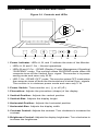
XT4888
14 INCH
COLOR MONITOR
USER'S
MANUAL
Features:
• 1024 x 768, Non-Interlaced
• .28 mm Dot Pitch
• 72 Hz Refresh Rate (VGA/SVGA)
• Power Saving Operation (VESA DPMS)
• Non-Glare Screen
• Full Screen Display
• Easy Access Front Controls
• Unlimited Palette of Colors
Part #MAN075 Rev 1.0
M1448
Table of Contents
Section 1 - General Information ........................................2
Section 2 - Installation ....................................................... 3
Section 3 - Monitor Controls and LEDs ............................. 4
Section 4 - Troubleshooting ...............................................5
Appendix A - Specifications ...............................................5
Appendix B - Video Cable Pinout ...................................... 6
Appendix C - Two Year Warranty ...................................... 7
Appendix D - Notices .........................................................8
Warning
• Read all these instructions. Save for later use.
• Do not expose this unit to rain or moisture
• Do not use this unit with an extension cord or any outlet other than a
three prong outlet.
• Do not open the cabinet. There are no user serviceable components
inside. Refer all servicing to a qualified technician.
• Do not cover the vent holes in the case. These are to allow ventilation.
• Do not insert sharp objects into the monitor. They may cause fire
accident or failure.
• The socket-outlet shall be installed near the equipment and shall be
easily accessible.
• Follow all instructions and warnings on the product.
• Do not place the product on an unstable cart.
• Operate from power source indicated on the label.
• Do not allow anything to rest on the power cord.
• Unplug this product from the wall outlet and refer servicing to qualified
service personnel under the following conditions:
A.
B.
C.
D.
E.
F.
When the power cord or plug is damaged or frayed.
If liquid has been spilled into the product.
If the product has been exposed to rain or water.
If the product does not operate normally when the operating
instructions are followed. Adjust only those controls that are
covered by the operating instructions since improper adjustment of
the other controls may result in damage and will often require
extensive work by a qualified technician to restore the product to
normal operation.
If the product has been dropped or the cabinet has been damaged.
If the product exhibits a distinct change in performance, indicating
a need for service.
1
Section 1 - General Information
Congratulations on purchasing a MaxTech 14-inch Color Monitor. The
monitor has one of the finest CRTs available in the industry, providing a
full range of video display resolutions and complies with the MPR-I
standard to reduce electromagnetic emissions.
The monitor has a 0.28 mm dot pitch display with a 65 MHz video
bandwidth. It supports video resolutions ranging from 640 x 350 to 1024
x 768 (non-interlaced).
The monitor can be used with video cards supporting VGA, SVGA, IBM
8514/A or XGA modes and provides an unlimited palette of colors.
1.1
Precautions When Using the Monitor
When setting up and using your monitor, pay special attention to the
following:
• To eliminate eye fatigue, do not use your monitor against a bright
background or where sunlight or other light sources will shine directly
on the monitor.
• Your monitor should be placed just below eye level for optimum
viewing.
• Allow adequate ventilation around the monitor so that heat from the
monitor can properly dissipate.
• Neither the monitor itself nor any other heavy object should rest on the
power cord. Damage to a power cord can cause fire or electrical
shock.
• Keep the monitor away from high capacity transformers, electric
motors and other strong magnetic fields.
• Do not use your monitor in a damp, dusty or dirty area.
• Handle the monitor with care when transporting.
• Unplug the monitor during electrical storms.
1.2
Power Saving Modes
The MaxTech monitor supports VESA Display Power Management Signaling (DPMS) SUSPEND and OFF modes. DPMS defines a method for
a computer to signal the monitor to reduce its power consumption when
idle. DPMS features must be supported by both the computer and the
monitor for them to be available. Computer support of DPMS requires the
use of a DPMS compliant video card.
The monitor enters DPMS SUSPEND mode when the computer turns off
the Vertical Synchronization signal. This power-saving mode reduces the
monitor’s power consumption to 25W. When the synchronization signal
is re-enabled the monitor returns to normal operation.
The monitor enters DPMS OFF mode when the computer turns off both the
Horizontal and Vertical Synchronization signals. This mode reduces the
monitor’s power consumption to 5W. When the synchronization signals
2
are re-enabled the monitor returns to normal operation.
Section 2 - Installation
2.1
Attaching the Base
Figure 2-1 Connecting the
Base
• Carefully place the monitor on its
side or top.
• Insert the hooks on the swivel base
into the slots in the bottom of the
monitor. Push down and forward
on the base until it snaps into place.
• Place the display upright in an appropriate location.
2.2
Connecting the Cable
• Make sure that power to the monitor and the computer is off.
• Connect the cable from the back of the monitor to the video connector
on the computer.
• Attach the power cord to the monitor and plug it into an AC outlet.
• The monitor is now ready for use.
Figure 2-1 Monitor Connections
Expansion boards
COM1
COM2
LPT1
3
VIDEO
Section 3 - Monitor Controls and LEDs
Figure 3-1 Controls and LEDs
A
B
1
C
2
3
4
5
6
7
8
9
1. Power Indicator: LEDs A, B, and C indicate the state of the Monitor.
• LEDs A, B and C On – Normal operations.
• LEDs B and C On – DPMS (Display Power Management Signaling)
“SUSPEND” mode. The monitor enters SUSPEND mode when the
computer turns off the Vertical Sync. signal. The monitor is in powersaving mode and uses only 25 W.
• LED C On – DPMS “OFF” mode. The monitor enters OFF mode when
the computer turns off both the Horizontal and Vertical Sync. signals.
The monitor is in minimum power mode and uses only 5 W.
2. Power Switch: Turns monitor on ( | ) or off ( O )
3. Pincushion: Adjusts the pincushion (shape) of the display
4. Vertical-Position: Adjusts the vertical position
5. Vertical-Size: Adjusts the display height
6. Horizontal-Position: Adjusts the horizontal position
7. Horizontal-Size: Adjusts the display width.
8. Contrast Control: Adjusts the contrast. Turn clockwise to increase the
contrast.
9. Brightness Control: Adjusts the display brightness. Turn clockwise to
increase the brightness.
4
Section 4 - Troubleshooting
No picture, power indicators A, B, C off
• Check AC cord is plugged into outlet and monitor.
• Turn on the power switch.
No picture, power indicators A, B, C on.
• Check that video cable is connected completely.
• Adjust brightness and contrast controls.
• Turn the computer on.
No picture, power indicator A off, indicators B and C on.
• Monitor is in DPMS “SUSPEND” mode. Press a key or move the
mouse.
No picture, power indicators A and B off, indicator C on.
• Monitor is in DPMS “OFF” mode. Press a key or move the mouse.
Image is not centered
• Adjust Vertical Position and Horizontal Position controls.
Appendix A - Specifications
Picture Tube
Size
14-inch diagonal
Dot pitch
0.28mm
Surface treatment Non-glare
Bandwidth
65MHz
Data Area
9.76 x 7.20 in.
Display mode
Mode
VGA I
VGA I
VGA I
VGA II
VGA II
VGA II
SVGA
SVGA
Ultra VGA
Synchronization
Resolution
640 x 350
640 x 400
640 x 480
640 x 350
640 x 400
640 x 480
800 x 600
800 x 600
1024 x 768
V. Frequency
70 Hz
70 Hz
60 Hz
84 Hz
84 Hz
72 Hz
60 Hz
72 Hz
60 Hz
Horizontal:
Vertical:
30-50 KHz
50-90 Hz
Deflection
Geometric distortion
Linearity distortion
H. Frequency
31.47 KHz
31.47 KHz
31.47 KHz
37.86 KHz
37.86 KHz
37.86 KHz
37.88 KHz
48.09 KHz
48.37 KHz
H.<=2.5mm, V.<=2.5mm
H<=10%, V<=8%
5
Pincushion distortion
High voltage regulation
<=2mm
H<=4mm, V<=4mm(0-25FL)
Low radiation*
MPR-I specification
Front controls
Power, Brightness, Contrast, Horizontal-Size, Horizontal-Position, Vertical-Size, Vertical-Position,
Pincushion
Power saving
Display Power Management Signaling (DPMS)
SUSPEND mode 25W (Max.)
OFF mode
5W (Max.)
Input voltage
100~240VAC, 50/60 Hz
Power consumption 85W maximum
Operating
Environment
Temperature
Humidity
Altitude
0°~40°C
20~90%
0~10,000ft.
Connector
15 Pin D-Sub
Dimensions
14.02 W x 14.02 H x 15.91 D
*Low radiation monitors only.
Specifications subject to change without notice.
Appendix B - Video Cable Pinout
Figure D - Pin
Layout and Pin
Assignment
Chart
11
6
1
10
15
5
PIN
SIGNAL
PIN
SIGNAL
1
Red
9
No Pin
2
Green
10
Digital Ground
3
Blue
11
Monitor Sense 1
(Jumper to Pin
10)
4
Monitor Sense 1
(Jumper to Pin 10)
12
No Pin
5
Monitor Sense 1
(Jumper to Pin 10)
13
Hor. Synch.
6
Red Return
14
Vert. Synch
7
Green Return
15
No Pin
8
Blue Return
6
Appendix C - Two Year Warranty
MaxTech warrants to the original buyer of this product against defects in
material and workmanship for two years from the date of purchase.
Except as specified below, this warranty covers all defects in material or
workmanship in this product. The following are not covered by the
warranty:
1. Any product which is not distributed in North America by MaxTech or
which is not purchased in North America from an authorized MaxTech
Dealer.
2. Any product on which the serial number has been defaced, modified
or removed.
3. Damage, deterioration or malfunction resulting from:
a. Accident, misuse, abuse, neglect, fire, water, lightning or other acts
of nature, commercial or industrial use, unauthorized product
modification, or failure to follow instructions supplied with the
product.
b. Repair or attempted repair by anyone not authorized by MaxTech.
c. Any shipment of the product (claims must be presented to the
carrier).
d. Removal or installation of the product.
e. Any other cause which does not relate to a product defect.
4. Cartons, carrying cases, batteries, external cabinets, magnetic tapes
or any accessories used in connection with the product.
MaxTech will pay all labor and material expenses for covered items, but
we will not pay for the following:
1. Removal or installation charges.
2. Costs of initial technical adjustments (set-up), including adjustment
of user controls.
3. Payment of shipping charges.
HOW TO OBTAIN WARRANTY SERVICE
If you have problems with your monitor, refer to the troubleshooting
section of this manual. If you are unable to resolve the problem, contact
the dealer or distributor from whom the product was purchased. A
defective monitor should be returned in its original packaging to your
dealer for warranty service.
LIMITATION OF IMPLIED WARRANTIES
All implied warranties, including warranties of merchantability and fitness
for a particular purpose, are limited in duration to the length of this
warranty.
EXCLUSION OF DAMAGES
MaxTech'S liability for any defective product is limited to the repair or
replacement of the product, at our option. MaxTech shall not be liable for:
1. Damage to other property caused by any defects in this product,
7
damages based upon inconvenience, loss of use of the product, loss
of time, commercial loss; or
2. Any other damages, whether incidental, consequential or otherwise.
Some states do not allow limitations on how long an implied warranty lasts
and/or do not allow the exclusion or limitation of incidental or consequential damages, so the above limitations and exclusions may not apply to
you.
HOW STATE LAW RELATES TO THE WARRANTY
This warranty gives you specific legal rights, and you may also have other
rights which vary from state to state.
Appendix D - Notices
FCC Class B Statement
This equipment has been tested and found to comply with the limits for a
Class B digital device, pursuant to Part 15 of the FCC Rules. These limits
are designed to provide reasonable protection against harmful interference in a residential installation. This equipment generates, uses and can
radiate radio frequency energy, and if not installed and used in accordance
with the instructions, may cause harmful interference to radio communications. However, there is no guarantee that interference will not occur in
a particular installation. If this equipment does cause harmful interference
to radio or television reception, which can be determined by turning the
equipment off and on, the user is encouraged to try to correct the
interference by one or more of the following measures:
• Reorient or relocate the receiving antenna
• Increase the separation between the equipment and the receiver
• Connect the equipment into an outlet on a circuit different from that
to which the receiver is connected
• Consult the dealer or an experienced radio / TV technician for help
Notice: Shielded cables, if any, must be used in order to comply with the
emission limits.
Notice: Any change or modification not expressly approved by the
Grantee of the equipment authorization could void the user’s authority to
operate the equipment.
Canadian DOC Compliance Statement
This equipment does not exceed Class B limits for radio noise emissions
for a digital apparatus, set out in the Radio Interference Regulations of the
Canadian Department of Communications.
DOC Avis de Conformation
Le présent appereil numérique n'émet pas de bruits radioélectriques
8
dépassant les limites applicables aux appareils numériques de la class B
prescrites dans le Règlement sur le broullage radioélectrique édicté par
le ministère des Communications du Canada
Disclaimer, Copyright, And Other Notices
The information contained in this manual has been validated at the time
of this manual's production. The manufacturer reserves the right to make
any changes and improvements in the product described in this manual
at any time and without notice. Consequently, the manufacturer assumes
no liability for damages incurred directly or indirectly from errors, omissions or discrepancies between the product and the manual.
All registered trademarks are the property of their respective owners.
Copyright © 1996 MaxTech. All rights reserved. No reproduction of this
document in any form is allowed without written permission from MaxTech.
First Edition
GZ/DR - Version 1.0
9