1
J
MARINE DIESEL ENGINE
MODELS:
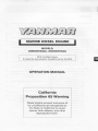
2GM20(F)M(C), 3GM30(F)M(C)
EPA Certified Engine
It meets the low emission standards set by the EPA
OPERATION MANUAL
California
Proposition 65 Warning
Diesel engine exhaust and some of
its constituents are recognized by
the State of California to cause
cancer, birth defects, and other
reproductive harm.
Contents
CONTENTS
INTRODUCTION ...............................................3
3.3.4 Cautions during Operation ......30
3.3.5 Stopping the Engine ...............30
1
3.4 Long term Storage ............................32
FOR YOUR SAFETY ....................................4
1.1 Warning symbols ................................ .4
1.2 Safety Precautions ............................. .4
1.3 Warning Labels ...................................?
4
MAINTENANCE & INSPECnON ...............34
4.1
General Inspection Rules ..................34
4.2 List of Periodic Inspection ltems ....... 35
2
PRODUCT EXPLANATION .......................... 8
2.1
4.3 Periodic Inspection ltems ..................37
Use, Driving System etc ...................... 8
4.3.1 Inspection on Initial 50 Hrs. of
2.2 Engine Specifications .......................... 9
Operation (or after 1 month) ....37
2.3 Names of Parts ..................................15
4.3.2 Inspection Every 50 Hours
2.4 Major Servicing Parts ........................ 16
(or monthly) ............................. 37
2.5 Control Equipment ............................ 17
4.3.3 Inspection Every 150 Hrs ........ 39
2 .5.1 Control Panel ......... ................. 17
4.3.4 Inspection Every 300 Hrs ........ 39
2.5.2 Single Lever Remote
4.3.5 Inspection Every 600 Hrs ........ 40
Control Handle ........................ 19
4.4 EPA Requirements ........................... .41
2.5.3 Stopping Equipment ............... 19
4.4.1 EPA Certification Plate ............ 41
2.5.4 Decompression Equipment... .. 19
4.4.2 Conditions to Insure
Compliance with Emission
3
OPERATION ..............................................20
3.1
Standards .............................. ..42
Fuel Oil, Lube Oil & Cooling Water.... 20
4.4.3 Inspection and Maintenance ...44
3.1.1 Fuel Oil .................................... 20
4.4.4 Emission System Warranty
3.1.2 Lube Oil ............... .................... 21
Statement ................................44
3.1.3 Cooling Water ......................... 21
3.2 Before Initial Operation ..................... 22
5
TROUBLE AND TROUBLESHOOTING .... .45
6
PIPING DIAGRAMS ...................................48
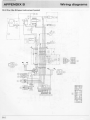
7
WIRING DIAGRAMS ..................................50
3.2.1 Supply Fuel 011 ........................22
3.2.2 Supply Engine Lube 011 ........... 22
3.2.3 Supply Clutch Lube Oil ...........23
3.2.4 Supply Cooling Water ............. 23
3.2.5 Cranking (Idling) ...................... 24
3.2.6 Check and Resupply Lube
Oil and Cooling Water .............25
3.3 Operating your Engine ......................25
3.3.1 Inspection Before Starting ...... 26
3.3.2 How t o Start the Engine ..........27
3.3.3 Operation ................. ...............29
2
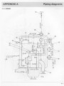
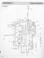
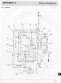
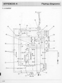
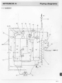
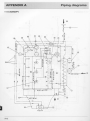
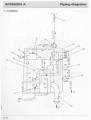
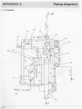
APPENDIX A (Piping diagrams) .....................A-1
(See the back of this Manual)
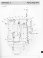
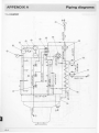
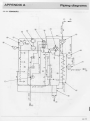
APPENDIX B (Piping diagrams) .................... B-1
(See the back of this Manual)
Introduction
Thank you for purchasing a YANMAR Marine Diesel Engine.
This Operation Manual describes the operation. maintenance and inspection of the
2GM20(F)M(C), 3GM30(F)M(C) Yanmar Marine Diesel Engines.
Read this Operation Manual carefully before operating the engine to ensure that it is used
correctly and that it stays in the best possible condition.
Keep this Operation Manual in a convenient place for easy access.
If this Operation Manual is lost or damaged, order a new one from your dealer or
distributor.
Make sure this manual is transfered to subsequent owners. It should be considered as a
permanent part of the engine and remain so.
Constant efforts are made to improve the quality and performance of Yanmar products,
so some details included in this Operation Manual may differ slightly from your engine. If
you have any questions about this, please contact your Yanmar dealer or distributor.
The marine gear described in this manual is Yanmar Model KM Series.
Operation Manual
(Marine Engine)
Models
2GM20(F)M(C),
3GM30(F)M(C)
Code. No.
499611 - 00680
With regard to the sail drive, this manual describes lube oil selection and specification
only. Please read the Sail Drive Operation Manual, which is supplied with the Sail Drive
Unit, for further information.
3
1. For your safety
1.1 WARNING SYMBOLS
Most operation, maintenance and inspection problems arise due to users' failure to
comply with the rules and precaut1ons for safe operation described in this operation
manual. Often, users do not understand or recognize the signs of approaching problems.
Improper handling can cause burns and other injuries and can result in death.
Be sure to read this operation manual carefully before operating the engine and observe
all of the instructions and precautions described in this manual.
Below follow the warning signs used in this manual. Pay special attention to parts
containing these words and signs.
A
A
A
DANGER
DANGER indicates an imminently hazardous
situation which, if not avoided, WILL result in death
or serious injury.
WARNING
WARNING indicates a potentially hazardous situation which, if not avoided, COULD result in death or
serious injury.
CAUTION
'
CAUTION indicates a potentially hazardous situation which, if not avoided, may result in minor or
moderate injury.
This sign is also be used to alert against unsafe
practices.
are particularly important cautions for
The descriptions captioned by
handling. If you ignore them, the performance of your machine may deteriorate leading to
problems.
1.2 SAFETY PRECAUTIONS
(Observe these instructions for your own safety!)
Precautions for Operat ion
A DANGER
4
Filler Cap of Fresh Water Tank
Never open the cap of the fresh water tank while the engine is still hot.
Steam and hot water will spurt out and burn you seriously. Wait until
the temperature of the fresh water tank has dropped, wrap a cloth
around the filler cap and loosen the cap slowly. After inspection,
refasten the cap firmly.
1. For your safety
A
DANGER
Battery
Never smoke or permit sparks near the battery, because it may emit
explosive hydrogen gas. Place the battery in a well-ventilated place.
A
DANGER
Fuel
Use only diesel oil. Never use other fuels, including gasoline, kerosene,
etc. , because they could cause a fire. The wrong fuel could also cause
the fuel injection pump and injector to fail due to lack of proper
lubrication. Be sure to check that you have selected the correct diesel
fuel before filling the fuel tank.
Fire Prevention
Be sure to stop the engine and confirm that there are no open flames
in the vicinity before supplying fuel. If you do spill fuel, wipe such
spillage carefully and dispose of the wiping materials properly. Wash
your hands thorougly with soap and water.
Never place oil or other flammable material in the engine room.
Install a fire extinguisher near the engine room, and familiarize yourself
with its use.
Exhaust Gas
Exhaust gas contains poisonous carbon monoxide and should not be
inhaled.
Be sure to install ventilation ports or ventilators in the engine room and
ensure good ventilation during engine operation.
A
WARNING
Moving Parts
Do not touch or let your clothing get caught in the moving parts of the
engine, such as the front drive shaft, V-belt or propeller shaft, during
engine operation. You will be injured.
Never operate the engine without the covers on the moving parts.
A
CAUTION
Burns
The whole engine is hot during operation and immediately after
stopping. The exhaust manifold, exhaust pipe and high pressure fuel
pipe are very hot. Never touch these parts with your body or clothing.
I
I
5
1. For your safety
A
WARNING
Alcoho l
Never operate the engine while you are under the influence of alcohol.
Never operate the engine when you are ill or feeling unwell.
SAFETY PRECAUTIONS FOR INSPECTION
A
DANGER
Battery Fluid
Battery fluid is dilute sulfuric acid. It can blind you if it gets In your
eyes, or burn your skin. Keep the fluid away from your body. If you
touch It, wash it off immediately with a large quantity or fresh water
and call your doctor for treatment.
A
WARNING
Fire by Electric Short- Circuits
Always turn off the battery switch before inspecting the electrical
system.
Failure to do so could cause short-circuiting and fires.
A
WARNING
Stop the engine before servicing
Stop the engine before you service it.
Turn the battery switch off. If you must inspect while the engine is in
operation, never touch moving parts. Keep your body and c lothing well
clear of all moving parts.
-•
• _1 \..
7
~'t
Scalds
If extracting oil from the engine while it is still hot, don't let the oil
splash on you.
Wait until the temperature has dropped before extracting cooling water
from the engine. Don't let it splash on you.
A
CAUTION
A
DANGER
Forbidden Modifications
Never release the limiting devices such as the engine speed limit, fuel
injection limit, etc.
Modification will impair the safety and performance of the product and
shorten product life.
Also note that any troubles arising from modification are not covered
by our warranty.
A
DANGER
Precautions for Treating Waste
Never dispose of waste oil or other fluid in a field, sewer, river. or the
sea. Treat waste matters safely observing regulations or laws.
Ask a waste recovery company to collect it.
6
1. For your safety
SAFETY PRECAUTIONS FOR INSPECTION
1.3 WARNING LABELS
To insure safe operation, warning device
labels have been attached. Their location is
shown below and they should always be
visible. Please replace if damaged or lost.
Warning Device Labels, Parts Numbers
~
~No.
CD
@
Part Code No.
---
128296-07350
128296-07260
l!!l
E
•~hell
• Aota tlno porto .
• C• n ce uee l"jury.
Ul2t l
_r;;..!.;;
.
Lr
...:::::::!
07)~0
~
2GM20(C)M. 3GM30(C)M
e•
DANGER
••iiJWt=~:f,. :;~ :TI!RI1
g:~n:"Fi! ~ '· •llilbl ~ ~
tiJ t..\'>l:t ~ ~T~!!ln~IJ.
ollovor removo tho cep whllt tho onoino
11 11111 hot. • Hot water mor 1purt out
end burn you.
2GM20F(C)M. 3GM30F(C)M
7
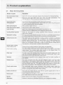
2. Product explanation
2.1 USE, DRIVING SYSTEM, ETC.
The engine is equipped with marine gear, connect the marine gear output shaft to the
propeller shaft.
In order to obtain full performance from your engine, it is imperative that you check the
size and structure of the hull and use a propeller of the appropriate size.
The engine must be installed correctly with safe cooling water and exhaust piping and
electrical wiring. The PTO work should be easy to use for onboard equipment.
To handle the drive equipment, driven systems (including the propeller) and other onboard
equipment,be sure to observe the instructions and cautions given in the operation
manuals supplied by the shipyard and equipment manufacturers.
The laws of some countries may require hull and engine Inspections, depending on the
use, size and cruising area of the boat.
The installation, fitting and surveying of this engine all require specialized knowledge and
engineering skills. Consult Yanmar's local subsidiary in your region or your distributor or
dealer.
A
WARNING
Never modify this product or release the limit devices (which limit engine
speed. fuel injection quantity, etc.). Modification will impair the safety and
performance of the product and functions and shorten the product life.
Please note that any troubles arising from modification of the product will not
be covered by our warranty.
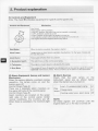
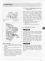
DETAIL OF NAME PLATE
The name plate shown below is attached
to the engine. Check the engine's model,
output, rpm and serial number on the
name plate.
MODEL
CONT.RATING
MAX.OUT PUT
ENGINE NO.
kW
rpm
kW
rpm
The name plate shown below is
described in the marine gear. Check the
marine gear's model, gear ratio, oil used,
oil quantity and serial number.
v
YliUfMA8 D~DHI.-E
__
MOD EL
GEAR RATIO
OIL
OIL QTY.
NO.
KM
SAE20IJoHD
LTR.
KIIIIZAICI
..)
8
OSAKA
,
JAPAN
~
•
2. Product explanation
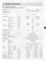
2.2
Engine Specifications
2.2.1 Direct Seawater Cooling Type, GM series
I Engine Model _ _ _ __
~ - -- - -
I
2GM20
3GM30
Vert•cal4·cycle water cooled diesel engine
- +--------
CombuStiOn system
------------4---------+-----
Number of cylinders
+-------
Bore x stroke
mm (ln .)
Displacement
(!;u.m.)
Swart pre-combustion chamber
2
3
75
X
72 (2.95
X
I
0.636 (38.81)
0 954 (58.21)
I
17 7/3400
OutpuVcrankshaft
kW/rpm
11.8/3400
speed
IHP/mml
(16.0/3400)
Continuous
Brake mean
kg/em
rating output
effectiVe pressure
(lb./in. 1
(94.7 1)
m/sec.
8.16
Piston speed
2.83)
(24 1/3400)
6.66
(26.77)
(ft./sec.\
OutpuVcrankshaft
kW/rpm
13.4/3600
20.1/3600
One hour
speed
HP/rR.m
(18.2/3600)
(27.313600)
rating output
Brake mean
kg/em
effective pressure
lb./in.)
(100.54)
m/sec.
8.64
(11./sec.)
(28.35)
~
Piston speed
7.07
Compression ratio
23.0
Fuel injection tim1ng (b.T.D.C.)
18±1
15±1
Fuel injection pressure
kg/em
170:5
jlb.lin )
(234 7 - 2489)
Main power take off
at Flywheel side
Front power take off
at Crankshaft V-pulley side
- -- -- - -
-----
Direction of
Crankshaft
rotation
Propeller shaft (Ahead)
Cooling system
------
Counter-cloc kwise viewed from stem
~--~---
Complete enc Josed forced lubncauon
~-'-'---
system
Clockwise viewed from stern
Dttect seawater cooll ng _(rubber Impeller water pump)
Lubrication system
Startang
-
Type
Electnc and manual
DC 12V, 1.0kW
Starting motor
12V. SSA
AC generator
KM2P
Model
1
KM3P
e clutch with single stage
Type
ahead and astern
Marine gear
system
Reduction
ratio
Propeller
speed
.22
2.21
2.62
Reverse
.06
3.06
3.06
3.16
1540
1298
1063
1113
1113
1076
---.------
Forward
rpm
Reverse
rpm
~;_:_:=--j--
Lubricating oaf capacity
Dimensions
I
Forward
(cu.an.)
113
I
3.20
0.3 (18.31}
0. 35(21 .36)
11.5(25.361
Weight
kg (lb.)
10.3 (22.71)
Overalllenglh
----Overall width
mm (in.)
735 (28.9)
740(29 13)
...;_
mm (ln.)
455 (17.91)
455(11.91)
Overall height
mm Qn.)
495 (1950)
~95(19 5())
2.6 (158 65)
1.6 (97.63)
2.6(15865l
161'3763)
129 (283.8)
1301280)
9
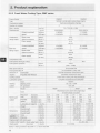
2. Product explanation
2.2.2 Fresh Wat er Cooling Type, GMF series
3GM30F
I
Vert1cal 4-cycle w ater cooled diesel engine
2GM20F
Eng1ne Model
Type
1-----_ _ _ _ _ _Swirl pre-c ombustlon chamber
Combustion system
I
2
Number of cylinders
Bore • stroke
mm (tn.)
Displacement
(cu.in.)
75 )( 72 (2.95 )( 2.83)
0.636 (38.81)
0.954 (58.21)
kW/rpm
11.8/3400
17.7/3400
speed
(HP/rpm)
(16.013400)
(2A 1/3400)
Continuous
Brake mean
kg/em
6.66
rahng output
effective pressure
(lbJin:')
(94.71)
Piston speed
m/sec.
8.16
(26.77)
(ft./sec.)
~
liiil
3
OutpuVcrankshaft
OutpuVcrankshaft
kW/rpm
13.4/3600
20.1/3600
One hour
speed
(HP/rpm)
(18.2/3600)
(27 .3/3600)
rating out put
Brake mean
kg/em'
7 07
effective pressure
(lb./ln. )
(1 00.54)
m/sec.
8.64
j{ft.tsec.)
(28.35)
L
Piston speed
Compress1on r atio
23.0
FuellnJechon t 1mmg (b.T.D.C.)
15:t1
18±1
170:t5
kg/em
Fuel intecllon pressure
(2347
_ QbJin.)
2489)
Matn power tak eoff
at Flywheel side
Front power ta keoff
at Cran kshaft V-pulley side
Direction of
Complete en closed forced lubrication
Type
Electric_ __ _ __
·- -·
Start1ng motor
DC 12V,l.OkW - -- - - -
____
12V.55A
:..:.._
AC generator
-'-
KM2P
Model
__,
~
KM2P
KM3P
Mechanical cone clutch w1th single s1age
Type
system
1
Fresh water c ooling with heat e:::.x..:c_han=g~er:___ _~--t
Lubrication system
Marine gear
-
Clockwt se viewed from stern
Cooling system
~tern
-
Counter·clockwlse viewed from stern
Crankshaft
rotallo_n_ _ Propeller shaft (Ahead)
Starling
-
for bothahead and astern
•
Reduction
Forward
ratio
Reverse
Propeller
speed
Forward
f=------,,..----1
3.22
2.21
2.62
3.20
~3...:..06=--+~3.06 _+-....;3.06
3.06
3.06
3.16
1540
1298
1063
1113
1113
1076
2.21
2.62
0.3 (18.31)
0.35(21.36)
10.3 (22.71)
11.5(25.36)
735 (28.93)
745(29.33)
455 (17.91)
455(17.91)
545 (21 .45)
545(21 .45)
Lubricahng oil
--+2.6 {158.65)
2.6(158.65)
(rake artgle 8•)
1.6 (97.63)
1.6(97.63) -
Engine we1ght with marineg
.,_e:..:car=-----+
137 (301.4)
138(303.6)
~aoacttv
Cooling water capacity Fresh water tank ' (cu.ln.)
(fresh water)
Sub-tank
' (cu.ln.)
+----
(Note) 1 Rating condition: ISO 3046-1. 2. 1hp .0.7355 kW.
10
3.4 (207 .48)
0.8 (48.82)
-
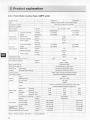
2. Product explanation
2.2.3
Direct Seawater Cooling Type, GMV series
IEnglne Model
2GM20v
3GM30V
Vert~eal4- cycle water cooled diesel eng•'le
'
,_
Type
Number of cylinders
I
2
Bora x stroke
mm (ln.)
Dlsplacement
(cu.in.)
75
72 (2 .95
X
2.83)
0.636 (38. 81)
0.954 (58.21)
kW/rpm
11.813400
17.713400
speed
(HP/rpm)
(16.0134 00)
(24 113400)
Continuous
Brake mean
kg/em
rating output
effectiv~e...!:p::.:re:.:s:::su::.r.:.e_ _-1-~
(lb::::./~ln.::..'l!-_-+--------
6.66
(94 .71)
8.16
m/sec.
Piston speed
(26 .77)
---1--....!:.(ft=-Jsee.)
OutpuVcrankshaft
kW/rpm
13.4/3600
l
20.1/3600
One hour
speed
(HP/rpm)
rabng output
Brake mean
kg/em
7.07
effective pressure
(lb./in.)
(100.54)
mlsec.
8.64
(ft./sec.)
(28.35)
Piston speed
_,__
_.!..(1:..::;8213600)
Compression;_r.::
a.::.
tio:___ __
Fuel Injection timing (b.T.D C.)
----+-
rotation
170±5
Qb.lin. i
(2347- 2489)
at Flywheel side
at Crankshaft V-puliey side
1Propeller shafl (Ahead)
Direct seawater coo ling (rubber impeller water pump)
Complete enclosed forced lubrication
I
Type
!Starting motor
Electric and manual
DC 12V, 1.0kW
AC generator
12V,55A
Dimensions
LubriC~~bng oil
a le 8j
rrnreCl~
for both ahead and astern (Angle 15 )
Forward
2.61
320
Reverse
316
3.16
Propeller
speed
Forward
rpm
1303
1063
Reverse
rpm
1076
i
-
1076
Lubrlcabng oil capacity
' (cu.ln.)
0,8 (48.92)
We1ght
kg (lb.)
19.5 (43.0)
Overall length
mm Qn.)
486 (19.13)
591.5 (23.29)
Overall width
mm (in.)
455 (17.91)
455 (17.91)
Overall hetght
mm (in.)
495 (19.49)
495 (19.49)
Total
' (cu. ln.)
2.0 (122.05)
2.6(158 65)
1.3 (79.33)
1.6 (97 .63)
Engine weight with marine gear
-
V-drlve. mechanical cone clutch with single stage
Reduction
ratio
JEttective
-
KM3V
t-
Type
system
_ ____:::_CI:.:.OC::;,kwlse viewed from stern
Clockwise viewed from stern
' Model
Marine gear
-
------------·!------
· atloo system
Lubnc
system
18%1
----
kg/em
Cool tng system
Start •ng
15±1
I
Cranksh.:.::a:;,:fl~---------+--
Direction of
(27.313600)
23.0
Fuel Injection pressure
1
X
3
OutpuVcrankshaft
Matn power take off
Front power take off
·-
Swi rt pre-combustlon chamber
C ombusllon system
(cu.in.) _
kg (lb.)
(Note) 1. Rating condition: ISO 3046·1. 2. lhp=0.7355 kW.
119 (261)
-
138 (303)
-L---
--~
11
r
2. Product explanation
2.2.4 Fresh Water Cooling Type, GMFV series
}
Eng! ne Model
Type
2GM20FV
3GM30FV
Vertical 4-cycle water cooled diesel engine
Swirl pre-combustion chamber
Combustion system
Number of cylinders
2
Bore x stroke
mm On.)
Displacement
(cu.in.)
rating output
1-
X 72
3
(2.95 X 2.83)
0.636 (38.81)
0.954 (58.21)
Output/crankshaft
kW/rpm
11.813400
17.7/3400
speed
,(tiP/rpm)
kg/em
(16.0/3400)
(24.1/3400)
Brake mean
ContJnUOUS
75
l
effectiVe pressure
Piston speed
6.66
ObJin)
m/sec.
(94.71)
(fl./sec.)
(26. 77)
8.16
Out put/crankshaft
kW/rpm
13.4/3600
20.1/3600
One hour
speed
(HP/rpm)
(18.2/3600)
(27.3/3600)
rahng output
Brake mean
kg/em
7.07
effective pressure
,Ob./in.')
(1 00.54)
mlsec.
8.64
Piston speed
(ftJsec.)
(28.35)
CompressiOn ratio
23.0
Fuel tntection tim1ng (b.T.D.C.)
15±1
-
Fuel Injection pressure
I
kg/em·
170±5
(lb./in.')
(2347- 2489)
Main power take oN
at Flywheel s1de
Front power take off
at Crankshalt V-pulley side
Dlrec lion of
rotat ion
I
Clockwise viewed from stern
Crankshaft
Propeller shaft (Ahead)
Clockwise viewed from stem
Cool lng system
Complete enclosed forced lubrication
Type
Electric
Starting
Starting motor
DC 12V, l.OkW
system
AC generator
12V.55A
V-drlve, mechanical cone clutch with single stage
for both ahead and astern (Angle 15 •)
Type
Reduction
ratio
1Propeller
Ispeed
Forward
2.36
2.61
3.20
Reverse
3.16
3.16
3.16
Forward rpm
1441
1303
1063
Reverse rpm
1076
1076
1076
f-
Lubricating 011 capac•ty
D1menslons
0.8 (48.92)
(cu.ln.)
WeJQhl
~g (lb.)
Overall length
mm Qn.)
491 (19.33)
576 (22.68)
Overall width
mm Qn.)
482 (19.00)
455 (17.91)
Overall height
mm (in.)
545 (21.46)
545 (21.46)
(cu.in.)
2.0 (122.05)
2.6 (158.65)
· (cu.ln.)
kg (lb.)
1.3 (79.33)
1.6 (97.63)
125 (278)
147 (323)
Lubrl Cffling oil Total
a gle 8") Effective
fr~~~c~
Engine weight with marine gear
(Note) 1 Rating condition: ISO 3046·1 2. 1hp=O.7355 kW
12
·,
KM3V
Model
system
-
Fresh water cooling with heat exchanger
Lubnca
" t10n system
Marin e gear
18±1
-
19.5 (43.0)
-
2. Product explanation
2.2.5 Direct Seawater Cooling Type, GMC series
2GM20C
3GM30C
Vertical 4-cycle water cooled diesel engine
Combustion system
Swirl pre-combustion chamber
Number of cylln~d:..:e~
rs:..___ _ __
I
2
Bore x stroke
mm (in.)
Dasptacement
(cu.ln.)
75
X
0.954 (58.21)
Output/crankshaft
kW/rpm
speed
(HP/rpm)
Continuous
Brake mean
kg/em
rating output
effective pressure
(lb./ln.)
(94.71)
m/sec.
8.16
(ft./sec.)
(26.77)
Piston speed
17.713400
11.8/3400
(16.0/3400)
(24.113400)
6.66
I
Output/crankshaft
kW/rpm
13.4/3600
One hour
speed
(HP/rpm)
(18.2/3600)
raltng output
Brake mean
kg/em
7.07
effecttve pressure
Ob./in.)
(100.54)
m/sec.
8.64
(28.35)
Ptston speed
-
Fuellnjection pressure
23.0
• ·-
Fuellnject•o n tomlng (b.T.D.C.)
20.1/3600
(27 .313600)
(f1Jsec.)
Compresston ratio
15:d
18:t1
kg/em
170±5
(lb./in:)
(2347- 2489)
Matn power take off
at Flywheel side
Front powe r take off
at Crankshaft V·pulley side
Direction of
Crankshaft
rota !ton
Propeller shaft (Ahead)
Counter-clockwise vtewed from stem
t~
Clockwtse viewed from stem
Cooling systern
Direct seawater cooling (rubber impeller water pump)
Lubrication system
1
Starttng
system
Complete enclosed forced lubncation
Type
Electric and manual
Starting motor
DC 12V, 1 OkW
AC generator
12V.55A
Model
Type
Sail drive
system
Dtmens10ns
·-
72 (2.95 X 2.83)
0.636 (38.81)
-
3
-
-
SD20
Sail drive unit- Dog type clutch, spiral bevel gear type
Reduction
Forward
ratio
Reverse
Propeller
Forward
rpm
1290
speed
Reverse
rpm
1290
2.64
mm (in.)
503 (19.80)
591.5 (23.28}
Overall width
mm Qn.)
455 (17.91)
455 (17.91)
Overall hetght
mmOn.)
4~5
495 (19.50}
Engine welghi Wtlh saO drive
-
2.64
Overall length
Lubricating oil Total
capac tty
(rake angle 8') Effective
--
(19.50)
(cu.tn.)
2.0 (122.03}
(cu. ln.)
1.3 (79.32)
1kg (lb.)
134 (294.8)
-
2.6 (158.65)
1.6 (97.63)
153 (336.6)
(Note) 1. Rating condition: ISO 3046-1. 2. 1hp-0. 7355 kW.
(Note) Sail drive unit will be coupled with the engine In the market.
13
2. Product explanation
2.2.6 Fresh Water Cooling Type, GMFC series
Eng1ne Model
2GM20FC
3GM30FC
Vertical 4-cycle waler cooled diesel engine
-
Type
Combustlon system
Swirl pre-com bustlon chamber
Number of cylinders
[
2
75
-3 ---1
Bore x stroke
mm (in.)
D•splacement
.· (cu.ln.)
0.636 (38.81)
Output/crankshaft
kW/rpm
11 .813400
17.7/3400
speed
(HP/rpm)
(16.013400)
(24.1/3400)
Continuous
Brake mean
kg/em
6.66
rating output
effective pressure
(lbJ1n.)
(94.71)
Piston speed
m/sec.
8.16
(ft ./sec.)
(26.77)
X
72 (2.95 X 2.83)'---0.954 (58.21)
l
Output/crankshaft
kW/rpm
One hour
speed
rating output
Brake mean
(H P/rpm.:..)- 1 - - --..!.(1;_:8,;;:
.213
;_:;.::
6;:.:
00:!..
)_
kg/em
effective pressure
(lb./In )
(100.54)
mlsec.
8.64
Piston speed
13.4/3600
(27.3/3600)
(ftlsec
~.)__;_-----~-- (28.35)
230
Fuel Injection t1ming (b.T.D.C.)
Fuel Injection press ure
kg/em
(lb./ln.)
Main power taKe o ff
I
15±1
-
18±1
170±5
(2347- 248-'-'9)_ _ __
at Flywheel side
-
Front power take off
at Crankshaft V-pulley side
Direction of
Cranks haft
rotation
p ropeller shaft (Ahead)
------
Counter-ctoc kwise viewed from stern
Clockwlse viewed from stem
Cooling system
Fresh water coollng w1th heat exchanger
l lubncahon system
Complete enctosed forced lubncatJon
r
r;
ype
system
.
20.1/3600
7 07
Compression ratio
Starting
-
Electnc
c-
tarting motor
D 12V, l.OkW
12V.55A
AC generator
Model
Type
SD20
Sail drive unit - Dog type clutch, spiral bevel gear type
~
Sail drtve
Reduction
Forward
2.64
system
ra lio
propeller
Reverse
2.64
s peed
Forward rpm
Reverse rpm
0 veralllength
D1mens10ns
--
1290
mm (in.)
508 (20.00)
593 (23.34)
Overall w•dl_h_ _ _ _,_
m_m
_,_
(ln-'-.)
482 (18.97)
455 (17.91)
mm (1n.)'--_ _ _ _..:54c.:.5::...!(21.45)
Overall he•ght
lubricat•ng ~I Total
(CU.In.)
2.0 (122.03)
(raKe arlgle 81 Effective
(cu.1n.)
1.3 (79.32)
545 (21.45)
2.6 (158.65)
1.6 (97.63)
142 (312.4)
161 (354.2)
2.9(176.97)
3.4 (207 48)
~aCitY
Engine weight w•th sail drive
kg (lb.)
I
Cooling wa ter capacity Fresh water tank 1 (cu. in.)
1
1290
-
esh wate r)
Sub-tank
, (cu.ln.)
(Note) 1 Rating condition: ISO 3046-1 . 2. 1hp::0.7355 kW.
(Note) Sail drive unit will be coupled wi th the engine In the market.
14
-
"
0.8 (48.82)
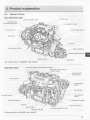
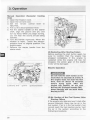
2. Product explanation
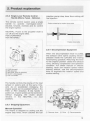
2 .3
Names of Parts
Non Operation Side
Oil filler cap
Decompression lever
Cooling water
temperature sender
/
Fuel InJeCtion valve
Tachometre sensor
Intake silencer
Alternator -
Dipstick
Lubricating oil filter
,.,.-Manne gearbox
Output shaft coupling
Starter motor
Shift lever
Air intake side of 3GM30F with KM3P
Operation Side
Heat exchanger and exhaust manifold
Rller cap (with pressure
control valve)
/
Cooling fresh
water pump
/
Mixing elbow
- - -Fuel injection
pump
Idle adjuster
Fuel feed pump -
-
Mounting flange
Dipstick
Fuel oil filter
Crankshaft V-pulley
Engine stop lever
I
Regulator handle
Fuel Injection
limiter
Cooling seawater pump
Exhaust side of 3GM30F with KM3P
15
2. Product explanation
2.4
Major Servicing Parts
Name of part
Function
Decompression lever
Opens thee xhaust valve and releases the pressure for manual starting.
Fuel filter
Removes d ust and water from fuel. Drain the filter periodically. The
internal elem ent (filter) should be changed periodically.
-
Fuel feed pump,
Priming lever
Feed fuel to the fuel injection pump. Moving the priming
lever up and down feeds the fuel. When there is no fuel, the priming lever
is used to b leed air from the fuel system.
Filler port (engine)
Filler port fo r eng1ne lube oil.
Filler port (marine gear)
Filler port fo r marine gear lube oil.
Lube oil filter
Filters fine metal fragments and carbon from the lube oil.
Filtered lube oil is distributed to the engine's moving parts.
----
---1--
Cooling Water System
There are two types of cooling systems: direct seawater cooling and
fresh water cooling.
Seawater cooling
The seawat er pump feeds seawater. The flow is controlled automatically
by a thermostat which measures the temperature during operation.
Anticorrosion zinc
The metal area of the seawater cooling system is prone to electrical
corrosion. The anticorrosion zinc is Installed in the cylinder block and/or
cylinder head to prevent this. The anticorrosion zinc is Itself reduced over
time by ele ctrical corrosion, so It must be replaced at fixed intervals
before It is c ompletely consumed In order to ensure that the metal area of
the seawater cooling system remains fully protected.
Fresh water cooling
Fresh water pump
Fresh water coolmg
Filler cap
There are tw o cooling systems: fresh water and seawater.
The fresh wa ter pump is run by the alternator and the V-belt.
The fresh w ater in the fresh water cooler is fed to the engine by the fresh
water pump. The cooling fresh water returns to the eng1ne after it is
cooled with seawater in the fresh water cooler.
The filler cap on the cooling water tank covers the water supply port. The
cap has a p ressure regulating valve. When the cooling water temp. rises,
the__:__
pressure rises inside the fresh water cooler.
______
Subtank
The pressure regulating valve releases vapor and hot water overflow to
the subtank
The hose c onnects the filler cap and subtank. Vapor and hot water
discharged to the subtank return there to the cooling water. When the
engine stop s and cooling water cools, the pressure In the cooling water
tank also drops very low. The fi ller cap valve then opens to send water
back from th e subtank. This min1mizes cooling water consumption.
Fresh water pump
The centrifu gal water pump circulates fresh cooling water inside the
engine. The pump and alternator are dnven by the V-belt. The fresh water
pump is on engines using fresh water cooling.
Intake air silencer
This is the alr Intake silencer. The silencer guards against dirt in the air
and reduces the noise of air intake.
----1--
Name plate
Starter
Alternator
16
Name plate s are provided on the engine and the marine gear and have
the model, serial number and other data.
---l--Starter motor for the engine. Powered by the battery.
Rotates by b elt drive, generates electricity and charges the battery.
2. Product explanation
2 .5 Control Equipment
The equipment in the control room, making remote control possible, consists of: the
instrument panel, which is connected by wire harness; the remote control handle, which is
hooked up by remote control cable to each of the engine control levers, and the stopping
equipment.
2.5.1 Control Panel
Electric Operation
There are two control panel options. The controls and alarm lamps included are shown
below.
(B)
(A)
a>
®
\
CD
@
I
I
@
\
@
®
\
I
0
~-----~~~0~-40
I
@
\
®
Q)Water Proof (sail dnve)
@ High temp. cooling water
G)Low lube oil pressure
®
@ Charge
@ Key SWitCh
@ Buzzer
\
\
(j)
\
\
®
®
Q)Start switch
@Tachometre
® Illumination sw1tch
17
2. Product explanation
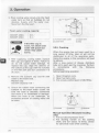
2.5.2 Single Lever Remote Control
Handle (Morse Type) - Optional.
injection pump stop lever thus cutting off
fuel injection.
This remote control system uses a single
handle to operate marinegear-clutch(neutral, forward, reverse) and to control
the engine speed.
Engine stopp1ng by engine stop cable
NEUTRAL Power to the propeller shaft is
cut off and the engine idles.
FWD (FORWARD)
REV (REVERSE)
Engine stop cable
CD
2.5.4 Decompression Equipment
..
..
'
••
••
'.,.
..
:
I
·..
.'
· -'f-~·;'
/
""-
:'
•• , ••
./
1"\~ .- -
~
..
.
.
--.-t-- •
........
•
•
•
CD
FWD (forward)
@ REV (reverse)
@ NEUTRAL (boat is stopped)
@ Clutch is disengaged
® Pull out handle
When the decompression lever is pulled,
the exhaust valve opens causing decompression inside the cylinders and making
hand-turning possible. Returning the lever
to the original position closes the exhaust
valve, allowing compression and operation
condition. For either manual or electric
starting, when low rotation speed makes
starting difficult, use the decompression
lever to augment the rotation speed and
enable starting.
The handle controls the course of the boat
(ahead or astern) and, at the same time,
acts as an accelerator increasing the
engine speed as it is pushed further in the
FWD or REV direction. If the handle is
pulled out, engine speed can be controlled
without engaging the clutch (clutch
remains in the NEUTRAL, no load
position).
2.5.3 Stopping Equipment
Manual Operation
The engine is stopped by pulling out the
engine stop knob, which catches the fuel
J
CD
Decomp. lever
(?) Drive
®
Decompression
19
~
liliil
3. Operation
3.1 Fuel Oil, Lube Oil, and Cooling Water
3.1.1 Fuel Oil
,l
•lfA
'-'-"
When other than the specified fuel
oil is used, the engine will not
perform to full capacity and parts
may be damaged.
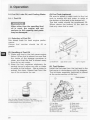
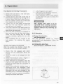
(3) Fuel Tank (optional)
Be sure to attach a drain cock to the fuel
tank to enable dirt and water to settle at
the bottom of the tank to be drained off.
The fuel outlet should be positioned 2030mm above the bottom of the tank so
that only c lean fuel is used.
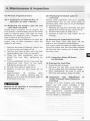
(1) Selection of Fuel Oil
Use diesel fuels for best engine performance.
Cetane fuel number should be 45 or
greater.
(2) Handling of Fuel Oil
1) Water and dust in the fuel cause engine
failure. When fuel is stored, be sure that
the inside of the storage container is
clean, and that the fuel is stored away
from dirt or rain water.
2) Keep the fuel container stationery for
several hours to allow any dirt or water
to settle to the bottom. Use a pump to
extract the clear, filtered fuel from the
top of the container for use.
(j) Sediment
@®Drain cock
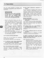
(4) Fuel System
Install the fuel pipe from the fuel tank to the
fuel pump in accordance with the diagram.
The oil/water separator (optional) is placed
at the centre section of the line.
CD
Use the clear filtered fuel from the upper
middle section of the container only, leaving any
contaminated fuel at the bottom.
20
@ To engine
(j) Fuel filter
@ Fuel feed pump
(priming lever)
®Oil/Water separator
® Approx. 25 mm
® Within 500 mm
Fuel system
®
@Drain cock
Q) Fuel cock
®Fuel return
®To fuel injection
pump
@)Fuel tank
1
3. Operation
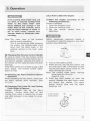
3.1.2 Lube Oil
Air temperature
Single grade
Multi grade
'C
1'
Using other than the specified
lube oil will lead to seizure of
parts, abnormal wear, and shorten
engine life.
(1) Selection of Engine Lube Oil
Use the following lube oil:
• API Classification ............................. CD
• SAE Viscosity ....... ...................... 15W40
(2) Selection of Oil for Marine Gear
• SAE Viscosity ..................... ............... 30
-40"
~4l'l
;;·~ 67'
(3) The Sail Drive attached to
2GM20(F)(C) and 3GM30(F)(C)
• SAE Viscosity ...................90 or 80W90
(4) Handling the Lube Oil
1) When handling and storing lube oil, be
careful not to allow dust and water to
enter the lube oil. Clean around the
filter port before refilling.
2) Do not mix lube oils of different types
or brands. Mixing may cause the
chemical characteristics of the lube oil
to change and lubricating performance
to drop, reducing the engine's life.
Before supplying lube oil to the engine
and marine gear for the first time,
extract all the lube oil already in the
tank. Use new lube oil.
3) Lube oil supplied to the engine will
undergo natural degeneration with time
even when the engine Is not used.
Lube o il should be replaced at the
specified
intervals,
regardless
of
whether the engine is being used or
not.
If you operate your equipment at temperatures
below the limits shown, consult your dealer for
special lubricants and starting aids.
3.1.3 Cooling Water (For Fresh Water
Cooling Type only)
It is Important to check the cooling water
daily. Be sure to use clean soft water (tap
water) for cooling fresh water.
Be sure to add antirust or antifreeze to cooling fresh water.
In cold seasons, the antifreeze is
especially important.
Without antirust, cooling performance will drop due to scale and
rust in the cooling water system.
Without antifreeze, cooling water
will freeze and expand, breaking
various parts.
For your reference, antifreeze
mixed with antirust is now available in the market.
21
m
3. Operation
I
Handling of Cooling Water
1. Choose antirust which will not have any
adverse effects on the materials (cast
iron, aluminum, copper, etc.) of the
engine's fresh water cooling system.
2. Use the proper mixing ratio of antirust
to fresh water strictly as instructed by
the antirust maker.
3. Replace the cooling water periodically,
according to the maintenance schedule
given in this operation manual.
4. Remove the scale from the cooling
water system periodically, according to
the instructions in this operation
manual.
5. Use the proper mixing ratio of
antifreeze to fresh water strictly, as
instructed by the antifreeze maker. If
too much antifreeze is used, the cooling
performance of the cooling water will
drop and the engine may become
overheated.
6. Do not mix different brands of antirust
or antifreeze.
Chemical reactions may make the
antifreeze or antirust useless and
engine trouble could result.
1'.
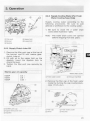
3.2. 1 Supply Fuel Oil
Using gasoline, etc. may
cause a fire.
To avoid mistakes, be
sure to double-check the
kind of fuel before inserting. Wipe off any spilled
fuel carefully.
1. Before filling with fuel, wash out the fuel
tank and fuel system with clean
kerosene or light oil.
2. Fill the tank wit h clean fuel oil free of
dirt and water.
3.2.2 Supply Engine Lube Oil
1 . Remove the filler port cap (yellow) at
the top of the bonnet, and fill with
engine oil.
2. Fill with oil to the upper limit on the
dipstick. Insert the dipstick fully to
check the level.
3. Tighten the filler port cap securely by
hand.
. -::a I
Excessive use of antifreeze also
lowers the cooling efficiency of
the engine. Be sure to use the
mixing ratios specified by the
antifreeze maker for your temperature range.
3.2 Before Initial Operation
Engine Oil Capacity (Oil Pan)
I
2GM20(F)M(C) Full:2.0 I I Effective:1.3 1
3GM30(F)M(C) Full:2.6 I I Effective:1.6 1
Perform the following before using the
engine for the first time:
J
Do not overfill.
Overfilling will cause oil to be
sprayed out from breather and
lead to engine problems.
22
3. Operation
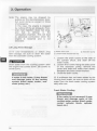
3.2.4 Supply Cooling Water (For Fresh
Water Cooling Type Only)
Supply cooling water according to the
following procedures. Be sure to add
antirust or ant ifreeze to the cooling water.
I
1. Be sure to close the 3 water d rain
cocks (See illustration right).
Note: The water drain cocks are opened
before shipping from the plant.
<D Filler port
@ Upper limit
@ Lower limit
® Bonnet
® Dipstick
3.2.3 Supply C lutc h Lube Oil
1. Remove the filler port cap at the top of
the bonnet, and fill with marine gearclutch- lube oil.
2. Fill with all to the upper limit on the
dlpstick. Insert the dipstick fully to
check the level.
3. Tighten the filler port cap securely by
hand .
,~
M arine gear oil capacity
KM2P
KM3V
KM3P
0.3 I
0.8 I
0.35
<D Oil filler port cap
G) Upper lim1Vlower limit
@Dipstick
--:::::::~~~-<D Fresh water cooler
I
.
I
Water drain co~
G) Exhaust manifold
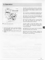
2. Remove the filler cap of the fresh water
cooler by turning the cap counterclockwise 1/3 of a turn.
<D Filler cap
@Dents
Ci) Fresh water cooler
@ Notches
23
3. Operation
3. Pour cooling water slowly into the fresh
water tank so that air bubbles do not
develop. Supply until the water overflows from the filler port.
<D
Fresh water cooling capacity
2GM20F M(C)
3GM30F M(C)
A
DANGER
2.9 I
3.4 I
-----
If the filler cap is
loose, hot steam and
water will spout out
which may cause
burns.
4. After supplying cooling water, replace
filler cap and tighten it firmly. Failure to
do so will cause water leakage. To
replace the cap, align the detents on
the bottom of the cap with the notches
on the filler port and turn clockwise 1/3
of a turn.
5. Remove the subtank cap and fill with
water to the lower limit.
Replace cap.
Subtank capacity: 0.8 I
<D To fresh water cooter
® Upper limit
®Lower hm1t
@Cap
3.2.5 Cranking
When the engine has not been used for a
long period of time. lube oil will not be
distributed to all of the operating parts.
Using the engine in this condition will lead
to seizure.
After a long period of disuse, distribute
lube oil to each part by cranking . Perform
in
accordance
with
the following
procedures
before beginning operation.
1. Open Kingston cock.
2. Open fuel tank cock.
3. Put remote control lever in NEUTRAL.
6. Check the rubber hose connecting the
subtank to the fresh water cooler. Be
sure the hose is securely connected
and there is no looseness or damage.
When the hose is not watertight, an
excessive amount of cooling water will
be used.
(i) Forward
®Neutral
@ Reverse
Manual Operation (Seawater Cooling
only)
4. Pull out decompression lever.
5. Put starting handle on the starting
shaft, and turn about 10 times. Check
for abnormal noise while cranking.
24
3. Operation
3.2.6 Check and Resupply Lube Oil and
Cooling Water
<D
(j) Decomp. lever
® Decomp. lever
@ Drive
@ Compression
-
When engine oil. clutch oil, or cooling
water is supplied for the first time or when
they must be replaced, conduct a trial
operation of the engine for about 5
minutes and check the quantity of lube oil
and cooling water. The trial engine
operation will send the lube oil and cooling
water to the parts, so the lube oil and
cooling water levels will drop. Check and
resupply as necessary.
1. Supplying engine lube oil (See 3.2.2)
2. Supplying marine gear lube oil
(See 3.2.3)
3. Supplying cooling water (See 3.2.4)
3.3 Operating your engine
A. WARNING
Manual
start
position
Electric Operation
4. Turn on battery switch and Insert key
into key switch. Turn the key to the ON
position.
5. Pul the stop knob continuously while
cranking.
6. When the start button is pushed, the
engine will begin cranking. Continue
cranking for about 5 seconds, and
check for abnormal noise during that
time. (If you remove your hand from the
stop knob while cranking, the engine
will start. Pull continuously.)
To prevent exhaust gas poisoning, ensure
good ventilation during operation. Install
ventilation windows, ports or ventilators in
the engine room.
Never touch or allow your clothes to touch
the moving parts of the engine during
operation. If the front drive shaft, V-belt,
propeller shaft, etc. catches your body or
clothes, serious injury may result. Check
that no tools, cloth, etc. are left on or
around the engine.
A
CAUTION
The engine Is very hot during operation
and immediately after stopping, especially
the exhaust manifold and the exhaust
pipe. Avoid burns! Never touch or allow
your clothes to touch any part of the
engine.
25
3. Operation
3.3.1 Inspection Before Starting
Before starting the engine, make it a daily
rule to conduct the following inspections:
(1) Visual Checks
Check for the following:
1. Lube oil leakage from the engine
2. Fuel oil leakage from the fuel system
3. Water leakage from the cooling water
system
4. Damage to parts
5. Loosening or loss of bolts
If any problem Is found, do not o perate the
engine before completing repairs.
(2) Chec king and Resupplying Fuel Oil
Check the fuel level inside the fuel tank
and supply with the recommended fuel, if
necessary. (See 3.2.1)
(3) Checking and Resupplying Engine
Lube Oil
1. Check the engine oil level with the oil
dipstick.
2. If the oil level is low, supply with the
recommended lube oil using the filler
port. Supply oil up to the top mark on
the oil dipstick. (See 3.2.2)
(4) Checking and Resupplying Clutch
Lube Oil
1. Check the clutch oil level with the oil
dipstick.
2. If the oil level is low, supply with the
recommended lube oil using the f iller
port. Supply oil up to the top mark on
the oil dipstick. (See 3.2.3)
(5) Checking and Resupplying Fresh
Water (For Fresh Water Cooling
System)
Check the fresh water level before
operation while the engine is cold.
Checking the water level while the engine
is hot is dangerous, and the cooling water
reading will be misleading due to thermal
expansion.
26
Check and sup ply cooling water routinely
at the subtank only.
Do not remove the filler cap of the fresh
water tank during usual operat ion.
A
DANGER
Do not open the filler cap during operation
or immediately after stopping t he engine.
Hot steam and water will spout out. To
remove the cap, wait until the engine has
cooled down, wrap the cap with a cloth
and loosen the cap slowly. After checking,
replace the cap and tighten firmly.
1. Check that the cooling fresh water level
is above the lower limit on the side of
the subtank.
2. If the water level is close to the lower
limit, remove the subtank cap and
supply fresh water.
3. When the water In the subtank runs out,
remove the filler cap of the fresh water
cooler and supply water until it overflows from the filler port. (See 3.2.4)
3. Operation
3.3.2 How to Start the Engine
If the cooling fresh water runs out
too often, or only the cooling fresh
water in the fresh water tank
drops without any change in the
water level of the subtank, there
may be some leakage of water or
air. In such cases, consult your
Yanmar dealer or distributor without delay.
(1) Start the engine according to the
following procedures:
Electric Operation
1. Open the Kingston cock.
2. Open the fuel tank cock.
3. Set the remote control lever in
NEUTRAL.
Note: The water rises in the subtank
during engine operation.
This is not abnormal. After stopping
the engine, the cooling water cools
down and the extra water in the
subtank returns to the fresh water
tank.
Safety equipment (optional) makes it
impossible to start the engine in any other
position than NEUTRAL.
(6) Checking the Remote Control Handle
Be sure to check that the remote control
handle lever moves smoothly before use. If
it is hard to operate, lubricate the joints of
the remote control cable and also the lever
bearings.
If the lever comes out or there is play in the
lever, adjust the remote control cable.
(See 4.3.4 (3))
(7) Checking the Alarm Devices Electric
Operation
When operating the key switch, check that
the alarm devices work normally. (See
2.5.1 (3))
(8) Preparing Fuel, Lube Oil, and Cooling
Fresh Water in Reserve
Prepare sufficient fuel for the day's
operation. Always store lube oil and
cooling fresh water in reserve (for at least
one refill) onboard, to be ready for emergencies.
4. Turn on the battery switch.
5. Insert the key into the key switch and
turn the key to ON. If the alarm buzzer
sounds and alarm lamps come on, the
alarm devices are normal.
Note: The cooling water temp. warning
lamp does not come on.
(See 2.5.1.{3))
6. Push the start button to start the
engine. Release the start button when
the engine has started. The alarm
buzzer should stop and the alarm
lamps go out.
<D
~ ,®
(!) OFF poSitiOn
® ON positiOn
JF--..,
,
on
I
I
'
27
3. Operation
Manual Operation (Seawater Cooling
Only)
1. Open the Kingston cock.
2. Open the fuel tank cock.
3. Set the remote control lever in
NEUTRAL
4. Pull out the decompression lever.
5. Put the starter handle on the starter
shaft, align the groove and pin, and
turn by hand. When you begin turning,
you will hear the sound of fuel being
injected.
6. Turn the handle vigorously. When the
rotation is rapid, return the decompression lever to original position. The
engine starts.
7. Remove the starter handle from the
starter shaft.
M anual
start
position
(2) Restarting After Starting Failure
Before pushing the start button again, be
sure to confirm that the engine has
stopped completely. If the engine is
restarted while the engine still has not
stopped, the pinion gear of the starter
motor will be damaged.
Electric Operation
••
•
Do not hold the start button on for
~~
Q) Decomp. lever
@ Drive
@ Decompression
rl.
::.,;
more than 15 seconds at a time. If
the engine does not start the first
time, wait for about 15 seconds
before trying again. After the
engine has started, do not turn
the key off. (It should remain ON.)
Alarm devices will not work when
the key is OFF.
(3) Air Venting of the Fuel System After
Starting Failure
If the engine only idles and won't start after
several attempts, there may be air in the
fuel system. If air is in the fuel system, fuel
cannot reach the fuel injection pump. Vent
the air in the system according to the
following procedures.
28
3. Operation
Fuel System Air Venting Procedures
1. Check the fuel level in the fuel tank.
Replenish if insufficient.
2. Loosen the air vent bolt at the top of
the oil/ water separator by turning it 2 or
3 times. When fuel which does not contain air bubbles comes out of the bolt
hole, tighten the air vent bolt.
3. Loosen the air vent bolts of the fuel
filter and the fuel injection pump by
turning them 2 or 3 times.
4. Feed fuel with the fuel feed pump by
moving the lever on the left side of the
feed pump up and down.
5. Allow the fuel containing air bubbles to
flow out from the air vent bolt holes.
When the fuel coming out no longer
contains bubbles, tighten the air vent
bolts.
This completes the air venting of the
fuel system. Try starting the engine
aga1n.
(4) After the Engine has Started
After the engine has started , check the
following items at a low engine speed:
•
•
•
Is the Kingston cock open?
Is the inlet of the Kingston cock on
the hull bottom clogged?
Is t he seawater suction hose broken,
or does the hose suck in air due to a
loose joint?
The engine will seize if it is
operated when cooling seawater
discharge is too small or if load is
applied without any warming up
operation.
3.3.3 Operation
(1) Engine Acceleration
and Deceleration
Use the governor handle to control
acceleration and deceleration. Move the
handle slowly.
(2) FORWARD- NEUTRAL
(boat stopped) - REVERSE Clutch
1. Check that the gauges and alarm
devices on the instrument panel are
normal.
2. Check for water or oil leakage from the
eng1ne.
3. Check that exhaust colour, engine vibrations and sound are normal.
4. When there are no problems, keep the
engine at low speed with the boat still
stopped to send lube oil to all parts of
the engine.
5. Check that sufficient cooling water is
discharged from the seawater outlet
pipe. Operation with too small seawater
discharge will burn t he impeller of the
seawater pump. If seawater discharge is
too small, stop the engine immediately.
Identify the cause and repair.
29
~
lilil
3. Operation
Use the clutch handle to change from
FORWARD to NEUTRAL (boat stopped) to
REVERSE.
Shifting the clutch while operating
at high speed or not pushing the
handle fully into position {half
clutch) will resutt in damage to
clutch parts and abnormal wear.
r:r:l
liil
1. Before using the clutch, be sure to
move the governor handle to a low
speed position (1 000 rpm or less). Move
the governor handle to a high speed
position
after
completing
clutch
operation.
2. When changing between FORWARD
and REVERSE, bring the clutch to
NEUTRAL and pause before slowly
shifting to the desired position. Do not
shift abruptly from FORWARD to
REVERSE or vice versa.
3. Move the clutch handle accurately and
fully Into the FORWARD, NEUTRAL,
and REVERSE positions.
3.3.4 Cautions During Operation
Always be on the lookout for problems
during engine operation.
Pay particular attention to the following:
{1) Is sufficient water being discharged
from the seawater outlet pipe?
If the discharge is small, stop the engine
Immediately, identify the cause and repair.
{2) Is t he exhaust c olour normal?
The continuous emission of black exhaust
indicates
engine
overloading.
This
shortens the engine's life and should be
avoided.
30
{3) Are there abnormal vibrations or
noise?
Do not operate at speeds which produce
violent vibrations. Depending on t he hull
st ructure, engine and hull resonance may
suddenly become great at a certain engine
speed range, causing heavy vibrations.
Avoid operation in this speed range. If you
hear any abnormal sounds, stop the
engine and inspect.
Electric Operation
{4) Alarm buzzer sounds during
operation.
if the alarm buzzer sounds during operation, lower the engine speed immediately,
check the warning lamps, and stop the
engine for repairs.
(5) Is there water, oil, or gas leakage, or
are there any loose bolts?
Check the engine room periodically for any
problems.
(6) Is there sufficient fuel oil in the fuel
oil tank?
Replenish fuel oil in advance to avoid
running out of fuel during operatlon.
(7) When operating the engine at low
speed for long period s of time, rac e the
engine once every 2 hours.
Note: Racing the Engine
With the clutch in NEUTRAL, accelerate from the low speed position to
the high speed position and repeat
this process about 5 times. This is
done to clean out carbon from the
cylinders and
the fuel injection
valve.
Neglecting to race the engine will
result in poor exhaust colour and
reduce engine performance.
3. Operation
[ Engine stopping by engine stop cable
Electric Operation
Never turn off the battery switch
or spark the battery cable during
operation. Damage to parts in the
electric system will result.
3.3.5 Stopping the Engine
Stop the engine in accordance with the
following procedures:
1. Put the remote control handle ln
NEUTRAL.
2. Be sure to race the engine before
stopping it. (See 3.3.4 (7))
3. Cool down the engine at low speed
(approximately 1000 rpm) for about 5
minutes.
Engine stop cable
4. Continue to pull out the engine stop
knob (stop lever) until the engine is
completely stopped. If you release the
knob before the engine has completely
stopped, it may restart.
Stopping the engine suddenly
while operating at high speed will
c ause the engine temperature to
rise quickly, causing det erioration
of the oil and stic king of parts.
(i) Decomp. lever
@ Drive
® Decompression
5. Close the fuel tank cock.
6. Close the Kingston cock.
Neglecting to close the Kingston
cock will allow water to leak into
the boat and may cause it to sink.
Be sure to c lose the cock.
31
3. Operation
Note: The engine may be stopped by
pulling out the decompression lever,
but avoid doing so except in times
of emergency.
In this case, the engine is stopped
by cutting off the air pressure. However, fuel injection does not stop,
and fuel ls leftover in the
combustion chamber. This will lead
to abnormal combustion when the
engine is restarted and is not
desirable.
3.4 Long Term Storage
(1) In cold temperatures or before long
term storage, be sure to drain the water
from the seawater cooling system.
A
CAUTION
Drain water from the cooling system after
the engine has cooled down. Be careful to
avoid burns.
I
l
If water is left inside, it may freeze
and damage parts of the cooling
system (fresh water cooler, seawater pump, etc.)
<D Water drain cock
@Seawater pump
@ Loosen bolts and pull out top
1. Loosen the drain cocks at the side of
the cylinder block, and drain off the
water inside.
2. Loosen the 6 bolts fixing the side cover
of the seawater pump, remove the
cover and drain the water from inside.
Retighten the bolts when finished.
3. Close the drain cocks.
(2) If antifreeze has not been added to the
cooling fresh water, be sure to drain off the
water from the fresh water cooling system
daily after use.
Fresh Water Cooling
If the water is not removed, it may
freeze and damage parts of the
cooling water system (fresh water
cooler, cylinder block, cylinder
head, etc.)
32
3. Operation
(3) Carry out the next periodic inspection
before placing the engine in storage. Clean
the outside of the engine wiping off any
dust or oil.
(4) To prevent condensation inside the fuel
tank, either drain off the fuel or fill the tank.
(5) Grease the exposed area and joints of
the remote control cable and the bearings
of the remote control handle.
(6) Cover the intake silencer, exhaust pipe,
etc. with vinyl sheets and seal them to
prevent moisture from entering.
1
.-
Cooling water drain cocks
1. Open the water drain cocks (3 positions
as illustrated) and drain the cooling
water from inside.
2. Close the drain cocks after draining the
water.
(7) Drain bilge in the hull bottom completely. Water may leak into the boat when
it is moored, and whenever possible it
should be landed.
(B) Waterproof the engine room to prevent
rain and seawater from entering.
(9) During long term storage, charge the
battery once a month to compensate for
the battery's self-discharge.
33
4. Maintenance & Inspection
4.1 General Inspection Rules
Conduct Periodic Inspection for Your
Safety.
The functions of engine components will
degenerate and engine performance will
drop according to the use of the engine. If
countermeasures are not taken, you may
encounter unexpected troubles while
cruising at sea. Consumption of fuel or
lube oil may become excessive and
exhaust gas and engine noise may
increase. These all shorten the life of the
engine. Dally and periodic inspection and
servicing increase your safety at sea.
Inspect Before Starting.
Make it a daily rule to inspect before
starting. (See 3.3.1)
Periodic Inspections at Fixed Intervals.
Periodic inspections must be made after
every 50, 150, 300 and 600 hours of use.
Conduct periodic inspections according to
the procedures described in this Operation
Manual.
Use Genuine Parts.
Be sure to use genuine parts for consumable and replacement parts. Use of other
parts will reduce engine performance and
shorten the life of the engine.
r Apply
Consult Your YANMAR Dealer or
Distributor.
Specialized technicians are ready to assist
you with periodic inspections and maintenance. Consult your YANMAR dealer or
distributor in accordance with the service
agreement.
Servicing Tools
Prepare servicing tools onboard to be
ready for inspecting and servicing the
engine and other equipment.
Tightening Torque of Bolts & Nuts
Over-tightening of bolts and nuts causes
them to come off or their threads to be
damaged . Insufficient tightening causes oil
leakage from the installation face or
troubles due to the loosening of bolts.
Bolts and nuts must be tightened to the
appropriate tightenmg torque. Important
parts must be tightened with a torque
wrench to the correct t ightening torque
and in the right order. Consult with your
dealer or distributor if the servicing
requires the removal of such parts.
The standard tightening torque
standard bolts & nuts is listed below.
for
the following tightening torque to bolts having "7" on the head. (JIS strength
classification:
Tighten bolts with no "7" mark to 60% tightening torque.
If the parts to be tightened are made from light alloy aluminum, tighten the bolts to 80%
tightening torque.
Bolt dia.
1n
x
pitch mm
Tightening torque Nm
----------~
34
M6x1.0
11 ± 01
M8x1.25
M10x1.5
26 ± 03
50 ± 05
-~------~
-~
M1 2x1.75
M14x1.5
M16x1 .5
90 ± 10
140 ± 15
230 ± 20
4. Maintenance & Inspection
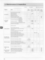
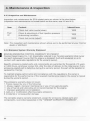
4.2 List of Periodic Inspection Items
Daily and periodic Inspections are
important to keep the engine in its best
condition. The following is a summary of
inspection and
servrc1ng items by
inspection interval. Periodic inspection
intervals should vary depending on the
uses, loads, fuels and lube oils used and
handling conditions, and are hard to
establish definitively. The following should
be treated as a general standard only.
Section 4.3 gives a detailed explanation of
which parts must be inspected and the
procedure for doing so for each interval .
Schedule your own periodic
inspection plan according to the
operational conditions of your
engine and inspect every item.
Neglect of periodic inspection
may lead to engine troubles and
shorten the life of the engine.
Inspection and servicing at 600
hours and thereafter require special knowledge and techniques.
Consult your Yanmar dealer or
distributor.
35
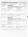
4. Maintenance & Inspection
:::>:Check
System
Itern
hrs or one 150 hrs
month
starting
check the fuel level, and refill
Fuel system·
300 hrs
600 hrs
0
0
I
i
I
- -·
I
.- r-
Crankcase
\0
-
I
- I
-
(first)
•
•
-
<!t
~
• (first)
M anne gear
check the oil pressure warning lamp function
1-
----+seawater outlet
!!_!
)
Replace the lube oil filter
1
(1 yea~ ,
0
)
check the inJection tlmtng
f-check the injectton spray condition
+
Crankcase
check the lube oil level M anne gear
system
Every
) (list)
Aeplace the fuel filler
Replace the lube oil
Evely
)
0 rain the fuel filter
Lubricating
Every
Aller 50
Before
10 rain the fuel tank
e: Consult local dealer
• : Replace
• (first)
!t
) (list)
)
)
During
operatiOn
Cooling system
r
check cooling water level
)
Adjust the tens1on of cooling water pump
driVing belt
f--
:::>-
check the Impeller of the cooling water
p ump (seawater pump)
Every year
Replace the fresh water cooling
check and replace the anticorrosion zinc
----+lean the element of the air Intake silencer
....c
clean the exhausVwater mix1ng elbow
-
Alr intake and
1
, ')
check the exhaust gas condition
check the charge lamp function
f--
C heck the electrolyte level in the battery
During
Iope~t1on
0
I)
') (first)
Adjust the tension of the alternator driv1ng belt
0
0
f--
check the wiring connectors
-----'-
check for leakage of water and oil
(After
lfi:;
e!Jghten all major nuts and bolts
AdJUst mtake/exhaust valve clearance
-----!Remote control
C heck the remote control operation
system, etc.
)
starting)
Cylinder head,
etc.
A dtust the propeller shaft alignment
J
O (list)
O (frsl)
O (frsl)
·' For E PA Requirements , see also 4.4
36
-
0
..)
exhaust system
Eiectrical system
a
•
C lean the breather p1pe
,.
I
l
•
•
•
•
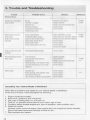
4. Maintenance & Inspection
4.3 Periodic Inspection Items
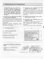
4.3.1 Inspection on Initial 50 Hrs. of
Operation (or after 1 Month)
(1) Replacing the Engine Lube Oil and
Lube Filter (1st time)
During initial operation of the engine, the
oil is quickly contaminated due to the initial
wear of internal parts. The lube oil must
therefore be replaced early. Replace the
lube oil filter at the same time.
It is easiest and most effective to drain the
engine lube oil after operation while the
engine is still warm.
1. Remove the lube oil dipstick. Attach the
oil drain pump and drain off oil.
2. Remove the lube oil filter with the filter
detach/attach tool. \furn to the left.)
3. Clean the filter installation face and
attach the new fllter, tightening by
hand.
4. Turn an additional 3/4 of a turn with the
attachment tool. \furn to the right.
Tightening torque: 20 - 24 Nm)
5. Fill with new lube oil. (See 3.2.2)
6. Perform a trial run and check for oil
leakage.
7. Approximately
10
minutes
after
stopping the engine, remove the oil
dipstick and check the oil level. Add oil
if the level is too low.
.A
CAUTION
Beware of oil splashes if extracting the
lube oil while it is hot.
(2) Replacing the Clutch Lube Oil
(1st time)
During Initial operation, the oil is quickly
contaminated due to the initial wear of
internal parts. The lube oil must therefore
be replaced early.
1. Remove the cap from the filler port and
attach the oil drain pump. Drain off oil.
2. Fill with new lube oil. (See 3.2.3)
3. Perform a trial run and check for oil
leakage.
(3) Draining the (optional) Fuel Tank
Open the drain cock and drain off any
water or dirt collected on the bottom.
Put a pan under the drain to catch the fuel.
Once the water and dirt has been drained
off and the fuel coming out is clear, close
the drain cock.
4.3.2 Inspection Every 50 Hours
(or Monthly)
(1) Draining the Fuel Filter
1. Close the fuel oil cock.
2. Remove the fuel filter cover and drain
off any water and dirt collected inside.
3. After reassembly, be sure to vent air
from the fuel system. (See 3.3.2(3))
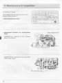
(2) Inspection
and
Adjustment
of
Intake/ Exhaust Valve Clearance
(1st time)
Settling of a new engine and individual
engine use will cause changes in the
intake/exhaust valve and rocker arm
clearance, and adjustment is necessary.
This adjustment requires specialized
knowledge and techniques. Consult your
Yanmar dealer or distributor.
37
I
4. Maintenance & Inspection
{3) Adjusting the Remote Control Cable
The various control levers on the engine
side are connected to the remote control
lever by the remote control cable. The
cable will become stretched and the
attachments loose after long hours of use
causing deviation. It is dangerous to
control operation under these conditions,
and the remote control cable must be
checked and adjusted periodically.
A) Adjusting the Governor Remote Control
Cable
Check to see that t he control lever on the
engine side moves to the high speed bolt
position and low speed bolt position when
the remote control lever is moved to
L(low
speed)
H(high
speed)
and
respectively.
When there is deviation, loosen the
bracket for the remote control cable on the
engine side and adjust.
Adjust the high speed bolt position first
and then adjust the low speed idling.
B) Adjusting the Clutch Remote Control
Cable
Check to see that the control lever moves
to the correct position when the remote
control handle is put in NEUTRAL,
FORWARD, REVERSE.
Use the NEUTRAL position as the standard for adjustment. When there is deviation, loosen the bracket for the remote
control cable on the clutch side and
adjust.
(4) Electric Operation
A
WARNING
Before inspecting the electrical system,
be sure either to turn off the battery
switch or to disconnect the (-) terminal
of the earth cable. Otherwise, a shortcircuit could cause a fire.
Ensure good ventilation when charging
the battery. The use of open flames is
strictly prohibited. Hydrogen gas may
also catch fire.
38
Battery fluid is diluted sulfuric acid. It
can blind you or burn your eyes or skin.
Wear goggles and gloves when handling
battery fluid. Should the fluid be
deposited on your skin, wash with a
large quantity of fresh water and seek
treatment from a doctor.
1) If operation continues with insufficient
battery fluid, the battery will be destroyed.
Check the fluid level periodically. If the
level is lower than specified, resupply
battery fluid (available in the market) up to
the upper limit of the battery.
(Battery fluid tends to evaporate in high
temperatures, especially in summer. In
such cases, inspect the battery earlier than
specified.)
2) If the engine speed will not rise and the
engine cannot be started, measure the
specific gravity with a pycnometre (available in the market).
The specific gravity of the fluid when fully
charged is over 1.27(at 20°C).
Fluid with a specific gravity of below 1.24
needs charging. If the specific gravity
cannot be raised by charging, the battery
must be replaced.
1 ~1
The capacities of the standard
alternator and the recommended
battery assume only the power
necessary for regular operation.
If the power is also used for
inboard lighting or other purposes, the generating and charging
capacities may be insufficient. In
such cases, consult your Yanmar
dealer or distributor.
4. Maintenance & Inspection
4.3.3 Inspection Every 150 hours.
Replace the engine oil and the clutch lube
Oil.
After the second oil change, the engine oil
should be replaced after every 150 hours.
4.3.4 Inspection Every 300 Hrs.
(1) Replacing the Fuel Filter
When there is dirt in the fuel, the filter becomes clogged, and the fuel will not flow
easily. Check and replace the inside
element.
1. Close the fuel cock.
2. Remove the filter case by loosening the
retainer ring (turn to the left) with the
filter wrench.
3. Pull the element out from the bottom,
and replace with a new one.
4. Clean the inside of the case thoroughly,
put on the 0-ring, and close with the
retainer ring. (Turn to the right.
Tightening torque: 12 Nm)
5. Air will enter into the fuel system when
the filter is disassembled, and should
be vented. (See 3.3.2(3)}
(2) Adj usting the Tension of the Cooling
Water Pump Driving Belt.
When there is not enough tension in the Vbelt, it will slip and the cooling water pump
will fail to supply cooling water. Engine
over-heating and seizure will result.
When there is too much tension in the Vbelt, the belt will become damaged more
quickly and the bearing of the cooling
water pump may be damaged.
1. Check the tension of the V-belt by
pressing down on the middle of the belt
with your finger.
With proper flexion, the V-belt should
sink 8 - 1Omm.
2. Loosen the set bolt and move the
cooling water pump to adjust V-belt
tension.
3. Be careful not to get any oil on the Vbelt. Oil on the belt causes slipping and
stretching. Replace the belt if it is marred.
(3) Adjusting the Tension of the Alternator Driving Belt.
When there is not enough tension in the Vbelt, the alternator will not turn and power
will not be generated.
When there is too much tension in the Vbelt, the belt will become damaged more
quickly, and the alternator bearing may be
damaged.
1. Check the tension of the V-belt by
pressing down on the middle of the belt
with your finger.
With proper flexion, the V-belt should
sink 8- 1Omm.
2. Loosen the set bolt and move the
alternator to adjust V-belt tension.
3. Be careful not to get any oil on the Vbelt. Oil on the belt causes slipping and
stretching. Replace the belt if it is
marred.
39
I
4. Maintenance & Inspection
(4) Inspecting and Replacing
Anticorrosion Zinc
The timing for replacing anticorrosion zinc
varies depending on the characteristics of
the seawater and operational conditions.
Inspect the zinc periodically and remove
any corroded areas.
Replace the anticorrosion zinc when it has
been reduced to less than 1/2 of its
original size. If replacement of zinc is
neglected and operation is continued with
a small volume of anticorrosion zinc,
corrosion of the seawater cooling system
will occur and water leakage or parts
breakage will result. The anticorrosion zinc
is on the inside of the anticorrosion zinc
plug which is labeled with a sticker
reading: Anticorrosion Zinc.
(5) Replacing the Engine Oil and Lube
Oil Filter
(See 4.3.1 (1))
(6) Cleaning the Intake Silencer
Disassemble the intake silencer and clean
the inside thoroughly.
Remove the cover by taking off the clamp.
Clean the element with a neutral detergent.
Reassemble after it is completely dry.
4.3.5 Inspection Every 600 Hrs.
(1) Replacing Fresh Water Cooling
Cooling performance drops when cooling
water is contaminated with rust and scale.
Even if antifreeze or antirust is added , the
cooling
water
must
be
replaced
periodically because the properties of the
agent will degenerate.
To extract the cooling water, open the
cooling water cocks (three places) as
shown in 3.4(2).
(Refer to 3.2.4 for resupplying cooling
water.)
40
(2) Inspecting Inner Parts of the Seawater Pump
Depending on the use, the inside parts of
the seawater pump deteriorate and discharge performance drops. At the
specified interval or when the volume of
seawater discharged is reduced, inspect
the seawater pump in accordance with the
following procedures:
1 . Loosen the side cover set bolts and
remove the side cover.
2. Illuminate the inside of the seawater
pump with a flashlight and inspect.
3. If any of the following problems is
found, disassembly and maintenance
are necessary:
a) Impeller blades are cracked or nicked.
Edges or surfaces of the blades are marred
or scratched.
Note: The impeller must be replaced
periodically (every 1000 hrs.).
b) Wear plate is damaged.
4. If no damage is found when inspecting
the inside of t he pump, reassemble the
side cover.
Fit the 0-ring to the groove of the joint
face before replacing the side cover.
If a large amount of water leaks
continuously from the water drain pipe
beneath the seawater pump during
operation, disassembly and maintenance (replacement of the oil seal) are
necessary.
When disassembly and maintehance of
the seawater pump are necessary, consult your Yanmar dealer or d istributor.
• t11 r...:;
The seawater pump turns in the
counterclockwise direction, but
the impeller must be installed by
turning in the clockwise direction.
If the impeller has been removed
for any reason and must be
4. Maintenance & Inspection
reassembled, be very careful not
to make a mistake and turn it in
the wrong direction. Additionally,
if the engine is being turned
manually, be careful to turn it in
the correct direction. Incorrect
turning will twist the impeller and
damage it.
(3) Inspection and Adjustment of Intake/
Exhaust Valve Clearance.
When operating for long periods of time,
the clearance between the intake/exhaust
valve and the rocker arm will change and
affect operation performance. Adjustment
Is necessary.
Adjustment requires specialized knowledge and techniques. Consult your Vanmar dealer or distributor.
(4) Inspecting and Adjusting the Fuel
Injection Spray Condition.
Adjustment is necessary to obtain the
optimal fuel injection to ensure the best
possible engine performance. This inspection requires specialized knowledge and
techniques. Consult your Yanmar dealer or
distributor.
(5) Adjusting the Remote Control Cable
(See page 38, 4.3.2(3))
(6) Inspecting and Adjusting the Fuel
Injection Timing
Fuel injection timing must be adjusted to
ensure optimal engine performance.
This maintenance requires specialized
knowledge.
Consult your Yanmar dealer or distributor.
4.4 EPA Requirements
I
65
4.4.1 EPA Certification Plate
IMPORTANT ENG INE INFOR MATI ON
IR IS ENGINE CONfORMS IOUUIODH YHR U.S. EPA
REGULAIIOKS NOHIOAO COM
PRESS ION ICNII IOK EKCINES.
IRIS ~f IS Cflllfl£0 10 OPfUI£ 01 'OS·!O' FUEL
EN IN fiJI T :
A
I
a)2GM20 (F) series
This engine has the following EPA
Certification Plate attached:
£MGIKE M
ODEL
C
J
[XISS ICMCO~IIOL ST IU ' I
FIH lAIE I D IU !.12.( I[ E IIY/If J IPM
lEfEI Cn£1' SXAH'JAL FOl XAIIIUJJCE
~
SHCIFICAIIOSS I.HD AOJUSII[kiS
• EPA Certification Plate
YANMAR DIESEL ENGINE Co .. ltd.
• Attachment Position for Certification
Plate
• 2GM20 (C) (V), 2GM20F (C) (V)
series.
attached to the intake air
silencer side of the bonnet
EPA certification plate
41
I
4. Maintenance & Inspection
b) 3GM30 (F) series
IMPORT ANl
This engine has the following EPA Certification Plate attached:
UIS fNG IN! mfOINS 1~ [ G'
NON!Ok~ COP,l£SSIOX IGH1110N
IS "'F:'~~!;'-'-';;';~;;;; ::-'-'--*'~~~7"1
ENGINE
IN FORMATION
lEAR US.[PA tfGUIAIIOMS
• EPA Certification Plate
tfffi 01NFI S FANUAl FO! i!INilHANC£ SP£C IFICATIOHS AND
YANMAR DI[SEl ENGIN£ Co
• Attachment Position for Certification
Plate
3GM30(C)(V): attached to the exhaust
side of the bonnet
3GM30F(C)(V): attached to the top of the
fresh water cooler
EPA certification
42
.Lid ~
4. Maintenance & Inspection
4.4.2 Conditions to Insure Compliance
with Emission Standards
• Do not remove the seals limiting the
amount of fuel injected and the speed.
This product is an EPA approved engine.
The following are the conditions that must
be met in order to insure that the emission
during operation meets the EPA standards.
Be sure to follow these.
• Be sure to carry out inspections.
Follow the basic guidelines outlined in
4.3 (Periodic Inspection Items) of this
manual and keep a record of the results.
Pay particular attention to these
important po1nts. replacing the lube oil ,
lube oil lilter, the fuel filter and cleaning
the intake silencer element.
Note: Inspections are divided into two
sections in accordance wtth whom ts in
charge of carrying out the inspection:
(the User) and (the Maker).
• The surrounding conditions s hould be
as follows:
a) Ambient temperature: -20 - 40°C
b) Relative humidity: 80% or lower
c) Permissable value for intake negative
pressure: 0.5kPa (50mmAq) or lower
d) Permissable value for exhaust back
pressure: 6.9kPa (700mmAq) or lower
• The fuel and lube oil used should be
as follows:
a) Fuel: The diesel gas oil ISO 8217
DMA, BS 2869 A 1 or A2 (Cetane No.
45 minimally.)
b) Lube oil: Type API , class CD
Name of parts
• Warranty period for emission parts
If the schedule of periodic maintenance
outlined in 4.4.3 (Inspection and Maintenance) is followed, the warranty period is
determined by the age of the engine or
the number of hours of operation as
indicated below:
Warranty period
(hours of operation/age, whichever
occurs first)
----
< 19kW
19<kW<37
1500 I 2
3000 / 5
Fuel injection pump assembly
1-
Fuel injection valve assembly
43
~
li
I
4. Maintenance & Inspection
4.4.3 Inspection and Maintenance
Inspection and maintenance for EPA related parts are shown in the chart below.
(Inspection and maintenance not noted below are the same, see 4.2 and 4.3)
Item
Fuel
oil
Content
Interval term
Check fuel valve nozzle (clean)
1000
Check & adjustment of fuel injection pressure
& atomizing condition
1000
Check fuel pump (adjust)
2000
Note: The inspection and maintenance shown above are to be performed at your Yanmar
dealer or distributor
4.4.4 Emission System Warranty Statement
EPNUSA EMISSIONS CONTROL WARRANTY STATEMENT
Yanmar Diesel Engine Co., Ltd. (Hereinafter referred to as Yanmar) warrants initial owner
and each subsequent owner that the engine is designed , built and equipped so as to
conform with applicable regulations for its warranty period.
Specific emissions-related parts and components are warranted for the period of 5 years
or 3,000 hours, whichever comes first, after the date of delivery to the initial owner. If any
emissions-related part is defective during the warranty period, the part will be repaired or
replaced by Yanmar.
To maintain engine performance and compliance with the regulations, the owner is
responsible for the performance of the required maintenance listed in the owner's manual
during the warranty period.
This emissions warranty does not cover:
1. Failure caused by any of the following:
• Abuse, neglect, improper maintenance or use of non-genuine parts.
• Use of fuel oil and lubricating oil not recommended for t he engine.
• Improper application and installation.
2. Add-on or modification affecting engine emissions.
3. Incidental or consequential damage.
The complete engine warranty statement, except for emissions-related parts and
components, is provided separately in t he "YANMAR WARRANTY HANDBOOK".
44
5. Trouble and Troubleshooting
Trouble
Alarm Buzzer and Alarm
Lamps On During
Opera lion
Probable Cause
Measure
R eference
"l•ffil r-l.':l
Shift to low speed operation immediately, and check which lamp has come on. Stop
the engine for inspection. If no abnormality is identified and there is no problem with
operation, return to port at your lowest speed and request repairs.
Eng.Lube Oil Press.
Engine Lube Oil insufficient:
Check Lube Oil level.
Warning Lamp goes on
Fuel filter clogged.
Replenish or replace.
·water proof warning lamp
Breakage of seal mount on the sail
Check and change the rubber
goes on
drive.
mount.
C.W.Temp.(Fresh Water)
Insufficient water In fresh water cooler
Check cooling water and replenish.
warning lamp goes on
Insufficient seawater causing temp. to
Check seawater system.
rise.
Ask for repairs.
3.2.2
4.3.1(1)
3.2.4
Contamination Inside cooling system.
Faulty Warning Devices
,,, el
E
~
Do not operate the engine if alarm devices are not repaired.
Serious accidents may result if difficulties are not spotted due to faulty ala rm lamps.
When switch is turned ON:
Alarm buzzer does not sound. Circuit broken or buzzer defective. Ask for repairs.
Warning lamps do not go
Eng. Lube Oil Press.
on
Seawater.
Ask for repairs.
No current available.
Circuit broken or lamp burnt out.
Sensor switches faulty.
Ask for repairs.
Charge lamp does not go
V·belt Is loose or broken.
Replace V-belt; adjust tension.
out during operation
Bat:lery defective.
Check fluid level, specific gravity;
Alternator power generator failure.
replace.
One of the warn1ng lamps
does not go out
4.3.4(3)
4.3.2(4)
Ask for repairs.
' Note: Other warning lamps do not go on when the switch Is t urned on. They only go on when there is an abnormality.
45
5. Trouble and Troubleshooting
Trouble
Probable Cause
Measure
Reference
Starting Failures
No fuel.
Replenish fuel; vent air
Fuel filter is clogged.
Improper fuel
Replace elemenI
Replace with recommended fuel.
Faulty fuel injection.
Compression leakage from
intake/exhaust valve.
Ask for repairs.
Ask for repairs.
Starter does not tum or
tums slowly
Faulty clutch pos1tion.
Insufficient battery charge.
(Eng1ne can be turned
manually)
Cable terminal contact failure.
Faulty safety sw1tch device.
Faulty starter switch.
Shift to NEUTRAL and start.
Check rlu1d lever; recharge; replace.
Remove rust from terminal; retighten.
Starter turns, but engine
does not start
I
3.3.2(1)
4.3.2{4)
Ask for repairs.
Ask for repairs.
Power lacking due to other use.
Ask for repairs.
Consult your dealer.
Internal parts seized; broken.
Ask for repairs.
Abnormal Exhaust Colour
Load 1ncreased
Black smoke
Contaminated 1ntake silencer
Improper fuel.
Faulty spraying ot fuel Injection valve.
Inspect propeller
Clean element.
Replace with recommended fuel.
Ask for repairs.
Incorrect intake/exhaust valve head
Ask for repairs.
Eng1ne cannot be turned
3.3.2(3)
4.3.4(1)
manually
4.3.4(6)
3.1.1
clearance.
Wh1te smoke
Improper fuel.
Faulty spraying of fuellnjeclion valve.
Fuel injection timing off.
Lube oil bums; excessiVe consumption.
Ask for repairs.
Ask tor repairs.
Ask for repairs.
3.1.1
Ask for repa1rs.
Consulting Your Yanmar Dealer or Distributor
Refer difficult problems and repairs to your Yanmar dealer or distributor.
At the time of trouble, check and report the following:
1.
2.
3.
4.
5.
6.
Engine model and number:
Boat name, material of hull, size (tons):
Use, type of fishing done, no. of hours run:
Total no. of operation hours (refer to hour metre), age of boat:
Condition before trouble (engine rpm, type of operation, load condition, etc.):
Details of trouble:
(exhaust colour; sound of engine; does engine start; can engine be turned manually;
type of fuel used; brand and viscosity of lube oil; etc.)
7. Past problems and repairs:
46
5. Trouble and Troubleshooting
WARRANTY SERVICE
Owner Satisfaction
Your satisfaction and goodwill are
important to us and to your dealer.
Normally any problems concerning the
product will be handled by our dealer's
service department. If you have a warranty
problem that has not been handled to your
satisfaction, we suggest you take the
following action:
•
Discuss your problem with a member of
the dealership management.
Complaints can often quickly be
resolved at this level. If the problem has
already been reviewed with the Service
Manager, contact the owner of the
dealership or the General Manager.
•
If your problem still has not been
resolved to your satisfaction, contact
local
Yanmar
Subsidiary
your
Company. (See the back of this manual
for addresses)
We will need the following information in
order to assist you:
•
•
•
•
•
Your name, address and telephone
number
Product model and serial number
Purchase date
Dealer's name and address
Nature of the problem
After reviewing all the facts involved, you
will be advised of what action can be
undertaken . Please remember that your
problem will most likely be resolved at the
dealership, using the dealer's facilities,
equipment and personnel. It is therefore
very important that your initial contact be
with the dealer.
47
I
6. Piping diagrams
(See appendix A at the back of this book)
NOTATION
Fuel oil pipe
- ·-
Lubricating oil pipe
-··-
Cooling water pipe
-:111:11 • 1111:.
Drilled hole
,,
Screw Joint
{Rectangular)
Screw Joint (Union}
--c=r-
Rubber Joint
~
Cock
STP
Steel pipe
RH
Rubber hose
VH
Vinyl prpe
11-1 2GM20
1 Cooling water drain
2 Fuel Injection valve
3 Fuel oil return pipe
4 To main beanng
5 To main bearing
6 To valve rocker arm
7 Exhaust gas and cooling water
8 Mixing elbow
9 Fuel inlet
10 Fuel feed pump
11 Fuel filter
12 Lubricating oil filter (inlet side}
13 Fuel Injection pump
14 Lubricating oil pump
15 Cooling water pump
16 Kingston cock
17 Lubricating oil pressure adjusting
valve
18 Lubricating oil filter (outlet side)
19 Oil pressure switch
20 Thermostat
21 Water temperature switch
11-2 3GM30
1 Cylinder block drain
2 Fuel injection valve
3 Fuel oil return pipe
4 To main bearing
5 Exhaust gas and cooling water
6 Mixing elbow
7 Exhaust manifold drain
8 Fuel Inlet
9 To camshaft bearing
10 Fuel feed pump
11 Fuel filter
12 Lubricating orl filter (inlet side)
13 Fuel injection pump
14 Lubricating oil pump
15 Kingston cock
48
16 Cooling water pump
17 Lubricating oil pressure adjusting
valve
18 Lubricating oil filter (outlet side)
19 Oil pressure switch
20 Thermostat
21 Water temperature switch
22 To valve rocker arm
11 -3 2GM20F
1 Fuellnjection valve
2 Fuel oil return pipe
3 Exhaust gas and cooling water
outlet
4 Mixing elbow
5 Heat exchanger
6 Fuel inlet pipe
7 Fuel feed pump
8 Fuel filter
9 Cooling water pump (seawater)
10 Seawater
11 Kingston cock
12 Cooling water pump (fresh water)
13 Thermostat
14 Fuel Injection pump
15 Lubricating oil pump
16 Lubricating oil inlet· filter
17 Lubricating oil pressure adjusting
valve
18 Lubricating oil o utlet filter
19 Lubricaling oil pressure switch
20 To main bearing
21 To valve rocker arm
22 Exhaust manifold
11-4 3GM30F
1 Fuel Injection valve
2 Fuel oil return pipe
3 Exhaust gas and cooling water
outlet
4 Mixing elbow
5 Heat exchanger
6 Fuel inlet pipe
7 Fuel feed pump
8 Fuel filter
9 Cooling water pump (seawater)
10 Seawater
11 Kingston cock
12 Cooling water pump (fresh water)
13 Thermostat
14 Fuelrnjection pump
15 Lubricating oil pump
16 Lubricallng oil inlet filler
17 Lubricating oil pressure
adjustment valve
18 Lubricating oil outlet filter
19 Lubricating oil pressure switch
20 To marn bearing
21 To valve rocker arm
22 Exhaust manifold
11-5 2GM20V
1 Fuel Injection nozzle
2 Fuel return pipe
3 V~drive oil cooler
4 V-drive system (for local
installation)
5 Exh. gas/C.W.
6 Mixing elbow
7 Fuel Inlet
8 Fuel feed pump
9 Fuel filter
10 Lube oil filter inlet side
11 Fuel injection pump
12 Lube oil pump
13 Kingston cock
14 C.W. pump
15 Thermostat
16 Lube oil press. control valve
17 Lube oil filter outlet side
18 Oil press. switch
19 Water temp. swl tcl1
20 Accessories (for local installation)
21 To main bearing
22 To main bearing
23 To valve rocker arm
11-6 3GM30V
1
2
3
4
5
6
7
8
9
10
11
12
13
14
15
16
17
18
19
20
21
22
23
Fuel injection nozzle
Fuel return pipe
V-drive system (for local installation)
V-drive oil cooler
Exh. gas/C.W.
Mixing elbow
Fuel inlet
Fuel feed pump
Fuel filter
Lube oil filter inlet side
Fuel injection pump
Lube oil pump
Kingston cock
C.W. pump
Lube oil press. control valve
Lube oil filter outlet side
Oil press. switch
Thermostat
Water temp. switch
Accessories ((or local installation)
To main bearing
To valve rocker arm
To cam shaft bearing
11-7 2GM20FV
1
2
3
4
5
6
7
8
9
Fuel Injection nozzle
Fuel return pipe
V-drive oil cooler
V-drive system (for local
installation)
Exh. gas!C.W.
Mixing elbow
Heat exchanger
Fuel Inlet pipe
Fuel feed pump
6. Piping diagrams
10 Fuel filter
11 Kingston
12 Seawater
13 C.W. (fresh water) pump
14 C. W. (seawater) pump
15 Thermostat
16 Fuel mjection pump
17 Lube oil pump
18 Lube oil filter Inlet side
19 Lube oil press. control valve
20 Lube ofl filter outlet side
21 Lube oil press. switch
22 Accessories (for local Installation)
23 To main bearing
24 To valve rocker arm
25 Exhaust manifold
11-8 3GM30FV
1
2
3
4
5
6
7
8
9
10
11
12
13
14
15
16
17
18
19
20
21
22
23
24
25
Fuel infection nozzle
Fuel retum pipe
V-drive system (for local installation)
V-drive oil cooler
Exh. gas/C. W.
Mixing elbow
Heal exchanger
Fuel inlet pipe
Fuel feed pipe
Fuel filter
Kingston cock
Seawater
C. W. (fresh water) pump
Thermostat
C.W. (seawater) pump
Fuel injection pump
Lube oil pump
Lube oil filter inlet side
Lube oil press. control valve
Lube oil filter outlet side
Lube oil press. switch
Accessarles (for local Installation)
To main bearing
To valve rocker arm
Exhaust manifold
11-9 2GM20FC
1 Fuel injection valve
2 Fuel oil retum pipe
3 Exhaust gas and cooling water
outlet
4 Mixing elbow
5 Fresh water cooler
6 Fuel inlet
7 Fuel feed pump
8 Fuel filter
9 Cooling water pump (seawater)
10 Seawater
11 From drive
12 Cooling water pump (fresh water)
13 Thermostat
14 Fuel injection pump
15 Lubricating ofl pump
16 Lubricating oil strainer
17 Lubricating oil pressure adjusting
valve
18 Lubricating oil filter
19 Lubricating oil pressure switch
20 To main bearing
21 To valve rocker arm
22 Exhaust manifold
11- 10 2GM 20C
1 Fuel injection valve
2 Fuel oil return pipe
3 Exhaust gas and cooling water
outlet
4 Mixing elbow
5 Fuel inlet pipe
6 Fuel feed pump
7 Fuel filter
8 Lubricating oil s trainer
9 Fuel injection pump
10 Lubricating oil pump
11 Kingston Cock
12 Cooling water pump (seawater)
13 Lubricating oil pressure adjusting
valve
14 Lubricating oil strainer
15 Lubricating o il pressure switch
16 Thermostat
17 Cooling water temperature switch
18 To main bearing
19 To main bearing
20 To valve rocker arm
11-12 3GM 30C
1 Fuel injection valve
2 Fuel oil return pipe
3 Exhaust gas and cooling water
outlet
4 Mixing elbow
5 Fuel Inlet pipe
6 Fuel feed pump
7 Fuel filter
8 Lubricating oil strainer
9 Fuel injection pump
10 Lubricating oil pump
11 Seawater
12 From drive
13 Cooling water pump (seawater)
14 Lubricating oil pressure adjusting
valve
15 Lubricating oil filter
16 Lubricatmg oil pressure switch
I
11-11 3GM30FC
1 Fuel injection valve
2 Fuel oil return pipe
3 Exhaust gas and cooling water
outlet
4 M ixing elbow
5 Fresh water cooler
6 Fuel inlet
7 Fuel feed pump
8 Fuel filter
9 Cooling water pump {seawater)
10 Seawater
11 From d rive
12 Cooling water pump (fresh water)
13 Thermostat
14 Fuel injection pump
15 Lubricating oil pump
16 Lubricating oil strainer
17 Lubricating oil pressure adjusting
valve
18 Lubricating oil filter
19 Lubricating oil pressure switch
20 To main bearing
21 To valve rocker arm
22 Exhaust manifold
49
7. Wiring diagrams
(See appendix B at the back of this book)
12- 1 For the A -type instrument
panel
Colour coding
R
B
w
y
L
G
0
Lg
Lb
Br
p
Gr
PU
OPTION (OLD A PANEL)
Red
Black
White
Yellow
Blue
Green
Orange
Light green
Light blue
Brown
Pink
Grav
Purple
2
1 + 2 1 3 < 2.5 m-+ 20 mrn
1 +2+3<501
(Cross sectional area)
50
,
-+ 40 mm
1 Procured by customer
2 Battery
3 Battery switch
4 Option
5 Neutral switch
6 For 2GM20, 3GM30
7 Fuse
8 Sore
9 Starter
10 Earth bolt
11 Alternator
12 Rubber seal switch
13 Sail-drive only
14 Spare connector
15 Eng oil pressU!e switch
16 C. W. Temp. switch
17 Wire harness
18 Earth
19 Amplifier
20 Sail-drive only
21 Detail of connector (View A-A)
22 Adapter (Wire harness)
23 Sail-dnve
24 Buzzer
25 (Sail-drive only)
26 Rubber seal
27 Oil pressure
28 Cool. Fresh Water Temp.
29 Charge
30 Push button sw1tch
31 Key switch
32 Detail of connector (View B-B)
12-2 For the B-typ e
instrument panel
NEW B PAN EL
1 Procured by c ustomer
2 Battery
3 Battery swrtch
4 Option
5 Neutral switch
6 For 2GM20, 3GM30
7 Fuse
8 Sore
9 Starter
10 Earth bolt
11 Alternator
12 Rubber seal switch
13 Sail-drive only
14 Tache sensor
15 Eng, oil pressure switch
16 Cool. water temp. switch
17 Wire harness
18 Earth
19 Amplifier
20 Sail-drive only
21 Detail of connector (View A-A)
22 Deta1l of connector (View C-C)
23 Starter switch
24 Fuel tank empty
25 Not used
26 Rubber seal
27 Cool. water temp.
28 Engine oil press.
29 Charge
30 Tache with hour meter
31 Buzzer
32 Buzzer stop
33 Illumination
34 Detail of connector (View B-B)
APPENDIX A
Piping diagrams
11 - 1 2GM20
®
c
)
~ I~
X ,
0
.
~
"'
r---··- -020 x 13.5 RH
'y......-...
~
""'
-
' I
' I
¢.:;"1
•'I I
II
II
II
1/
.....
- -®
r
a:
II
I
e~ :
II
II
\
e
e
'I
ll
.
~
r
..,a:
-
o4.76 X 10.7 STP
..,
X
o-
\
A-1
APPENDIX A
Piping diagrams
c )
11-2 3GM30
:c
a:
- .'
"l ' I
(')
X
0
N
<T
@)
920 >< 13.5 RH
Y
~
:>- J>
, .. -~··-c::t--<
....
®
'-.:...
:=--®
...
-
C/)
f X
~
v "\
~ ---- .r
I-
II
I
1\..
!
./
I
'r4o~
.............
.........
·'
'I
I1
/ ..........
::
f
l I
~~
<¢:;iI I
'---1
e
•r·~
,.
t
8
1
I
~~
e
" ' -...__
----1
II
t
0..
.._
'
•~
1-
~~w
l"1
~ fH...._~ ~
I t
CD
gX
II
I
Q..
I
•'
11
<.0
e
It
-<>
I Il Il
,,
¢:
'•
-
' I
',
r
::
1._._ ...._ ,
n
I I
~
II
<¢:~:
~
....
¢:
1If
I
£!:!
X
---''--~....
...
'l ,.-.,....... •
~:
~
II
-,::---:;
I1
IL~~ t
~
~
I I
~ ¢:~ :
~
I'
.L':::~=-===..,.,.=t=i'=~==::;::::=:~:~r--1-~r·:c
t.,~ . ":~
-
~~~ ~
I
-
.<")
e -o---+-'
Q13 xt3 RH
I
A-2
X
~
I I
I I
I
.
(')
- -
I I
1I
I
:c
a:
U'>
lo...~
~
@)
C::>-.
--+- ·-+-
-
<0
....
iJ ~
-<>
®
Piping diagrams
APPENDIX A
11-3 2GM20F
®
+
@~)
:r
CI:o
.,
0
I
~
X
~
-
" - \ ~""
~~-=--=--~·v_...
~
I'.
J:
_I
lr.-.
\
~
-Q
....
,,
11:
It
I
h
'
;i
:r
CI: o0
"'...
CD
•0
,,
ti--......-
11
It
::
",,
II
io-J'-... - ·
~r-
"
II
1
:J
II
~
-
l-i~o
,..-....,if
:
:ve
r-- --
-
<
r>
te
<.•
~
< v ...
~ ~--'
< . . ~13xt3RH - e
<
0.
1-
-
(/)
X
1'----..
II
II
.,
:r
a:
1:1: J !:lo
.--··
I
II
II
It
lo
II
L'
~
t-~
::
:r
a:
\
/ ...
v. =::
e
0
\\
;rii
----f=.l: J; >
-<>o
tf1\
® ~(/)·'rtV
®
.....
s
x
<D
":
<t>
~I,•
~ .....
' JL--)
__,.
L--
8)__....-u---r,,_
<>4.76 X 10.7 STP
~ ~~-------------r
-"'
-"'....
X
e
t
A-3
Piping diagrams
APPENDIX A
11-4 3GM30F
c )
®
----
'
I[
!'---~)
.~
/
,,lo
II
I
I :I
,,
-
:z:
a:
...
<
II
II
I
1 r-""'P
·- -~
I,
lo
...':~a.....
Ii
,,
II
II
II
II
l-.J•---.
r-., r---v
II
II
I•
--'-......../
t>
If)
t>
<
-
0
X
II
II
II
II
II
•
If)
ti
X
'-,-----t----!--,...l~ ~
e
.. :z:=+--- - -- --r""
a:
~
X
-<>• e
(')
A-4
-
e
-
....
X 9L"~
t ...X
e
(/)
d.LS L"OI
:z:
a:
ti
APPENDIX A
Piping diagrams
11-5 2GM20V
:I:
cr
l"l
-
'M
X
0
®
@)
@)
®
~
~
®
'
n
®
@
'
-e
~-:;
-
I
:I:
cr
!3
I
X
-
I
M
I
<>
~.76 X
Io II
10.7 STP-
"""'\
e .--~---o~1~3~x~acR~H--~
-
e
---------,
.___ -- - - -- -+-=-~-...,
_1'1_
'-
/
~
I
if/'I.
I
A-5
Piping diagrams
APPENDIX A
11 -6 3GM30V
@
c
I
)
:I:
,
a:
.~
X
0
~
•
,.------+----!-,-----
- "1..---{'i ~
-
- - 1-
" >---1_;
------------::1 / ' ;:~
r---------- - ..=------}!_/
~,
f
6~
It--'
®-~~~~~
' o.. ~-. ,
"Lr--1
I
I
r-----.....
I ...........
-
11
I
.I
~
~ -~
" :r 1- --•
-
.J.l
/
~a: '-
"I
~
~---
/o..
_/
~I
.... I
®
/
til
II
~---"'"
~~ f ~
-
x
~
..1
tt
v ~,._....,.-=----e
ID
r--:
I\..
_._
:r
/
a:
M
tx
M
~
/
t t
@l::::::::===tJ
--
~
:r
a:
"'
-
e
/
:r
a:
-
(")
M
I
-<>
'\
I
®
X
~
X
M
-<>
<>-
te
8 ----++-7.~1~3~x~a~RmH-~\~
--
-
-- ---'I:-- - - -
L......-1-- -
. . . .___ --:~·:=-----=1.._----,.., . ~
'---
I
e
A-6
e
\. ~ ~""~
1 \
+ -----::-------'
-,___~
. ~... - -e
te
APPENDIX A
Piping diagrams
11-7 2GM20FV
\
I
\.----@
®
-
®®
~\ " " " o24 13.5 RH -'\ ~\
X
"-
\
-
-
..=-
\
.<"
I --
1
' [ lJ'f't·JI:-r
A.
..........
,I
)
'
r
"'\
---_.)
:-.
~~
'
~\
~
,,
''
®
~
trl
rl
I
I
a:
Ill
t 't
9
1r-
,,
'
t
U>
.....
~
11
I
.l_L_-~
_,_
e
t
I
I
~
I
'6
X
t>
I
"'--'
h
013xi3RH
• e
'
1::1:
Q<!,76 x tO.75 STP
\
+j~$:!
X
~
e
te e
\3x:RH
-
1\
e
t>
<t:>
...og .....
e
(J)
I
---
II
f ll
I/
A.
1-
.•
--
~:
.
t>
<r>
@)
'... t~
-v
'-_,)
<
<
Q)
I
I
i
-
-
!- --..;
I>
I
Ill
-
-
/
'
II
®
<>
.'
® I,
It I'I
X
X
,.
/
I
.....
II
1
1
r
'
I
(J)
t:JL- ~
I
-
,, -
e:1t®
-®
"'-
t
/ oJTT}
a:
II
II
~
a:
...,
':I:
II ®
...
pX
:I:
I'\
~
t
II
tl
1
-
~
t-
'8.
I~= ~
II
:I:
l.r
"'X
X
II
---
-
~
I
II
!le
0
a:
~
ll
X
:I:
!f
---F:(1:>
.) ~
I
"'-
@
\.>-1
\
®
Ill
@)
-
--
--
e
\
_....
j
.\;"J
I
I
e
A-7
APPENDIX A
Piping diagrams
11-8 3GM30FV
c )
>----@1---
® ®
®
~\
-\
®"':r ""'\" -\\
®
a:
.....
\
-
\
M
·~
J
J
IX
l£--=y ~~""'
)
"'\
';:
1\. - _/
_it_
1-- 4:1 :0
~~-- -''
\.
.I
I
I
I
,,r-
:r
',,,
a:
t>~
"'
M
,r-
I
t
I
'
I'
---
,._
I
'
a:
i<
-
X
<n
,._
::
ci
X
<>4.76 x !0.7 STP
te
--
\-._
\.
..v.
I , \
J
a:
t>
~
t .:;
.I.
~
...::..
I>
,J
\13:RH
e
:r
/
',
.. -
\
1...
1\.
e
-
e
~
K--/
013 x t3 RH
<.
l.
I
'
-
'
<.
"':
~~--~-
---
,
1-
M
0
.......
t> V'
<.
0..
1-
I
I
e
I
'
"'
,,,, "" .,
t''
l
®
1- ---
<.
I
II
¢, ,
II
1~- ~
~
/
I
'
Jl '
~~
II
-
®
I
@
~
A-8
,,
"'
:I
1-
¢ JI :r
X
II
•
.•
,, I<
,._
2
X
I
9
,,,,
<n
--
<n
'-T"Y
II
1-
0..
1-
I
11
¢:,1
.,<>
0..
1- J!..._ ~
I
"'"'£:!
'k!>
®
lr
"'...
<n
•tl;
)
L
""~
....
X
I L --;>
I
X
..)
K!)
d
a:
--f
0..
1-
,,,
:r
....
~ -
l• Lr -~
",,
0
(&
X
=f:j
'
\1-B
f-.--.
1'
I
®
e
\ -"'F
@)
~
-Y.·o
-
.-\.
®~1x
"'
?""'
-
-
®
r~
!:i
...
e
X
"'<>
e
•
e
APPENDIX A
Piping diagrams
11-9 2GM20FC
J:
a:,
-,
riX
...
+
.... ;
N
J:
-
a:
"'-
M
..;
a..
>(
...
....
M
X
II
I
II
J:
,.
1-
I
+
+ 'I
II
a:•
"'..,X
'
...
ll.
....
M
(/)
t~
"'....
IL _ :>
tr-
II
®
e
...
ll.
-
(/)
II
....
II
X
-;r=~ ~
"
...
ll.
II
II
@)
ci
II
II
I
II
"'-
--
(/)
N
<-i
X
....
<.0
<:;; •
,,
®"
,..., '
II
;13 x3t RH
e
.s
J:
tla:'
I X'
I
~ ~~
,, ...
I
tl '
I
L-.= ~
II
--..
:X:
·-..,
a:
· "'1
; 4.76 x 0.71 ST P
X
...
"'....
J:
0:
-
"'X
M
A-9
APPENDIX A
Piping diagrams
11 -10 2GM 20C
c
r
;)
X I
0
....
@
©
-------,
-
j620
r
---r
•
....
x 3.5t RH
--- ---....,
:I:
a:
.,.,-
til
Q.
II
.....
t~
..;
)(
.......
)(
-""
I I>
II
II
N
0..
.....
)(
•• ....
"'
I I_ __,._
r..,
1
(/)
t --"
....
CD
II
II @ o..
'I
t;
It
;::
-~,= ~ 0
-:I:
-
a:
It
M
II
X
-
I
M
II
I
+4 76 X 0 7t ST?
•
of>13x3tRH
of> 4 5
A-10
APPENDIX A
Piping diagrams
11- 12 3GM30C
@ @
lt- ..........
z:
a:
~ t
....... ,,
0
-..,
~
(0...
X
-
a:
®
,.,
,.,"
'
¢: ~
..
-
t
@
.,.
r:
Ul
X
a: 0
;4,76 x 071 STP
; l3 "31 RH
A-12
,;:::
+·-
-
1--'
-
~~
...
~
N
X
<D
....
..._
~
APPENDIX B
Wiring diagrams
12- 1 For the A-type instrument panel
I
I
,---·
- ·'hI
1
o
8
I '
''
L .·-
-Jo
'!
~
I''
p
0
..-'"~·~
~
!
··-
___ _j'
'
L
8~
'
!I8
®'
'
@
I
~
'
'
'
~tl
~
I
'
I
~
<2(1 ~II
I>
,N 8 '-r·l
j- * r9ii-- i
0 1
'
----I
I@
----- --·-'
I
,-
I
''
---·
-...:::~
I
'
'
18 ~1
'
.J
i-------'
8
;
~
G;BII®
1--1
v
1....
'?• -
"I
I: ~
~* [
I
I
(§) JI
JJ
tl
--
'-·
,,
I
Ii
'
..
· I
I
ll@
I
I'
,.,"
~
l"'
;
l " '--/
I•
l•
1-
j~ ~ ~ ~L.,
I
"j
~
'
;
..
~
"'
~
~ li ...
0
G>
"' "'
~
~
---T·
! '
I) @
'
IG'•"'"' o
I
~
Jr
®
.t
...
"'
0
I
:®
~
~
@ ;;
.s
•/• I
,~-
,.......,
~
® (r- )
~
::
1/0
&I'
....
•o
--
"'
~
¥1•
....
® ® ®®®
- - - - - -----------------------------------------B
--1
-
~
Wiring diagrams
APPENDIX B
12-2 For the B-type instrument panel
Ji®
,.-----------
I
I
I
I
I
8
r------- - T]
~
Ell~~
I 1
I '
-·1
''
yj---
~
+
~
•
''
I
''
I
''
I
I
I
~
~
I"
'
11
1
fSJ.®
I
i8
o:ci'
'8
q'~
I !
L
_j'
' _____
"'
_>;
I
[/
~
~
"1
(§), .....
!
'
!s~* !
I'
I'
I
'
~ -~
I
'
L
I
I
!
,
~~:
.
II L
...
I r=Qill!l l
r~~®
'
'
ll =0111
'I
L __ ___ _j
r-----,
'
tl
~
8~
::
__j'
®®
• -1 l= ::t
@
~
I·
I
I
'
L
'
I
I~
~~:
)+
I
'
.. :
®®!
~
--
__ I
.. "'
': ..
~ .... ..
~
0
~
~
~
~
o
1.
•
::;.
~-
M
r(
~
'-
~
•
---... L--
®
;/
~
:-
•
~
~ 1 ~1~
:e ~
~
®@c::x.er
5
.."'
6
~
...,-
~ ·
:)~)
-
"'
~
u
<
~ro o
.. ,_..o~
~
...
., 0""'
~
8-2
CAUTION: Overcranking engine with
water lift muffler can cause damage I