1
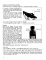
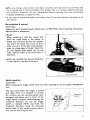
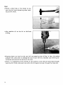
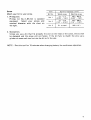
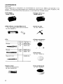
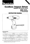
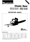
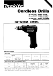
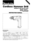
Cordless Driver DriII
MODEL 6012HD
MODEL 6012HDW
With Fast Charger and Carrylng Case
INSTRUCTION MANUAL
S PEClFICAT10NS
Model 6012HD
Steel
Wood
Wood screw
Machine screw
6 5 mm
1114"l
1 5 mm
5 . 1 mm x 55 mm
13/16" x 2-118")
6 mm
1114")
1518")
Battery Cartridge 9 0 0 0
Voltage
9
Nuts
I
:Em)
1
400
' lrloo
1
261 mm
110-114")
1
1.6 kg
13.5 lbsl
Model DC9700 Fast Charger
Input
output
* Manufacturer reserves the right to change specifications without notice
* Note: Specifications may differ from country to country.
Charging time
IMPORTANT
SAFETY INSTRUCTIONS
(For All Tools)
WARNING: WHEN USING ELECTRIC TOOLS, BASIC SAFETY PRECAUTIONS SHOULD ALWAYS BE FOLLOWED TO
REDUCE THE RISK OF FIRE, ELECTRIC SHOCK, AND PERSONAL INJURY, INCLUDING THE FOLLOWING:
READ ALL INSTRUCTIONS.
1. KEEP WORK AREA CLEAN. Cluttered areas and benches invite injuries.
2. CONSIDER WORK AREA ENVIRONMENT. Don't use power tools in damp
or wet locations. Keep work area well lit. Don't expose power tools t o rain.
Don't use tool in presence of flammable liquids or gases.
3. KEEP CHILDREN AWAY. All visitors should be kept away from work area.
Don't let visitors contact tool or extension cord.
4.STORE IDLE TOOLS. When not in use, tools should be stored in dry, and high
or locked-up place - out of reach of children.
5. DON'T FORCE TOOL. It will do the job better and safer at the rate for which
it was intended.
6 . USE RIGHT TOOL. Don't force small tool or attachment t o do the job of a
heavy-duty tool. Don't use tool for purpose not intended.
7 . DRESS PROPERLY. Don't wear loose clothing or jewelry. They can be caught
in moving parts. Rubber gloves and non-skid footwear are recommended
when working outdoors. Wear protective hair covering t o contain long hair.
8. USE SAFETY GLASSES. Also use face or dust mask if cutting operation is
dusty.
9. DON'T ABUSE CORD. Never carry tool by cord or yank it t o disconnect from
receptacle. Keep cord from heat, oil, and sharp edges.
IO. SECURE
WORK. Use clamps or a vise t o hold work. It's safer than using
your hand and it frees both hands t o operate tool.
11. DON'T OVERREACH. Keep proper footing and balance at all times.
12. MAINTAIN TOOLS WITH CARE. Keep tools sharp and clean for better and
safer performance. Follow instructions for lubricating and changing accessories. Inspect tool cords periodically and if damaged, have repaired by authorized service facility. Inspect extension cords periodically and replace if
damaged. Keep handles dry, clean, and free from oil and grease.
2
13. DISCONNECT TOOLS. When not in use, before servicing, and when changing accessories, such as blades, bits, cutters.
14. REMOVE ADJUSTING KEYS AND WRENCHES. Form habit of checking t o
see that keys and adjusting wrenches are removed from tool before turning
it on.
15. AVOID UNINTENTIONAL STARTING. Don't carry plugged-in tool with finger
o n switch. Be sure switch is OFF when plugging in.
16. OUTDOOR USE EXTENSION CORDS. When tool is used outdoors, use only
extension cords intended for use outdoors and so marked.
17. STAY ALERT. Watch what you are doing, use common sense. Don't operate
tool when you are tired.
18. CHECK DAMAGED PARTS. Before further use of the tool, a guard or other
part that is damaged should be carefully checked t o determine that it will
operate properly and perform its intended function. Check for alignment of
moving parts, binding of moving parts, breakage of parts, mounting, and any
other conditions that may affect its operation. A guard or other part that
is damaged should be properly repaired or replaced by an authorized service center unless otherwise indicated elsewhere in this instruction manual.
Have defective switches replaced by authorized service center. Don't use
tool if switch does not turn it on and off.
19. GUARD AGAINST ELECTRIC SHOCK. Prevent body contact with grounded
surfaces. For example; pipes, radiators, ranges, refrigerator enclosures.
20. REPLACEMENT PARTS. When servicing, use only identical replacement parts.
VOLTAGE WARNING: Before connecting the tool t o a power source (receptacle,
outlet, etc.) be sure the voltage supplied is the same as that specified on the
nameplate of the tool. A power source with voltage greater than that specified
for the tool can result in SERIOUS INJURY t o the user - as well as damage t o
the tool. If in doubt, DO NOT PLUG IN THE TOOL. Using a power source with
voltage less than the nameplate rating is harmful t o the motor.
3
1.
SAVE THESE INSTRUCTIONS - This manual
2.
3.
4.
5.
6.
7.
8.
Length of Cord (Feet)
25
50
100
150
AWG Size of Cord
18
18
18
16
9. Do not operate charger w i t h damaged cord or plug - replace them immediately.
10. Do not operate charger if it has received a sharp blow, been dropped, or
otherwise damaged in any way; take it t o a qualified serviceman.
11. Do not disassemble charger or battery cartridge; take it t o a qualified
serviceman when service or repair is required. Incorrect reassembly may result in a risk of electric shock or fire.
12. To reduce risk of electric shock, unplug charger from outlet before attempting any maintenance or cleaning. Turning off controls will not reduce this
risk.
4
ADDITIONAL SAFETY RULES
FOR CHARGER & BATTERY CARTRIDGE
1. Do not charge Battery Cartridge when temperature is BELOW 10°C (5O0F1
or ABOVE 4OoC (104OF).
2. Do not attempt t o use a step-up transformer, an engine generator or DC power
receptacle.
3. Do not allow anything t o cover or clog the charger vents.
4. Always cover the battery terminals w i t h the battery cover when the battery
cartridge is not used.
5. A battery short can cause a large current flow, overheating, possible burns
and even a breakdown.
(1) Do not touch the terminals w i t h any conductive material.
(2) Avoid storing battery cartridge in a container with other metal objects such
as nails, coins, etc.
(3)Do not expose battery cartridge t o water or rain.
6. Do not store the tool and Battery Cartridge in locations where the temperature may reach or exceed 5OoC (122OF).
7. Do not incinerate the Battery Cartridge even if it is severely damaged or is
completely worn out. The battery cartridge can explode in a fire.
ADDITIONAL SAFETY RULES
1. Be aware that this tool is always in an operating condition, because it does
not have t o be plugged into an electrical outlet.
2. Always be sure you have a firm footing.
Be sure no one is below when using the tool in high locations.
3. Hold the tool firmly.
4. Keep hands away from rotating parts.
5. When drilling into walls, floors or wherever "live" electrical wires may be
encountered, DO NOT TOUCH ANY METAL PARTS OF THE TOOL!
Hold the tool only by the insulated grasping surfaces t o prevent electric shock
if you drill into a "live" wire.
6. Do not leave the tool running. Operate the tool only when hand-held.
7. Do not touch the drill bit or the workpiece immediately after operation: they
may be extremely hot and could burn your skin.
SAVE THESE INSTRUCTIONS.
5
Installing or removing battery cartridge
0Always switch off the tool before insertion or removal of the battery cartridge.
0
0
To remove the battery cartridge, pull out
the set plate on the tool and grasp both
sides of the cartridge while withdrawing it
from the barrel.
I
Set plate
To insert the battery cartridge, align the
tongue on the battery cartridge with the
groove in the housing and slip it into
place. Snap the set plate back into place.
Be sure to close the set plate fully before
using the tool.
0
Do not use force when inserting the battery cartridge.
I f the cartridge does not slide in easily, it is not being inserted correctly.
Charging
Plug the fast charger into your power
source. Insert the battery cartridge so that
the plus and minus terminals on the batbutton
tery cartridge are on the same sides as their
respective markings on the fast charger.
Insert the cartridge fully into the port so
that it rests on the charger port floor.
Press the start button (red). The charging
light will come on and charging will begin.
I f the charging light does not come on,
press the reset button (yellow) first, then
the start button (red). I f the charging light
goes out within 10 seconds even after pressing the reset button and start button a couple
of times, the battery cartridge i s dead. (CAUTION: Wait for more than 5 seconds after
the charging light goes out to press the reset button again.) Replace it with a new one.
When the charging light goes out after about one hour, you may remove the fully charged
battery cabridge.
After charging, unplug the charger from the power source.
CAUTION:
.Your new battery cartridge is not charged. You will need to charge it before use.
.Do not keep the button pressed in with tape, etc. or the circuit will not function properly. Also, a malfunction of the charger may result possibly causing overheating, etc.
0
6
I f you try to charge a cartridge from a just-operated tool, sometimes the charging light
will not come on. If this occurs, l e t the cartridge cool off for a while. Then re-insert it
and try to charge it once more.
When you charge a new battery cartridge or a battery cartridge which has not been used
for a long period, it may not accept a full charge. This i s a normal condition and does
not indicate a problem. You can recharge the battery cartridge fully after discharging
it almost completely a couple of times.
0 If you wish to charge two battery cartridges, allow 15 minutes between chargings on the
fast charger.
Bit installation & removal
CAUTION :
Always set the Forward-Reverse switch lever to NEUTRAL when installing, removing or
adjusting bits or accessories.
0
Chuck
When installing a drill bit, notice that
there are three holes in the chuck a t
which you must use the key for tightening. Insert the chuck key in any of the 3
holes and turn to the l e f t (counterclockwise) to release jaws of chuck. Insert the
bit and tighten with chuck key to the
right. Tighten evenly a t all three holes in
sequence.
Tigbtten
.After use, re-attachthe clip-on chuck key
in the hole for it on top of the tool.
/
Clip-on chuck key
Switch operation
CAUTION :
When releasing the trigger, check to be sure that it springs out to i t s original released position.
The tool starts when the trigger is pulled
and stops when it i s released. To reverse
the rotation, use the reversing switch lever
equipped just above and in front of the
trigger switch. However, when changing the
rotational direction, be sure the trigger
switch is released (OFF) and check the
rotational direction. Keep the reversing
switch lever in the neutral position whenever you are not using the tool.
NEUTRAL
Trigger switct
Drill
*Punch a small hole in the metal to prevent the bit from skitterring when starting to drill a hole.
0
Use machine oil on the bit to facilitate
drill ing.
.Pressing down too hard on the tool will not speed up the drilling. In fact, this undue
pressure will only serve t o damage the tip of your drill bit, decrease your drilling performance and shorten the service of the tool.
0There is a tremendous force exerted on the tool/bit a t the time of hole break through.
Grip the drill firmly and exert care when the bit begins to break through the materials.
8
Screw
Match vour bit to vour screw.
Phillips bits
Phillips bit No. 2-65 mm is standard
equipped.
Select your screws and
nominal diameter with the chart on
the right.
Item
I
Bit No.
I
No. 3
I
I
Nominal diameter (mm)
Wood screw
I
I
Machine screw
2.1 - 2.7
M2 - M2.6
3.1 - 4.8
M3 - M5.5
5.1 (13/64")
I
M6 (1/4")
Slotted bits
Unless you use a bit that fits properly the slot on the head of the screw, the slot will
be damaged and the screw will not fasten. If the bit fails to match the slot, use a
grinder or some such tool to trim the bit to fit the slot.
NOTE : Rest the tool for 15 minutes when changing battery for continuous operation.
9
Speed changeover
.To change the speed, turn the speed
change knob 180" while the drill is running. Be sure that the speed change knob
i s turned to the correct speed setting
before you begin operation. See arrow
indication. Use the right speed for the
job.
Fastening torque adjustment
Just turn the fastening torque adjust
knob on the tool in order to select any of
5 different fastening torques. Make sure
that the arrow points to the right torque
before you begin the job. Torques are
numbered from 1 to 5 in the order of
strength. Set to 5 for use as a drill. The
torque setting for number 5 is designed
for drilling, and to protect the motor
from burn out, so it can slip when a very
high torque is applied.
Grip
.The grip shown on the right is recommended. However, grip the tool firmly
with both hands when drilling a largediameter hole.
10
Fastening torque
adjust knob
I
Arrow
*The hole on the heel of the tool is a convenient way to carry it by a cord, hook
or other means.
I
11
ACCESSORIES
CAUTION :
These accessories or attachments are recommended for use with your Makita tool specified in this
manual. The use of any other accessories or attachments might present a risk of injury to persons. The
accessories or attachments should be used only in the proper and intended manner.
0
Fast charger
Model DC9700
0
Makita Battery cartridge 9000 (9.6 V)
1 hour fast charge nickel cadmium battery
Part No. 632007-4
0
Bits
1 I
I
#5F
#7F
Square drill b i t
0
Battery holster
Holds with extra battery
Part No. 823033-3C
12
Charger 1 2 V for car
Model DC9112
0
Chuck key S10
Part No. 763419- 1
0
Rubber pad assembly
Part NO. 123001 - 2
0
Wool bonnet
Part No 743401 -6
I
I
Slotted
0
I
784010-0A
784011-0A
784606-0A
0
Foam polishing pad
Part No. 743023-2
0
Tool holster
has some bits storage space.
Use holster t o carry drill only after
removing bit. Also, keep the reversing
switch lever in neutral position when
carrying in the holster.
Part No. 823033-36
Part No. 823033-3E (Genuine leather)
0
Tool carrying case
Part No. 823085-7 (Steel case)
Part No. 824145-8 (Plastic case)
13
Feb
19
86 EN
CORDLESS DRIVER DRILL
Model 6012HD
Note: The switch and other part configurations
may differ f r o m country to country
14
MODEL 6012HD
Feb-19-86
EDDESCRIPTION
EN
DESCRIPTION
",',;I
MACHINE
______
1
2
3
4
5
6
7
8
9
10
11
12
13
14
15
16
17
18
19
20
21
22
23
24
1
1
1
I
1
1
1
1
1
1
1
1
1
1
1
1
1
1
1
1
1
1
1
1
Pan Head Screw M5x18
Drill Chuck S 1 0
Spindle
Pi" 3
Ball Bearinq 6000LLB
STOPRing E 9
Compresslo" Spr,ng 10
Thin Washer 1 0
Spur Gear 7 8
Ring 16
Spur Gear 9 3
Thin Washer 1 0
Compression Spring 1 0
Flat Washer 5
Plane Bearing 5
Shift Knob Supporler
compress~o" spr ny 3
S ~ e e Ball
l
4 8
Shift Knob
Retaining Ring S 6
Flat Washer 1 4
Ball Bear ng 626LLB
F l a t Washer 6
Spur Gear 8 9
25
26
27
28
29
30
31
32
33
34
35
36
37
38
39
40
41
42
43
44
45
54
55
-
4
1
1
Steel Ball 4 8
Clutch Cam
Conical Compression Spring 1 6 - 2 1
I
08%
1
1
1
1
1
1
Thrust Needle Gauge 1 0 2 3
Flat Washer 8
Slider
P," 3
Gear 1 2 - 2 8
I
1
1
1
1
1
1
1
8
1
1
1
1
Plane Bearing 4
Shifter
Leaf S p m g
Holder 6
DC Motor 9 6 V
Switch
Housing Set lWith Item 551
Battery 9000
Name Plate
Pan Head Screw M 4 x 2 2 IWith Washer1
Sleeve 5
set Plate
Compression Spring 8
Housing Set l W i f h Item 401
-
Now The Switch and other part specifications may differ from c o u n t r y to Country
15
The
only way to dispose of a Makita battery is
to recycle it. The law prohibits any other
method of disposal.
I
Ni-Cd
1
To recycle the battery:
1. Remove the battery from the tool.
2. a). Take the battery to your nearest Makita Factory Service Center
or
b). Take the battery to your nearest Makita Authorized Service Center or
Distributor that has been designated as a Makita battery recycling location.
Call your nearest Makita Service Center or Distributor to determine the location
that provides Makita battery recycling. See your local Yellow Pages under
”Tools-Electric’:
MAKITA LIMITED ONE YEAR WARRANTY
Warranty Policy
Every Makita tool is thoroughly inspected and tested before leaving the factory. It is warranted to
be free of defects from workmanship and materials for the period of ONE YEAR from the date of
original purchase. Should any trouble develop during this one-year period, return the COMPLETE
tool, freight prepaid, t o one of Makita’s Factory or Authorized Service Centers. If inspection shows
the trouble is caused by defective workmanship or material, Makita will repair (or at our option,
replace) without charge.
This Warranty does not apply where:
e repairs have been made or attempted by others:
e repairs are required because of normal wear and tear:
e The tool has been abused, misused or improperly maintained,
e alterations have been made to the tool.
IN NO EVENT SHALL MAKITA BE LIABLE FOR ANY INDIRECT, INCIDENTAL OR CONSEQUENTIAL DAMAGES FROM THE SALE OR USE O F THE PRODUCT. THIS DISCLAIMER
APPLIES BOTH DURING AND AFTER THE TERM OF THIS WARRANTY.
MAKITA DISCLAIMS LIABILITY FOR ANY IMPLIED WARRANTIES, INCLUDING IMPLIED
WARRANTIES O F “MERCHANTABILITY” AND “FITNESS FOR A SPECIFIC PURPOSE.”
AFTER THE ONE-YEAR TERM OF THIS WARRANTY.
This Warranty gives Y O U specific legal rights, and you may also have other rights which vary from
state to state. Some states d o not allow the exclusion or limitation of incidental or consequential
damages, so the above limitation or exclusion may not apply t o you. Some states do not allow
limitation on how long an implied warranty lasts, so the above limitation may not apply to you.
Makita Corporation
3-11-8, Sumiyoshi-cho,
Anjo, Aichi 446 Japan
883544IO65
PRINTED IN JAPAN
1993 - 7 - N