1
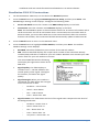
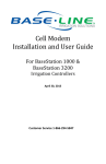
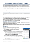
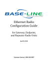
3G Cell Modem Installation and User Guide For BaseStation 1000 & BaseStation 3200 Irrigation Controllers in X and XS Cabinets September 18, 2014 Customer Service 1-866-294-5847 Baseline Inc. www.baselinesystems.com Phone 208-323-1634 FAX 208-323-1834 Toll Free 866-294-5847 ©2014 Baseline Inc. All Rights Reserved. FCC Compliance Information This equipment has been tested and found to comply with the limits for a Class B digital device, pursuant to part 15 of the FCC Rules. These limits are designed to provide reasonable protection against harmful interference in a residential installation. This equipment generates, uses and can radiate radio frequency energy, and if not installed and used in accordance with the instructions, may cause harmful interference to radio communications. However, there is no guarantee that interference will not occur in a particular installation. If this equipment does cause harmful interference to radio or television reception, which can be determined by turning the equipment off and on, the user is encouraged to try to correct the interference by one or more of the following measures: • • • • Reorient or relocate the receiving antenna. Increase the separation between the equipment and receiver. Connect the equipment into an outlet on a circuit different from that to which the receiver is connected. Consult the dealer or an experienced radio/TV technician for help. Table of Contents Introduction ....................................................................................................................... 1 Step 1 – Install the 3G Cell Modem Hardware ..................................................................... 1 Tools and Materials ............................................................................................................. 1 To install the cell modem hardware.................................................................................... 2 Step 2 – Check Your Firmware Version & Update if Necessary ............................................. 4 BaseStation 1000 Instructions............................................................................................. 4 To check the version of firmware on your BaseStation 1000 controller ........................ 4 To update the BaseStation 1000 firmware from the Baseline web site ......................... 5 BaseStation 3200 Instructions............................................................................................. 5 To check the version of firmware on your BaseStation 3200 controller ........................ 5 To update the BaseStation 3200 firmware from the Baseline web site ......................... 5 Step 3 – Activate Your SIM Card with Baseline .................................................................... 6 Step 4 – Verify the Cell Modem Connection in the Controller .............................................. 6 BaseStation 1000 Instructions............................................................................................. 6 BaseStation 3200 V12 Instructions ..................................................................................... 9 Setting the Data Usage Mode ...................................................................................... 10 Page i Installation and User Guide for Baseline Cell Modems in X and XS Cabinets Introduction In order to remotely connect with your BaseStation 1000 or 3200 irrigation controller and take advantage of BaseManager, the controller must be able to communicate over the Internet. Using a cell modem is one option for wireless Internet communication. The cell modem sends and receives data over a wireless carrier’s network. When you choose a cell modem communication package from Baseline, we provide the cell modem hardware, the SIM card from the wireless carrier, the firmware that activates the connection from your controller, and a 1-year subscription to a data plan with the wireless carrier. To install and establish communication through your cell modem, you need to perform the following tasks: Step 1 – Install the cell modem hardware in your BaseStation 1000 or 3200 enclosure. Step 2 – Check the firmware version on your controller and install an update if necessary. Step 3 – Activate your SIM card with Baseline. Step 4 – Verify the cell modem connection in the controller. Step 1 – Install the 3G Cell Modem Hardware IMPORTANT! The BL-CM3G cell modem hardware is compatible with all BaseStation 1000 controllers in X cabinet and pedestal (P) enclosures. BaseStation 3200 controllers in X and P enclosures shipped after April 16, 2014 are also compatible. Earlier BaseStation 3200 models require different 3G cell modem components. When the controller and cell modem are ordered together, the cell modem is already installed in the enclosure, but when the cell modem is ordered after the controller is in service, you will need to complete the installation. Tools and Materials • Philips head screwdriver • Needle-nose pliers • Cell modem module with power cable and screws • Antenna and antenna cable with connectors • Ethernet cable • Short piece of weather stripping Note: If you are not able to get a strong signal with the antenna that comes with the package, other options are available. Contact Baseline Support at 866-294-5847. Page 1 Installation and User Guide for Baseline Cell Modems in X and XS Cabinets To install the cell modem hardware 1. 2. We recommend that you back up your current configuration before starting this process in case you need to restore your system. Refer to Backing Up the Controller Programming in the BaseStation 1000 User Manual. Refer to Backing Up Your System in the BaseStation 3200 User Manual. Halt all watering while you install the cell modem hardware. BaseStation 1000: Press the OFF button. BaseStation 3200: Turn the dial to the OFF position. 3. Open the internal door of the BaseStation enclosure. 4. Remove the two screws that secure the black plastic cover over the controller PCA board as shown in Figure 1. Put the cover and the screws in a dust free location. 5. Find the orange power connector on the wires coming from the transformer (see Figure 2). Gently pull the connector away from the board to disconnect the power. 6. Remove the cell modem hardware and the antenna from its packaging. 7. Use needle-nose pliers to remove the rubber plug from the antenna port on the top of the enclosure. 8. Remove the nut and the lock washer from the bottom of the antenna, and then insert the stem of the antenna into the port on the top of the enclosure. 9. From the inside of the enclosure, place the lock washer on the stem of the antenna, and then thread the nut onto the stem (see Figure 3). Use a wrench to tighten the nut sufficiently to ensure that the antenna makes good contact with the outside of the enclosure. Figure 1 Figure 2 10. Remove the adhesive from the included piece of weather stripping, and then attach it as shown in Figure 3. Note: Because the lower attachment points are not used, the weather stripping is used to give extra support to the cell modem module. Page 2 Figure 3 Installation and User Guide for Baseline Cell Modems in X and XS Cabinets 11. Plug the power cord into the cell modem module as shown in Figure 4. 12. Plug the Ethernet cable into the Ethernet jack on the cell modem module as shown in Figure 5. 13. Attach the male SMA connector (small end) on the antenna cable to the connector on the cell modem module labeled WWAN Main as shown in Figure 5. 14. Align the holes on the cell modem module with the standoffs on the inside roof of the enclosure and use the screws provided to secure the board to the enclosure. Figure 4 15. Thread the coax connector on the antenna cable onto the stem of the antenna and hand-tighten it. 16. Plug the 5-pin connector from the cell modem power cord into the rear 5-pin terminal block (comm port 3) on right end of the controller board as shown in Figure 6. Note: If another connector is attached to the rear 5-pin terminal block, disconnect it, and then reconnect it to the front 5-pin terminal block. Figure 5 Figure 6 Page 3 Installation and User Guide for Baseline Cell Modems in X and XS Cabinets 17. Plug the other end of the Ethernet cable into the Ethernet jack on the back of the display board as shown in Figure 7. 18. Secure the Ethernet cable by pushing it into the cable clip. 19. Reconnect the orange power connector to the board in order to restore power to the controller (see Figure 2). 20. Reposition the black plastic cover over the controller PCA board, and then secure it with the two screws (see Figure 1). Figure 7 21. Close the enclosure door, and then restart the controller. BaseStation 1000: Press the RUN button. BaseStation 3200: Turn the dial to the RUN position. Step 2 – Check Your Firmware Version & Update if Necessary BaseStation 1000 Instructions BaseStation 1000 controllers running firmware version 1.11 and higher have integrated support for 3G cell modem communication. If your controller is running an earlier firmware version, you will need to download a firmware update onto a USB drive from the Baseline web site. To check the version of firmware on your BaseStation 1000 controller 1. On the BaseStation 1000, press the System Setup button. The System Setup menu displays. 2. Press the button to highlight the Firmware Update option, and then press the OK button to select it. The Firmware Update menu displays. 3. The USB Update option should be highlighted. If it is not highlighted, press the button to highlight it, and then press the OK button to select it. The USB Update screen displays the current firmware version at the top. If your controller is running a firmware version earlier than 1.11, you will need to download a firmware update onto a USB drive from the Baseline web site, and then install it on your controller. Page 4 Installation and User Guide for Baseline Cell Modems in X and XS Cabinets To update the BaseStation 1000 firmware from the Baseline web site You will need a computer with a USB port. This computer must have access to the Internet. You also need a USB (thumb) drive. You download the firmware from the Baseline web site to the USB drive. Then, you take the USB drive to the controller and install the update. 1. Go to the Baseline web site at the following URL: www.baselinesystems.com 2. On the home page, click Support. 3. In the left navigation bar, click Firmware Version Updates. 4. Click the BaseStation 1000 tab. 5. Follow the instructions on the web page to download the update. You can also click the Printable Instructions link on the web page to display the instructions in a format that is suitable for printing. BaseStation 3200 Instructions BaseStation 3200 controllers running firmware version 12.17 and higher have integrated support for 3G cell modem communication. If your controller is running an earlier firmware version, you will need to download a firmware update onto a USB drive from the Baseline web site. To check the version of firmware on your BaseStation 3200 controller On the BaseStation 3200, turn the dial to the Advanced position. The version number of the firmware displays at the bottom of the screen. If your controller is running firmware version earlier than 12.17, you will need to download a firmware update onto a USB drive from the Baseline web site, and then install it on your controller. To update the BaseStation 3200 firmware from the Baseline web site You will need a computer with a USB port. This computer must have access to the Internet. You also need a USB (thumb) drive. You download the firmware from the Baseline web site to the USB drive. Then, you take the USB drive to the controller and install the update. 1. On a computer that is connected to the Internet, go to the Baseline web site at the following URL: www.baselinesystems.com 2. On the home page, click Support. 3. In the left navigation bar, click Firmware Version Updates. Page 5 Installation and User Guide for Baseline Cell Modems in X and XS Cabinets 4. Click the BaseStation 3200 V12 tab. 5. Click the Printable Instructions link on the web page to display the instructions in a format that is suitable for printing. Step 3 – Activate Your SIM Card with Baseline 1. Fill out your information on the Wireless Service Activation Form that was enclosed with your cell modem communication package. This form is also available for download at www.baselinesystems.com. IMPORTANT! Baseline will not activate your SIM card until we have received your Wireless Service Activation Form with your valid billing information. Be sure to read the Wireless Service Terms and Conditions on page 2 of the Wireless Service Activation Form. 2. Fax or mail the form to Baseline. Upon receipt of the form, Baseline will activate your SIM card and then notify you. Baseline’s fax number is 208.323.1834. Note: Please allow 2 business days after Baseline receives your Wireless Service Activation Form for your SIM card to be activated. Step 4 – Verify the Cell Modem Connection in the Controller After Baseline informs you that your SIM card has been activated, go to your BaseStation controller and verify that the cell modem is connected to the cellular network. BaseStation 1000 Instructions 1. On the BaseStation 1000 controller, press the System Setup button. The System Setup menu displays. 2. Press the button to highlight the Network Setup option, and then press the OK button to select it. The Network Setup menu displays. After the cell modem hardware has been installed and is powered up, the Cell Modem Info option displays on the Network Setup menu. Page 6 Installation and User Guide for Baseline Cell Modems in X and XS Cabinets 3. Press the button to highlight the Cell Modem Info option, and then press the OK button to select it. The Cell Modem Info screen displays the following information: Cell Modem: Identifies the Baseline part number for the 3G cell modem. SIM: The first SIM field displays the unique serial number of the subscriber identity module (SIM) card that is installed in your cell modem. Baseline must activate your SIM card in order for your cell modem to connect. Prior to activation, the second SIM field displays Service Not Authorized. The second SIM field and the following line display the registration status of the SIM card. Signal Quality: This field displays a number from 1 – 10 that indicates the overall quality of the signal. The higher the number, the better the signal quality. Signal Strength: When your modem is connected, this field shows the strength of the connection in dBm and a signal strength meter represented by a series of bars. More bars mean a stronger signal. ◦ Excellent = -70 or better ◦ Good = -85 or better ◦ Fair = -100 or better ◦ Poor = worse than -100 Signal to Noise: This field shows the level of the signal when compared to the level of the background noise. The field also shows a signal to noise meter represented by a series of bars. More bars mean a better signal to noise ratio. ◦ Excellent = better than -5 ◦ Good = better than -9 ◦ Fair = better than -12 ◦ Poor = better than -15 ◦ Very Poor = worse than -15 Network: This field shows the status of the network connection. IP ADDR: This field shows the IP address assigned to the cell modem. Uptime: This field shows the number of minutes that the modem has been connected. Page 7 Installation and User Guide for Baseline Cell Modems in X and XS Cabinets 4. Press the Back button to return to the Network Setup menu and then press the or button to move to the BaseManager Setup option, and then press the OK button to select it. The BaseManager Setup screen displays. 5. Verify that there is a checkmark in the BaseManager Enabled field. 6. Press the button to move to the Data Usage Mode field. Choose one of the following options: Auto – Detects the type of communication module that is being used by the controller, and then automatically selects the appropriate mode. If you are using a communication module supplied by Baseline, we recommend that you use the Auto setting. Normal – When the controller is connected to a third-party device that is not limited by bandwidth or data plans, set the Data Usage Mode to Normal. In this mode, data is communicated as it happens. Low – When the controller is connected to a third-party cell modem, we recommend that you set the Data Usage Mode to Low. This setting restricts the data transfer to once per minute. 7. Press the Back button to return to the Network Setup menu and then press the or button to move to the BaseManager Info option, and then press the OK button to select it. The BaseManager Info screen displays. 8. Verify that Connected displays in the Status field and that Ethernet + 3G displays in the Interface field. 9. The origination date of your connection displays in the Connect Time field. 10. The number of bytes received from and sent to BaseManager displays in the Data (In/Out) field. 11. Press the Run button. You can add this controller to your BaseManager account using the Admin tool in BaseManager. If you do not have a BaseManager account, call Baseline to set one up. Baseline Support 866.294.5847 Page 8 Installation and User Guide for Baseline Cell Modems in X and XS Cabinets BaseStation 3200 V12 Instructions 1. On the BaseStation 3200 V12, turn the dial to the Network position. 2. Press the Next button to highlight BaseManager Server Setup, and then press Enter. The BaseManager Settings screen displays. Configure the following fields: Server URL Mode: Press the + button until DNS Lookup displays in the field. Connection: Press the + button until Ethernet displays in the field. Note: The Cell Modem option in the Connection field is for an earlier cell modem with a serial connection. For the 3G cell modem that is connected to the controller with an Ethernet cable, you must select Ethernet in the Connection field. After the controller finds the cell modem, the Connection field will automatically update to Ethernet+3G. 3. Press the Back button to return to the Network menu. 4. Press the Next button to highlight Cellular Modem, and then press Enter. The Cellular Modem Settings screen displays. BL-CM3G: Identifies the Baseline part number for the 3G cell modem. SIM: The first SIM field displays the unique serial number of the subscriber identity module (SIM) card that is installed in your cell modem. Baseline must activate your SIM card in order for your cell modem to connect. The second SIM field and the following line display the registration status of the SIM card. Signal Quality: This field displays a number from 1 – 10 that indicates the overall quality of the signal. The higher the number, the better the signal quality. Signal Strength: When your modem is connected, this field shows the strength of the connection in dBm. ◦ Excellent = -70 or better ◦ Good = -85 or better ◦ Fair = -100 or better ◦ Poor = worse than -100 Signal to Noise: This field shows the level of the signal when compared to the level of the background noise. ◦ Excellent = better than -5 ◦ Good = better than -9 ◦ Fair = better than -12 ◦ Poor = better than -15 ◦ Very Poor = worse than -15 Page 9 Installation and User Guide for Baseline Cell Modems in X and XS Cabinets Network: This field shows the status of the network connection. IP: This field shows the IP address assigned to the cell modem. Uptime: This field shows the number of minutes that the modem has been connected. 5. Press the Back button to return to the Network menu. 6. To find the origination date of your connection and see the number of bytes received from and sent to BaseManager, press the Back button to return to the Network menu. These details display in the lower-left corner of the menu screen. 7. Turn the dial to the Run position. Setting the Data Usage Mode When a controller is connected to a network, data is transferred back and forth across the network. The transferred data includes information such as network connection status updates, commands sent between the controller and BaseManager, and status updates from the controller to BaseManager. The BaseStation controller enables you to specify the Data Usage Mode setting. You can choose one of the following options: • Auto – Detects the type of communication module that is being used by the controller, and then automatically selects the appropriate mode. When you are using a communication module supplied by Baseline, we recommend that you set the Data Usage Mode to Auto. • Normal – When the controller is connected to a third-party device that is not limited by bandwidth or data plans, set the Data Usage Mode to Normal. In this mode, data is communicated as it happens. • Low – When the controller is connected to a third-party cell modem, we recommend that you set the Data Usage Mode to Low. This setting restricts the data transfer to once per minute. You can add this controller to your BaseManager account using the Admin tool in BaseManager. If you do not have a BaseManager account, call Baseline to set one up. Baseline Support 866.294.5847 Page 10