1
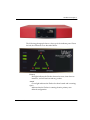
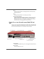
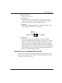
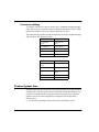
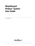
Firebox III
Hardware Guide
Firebox 500, Firebox 700, Firebox 1000, Firebox 2500, Firebox 4500
Copyright and Patent Information
Copyright© 1998 - 2003 WatchGuard Technologies, Inc. All rights reserved.
AppLock, AppLock/Web, Designing peace of mind, Firebox, Firebox 1000, Firebox
2500, Firebox 4500, Firebox II, Firebox II Plus, Firebox II FastVPN, Firebox III,
Firebox SOHO, Firebox SOHO 6, Firebox SOHO 6tc, Firebox SOHO|tc, Firebox
V100, Firebox V80, Firebox V60, Firebox V10, LiveSecurity, LockSolid,
RapidStream, RapidCore, ServerLock, WatchGuard, WatchGuard Technologies,
Inc., DVCP technology, Enforcer/MUVPN, FireChip, HackAdmin, HostWatch,
Make Security Your Strength, RapidCare, SchoolMate, ServiceWatch, Smart
Security. Simply Done., Vcontroller, VPNforce, The W-G logo are either registered
trademarks or trademarks of WatchGuard Technologies, Inc. in the United States
and/or other courtries.
Printed in the United States of America.
Part No: 1200188
Notice to Users
Information in this guide is subject to change without notice. Companies, names,
and data used in examples herein are fictitious unless otherwise noted. No part of
this guide may be reproduced or transmitted in any form or by any means,
electronic or mechanical, for any purpose, without the express written permission
of WatchGuard Technologies, Inc
ii
Hardware Guide
Contents
Limited Hardware Warranty ........................................................... 1
FCC Certification ............................................................................ 4
CE Notice ....................................................................................... 5
Industry Canada ............................................................................. 5
Taiwanese Notice ........................................................................... 6
VCCI Notice Class A ITE ................................................................ 6
Installing the Firebox III .................................................................. 7
Hardware requirements ................................................................. 7
Locating a Firebox within a network ............................................... 8
Connecting a Firebox ................................................................... 8
Running the QuickSetup Wizard .................................................. 11
Post-installation steps ................................................................. 12
Hardware Description .................................................................. 12
Firebox III front view (all models except Model 500 and 700) ......... 13
Firebox III front view (Model 500 and 700) .................................... 14
Firebox III rear view (all models except Model 500 and 700) .......... 16
Firebox III rear view (Model 500 and 700) ..................................... 17
Physical specifications (All models except Model 500 and 700) ...... 19
Physical specifications (Model 500 and 700) ................................. 19
Cross-over cabling ...................................................................... 20
Hardware Guide
iii
Firebox System Area
.................................................................... 20
Read-only system area ................................................................ 21
Enhanced System Mode .............................................................. 21
Managing flash disk memory ....................................................... 21
iv
Hardware Guide
Hardware Guide
The WatchGuard Firebox III is a specially designed and optimized
security appliance. Solid-state architecture removes the risk of hard-drive
failure and disk crashes. Three independent network interfaces allow you
to separate your protected office network from the Internet while
providing you an optional public interface for hosting Web, e-mail, or
FTP servers. Each network interface is independently monitored and
visually displayed on the front of the Firebox.
Limited Hardware Warranty
This Limited Hardware Warranty (the “Warranty”) applies to the enclosed
WatchGuard hardware product (the “Product”). BY USING THE PRODUCT,
YOU AGREE TO THE TERMS HEREOF. If you do not agree to these terms,
please return this package, along with proof of purchase, to the authorized dealer
from which you purchased it for a full refund. WatchGuard Technologies, Inc.
(”WatchGuard”) and you agree as follows:
1. Limited Warranty. WatchGuard warrants that upon delivery and for one (1)
year thereafter (the “Warranty Period”): (a) the Product will be free from material
defects in materials and workmanship, and (b) the Product, when properly installed
Hardware Guide
1
and used for its intended purpose and in its intended operating environment, will
perform substantially in accordance with WatchGuard applicable specifications.
This warranty does not apply to any Product that has been: (i) altered, repaired or
modified by any party other than WatchGuard; or (ii) damaged or destroyed by
accidents, power spikes or similar events or by any intentional, reckless or
negligent acts or omissions of any party. You may have additional warranties with
respect to the Product from the manufacturers of Product components. However,
you agree not to look to WatchGuard for, and hereby release WatchGuard from any
liability for, performance of, enforcement of, or damages or other relief on account
of, any such warranties or any breach thereof.
2. Remedies. If any Product does not comply with the WatchGuard warranties set
forth in Section 1 above, WatchGuard will, at its option, either (a) repair the
Product, or (b) replace the Product; provided, that you will be responsible for
returning the Product to the place of purchase and for all costs of shipping and
handling. Repair or replacement of the Product shall not extend the Warranty
Period. Any Product, component, part or other item replaced by WatchGuard
becomes the property of WatchGuard . WatchGuard shall not be responsible for
return of or damage to any software, firmware, information or data contained in,
stored on, or integrated with any returned Products.
3. Disclaimer and Release. THE WARRANTIES, OBLIGATIONS AND
LIABILITIES OF WATCHGUARD, AND YOUR REMEDIES, SET FORTH IN
PARAGRAPHS 1 AND 2 ABOVE ARE EXCLUSIVE AND IN SUBSTITUTION
FOR, AND YOU HEREBY WAIVE, DISCLAIM AND RELEASE ANY AND ALL
OTHER WARRANTIES, OBLIGATIONS AND LIABILITIES OF WATCHGUARD
AND ALL OTHER RIGHTS, CLAIMS AND REMEDIES YOU MAY HAVE
AGAINST WATCHGUARD, EXPRESS OR IMPLIED, ARISING BY LAW OR
OTHERWISE, WITH RESPECT TO ANY NONCONFORMANCE OR DEFECT IN
THE PRODUCT (INCLUDING, BUT NOT LIMITED TO, ANY IMPLIED
WARRANTY OF MERCHANTABILITY OR FITNESS FOR A PARTICULAR
PURPOSE, ANY IMPLIED WARRANTY ARISING FROM COURSE OF
PERFORMANCE, COURSE OF DEALING, OR USAGE OF TRADE, ANY
WARRANTY OF NONINFRINGEMENT, ANY WARRANTY OF
UNINTERRUPTED OR ERROR-FREE OPERATION, ANY OBLIGATION,
LIABILITY, RIGHT, CLAIM OR REMEDY IN TORT, WHETHER OR NOT
ARISING FROM THE NEGLIGENCE (WHETHER ACTIVE, PASSIVE OR
IMPUTED) OR FAULT OF WATCHGUARD OR FROM PRODUCT LIABILITY,
STRICT LIABILITY OR OTHER THEORY, AND ANY OBLIGATION,
LIABILITY, RIGHT, CLAIM OR REMEDY FOR LOSS OR DAMAGE TO, OR
CAUSED BY OR CONTRIBUTED TO BY,THE PRODUCT).
2
Hardware Guide
Limited Hardware Warranty
4. Limitation of Liability. WATCHGUARD TECHNOLOGIES’ LIABILITY
(WHETHER ARISING IN CONTRACT (INCLUDING WARRANTY), TORT
(INCLUDING ACTIVE, PASSIVE OR IMPUTED NEGLIGENCE AND STRICT
LIABILITY AND FAULT) OR OTHER THEORY) WITH REGARD TO ANY
PRODUCT WILL IN NO EVENT EXCEED THE PURCHASE PRICE PAID BY
YOU FOR SUCH PRODUCT. THIS SHALL BE TRUE EVEN IN THE EVENT OF
THE FAILURE OF ANY AGREED REMEDY. IN NO EVENT WILL
WATCHGUARD TECHNOLOGIES BE LIABLE TO YOU OR ANY THIRD PARTY
(WHETHER ARISING IN CONTRACT (INCLUDING WARRANTY), TORT
(INCLUDING ACTIVE, PASSIVE OR IMPUTED NEGLIGENCE AND STRICT
LIABILITY AND FAULT) OR OTHER THEORY) FOR COST OF COVER OR FOR
ANY INDIRECT, SPECIAL, INCIDENTAL, OR CONSEQUENTIAL DAMAGES
(INCLUDING WITHOUT LIMITATION LOSS OF PROFITS, BUSINESS, OR
DATA) ARISING OUT OF OR IN CONNECTION WITH THIS WARRANTY OR
THE USE OF OR INABILITY TO USE THE PRODUCT, EVEN IF
WATCHGUARD TECHNOLOGIES HAS BEEN ADVISED OF THE
POSSIBILITY OF SUCH DAMAGES. THIS SHALL BE TRUE EVEN IN THE
EVENT OF THE FAILURE OF ANY AGREED REMEDY.
5. Miscellaneous Provisions. This Warranty will be governed by the laws of the
state of Washington, U.S.A., without reference to its choice of law rules. The
provisions of the 1980 United Nations Convention on Contracts for the
International Sales of Goods, as amended, shall not apply. You agree not to
directly or indirectly transfer the Product or associated documentation to any
country to which such transfer would be prohibited by the U.S. Export laws and
regulations. If any provision of this Warranty is found to be invalid or
unenforceable, then the remainder shall have full force and effect and the invalid
provision shall be modified or partially enforced to the maximum extent permitted
by law to effectuate the purpose of this Warranty. This is the entire agreement
between WatchGuard and you relating to the Product, and supersedes any prior
purchase order, communications, advertising or representations concerning the
Product AND BY USING THE PRODUCT YOU AGREE TO THESE TERMS. No
change or modification of this Agreement will be valid unless it is in writing, and is
signed by WatchGuard.
Hardware Guide
3
FCC Certification
This device has been tested and found to comply with limits for a Class A
digital device, pursuant to Part 15 of the FCC Rules. Operation is subject
to the following two conditions:
• This device may not cause harmful interference.
4
Hardware Guide
CE Notice
•
This device must accept any interference received, including
interference that may cause undesired operation.
CE Notice
The CE symbol on your WatchGuard Technologies equipment indicates
that it is in compliance with the Electromagnetic Compatibility (EMC)
directive and the Low Voltage Directive (LVD) of the European Union
(EU).
Industry Canada
This Class A digital apparatus meets all requirements of the Canadian
Interference-Causing Equipment Regulations.
Cet appareil numerique de la classe A respecte toutes les exigences du
Reglement sur le materiel broulleur du Canada.
Hardware Guide
5
Taiwanese Notice
VCCI Notice Class A ITE
6
Hardware Guide
Installing the Firebox III
Installing the Firebox III
Easily installed into your network, the rack-mountable Firebox plugs in at
the Internet connection of your offices to implement security policies and
protection.
Hardware requirements
WatchGuard recommends physically installing a Firebox III under the
following conditions:
• Securely rack-mounted
• Placed in a dry, temperature-controlled environment that does not
exceed 80 degrees F
• Placed in a secured environment, such as a locked LAN room, or
similar space, to prevent physical compromise by unprivileged
personnel
• Connected to conditioned power to prevent damage caused by power
spikes and other power fluctuations
The following minimum hardware requirements pertain to the
Management Station–the computer that administers the Firebox. This
computer runs the Control Center software, which provides access to
WatchGuard Firebox System applications.
Hardware Guide
Hardware feature
Minimum requirements (Management Station)
CPU
Pentium II
Memory
Same as for operating system.
Recommended:
64 MB for Windows 98
64 MB for Windows NT 4.0
64 MB for Windows 2000 Professional
256 MB for Windows 2000 Server
Hard disk space
25 MB to install all WatchGuard modules
15 MB minimum for log file
Additional space as required for log files
Additional space as required for multiple
configuration files
CD-ROM drive
One CD-ROM drive to install WatchGuard from its
CD-ROM distribution disk
7
Locating a Firebox within a network
One of the first steps in installing a Firebox is determining where to place
it within the network. Nearly always, a Firebox is placed directly behind
the Internet router, as pictured below. This is the most effective location
for the Firebox to operate correctly and protect your network.
Connecting a Firebox
After you have decided where to place the Firebox, the next task is to
make all the hardware connections. See “Firebox III rear view (all models
except Model 500 and 700)” on page 16 or “Firebox III rear view (Model
500 and 700)” on page 17 (depending on which model Firebox you are
using) to view a figure showing the connections on the back of the
Firebox.
8
Hardware Guide
Installing the Firebox III
You can connect to and initialize a new Firebox in several ways:
• Using TCP/IP. This is the quickest way to configure a Firebox in most
situations.
• Using a serial cable. Use this method if you want to isolate the Firebox
during configuration.
• Using a modem. Use this method if the Firebox is located remotely
from the Management Station.
• Using remote provisioning. Use this method in the case where a
router sits between the Management Station (the computer on which
you install the WatchGuard Firebox System Control Center software)
and the Firebox network connection.
Cabling a Firebox using TCP/IP
This process uses TCP/IP over Ethernet to connect and initialize a new
Firebox. The Firebox will automatically obtain its IP address.
1
Place the Firebox on a desktop or in a rack in a location convenient to
the external router.
2
Use the red (cross-over) cable (provided with the Firebox) to connect
the Firebox Trusted interface to the same network as the computer
that will act as the Firebox Management Station.
If the Firebox is to be connected to the Firebox Management Station in isolation,
you must use either a hub or the red cable.
3
Install the power cord from the AC receptacle on the Firebox to a
power source.
4
When prompted to do so during the QuickSetup wizard (described in
“Running the QuickSetup Wizard” on page 11), select Use TCP/IP to
Configure as the confirmation access method.
Cabling a Firebox for serial cable initialization
This process requires that you manually create an IP address.
1
2
Hardware Guide
Place the Firebox in a location convenient to the Management Station.
Use the blue serial cable to connect the Firebox console port with the
Management Station COM port. Use the red crossover cable to
connect the Trusted interface to the Management Station Ethernet
port.
9
3
Install the power cord from the Firebox AC receptacle to a power
source.
4
When prompted to do so during the QuickSetup wizard (described in
“Running the QuickSetup Wizard” on page 11), select Use Serial
Cable to Assign IP Address as the configuration access method.
Initializing a Firebox using a modem
The following are required when using a modem:
• Management Station running Firebox System 4.6 or later and
equipped with a modem, Dial-Up Networking software, and a
working telephone line.
• Any Firebox III model, equipped with an external modem, a modem
cable, and a working telephone line.
1
Use the blue null serial cable and adaptors included with the Firebox
to connect the Firebox CONSOLE port and external serial port in a
loopback configuration.
2
Turn the power on the Firebox off, then on. Confirm that the SysB
light is lit.
The Firebox is now ready to accept the out-of-band connection.
Initializing a Firebox using remote provisioning
Use remote provisioning to initialize a Firebox in the case where a router
sits between the Management Station and the Firebox network
connection. Because of the flexibility of being able to initialize a Firebox
from virtually any location on a network, remote provisioning is a very
versatile option. However, it has the following restrictions:
• During provisioning, the Firebox and the router should be the only
devices on the network.
• You must be able to flush the local router’s ARP tables, preferably by
rebooting the router.
• The Firebox must be initialized with Firebox System 4.6 or later.
Make sure the following conditions exist prior to using remote
provisioning:
• The Firebox is attached as the only device behind a working router.
10
Hardware Guide
Installing the Firebox III
•
•
•
The Management Station is running Firebox System 4.6 or later, which
has IP connectivity to the network on which the Firebox is connected.
The network address and the netmask of the net behind the router are
known.
One or more unused IP connections are behind the router.
During remote provisioning, one light appears on the front panel Traffic
Volume Indicator (on Models 1000, 2500, and 4500 only) for each
successful IP address the Firebox claims. The Firebox can claim up to
eight addresses.
The Process Load Indicator on Models 1000, 2500, and 4500 marks the
total number of different MAC addresses the Firebox sees on the cable. If
the number exceeds eight, the Firebox stops claiming addresses; the SysA
light remains lit. This feature is designed to prevent an uninitialized
Firebox from claiming addresses on a busy LAN. (If this happens, reboot
into Enhanced System Mode and try again.)
1
Attach both the Firebox External interface and the router’s interface to
a common local area network, or use the red cross-over cable to
connect them directly.
2
Turn the Firebox off and then back on. Allow time for the Firebox to
boot. Confirm that there is a flashing pattern with a red, blinking,
Trusted deny light on the lower edge of the Security Triangle Display.
3
Flush the router ARP cache.
4
From Policy Manager on the Management Station, select File => Open
Firebox.
5
Select an unused IP address behind the router on the same network to
which the Firebox is attached. Set the Firebox’s read-write passphrase
to wg. Set the timeout to 90 seconds. Click OK.
6
If the procedure is successful, the open operation on the Management
Station completes. You can then follow regular procedures described
in the User Guide to configure and download a new flash image to the
Firebox.
Rebooting the router will usually accomplish this.
Running the QuickSetup Wizard
The final step of the WatchGuard Firebox System installation is to run the
QuickSetup wizard. The QuickSetup wizard creates a basic configuration
Hardware Guide
11
file and saves it to the primary area of the Firebox flash disk. The Firebox
loads the primary configuration file when it boots. The QuickSetup
wizard also writes a basic configuration file called wizard.cfg to the
Management Station hard disk.
By default, the QuickSetup wizard starts automatically after you finish
installing the Firebox System software. To manually start the QuickSetup
wizard from the Windows desktop, select Start => Programs =>
WatchGuard => QuickSetup Wizard.
For details on running the QuickSetup wizard, see Firebox System Install
Guide.
Post-installation steps
The Firebox can now communicate with the Management Station over the
network. Perform the following post-installation steps:
1
If you initialized the Firebox using the serial cable, you must now
place the Firebox within your network. Initially, this must be done
over the Trusted interface.
The most common location for the Firebox is physically between the Internet router
and connections to your trusted and optional networks. See “Locating a Firebox
within a network” on page 8.
2
Connect the Ethernet lines to the Firebox Trusted, External, and
Optional interfaces as appropriate.
Specific connections vary according to the drop-in or routed network configuration
created. You are not required to connect the Optional interface if it is not part of
your network configuration.
3
Reboot the Management Station.
4
You can now customize your security policies. See the User Guide for
additional configuration instructions.
If you designated the Management Station as the primary event processor, the
LiveSecurity Event Processor starts.
Hardware Description
The Firebox III has indicator lights on the front and connections on the
back.
12
Hardware Guide
Hardware Description
Firebox III front view (all models except Model 500 and
700)
Indicators for the Firebox III Model 1000, Model 2500, and Model 4500 are
on a central back-lit indicator panel. The following photograph shows the
entire front view.
The photograph below shows a close-up of the indicator panel. From the
left, the indicators are as described on the next page.
Disarm
Red light indicates the Firebox detected an error, shut down its
interfaces, and will not forward any packets. Reboot the Firebox.
Armed
Green light indicates the Firebox has been booted and is running.
Hardware Guide
13
Sys A
Indicates that the Firebox is running from its primary userdefined configuration.
Sys B
Indicates that the Firebox is running from the read-only factory
default system area.
Power
Indicates that the Firebox is currently powered up.
Security Triangle Display
Indicates traffic between Firebox interfaces. Green arrows briefly
light to indicate allowed traffic between two interfaces in the
direction of the arrows. A red light at a triangle corner indicates
that the Firebox is denying packets at that interface.
Traffic
A stack of lights that functions as a meter to indicate levels of
traffic volume through the Firebox. Low volume indicators are
green, while high volume indicators are yellow. The display
updates three times per second. The scale is exponential: the first
light represents 64 packets/second, the second light represents
128 packets/second, increasing to the eighth light which
represents 8,192 packets/second.
Load
A stack of lights that functions as a meter to indicate the system
load average. The system load average is the average number of
processes running (not including those in wait states) during the
last minute. Low average indicators are green, while high average
indicators are yellow. The display updates three times per second.
The scale is exponential with each successive light representing a
doubling of the load average. The first light represents a load
average of 0.15. The most significant load factor on a Firebox is the
number of proxies running.
Firebox III front view (Model 500 and 700)
Firebox III Model 500 and 700 indicators are on a central back-lit indicator
panel. The following photograph shows the entire front view.
14
Hardware Guide
Hardware Description
The following photograph shows a close-up of the indicator panel. From
the left, the indicators are as described below.
Disarm
Armed
Sys A
Sys B
Power
Disarm
Red light indicates the Firebox detected an error, shut down its
interfaces, and will not forward any packets.
Armed
Green light indicates the Firebox has been booted and is running.
Sys A
Indicates that the Firebox is running from its primary userdefined configuration.
Hardware Guide
15
Sys B
Indicates that the Firebox is running from the read-only factory
default system area.
Power
Indicates that the Firebox is currently powered up.
Security Triangle Display
Indicates traffic between Firebox interfaces. Green arrows briefly
light to indicate allowed traffic between two interfaces in the
direction of the arrows. A red light at a triangle corner indicates
that the Firebox is denying packets at that interface.
Firebox III rear view (all models except Model 500 and
700)
The rear view of the Firebox III Model 1000, Model 2500, and Model 4500
contains ports and jacks for connectivity as well as a power switch. From
the left, rear panel features are as described on the next page:
AC Receptacle
Accepts the detachable AC power cord supplied with the Firebox.
Power Switch
Turns the Firebox on or off.
16
Hardware Guide
Hardware Description
PCI Expansion Slot
Reserved for future use.
Factory Default
This button is active only during the boot process. To boot the
Firebox to SYS B, press this button and hold it down for 20-60
seconds (or until you see the Sys B light come on).
Console Port
Connects to the Management Station or modem through a serial
cable supplied with the Firebox using PPP.
.
Yel: 10
Grn: 100
Speed
A
Traffic
Ethernet Ports
(Shown on the previous page) Indicators for each network
interface display link status, card speed, and activity. The network
interface cards (NICs) are auto-sensing and adapt to wire speed
automatically. The speed indicator lights when there is a good
physical connection to the Firebox. When the card runs at 10Mbit,
the speed indicator is yellow. When the card runs at 100 Mbit, the
speed indicator is green. The amber traffic indicator blinks when
traffic is passing through the Firebox.
Firebox III rear view (Model 500 and 700)
The rear view of the Firebox III Model 500 and 700 contains ports and
jacks for connectivity as well as a power switch. From the left, rear panel
features are as described below:
Hardware Guide
17
AC Receptacle
Accepts the detachable AC power cord supplied with the Firebox.
Power Switch
Turns the Firebox on or off.
Factory Default
This button is active only during the boot process. To boot the
Firebox to SYS B, press this button and hold it down for 20-60
seconds (or until you see the Sys B light come on).
Console Port
Connects to the Management Station or modem through a serial
cable supplied with the Firebox using PPP.
.
Yel: 10
Grn: 100
Speed
A
Traffic
Ethernet Jacks
(Shown above) Indicators for each network interface display link
status, card speed, and activity. The network interface connections
18
Hardware Guide
Hardware Description
(NICs) are auto-sensing and adapt to wire speed automatically. The
speed indicator lights when there is a good physical connection to the
Firebox. When the card runs at 10Mbit, the speed indicator is yellow.
When the card runs at 100 Mbit, the speed indicator is green. The
amber traffic indicator blinks when traffic is passing through the
Firebox.
Physical specifications (All models except Model 500 and
700)
•
•
•
•
•
•
•
•
Three RJ-45 10/100Tx Ethernet interfaces
1 DB-9 serial port
PCI expansion option
500 MHz AMD K6-III processor
300 MHz AMD K6-II processor (model 1000 only)
64-MB SDRAM (model 1000)
128-MB SDRAM (model 2500)
264-MB SDRAM (model 4500)
8-MB flash disk
100-240 VAC Autosensing, 50/60 Hz
Height: 2.85”; Width: 15.5 “; Depth: 10.5”
Physical specifications (Model 500 and 700)
•
•
•
•
•
•
•
Hardware Guide
Three RJ-45 10/100Tx Ethernet interfaces
1 DB-9 serial port
233 MHz AMD K6-II processor
64-MB SDRAM
8-MB flash disk
100-240 VAC Autosensing, 50/60 Hz
Height: 2.85”; Width: 15.5 “; Depth: 10.5”
19
Cross-over cabling
To connect a Firebox to a hub or switch, use a standard, straight-through
cable. However, if you plan to connect a Firebox directly to a router, either
purchase or build a cross-over cable for RJ-45 (Cat5) wire.
The tables below provide pin-out descriptions for both a straight-through
and a RJ-45 (Cat5) cross-over cable.
Pin Number
Pin Number
1 (Transmit
Plus)
1 (Transmit
Plus)
2 (Transmit -)
2 (Transmit -)
3 (Receive Plus)
3 (Receive Plus)
6 (Receive -)
6 (Receive -)
4,5,7,8
Not Used
Pin Number
Pin Number
1 (Transmit
Plus)
3 (Receive Plus)
2 (Transmit -)
6 (Receive -)
3 (Receive Plus)
1 (Transmit
Plus)
6 (Receive -)
2 (Transmit -)
4,5,7,8
Not Used
Firebox System Area
WatchGuard ships the Firebox III with a fixed, baseline set of functionality
stored on the read-only system area of the Firebox flash disk memory. It is
possible to start the Firebox using this read-only system area when the
primary user area is misconfigured or corrupted. This functionality
allows you to:
• Troubleshoot problems where all access to the Firebox is lost
20
Hardware Guide
Firebox System Area
•
Reset Firebox passphrases when you do not know or have forgotten
them
Fireboxes shipped before LiveSecurity System 4.1 shipped with the
original, standard functionality called the read-only system area.
Fireboxes shipped with LiveSecurity System 4.1 or later contain both the
older functions and a new set of features designed to enhance usability,
called the enhanced system area.
Read-only system area
The Firebox III has a read-only system area that the unit can be booted
into using the serial cable shipped with the Firebox. When a Firebox is
running from the read-only system area, the Sys B light and the Armed
light are both illuminated.
With the Firebox running the read-only system area, use one of two
methods to initialize the Firebox and prepare it for configuration:
• Factory default switch on back
• Out-of-band, using a modem
• Direct, using a serial cable
However, do not attempt to use the read-only system area configuration
file as a base or template for your working configuration. It will not work.
You must create a new configuration file using the QuickSetup Wizard or
open an existing configuration file.
Enhanced System Mode
By default, Firebox III boots into an Enhanced System Mode. When a
Firebox is running from the Enhanced System Mode, the Sys A light on
the front panel flickers yellow in a repeating pattern.
Managing flash disk memory
The Flash Disk Management Tool performs specific tasks involving the
Firebox flash memory. The flash disk is divided into three areas:
• System (SysB)– Contains a permanently stored, basic Firebox
software image with the passphrase wg.
Hardware Guide
21
•
•
Primary (SysA)– Contains the Firebox software image used in
normal operation and the enhanced read-only system area.
Backup– Contains the Firebox software image.
Making a backup of the Firebox software
To ensure that you always have a backup version of the current Firebox
software, copy the image stored in the primary area to the Firebox flash
disk backup area. From Control Center:
1
Click the Control Center Main Menu button (shown at
right), which is located on the upper-left corner of
Control Center.
2
3
Select Tools => Advanced => Flash Disk Management.
4
Click Yes.
5
Use the Firebox drop list to select a Firebox or type the IP address
used by the Management Station to communicate with the Firebox.
Enter the configuration (read/write) passphrase. Click OK.
Select Make Backup of Current Image. Click Continue.
A verification prompt appears. Verify that the Management Station connects to the
Firebox Trusted interface either over the network (TCP/IP) or via a modem using
out-of-band management.
The Connect To Firebox dialog box appears.
When the backup is successful, an Operation Complete alert appears.
6
Click OK.
You do not need to reboot the Firebox.
Restoring a backup configuration file
Backing up and restoring a configuration file acts not only on the
configuration file but on the entire flash image. This is important to note if
you are loading a new version, patch, or component onto the Firebox.
Restore the backup configuration file to the primary area of the Firebox
flash disk when:
• You incorrectly overwrite the primary configuration file.
• The primary configuration file is incorrectly configured or is
otherwise unusable.
22
Hardware Guide
Firebox System Area
Note that this procedure is possible only when a backup image is on the
backup area of the Firebox’s flash disk. There is no backup image on the
Firebox until you copy one there.
1
Click the Control Center Main Menu button (shown at
right), which is located on the upper-left corner of
Control Center.
2
3
Select Tools => Advanced => Flash Disk Management.
4
Click Yes.
5
Use the Firebox drop list to select a Firebox or type the IP address
used by the Management Station to communicate with the Firebox.
Enter the configuration (read/write) passphrase. Click OK.
Select Restore Backup Image. Click Continue.
A verification prompt appears. Verify that the Management Station connects to
the Firebox Trusted interface either over the network (TCP/IP) or via a modem
using out-of-band management.
The Connect To Firebox dialog box appears.
The Firebox copies the backup image from the backup area to the primary area of
its flash disk and reboots from the backup file.
Hardware Guide
23
24
Hardware Guide
Index
A
AC receptacle 16
Armed light 13, 15
B
backup area 22
backup image 22
C
cabling
cross-over 20
using serial cable 9
using TCP/IP 9
certification, FCC 4
configuration file
and QuickSetup Wizard 12
Connect To Firebox dialog box 22
console port 17, 18
Control Center button 22, 23
cross-over cabling 20
D
F
Factory Default button 17, 18
factory default system area
and Sys B light 14, 16
FCC certification 4
Firebox III
booting 17, 18
cabling using TCP/IP 9
front panel 13, 15
hardware connections for 8
hardware description 12
hardware requirements 7
initializing using remote provisioning 10
installation 7
introduction 1
location within network 8
physical specifications 19
ports and jacks 16, 17
read-only system area 20, 21
rear panel 16, 17
system load average 14
traffic through 14, 16
using serial cable 9
Firebox III front view
Model 1000 13
Model 2500 13
Model 4500 13
Model 700 14
Firebox III rear view
Model 1000 16
Model 2500 16
Model 4500 16
Model 700 17
Firebox software
making backup 22
restoring backup 22
Flash Disk Management Tool 21
flash memory 21
Disarm light 13, 15
E
enhanced system area 21
Enhanced System Mode 21
Ethernet ports 17, 18
H
hardware
description 12
requirements 7
I
indicator
load 14
Hardware Guide
25
traffic 14
installation 7
R
L
read-only system area 20, 21
remote provisioning
and Process Load Indicator 11
and Traffic Volume Indicator 11
described 10
lights
Armed 13, 15
Disarm 13, 15
Power 14, 16
Sys A 14, 15
Sys B 14, 16
limited hardware warranty 1
load indicator 14
M
Management Station
described 7
N
network, Firebox located in 8
P
PCI expansion slot 17, 18
physical specifications 19
ports 16, 17
Power light 14, 16
power switch 16, 18
primary area 22
Process Load Indicator
and remote provisioning 11
described 14
provisioning, remote 10
S
Security Triangle Display 14, 16
Sys A light
and Enhanced System Mode 21
described 14, 15
Sys B light
and read-only system area 21
described 14, 16
system area 21
enhanced 21
read-only 21
system load average 14
T
TCP/IP, cabling Firebox using 9
traffic indicator 14
Traffic Volume Indicator
and remote provisioning 11
described 14
W
wizard.cfg 12
Q
QuickSetup Wizard
automatic startup 12
described 11
starting manually 12
26
Hardware Guide