1
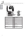
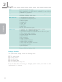
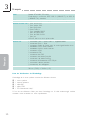
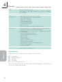
CM64-AL
System Board User’s Manual
Carte Mère Manuel Pour Utilisateur
System-Platine Benutzerhandbuch
Manual del Usuario de Placas Base
Ðóêîâîäñòâî Ïîëüçîâàòåëÿ
935-CM64A1-000G
90200548
Quick Setup
Guide
1
Quick Setup Guide
Copyright
This publication contains information that is protected by copyright. No part of it
may be reproduced in any form or by any means or used to make any
transformation/adaptation without the prior written permission from the copyright
holders. This publication is provided for informational purposes only. The
manufacturer makes no representations or warranties with respect to the
contents or use of this manual and specifically disclaims any express or implied
warranties of merchantability or fitness for any particular purpose. The user will
assume the entire risk of the use or the results of the use of this document.
Further, the manufacturer reserves the right to revise this publication and make
changes to its contents at any time, without obligation to notify any person or
entity of such revisions or changes. © 2005. All Rights Reserved.
Trademarks
Product names or trademarks appearing in this manual are for identification
purpose only and are the properties of the respective owners.
Caution
To avoid damage to the system, use the correct AC input voltage range..
To reduce the risk of electric shock, unplug the power cord before removing the
system chassis cover for installation or servicing. After installation or servicing,
cover the system chassis before plugging the power cord.
Battery: 1. Danger of explosion if battery incorrectly replaced. 2. Replace only
with the same or equivalent type recommend by the manufacturer. 3. Dispose of
used batteries according to the battery manufacturer’s instructions.
Notice
The system board and accessories you receive in the package may not come
similar to the information stated in this manual. This may differ in accordance to
the sales region or models in which it was sold. For more information about the
standard package in your region, please contact your dealer or sales
representative.
FCC and DOC Statement on Class B
This equipment has been tested and found to comply with the limits for a Class
B digital device, pursuant to Part 15 of the FCC rules. These limits are designed
to provide reasonable protection against harmful interference when the
equipment is operated in a residential installation. This equipment generates, uses
and can radiate radio frequency energy and, if not installed and used in accordance with the instruction manual, may cause harmful interference to radio
communications. However, there is no guarantee that interference will not occur
in a particular installation. If this equipment does cause harmful interference to
radio or television reception, which can be determined by turning the equipment
off and on, the user is encouraged to try to correct the interference by one or
more of the following measures:
• Reorient or relocate the receiving antenna.
• Increase the separation between the equipment and the receiver.
• Connect the equipment into an outlet on a circuit different from that to
which the receiver is connected.
• Consult the dealer or an experienced radio TV technician for help.
Notice:
1. The changes or modifications not expressly approved by the par ty
responsible for compliance could void the user's authority to operate the
equipment.
2. Shielded interface cables must be used in order to comply with the emission
limits.
2
Table of Contents
Chapter 1
Quick Setup Guide.............................................
4
1
Quick Setup
Guide
Quick Setup Guide
Chapter 2
English...................................................................... 17
Chapter 3
Français.................................................................... 19
Chapter 4
Deutsch............................................................................... 21
Chapter 5
Español............................................................................ 23
Chapter 6
Ðóññêèé....................................................................... 25
Chapter 7
Japanese........................................................................ 27
The user’s manual in the provided CD contains detailed information about the system board. If, in some
cases, some information doesn’t match those shown in this manual, this manual should always be regarded as the most updated version.
Le manuel d’utilisateur dans le CD muni contient renseignement détaillé au sujet de carte de système. Si,
en quelque cas, quelque renseignement n’appareille de ce que dit dans ce manuel, ce manuel doit
toujours être considéré comme la plus nouvelle version.
Das Benutzerhandbuch in der angebotenen CD enthält detaillierte Informationen über die Hauptplatine.
Wenn in manchen Fällen manche Informationen nicht denjenigen Informationen dargestellt in diesem
Handbuch entsprechen, soll dieses Handbuch als die meist aktualisierte Ausgabe gelten.
El uso explicativo contene información detalle sobre la sistema board en el CD preparativo. Si en algún
caso, la información no es igual con el uso explicativo, necesita ver el uso explicativo, esque es más
nuevo.
 ðóêîâîäñòâå ïîëüçîâàòåëÿ íà ïðåäîñòàâëÿåìîì CD äèñêå ñîäåðæèòñÿ ïîäðîáíàÿ
èíôîðìàöèÿ î ìàòåðèíñêîé ïëàòå. Èíîãäà íàïå÷àòàííîå ðóêîâîäñòâî ìîæåò íå
ñîâïàäàòü ðóêîâîäñòâîì íà CD, òàê êàê ïîñëåäíåå íàèáîëåå ÷àñòî îáíîâëÿåòñÿ è
ÿâëÿåòñÿ ñàìûì ñâåæèì.
3
Quick Setup
Guide
1
4
Quick Setup Guide
Chapter 1 - Quick Setup Guide
System Board Layout
System Memory
DIMM Power LED
DIMM 1
DIMM 2
.
.
. . .
.
.
.
1
Quick Setup
Guide
Quick Setup Guide
Warning:
When the DIMM Power LED lit red, it indicates that power is
present on the DIMM sockets. Power-off the PC then unplug the
power cord prior to installing any memory modules. Failure to do so
will cause severe damage to the motherboard and components.
Jumpers
Clear CMOS Data
JP3
X
1
2 3
1-2 On: Normal
(default)
1
2 3
2-3 On:
Clear CMOS Data
5
Quick Setup
Guide
1
Quick Setup Guide
Onboard Audio Codec Select
1
X
2 3
1
2 3
JP4
JP4
JP6
JP6
1-2 On:
Onboard Audio
Codec Enabled
(default)
2-3 On:
Onboard Audio
Codec Disabled
PS/2 Power Select
JP11
X
1
1
2
2
3
3
1-2 On: 5V
(default)
2-3 On: 5VSB
Important:
The 5VSB power source of your power supply must support
≥720mA.
6
USB Power Select
USB 1-2
(JP1)
X
3
2 1
1-2 On: 5V
(default)
USB 3-4
(JP10)
1
2 3
3
2 1
2-3 On: 5VSB
1
1
Quick Setup
Guide
Quick Setup Guide
2 3
X
1-2 On: 5V
(default)
2-3 On: 5VSB
Important:
If you are using the Wake-On-USB Keyboard/Mouse function for 2
USB ports, the 5VSB power source of your power supply must
support ≥1.5A. For 3 or more USB ports, the 5VSB power source of
your power supply must support ≥2A.
7
Quick Setup
Guide
1
Quick Setup Guide
CPU FSB Select
3 2 1
X
FSB
JP8
JP9
Auto
1-2 On
1-2 On
66MHz
2-3 On
2-3 On
100MHz
2-3 On
All Off
133MHz
All Off
All Off
JP8
JP9
JP8 and JP9 are used to select the front side bus of the CPU. The
default setting is Auto. The system will run according to the front
side bus of the CPU installed on the system board. You can also set
the FSB fixed at 100MHz or 133MHz.
Important:
• If you are using a CPU whose frequency has been locked
by the manufacturer, overclocking will have no effect.
• Overclocking may result to the CPU’s or system’s instability
and are not guaranteed to provide better system
performance. If you are unable to boot your system due to
overclocking, make sure to set these jumpers back to their
default settings.
8
Rear Panel I/O Ports
PS/2
Mouse
PS/2
K/B
LAN
Parallel
USB 1-2
COM
GAME/MIDI
1
Quick Setup
Guide
Quick Setup Guide
VGA
Line- Line- Micout in
in
Internal I/O Connectors
VCC
-Data
+Data
GND
N. C.
USB (Universal Serial Bus)
10
9W
VCC
-Data
+Data
GND
Key
2
1
USB 3-4
9
Mic
Mic Power
AuD_R_Out
N. C.
AuD_L_Out
GND
AuD_Vcc
AuD_R_Return
Key
AuD_L_Return
CD
TD
GND
RTS
RI
RD
DTR
DSR
CTS
Quick Setup
Guide
1
10
Quick Setup Guide
COM (Serial) Port
2
1
9
2
1
W
Front Audio
10
9W
Quick Setup Guide
1
Quick Setup
Guide
Internal Audio Connectors
1
1
Left audio channel
Ground
Ground
Right audio channel
W
4
4
CD-in AUX-in
Floppy Disk Drive Connector
34
33
X
2
1
11
Quick Setup
Guide
1
Quick Setup Guide
IDE Disk Drive Connectors
40
39
40
39
X
2
1
Primar y
IDE
2
1
Secondar y
IDE
IrDA Connector
IRRX
N. C. Ground
VCC
IRTX
1
5
W
Note:
The sequence of the pin functions on some IR cable may be
reversed from the pin function defined on the system board. Make
sure to connect the cable connector to the IR connector according to
their pin functions.
12
Cooling Fan Connectors
Power
Sense
X Ground
1
3
CPU fan
1
Quick Setup
Guide
Quick Setup Guide
Power
Ground Sense
X1
3
Chassis fan
Wake-On-LAN Connector
Ground
+5VSB WOL
X1
3
Important:
The 5VSB power source of your power supply must support
≥720mA.
13
Quick Setup
Guide
1
Quick Setup Guide
Wake-On-Ring Connector
RI#
Ground
X2
1
Important:
The 5VSB power source of your power supply must support
≥720mA.
X
+5V
+5V
-5V
Ground
Ground
Ground
PS-ON
Ground
-12V
3.3V
Power Connector
20
10
+12V
5VSB
PW-OK
Ground
+5V
Ground
+5V
Ground
3.3V
3.3V
11
1
Important:
To ensure that adequate power is provided, we strongly recommend
that you use a minimum of 300 Watt (or greater) power supply.
14
Quick Setup Guide
Quick Setup
Guide
DIMM Power LED and PCI Standby Power LED
DIMM Power LED
PCI Standby Power LED
JP2
X
1
1
2
2
On: Default
3.3VSB Standby
Power to PCI slots
PCI 2.2 spec.
.
.
. . .
.
.
.
1
Off:
Non-PCI 2.2 spec.
Warning:
When the DIMM Power LED and/or PCI Standby Power LED lit red, it
indicates that power is present on the DIMM sockets and/or PCI
slots. Power-off the PC then unplug the power cord prior to installing
any memory modules or add-in cards. Failure to do so will cause
severe damage to the system board and components.
15
Quick Setup
Guide
1
Quick Setup Guide
Front Panel Connector
12
PWR-LED
HD-LED
RESET
J21
G-LED
X SPEAKER
G-SW
19 20
Pin
3
5
HDD LED Power
HDD
G-LED
(Green LED)
14
16
Green LED Power
Ground
Reserved
8
10
N. C.
N. C.
G-SW
(Green switch)
18
20
Ground
SMI
RESET
(Reset switch)
7
9
HD-LED
(Primary/Secondary IDE LED)
16
Pin Assignment
SPEAKER
(Speaker connector)
13
15
17
19
PWR-LED
(Power/Standby LED)
2
4
6
Ground
H/W Reset
Speaker Data
N. C.
Ground
Speaker Power
LED Power (+)
LED Power (+)
LED Power (-) or Standby Signal
English
2
Processor
Pentium® III
- FCPGA2 133MHz FSB (1.13GHz-1.26GHz on 0.13µ)
- FCPGA 133MHz FSB (533EB-1GHz)
- FCPGA 100MHz FSB (500E-1.1GHz)
CeleronTM
- FCPGA2 100MHz FSB (≥1.2GHz on 0.13µ)
- FCPGA 100MHz FSB (800MHz-1.1GHz)
Chipset
VIA® chipset
- North bridge: VIA® Apollo PLE133T 8601T
- South bridge: VIA® 82C686B
System Memory
Supports up to 1GB using VCM (Virtual Channel Memory) or
PC SDRAM DIMM (unbuffered or registered)
Two 168-pin DIMM sockets
Uses x64 PC SDRAM, 3.3V
- PC-100 SDRAM DIMM for 100MHz FSB processors
- PC-133 SDRAM DIMM for 133MHz FSB processors
Expansion Slots
4 PCI slots
3 ISA slots
BIOS
Award BIOS
2Mbit flash memory
English
Chapter 2 - English
Power Management ACPI and OS Directed Power Management
ACPI STR (Suspend to RAM) function
Wake-On-PS/2 Keyboard/Mouse
Wake-On-USB Keyboard/Mouse
Wake-On-LAN
Wake-On-Ring
RTC timer to power-on the system
AC power failure recovery
Hardware Monitor
Monitors CPU/system temperature and overheat alarm
Monitors VCORE/3.3V/5V/12V voltages and failure alarm
Monitors CPU/chassis fan speed and failure alarm
CPU Overheat Protection function monitors CPU temperature
during system boot-up
Graphics
Integrated Trident 2D/3D video accelerator
Audio
Realtek ALC202A AC’97 audio CODEC
2-channel audio output
17
English
2
English
LAN
Realtek RTL8100C PCI LAN
Fully compliant to IEEE 802.3 (10BASE-T) and 802.3u
(100BASE-TX) standards
IDE
Supports two IDE connectors that allows connecting up to four
UltraDMA 100Mbps hard drives
Rear Panel I/O
1 mini-DIN-6 PS/2 mouse port
1 mini-DIN-6 PS/2 keyboard port
1 RJ45 LAN port
2 USB 1.1 ports
1 parallel port
1 COM port
1 VGA port
1 game port
Line-out, line-in and mic-in jacks
Internal I/O
1
1
1
1
1
1
2
1
1
1
1
1
2
PCB
ATX form factor
20.1cm (7.92") x 30.5cm (12")
connector for 2 additional external USB 1.1 ports
connector for 1 external COM port
front audio connector for external line-out and mic-in jacks
CD-in internal audio connector
AUX-in internal audio connector
IrDA connector
IDE connectors
floppy connector
Wake-On-LAN connector
Wake-On-Ring connector
20-pin ATX main power connector
front panel connector
fan connectors
Package Checklist
The system board package contains the following items:
;
;
;
;
;
The system board
A user’s manual
One IDE cable
One floppy cable
One “Main Board Utility” CD
If any of these items are missing or damaged, please contact your dealer or sales
representative for assistance.
18
Français
3
Processeur
Pentium® III
- FCPGA2 133MHz FSB (1.13GHz-1.26GHz sur 0.13µ)
- FCPGA 133MHz FSB (533EB-1GHz)
- FCPGA 100MHz FSB (500E-1.1GHz)
CeleronTM
- FCPGA2 100MHz FSB (≥1.2GHz sur 0.13µ)
- FCPGA 100MHz FSB (800MHz-1.1GHz)
Chipset
VIA® chipset
- Pont nord: VIA® Apollo PLE133T 8601T
- Pont sud: VIA® 82C686B
Mémoire Système
Suppor te jusqu’à 1Go de mémoire utilisant VCM (Vir tual
Channel Memor y) ou PC SDRAM DIMM (tampon ou
enregistrées)
2 sockets DIMM 168 broches
Utilisation de x64 PC SDRAM, 3.3V
- PC-100 SDRAM DIMM pour la mémoire bus de 100MHz
- PC-133 SDRAM DIMM pour la mémoire bus de 133MHz
Logements
d’Extension
4 PCI slots
3 ISA slots
BIOS
Award BIOS
Mémoire Flash 2Mbit
Gestion de
Puissance
ACPI et OS Directed Power Management
ACPI STR (Suspend to RAM) fonction
Réveil-Sur-PS/2 Clavier/Souris
Réveil-Sur-USB Clavier/Souris
Eveil Sonnerie
Réveil Par Le Réseau
Minuterie RTC pour allumer le système
Récupération après Défaillance d’Alimentation CA
Fonctions de
Moniteur de
Matériel
Gère l’alarme de température et de surchauffe de CPU/système
Gère l’alarme de voltage et d’échec de VCORE/3.3V/5V/12V
Gère la vitesse de ventilateur du ventilateur
Protection du CPU - supporte la mise hors circuit automatique
en cas de surchauffage du système
Graphiques
Accélérateur vidéo integrée Trident 2D/3D
Audio
Realtek ALC202A audio CODEC
2-canaux audio
Français
Chapter 3 - Français
19
Français
LAN
Realtek RTL8100C PCI LAN
Entièrement conforme IEEE 802.3 (10BASE-T) et 802.3u
(100BASE-TX) standard
IDE
Supporte des disques durs jusqu’à UltraDMA 100Mbps
Français
Panneau Arrière I/O 1 port souris PS/2
1 port clavier PS/2
1 port RJ45 LAN
2 ports USB 1.1
1 port parallèle DB-25
1 port de DB-9 série
1 port de DB-15 VGA
1 port jeu
Line-out, line-in et mic-in prises audio
Interne I/O
1
1
1
1
1
1
2
1
1
1
1
1
2
PCB
Facteur de forme de ATX
20.1cm (7.92") x 30.5cm (12")
Français
3
connecteur pour 2 ports USB 1.1 supplémentaires
connecteur pour 1 série
connecteur audio de l’avant pour la sortie ligne/l’entrée micro
connecteur CD-in audio internes
connecteur AUX-in audio internes
connecteur IrDA
connecteurs IDE
connecteur de FDD
connecteur de Wake-On-LAN
connecteur de Wake-On-Ring
connecteur d’alimentation ATX 20-pin
connecteur devant panneau
connecteurs de ventilateurs
Liste de Vérification de l’Emballage
L’emballage de la carte système contient les éléments suivants:
;
;
;
;
;
1
1
1
1
1
carte système
manuel utilisateur
câble IDE
câble FDD
CD “Mainboard Utility”
Si l’un de ces éléments n’était pas dans l’emballage ou s’il était endommagé, veuillez
contacter votre revendeur ou votre représentant.
20
Deutsch
4
Prozessor
Pentium® III
- FCPGA2 133MHz FSB (1.13GHz-1.26GHz auf 0.13µ)
- FCPGA 133MHz FSB (533EB-1GHz)
- FCPGA 100MHz FSB (500E-1.1GHz)
CeleronTM
- FCPGA2 100MHz FSB (≥1.2GHz auf 0.13µ)
- FCPGA 100MHz FSB (800MHz-1.1GHz)
Chipset
VIA® chipset
- Nordbrücke: VIA® Apollo PLE133T 8601T
- Südbrücke: VIA® 82C686B
Systemspeicher
Unterstützt einen Speicher von bis zu 1GB mit ohne VCM
(Vir tual Channel Memor y) oder PC SDRAM DIMM
(Pufferspeicher oder registriert)
2 DIMM-Fassungen mit 168poligem Anschlußstecker.
Anwendung des x64 PC SDRAM, 3,3 V
- PC-100-SDRAM-DIMM für 100-MHz-Speicher-Bus
- PC-133-SDRAM-DIMM für 133-MHz-Speicher-Bus
Expansion Schlitz
4 PCI-Einbauplätzen
3 ISA-Einbauplätzen
BIOS
Award BIOS
Flash-Speicher 2Mbit
Energie
Management
ACPI und OS Directed Power Management
ACPI STR (Suspend to RAM) funktion
Wecken bei Betätigung der PS/2 Tastatur/Maus
Wecken bei USB-Tastatur/Maus
Wecken bei Klingeln
Wecken des Systems durch das Netzwerk
RTC-Taktgeber zum Einschalten des Systems
Wiederherstellung der Wechselstromversorgung nach einem
Ausfall
Kleinteilmonitor
Überwachung der Temper atur des CPU/Systems sowie
Warnsignal bei Überhitzung
Überwachung der Spannungen des VCORE/3.3V/5V/12V
Überwachung der Geschwindigkeit des Ventilators
Prozessor-Shutz - Die Ausschaltung bei der Überhitzung – die
automatische Ausschaltung des Computers bei der Überhitzung
Grafik
Integrierte Trident 2D/3D Video-Beschleuniger
Audio
Realtek ALC202A AC’97-audio-CODEC
2-Kanal-audio
Deutsch
Chapter 4 - Deutsch
21
Deutsch
LAN
Realtek RTL8100C PCI LAN
Völlig gefällig zu IEEE 802.3 (10BASE-T) und 802.3u (100BASETX) standards
IDE
Unterstützung der Festplatten bis zum UltraDMA 100Mbps
Porte an der
Rückwand
1 Mini-DIN-6-Anschluß für eine PS/2-Maus
1 Mini-DIN-6-Anschluß für eine PS/2-Tastatur
1 RJ45 LAN-Anschlüsse
2 USB 2.0/1.1-Anschlüsse
1 DB-25-Parallelanschluß
1 serieller DB-9-Anschlüsse
1 VGA DB-15-Anschlüsse
1 Spiel-Anschlüsse
Line-out, line-in und mic-in Audio-Anschlußbuchsen
Internes I/O
1 Anschlußfassung für 2 zusätzliche externe USB 2.0-Anschlüsse
1 Anschluß für eine externe serieller Schnittstelle
1 Frontaudioanschluß für die externe Ausgangsleitung und den
Mikrofoneingang
1 interne Audioanschlüsse (CD-in)
1 interne Audioanschlüsse (AUX-in)
1 IrDA-Anschluß
2 IDE-Anschlüsse
1 Floppy-Anschlüsse
1 Wake-On-LAN-Anschlüsse
1 Wake-On-Ring-Anschlüsse
1 Anschlußstecker für das ATX-Netzgerät 20-pin
1 Frontabdeckung Stecker
2-ventilator-Anschlüsse
PCB
ATX Formfaktor
20.1cm (7.92") x 30.5cm (12")
Français
4
Deutsch
Verpackungsliste
In der Verpackung der Systemplatine sind folgende Artikel enthalten:
;
;
;
;
;
1
1
1
1
1
Systemplatine
Benutzerhandbuch
IDE-Kabel
FDD-Kabel
CD mit “Mainboard Utility”
Fehlt einer dieser Artikel oder weist einer dieser Artikel Beschädigungen auf, wenden Sie
sich an Ihren Händler oder Vertreter.
22
Español
5
Chapter 5 - Español
Procesador
Pentium® III
- FCPGA2 133MHz FSB (1.13GHz-1.26GHz en 0.13µ)
- FCPGA 133MHz FSB (533EB-1GHz)
- FCPGA 100MHz FSB (500E-1.1GHz)
CeleronTM
- FCPGA2 100MHz FSB (≥1.2GHz en 0.13µ)
- FCPGA 100MHz FSB (800MHz-1.1GHz)
Chipset
VIA® chipset
- Puente norte: VIA® Apollo PLE133T 8601T
- Puente sur: VIA® 82C686B
Ranuras de
Expansión
4 slots PCI
3 slots ISA
BIOS
Award BIOS
Memoria instante 2Mbit
Gerencia de la
Energía
ACPI y OS Directed Power Management
ACPI STR (Suspend to RAM) función
PS/2 Teclado/Ratón de Wake-On
USB Teclado/Ratón de Wake-On
Wake-On-Ring
Wake-On-LAN
Temporizador de RTC para encender el sistema
Recuperación de Fracaso de Energía AC
Monitor del
Hardware
Monitores de los CPU/sistema temperaturas y alarma acalorada.
Monitores de voltajes de VCORE/3.3V/5V/12V
Vigila la velocidad del abanico del abanido
Protección del procesador - Desconección en caso de
recalentamiento –el ordenador se desconecta automáticamente
en caso de recalentamiento
Gráficos
Trident 2D/3D Acelerador de video integrado
Audio
Realtek ALC202A AC’97 audio CODEC
2-canal audio
Español
Memoria de Sistema Sopor ta de hasta 1GB utilizando VCM (Memoria de Canal
Virtual) o PC SDRAM DIMM (no búfer o registrado)
Dos sockets de DIMM de 168-pin
Utiliza x64 PC SDRAM, 3.3V
- PC-100 SDRAM DIMM para procesadores de FSB de
100MHz
- PC-133 SDRAM DIMM para procesadores de FSB de
133MHz
23
5
Español
LAN
Realtek RTL8100C PCI LAN
Completamente a IEEE 802.3 (10BASE-T) y 802.3u (100BASETX) estándar
IDE
Soporta las unidades duras hasta de UltraDMA 100Mbps
Panel Trasero I/O
1 puerto de ratón mini-DIN-6 PS/2
1 puerto de teclado mini-DIN-6 PS/2
1 puerto de RJ45 LAN
2 puertos de USB 2.0/1.1
1 puerto paralelo de DB-25
1 puerto de serie DB-9
1 puerto de VGA DB-15
1 puerto de juego
Line-out, line-in and mic-in enchufes de audio
Conectador Interno 1 conector para 2 puertos de USB 2.0/1.1 externo adicional
1 conector para un puerto de serie
1 conectador audio delantero para la salida extrema de linea y
el micro
1 conector de CD-in audio interno
1 conector de AUX-in audio interno
1 conector de IrDA
2 conector de IDE
1 conector de FDD
1 conector de Wake-On-LAN
1 conector de Wake-On-Ring
1 conectore de 20-pin fuente de alimentación de ATX
1 conector de conectador del panel delantero
2 conectores de abanicos
PCB
ATX forme el factor
20.1cm (7.92") x 30.5cm (12")
Lista de Chequeo del Paquete
El paquete del tablero de sistema contiene los siguientes artículos:
;
;
;
;
;
1
1
1
1
1
tablero de sistema
manual de usuario
cable de IDE
cable de FDD
CD de “Mainboard Utility”
Español
Si cualquieres de estos ar tículos están perdidos o dañados, favor de ponerse en
contacto con su tratante o representantes de venta para la asistencia.
24
Ðóññêèé
6
Ïðîöåññîð
Pentium® III
- FCPGA2 133MHz FSB (1.13GHz-1.26GHz íà 0.13µ)
- FCPGA 133MHz FSB (533EB-1GHz)
- FCPGA 100MHz FSB (500E-1.1GHz)
CeleronTM
- FCPGA2 100MHz FSB (≥1.2GHz íà 0.13µ)
- FCPGA 100MHz FSB (800MHz-1.1GHz)
×èïñåò
VIA® ×èïñåò
- Ñåâåðíûé ìîñò: VIA® Apollo PLE133T 8601T
- Þæíûé ìîñò: VIA® 82C686B
Îïåðàòèâíàÿ
Ïàìÿòü
Ïîääåðæèâàåò äî 1ÃÁ èñïîëüçîâàíèå VCM (Virtual
Channel Memory) èëè PC SDRAM DIMM (íåáóôô èëè
çàðåãèñòðèðîâàíî)
2 168-pin ãíåçäî DIMM
ïîëüçû x64 PC SDRAM, 3.3V
- PC-100 SDRAM DIMM äëÿ 100MHz FSB Ïðîöåññîð
- PC-133 SDRAM DIMM äëÿ 133MHz FSB Ïðîöåññîð
Ñëîòû
4 PCI ñëîòîâ
3 ISA ñëîòîâ
BIOS
Award BIOS
2Mbit âíåçàïíàÿ ïàìÿòü
óïðàâëåíèå
ñèëû
ACPI è OS Directed Power Management
ACPI STR (Suspend to RAM)
Àêòèâèçàöèÿ Íà Äâèæåíèå Ìûøè
Àêòèâèçàöèÿ Íà Íàæàòèå Êíîïêè USB Êëàâèàòóðû
Àêòèâèçàöèÿ Íà Âõîäÿùèé Çâîíîê
Àêòèâèçàöèÿ Íà Ñåòåâîå Ñîáûòèå
RTC Òàéìåð äëÿ Âêëþ÷åíèÿ Ñèñòåìû
Ñêà÷êè Íàïðÿæåíèÿ
ìîíèòîð
îáîðóäîâàíèÿ
Mîíèòîðèíã òåìïåðàòóðû ïðîöåññîðà/ñèñòåìû
Mîíèòîðèíã íàïðÿæåíèé VCORE/3.3V/5V/12V
Mîíèòîðèíã ñêîðîñòè âðàùåíèÿ âåíòèëÿòîðà
Çàùèòà ïðîöåññîðà - Âûêëþ÷åíèå ïðè ïåðåãðåâå –
àâòîìàòè÷åñêîå âûêëþ÷åíèå êîìïüþòåðà ïðè ïåðåãðåâå
Ãðàôèêà
èíòåãðèðîâàíî Trident 2D/3D âèäåî- àêñåëåðàòîðü
Ðóññêèé
Ãëàâà 6 - Ðóññêèé ÿçûê
òîíàëüíîçâóêîâî Realtek ALC202A AC’97-êàíàë CODEC
2-êàíàë
25
Ðóññêèé
6
Ðóññêèé
LAN
Realtek RTL8100C PCI LAN
Ïîääåðæèâàåò IEEE 802.3 (10BASE-T) è 802.3u
(100BASE-TX)
IDE
Ïîääåðæèâàåò æåñòêèå äèñêè äî UltraDMA 100Mbps
çàäíÿÿ ïàíåëü
I/O
1 ìèíè-DIN-6 PS/2 ïîðò äëÿ ìûøè
1 ìèíè-DIN-6 PS/2 ïîðò äëÿ êëàâèàòóðû
1 RJ45 LAN ïîðò
2 USB 2.0/1.1 ïîðòà
1 DB-25 ïàðàëëåëüíûé ïîðò
1 âíåøíåãî DB-9 ïîðòà
1 VGA DB-15 ïîðòà
1 èãðà ïîðò
Line-out, line-in è mic-in ãíåçäà äëÿ çâóêà
âíóòðåííå I/O
1 ðàçúåì äëÿ 2-õ äîïîëíèòåëüíûõ âíåøíèõ USB 2.0
ïîðòîâ
1 ðàçúåì äëÿ âíåøíåãî âíåøíåãî ïîðòà
1 ïåðåäíèé àóäèî ðàçúåì äëÿ âíåøíåãî ëèíåéíîãî
âûõîäà è ìèêðîôîíà
1 âíóòðåííèõ çâóêîâûõ ðàçúåìà (CD-in)
1 âíóòðåííèõ çâóêîâûõ ðàçúåìà (AUX-in)
1 ðàçúåì äëÿ èíòåðôåéñà IrDA
2 IDE ðàçúåìà
1 FDD ðàçúåì
1 Wake-On-LAN ðàçúåì
1 Wake-On-Ring ðàçúåì
1 ðàçúåìà ïèòàíèÿ ATX 20-pin
1 Ôðîíò ïàíåëü ðàçúåì
2 Ðàçúåìû äëÿ âåíòèëÿòîðà
PCB
ôàêòîð ôîðìû ATX
20.1cm (7.92") x 30.5cm (12")
Êîìïëåêòàöèÿ
Êîìïëåêòàöèÿ ïîñòàâêè ìàòåðèíñêîé ïëàòû:
;
;
;
;
;
1 Ñèñòåìíàÿ ïëàòà
1 Ðóêîâîäñòâî ïîëüçîâàòåëÿ
1 êàáåëü IDE
1 êàáåëü FDD
Îäèí CD ñ “Mainboard Utility”
Åñëè â êîìïëåêòå èç ýòîãî ÷åãî-òî íå õâàòàåò èëè ÷òî-òî èñïîð÷åíî,
ïîæàëóéñòà, ñâÿæèòåñü ñî ñâîèì äèëåðîì èëè ïðîäàâöîì.
26
日本語
7
第7 章 - 日本語
Pentium ® III
- FCPGA2 133MHz FSB
- FCPGA 133MHz FSB
- FCPGA 100MHz FSB
Celeron TM
- FCPGA2 100MHz FSB
- FCPGA 100MHz FSB
(1.13GHz-1.26GHz on 0.13µ)
(533EB-1GHz)
(500E-1.1GHz)
(≥1.2GHz on 0.13µ)
(800MHz-1.1GHz)
チップセット
V I A ョ チップセット
- ノースブリッジ: VIA ョ Apollo PLE133T 8601T
- サウスブリッジ: VIA ョ 82C686B
システムメモリ
最大1 G B 、V C M (ビジュアルチャネルメモリ)またはP C
SDRAM DIMM (アンバッファドまたはレジスタード)
2×168-pin DIMMソケット
x64 PC SDRAM、3.3V使用
- 100MHz FSBプロセッサ用PC-100 SDRAM DIMM
- 133MHz FSBプロセッサ用PC-133 SDRAM DIMM
拡張スロット
4×P C Iスロット
3×I S Aスロット
BIOS
Award BIOS
2 M b i t フラッシュメモリ
電源管理
ACPIおよびODPM(OS Directed Power Management)
ACPI STR(Suspend to RAM)機能
Wake-On-PS/2キーボード/ マウス
Wake-On-USBキーボード/マウス
Wake-On-LAN
Wake-On-Ring
システムパワーオンまでのR T C タイマー
A C 電源エラー回復機能
ハードウェア監視
C P U / システム温度/ 過熱アラームの監視
VCORE/3.3V/5V/12V電圧およびエラーアラームの監視
C P U / シャーシファン/ エラーアラームの監視
システム起動時にC P U 温度を監視するC P U 過熱保護機能
グラフィック・
統合インデントTrident 2D/3Dビデオアクセラレータ
オーディオ
Realtek ALC202A AC’97オーディオCODEC
2 チャネルオーディオ出力
本語
日‰pŒê
プロセッサ
27
日‰pŒê
本語
7
日本語
LAN
Realtek RTL8100C PCI LAN
IEEE 802.3 (10BASE-T) および802.3u (100BASE-TX)
規格フル互換
IDE
最大4台のUltraDMA 100Mbps ハードドライブが接続可能
な2 ×I D E コネクタをサポー
リアパネルI / O
1 mini-DIN-6 PS/2マウスポート
1 mini-DIN-6 PS/2キーボードポート
1 RJ45 LANポート
2 USB 1.1ポート
1 パラレルポート
1 COMポート
1 VGAポート
1 ゲームポート
ライン出力、ライン入力、マイク入力ジャック
内蔵I / O
2外部USB 1.1 ポート用コネクタ×1
1 外部C O M ポート用コネクタ×1
外部ライン出力およびマイク入力ジャック用フロントオー
ディオコネクタ×1
1 C D 入力内部オーディオコネクタ
1 A U X 入力内部オーディオコネクタ
1DAコネクタ
2 IDEコネクタ
1 フロッピーコネクタ
1 Wake-On-LANコネクタ
1 Wake-On-Ringコネクタ
1 20-pin ATX電源コネクタ
1 フロントパネルコネクタ
2 ファンコネクタ
プリント基板
A T X フォームファクタ
20.1cm×30.5cm
パッケージのチェックリスト
システムボードのパッケージには以下のアイテムが含まれています:
システムボード
ユーザーズマニュアル
1×IDEケーブル
1 ×フロッピーケーブル
1 ×メインボードユーティリティ搭載C D
不足しているアイテムや損傷しているアイテムがあれば、ディーラーまたは販売
代理店に連絡してください。
28