1
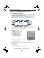
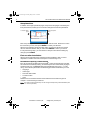
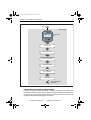
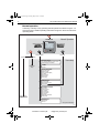
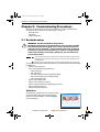
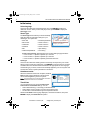
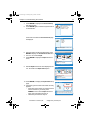
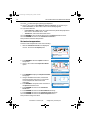
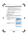
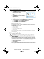
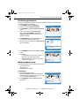
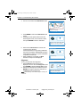
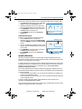
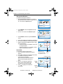
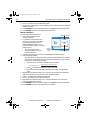
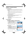
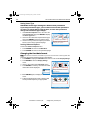
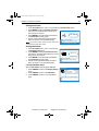
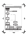
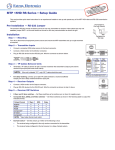
81284_1.book Page 1 Friday, May 4, 2007 7:29 AM
ST70 Instrument
User Reference
Manual
Document reference: 81284-1
Date: June 2007
www.Busse-Yachtshop.de
[email protected]
81284_1.book Page 2 Friday, May 4, 2007 7:29 AM
Raymarine, SeaTalk, SeaTalk2 and SeaTalkng are trademarks of Raymarine plc
© Book contents copyright Raymarine plc
www.Busse-Yachtshop.de
[email protected]
81284_1.book Page i Friday, May 4, 2007 7:29 AM
Contents
i
Contents
Preface ........................................................................................................................... iii
Safety notices ..........................................................................................................iii
WARNING: Product installation & operation .................................. iii
WARNING: Electrical safety................................................................. iii
WARNING: Navigational safety ........................................................... iii
EMC conformance ...................................................................................................iii
Certified installation ..................................................................................................iii
Product documents ..................................................................................................iii
Product disposal ......................................................................................................iv
Waste Electrical and Electronic (WEEE) Directive ...................................iv
Chapter 1:ST70 General Information ................................................................... 1
1.1 ST70 Operating Principles ............................................................................. 1
Controls.......................................................................................................... 1
Setup functions............................................................................................... 2
First use after installation ................................................................................ 2
Instruments requiring commissioning ......................................................... 2
Instruments not requiring commissioning ................................................... 3
Normal operation............................................................................................ 4
Day-to-day setting up...................................................................................... 5
1.2 System functionality ....................................................................................... 5
SeaTalk .......................................................................................................... 5
SeaTalk2 & SeaTalkng .................................................................................................................................... 5
Power protocol ............................................................................................... 6
1.3 Commissioning requirement .......................................................................... 6
WARNING: Product installation & operation .................................. 6
Chapter 2:Commissioning Procedures ................................................................ 7
2.1 Dockside setup .............................................................................................. 7
WARNING: Product installation & operation .................................. 7
Switch on........................................................................................................ 7
Initial setup ..................................................................................................... 8
Select language .......................................................................................... 8
Vessel Type ................................................................................................ 8
Select type ................................................................................................ 8
Autodetect results ....................................................................................... 8
Time & Date................................................................................................ 8
Setting date format ................................................................................... 9
Setting time format .................................................................................... 9
Setting local time .................................................................................... 10
Leaving date & time setup ....................................................................... 10
Data units.................................................................................................. 10
Leaving units setup ................................................................................. 11
Depth offset ...................................................................................................11
WARNING: Ensure you use the correct depth offset ................. 12
Requirement ............................................................................................. 12
Depth offset setup procedure ................................................................... 12
Set water temperature .................................................................................. 14
Set ground wind............................................................................................ 15
Set magnetic variation .................................................................................. 15
Changing response rate ............................................................................... 16
Ending dockside setup.................................................................................. 17
www.Busse-Yachtshop.de
[email protected]
81284_1.book Page ii Friday, May 4, 2007 7:29 AM
ii
ST70 Instrument User Reference Manual
2.2 Seatrial calibration ....................................................................................... 17
WARNING: Ensure you have sufficient sea room for calibration17
Preliminary procedures................................................................................. 18
Wind transducer setup.................................................................................. 18
Linearization ............................................................................................. 18
Alignment .................................................................................................. 19
Calibrate wind speed ................................................................................ 20
Speed calibration .......................................................................................... 20
Start speed calibration .............................................................................. 21
Set to SOG ............................................................................................... 21
Manual calibration..................................................................................... 22
2.3 Return to normal operation .......................................................................... 23
2.4 After commissioning .................................................................................... 23
EMC Conformance ....................................................................................... 23
Chapter 3:Setup Procedures ................................................................................. 25
3.1 Introduction .................................................................................................. 25
3.2 Procedures .................................................................................................. 25
Changing the language or vessel type setting............................................... 25
Setting Language...................................................................................... 25
Setting Vessel Type .................................................................................. 26
CAUTION: Vessel Type setting also affects other parameters ... 26
Leaving Advanced Options ....................................................................... 26
Changing the time/date format...................................................................... 26
Setting time format.................................................................................... 27
Setting date format ................................................................................... 27
Leaving time/date setup............................................................................ 27
Chapter 4:Maintenance & Troubleshooting ..................................................... 29
4.1 Maintenance ................................................................................................ 29
Servicing and safety ..................................................................................... 29
Instrument Cleaning ..................................................................................... 29
Cabling ......................................................................................................... 29
4.2 Troubleshooting ........................................................................................... 30
First considerations ...................................................................................... 30
Procedures ................................................................................................... 30
Using About Display feature ......................................................................... 33
Technical support.......................................................................................... 34
World wide web ........................................................................................ 34
Telephone help line .................................................................................. 35
Help us to help you ................................................................................... 35
Specification............................................................................................................... 37
Glossary ....................................................................................................................... 39
Index.............................................................................................................................. 41
www.Busse-Yachtshop.de
[email protected]
81284_1.book Page iii Friday, May 4, 2007 7:29 AM
Preface
iii
Preface
Contents
Safety notices
WARNING: Product installation & operation
This equipment must be installed, commissioned and operated in
accordance with the Raymarine instructions provided. Failure to
do so could result in personal injury, damage to your boat and/or
poor product performance.
WARNING: Electrical safety
Make sure you have switched off the power supply before you start
installing this product.
WARNING: Navigational safety
Although we have designed this product to be accurate and
reliable, many factors can affect its performance. Therefore, it
should serve only as an aid to navigation and should never replace
commonsense and navigational judgement. Always maintain a
permanent watch so you can respond to situations as they
develop.
EMC conformance
All Raymarine equipment and accessories are designed to the best industry
standards for use in the recreational marine environment.
The design and manufacture of Raymarine equipment and accessories conform to
the appropriate Electromagnetic Compatibility (EMC) standards, but correct
installation is required to ensure that performance is not compromised.
Certified installation
Raymarine recommends certified installation by a Raymarine approved installer. A
certified installation qualifies for enhanced warranty benefits. Contact your
Raymarine dealer for further details and refer to the separate warranty document
packed with your product.
Product documents
The following user documents are available for ST70:
• ST70 Operating Guide. Comprises a series of individual operating cards, which
provide day-to-day operating and setting up procedures. Intended for all users.
• ST70 User Reference Manual (this document). Intended for users in general and
commissioning personnel in particular. It describes:
• Commissioning procedures. These describe how to set up an ST70 instrument when first switched on after installation.
• Setup procedures not included in the Operating Guide
www.Busse-Yachtshop.de
[email protected]
81284_1.book Page iv Friday, May 4, 2007 7:29 AM
iv
ST70 Instrument User Reference Manual
• Routine maintenance instructions
• Troubleshooting instructions
• ST70 Installation Guide. Describes how to fit an ST70 instrument and connect it to
an operating system. Intended for installers.
Additional information on Raymarine SeaTalkng systems is given in the SeaTalkng
Reference Manual.
To the best of our knowledge, the information in the product documents was correct
when they went to press. However, Raymarine cannot accept liability for any
inaccuracies or omissions in product documents.
In addition, our policy of continuous product improvement may change specifications
without notice. Therefore, Raymarine cannot accept liability for any differences
between the product and the accompanying documents.
Product disposal
Waste Electrical and Electronic (WEEE) Directive
The WEEE Directive requires the recycling of waste electrical and electronic
equipment.
Whilst the WEEE Directive does not apply to some of Raymarine's products,
we support its policy and ask you to be aware of how to dispose of this product.
The crossed out wheelie bin symbol, illustrated above, and found on our products
signifies that this product should not be disposed of in general waste or landfill.
Please contact your local dealer, national distributor or Raymarine Technical Services
for information on product disposal.
www.Busse-Yachtshop.de
[email protected]
81284_1.book Page 1 Friday, May 4, 2007 7:29 AM
Chapter 1: ST70 General Information
1
Chapter 1: ST70 General Information
1.1 ST70 Operating Principles
The ST70 instrument repeats data from Raymarine SeaTalk, SeaTalk2 and SeaTalkng
systems. The actual information available depends on what information is present on
the system, i.e. what transducers are connected.
The ST70 instrument displays information on individual operational pages. Eight
pages are available, and you can scroll from page to page by using the and
buttons.
Page 6
Page 7
Page 8
Depth
Speed
Heading
o
9.0ft 7.kts
0 63
xx
Page 1
Lon
47No 47
CANCEL
Time
11:23
24H
D9262-1
Page 5
Lat
ENTER
MENU
Page 4
Page 3
Page 2
An operational page can comprise from one to six individual data frames. You can set
up the layout of each page by selecting one of sixteen inbuilt page layouts then
defining the data content of each frame on the page.
Controls
and buttons. Used to:
Scroll to different operating pages.
Select choices on setup pages
< and > buttons. Used to:
• Scroll to different menu options.
• Set values on setup pages.
• Select choices on setup pages.
MENU button. Gives access to:
• All setup and reset functions.
• Self test routines and diagnostic information.
ENTER button. Used during setup procedures to:
• Confirm a menu selection
Power button
• Save a setting and continue
CANCEL button. Used during setup procedures to leave a setup function without
making any changes.
Power button
:
• Switches power on and off.
• Provides access to screen brightness control.
•
•
ENTER
MENU
www.Busse-Yachtshop.de
[email protected]
D9447-1
CANCEL
81284_1.book Page 2 Friday, May 4, 2007 7:29 AM
2
ST70 Instrument User Reference Manual
Setup functions
In addition to the eight operational pages, setup menus and pages controlled by the
front-panel buttons, enable you to access and change the instrument parameters.
To choose option 1
press
Menu Title
1
To choose option 3
press
2
3
Selected option
Information box
Press ENTER to select
D10031-1
i
Each setup menu provides a number of options. Use the < and > buttons to scroll to
the menu item you want, then press ENTER to confirm your selection.
When a menu selection results in a setup page, use the < and > buttons to set the
value or make the selection that you want. Press ENTER to confirm your choice.
If at any time during setup, you want to leave a setup function without making any
changes, press CANCEL.
First use after installation
When an ST70 instrument is first switched on after installation, what you see is
dependent on whether the instrument requires commissioning or not.
Instruments requiring commissioning
If the ST70 instrument is NOT part of a SeaTalkng system in which at least one other
ST70 instrument is already working, an initial setup mode is automatically engaged
and at first switch on, a Language setup page is displayed (see Figure 1-1: Initial
setup). This is the first part of the commissioning procedure and enables you to set:
• Language.
• Vessel type.
• Time and date formats.
• Local time value.
• Units.
Details of how to set these values and commission the instrument are given in
Chapter 2: Commissioning Procedures.
Note: The values set during initial setup can be changed subsequently via the Main Menu (see
Figure 1-2: Normal operation).
www.Busse-Yachtshop.de
[email protected]
81284_1.book Page 3 Friday, May 4, 2007 7:29 AM
Chapter 1: ST70 General Information
3
First switch on
Hold down
Initial setup
POWER ON
Language
Language select
page
English (UK)
Press ENTER to select
CANCEL
ENTER
MENU
ENTER
Welcome page
ENTER
SELECT BOAT TYPE
ENTER
TIME & DATE SUMMARY
ENTER
TIME & DATE SETUP
ENTER
UNITS SUMMARY
ENTER
UNITS SETUP
ENTER
To normal operation
(Figure 1-2)
D9777-1
Figure 1-1: Initial setup
Instruments not requiring commissioning
If the ST70 instrument is part of a SeaTalkng system in which at least one other ST70
instrument is already working, then an operational page is displayed at initial switch
on and you can use the instrument immediately. In this case, the new instrument will
adopt the settings that already apply in the system.
www.Busse-Yachtshop.de
[email protected]
81284_1.book Page 4 Friday, May 4, 2007 7:29 AM
4
ST70 Instrument User Reference Manual
Normal operation
A summary of the day-to-day operating and setup functions is shown in Figure 1-2:
Normal operation. Detailed operating instructions are given in the ST70 Instrument
Operating Guide.
Hold down
Normal Operation
POWER ON
Select previous page
Page displayed at
switch on, is same
as when intrument
last switched off
CANCEL
Select next page
ENTER
MENU
MENU
ENTER
Press & release
Hold down
Hold down
Press & release
User setup
Reset data pages
Only resettable data types on the current
operational page are available.
Brightness
setup
ALARMS
Edit alarm
DISPLAY SETTINGS
Time & Date setup*
Brightness setup
Colors (day/night options)
Units setup*
Response setup
Rollover setup
Timers setup
PAGE LAYOUT
Turn page on/off
Rebuild page from new
Change data
ADVANCED OPTIONS
Count down to
Setup Wizard
Transducer Setup
Set Language*
Set Vessel Type*
Set Ground Wind
Set Variation
Select Boat Show Mode
Factory Reset
POWER OFF
DIAGNOSTICS
About Display
Self Test
* also part of initial setup
D9776-1
Figure 1-2: Normal operation
www.Busse-Yachtshop.de
[email protected]
81284_1.book Page 5 Friday, May 4, 2007 7:29 AM
Chapter 1: ST70 General Information
5
Day-to-day setting up
Instructions for setting up many of the ST70 Instrument parameters are given in the
ST70 Instrument Operating Guide and are not repeated here. Other setup
procedures are carried out during Commissioning to set:
• Language.
• Vessel Type.
• Time format.
• Date format.
• Method used for ground wind calculation
• Magnetic variation
• Response rate
If you need to change any of these after the instrument has been commissioned, refer
to the appropriate procedure in Chapter 3: Setup Procedures.
1.2 System functionality
Your ST70 instrument is fitted with Raymarine SeaTalkng connectors, but it can be
connected to any of the following Raymarine systems, using suitable adaptor cables
as necessary:
• SeaTalk
• SeaTalk2
• SeaTalkng
SeaTalk
When connected to a SeaTalk system, each ST70 instrument repeats the SeaTalk
data. You can set the system variation only if it has not been set at another product.
You cannot set the data units or calibrate the system transducers.
SeaTalk2 & SeaTalkng
When connected to a SeaTalk2 & SeaTalkng system, each ST70 instrument repeats
the data on the bus. You can set the instrument response as required. You can set the
system variation only if it has not been set at another product.
You can also calibrate the system transducers and set the data units you want to apply
to the system.
www.Busse-Yachtshop.de
[email protected]
81284_1.book Page 6 Friday, May 4, 2007 7:29 AM
6
ST70 Instrument User Reference Manual
Power protocol
Power to each individual ST70 instrument can be switched on and off using the power
button
(as described in the ST70 Operating Guide). However, where instruments
are part of a system, it may be more convenient to switch power for the entire system
from a central circuit breaker.
In this case, when system power is switched ON again:
• ST70 instruments that were switched on when power was last switched off will
return to the switched ON state.
• ST70 instruments that were OFF when system power was last switched OFF will
remain OFF and will need to be switched ON individually using their power buttons.
1.3 Commissioning requirement
WARNING: Product installation & operation
Each ST70 instrument must be prepared for use in accordance with the
Commissioning Procedures, before it is used for operational purposes,
unless it is part of a SeaTalkng system in which at least one other ST70
instrument is already set up and working, it. Failure to comply with this
could result in death, personal injury, damage to your boat and/or poor
product performance.
After installation, each ST70 instrument that is NOT part of a SeaTalkng system in
which at least one other ST70 instrument is already set up and working must be
commissioned in accordance with Chapter 2: Commissioning Procedures, before it is
used for operational purposes.
Note: if an instrument is part of a system in which at least one other ST70 instrument is already
set up and working, you do not need to commission it.
Refer to the ST70 Instrument Operating Guide for instructions on how to use the ST70
instrument on a day-to-day basis.
www.Busse-Yachtshop.de
[email protected]
81284_1.book Page 7 Friday, May 4, 2007 7:29 AM
Chapter 2: Commissioning Procedures
7
Chapter 2: Commissioning Procedures
Before an ST70 instrument is used for the first time, it must be commissioned in
accordance with the instructions in this chapter, to carry out:
• Dockside setup
followed by
• Seatrial calibration.
2.1 Dockside setup
WARNING: Product installation & operation
Each ST70 instrument must be prepared for use in accordance with the
Commissioning Procedures, before it is used for operational purposes,
unless it is part of a SeaTalkng system in which at least one other ST70
instrument is already set up and working, it. Failure to comply with this
could result in death, personal injury, damage to your boat and/or poor
product performance.
Notes:
If your ST70 instrument is connected to an existing SeaTalkng system that has
already been successfully commissioned, you do not need to commission the
new instrument.
(2) Values set during Dockside setup can be changed subsequently, if necessary.
(1)
Use these Dockside setup instructions when an ST70 instrument is first started after
installation to:
• Switch on the instrument.
• Carry out the initial setup procedures, to:
• Select language.
• Set vessel type.
• Set date and time format (only if GPS is fitted).
• Set correct local time (only if GPS is fitted).
• Set required data units.
• Set the correct depth offset.
• Set the correct magnetic variation.
• Set the required method for calculating ground wind.
• Set the water temperature.
• Set the instrument response.
Switch on
Hold down the power button for 1 second to power
up the instrument. When the instrument is first
switched on after installation, a select Language
menu is displayed.
Language
Press ENTER to select
www.Busse-Yachtshop.de
[email protected]
D9342-1
English (UK)
81284_1.book Page 8 Friday, May 4, 2007 7:29 AM
8
ST70 Instrument User Reference Manual
Initial setup
Select language
Use < and > to select the required language, then press ENTER to display the
‘Welcome’ screen. When you are ready to proceed, press ENTER to display the
Vessel Type menu.
Vessel Type
Vessel Type
The Vessel Type menu enables you to automatically
apply the optimum instrument settings for your
vessel type. The options are:
• Race Sail
• Inboard Speed Boat
• Power Cruiser 1*
• Catamaran
• Power Cruiser 2*
• Workboat
• Power Cruiser 3*
• RIB
• Sport Fishing
• Outboard Speed Boat
• Pro Fishing
Inboard Speed Boat
Selecting vessel type helps us to
i configure your system.
Press ENTER to select
D10092-1
• Sail Cruiser
*Power Cruiser settings. Note that the Power Cruiser settings apply as follows:
• Power Cruiser 1 - capable of speeds up to 12 knots.
• Power Cruiser 2 - capable of speeds up to 30 knots.
• Power Cruiser 3 - capable of speeds greater than 30 knots.
Select type
Use < and > to select the vessel type that most closely corresponds to your vessel.
When you have chosen the vessel type, press ENTER to confirm the choice. The Time
and Date values and the data Units considered most appropriate for the Language
and Vessel Type you chose, are then automatically applied to your ST70 system and
an automatic check of system parameters is carried out.
Autodetect results
Time & Date
Time
11:01:03
Date
14/06/07
Time Offset
-1 Hrs
Time Format
24-hour
Date Format dd/mm/yy
Note: If your instrument is not receiving GPS information,
time and date information are not available.
Time & Date
i
These are your current settings.
You can either change or accept the Date Format,
Press ENTER to continue
Time Format and Time Offset settings. You can:
• Select either dd/mm/yy or mm/dd/yy as the date format
• Select either 12-hour (am/pm) or 24-hour as the time format.
• Set the value of the time offset to give the required local time.
With the Time & Date summary page displayed, check the information, then press
ENTER to display the Time & Date setup menu.
www.Busse-Yachtshop.de
[email protected]
D9424-1
When the automatic checks are complete, a Time &
Date summary page is displayed. This shows the
current values applied to your ST70 system.
81284_1.book Page 9 Friday, May 4, 2007 7:29 AM
Chapter 2: Commissioning Procedures
9
Setting date format
To set the required date format:
1. At the Time & Date setup menu, use < and > to
select the Set date format option, then press
ENTER, to display the Set date format page.
Time & Date
Press ENTER to select
Time & Date
Set date format
Press ENTER to select
2. Use < and > to select the required Date Format,
then press ENTER, to save the format and
return to the Time & Date summary page.
3. Press ENTER to select the Time & Date setup
menu.
D9982-1
Continue
D9544-1
If you want to accept the Time & Date values:
1. Select the Continue option (if necessary use <
or >).
2. Press ENTER to proceed to the Units summary
page.
3. Proceed from Data units (below).
If you want to change any Time & Date values, carry
out the Setting date format, Setting time format
and/or Setting local time procedure below, as
appropriate.
Set date format
dd/mm/yy
< & > to adjust.
Setting time format
To set the required time format:
1. With the Time & Date setup menu displayed,
use < and > to select the Time Format option,
then press ENTER, to display the Set time
format page.
Press ENTER to accept
D9542-1
i CANCEL exits without saving.
Time & Date
Press ENTER to select
2. Use < and > to select the required Time Format,
then press ENTER, to save the format and
return to the Time & Date summary page.
3. Press ENTER to select the Time & Date setup
menu.
D10362-1
Set time format
Set time format
12-hour
Use < & >to adjust.
Press ENTER to accept
www.Busse-Yachtshop.de
[email protected]
D9779-1
i CANCEL exits without saving.
81284_1.book Page 10 Friday, May 4, 2007 7:29 AM
10
ST70 Instrument User Reference Manual
Setting local time
To set the instrument time to your local time.
1. At the Time & Date setup menu, use < and > to
select the Set time offset option, then press
ENTER, to display the Set time offset page.
Time & Date
Press ENTER to select
2. Use < and > to set the correct local time. For
example, if your local time is 1 hour after GMT,
set -1, then press ENTER, to save the setting
and return to the Time & Date setup menu.
3. Press ENTER to select the Time & Date setup
menu.
D9421-1
Set time offset
Set time offset
-1.0
hrs
Use < & > to adjust.
Press ENTER to accept
Leaving date & time setup
When your date and time formats and values are set as required:
1. Display the Time & Date setup menu.
2. Use < and > to select the Continue option.
3. Press ENTER, to proceed to the Units summary.
D9549-1
i CANCEL exits without saving.
Data units
D9439-1
The Units summary comprises two pages and shows units currently in use. You can
accept all or change any of the data Units settings. You can set:
• Speed to either miles per hour, kilometers per hour or knots.
• Distance to either miles, nautical miles or
Units
kilometers.
Speed
KTS
Distance
NM
• Depth to either feet, fathoms or meters.
Depth
FT
Wind
Speed
KTS
• Wind speed to either knots or meters per
Heading
M
second.
Flow Rate
G/H
o
Temperature
C
• Heading to either magnetic or true.
These are your current settings.
i
• Flow rate to either US gallons per hour, UK
gallons per hour or liters per hour
Press ENTER to continue
• Temperature to degrees Celsius or degrees
Fahrenheit.
• Pressure to pound per square inch or kiloPascals.
• Volume to either US gallons, UK gallons or liters
• Number of engines to either 1, 2, 3, 4 or 5.
• Number of batteries to either 1, 2, 3, 4 or 5.
• Number of fuel tanks to either 1, 2, 3, 4 or 5.
Press ENTER to see the second Units summary page, and if you want to return to the
first page from the second, press CANCEL.
www.Busse-Yachtshop.de
[email protected]
81284_1.book Page 11 Friday, May 4, 2007 7:29 AM
Chapter 2: Commissioning Procedures
11
Check the information on the Units summary pages.
With the second Units summary page displayed, press ENTER to display the Units
setup menu.
Units
Continue
Press ENTER to select
If you want to change any data Units:
1. With the Units setup menu displayed, use < and
> to select the type of data you want to change,
i.e. Speed, Depth, Distance etc.
D9980-1
If you want to accept all data Units as currently set:
1. Select the Continue option (if necessary use <
or >).
2. Press ENTER, to leave Initial Setup and
proceed to the first operational page.
3. Proceed from Depth offset (below).
Units
Press ENTER to select
Wind Speed Units
KTS
Use < & > to adjust.
i CANCEL exits without saving.
Press ENTER to accept
D9442-1
2. Press ENTER, to display the setup page for the
units you have selected.
3. Use < and > to select the required units
4. Press ENTER, to save the units setting and
return to the first Units summary page.
5. Press ENTER twice to display the Units setup
menu
6. If you want to change any other units, repeat
steps 1 to 5 of this procedure.
D9441-1
Wind Speed Units
Leaving units setup
When all units are set to what you want, display the Units setup menu, then:
1. Use < and > to select the Continue option.
2. Press ENTER, to leave Initial Setup and proceed to the first operational page.
Depth offset
Depths are measured from the Depth transducer to the sea bed, but you can apply an
offset value to the depth data, so that the displayed depth reading represents the
depth to the sea bed from either the keel or the water line.
If an offset is not applied, the displayed depth readings are from the transducer to the
sea bed.
www.Busse-Yachtshop.de
[email protected]
81284_1.book Page 12 Friday, May 4, 2007 7:29 AM
12
ST70 Instrument User Reference Manual
WARNING: Ensure you use the correct depth offset
The use of the correct depth offset is critical to the safety of the vessel.
If an incorrect offset value is applied, this could result in misleading
depth information being displayed with a consequent risk of running
aground. Take great care to ensure you set the correct value.
Requirement
If you want to apply an offset to your depth readings, you MUST set the correct offset
value, before relying on Depth data.
Therefore, before attempting to set a waterline or keel offset, find out the vertical
separation between the transducer and either the waterline or the bottom of the keel
on your vessel, as appropriate. See Figure 2-1.
Waterline
offset
Offset value
of 0.0
Keel
offset
D9343-1
Figure 2-1 Depth offsets
Depth offset setup procedure
Advanced Options
Transducer Setup
Press ENTER to select.
www.Busse-Yachtshop.de
[email protected]
D9780-1
To set the correct depth offset:
1. With any operational page displayed, press
MENU to display the Main Menu.
2. Use < or > to scroll to Advanced Options, then
press ENTER
3. At the Advanced Options menu, use < or > to
scroll to Transducer Setup.
81284_1.book Page 13 Friday, May 4, 2007 7:29 AM
Chapter 2: Commissioning Procedures
13
Transducer Setup
ST70 will now search
the network for
transducers. Press
CANCEL to stop.
Press ENTER to continue
At the end of the search a Search Results page
is displayed.
D10359-1
4. Press ENTER to display the Transducer Setup
start search page.
5. Press ENTER again, to initiate a system search
for transducers.
Search Results
Found:
1 Depth
1 Speed
1 Wind
If not correct, press CANCEL and
Press ENTER to continue
6. With the search results page displayed, press
ENTER to display the Transducers found menu.
7. Use < or > to scroll to Depth.
8. Press ENTER to display the Depth transducer
menu.
D10064-1
i check connections.
Transducers found
Depth
Press ENTER to select.
9. With the Depth transducer menu displayed, use
< or > to scroll to the Depth Offset option.
D9781-1
Raymarine
i Serial no. 100020
Depth
i
Verdana
6.5 pt
Raymarine
Serial no. 100020
Press ENTER to select
www.Busse-Yachtshop.de
Depth Offset
Keel
2.5
ft
Warning! Incorrect offset may
i
lead to vessel running aground.
Press ENTER to accept
[email protected]
D9782-1
10. Press ENTER, to display the Depth Offset setup
page.
11. Check the type and value of the offset currently
applied:
• If the offset type is what you require and the
value is correct for your boat, press
CANCEL to return to the Depth transducer
menu, then proceed from step 16.
• Otherwise proceed from step 12.
D10056-1
Depth Offset
81284_1.book Page 14 Friday, May 4, 2007 7:29 AM
14
ST70 Instrument User Reference Manual
12. Press to select the upper (offset type) adjust box.
13. Use < or > to scroll to either Water line, Keel or Transducer, as required. If you
select Transducer, an offset value of zero is automatically applied.
14. If you have selected:
• Either Water line or Keel, press to select the lower (offset value) adjust box
then use < or > to set the correct value.
• Transducer, ensure the offset value is zero.
15. Press ENTER to save the offset value return to the Depth transducer menu.
16. Press CANCEL to return to the Transducers found menu.
Now proceed to Set water temperature .
Set water temperature
To set the water temperature to the correct reading:
1. With the Transducers Found menu displayed,
use < or > to scroll to the Speed option.
Transducers Found
Speed
Press ENTER to select.
2. Press ENTER to select the Speed transducer
setup menu.
3. Use < or > to scroll to the Temperature Offset
option.
D10080-1
Raymarine
i Serial no. 100031
Speed
Raymarine
Serial no. 100031
Press ENTER to select.
4. Press ENTER to display the Temperature Offset Temperature Offset
setup page.
5. Using a suitable thermometer, measure the
7
water temperature, then use < or > to set the
°C
correct temperature value at the ST70
instrument.
Adjust temperature until reads
6. Press ENTER to accept the value and return to
i actual sea temperature
the Speed transducer menu.
Press ENTER to accept
7. Press CANCEL to return to the Transducers
found menu.
8. Press CANCEL to return to the Search Results summary.
9. Press CANCEL to return to the Transducer Setup start page.
10. Press CANCEL to return to the Advanced Options menu.
Now proceed to Set ground wind
www.Busse-Yachtshop.de
[email protected]
D10094-1
i
D10093-1
Temperature Offset
81284_1.book Page 15 Friday, May 4, 2007 7:29 AM
Chapter 2: Commissioning Procedures
15
Set ground wind
You can choose either Speed Over Ground (SOG) or Speed Through Water (STW)
from which to derive the ground wind speed.
To set the required method:
Advanced Options
1. With the Advanced Options menu displayed,
use < or > to select the Ground Wind option.
Press ENTER to select
Ground Wind
SOG
Select data source for Ground Wind.
i
Set magnetic variation
Press ENTER to accept
D10057-1
2. Press ENTER, to display the Ground Wind setup
box.
3. Use < or > to select either STW or SOG, then
press ENTER to return to the Advanced Options
menu.
Now proceed to Set magnetic variation .
D9301-1
Ground Wind
The magnetic variation is the difference in heading
between true north and magnetic north. Before setting this, refer to an up-to-date
chart of the area in which you intend using your boat, to ascertain the correct value of
magnetic variation.
Note: As the magnetic variation is dependent on your geographical location, you may need to
change the magnetic variation value during a long voyage.
To set the magnetic variation:
1. With the Advanced Options menu displayed,
use < or > to select the Variation option.
Advanced Options
Press ENTER to select
2. Press ENTER, to display the Variation setup
box. This has two adjust boxes, an upper box
which shows the variation mode, and a lower
box that shows the variation value.
3. Press to select the upper (mode) adjust box.
D10091-1
Variation
Variation
On
-6
i
Set difference between Magnetic
and True bearings.
Press ENTER to accept
www.Busse-Yachtshop.de
[email protected]
D10058-1
degrees
81284_1.book Page 16 Friday, May 4, 2007 7:29 AM
16
ST70 Instrument User Reference Manual
4. Use < or > to select the required mode:
• Select ON if you want to set a value for variation. if you choose this mode, the
value you set will be applied to the rest of the system.
• Select OFF if you do not want to apply a variation value to the system.
• If SLAVE is displayed in the mode adjust box, the variation has been set at
another product in the system, and the value is shown in the lower adjust box.
In this mode, you cannot change the variation value.
5. If you selected the OFF or SLAVE mode, proceed from step 6. If you selected the
ON mode:
i. Press to select the lower (value) box.
ii. Use < or > to set the correct variation value.
6. Press ENTER to save the value and return to the Advanced Options menu.
7. Press CANCEL to return to the Main Menu.
Now proceed to Changing response rate .
Changing response rate
The response setting determines the rate at which data readings update. You can
adjust the response at each instrument, to best suit the conditions under which you
are operating. You can independently adjust the response at each instrument, for
individual data types.
If you want to change the response at any instrument:
1. With the Main Menu displayed, use < or > to scroll to Display Settings.
2. Press ENTER to display the Display Settings
Display Settings
menu.
3. At the Display Settings menu, use < or > to scroll
to the Response option.
Response
Select display response
Press ENTER to select
4. Press ENTER to display the Response menu,
then use < or > to scroll to the required data type
(Speed shown here).
D10088-1
i
Response
Press ENTER to select.
www.Busse-Yachtshop.de
[email protected]
D10090-1
Speed
81284_1.book Page 17 Friday, May 4, 2007 7:29 AM
17
5. Press ENTER to display the response adjust box Speed
for the data you have selected.
6. Use < or > to set the response rate. A higher
12
value gives a quicker response rate and vice
versa.
7. Press ENTER to save the value and return to
< & > adjust response level.
the Response menu.
i CANCEL exits without saving
8. If you want to change the response for other
Press ENTER to accept
data types, use < or > to scroll to the required
data type, then repeat steps 5 to 8.
9. To leave response setup, ensure the Response menu is displayed, then:
i. Press CANCEL to return to the Display Settings menu.
ii. Press CANCEL to return to the Main Menu.
iii. Press CANCEL to return to the operational page.
D10089-1
Chapter 2: Commissioning Procedures
Ending dockside setup
Dockside setup is complete when you have satisfactorily carried out the initial setup
procedures and correctly set the:
• Depth offset.
• Water temperature.
• Magnetic variation.
• Ground wind calculation method.
• Response rate.
When Dockside setup is complete, return to the operational page, then carry out a
Seatrial calibration.
2.2 Seatrial calibration
WARNING: Ensure you have sufficient sea room for calibration
The seatrial calibration maneuvers require a sufficiently clear area of
water. Ensure you are not likely to collide with any vessel or obstruction
during calibration.
When the dockside calibration procedures are complete, navigate to a place where
you have plenty of sea room then carry out the seatrial calibration procedures. These
set the ST70 instrument so it gives an optimum performance with the system
transducers. The seatrial calibration comprises:
• Wind calibration & alignment.
• Speed calibration.
When you have completed the appropriate seatrial procedures, proceed to Return to
normal operation.
www.Busse-Yachtshop.de
[email protected]
81284_1.book Page 18 Friday, May 4, 2007 7:29 AM
18
ST70 Instrument User Reference Manual
To carry out any seatrial calibration procedure, switch on the instrument, then when
an operational page is displayed:
1. Press MENU to select the Main Menu.
Advanced Options
2. Use < or > to select Advanced Options.
3. Press ENTER to display the Advanced Options
menu
4. Use < or > to select the Transducer Setup
Transducer Setup
option, then press ENTER, to display the
Transducer Setup screen showing a search
initiation message.
Press ENTER to select.
5. Press ENTER again, to initiate a search for
transducers connected to the system.
When the search is complete, a Search Results
page is displayed.
D9780-1
Preliminary procedures
Search Results
Found:
1 Depth
1 Speed
1 Wind
If not correct, press CANCEL and
Press ENTER to continue
Wind transducer setup
Transducers found
Depth
Raymarine
i Serial no. 100020
Press ENTER to select.
D9781-1
6. Press ENTER to display the Transducers found
menu.
7. If you have:
• A Wind transducer, carry out the Wind
transducer setup procedure below.
• A Speed transducer, carry out the Speed
calibration on page 20.
D10064-1
i check connections.
The wind transducer setup procedures are used to:
• Linearize the vane.
• Align the vane.
• Calibrate the wind speed.
Linearization
Transducers found
Wind
Raymarine
i Serial no. 100030
Press ENTER to select.
www.Busse-Yachtshop.de
[email protected]
D9783-1
1. To linearize the wind vane:.
1. With the Transducers found menu displayed
(see Preliminary procedures on page 18), use
< or > to scroll to the Wind option
2. Press ENTER to select the Wind transducer
setup menu.
81284_1.book Page 19 Friday, May 4, 2007 7:29 AM
Chapter 2: Commissioning Procedures
19
3. Use < or > to scroll to the Calibrate Vane option.
Wind
Press ENTER to select.
4. Press ENTER to select the Calibrate Vane start
screen.
5. Keeping the boat speed below 2 knots and
observing the screen, turn the boat in circles,
then press ENTER to start the calibration.
D10061-1
Calibrate Vane
Raymarine
i Serial no. 100030
Calibrate Vane
Press ENTER to continue
Calibrate Vane
35%
i
Keep turning....
Press CANCEL to stop
D10322-1
6. Observe the Calibrate Vane run screen and
continue turning the boat.
If the boat speed is too high during calibration,
the instrument displays a Slow down message.
If this happens, reduce your speed. Calibration
completes automatically.
7. When calibration is complete, the Wind
transducer setup menu is displayed.
D10060-1
Move in a slow circle, below 2Kts.
i Watch for 'too fast' on display.
Alignment
Note: On a calm day, motor fast enough to create ‘your
own wind’.
www.Busse-Yachtshop.de
Align Vane
AWA 105° P
Steer your boat directly into the
i wind, then press ENTER.
Press ENTER to accept
[email protected]
D10073-1
To carry out the wind vane alignment:
1. With the Wind transducer setup menu
displayed, use < or > to scroll to Align Vane, then
press ENTER to display the Align Vane screen
2. Sail the boat directly into the wind, then press
ENTER to accept the alignment and return to
the Wind transducer setup menu.
81284_1.book Page 20 Friday, May 4, 2007 7:29 AM
ST70 Instrument User Reference Manual
If there is any inaccuracy after you have completed the Align Vane procedure, then:
1. At the Wind transducer setup menu, select Vane Vane Adjust
Adjust, to display the Vane Adjust screen.
2. Sail the boat directly into the wind, then use <
15°
and > to manually set the wind reading to zero.
3. Press ENTER to accept the value and return to
the Wind transducer setup menu.
Manually adjust your vane offset.
i
4. Press CANCEL to return to the Transducers
AWA 105° P
found menu.
Press ENTER to accept
D10079-1
20
Calibrate wind speed
Calibration factor
Calibrate AWS
0.73
i
See Docs for Manual Calibration.
AWS: 3.2 KTS
ess
D10366-1
To set the correct apparent wind speed reading:
1. With the Wind transducer setup menu
displayed, use < or > to scroll to Calibrate AWS,
then press ENTER to display the Calibrate AWS
screen.
2. Use < or > to adjust the Calibration Factor so that
the AWS value in the information box is set to the
correct value.
3. Press ENTER to accept the value and return to
the Wind transducer setup menu.
4. Press CANCEL to return to the Transducers
found menu.
AWS value
Speed calibration
The object of speed calibration is to ensure that the speed readings at the ST70
instruments are true indications of the boat speed, ideally over the speed range of the
vessel, i.e. from stationary to top speed.
In order to take into account the changes in water-flow characteristics across the hull,
for different speeds, it is advisable carry out speed calibration at as many speeds as
possible, up to the maximum of five, provided by ST70. This is particularly
important for planing vessels.
The correct calibration at each speed is achieved by applying a calibration factor to
the indicated speed reading. The correct value for the calibration factor is obtained by
one of two methods:
• If SOG information is available, you can use this as a reference, to enable you to
set the correct calibration factor.
• If SOG information is not available, you need to manually calculate and apply the
correct calibration factor.
In order to achieve accurate results, speed calibration must be carried out in
conditions of zero tide and zero current.
Carry out the Start speed calibration procedure (page 21) followed by the Set to SOG
or Manual calibration procedure, as required.
www.Busse-Yachtshop.de
[email protected]
81284_1.book Page 21 Friday, May 4, 2007 7:29 AM
Chapter 2: Commissioning Procedures
21
Start speed calibration
To calibrate the Speed transducer:
1. With the Transducers Found menu displayed
(see Preliminary procedures on page 18), use
< or > to scroll to the Speed option.
Transducers Found
Press ENTER to select.
2. Press ENTER to select the Speed transducer
setup menu.
3. Use < or > to scroll to the Calibration option.
D10080-1
Speed
Raymarine
i Serial no. 100031
Speed
Calibration
Calibration
2 KTS
1.8
i
Press ENTER to accept
To use SOG to set the correct speed:
1. Carry out the Start calibration procedure
(above).
2. Press to highlight the calibration factor field.
3. In conditions of zero tide and zero
current, run your vessel at
approximately the selected calibration
speed, using the SOG reading as a
guide.
Current
4. Use < or > to adjust the calibration
SOG
factor, so the current speed value
value
changes to be the same as SOG
5. Press to highlight the calibration
Current
speed field.
speed
value
www.Busse-Yachtshop.de
Calibration speed
Information box
content dependent
on calibration mode
D10082-1
Set to SOG
Press ENTER to select.
Calibration
factor
Calibration speed
Calibration
2 KTS
1.8
SOG = 0.9
i Speed = 1.2
Press ENTER to accept
[email protected]
Calibration factor
D10082-1
5. Press to highlight the calibration speed field.
6. Use < or > to select the lowest calibration speed.
7. Apply the appropriate calibration factor, using
one of the following:
• If SOG information is available, use the Set
to SOG procedure.
• If SOG information is not available, use the
Manual calibration procedure.
i Serial no. 100031
D10081-1
Raymarine
4. Press ENTER to select the Speed Calibration
screen
81284_1.book Page 22 Friday, May 4, 2007 7:29 AM
22
ST70 Instrument User Reference Manual
6. Use < or > to select the next calibration speed.
7. Repeat Set to SOG steps 2 to 6, until calibration factor values have been set for all
calibration speeds.
8. Press ENTER to save the values and return to the Speed transducer setup menu.
9. Press CANCEL to return to the Transducers found menu.
Manual calibration
D10323-1
To manually set the correct speed:.
Calibration speed
1. Carry out the Start calibration
Calibration
procedure (above)
2. In conditions of zero tide and zero
2 KTS
current, run your vessel at a steady
speed approximately that of the
1.8
selected calibration speed, over a
measured distance.When you do this,
See Docs for Manual Calibration.
i Speed 1.2KTS
make a note of:
Current
Press ENTER to accept
• The current speed value.
speed
value
• The time it takes to cover the
Calibration factor
measured distance.
3. Calculate the actual speed over the measured distance (distance/time).
4. If the calculated speed is:
• The same as the current speed value noted during the calibration run, then the
calibration is correct at this speed, so proceed from Manual calibration step 6.
• Not the same as the indicated speed:
i. Calculate a new, corrected calibration factor, as follows
new calibration factor =
actual speed x old calibration factor
indicated speed
ii. Press to highlight the calibration factor value field.
iii. Use < or > to set the displayed calibration factor to the new calculated
value.
5. Repeat Manual calibration steps 2 to 4, until the current speed value displayed
during the calibration run is the same as the calculated speed.
6. Press to highlight the calibration speed field.
7. Use < or > to select the next calibration speed.
8. Repeat Manual calibration steps 2 to 7, until the calibration factor values are
correct at all calibration speeds.
9. Press ENTER to save the values and return to the Speed transducer setup menu.
10. Press CANCEL to return to the Transducers found menu.
www.Busse-Yachtshop.de
[email protected]
81284_1.book Page 23 Friday, May 4, 2007 7:29 AM
Chapter 2: Commissioning Procedures
23
2.3 Return to normal operation
When you have completed all the appropriate dockside setup and seatrial calibration
procedures, return to normal operation as follows:
1. With the Transducers found menu displayed, press CANCEL to select the Search
Results screen.
2. Press CANCEL to select the Transducer Setup screen showing the search
initiation message.
3. Press CANCEL to select the Advanced options menu.
4. Press CANCEL to select the Main Menu.
5. Press CANCEL to return to normal operation.
2.4 After commissioning
When the dockside setup and seatrial calibration have been completed, and you have
returned to normal operation, your ST70 instrument is ready for use. Refer to the
ST70 Operating Guide for instructions on how to use it on a day-to-day basis.
EMC Conformance
Always check the installation before going to sea to make sure that it is not affected by
radio transmissions, engine starting etc.
www.Busse-Yachtshop.de
[email protected]
81284_1.book Page 24 Friday, May 4, 2007 7:29 AM
24
ST70 Instrument User Reference Manual
www.Busse-Yachtshop.de
[email protected]
81284_1.book Page 25 Friday, May 4, 2007 7:29 AM
25
Chapter 3: Setup Procedures
3.1 Introduction
Many operating parameters are set during commissioning and may not need to be
changed again. However, if any of these parameters are not as you want them, you
can change
• The method of ground wind calculation. Refer to Chapter 2: Commissioning Procedures.
• The magnetic variation. Refer to Chapter 2: Commissioning Procedures.
• The response rate of an instrument. Refer to Chapter 2: Commissioning Procedures.
• The language or vessel type. See below.
• The time/date format. See below.
• The local time. See below.
Other setup procedures likely to be useful on a day-to-day basis are given in your
ST70 Instrument Operating Guide. These procedures include:
• Changing the screen brightness level.
• Changing the screen colors.
• Changing data units.
• Switching off pages on and off, and/or changing page layout and content.
• Setting local time.
• Using the alarm clock.
3.2 Procedures
Changing the language or vessel type setting
Press ENTER to select
1. At the Advanced Options menu, use < and > to
select Language, then press ENTER to display
the Language menu.
2. Use < and > to select the language you want,
then press ENTER to save and exit the menu.
3. Use the Leaving Advanced Options procedure
below, to return to the operational page.
Language
English (UK)
Press ENTER to select
www.Busse-Yachtshop.de
[email protected]
D9342-1
Setting Language
D9300-1
If you need to change the language or vessel type, use the following procedure:
1. Press MENU to display the Main Menu then use Main Menu
< or > to scroll to Advanced Options.
2. Press ENTER to display the Advanced Options
menu.
3. Follow the Setting Language or Setting Vessel
Advanced Options
Type procedure (below), as appropriate.
81284_1.book Page 26 Friday, May 4, 2007 7:29 AM
26
ST70 Instrument User Reference Manual
Setting Vessel Type
If you change the Vessel Type, you must then ensure all other parameters
are set as you require before using the boat, as some other parameters
change when the Vessel Type changes.
1. At the Advanced Options menu, use < and > to Vessel Type
select Vessel Type, then press ENTER to display
the Vessel Type menu.
2. Use < and > to select the required Vessel Type,
then press ENTER to save and exit the menu.
Inboard Speed Boat
3. Use the Leaving Advanced Options procedure
Selecting vessel type helps us to
below, to return to the operational page.
i configure your system.
Leaving Advanced Options
Press ENTER to select
D10092-1
CAUTION: Vessel Type setting also affects other parameters
To leave the Advanced Options menu:
1. Press CANCEL to return to the Main Menu.
2. Press CANCEL to return to the operational page.
Changing the time/date format
Note: Date and time information is available only if the ST70 instrument is receiving GPS data.
To change the format of either the time or date display:
1. Press MENU to display the Main Menu then use < or > to scroll to Display Settings.
2. Press ENTER to show the Display Settings
Display Settings
menu.
3. Use < or > to scroll to the Time & Date option.
4. Press ENTER. A summary of the time and date
information is then displayed.
Time & Date
Time & Date
Time
11:01:03
Date
14/06/07
Time Offset
-1 Hrs
Time Format
24-hour
Date Format dd/mm/yy
Press ENTER to continue
5. Press ENTER again, to display the Time & Date
menu.
6. Follow the Setting time format or Setting date
format procedure (below), as appropriate.
Press ENTER to select
D9423-1
These are your current settings.
D9424-1
i
Change the default time and
i date settings.
Time & Date
Press ENTER to select
www.Busse-Yachtshop.de
[email protected]
D9778-1
Set time format
81284_1.book Page 27 Friday, May 4, 2007 7:29 AM
Chapter 3: Setup Procedures
27
Setting time format
Note: If you want to set the correct local time, refer to the
Press ENTER to accept
ST70 Instrument Operation Guide.
D9779-1
1. At the Time & Date menu, use < or > to scroll to the Set time format option.
2. Press ENTER to display the Set time format box, Set time format
then use < or > to select either 12 hour or 24
hour format, as required.
12-hour
3. Press ENTER to save the setting and return to
the Time & Date summary page.
4. Use the Leaving time/date setup procedure
Use < & >to adjust.
below, to return to your operational page.
i CANCEL exits without saving.
Setting date format
Set date format
dd/mm/yy
< & > to adjust.
i CANCEL exits without saving.
Press ENTER to accept
D9542-1
1. At the Time & Date menu, use < or > to scroll to
the Set date format option.
2. Press ENTER to display the Set date format box,
then use < or > to select either dd/mm/yy or mm/
dd/yy format, as required.
3. Press ENTER to save the setting and display
the Time & Date summary page.
4. Use the Leaving time/date setup procedure
below, to return to your operational page.
Leaving time/date setup
Time & Date
Time
11:01:03
Date
14/06/07
Time Offset
-1 Hrs
Time Format
24-hour
Date Format dd/mm/yy
i
These are your current settings.
Press ENTER to continue
www.Busse-Yachtshop.de
[email protected]
D9424-1
With the Time & Date summary page displayed:
1. Press CANCEL to return to the Display Settings
menu.
2. Press CANCEL to return to the Main Menu.
3. Press CANCEL to return to your operational
page.
81284_1.book Page 28 Friday, May 4, 2007 7:29 AM
28
ST70 Instrument User Reference Manual
www.Busse-Yachtshop.de
[email protected]
81284_1.book Page 29 Friday, May 4, 2007 7:29 AM
29
Chapter 4: Maintenance & Troubleshooting
4.1 Maintenance
Servicing and safety
Unless specific instructions are given to the contrary, Raymarine equipment should
be serviced only by authorized Raymarine service technicians. They will ensure that
service procedures and replacement parts used will not affect performance.
Some products generate high voltages, so never handle the cables/connectors when
power is being supplied to the equipment.
When powered up, all electrical equipment produces electromagnetic fields. These
can cause nearby electrical equipment to interact, with a possible adverse effect on
operation. To minimize these effects and enable best possible performance from your
Raymarine equipment, guidelines are given in the installation instructions.
Always report any EMC-related problem to your nearest Raymarine dealer. We use
such information to improve our quality standards.
In some installations, it may not be possible to prevent the equipment from being
affected by external influences. In general this will not damage the equipment but it
can lead to spurious resetting action, or momentarily may result in faulty operation.
Instrument Cleaning
Periodically clean your ST70 Instrument with a soft damp cloth.
Do NOT use chemical or abrasive materials to clean your instrument.
Do NOT wipe the instrument with a dry cloth as this could cause scratches.
Cabling
Periodically examine all cables for chafing or other damage to the outer shield, and
where necessary, replace and re-secure
www.Busse-Yachtshop.de
[email protected]
81284_1.book Page 30 Friday, May 4, 2007 7:29 AM
30
ST70 Instrument User Reference Manual
4.2 Troubleshooting
In the unlikely event that you encounter problems using your ST70 instrument, use
this section to resolve the situation.
First considerations
If your ST70 is not performing as you think it should, be sure you are operating
correctly as described in the ST70 Operating Guide, supplied with the instrument.
Then:
• Ensure that any data you think may be missing, is available on your boat. For
example, if you do not have a wind transducer, then there will be no wind data or
wind-related data.
• Take into account any changes that may have been made to the electrical system
aboard your boat. Such changes could affect the performance of your ST70
instrument.
• Be aware that radio signals transmitted nearby (for example from another boat or
shore station) could affect the performance of your ST70 instrument.
If you are satisfied that the problem is not due to any of the above, use the procedures
in this section to isolate the cause of the problem.
Procedures
If it appears that an ST70 instrument is not operating satisfactorily, check the
symptoms below to determine how to resolve the problem:
• Nothing on the instrument screen - refer to Chart 1.
• Data missing from the instrument screen - refer to Chart 2.
• Data on the instrument screen is garbled- refer to Chart 3.
• Specific data types are missing or incorrect:
• Check the relevant Transducer and Pod, including the connections between
them and to the system.
• If speed readings are missing or obviously wrong, the speed transducer paddle wheel could be fouled and need cleaning.
www.Busse-Yachtshop.de
[email protected]
81284_1.book Page 31 Friday, May 4, 2007 7:29 AM
Chapter 4: Maintenance & Troubleshooting
31
ST70 user troubleshooting
Nothing on
screen
Chart 1
Are the instrument
buttons back-lit?
NO
YES
Is power on at any other
product in the system?*
* The system to which the instrument is connected
(either SeaTalk, SeaTalk2 or SeaTalk ng )
NO
YES
Switch on power to the
system
At faulty instrument, carry
out switch-on procedure
Is problem still
present?
Are the instrument
buttons back-lit?
NO
YES
NO
Return to
normal
operation
YES
Is the display lit?
NO
Check display brightness
setting and adjust as
necessary (see Operating
Guide)
Is the display lit?
YES
Ensure all system
connections are made
satisfactorily
Is problem still
present?
Return to
normal
operation
NO
YES
NO
YES
Return to
normal
operation
www.Busse-Yachtshop.de
Obtain
technical
assistance
[email protected]
Return to
normal
operation
D9524-1
If possible, use the About
Display feature to get product
information.
81284_1.book Page 32 Friday, May 4, 2007 7:29 AM
32
ST70 Instrument User Reference Manual
ST70 user troubleshooting
Chart 2
Data missing
Is the display lit?
Refer to Chart 1
NO
YES
Are some data types
present?
NO
YES
Are the same data
types missing from
more than one product
in the system?
NO
YES
Ensure all system
connections are
satisfactory.
Ensure connections to
relevant transducer(s)
and pod(s)are
satisfactory.
Is data present?
Is all data available?
NO
NO
Return to
normal
operation
YES
Use the About Display feature to
get product information.
Obtain
technical
assistance
www.Busse-Yachtshop.de
Use the About Display feature to
get product information.
Return to
normal
operation
Obtain
technical
assistance
[email protected]
D9526-1
YES
81284_1.book Page 33 Friday, May 4, 2007 7:29 AM
Chapter 4: Maintenance & Troubleshooting
33
ST70 user troubleshooting
Garbled information
on screen
Chart 3
Are other instruments
in system working OK?
NO
YES
Ensure all system
connections are
satisfactory.
Is problem still
present?
NO
YES
Obtain
technical
assistance
Return to
normal
operation
Using About Display feature
The About Display function provides information about the instrument on which it is
run. Before seeking technical assistance, please use the About Display function
whenever possible to find out the relevant:
• Software Version Number
• Hardware Version Number
• Bootloader Version Number
• Temperature
• Voltage
• Peak voltage
• Current
• Peak current
• Total hours run
www.Busse-Yachtshop.de
[email protected]
D9529-1
Use the About Display feature to
get product information.
81284_1.book Page 34 Friday, May 4, 2007 7:29 AM
34
ST70 Instrument User Reference Manual
To run the About Display function:
1. With the instrument switched on, press MENU
to display the Main Menu, then use < or > to
select the Diagnostics option.
2. Press ENTER to display the Diagnostics menu.
Main Menu
Press ENTER to select.
D10095-1
Diagnostics
D10097-1
3. With the Diagnostics menu displayed, use < or
About Display
> to select the About display option, then press
Software Ver.
V0.20
Hardware Ver.
V2.00
ENTER. Note that the:.
Bootcode Ver.
V0.10
• Temperature should be in the range -30° C to
Temperature 35.20 C
Volts
12.16 V
+70°C
Peak Volts
12.26 V
• Volts should be in the range 9 V to 16 V
Current
180 mA
Peak Current 195 mA
• Peak Volts should be in the range 9 V to
Run Time
125.75
16 V
Press ENTER to select
• Current and Peak Current should be not
greater than 220 mA
4. Make a note of any data you need then press ENTER:
• If you have seen all the available data the display shows the Diagnostics
menu.
• If there is more data to be displayed, the next page of About Display data is displayed. Repeat step 4 until the display shows the Diagnostics menu.
Technical support
Raymarine provides a comprehensive customer support service, on the world wide
web and by telephone help line. Please use either of these facilities if you are unable
to rectify a problem.
If you intend seeking technical assistance, please first use the About Display and
About System functions whenever possible, and make a note of the information
available there.
Note: If it is not possible to use the About Display function on a faulty instrument, remember you
may still be able to get system information by running About System at another instrument.
World wide web
Please visit the Customer Support area of our web site at:
www.raymarine.com
As well as providing a comprehensive Frequently Asked Questions section and
servicing information, the web site gives e-mail access to the Raymarine Technical
Support Department and a details of the locations of Raymarine agents, worldwide.
www.Busse-Yachtshop.de
[email protected]
81284_1.book Page 35 Friday, May 4, 2007 7:29 AM
Chapter 4: Maintenance & Troubleshooting
35
Telephone help line
If you do not have access to the world wide web, please call the Raymarine help line.
In the USA, call:
• +1 800 539 5539, extension 2444 or
• +1 603 881 5200 extension 2444
In the UK, Europe the Middle East or the Far East, call:
• +44 (0) 23 9271 4713 (voice)
• +44 (0) 23 9266 1228 (fax)
Help us to help you
When requesting service, please have the following product information to hand:
• Equipment type.
• Model number.
• Serial number.
• Software version.
• Hardware version.
You can find out this information by running the About Display diagnostic feature.
www.Busse-Yachtshop.de
[email protected]
81284_1.book Page 36 Friday, May 4, 2007 7:29 AM
36
ST70 Instrument User Reference Manual
www.Busse-Yachtshop.de
[email protected]
81284_1.book Page 37 Friday, May 4, 2007 7:29 AM
37
Specification
Supply voltage:
Nominal
Maximum
Minimum
Absolute
12 V dc
16 V dc
9 V dc
maximum: 18 V dc
Current:
Nominal
Maximum
dependent on screen brightness
Not more than 220 mA
Dimensions (excluding studs) 4.33 in W x 4.53 in H x 1.28 in D (110 mm x 115 mm x 32.5 mm)
Connections
Two SeaTalkng
Operating temperature
-20º to +70ºC
Illumination
Sliding scale
Compliances
RoHS
EMC EN60945 Revision 4
Buzzer
Monotone buzzer
www.Busse-Yachtshop.de
[email protected]
81284_1.book Page 38 Friday, May 4, 2007 7:29 AM
38
ST70 Instrument User Reference Manual
www.Busse-Yachtshop.de
[email protected]
81284_1.book Page 39 Friday, May 4, 2007 7:29 AM
39
Glossary
Abbreviation
Description
AWA
Apparent Wind Angle
AWS
Apparent Wind Speed
COG
Course Over Ground
EMC
Electromagnetic Compatibility
GPS
Global Positioning System
HDOP
Horizontal Dilution Of Position
HMI
Human Machine Interface (see MMI)
MFD
Multi-Function Display
MMI
Man Machine Interface (see HMI)
MOB
Man Overboard
NGCC
New Generation Course Computer
SOG
Speed Over Ground
STW
Speed Through Water
TWA
True Wind Angle
TWS
True Wind Speed
VMG
Velocity Made Good
WEEE
Waste Electrical and Electronic Equipment
XTE
Cross Track Error
www.Busse-Yachtshop.de
[email protected]
81284_1.book Page 40 Friday, May 4, 2007 7:29 AM
40
ST70 Instrument User Reference Manual
www.Busse-Yachtshop.de
[email protected]
81284_1.book Page 41 Friday, May 4, 2007 7:29 AM
41
Index
A
E
About Display function, 33
EMC conformance, 23
EMC information, iii
Enhanced warranty, iii
C
Cable checking, 29
Certified installation, iii
Cleaning, 29
Commissioning
dockside setup
data units, 10
date format, 9
depth offset, 11
ground wind calculation, 15
initial switch on, 7
language, 8
local time, 10
magnetic variation, 15
response rate, 16
time format, 9
vessel type, 8
water temperature, 14
requirement, 2, 6, 7
seatrial calibration
speed transducer, 20
manual calibration, 22
set to SOG, 21
wind transducer, 18
Controls, 1
D
Data units, 10
Date format, 9, 26
Depth offset, 11
setting, 12
Disposing of the product, iv
Dockside setup
data units, 10
date format, 9
depth offset, 11
ground wind calculation, 15
initial switch on, 7
language, 8
local time, 10
magnetic variation, 15
response rate, 16
time format, 9
vessel type, 8
water temperature, 14
Documentation, iii
www.Busse-Yachtshop.de
G
Glossary, 39
Ground wind calculation, 15
H
Help lines, 35
I
Initial setup, 2, 8
L
Language, 8, 25
Local time, 10
M
Magnetic variation, 15
Menus, 2
O
Operating summary, 4
Operational page selection, 1
P
Page selection, 1
Power
switch on, 7
switch on/off, 6
power protocol, 6
Product disposal, iv
R
Response rate, 16
S
Safety, 29
depth offset, 11
electrical, iii
general, iii
navigation, iii
Seatrial calibration
getting started, 17
speed transducer, 20
manual calibration, 22
set to SOG, 21
wind transducer, 18, 19
[email protected]
81284_1.book Page 42 Friday, May 4, 2007 7:29 AM
42
ST70 User Reference Manual
Servicing, 29
Setup
data units, 10
date format, 9, 26
depth offset, 11, 12
ground wind calculation, 15
initial, 2, 8
local time, 10
magnetic variation, 15
procedures in Operating Guide, 25
requirements, 2
response rate, 16
select language, 8, 25
select vessel type, 26
time format, 9, 26
vessel type, 8
water temperature, 14
wind vane alignment, 19
Speed transducer
calibration, 20
manual calibration, 22
set to SOG, 21
start, 21
Switch on
day-to-day, 2
initial, 2, 7
System operation, 5, 6
www.Busse-Yachtshop.de
T
Technical support, 34
Time format, 9, 26
Troubleshooting, 30
charts, 30
symptoms, 30
data missing from screen, 31
garbled information, 32
nothing on screen, 30
Technical support, 34
using About Display, 33
V
Vessel type, 8, 26
W
Water temperature, 14
Wind transducer alignment, 19
Wind transducer calibration, 18
[email protected]