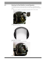
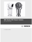
1
MIC Series 500 Camera MIC Series 500 en User’s Manual MIC Series 500 Camera Table of Contents | en 3 Table of Contents 1 Safety 5 1.1 Important Safety Instructions 5 1.2 Safety Precautions 6 1.3 Important Notices 1.4 Customer Support and Service 11 2 Unpacking 12 2.1 Parts List 12 2.2 Additional Tools Required 12 3 Description 13 3.1 Features 13 3.2 Power 13 3.3 Video 13 7 4 Mounting 14 4.1 Adjusting the MIC 500 Series Camera 15 4.2 Adjusting the Rain Shield for Inverted Operation 17 4.3 Mounting the MIC 500 Series Camera 18 4.4 Earthing the MIC 500 Series Camera 19 4.5 Lightning Protection 19 4.6 Electrical Connections 19 5 Navigating the Menus 22 5.1 MIC Setups Menu 24 5.1.1 Config Mode 26 5.2 Activate Feature Menu 26 5.3 Preset Tour Menu 26 5.3.1 Create/Modify Tour 27 5.3.2 Random Tours 27 5.4 Pattern Tour Menu 28 5.5 Presets Menu 29 5.5.1 Learn Preset 29 5.5.2 GOTO Preset 29 5.5.3 Manual Control 30 5.6 Communications Menu 30 5.7 Advanced Setups Menu 31 5.7.1 Factory Defaults 33 5.7.2 Re-map Pelco Aux (Pelco D and P Protocols only) 33 5.8 Alarms Menu 34 5.8.1 Alarm Relays and Re-arm Time 35 5.9 Sony Set Menu 35 5.9.1 Mapping to a MIC 500 Series Camera Function 36 5.10 Captions Menu 42 5.10.1 Default Caption 43 Bosch Security Systems, Inc. User’s Manual F.01U.173.601 | 2.0 | 2010.11 4 en | Table of Contents MIC Series 500 Camera 5.10.2 Preset Captions 43 5.10.3 Sector Captions 43 5.10.4 Setting Captions 43 5.11 Privacy Menu 45 5.11.1 Mask / Clear Whole 45 5.11.2 Setting the Privacy Zones 45 5.12 Pot Test Menu 46 5.13 MIC Information Menu 46 5.13.1 MIC Information Menus 48 5.14 Set User Access Menu 48 5.14.1 Factory Defaults 49 5.15 Help Menu 50 5.16 Self Diagnosis 50 A Appendices 51 A.1 MIC 500 Series Aux Controls 51 A.2 MIC 500 Preset Controls 52 A.3 MIC 500 Model Numbers and Descriptions 54 F.01U.173.601 | 2.0 | 2010.11 User’s Manual Bosch Security Systems, Inc. MIC Series 500 Camera Safety | en 1 Safety 1.1 Important Safety Instructions 5 Read, follow, and retain for future reference all of the following safety instructions. Heed all warnings on the unit and in the operating instructions before operating the unit. 1. Cleaning - Unplug the unit from the outlet before cleaning. Follow any instructions provided with the unit. Generally, using a dry cloth for cleaning is sufficient, but a moist fluff-free cloth or leather shammy may also be used. Do not use liquid cleaners or aerosol cleaners. 2. Heat Sources - Do not install the unit near any heat sources such as radiators, heaters, stoves, or other equipment (including amplifiers) that produce heat. 3. Ventilation - The MIC 500 Series camera is a completely sealed unit and requires no special consideration as regards to ventilation. 4. Water - Do not install the camera power supply near water for example near a bathtub, washbowl or swimming pool. The power supplies carry an IP65 rating and are suitable for outside installation but for security reasons Bosch recommend that they are installed in a suitable equipment cabinet. The camera unit is sealed to IP68 and can be safely used in damp environments or outdoors, as long as the base cable connector is suitably sealed. 5. Object and liquid entry - With the exception of the base connector, the MIC 500 Series Camera can be exposed to non corrosive liquids without damage. Never push objects into the base connector as this may damage the connection pins and prevent the camera operating correctly. 6. Lightning - For added protection during a lightning storm, or when leaving this unit unattended and unused for long periods, unplug the unit from the wall outlet and disconnect the cable system. This will prevent damage to the unit from lightning and power line surges. 7. Controls adjustment - Adjust only those controls specified in the operating instructions. Improper adjustment of other controls may cause damage to the unit. 8. Overloading - Do not overload outlets and extension cords. This can cause fire or electrical shock. 9. Power cord and plug protection - Protect the plug and power cord from foot traffic, being pinched by items placed upon or against them at electrical outlets, and its exit from the unit. For units intended to operate with 230 VAC, 50 Hz, the input and output power cord must comply with the latest versions of IEC Publication 227 or IEC Publication 245. 10. Power disconnect - Units with or without ON/OFF switches have power supplied to the unit whenever the power cord is inserted into the power source; however, the unit is operational only when the ON/OFF switch is in the ON position. The power cord is the main power disconnect device for switching off the voltage for all units. 11. Power sources - Operate the unit only from the type of power source indicated on the label. Before proceeding, be sure to disconnect the power from the cable to be installed into the unit. – For battery powered units, refer to the operating instructions. – For external power supplied units, use only the recommended or approved power supplies. – For limited power source units, this power source must comply with EN60950. Substitutions may damage the unit or cause fire or shock. – For 24 VAC units, voltage applied to the unit's power input should not exceed ±10%, or 28 VAC. User-supplied wiring must comply with local electrical codes (Class 2 Bosch Security Systems, Inc. User’s Manual F.01U.173.601 | 2.0 | 2010.11 6 en | Safety MIC Series 500 Camera power levels). Do not ground the supply at the terminals or at the unit's power supply terminals. – If unsure of the type of power supply to use, contact your dealer or local power company. 12. Servicing - Do not attempt to service this unit yourself. Opening or removing covers may expose you to dangerous voltage or other hazards. Refer all servicing to qualified service personnel. 13. Damage requiring service - Unplug the unit from the main AC power source and refer servicing to qualified service personnel when any damage to the equipment has occurred, such as: – the power supply cord or plug is damaged; – liquid has been spilled in the equipment; – an object has fallen into the unit; – the unit has been dropped or the unit cabinet is damaged; – the unit exhibits a distinct change in performance; – the unit does not operate normally when the user correctly follows the operating instructions. 14. Replacement parts - Be sure the service technician uses replacement parts specified by the manufacturer, or that have the same characteristics as the original parts. Unauthorized substitutions may cause fire, electrical shock, or other hazards. 15. Safety check - Safety checks should be performed upon completion of service or repairs to the unit to ensure proper operating condition. 16. Installation - Install in accordance with the manufacturer's instructions and in accordance with applicable local codes. 17. Attachments, changes or modifications - Only use attachments/accessories specified by the manufacturer. Any change or modification of the equipment, not expressly approved by Bosch, could void the warranty or, in the case of an authorization agreement, authority to operate the equipment. 1.2 Safety Precautions DANGER! This symbol indicates an imminently hazardous situation such as “Dangerous Voltage” inside the product. If not avoided, this will result in an electrical shock, serious bodily injury, or death. WARNING! Indicates a potentially hazardous situation. If not avoided, this could result in serious bodily injury or death. CAUTION! Indicates a potentially hazardous situation. If not avoided, this may result in minor or moderate injury. Alerts the user to important instructions accompanying the unit. CAUTION! Indicates a potentially hazardous situation. If not avoided, this may result in property damage or risk of damage to the unit. F.01U.173.601 | 2.0 | 2010.11 User’s Manual Bosch Security Systems, Inc. MIC Series 500 Camera Safety | en 7 NOTICE! This symbol indicates information or a company policy that relates directly or indirectly to the safety of personnel or protection of property. 1.3 Important Notices Accessories - Do not place this unit on an unstable stand, tripod, bracket, or mount. The unit may fall, causing serious injury and/or serious damage to the unit. Use only with the cart, stand, tripod, bracket, or table specified by the manufacturer. When a cart is used, use caution and care when moving the cart/apparatus combination to avoid injury from tip-over. Quick stops, excessive force, or uneven surfaces may cause the cart/unit combination to overturn. Mount the unit per the manufacturer's instructions. All-pole power switch - Incorporate an all-pole power switch, with a contact separation of at least 3 mm in each pole, into the electrical installation of the building.If it is needed to open the housing for servicing and/or other activities, use this all-pole switch as the main disconnect device for switching off the voltage to the unit. Camera grounding - For mounting the camera in potentially damp environments, ensure to ground the system using the ground connection of the power supply connector (see section: Connecting external power supply). Camera lens - An assembled camera lens in the outdoor housing must comply and be tested in accordance with UL/IEC60950. Any output or signal lines from the camera must be SELV or Limited Power Source. For safety reasons the environmental specification of the camera lens assembly must be within the environmental specification of -10 °C (14 °F) to 50 °C (122 °F). Camera signal - Protect the cable with a primary protector if the camera signal is beyond 140 feet, in accordance with NEC800 (CEC Section 60). Coax grounding: – Ground the cable system if connecting an outside cable system to the unit. – Connect outdoor equipment to the unit's inputs only after this unit has had its grounding plug connected to a grounded outlet or its ground terminal is properly connected to a ground source. – Disconnect the unit's input connectors from outdoor equipment before disconnecting the grounding plug or grounding terminal. – Follow proper safety precautions such as grounding for any outdoor device connected to this unit. U.S.A. models only - Section 810 of the National Electrical Code, ANSI/NFPA No.70, provides information regarding proper grounding of the mount and supporting structure, grounding of the coax to a discharge unit, size of grounding conductors, location of discharge unit, connection to grounding electrodes, and requirements for the grounding electrode. NOTICE! This device is intended for use in public areas only. U.S. federal law strictly prohibits surreptitious recording of oral communications. Your Bosch product was developed and manufactured with high-quality material and components that can be recycled and reused. This symbol means that electronic and electrical appliances, which have reached the end of their working life, must be collected and disposed of separately from household waste material. Separate collecting systems are usually in place for disused electronic and electrical products. Please dispose of these units at an environmentally compatible recycling facility, per European Directive 2002/96/EC. Bosch Security Systems, Inc. User’s Manual F.01U.173.601 | 2.0 | 2010.11 8 en | Safety MIC Series 500 Camera Environmental statement - Bosch has a strong commitment towards the environment. This unit has been designed to respect the environment as much as possible. Electrostatic-sensitive device - Use proper CMOS/MOS-FET handling precautions to avoid electrostatic discharge. NOTE: Wear required grounded wrist straps and observe proper ESD safety precautions when handling the electrostatic-sensitive printed circuit boards. Fuse rating - For security protection of the device, the branch circuit protection must be secured with a maximum fuse rating of 16A. This must be in accordance with NEC800 (CEC Section 60). Grounding and polarization - This unit may be equipped with a polarized alternating current line plug (a plug with one blade wider than the other blade). This safety feature allows the plug to fit into the power outlet in only one way. If unable to insert the plug fully into the outlet, contact a locally certified electrician to replace the obsolete outlet. Do not defeat the safety purpose of the polarized plug. Alternately, this unit may be equipped with a 3-pole grounding plug (a plug with a third pin for earth grounding). This safety feature allows the plug to fit into a grounded power outlet only. If unable to insert the plug into the outlet, contact a locally certified electrician to replace the obsolete outlet. Do not defeat the safety purpose of the grounding plug. Moving - Disconnect the power before moving the unit. Move the unit with care. Excessive force or shock may damage the unit. Outdoor signals - The installation for outdoor signals, especially regarding clearance from power and lightning conductors and transient protection, must be in accordance with NEC725 and NEC800 (CEC Rule 16-224 and CEC Section 60). Permanently connected equipment - Incorporate a readily accessible disconnect device in the building installation wiring. Pluggable equipment - Install the socket outlet near the equipment so it is easily accessible. Power disconnect - Units have power supplied whenever the power cord is inserted into the power source. The power cord is the main power disconnect for all units. Power lines - Do not locate the camera near overhead power lines, power circuits, or electrical lights, nor where it may contact such power lines, circuits, or lights. Video loss - Video loss is inherent to digital video recording; therefore, Bosch Security Systems cannot be held liable for any damage that results from missing video information. To minimize the risk of lost digital information, Bosch Security Systems recommends multiple, redundant recording systems, and a procedure to back up all analog and digital information. NOTICE! This is a class B product. In a domestic environment this product may cause radio interference, in which case the user may be required to take adequate measures. FCC & ICES Information (U.S.A. and Canadian Models Only) This equipment has been tested and found to comply with the limits for a Class B digital device, pursuant to part 15 of the FCC Rules. These limits are designed to provide reasonable protection against harmful interference in a residential installation. This equipment generates, uses, and can radiate radio frequency energy and, if not installed and used in accordance with the instructions, may cause harmful interference to radio communications. However, there is no guarantee that interference will not occur in a particular installation. If this equipment does cause harmful interference to radio or television reception, which can be F.01U.173.601 | 2.0 | 2010.11 User’s Manual Bosch Security Systems, Inc. MIC Series 500 Camera Safety | en 9 determined by turning the equipment off and on, the user is encouraged to try to correct the interference by one or more of the following measures: – reorient or relocate the receiving antenna; – increase the separation between the equipment and receiver; – connect the equipment into an outlet on a circuit different from that to which the – consult the dealer or an experienced radio/TV technician for help. receiver is connected; Intentional or unintentional modifications, not expressly approved by the party responsible for compliance, shall not be made. Any such modifications could void the user's authority to operate the equipment. If necessary, the user should consult the dealer or an experienced radio/television technician for corrective action. The user may find the following booklet, prepared by the Federal Communications Commission, helpful: How to Identify and Resolve Radio-TV Interference Problems. This booklet is available from the U.S. Government Printing Office, Washington, DC 20402, Stock No. 004000-00345-4. INFORMATIONS FCC ET ICES (modèles utilisés aux États-Unis et au Canada uniquement) Suite à différents tests, cet appareil s'est révélé conforme aux exigences imposées aux appareils numériques de classe B, en vertu de la section 15 du règlement de la Commission fédérale des communications des États-Unis (FCC), et en vertu de la norme ICES-003 d'Industrie Canada. Ces exigences visent à fournir une protection raisonnable contre les interférences nuisibles lorsque l'appareil est utilisé dans le cadre d'une installation résidentielle. Cet appareil génère, utilise et émet de l'énergie de radiofréquences et peut, en cas d'installation ou d'utilisation non conforme aux instructions, engendrer des interférences nuisibles au niveau des radiocommunications. Toutefois, rien ne garantit l'absence d'interférences dans une installation particulière. Il est possible de déterminer la production d'interférences en mettant l'appareil successivement hors et sous tension, tout en contrôlant la réception radio ou télévision. L'utilisateur peut parvenir à éliminer les interférences éventuelles en prenant une ou plusieurs des mesures suivantes: – Modifier l'orientation ou l'emplacement de l'antenne réceptrice; – Éloigner l'appareil du récepteur; – Brancher l'appareil sur une prise située sur un circuit différent de celui du récepteur; – Consulter le revendeur ou un technicien qualifié en radio/télévision pour obtenir de l'aide. Toute modification apportée au produit, non expressément approuvée par la partie responsable de l'appareil, est strictement interdite. Une telle modification est susceptible d'entraîner la révocation du droit d'utilisation de l'appareil. La brochure suivante, publiée par la Commission fédérale des communications (FCC), peut s'avérer utile : How to Identify and Resolve Radio-TV Interference Problems (Comment identifier et résoudre les problèmes d’interférences de radio et de télévision). Cette brochure est disponible auprès du U.S. Government Printing Office, Washington, DC 20402, États-Unis, sous la référence n° 004-000-00345-4. Disclaimer Underwriter Laboratories Inc. (“UL”) has not tested the performance or reliability of the security or signaling aspects of this product. UL has only tested fire, shock and/or casualty hazards as outlined in UL's Standard(s) for Safety for Closed Circuit Television Equipment, UL 2044. UL Certification does not cover the performance or reliability of the security or signaling aspects of this product. Bosch Security Systems, Inc. User’s Manual F.01U.173.601 | 2.0 | 2010.11 10 en | Safety MIC Series 500 Camera UL MAKES NO REPRESENTATIONS, WARRANTIES, OR CERTIFICATIONS WHATSOEVER REGARDING THE PERFORMANCE OR RELIABILITY OF ANY SECURITY OR SIGNALING RELATED FUNCTIONS OF THIS PRODUCT. Disclaimer Underwriter Laboratories Inc. (“UL”) has not tested the performance or reliability of the security or signaling aspects of this product. UL has only tested fire, shock and/or casualty hazards as outlined in UL's Standard(s) for Safety for Information Technology Equipment, UL 60950-1. UL Certification does not cover the performance or reliability of the security or signaling aspects of this product. UL MAKES NO REPRESENTATIONS, WARRANTIES, OR CERTIFICATIONS WHATSOEVER REGARDING THE PERFORMANCE OR RELIABILITY OF ANY SECURITY OR SIGNALINGRELATED FUNCTIONS OF THIS PRODUCT. Copyright This user guide is the intellectual property of Bosch Security Systems, Inc. and is protected by copyright. All rights reserved. Trademarks All hardware and software product names used in this document are likely to be registered trademarks and must be treated accordingly. NOTICE! This user guide has been compiled with great care and the information it contains has been thoroughly verified. The text was complete and correct at the time of printing. The ongoing development of the products may mean that the content of the user guide can change without notice. Bosch Security Systems accepts no liability for damage resulting directly or indirectly from faults, incompleteness or discrepancies between the user guide and the product described. F.01U.173.601 | 2.0 | 2010.11 User’s Manual Bosch Security Systems, Inc. MIC Series 500 Camera 1.4 Safety | en 11 Customer Support and Service If this unit needs service, contact the nearest Bosch Security Systems Service Center for authorization to return and shipping instructions. Service Centers USA Repair Center Telephone: 800-566-2283 Fax: 800-366-1329 E-mail: [email protected] Customer Service Telephone: 888-289-0096 Fax: 585-223-9180 E-mail: [email protected] Technical Support Telephone: 800-326-1450 Fax: 585-223-3508 or 717-735-6560 E-mail: [email protected] Canada Telephone: 514-738-2434 Fax: 514-738-8480 Europe, Middle East, Africa Region Repair Center Telephone: 31 (0) 76-5721500 Fax: 31 (0) 76-5721413 E-mail: [email protected] Asia Region Repair Center Telephone: 65 63522776 Fax: 65 63521776 E-mail: [email protected] Customer Service Telephone: 86 (0) 756 7633117 or 86 (0) 756 7633121 Fax: 86 (0) 756 7631710 E-mail: [email protected] Warranty and additional information For additional information and warranty queries, please contact your Bosch Security Systems representative or visit our website at www.boschsecurity.com. Bosch Security Systems, Inc. User’s Manual F.01U.173.601 | 2.0 | 2010.11 12 2 en | Unpacking MIC Series 500 Camera Unpacking This equipment should be unpacked and handled with care. If an item appears to have been damaged in shipment, notify the shipper immediately. Verify that all the parts listed in the Parts List below are included. If any items are missing, notify your Bosch Security Systems Sales or Customer Service Representative. The original packing carton is the safest container in which to transport the unit and must be used if returning the unit for service. Save it for possible future use. NOTICE! Do not stand the canted (45°) MIC 500 Series Camera upright as it is unstable unless properly mounted. 2.1 Parts List The package containing the MIC 500 Series Camera should include the following items: Quantity Part 1 MIC 500 Series Camera 1 Installation and Configuration CD (including user manuals and protocol packs) 1 Quick Installation Guide 1 MIC-USB485CVTR signal converter (enabling connection of MIC 500 Series Camera to a PC) 2.2 Additional Tools Required The following table lists additional tools required (not supplied by Bosch): Quantity Part 1 13 mm spanner for MIC 500 Series Camera PCD foot, fixing bolts 1 3 mm screwdriver for the terminal blocks in power supply 1 8 mm screwdriver for MIC Series PSU enclosure fixing screws 1 No. 2 Phillips screwdriver for MIC 500 Series Camera rain shield adjustment, if required 1 F.01U.173.601 | 2.0 | 2010.11 Nebar gasket or suitable silicone sealant for ensuring a water tight seal User’s Manual Bosch Security Systems, Inc. MIC Series 500 Camera 3 Description | en 13 Description The MIC 500 Series Camera is a fully functional, quality built, pan/tilt/zoom CCTV camera which has been designed to provide a robust, high quality, feature rich CCTV solution suitable for most security applications. The camera features an IP68 weatherproof, robust, cast aluminium housing for lightweight strength and durability utilizing brushless motors for precise control and quiet operation. Comprehensive onboard software allows an installer to configure a new MIC 500 Series camera for use quickly, or for a CCTV operator to set up presets, tours, alarms (if fitted), privacy masks (if fitted) easily, and to control nearly all other camera functions directly from the CCTV control room, no matter which control system is in use. In addition, the camera can also be configured from a PC using the MIC Series Universal Camera Setup Software (cam-set) and the MIC-USB485CVTR converter, both provided with the camera.Bosch Security Systems’ MIC Series Universal Camera Setup Software is also referred to as 'cam-set' within the product literature hereafter. Please see the MICUSB485CVTR and the MIC Series Universal Camera Setup Software Installation Manual or the Cam-set help file for details on connecting the MIC-USB485CVTR to the MIC 500 Series camera. 3.1 Features The MIC 500 Series Camera has been designed with the following features: – Brushless motor technology for quiet whisper operation – Multi-protocol operation – On-screen menu for configuration and operation – Privacy function (if fitted; see model numbers in Appendix) – New “twist-lock” canting for easy field adjustment – Industry-leading programmable camera module function – Wide range of mounting options for varied applications in even the harshest environments 3.2 – Optically flat viewing window – Reversible rain shield – IP68 rating Power The recommended power cable is a 2-conductor, 14-18 gauge cable, depending on the distance (cables MIC-2MS, MIC-10MS, MIC-20MS, MIC-25MS). 3.3 Video The video coax cable should use a shield coverage copper braid 95% and standard copper center conductor. Recommended cables are RG-59, RG-6/U, or RG-11U. Cable Type Maximum Distance RG-59/U 300 m (1000 ft) RG-6/U 450 m (1500 ft) RG-11/U 600 m (2000 ft) Size O.D. between 4.6 mm (0.181 in.) and 7.9 mm (0.312 in.) Shield Copper braid: 95% Central Conductor Standard copper center Terminal Connector BNC Bosch Security Systems, Inc. User’s Manual F.01U.173.601 | 2.0 | 2010.11 14 4 en | Mounting MIC Series 500 Camera Mounting Installation should be made by qualified service personnel and conform to the National Electrical Code and applicable local codes. The MIC 500 Series Camera range has been designed for easy installation on a variety of common fittings. The most common type of mount used is a dedicated CCTV camera pole where the camera is bolted directly to the top of the pole using industry standard 4 in. (101.6 mm) fittings. This type of camera pole provides a robust mounting platform that minimizes camera motion and typically has a large base cabinet for mounting ancillary equipment such as power supplies. The camera can also be mounted on lamp post columns using the Pole Mount Bracket (MICPMB); however, users should be aware that lamp posts can often be subject to movement and are not suitable platforms in all conditions or for all applications. The following mounting brackets are available: Part Description MIC-SPA Wall Spreader Plate MIC-PMB Pole Mount Bracket MIC-CMB Corner Mount Bracket MIC-WMB Wall Mount Bracket MIC-SCA Shallow Conduit Adaptor MIC-DCA Deep Conduit Adaptor For mounting directly to a building, brackets are available for all typical building installations such as upright (90°), canted (45°), or inverted. Figure 4.1 Typical pole mount arrangement (MIC-PMB with MIC-SCA and MIC-WMB) Figure 4.2 Typical wall mounting arrangement (MIC-SPA, MIC-SCA and MIC-WMB) F.01U.173.601 | 2.0 | 2010.11 User’s Manual Bosch Security Systems, Inc. MIC Series 500 Camera Mounting | en Figure 4.3 4.1 15 Typical wall corner mounting arrangement (MIC-CMB, MIC-SCA and MIC-WMB) Adjusting the MIC 500 Series Camera The MIC 500 Series Camera is suitable for adjustment from the upright position (90°) to a canted (45°) position. Figure 4.4 Pan body fixing screws To adjust the MIC 500 Series Camera, follow these steps: 1. 2. Firmly secure the camera base by the 4 inch PCD foot bolts. Locate and remove the two (2) pan body fixing screws. Once the screws have been loosened, lift them up and continue turning to lock the screws open. Ensure not to damage the paint work on the camera. Figure 4.5 Security screws NOTICE! The small security screws are not designed to be removed. Any attempt to remove these screws will void the warranty and potentially cause serious damage to the camera. Bosch Security Systems, Inc. User’s Manual F.01U.173.601 | 2.0 | 2010.11 16 en | Mounting MIC Series 500 Camera 3. Grasp the lower camera body beneath the pan body joint and then carefully twist the upper camera body clockwise until the camera body has rotated 180° around, canting the top part of the camera to the 45° angle. Ensure that the securing bolt holes are aligned. Figure 4.6 4. Canting in progress Carefully replace and tighten the pan body securing the supplied (MIC-DCA, MIC-SCA, MIC-WMB) bolts. Ensure not to damage the paint work on the camera. Figure 4.7 5. Camera canted The MIC 500 Series Camera is now ready to be installed and configured. NOTICE! Installation should be made by qualified service personnel and conform to the National Electrical Code and applicable local codes. Ensure a strong safety chain is used to secure the MIC 500 Series Camera to prevent any danger of dropping the product during installation. The following graphic shows the various positions of the MIC 500 Series Camera. See the table below for the descriptions. Figure 4.8 MIC 500 Series Cameras (From left to right: Canted full frontal view; Upright full frontal view; Upright side view; Canted side view) F.01U.173.601 | 2.0 | 2010.11 User’s Manual Bosch Security Systems, Inc. MIC Series 500 Camera 4.2 Mounting | en 17 Adjusting the Rain Shield for Inverted Operation The upright unit can be mounted either with the camera ball up or down.When inverted, reverse the rain shield to provide weather protection for the window glass by following these steps: 1. Remove the 4 of M3 x 6 screws fixing the rain shield to the face of the camera. Figure 4.9 2. Figure 4.10 3. Reverse rain shield Reattach the rain shield to the camera face. Figure 4.11 Bosch Security Systems, Inc. Remove screws Reverse the rain shield. Inverted rain shield User’s Manual F.01U.173.601 | 2.0 | 2010.11 18 en | Mounting MIC Series 500 Camera 4. Install the camera. 5. Using the On Screen Menu (MIC Setups, Config options), set the camera to 'Inverted.' This automatically sets the controls and video for inverted operation. Note: The camera can also be set to an inverted configuration through cam-set. For further details on configuring and reversing the controls using cam-set, please see the cam-set Instruction and Help file. 4.3 Mounting the MIC 500 Series Camera To mount the MIC 500 Series Camera, follow these steps: 1. 2. Identify a secure location for the mount (supplied separately). Ensure that the mounting surface is capable of supporting the combined weight of the camera and mounting hardware under all expected conditions of load, vibration, and temperature. 3. Carefully lift the camera to the mounting point and connect the female cable 12 pin connector to the male plug in the base of the camera. Screw the cable connector sleeve onto the plug until it is firmly secured (approximately four (4) turns from the start of thread engagement). 4. Earth the camera using one of the securing supplied bolts. Only earth the camera at a single point to prevent earth loops and hum bars. 5. User M8 x20 mm Stainless steel nuts, bolts, and washers to secure the cameras 4 in. PCD base to the mounting bracket. An additional Nebar gasket or suitable silicone sealant can be used to ensure a water tight seal between the 4 in. PCD base and mounting surface. Tighten all bolts securely. Secure all cabling and conduit. WARNING! If the camera is mounted ball down, it is essential that the connector and base area of the camera are completely sealed from water ingress. Any water getting into the connector is liable to cause corrosion to the connector pins, leading to unreliable operation of the camera unit. WARNING! To prevent water from penetrating the composite cable connector threads, the 25 mm thread should be sealed at final installation using PTFE tape (not supplied). Alternatively, a suitable sealant may be liberally applied to the thread prior to final tightening. F.01U.173.601 | 2.0 | 2010.11 User’s Manual Bosch Security Systems, Inc. MIC Series 500 Camera Mounting | en Figure 4.12 4.4 19 MIC 500 Series camera mounting positions: Inverted, Upright, and Canted Earthing the MIC 500 Series Camera The camera module and housing are electrically isolated; however, it is recommended that the housing be earthed for safety. This safety earth should be a bonding connection, such as one of the securing bolts, to the outside case of the camera. The camera should be earthed to prevent ground loops and video distortion caused by electrical interference. If the system is copper throughout and the camera pictures are fed back to the control room coaxial copper cable, the camera should be earthed at the video termination point in the control room. If the video is transmitted back to the control room via some non electrical connecting medium (for example, fiber optic, radio, or microwave link), the camera should be earthed at the transmitter point in the Power Supply Unit. If dual earthing is unavoidable, a video isolation transformer should be fitted between the two (2) earths. 4.5 Lightning Protection If the camera is positioned in a highly exposed area where lightning strikes may occur, it is recommended to install a lightning conductor within 0.5 m of the camera and at least 1.5 m higher than the camera. The construction of the housing itself is capable of coping with secondary strikes. If the correct lightning protection is applied, no damage to the internal electronics or camera should result. Additionally, an earth bonding connection to the case provides protection against damage from secondary strikes. 4.6 Electrical Connections All connections to the camera are provided through the screw terminal connections in the MIC power supply. A purpose-built composite cable for use with the camera is available in lengths of 2 m, 10 m, 20 m, and 25 m (required, not supplied); these cables are pre-made with a female terminated 12 way connector fitted to them for attachment to the male connector installed into the base of the camera. Bosch Security Systems, Inc. User’s Manual F.01U.173.601 | 2.0 | 2010.11 20 en | Mounting MIC Series 500 Camera Figure 4.13 Composite cable before connection Figure 4.14 View of the Composite Cable connected to a MIC 500 Series camera Refer to the MIC Series Power Supply Installation Manual included on the Installation CD for full details on installing a MIC Series Power Supply Unit and connecting to a MIC 500 Series Camera.The composite cable has no termination (free wires) at the other end for wiring into the power supply. The standard color coding used in these cables is as follows: Figure 4.15 Exploded View of Composite Cable Connections Camera Cable Signal Name Description Cable Wire Color 1 Washer Drive Rtn Auxiliary Connection Grey 2 Tamper Sw Rtn Auxiliary Connection Brown 3 Washer Drive Wash Signal Orange 4 Tamper Sw Alarm Communications Black Connector Pin F.01U.173.601 | 2.0 | 2010.11 User’s Manual Bosch Security Systems, Inc. MIC Series 500 Camera Mounting | en Camera Cable 21 Signal Name Description Cable Wire Color 5 Video Return Video Signal Ground Coax Screen 6 Video Output Video Output to Control Room Coax Core 7 Full Duplex Tx B Telemetry I/O to RS-422/485 Violet 8 Full Duplex Tx A Telemetry I/O to RS-422/485 Blue 9 0v Ground Shield Full Duplex Rx A Telemetry I/O to RS-422/485 Yellow Telemetry I/O to RS-422/485 White Connector Pin 10 Half Duplex Tx/Rx A 11 Full Duplex Rx B Half Duplex Tx/Rx B 12 Power Input 2 Low Voltage Power Input Green 13 Power Input 1 Low Voltage Power Input Red NOTICE! Use of the shielded composite cable for distances in excess of 25 m between the camera and the MIC power supply is not recommended. WARNING! Ensure that all power is disconnected before opening or working on the MIC power supply. Installation should be made by qualified service personnel and conform to the National Electrical Code and applicable local codes. Ensure a strong safety chain is used to secure the MIC 500 Series Camera to prevent any danger of dropping the product during installation. Bosch Security Systems, Inc. User’s Manual F.01U.173.601 | 2.0 | 2010.11 22 5 en | Navigating the Menus MIC Series 500 Camera Navigating the Menus The MIC 500 Series Camera is programmed through the on-screen display (OSD) menus. Each displays a list of parameters or submenus that you can select. To access the main menu, use one of two (2) methods: – PC-based control system where you must identify preset command 85. – Manual control via a compatible joystick If the control system does not support presets or is limited to a preset number less than 85, tilt the unit upward until it hits the mechanical stop point, and then hold the joystick for approximately 10 seconds. The menu appears. To access the main menu via manual control: 1. Press Shot + 85 + Enter (Bosch controller). The main menu appears. 2. If this is the first time that you are using the camera, or if it is locked, you must enter the password to access all menu options. 3. Move the joystick down to ENTER PASSWORD, then move it to the right to enter the submenu. PASSWORD “0000” appears. 4. Move the joystick to the right. The “0000” turns green and the first number starts to blink. 5. Move the joystick up to change the first “0” to a “1”. The password should now be “1000,” which is the only valid password and can never be changed. 6. Move the joystick to the left to exit the menu. PASSWORD VALID appears. – Tips to remember when navigating throughout the menus via the control: – If the menu receives no manual controls for three (3) minutes, it automatically closes, returning the camera to its previous state. Any settings not saved are lost. – Menu items appear in white, with the current item highlighted in either blue or green. If a line is highlighted in blue, use the up and down commands to move through the menu. If the line is highlighted in green, use the up and down commands to scroll through the settings for that option. For numbers, move the joystick up to increase the numbers, and down to decrease the numbers. Move the joystick left and right to move between numbers. – A right command can do one of two things: Move into the current option displaying all the options available, or select the current option by changing from blue to green, allowing the user to select a new value for this setting. – A left command goes back a menu level or sets the setting that you just modified. – Up and down commands scroll through the list and right to move into the next level of the menu. Pressing right on EXIT turns off the menu. – For some menu items there are slight differences. For example, the Set-up Tour and Sony Set options from the main page request a number before moving into the settings. This sequence is: Select SETUP TOUR, then send right. Use the up and down to move between tour numbers, and then right again to enter the tour sub menus. The contents of the first screen is dependent on the level of user access defined by the installer under the password locked section of the menu. MAIN MENU MIC SETUPS ACTIVATE FEATURE PRESET TOUR PATTERN TOUR PRESETS COMMUNICATIONS ADVANCED SETUPS ALARMS F.01U.173.601 | 2.0 | 2010.11 1/2 MAIN MENU SONY SET CAPTIONS PRIVACY POT TEST MIC INFORMATION SET USER ACCESS HELP EXIT User’s Manual 2/2 Bosch Security Systems, Inc. MIC Series 500 Camera Navigating the Menus | en Menu Item Description MIC SETUPS Controls adjustable camera settings such as: homing, wiping, OSD, positioning, alarm, 23 zooming, and self diagnostic testing. ACTIVATE FEATURE Initiates a Preset or Pattern tour once the menu is closed, or to directly call up an individual SonySet preset. PRESET TOUR Recalls preset positions in the set order waiting at each preset for the desired dwell time. Up to four (4) separate preset tours may be programmed concurrently. PATTERN TOUR Mimics the user's movements while recording so it can follow a specific path. Up to two (2) separate pattern tours may be programmed concurrently. PRESETS Preselects and stores combinations of pan, tilt, and zoom positions, which allow a set view to be recalled. Also known as preset shot. COMMUNICATIONS Provides the selection of the MIC Address, Protocol and Baud Rate. Once modified, the settings only take effect once the menu has been exited and the confirmation page has been accepted. The address field allows values in the range 1 to 254, which will be carried over between protocols. ADVANCED SETUPS Accesses the advanced features menu. ALARMS Accesses the alarm settings such as: input type, time-out options, and dwell time. SONY SET Enables the user to select the SonySet Preset number. CAPTIONS Allows the setting of the default caption and the preset or sector captions as well as the associated options. The main page contains settings that relate to all three (3) caption modes such as position and color. It also determines if captions are used and if so which ones. The vertical position selects a line from 0 to 10 (0 being the top of the screen and 10 the bottom). Note: setting captions will disable the camera on screen display icons (digital zoom, etc). PRIVACY Contains common privacy controls. Further setups can be found through the Cam-set. POT TEST Indicates the MIC 500 Series Camera's current position, motor readings, and camera supply voltage from the power supply. MIC INFORMATION Offers the user a quick way of viewing the current MIC 500 Series Camera settings and measurements. Included in these pages is a comprehensive list of MIC data (address, serial number, baud rate etc), a list of control card data, a read only list of MIC settings (MIC SETUPS and ADVANCED SETUPS), a preset mapping list (for auxiliaries and Sony Set), temperature and humidity measurements, statistical timers, and communication error logs. SET USER ACCESS Contains the name of each of the Main Menu options where a simple Yes or No option indicates if shown under normal use. When the menu is exited and re-opened, the password access is reset and only the items selected are visible to the user. At the top of the first user access page are 2 options, “Set Full Access” and “Set No Access.” These allow and disable all features respectively by selecting with a right command. HELP Contains contact information. EXIT Exits the menu. Bosch Security Systems, Inc. User’s Manual F.01U.173.601 | 2.0 | 2010.11 24 en | Navigating the Menus 5.1 MIC Series 500 Camera MIC Setups Menu This section contains some of the more commonly modified settings for the MIC 500 Series Camera. Pressing right on an option changes the highlight color to green and allows the modification of the current setting value. MAIN MENU MIC SETUPS ACTIVATE FEATURE PRESET TOUR PATTERN TOUR PRESETS COMMUNICATIONS ADVANCED SETUPS ALARMS 1/2 MIC SETUPS CONFIG 1/2 UPRIGHT AUTO HOME HOME TO WASH-WIPE OSD POS DISPLAY AUTO ALARM ON PRESET OFF OFF OFF OFF Menu Item Description CONFIG Available only via the menu see Section 5.1.1 Config Mode, page 26. MIC SETUPS DIGITAL ZOOM AUTO FLIP SELF DIAGNOSIS 2/2 ON OFF AUTO HOME Enables the unit to remain stationary when set to OFF or until the next user input. With Auto HOME TO Home turned on, the MIC 500 Series Camera can be can be configured to either move to the home position (preset 1), start preset tour 1, or play pattern tour 1 using the “Home To” setting. The amount of time before this takes place can be set to 30 seconds, 1 minute, 5 minutes, or 1 hour using the “Home Time” Setting in “Advanced Controls.” WASH-WIPE Upon activation, the camera moves to a saved position (Wash Wipe Position, Advanced settings), which should be set to look at the washer nozzle, starts the washer pump, and turns the wiper on. Once released, the unit returns to its original position, stops the washer pump, and continues wiping for a few seconds. This process only takes place if the Wash Wipe command is turned on; otherwise, the camera just activates the washer pump and will not move. If use of an external washer is required, then either the MIC-WKT (washer nozzle and bracket and MIC-WSH card) or MIC-WKT-IR (washer nozzle and bracket) kits should be purchased to enable a third party washer pump to be installed (see separate MIC-WKT manual). OSD (on-screen Displays the camera module information icons on the video, such as zoom position, white display) balance mode, shutter speed etc. This is only displayed when there are no captions on the screen. POS DISPLAY Indicates the current heading in degrees of the MIC 500 Series Camera in pan and tilt relative to its zero position, this is set during installation. The MIC 500 Series Camera takes 0° as North, so when the MIC 500 Series Camera is installed ensure the unit is pointed towards North, on a level tilt, then use “Set Zero Pos” in “Advanced Controls.” When activated, the position display shows the current compass heading North, South, East or West in a 1 or 2 character code N, NW, W, SW, S etc, along with an accurate pan and tilt bearing. The display is shown in white and resembles “N PAN: 125 TILT: 10." AUTO ALARM Enables use for both single or multi alarm functionality. With Auto Alarm on, the MIC moves to the Auto Alarm position (as configured using Cam-set, or “Alarms” - “Learn Alarm Pos”) upon detection of a tamper line input. If Auto Alarm is turned off, the MIC 500 Series Camera ignores any change in status of the tamper line which terminates in the MIC power supply, see MIC power supply manual for further details. DIGITAL ZOOM Provides both optical and digital zoom. On some systems, there is the option of selecting digital zoom, however with others the control system always outputs commands to continue into digital zoom which may not always be desirable. To stop this, there is an override function, Digital Zoom, which if turned off will not go into digital no matter what the keyboard sends out, and if activated will allow digital zoom as the controller dictates. F.01U.173.601 | 2.0 | 2010.11 User’s Manual Bosch Security Systems, Inc. MIC Series 500 Camera Navigating the Menus | en Menu Item Description AUTO FLIP When enabled this command automatically flips the video picture and PTZ controls to enable 25 easy control when the camera is inverted. Controls remain reversed until a stop command is received, at which point they return to normal. SELF DIAGNOSIS Runs rudimentary tests indicating any faults with the unit. The test begins with the unit moving to a specified test position and then checking for valid resolver readings and reliable camera module communications. Then, the pan and tilt drives and camera zoom are tested. Finally, the wiper is activated. The results of each test are displayed as completed, refer to Section 5.16 Self Diagnosis, page 50. The Config settings are available through the menu and offer the user a quick way of setting up the MIC 500 Series Camera for different configurations. Table 5.2 and Table 5.3 indicate the options available and which settings are changed when these are set. The settings modified by these (for example, Image Flip, Pan Reverse, Auto Alarm, etc.) can also be individually set elsewhere in the menu; however the “Config” settings retain their current value, which may lead to confusion over the current MIC 500 Series Camera state. It is advised that the individual settings are not changed unless specifically required. Setting Options Default Config Upright/Canted/Inverted UPRIGHT Auto Home ON/OFF OFF Home To Preset/Tour TOUR Wash-Wipe ON/OFF OFF OSD ON/OFF OFF Pos Display ON/OFF OFF Auto Alarm ON/OFF OFF Digital Zoom ON/OFF OFF Auto Flip ON/OFF OFF Self Diagnosis N/A Table 5.1 Bosch Security Systems, Inc. MIC 500 Series Camera Settings and Options User’s Manual F.01U.173.601 | 2.0 | 2010.11 26 en | Navigating the Menus 5.1.1 MIC Series 500 Camera Config Mode The Config Mode settings are available through the on-screen menu and offers the user a quick way to set up the unit for various configurations (see Table 5.2 for the available options and settings when the Config Mode is set). Image Flip Pan Reverse Tilt Reverse Privacy Upright OFF OFF OFF Upright Canted OFF OFF OFF Canted Inverted OFF ON OFF Inverted Table 5.2 5.2 Config Mode Options and Settings when Set Activate Feature Menu The Activate Feature menu can be used to initiate a Preset or Pattern tour once the menu is closed, or to directly call up an individual SonySet preset. MAIN MENU MIC SETUPS ACTIVATE FEATURE PRESET TOUR PATTERN TOUR PRESETS COMMUNICATIONS ADVANCED SETUPS ALARMS 1/2 ..ACTIVATE FEATURE.. PRESET TOUR NO 1 START TOUR PATTERN TOUR NO. START TOUR 1 SONYSET NO RUN SONYSET 1 Menu Item Description PRESET TOUR To start a preset or pattern tour, select the number under the appropriate option, and then PATTERN TOUR press right on the “Start Tour” immediately under the feature required. For example, to start Preset Tour 3, change “Preset Tour No.” to 3, then press “Start Tour” directly underneath. The tour begins approximately 1 second after the menu has been closed. SONYSET Select the required Sony Set preset using “Sonyset No.” and press “Run SonySet” directly below. The preset table is activated immediately. 5.3 Preset Tour Menu To program a Tour, access the Preset Tour menu; specify the tour number from 1 to 6 then press right to enter the Tour Settings page. Once inside the menu, there is one setting available “No of Tour Points,” two (2) further sub menus “Tour Point Settings” and “Create / Modify Tour” and then a save tour option. MAIN MENU MIC SETUPS ACTIVATE FEATURE PRESET TOUR PATTERN TOUR PRESETS COMMUNICATIONS ADVANCED SETUPS ALARMS F.01U.173.601 | 2.0 | 2010.11 1/2 ..PRESET TOUR 1.. .. TOUR SETTINGS .. NUMBER OF TOUR POINTS 5 DWELL SETTINGS DEFAULT MAX RANDOM MIN RANDOM TOUR POINT SETTINGS CREATE/MODIFY TOUR SAVE TOUR User’s Manual 10 64 PRESET SETTINGS MAX RANDOM 10 MIN RANDOM 1 Bosch Security Systems, Inc. MIC Series 500 Camera Navigating the Menus | en 27 : PRESET : DWELL ----------------------------------------------1: 1 : 5 2: 2 :DEFAULT 3: RANDOM : 5 4: RANDOM :RANDOM 5: 5 : 5 Menu Item Description NUMBER OF TOUR The number of tour points ranges from 1 to 32, with each point having an available POINTS preset position and dwell time, programmable on the Create / Modify Tour page. TOUR POINT SETTINGS Contains the default and random limit settings. The settings are separated into Dwell and Preset sub headings. If a tour point is defined to use a random preset or random dwell, the values remain within the bounds set on this page. CREATE/MODIFY TOUR Shows a list of the individual tour points in a tabular fashion. The number of points available is defined by the setting on the previous page. Up and down controls move the highlighted line to the next or previous tour point respectively, moving on to the next page if the cursor is moved past the end (see Section 5.3.1 Create/Modify Tour, page 27). RANDOM TOURS Moves intelligently through the presets if the random option is chosen. It will not repeat a given position until all preset in the selection have been visited. 5.3.1 Create/Modify Tour To modify one of the settings, select the tour point by moving right, which will highlight the line in green. The preset number will start flashing indicating this setting is now changeable by toggling up and down. Four (4) tours are programmable each with up to 32 steps. Each step can be individually programmed with a preset position number (1 to 64) and a dwell time in seconds (1 to 240). To change the dwell time, send another Right command which will start the dwell option flashing, as before up and down changes this value. To select Random or Default options, move the joystick to either end of the available options. For presets, the random values are between 1 and 64. For dwell times, random and default settings are between 1 and 240. 5.3.2 Random Tours To make the random options work, a few limits must be set up which indicate the range of presets available, and the time scale available for dwell times. For example, setting a preset position as Random and the limits as 5 and 20 respectively, the camera moves to a random preset position between 5 and 20 and waits there for the given dwell time, which can also be random and operates in the same way. Alternatively, for the dwell there is a default option, the value of which can also be changed to the users requirements. Example of tour setup: Tour Setting Value Min. Random Preset Position 5 Max. Random Preset Position 15 Min. Random Dwell Time 10 Bosch Security Systems, Inc. User’s Manual F.01U.173.601 | 2.0 | 2010.11 28 en | Navigating the Menus MIC Series 500 Camera Tour Setting Value Max. Random Dwell Time 20 Default Dwell Time 8 Tour Point Preset Position Dwell Time 1 1 Default 2 Random 5 3 Random Random First, the camera moves to preset position 1 and remains there for 8 seconds. It then moves to a preset position between 5 and 15 and remains there for 5 seconds. Finally, it moves to another preset (but not the one it has just visited) between 5 and 15, remaining there for a random time between 10 and 20 seconds. This process then repeats, moving randomly only the presets that it has not yet already visited. Once all the presets 5 to 15 have been visited, the camera clears them. Finally, Save Tour saves the modifications made to the tour number specified, whereas Exit Without Saving discards the changes. 5.4 Pattern Tour Menu The MIC 500 Series Camera supports two pattern tours which enable the user to record a path or series of movements which can then be played back on repeat as a tour. The tour number is selected from the “Main Menu” by pressing right on “Pattern Tour” and then up or down to select 1 or 2. Pressing right again enters the menu. Recording a Pattern Tour To record a pattern tour through the menu, specify the length in seconds required using the “Length” setting, and then press right on “Record.” The menu is removed and allows for full functional control, with a few overlaying captions indicating the tour number being recorded, the amount of time left, and the number of steps remaining. A single Pattern Tour can take up to 3000 readings, which are taken frequently during movement, and rarely when parked. Once the time has run out, the Menu is reloaded back to the same position. If the number of pattern steps runs out prior to the time, the recording is stopped and the menu reloaded. Preview Tour Once a tour has been recorded, it can be played back once through the menu using “Preview Tour.” As before, the menu is removed from the video and a caption added indicating the tour number being played. Once the tour has completed its run through, the menu reloads. MAIN MENU MIC SETUPS ACTIVATE FEATURE PRESET TOUR PATTERN TOUR PRESETS COMMUNICATIONS ADVANCED SETUPS ALARMS F.01U.173.601 | 2.0 | 2010.11 1/2 ..PATTERN TOUR 1.. LENGTH 20 S RECORD REVIEW TOUR User’s Manual Bosch Security Systems, Inc. MIC Series 500 Camera Menu Item LENGTH Navigating the Menus | en 29 Description Defines how many seconds the user will be allowed to manually control the MIC for before the menu re-opens when recording a pattern tour. RECORD Closes the on screen menu, and starts the recording process. The user regains full control of the MIC during the allotted LENGTH time with all of the inputs being recorded to memory for playback at any point. REVIEW TOUR Performs a single playback of the currently selected pattern. 5.5 Presets Menu The Presets menu provides access to view and set 64 preset positions which are accurate to 0.08° in pan and tilt. Twelve (12) of these prepositions are set aside for Multi Alarms, 1 is for Auto Alarm, and 1 is for the Wash Wipe position. The preset section allows for setting or recalling any presets between 1 and 255. Although there are only 64 positional presets available in the unit, there are a number of functions mapped to learn preset numbers which can then be easily reached through the menu if a given keyboard does not support presets above a certain value. MAIN MENU MIC SETUPS ACTIVATE FEATURE PRESET TOUR PATTERN TOUR PRESETS COMMUNICATIONS ADVANCED SETUPS ALARMS 1/2 ..PRESETS.. PRESET NO. 1 MANUAL CONTROL LEARN PRESET GOTO PRESET Menu Item Description PRESET NO. Accesses a range of 1-255 customized preset shots. LEARN PRESET Enables the user to set a preset position. GOTO PRESET Accesses an existing preset. MANUAL CONTROL Enables the user to manually control the unit for ten (10) seconds to a preset position. See Section 5.5.3 Manual Control, page 30. 5.5.1 Learn Preset Preset shots are saved camera positions. To set a preset position, follow these steps: 1. 2. Select the PRESET NO, using the joystick Up/Down. Set the camera to the position you wish to record as the preset (using manual control, see below). 5.5.2 3. Press Right on the LEARN PRESET title and an indication of the completion is shown. 4. The camera position is assigned to your selected preset number. GOTO Preset To go to an existing preset, follow these steps: 1. 2. Select the PRESET NO, using the joystick Up/Down. Move the joystick to the right on GOTO PRESET title. The camera will now move to the selected preset. Bosch Security Systems, Inc. User’s Manual F.01U.173.601 | 2.0 | 2010.11 30 en | Navigating the Menus 5.5.3 MIC Series 500 Camera Manual Control The MANUAL CONTROL feature enables the user to manually control the unit for ten (10) seconds while setting a preset position. A time remaining caption counts down at the top of the screen. At the end of the countdown, the unit stops in its current position. If more movement is required, press right on the Manual Control. This allows the user an additional ten (10) seconds of manual control. 5.6 Communications Menu The communications page provides the selection of the MIC Address, Protocol and Baud Rate. Once modified, the settings only take effect once the menu has been exited and the confirmation page has been accepted. The address field allows values in the range 1 to 254, this will be carried over between protocols. The MIC 500 Series Camera provides twin protocol support in one release of software. The camera's operating protocol can be switched using the Cam-set or the “Protocol” setting in this menu section. The protocol pack options are: FV/Bosch (default), FV/Pelco and FV/VCL. MAIN MENU MIC SETUPS ACTIVATE FEATURE PRESET TOUR PATTERN TOUR PRESETS COMMUNICATIONS ADVANCED SETUPS ALARMS Menu Item ADDRESS 1/2 ..COMMUNICATIONS.. : : : : ADDRESS 1 PROTOCOL BOSCH BAUD RATE ------------------------------------------WARNING CHANGING : ANY SETTING MAY : CAUSE A LOSS OF : CONTROL : Description Allows the appropriate camera to be operated via the numerical address in the control system. The address may be set locally using Cam-set. To change the address using Cam-set, enter the desired address in the New Address field then, press Configure MIC Communications. The MIC Communications Settings menu is displayed. Modify the settings then, press Apply (optional 1-254 addresses). PROTOCOL Enables the user to switch between the protocols in the loaded protocol pack. Options are: FV/ Bosch (default), FV/Pelco or FV/VCL. BAUD RATE Enables the user to toggle between 4800 and 9600 Baud rate. The speed at which telecommunication data is transmitted, measured in bits per second (Bps). The “Baud Rate” setting provides a full range of values, 1200, 2400, 4800, 9600, 19200 or 38400 for each protocol. Not all protocol controllers support this full range, so ensure that the correct option is selected before confirming. Modifying any of these parameters and then confirming the selection causes immediate loss of control until the control system is reconfigured to match. If a protocol, address or baud rate option is made that cannot be obtained through the control system, the camera must be reset using the Configure MIC Communications function of Cam-set. Modifying any of these values invokes an extra page to appear when exiting the menu. To accept the changes made, move the line down to APPLY SETTINGS and press right. To ignore them, press right on DISCARD SETTINGS. F.01U.173.601 | 2.0 | 2010.11 User’s Manual Bosch Security Systems, Inc. MIC Series 500 Camera 5.7 Navigating the Menus | en 31 Advanced Setups Menu The ADV SETUPS menu enables the user to access settings that would not be modified on a regular basis. It is recommended that these settings be removed from normal access. MAIN MENU MIC SETUPS ACTIVATE FEATURE PRESET TOUR PATTERN TOUR PRESETS COMMUNICATIONS ADVANCED SETUPS ALARMS 1/2 ..ADV SETUPS.. IMAGE FLIP PAN REVERSE TILT REVERSE SPEED SCALE WIPE MODE HOME TIME ..ADV SETUPS.. ON ON POS DISPLAY LINE 10 MIN INT SPEED 25 FPS MAX GAIN LVL 28 DB WIDE-D OFF AUTOPAN SPEED 26 PROPORTIONAL PTZ ON PAN TIMEOUT 10/10 NORMAL 5 MIN AUTO LOWLIGHT ..ADV SETUPS.. CLEAR SOFTSTOPS MANUAL CONTROL WASH WIPE POS SET ZERO POS UPPER LEFT SOFTSTOP LOWER RIGHT SOFTSTOP LEFT AUTOPAN LIMIT RIGHT AUTOPAN LIMIT 1/4 2/4 ON OFF ..ADV SETUPS.. MAP AUX TO PRESET FIND END STOPS RESET TO DEFAULTS 4/4 Menu Item Description Options Default IMAGE FLIP Manually inverts the image from the camera module, which may be ON/OFF OFF ON/OFF OFF ON/OFF OFF 1-10 10/10 used on an inverted camera where the head cannot be rotated through 180 degrees. Note: Inverting the image normally requires some modification of the control direction. PAN REVERSE Reverses the direction of the pan control. When the camera is inverted, this returns the pan control to the correct direction. Ideal for use to regain logical control if the unit was inverted. TILT REVERSE Inverts the tilt rotation of the camera. Reverses the direction of the tilt control. When the camera is inverted, this returns the tilt control to the correct direction. For use when the camera is mounted upside down. SPEED SCALE This feature provides a way of adjusting the responsivity of the camera with respect to manual control inputs. The range is from 1 to 20, with the speed scale approximately matching 5%, so 1 provides a speed response of 5% and 20 provides full speed at 100%. Bosch Security Systems, Inc. User’s Manual F.01U.173.601 | 2.0 | 2010.11 32 en | Navigating the Menus MIC Series 500 Camera Menu Item Description Options Default WIPE MODE There are 3 modes for the wiper: Normal, Intermittent, and 5 Wipes. NORMAL, NORMAL With Normal, the wiper will run while the button is depressed or INT., between presses if latching. If Intermittent Wipe is on, instead of the 5 WIPES camera continually wiping while activated, it will wipe approximately twice every 60 seconds, until wipe is deactivated again. This function would only be useful on systems with latching auxiliaries. The last mode is 5 Wipes, which will perform 5 wipes every time the On command is received. In FV protocol, the wipe is stored as an auxiliary in the manual control command, so if the wipe function is latched, the camera will receive a Wipe On command every time the joystick is moved. So for this feature a momentary wipe button would be preferable. HOME TIME The Home Time setting allows the user to determine the period of no 30 SEC, control before the MIC activates the Home feature. This can be set to 1 MIN, 30 seconds, 1 minute, 5 minutes or 1 hour. 5 MIN, 5 MIN 1 HOUR AUTO LOWLIGHT Decreases the shutter speed of the unit when the light levels drop, ON/OFF OFF 0-10 10 24dB rather than increasing the gain. Motion blur on the video may occur if the frame rate drops sufficiently low, which may not be ideal for a camera which is continually moving. However if still, the images will not have the grain associated with low light conditions. The gain at which a change is made and the lowest frame rate can be controlled via the MIN INT SPEED setting. POS DISPLAY Enables the user to specify the line on which the position display is LINE shown. MAX GAIN LVL Changes the current shutter speed when the gain reaches the Max +2dB - Gain Level down to a point which is the Min Integration Level. Adjusts +28dB in 2dB the maximum gain level that the gain control adjusts to when set to steps AUTO. MIN INT Controls the Auto Lowlight setting. 3/6/12/25 fps 28 fps WIDE The camera supports Wide Dynamic Range which manages to level out ON, OFF OFF DYNAMIC the brightness in an image where there is a large range of luminance. RANGE For example a camera inside where the video is half inside and half 1 - 255 50 ON, OFF ON ON, OFF OFF SPEED outside, may normally expose for the outside part making the inside very dark, or for the inside part making the outside very bright. Wide D levels this out giving a more evenly exposed image. AUTO PAN This setting defines the speed at which the camera will pan between SPEED its defined auto pan limits when the feature is activated. The speed ranges from 1 to 255. PROPORTION With Proportional PTZ enabled the camera will monitor the current AL PTZ zoom position and scale the pan and tilt speeds accordingly, which provides more accurate control whilst zoomed in. PAN TIMEOUT This function stops the camera if continually panning for more than 60 seconds without user input. This function is typically used on systems where STOP commands get lost due to noisy communication lines. F.01U.173.601 | 2.0 | 2010.11 User’s Manual Bosch Security Systems, Inc. MIC Series 500 Camera Navigating the Menus | en Menu Item Description CLEAR SOFT Clears any Soft stops that have been applied. STOPS Options Default RIGHT TO N/A 33 CLEAR MANUAL Gives the user 10 seconds of manual control of the camera to allow the operator to move the CONTROL camera to the desired position before the menu returns to its previous state. WASH WIPE Sets the wash position by pointing the camera at the washer nozzle RIGHT TO SET current POSITION and pressing right to set. POS camera position SET ZERO Sets the zero degree (North) position when using the compass RIGHT TO SET POS direction captions. For example, point the camera North, Set Zero Pos, POS N/A resulting in the caption correctly displaying the compass heading. UPPER LEFT Soft Stops enable the user to set up an imaginary box within which the RIGHT TO SET AND LOWER camera can move. There is only one zone available which is defined by POS RIGHT SOFT first setting the Top Left and then the Bottom Right of the zone. Once STOP activated the MIC cannot be moved beyond the area set. LEFT AND These 2 settings define the limits within which the camera will pan at RIGHT TO SET RIGHT AUTO the “Auto Pan Speed” when the “Auto Pan” feature is activated. POS MAP AUX TO This option opens a submenu that allows certain features of the WIPER, PRESET camera which would normally be controlled through Aux commands to WASHER, be mapped to Go To Preset commands. The features available for this DIGITAL are Wiper, Washer, Digital Zoom, Auto Iris, Auto Focus, and Auto Pan. ZOOM, For each function there are 3 options: Control, On Preset, and Off AUTO IRIS, Preset. The control field denotes if the function is activated by the AUTO FOCUS, normal aux command or through a preset. The other 2 options set the AUTO PAN Cleared Cleared PAN LIMITS N/A preset number to activate or deactivate each function. This provides the ability to run all of the camera’s standard auxiliaries from a wider range of control systems with varying direct aux support. Note: If the control field of any of the functions is set to Go To Preset, then the feature will not work using a standard button from a normal controller. Similarly, if mapped to an Aux command, the preset values indicated will have no effect. FIND END Rotates the tilt axis first down then up to its mechanical limit stops. It RIGHT TO STOPS then stores a “soft” limit a few units back from these for normal use. START N/A Note: manual control is not available during this process. RESET TO Resets to the default settings for all OSD menus. DEFAULTS 5.7.1 CONFIRM N/A RESET, NO Factory Defaults Restores the camera unit to the Factory Default settings. See Section 5.14.1 Factory Defaults, page 49. 5.7.2 Re-map Pelco Aux (Pelco D and P Protocols only) The Pelco protocols (D and P) support 8 different auxiliaries, but do not define what function each should perform. This feature enables the 8 available auxiliaries to be set to any of the 8 available functions (Auto Focus, Digital Zoom, Auto Iris, Wiper, Washer, OSD and Backlight). By default, the auxiliaries are mapped as follows: Bosch Security Systems, Inc. User’s Manual F.01U.173.601 | 2.0 | 2010.11 34 en | Navigating the Menus MIC Series 500 Camera Aux Number Function 1 Auto Focus 2 Digital Zoom 3 Auto Iris 5 Wiper 6 Washer 7 OSD 8 Backlight To change a mapping, select the auxiliary number from the 8 available, press right to select, sand then scroll through the available functions using up and down control inputs. 5.8 Alarms Menu The Alarms menu allows you to turn on and off alarm-related settings, learn alarm positions, and set the status of the two (2) alarm relays. Learn alarm pos reacts differently depending on the current alarm mode. If Auto Alarm is on and Multi Alarm is off, this function saves the single Alarm Pos, which would be activated if the tamper switch is triggered. If Multi Alarm is on, you can select which alarm position to save by selecting Right, toggling up and down to the desired number, and then Right again to save. A MIC power supply has a single tamper switch / alarm input built in; however, if more are required, a multi alarm plug-in board with 8 inputs and a washer drive function is available. Along with the 8 inputs, the multi alarm card also features 2 output relays, which can be used to either reset the activated alarm, or provide a signal to some other equipment. The following settings control the behavior of the MIC 500 Series Camera as it detects different alarm signals. MAIN MENU MIC SETUPS ACTIVATE FEATURE PRESET TOUR PATTERN TOUR PRESETS COMMUNICATIONS ADVANCED SETUPS ALARMS 1/2 ..ALARMS.. AUTO ALARM OFF MULTI ALARM ALARM REARM MANUAL CONTROL LEARN ALARM POS RELAY 1 STATUS SET WITH ALARM NORMALLY CLOSED 1/2 OFF 60 S ..ALARMS.. 2/2 RELAY 2 STATUS: SET WITH ALARM 5-8 NORMALLY CLOSED 1-4 Menu Item Description Options AUTO ALARM Enables use for both single or multi alarm functionality. With Auto Alarm ON/OFF on and Multi Alarm off, the unit monitors the tamper switch line, moving to the programmable Alarm Position when the connection is grounded. If Auto Alarm is turned off, the camera ignores any changes in the status of the tamper line. MULTI ALARM Enables you to set up a separate position for each of the eight (8) alarm ON/OFF inputs. Any given alarm input triggers the camera to move to the position to which it is associated. To enable this function, turn on Auto Alarm and Multi Alarm. ALARM REARM See Section 5.8.1 Alarm Relays and Re-arm Time, page 35. F.01U.173.601 | 2.0 | 2010.11 User’s Manual 1/5/10/60 sec. Bosch Security Systems, Inc. MIC Series 500 Camera Navigating the Menus | en Menu Item Description Options MANUAL CONTROL Enables you to control the unit manually. N/A LEARN ALARM POS Configure the tamper alarm or individual multialarm positions. AUTO ALARM 35 POS OR 1 TO 12 RELAY 1 & 2 STATUS See Section 5.8.1 Alarm Relays and Re-arm Time, page 35. Normally Open/ Normally Closed NORMALLY CLOSED Disconnects the circuit when the relay is activated; the circuit is N/A connected when the relay is inactive. NORMALLY OPEN Connects the circuit when the relay is deactivated; the circuit is N/A connected when the relay is active. (RELAY 1) SET WITH See Section 6.8.1 Alarm Relays and Re-arm Time, Page 41. Inputs 1 - 4 / Any ALARM (RELAY 2) SET WITH Alarm See Section 6.8.1 Alarm Relays and Re-arm Time, Page 41. Inputs 5 - 8 / Any ALARM 5.8.1 Alarm Alarm Relays and Re-arm Time The multi alarm card also provides 2 output relays which the camera activates under certain programmable circumstances. The options are as follows: Relay 1 Relay 2 Relay Activation Any Alarm Input Alarm Inputs 1 - 4 Any Alarm Input Alarm Inputs 5 - 8 Relay State Normally Closed Normally Open Normally Open Normally Closed For example, if alarm input 4 triggers the PSU, it can be configured to close relay 1 and open relay 2, or open relay 1 and do nothing with relay 2, etc. This is a way of providing the alarm information to other equipment or resetting the alarm which has activated. The alarm rearm time allows the user to set a time between sequential triggers of the same alarm, and for how long the relays are set to their activated state. This can be set to 1, 5, 10 or 60 seconds. 5.9 Sony Set Menu The Sony Set menu enables the user to adjust camera settings such as: white balance, gain, sharpness, sync, backlight, and shutter. The Sony Set menu stores up to ten (10) Sony Set tables, each containing ten (10) separate camera controls. A complete setup for the camera module (shutter speed, gain level, effect, etc.) can be saved and reloaded via a user’s input, as compared to having to modify each setting separately. These can also be mapped to a MIC 500 Series Camera function, such as a preset number, alarm input, or normal running, enabling the user to set up an ANPR mode or similar at a given preset position, or set the camera to a fixed shutter speed when a given alarm goes off. As soon as the camera moves from a position where a mode has been loaded, it loads the Sony Set which is mapped to normal running, returning the camera to its standard state. Additionally, there is an option to map to nothing; these can be called as and when required using the learn preset command associated with the Sony Set table. Note: Mapping a Sony Set table to a given function may cause a slight delay before the desired function is carried out, depending on the number of actions stored in the table. MAIN MENU 2/2 SONY SET SETUP COMMANDS Bosch Security Systems, Inc. User’s Manual F.01U.173.601 | 2.0 | 2010.11 36 en | Navigating the Menus MIC Series 500 Camera SONY SET CAPTIONS PRIVACY POT TEST MIC INFORMATION ENTER PASSWORD HELP EXIT MAPPED TO NUMBER PRESET 5 NO. COMMANDS 4 SETUP COMMAND LIST SAVE SONYSET EXIT WITHOUT SAVING 1 : WHITE BALANCE : MANUAL 2 : SET RED GAIN : 250 3 : EXPOSURE : SHUTTER PRIORITY 4 : SET SHUTTER : 10 Menu Item Description Options MAPPED TO This is the function to which the current Sony Set table is Nothing / Normal / mapped. If Sony Set 1 is MAPPED TO preset 23, and if you Preset with PTZ / perform a go to preset 23 action, the camera will also call up Preset without PTZ / Sony Set 1 from memory. ALARM maps to a given alarm input, Alarm PRESET W.OUT PTZ means that the camera calls the Sony Set table but will not moved to the stored position associated with that preset. NORMAL is the preset that is called whenever the user moves away from a different mapping; if a Preset mapped SonySet is called, and then you move away from this position, the NORMAL Sony Set is called. NUMBER This is the value associated with the MAPPED TO field. Only valid N/A / Preset 1-64 / for some functions, PRESET WITH PTZ, PRESET W.OUT PTZ and Multi Alarm 1-12 ALARM (multi alarm only). NO. COMMANDS The number of commands available in the currently selected 1-10 Sony Set table. SETUP COMMAND LIST Sub page for defining each command and associated value. 5.9.1 Mapping to a MIC 500 Series Camera Function If utilizing the mapping functionality of the Sony Set options, there should be a Sony Set table (1 as default) mapped to normal which changes all of the options set in the other tables back to a default condition for the camera. For example, for an ANPR setup on preset 10, table 2 should resemble something as follows: Function Value Exposure Shutter Priority Shutter Set 14 To ensure that the camera returns to a normal state once leaving this preset, one of the Sony Set tables must be mapped to Normal and have the following in it: Function Value Exposure Auto The normal setup is also loaded on boot. Mapping to an alarm works in exactly the same way as the preset mapping, being called when the respective alarm input is triggered. If Multi Alarms is not switched on, then the table can be mapped to the tamper switch input. The Sony Set sub menu is called in the same way as Setup Tour in that a Sony Set table number, 1 to 10, must be selected before it is opened. There are 3 options on the main page which set up the overall information of the Sony Set table, with the individual commands being specified on the Setup Command List sub menu. If Preset is selected on the Mapped To option, the number option becomes available, allowing a F.01U.173.601 | 2.0 | 2010.11 User’s Manual Bosch Security Systems, Inc. MIC Series 500 Camera Navigating the Menus | en 37 preset number to be saved. This is similar for the alarms; however, the number is only visible if Multi Alarm is turned on, otherwise the Sony Set table is automatically mapped to the single alarm input (tamper switch). Mapping to nothing saves the table information but it is not automatically called up at any time by the camera. For Nothing, and Normal mapping, the number option becomes unavailable. This submenu can only be exited through the Save and Exit or Exit Without Saving option. The Setup Commands option loads in the table selected, showing 4 commands per page, each displaying the selected command type and its associated value. These are set as with any other options in the menu by selecting the appropriate line, Right, then using up and down to move through the list. Changing the command type will change the setting for that type to the default value so the command type should be selected first and then the options second. Setting Options Mapped To Nothing / Normal / Preset with PTZ/ Preset without PTZ/ Alarm Number N/A / Preset 1-64 / Multi Alarm 1-12 No. of Commands 1-10 The list of available controls and values is below. Setting Values Available Camera Zoom 0-28672 Digital Zoom ON / OFF Set Focus 4096-49152 Focus Mode Auto/Manual Focus Control One Push Trigger / Force Infinity AF Sensitivity High / Low Focus Near Limit 4096-49152 White Balance Auto / Indoor / Outdoor / One Push / Auto Tracing /Manual / One Push Trigger Red Gain Reset / Plus 1 / Minus 1 Red Gain Set 0-255 Blue Gain Reset / Plus 1 / Minus 1 Blue Gain Set 0-255 Exposure Auto / Manual / Shutter Priority / Iris Priority / Gain Priority / Slow Shutter Auto / Manual Shutter Reset / Plus 1 / Minus 1 Shutter Set 0-19 Iris Reset / Plus 1 / Minus 1 Iris Set 0-19 Gain Reset/Plus 1/Minus 1 Gain Set 0-7 Brightness Reset / Plus 1 / Minus 1 Brightness Set 0-19 Bright / Shutter / Auto / Iris Auto / Gain Auto Bosch Security Systems, Inc. User’s Manual F.01U.173.601 | 2.0 | 2010.11 38 en | Navigating the Menus Setting MIC Series 500 Camera Values Available Exposure Compensation Reset / Plus 1 / Minus 1 / ON/OFF Exposure Comp Set 0-14 Backlight ON/OFF Aperture Reset / Plus 1 / Minus 1 Aperture Set 0-15 Low Lux ON/OFF Hi Resolution ON/OFF Left / Right Reverse ON/OFF Freeze Frame ON/OFF Effect OFF / Negative / Black and White On-screen Data ON/OFF Caption Display ON/OFF Lens Recalibrate N/A Picture Flip ON/OFF Following is a sequence of tables indicating the real settings in the camera module to which the above settings correspond. These values are based on a PAL FCB 1010 and may vary slightly dependent on if the camera is NTSC or if it is a different module. F.01U.173.601 | 2.0 | 2010.11 User’s Manual Bosch Security Systems, Inc. MIC Series 500 Camera Navigating the Menus | en Brightness Value Iris Setting Gain Setting 1 Closed 0 db 2 F28 0 db 3 F22 0 db 4 F19 0 db 5 F16 0 db 6 F14 0 db 7 F11 0 db 8 F9.6 0 db 9 F8 0 db 10 F6.8 0 db 11 F5.6 0 db 12 F4.8 0 db 13 F4 0 db 14 F3.4 0 db 15 F2.8 0 db 16 F2.4 0 db 17 F2 0 db 18 F1.6 +2 dB 19 F1.6 +4 dB 20 F1.6 +6 dB 21 F1.6 +8 dB 22 F1.6 +10 dB 23 F1.6 +12 dB 24 F1.6 +14 dB 25 F1.6 +16 dB 26 F1.6 +18 dB 27 F1.6 +20 dB 28 F1.6 +22 dB 29 F1.6 +24 dB 30 F1.6 +26 dB 31 F1.6 +28 dB Table 5.3 Bosch Security Systems, Inc. 39 Sony Set Brightness and Gain Table User’s Manual F.01U.173.601 | 2.0 | 2010.11 40 en | Navigating the Menus MIC Series 500 Camera Focus Pos Focus Distance 4096 Over Infinity 8192 20 m 12288 10 m 16384 5m 20480 3m 24576 2m 28672 1.5 m 32768 32 cm 36864 9.5 cm 40960 4.5 cm 45056 2.0 cm 49152 1.0 cm Table 5.4 Sony Set Focus Position Table Exposure Comp Value Iris Setting Gain Setting 0 -7 -10.5 dB 1 -6 -9.0 dB 2 -5 -7.5 dB 3 -4 -6.0 dB 4 -3 -4.5 dB 5 -2 -3.0 dB 6 -1 -1.5 dB 7 0 0 dB 8 +1 +1.5 dB 9 +2 +3.0 dB 10 +3 +4.5 dB 11 +4 +6.0 dB 12 +5 +7.5 dB 13 +6 +9.0 dB 14 +7 +10.5 dB Table 5.5 F.01U.173.601 | 2.0 | 2010.11 Sony Set Exposure Settings Table User’s Manual Bosch Security Systems, Inc. MIC Series 500 Camera Navigating the Menus | en Iris Value 41 Iris Setting Closed 1 F28 2 F22 3 F19 4 F16 5 F14 6 F11 7 F9.6 8 F8 9 F6.8 10 F5.6 11 F4.8 12 F4 13 F3.4 14 F2.8 15 F2.4 16 F2 17 F1.6 Table 5.6 Sony Set Iris Settings Table Gain Value Gain Setting 0 -2 dB 1 0 dB 2 +2 dB 3 +4 dB 4 +6 dB 5 +8 dB 6 +10 dB 7 +12 dB 8 +14 dB 9 +16 dB 10 +18 dB 11 +20 dB 12 +22 dB 13 +24 dB 14 +26 dB 15 +28 dB Table 5.7 Bosch Security Systems, Inc. Sony Set Gain Value Table User’s Manual F.01U.173.601 | 2.0 | 2010.11 42 en | Navigating the Menus Shutter Value Shutter Speed 0 1 1 1/2 2 1/3 3 1/6 4 1/12 5 1/25 6 1/50 7 1/75 8 1/100 9 1/120 10 1/150 11 1/215 12 1/300 13 1/425 14 1/600 15 1/1000 16 1/1250 17 1/1750 18 1/2500 19 1/3500 20 1/6000 21 1/10000 Table 5.8 5.10 MIC Series 500 Camera Sony Set Shutter Value Table Captions Menu The CAPTIONS menu has three (3) caption options for a variety of installation requirements: Normal (default) Captions, Preset Captions, and Sector Captions. Preset and Sector captions cannot be used simultaneously; however, a default caption, preset or sector caption, and the position display can all appear on separate lines at the same time. Captions controlling the default, preset, and sector captions can be enabled or disabled. The position display has its own ON/OFF option. All captions have a 20 character limit, can be positioned on 1 of 11 lines available on the screen, and can be left-, center- or right-aligned. MAIN MENU SONY SET CAPTIONS PRIVACY POT TEST MIC INFORMATION ENTER PASSWORD HELP EXIT F.01U.173.601 | 2.0 | 2010.11 2/2 ..CAPTIONS.. CAPTION STATUS OFF CAPTION MODE PRESET V POSITION 10 H POSITION RIGHT COLOUR WHITE SETUP NORMAL CAPTION SETUP PRESET CAPTION User’s Manual Bosch Security Systems, Inc. MIC Series 500 Camera Navigating the Menus | en Menu Item CAPTION STATUS Description Options Default Defines if MIC on screen captions are ON/OFF OFF Preset, Sector Preset 43 turned on or off. CAPTION MODE Defines if the captions displayed are Sector or Preset. V POSITION Defines the vertical position of the caption. 0-10 - Line Number 10 H POSITION Defines the location of the caption. Left, Center, Right Right Defines what color the caption is displayed White, Red, Green, Cyan, White on the video. Blue, Violet, or Yellow COLOUR SETUP NORMAL CAPTION Opens the Normal Caption input screen to 20 Character String N/A 20 Character String N/A allow normal (default) captions to be set. SETUP PRESET CAPTION Opens the Preset Caption input screen to allow preset captions to be set. 5.10.1 Default Caption The default caption is a caption that is always visible on the video output when captions are switched on. It is most commonly used to indicate the name of the position or number of the unit. 5.10.2 Preset Captions There is a separate caption available for each individual preset, which is called up as the camera is sent to a given position. The caption is removed once the camera is moved from this position. These can be used to indicate specifically what the camera is seeing, at each preset position. Entering “- -”, into the preset caption inserts the current preset number. For example, if the caption “PRESET - -”, was saved to all 64 presets, preset 10 would show “PRESET 10", and preset 45 would show “PRESET 45", etc. 5.10.3 Sector Captions If Sector Captions are enabled, the captions for the presets can be set to display within given pan regions around the 360. One complete revolution is separated into 64 segments, each of which can be set to call different preset captions between 1 and 64. This enables the user to set names for streets etc. These captions are updated continually as the camera is panned. These can be set up as a different caption for each sector or can be grouped, so that 0 to 180 degrees shows “NORTH CARPARK” and 180 to 360 degrees shows “SOUTH CARPARK.” 5.10.4 Setting Captions The captions submenu allows the setting of the default caption, and the preset or sector captions as well as the associated options. The main page contains settings that relate to all three (3) caption modes such as position and color, and determine if captions are used and if so which ones. The vertical position selects a line from 0 to 10 (0 at the top of the screen and 10 at the bottom). The last two options open further submenus. The first opens the page allowing set up of the default/normal caption for the camera. The second opens either Preset Captions or Sector Captions, dependent on the state of Caption Mode. The Normal Caption screen allows the input of a 20 character string, and then the options to save or blank the current caption. This submenu can be exited by sending a left command (nothing will be saved or cleared). To change the caption, select the line with right, highlighting it green and making the first character flash, and then scroll through the available characters using up and down. Once the first letter is set, use left and right to move along the Bosch Security Systems, Inc. User’s Manual F.01U.173.601 | 2.0 | 2010.11 44 en | Navigating the Menus MIC Series 500 Camera string, or go back to the menu screen to save or discard the changes. The characters available are as follows: 0123456789-.: ABCDEFGHIJKLMNOPQRSTUVWXYZ If the caption is cleared (i.e., all spaces), the following is displayed: “:::: NO CAPTION ::::.” This disappears as soon as 1 or more of the characters are set. Note: Adding caption functions to the camera may cause slight control delays or overshoots on presets. ..CAPTIONS.. ..NORMAL CAPTION.. ..PRESET CAPTION.. CAPTION STATUS ON CAPTION MODE PRESET V POSITION 3 H POSITION CENTER COLOUR WHITE SET CAPTION: ::::NO CAPTION:::: PRESET NO. GOTO PRESET SET CAPTION ::::NO CAPTION:::: BLANK SINGLE BLANK 1-64 SAVE SINGLE SAVE 1-64 BLANK NORMAL CAPTION SET NORMAL CAPTION SETUP NORMAL CAPTION SETUP PRESET CAPTION 1. 1 The Preset Caption menu works in much the same way. There is an extra option to set the preset number with which the caption will be saved, and a few additional save or clear options. Blank Single or Save Single will clear or save the caption for the preset selected under the Preset No. option. Blank 1-64 or Save 1-64 performs the same process but to every preset available. If “- -” is entered into the preset caption at any point, then the preset number is inserted. A quick way to set this up is to save “PRESET - -” to all presets. 2. Sector Captions require 3 details. The first is the sector number, which each number relates to a different caption, of which 64 are available. Then, the start and end of the sector in degrees must be defined. They can overlap, but the sector being overwritten takes on the latest value. The caption is entered in the same way as above and saved in the same way. One extra feature on this page is the View Sector Table which opens up a set of 4 pages displaying the number of each sector 1 to 64 and the sector (caption) number associated with it. This is only for viewing purposes so there are no settings available on these pages. A left command moves the focus back to the Sector Captions page. ..SECTOR CAPTION.. ..SECTOR TABLE 1/4.. ..SECTOR TABLE 2/4.. SECTOR NO. 1 START: DEGREES 0 END : DEGREES 0 SET CAPTION ::::NO CAPTION:::: BLANK SECTOR CAPTION SET SECTOR CAPTION VIEW SECTOR TABLE SECTOR - CAPTION SECTOR - CAPTION 01-01 04-01 07-01 10-01 13-01 16-01 17-01 18-01 20-01 21-01 23-01 24-01 26-01 27-01 29-01 30-01 32-01 F.01U.173.601 | 2.0 | 2010.11 User’s Manual 02-01 05-01 08-01 11-01 14-01 03-01 06-01 09-01 12-01 15-01 19-01 22-01 25-01 28-01 31-01 Bosch Security Systems, Inc. MIC Series 500 Camera Navigating the Menus | en Menu Item Options Caption Status ON/OFF Caption Mode Preset/Sector Vertical Position 0-10 - Line Number Horizontal Align Left/Center/Right Color White/Red/Green/Cyan/Blue/Violet/Yellow Normal Caption 20 Char String Preset Number 1-64 Preset Caption 20 Char String Sector Number 1-64 5.625° (degrees) per sector, 16 sectors per 90° (degrees) Sector Start 0-360 in 64 Steps Sector End 0-360 in 64 Steps Sector Caption 20 Char String Table 5.9 5.11 45 Caption Settings and Options Table Privacy Menu The PRIVACY menu enables the user to mask sensitive areas. With a privacy card fitted and the privacy option chosen, the user can define an infinite number of 3D privacy zones over the full pan and tilt range of the unit. Note: This function is not available on all MIC 500 models. MAIN MENU SONY SET CAPTIONS PRIVACY POT TEST MIC INFORMATION SET USER ACCESS HELP EXIT 2/2 a ..PRIVACY.. MANUAL CONTROL MASK WHOLE SCREEN CLEAR WHOLE SCREEN Menu Item Description MASK WHOLE SCREEN Masks out area to prevent it from being viewed for the complete video picture as it is currently viewed. CLEAR WHOLE SCREEN Clears the whole screen or removes the privacy mask for the complete video picture as it is currently viewed. MANUAL CONTROL Works as in the Preset sub menu giving 10 secs of movement before returning to the same page. This means all privacy masks can be set through the menu controls. 5.11.1 Mask / Clear Whole This setting either sets or clears the privacy mask for the whole current video screen. To set a mask for a window, zoom in until the area is full screen, and then select Mask Whole. Use the same process with Clear Whole, to clear or trim privacy masks. 5.11.2 Setting the Privacy Zones The privacy sub menu contains a few of the common privacy controls. Further setups can be found via the Cam-set Configuration Tool. Mask whole screen and clear whole screen set or Bosch Security Systems, Inc. User’s Manual F.01U.173.601 | 2.0 | 2010.11 46 en | Navigating the Menus MIC Series 500 Camera remove the privacy mask for the complete video picture as it is currently viewed. Manual control works as in the Preset sub menu, giving 10 secs of movement before returning to the same page, which means all privacy masks can be set through the menu controls. 5.12 Pot Test Menu The POT TEST menu enables the user to view the current position, motor readings, and internal PSU level of the unit. When Start is selected, a screen indicating current pan and tilt positions and their respective motor PWM readings appears. At the bottom of the screen, the current internal voltage is displayed in Volts. To cancel the test, send a left command and then left again to return to the main menu. MAIN MENU SONY SET CAPTIONS PRIVACY POT TEST MIC INFORMATION ENTER PASSWORD HELP EXIT 2/2 POT TEST SPEED DIRECTION POT TEST 50 LEFT START PAN : TILT POS : PWM : POS: PWM __________________________ 3507:159 :700 :400 PSU : 17.7 V Menu Item Description SPEED Sets the speed of the unit for the POT test (range 1-255). DIRECTION Sets the direction of the unit for the POT test (options Left, Right, Up, Down). START Initiates the Pot Test process. Continual commands are sent requesting the MIC 500 Series Camera current data, the responses are decoded and data printed and plotted on the display. PAN : TILT Indicates the current position in Pan and Tilt in Red and Blue respectively, over the range of 4096 units for 360 degrees rotation. PWM Indicates the current PWM (Pulse Width Modulation) of the motor with Pan and Tilt being indicated in Green and Purple respectively. This indicates how hard the motors are working. PSU Level 5.13 Shows the Voltage level of the main power rail in the MIC 500 Series Camera. MIC Information Menu The MIC Information menu provides access to a number of statistics which are recorded in the memory of the MIC 500 Series Camera, mainly for engineering purposes. These statistics can be viewed through the on-screen menu or Cam-set, but cannot be cleared without a password from the manufacturer. MAIN MENU SONY SET CAPTIONS PRIVACY POT TEST MIC INFORMATION SET USER ACCESS HELP EXIT F.01U.173.601 | 2.0 | 2010.11 2/2 .. MIC INFO 1/15 .. .. MIC INFO 2/15 .. OFF OFF GENERAL MIC INFO ADDRESS : 1 SOFTWARE : 500 A 1.00P PROTOCOL : BOSCH BAUDRATE : 9600 COMMS :NONE, 8, 1 044452198803010002 CAM ZOOM :18X GOTO PRESET WIPER ON WIPER OFF WASHER ON WASHER OFF User’s Manual MAPPING N/A N/A N/A N/A DIG. ZOOM ON N/A Bosch Security Systems, Inc. MIC Series 500 Camera Navigating the Menus | en .. MIC INFO 3/15 .. GOTO PRESET MAPPING DIG. ZOOM OFF N/A AUTO IRIS ON N/A AUTO IRIS OFF N/A AUTO FOCUS ON N/A AUTO FOCUS OFF N/A AUTO PAN ON N/A AUTO PAN OFF N/A .. MIC INFO 4/15 .. GOTO PRESET MAPPING .. MIC INFO 5/15 .. GOTO PRESET MAPPING SONY SET 1 SONY SET 2 SONY SET 3 SONY SET 4 SONY SET 5 SONY SET 6 SONY SET 7 SONY SET 8 SONY SET 9 SONY SET 10 N/A N/A N/A N/A N/A .. MIC INFO 6/15 .. CURRENT MIC SETTINGS .. MIC INFO 7/15 .. CURRENT MIC SETTINGS IMAGE FLIP PAN REVERSE TILT REVERSE SPEED SCALE PROPORTIONAL PTZ AUTOPAN SPEED AUTO FLIP AUTO ALARM OFF MULTI ALARM OFF ALARM REARM 60 S WIPE MODE NORMAL WASH-WIPE OFF ON ON ON 10/10 ON 2 OFF 47 .. MIC INFO 9/15 .. CURRENT MIC SETTINGS CAPTION STATUS ON CAPTION MODE SECTOR AUTO HOME OFF HOME TO TOUR HOME TIME 5 MIN PAN TIMEOUT OFF .. MIC INFO 11/15 .. CONTROL CARD DATA .. MIC INFO 13/15 .. DAY : HR : MIN : SEC TIME TILTING 0:0:0:0 TIME WIPING 0:0:0:0 .. MIC INFO 14/15 .. DAY : HR : MIN : SEC TIME ON TOUR 0:0:0:0 SERIAL : XXXXXXXXXXX ISSUE : 8A DATE : 26/11/08 0 N/A N/A N/A N/A N/A .. MIC INFO 8/15 .. CURRENT MIC SETTINGS OSD OFF POS DISPLAY OFF POS DISPLAY LINE 0 DIGITAL ZOOM OFF AUTO LOWLIGHT OFF MIN INT SPEED 25 FPS MAX GAIN LVL 28 DB WIDE-D OFF .. MIC INFO 12/15 .. DAY : HR : MIN : SEC POWERED UP FOR / :0:0:0:0 TIME STATIONARY 0:0:0:0 TIME PANNING 0:0:0:0 .. MIC INFO 15/15 .. PARITY ERRORS 0 FRAMING ERRORS 0 OVERRUN ERRORS 0 WATCHDOG REBOOTS 0 .. MIC INFO 16/15 .. TEMPERATURE CELCIUS CURRENT 40.9 MAX 46.6 MIN 40.9 HUMIDITY PERCENT CURRENT 44.2 MAX 48.2 MIN 44.2 – Temperature and Humidity The temperature and humidity inside the MIC 500 Series Camera head can be monitored, with ranges of -40 °C to 120 °C and 0% to 100%, respectively. A humidity alarm is included which shows an “H” in the top left of the video screen if the internal humidity Bosch Security Systems, Inc. User’s Manual F.01U.173.601 | 2.0 | 2010.11 48 en | Navigating the Menus MIC Series 500 Camera rises over 70%. If this is displayed, contact the manufacturer for assistance. Min, max, and current readings of temperature and humidity are recorded. – Statistical Timers There are a number of timers built in which indicate how long the MIC 500 Series Camera has been performing various functions. These include time since built, time stationary, time panning, time tilting, time wiping, and time on tour. These are stored and displayed in days, hours, minutes, and seconds. – Communication Errors Also included on the on screen menu is a display of the number of communications errors the MIC 500 Series Camera has detected. Parity, framing, and overrun errors are all separately counted. These errors may be useful in diagnosing a noisy communications line. 5.13.1 MIC Information Menus The MIC 500 Series Camera Information pages are accessible from the main menu and offer the user a quick way of viewing current settings and measurements. Up and down commands scroll through the pages available. 5.14 Set User Access Menu The Set User Access Menu contains the name of each of the Main Menu options where a simple Yes or No option indicates if shown under normal use. When the menu is exited and reopened, the password access is reset and only the items selected are visible to the user. At the top of the first user access page are 2 options: “Set Full Access” and “Set No Access.” These allow and disable all features respectively by selecting with a right command. MAIN MENU SONY SET CAPTIONS PRIVACY POT TEST MIC INFORMATION SET USER ACCESS HELP EXIT 2/2 ..USER ACCESS 1/2.. ..USER ACCESS 2/2.. SET FULL ACCESS SET NO ACCESS COMMUNICATIONS ADVANCED SETUPS ALARMS SONY SET CAPTIONS PRIVACY POT TEST MIC SETUPS ACTIVATE FEATURE PRESET TOURS PATTERN TOURS PRESETS OFF OFF OFF OFF OFF Menu Item Description MIC SETUPS See Section 5.1 MIC Setups Menu, page 24 ACTIVATE FEATURE See Section 5.2 Activate Feature Menu, page 26 PRESET TOURS See Section 5.3 Preset Tour Menu, page 26 PATTERN TOURS See Section 5.4 Pattern Tour Menu, page 28 PRESETS See Section 5.5 Presets Menu, page 29 COMMUNICATIONS See Section 5.6 Communications Menu, page 30 ADVANCED SETUPS See Section 5.7 Advanced Setups Menu, page 31 ALARMS See Section 5.8 Alarms Menu, page 34 SONY SET See Section 5.9 Sony Set Menu, page 35 CAPTIONS See Section 5.10 Captions Menu, page 42 PRIVACY See Section 5.11 Privacy Menu, page 45 POT TEST See Section 5.12 Pot Test Menu, page 46 F.01U.173.601 | 2.0 | 2010.11 User’s Manual OFF OFF OFF OFF OFF OFF OFF Bosch Security Systems, Inc. MIC Series 500 Camera 5.14.1 Navigating the Menus | en 49 Factory Defaults The unit’s original Factory Default settings through its on screen menus are as follows: Setting Default Value Image Flip OFF Pan Reverse OFF Tilt Reverse OFF Intermittent Wipe OFF Digital Zoom OFF Wash Wipe OFF Auto Home OFF Home To Preset Auto Alarm OFF Multi Alarm OFF Auto Lowlight OFF Auto Flip OFF Position Display OFF Position Display Line OFF Min Integration Level 6 fps Max Gain Level +24dB OSD OFF Pan Timeout OFF Captions OFF Caption Mode Preset Zero Pan Pos 0 Zero Tilt Pos Current Tilt Pos Alarm Rearm 1 Sec Relay 1 Activated Alarms 1-4 Relay 1 State Normally Closed Relay 2 Activated Alarms 5-8 Relay 2 State Normally Closed Communication Errors Cleared Menu Access None Default Caption Cleared Preset Captions Cleared Soft Stops Cleared Presets Set to current pos Tour Default Dwell 10 Secs Tour Random Dwell Min 1 Tour Random Dwell Max 10 Tour Random Preset Min 1 Tour Random Preset Max 64 Bosch Security Systems, Inc. User’s Manual F.01U.173.601 | 2.0 | 2010.11 50 en | Navigating the Menus MIC Series 500 Camera Setting Default Value Tour (Step : Preset : Dwell) 1 : 1 : Default 2 : 2 : Default 3 : 3 : Default 4 : 4 : Default 5 : 5 : Default Sony Set Table 1 Mapped To Normal Sony Set Table 1 Auto Focus, Auto White Balance, Auto Exposure, Effect Off Sony Set Table 2 - 10 Mapped To Nothing Sectors 5.15 Cleared Help Menu The Help Menu provides users information on where to get additional help. MAIN MENU SONY SET CAPTIONS 2/2 a POT TEST MIC INFORMATION SET USER ACCESS HELP EXIT 5.16 ..HELP.. WEBSITE WWW.BOSCHSECURITY.COM SUPPORT USA 1 888 289 0096 EMEA 131 40 2577 284 ASIA 65 6319 3450 Self Diagnosis Self diagnosis runs basic tests indicating any faults with the unit. There are three ways to initiate the test: a Go To preset 86 command; the last option under MIC Setups on the OnScreen Menu; and the camera can self-start the test on boot if the user loops the telemetry to itself (TxA to RxA, and TxB and RxB). On a system where there may be a communication issue, the last option is likely to be the best. This should be checked directly at the PSU first and then in the control room, as there may be a fault in the setup between the two not allowing the MIC to talk to itself. Running a Self Diagnosis Test The MIC 500 Series Camera moves to a specified test position, then checks for valid resolver readings and reliable camera module communications. Then, the camera tests the pan and tilt drives and camera zoom. Finally, it activates the wiper (seen from the pole base or on the video). The results of each test are displayed as they are completed. If all of the tests pass, but the camera still does not work properly, there may be a problem elsewhere in the system. If any faults are detected, call the manufacturer for assistance. F.01U.173.601 | 2.0 | 2010.11 User’s Manual Bosch Security Systems, Inc. MIC Series 500 Camera | en A Appendices A.1 MIC 500 Series Aux Controls 51 The following table identifies the Auxiliary (Aux) codes of a MIC running Bosch protocol. Table 1.1 Au Setting Values Available Auto Pan On: Starts Auto Pan between Scan Limits. x 2 Tilt can be adjusted. Off: Stops Auto Pan. 3 Iris Control On: Iris Auto Off: Iris Manual 4 Focus Control On: Focus Auto Off: Focus Manual 7 Plays Pre-position Tour 2 On: Starts Tour 2 Off: Stops Tour 2 8 Plays Pre-position Tour 1 On: Starts Tour 1 Off: Stops Tour 1 9 Inactive Home Return On: Toggles between Return Home (Preset 99) or Return Pre-position Tour (Inactivity after 300 seconds.) Off: Inactive Home Return OFF 50 Play Pattern Tour 1 On: Plays Pattern 1 Off: Stops playing Pattern 1 52 Play Pattern Tour 2 On: Plays Pattern 2 Off: Stops playing Pattern 2 100 Record Pattern Tour 1 On: Records Pattern 1 Off: Stops recording Pattern 1 101 Record Pattern Tour 2 On: Records Pattern 2 Off: Stops recording Pattern 2 246 Fast Address Stage 1 On: Continues to Stage 2 in Fast address reprogram Off: Cancels fast address reprogram 292 Fast Address Stage 2 On: Continues to Stage 3, which requires controller to move to new address and “PRESS ON 1 ENTER” Off: Cancels fast address reprogram 401 Wiper On: Closes Wiper Relay Off: Opens Wipe Relay 402 Washer On: Closes Washer Relay (Wipes if washwipe is enabled) Off: Opens Washer Relay 417 Protocol Change Stage 1 Continues to Stage 2 418 Protocol Change Stage 2 Takes next Aux as Protocol and Address Byte 420 On Screen menu Bosch Security Systems, Inc. Displays On Screen Menu User’s Manual F.01U.173.601 | 2.0 | 2010.11 52 en | A.2 MIC Series 500 Camera MIC 500 Preset Controls The section below lists the preset codes supported from the Bosch protocol, and the extras that have been added to provide greater functionality directly with the Cam-set. Presets are used to learn and return to specific positions, but in some cases are also used to enable (turn on) and disable (turn off) a number of functions in the MIC unit. The term “Learn Preset” is a term given to commands that store a position (for example, pan, tilt, or zoom) that can be recalled at any given time with that command. The number of preset positions varies between protocols, but all operate in the same manner. The term “Go To Presets” is a term given to commands that recall a preset position, so that the MIC unit moves to a pre-defined position and stays at this position until another command is received. In some cases it may not be possible to learn presets that are of high value because of limitation of controllers and/or interfacing hardware. Bosch recommends using Universal Camset when commissioning a MIC unit on site, and directly connecting the unit using the MIC-USB485CVTR or another RS485 converter. NOTICE! Learn presets that are not listed in the table below may cause unexpected behavior of the MIC unit and should be avoided. Preset Number 1 - 64 1 62 63 50 - 57 Learn and Go to Preset Function Preset Positions Auto Home Position Wash Wipe Position Auto Alarm Position Multi Alarm Positions (1 - 8) Preset Number 85 86 87 88 89 90 91 92 98 99 240 241 242 243 244 245 246 247 248 249 Go To / Shot Preset Function On Screen menu Self Diagnosis Play Pattern One Stop Pattern One Record Pattern One Play Pattern Two Stop Pattern Two Record Pattern Two Find End Stops Show Boot Message Execute Sony Set 1 Execute Sony Set 2 Execute Sony Set 3 Execute Sony Set 4 Execute Sony Set 5 Execute Sony Set 6 Execute Sony Set 7 Execute Sony Set 8 Execute Sony Set 9 Execute Sony Set 10 F.01U.173.601 | 2.0 | 2010.11 User’s Manual Bosch Security Systems, Inc. MIC Series 500 Camera | en Preset Number 180 181 188 189 190 191 194 195 198 199 200 201 204 205 206 207 208 209 210 211 212 213 214 215 217 218 219 220 221 222 223 224 225 226 227 228 229 230 231 232 233 234 235 236 237 238 239 251 255 Bosch Security Systems, Inc. 53 Learn Preset Function E-Flip On E-Flip Off Picture Flip On Picture Flip Off Tilt Reverse Enable Tilt Reverse Disable Pan Reverse Enable Pan Reverse Disable Intermittent Wiper On Intermittent Wiper Off Set Top Left Soft Stop Set Bottom Right Soft Stop Auto Home to Preset Auto Home to Tour Auto Home Off Multi Alarms Enable Multi Alarms Disable Digital Zoom Disable Digital Zoom Enable Set Preset Tour No. to 1 Set Preset Tour No. to 2 Set Preset Tour No. to 3 Set Preset Tour No. to 4 Auto Home to Pattern Auto Flip On Auto Flip Off Wash Wipe Enable Wash Wipe Disable Set Cursor (Privacy) Initialise Parameters (Privacy) Load Parameters (Privacy) Save Parameters (Privacy) Clear Cursor Show Cursor Clear Pixel Mark Pixel Change Mask Style Hide Mask Style Show Mask Style Replace All Uncover All Clear Whole Screen Mask Whole Screen Auto Alarm Enable Auto Alarm Disable Auto Lowlight Enable Auto Lowlight Disable Recalibrate Camera Module Load Factory Defaults User’s Manual F.01U.173.601 | 2.0 | 2010.11 54 en | A.3 MIC Series 500 Camera MIC 500 Model Numbers and Descriptions The tables below list the model numbers and descriptions of the different MIC 500 Series cameras available. Table 1.2 MIC 500 Series Models with Privacy Function and Heater Model No. MIC-500-ALB18N MIC-500-ALB18P MIC-500-ALB36N MIC-500-ALB36P MIC-500-ALW18N MIC-500-ALW18P MIC-500-ALW36N MIC-500-ALW36P Table 1.3 Description Aluminum, 18X NTSC, BLACK Aluminum, 18X PAL, BLACK Aluminum, 36X NTSC, BLACK Aluminum, 36X PAL, BLACK Aluminum, 18X NTSC, WHITE Aluminum, 18X PAL, WHITE Aluminum, 36X NTSC, WHITE Aluminum, 36X PAL, WHITE MIC 500 Series Models WITHOUT Privacy Function and Heater Model No. MIC500ALBUR14618P MIC500ALBUR14636P MIC500ALAUR14618P MIC500ALAUR14636P F.01U.173.601 | 2.0 | 2010.11 Description Aluminum, 18X PAL, BLACK Aluminum, 36X PAL, BLACK Aluminum, 18X PAL, WHITE Aluminum, 36X PAL, WHITE User’s Manual Bosch Security Systems, Inc. Bosch Security Systems, Inc. Robert-Koch-Straße 100 D-85521 Ottobrunn Germany Phone +49 89 6290-0 Fax +49 89 6290-1020 www.boschsecurity.com © Bosch Security Systems, Inc., 2009