1
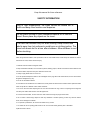
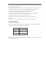
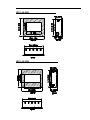
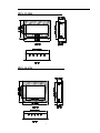
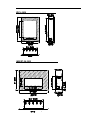
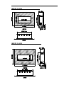
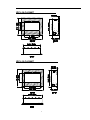
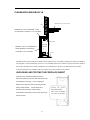
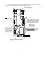
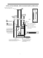
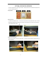
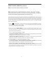
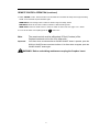
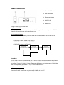
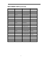
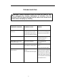
ELECTRIC FIREPLACES
SAFETY INFORMATION AND INSTALLATION MANUAL
ZECL-26-2923, ZECL-30-3226, ZECL-33-3624, ZECL-39-4134, ZECL-2923
INSERT-26-3825, INSERT-30-4026, INSERT-33-4230
ZECL-26-FLUSHMT, ZECL-30-FLUSHMT
Read these instructions completely before beginning installation. Failure to follow them could
cause a heater malfunction and result in serious injury and/or property damage.
WARNING: All electric heaters have hot or sparking parts inside. Do not use it in areas where
gasoline, paint or flammable liquids are stored.
WARNING: This heater is tested and listed for use only with the optional accessories listed in
these instructions. Use of optional accessories not specifically tested for this heater could void
the heater warranty and/or result in a safety hazard.
1
Keep this manual for future reference.
SAFETY INFORMATION
Due to high temperatures, the insert should be located out of
traffic and away from furniture and draperies.
Do not place clothing or other flammable material on or near the
insert. Never place any objects on the insert.
The insert can become very hot when running. Keep children and
adults away from hot surfaces to avoid burns or clothing ignition. The
insert will remain hot for a time after shutdown. Allow surfaces to cool
before touching.
When using electrical heaters, basic precautions, like the ones listed below, should always be followed in order to
reduce the risk of fire, electric shock and injury.
1. Read all instructions before using this heater.
2. Keep combustible materials, such as furniture, pillows, bedding, papers, clothes and curtains at least 3 feet from the
front of the heater; keep them away from sides and rear as well.
3. Always unplug heater when it’s not in use.
4. Do not operate the fireplace insert if it has a damaged cord or plug, after it has malfunctioned, or if the unit has been
dropped or damaged in any way.
5. Do not use the heater outdoors.
6. This heater is not intended for use in bathrooms, laundry areas and similar indoor locations. Never place the heater
where it may fall into a bathtub or other water containers.
7. Do not run the cord under carpeting. Do not cover the cord with throw rugs, runners or anything else. Arrange the
cord away from traffic areas where it could be tripped over.
8. To disconnect the heater, turn the controls to "OFF" before removing the plug from the outlet.
9. Do not insert or allow foreign objects to enter any ventilation or exhaust opening, as this may cause an electric
shock, fire or damage to the heater.
10. To prevent a possible fire, do not block air intakes in any manner.
11. A heater has hot or sparking parts inside. Do not use it in areas where gasoline, paint or flammable
liquids are used or stored.
2
12. Use this heater only as described in this manual. Any other use not recommended by the manufacturer may cause
fire, electric shock or injury to persons.
13. Avoid the use of an extension cord because the extension cord may overheat and cause a fire. If you have to use
an extension cord, the cord should be No. 14 AWG minimum size and rated not less than 1875 WATTS.
14. Always use a properly grounded, protected (fuse or circuit breaker), and polarized outlet.
15. Always use ground fault protection where it is required by electrical codes.
16. Always disconnect the power before performing any cleaning, maintenance or relocation of the heater.
17. To prevent a possible fire, do not burn wood or other materials in this heater.
18 To prevent electric shock or fire, always use a certified electrician, should new circuits or outlets
be required.
19. When transporting or storing the heater, keep it in a dry place, free from excessive vibration.
LISTING APPROVALS
This heater has been tested in accordance with the CSA Standards for fixed and location-dedicated electric room
heaters in the United States. All components are UL or CSA safety certified.
Voltage:
120 AC,
Hz:
60
Watts:
1500
Amps:
15
Note: This heater must be electrically wired and grounded in accordance with local codes or, in the absence of local
codes, with National Electric Code.
3
ZECL-26-2923
ZECL-30-3226
4
ZECL-33-3624
ZECL-39-4134
5
ZECL-2939
INSERT-26-3825
6
INSERT-30-4026
INSERT-33-4230
7
ZECL-26-FLUSHMT
ZECL-30-FLUSHMT
8
LOCATING THE FIREPLACE INSERT
WARNING: Never locate this heater where it may fall into a bathtub or
any water container.
NOTICE: All clearances must be maintained to combustibles.
Illustrations throughout these instructions reflect typical installations
and are for design purposes only. Actual installations may vary slightly
due to individual preferences.
Heater must be placed so it remains level (use included level to verify). Leveling bolts are provided
on the base of the fireplace insert to insure proper leveling.
WARNING:
RISK OF FIRE. MAINTAIN ALL SPECIFIED CLEARANCES
TO COMBUSTIBLES. FAILURE TO COMPLY WITH THESE
INSTRUCTIONS MAY CAUSE A FIRE OR CAUSE THE APPLIANCE TO
OVERHEAT. ENSURE ALL CLEARANCES (I.E. BACK, SIDE, TOP, VENT
MANTEL, FRONT, ETC.) ARE CLEARLY MAINTAINED.
APPLIANCE GRILLS (VENTS) LOCATED ON THE FRONT AND BACK OF THIS
ELECTRIC APPLIANCE CANNOT IN ANY WAY BE COVERED AS IT MAY
CREATE A FIRE HAZARD.
WHEN USING PAINT OR LACQUER TO FINISH THE AREA ABOVE THE INSERT, THE PAINT
OR LACQUER MUST BE HEAT RESISTANT TO PREVENT DISCOLORATION.
9
CLEARANCES WHEN BUILT-IN
MANTEL(maximum 12" (305mm) deep
WALL
MINIMUM 3/8" (10mm) CLEARANCE TO TOP
2"[50.8 mm]
OF APPLIANCE( combustible or non-combustible)
FRONT GLASS
MINIMUM 1" (25.4mm) CLEARANCE TO
APPLIANCE
SIDE VIEW
SIDES AND BACK OF APPLIANCE
(combustible or non-combustible)
FLOOR
The fireplace insert may be placed within a framed enclosure that is level, dry, and capable of supporting the weight of the appliance
and front glass. It may be placed directly on wood or a non-combustible surface (not on linoleum or carpet). The minimum clearance
from the top of the appliance to a mantel (combustible or non-combustible) is 2" (50.8mm). The sides and back must maintain
1" (25.4mm) clearance to any material. The top must maintain a 3/8" (10mm) clearance to any material.
UNPACKING AND TESTING THE FIREPLACE INSERT
Carefully remove the fireplace insert from the box.
Remove the packing screws from both sides of the insert
(see illustration to the right).
Prior to installing the
fireplace insert, plug the unit into a 120-volt grounded
outlet and test operation. Test all aspects of its
operation (manual switches, remote, display
characteristics and heater) to make sure all components
operate correctly.
10
INSTALLATION
CAUTION: The unit's power supply cord must be connected to a properly
grounded and protected 120-volt outlet. Always use ground fault protection where
required by the electrical code.
WARNING - RISK OF FIRE! To prevent a possible fire, do not block the grills,
louvers, or air openings on the fireplace insert in any manner.
WARNING - RISK OF FIRE! The power cord must not be pinched or placed
against a sharp edge. Secure the cord to avoid tripping or snagging thus reducing
the risk of fire, electric shock or personal injury. Do not run the cord under
carpeting. Do not cover the cord with throw rugs, runners or similar items.
Arrange the cord away from traffic areas where it could be tripped over.
This insert must be installed into an existing masonry or zero-clearance (metal) fireplace.
Select a suitable location that is not susceptible to moisture and is away from drapes, furniture and high traffic areas.
Note: Follow all national and local electrical codes.
11
INSTALLATION OVERVIEW – MASONRY FIREPLACES
Cover plate is required if chimney
does not have suitable rain cap.
one
Silic
2” (50mm) Minimum
HINT:
Close and seal the damper
to prevent air infiltration.
Attach the "This fireplace has been altered..." plate
to the fireplace (use two screws or other suitable
method). You may wish to place it in a location
where it will be covered by the surround glass.
HINT:
Paint the interior of the
fireplace with latex paint to
prevent fireplace odors
from entering the home.
Use one of the rear screws
on the insert to secure the
included tie-down bracket to
the fireplace. Once in place,
secure the bracket to the
fireplace floor to prevent the
insert from tipping. Secure
brackets to both sides.
The surround glass extends 1"
below the base of the insert.
A Code-Conforming (jacketed, grounded) receptacle
may be placed within the fireplace. Do not place it above
the fireplace insert.
12
Leveling Bolts
INSTALLATION OVERVIEW – ZERO-CLEARANCE (METAL) FIREPLACES
Cover plate is required if chimney
does not have suitable rain cap.
one
Silic
The log shelf,
screen, and doors
(if present) must
be removed.
2” (50mm)
Minimum
HINT:
Close and seal the damper
to prevent air infiltration.
HINT:
Paint the interior of the
fireplace with latex paint to
prevent fireplace odors
from entering the home.
Attach the "This fireplace has been
altered..." plate to the fireplace (use
two screws or other suitable
method). You may wish to place it in
a location where it will be covered by
the surround glass.
Use one of the rear screws
on the insert to secure the
included tie-down bracket to
the fireplace. Once in place,
secure the bracket to the
fireplace floor to prevent the
insert from tipping. Secure
brackets to both sides.
The surround glass extends 1"
below the base of the insert.
Leveling Bolts
A Code-Conforming (jacketed, grounded)
receptacle may be placed within the fireplace. Do
not place it above the fireplace insert.
13
If the firebox steps down greater than
1", place shims (plywood, tile, etc.)
under the leveling bolts to provide
adequate leveling.
OPTIONAL DECORATIVE INTERIORS
This insert is shipped with an under-lit log pre-installed. Glowing embers are also included with the fireplace insert
if you want a different appearance.
Glowing Embers
Harvest Moon
Clear
Sun Tea
Removing The Log
The under-lit log is shipped in place. On newer units, the log has tabs on each side that hold it in place. Remove
the black interior side panel (or carefully remove the tabs) to remove the log set. This is done by removing the two
screws holding the panel in place.
Installing the Glowing Embers
Pour the glowing embers onto the tray as shown below.
find most appealing.
14
Feel free to use the combination of glowing embers you
OPERATING INSTRUCTIONS
REMOVING THE SURROUND GLASS
Before removing the surround glass, make sure to have a suitable location to place the surround glass once it is
removed. Do not place the glass on sharp or uneven areas that may chip or damage the tempered glass. Use both
hands to lift the surround glass directly up. The hooks on the glass will disengage from the pins that protrude from
the side of the insert.
REMOTE CONTROL OPERATION
Power switch is
located behind the
surround glass –
MAKE SURE IT IS
TURNED ON.
1. For the remote to function make sure the heater is plugged in and main power switch is turned on.
15
REMOTE CONTROL OPERATION (continued)
Note. The remote control requires 2 AA batteries (not included).
Note: The heater may release a slight odor the first time it is turned on.
This is normal.
The heating
elements inside the heater will burn off any accumulated oils or dust during initial heating. This may also
occur when dust accumulates on the heating elements over periods of non-use.
2. When operating the remote make sure to point the remote at the center of the fireplace insert. Each time you press
a button on the remote the LED indicator on the top right of the remote should blink and the fireplace insert will “BEEP”.
If the LED fails to blink check the batteries. It takes up to one second for the fireplace insert to respond to the
transmitter. DO NOT PRESS THE BUTTONS MORE THAN ONCE within two seconds. This allows the fireplace
insert to respond to the remote.
3. Power on
button: The power – on button at top left corner of the remote is the main ON/ OFF power button.
This will turn off all the functions (heater and display). If you turn the fireplace insert OFF, then ON, the fireplace
insert will return to its last heater and display settings.
4. Flame Power On button ” DISPLAY ON OFF ”: This button controls both the ember and flame effect. Once the
flame effect is ON use the + and – buttons as explained below to adjust the flame brightness as desired. Press this
button again to turn OFF the flame effect.
a. The – or + buttons control the brightness of EMBER.
To increase the brightness of ember bed, press and release the + button. Each time you press this button
the brightness will increase small amount, until the maximum is reached.
To decrease the brightness of ember bed, press and release the – button. Each time you press this button
the brightness will decrease a small amount, until the minimum brightness is reached.
b. The FLAME INTENSITY– or + buttons control the brightness of
FLAME.
To increase the brightness / flame Intensity, press and release the + button.
Each time you press this
button the brightness will increase by a small amount, until the maximum is reached.
To decrease the brightness / flame Intensity, press and release the – button. Each time you press this
button the brightness will decrease by small amount, unitl the minimum brightness is reached. You can mix the
ember and the flame to create a realistic flame effect.
16
REMOTE CONTROL OPERATION (continued)
5. Heater " ON/OFF " button: Press this button to turn the heater ON. The heater will always start at high heat setting
1500W. To turn the heater off press this button again.
HIGH button: Press the high button to switch the heater to high heat setting 1500W.
LOW button: Press the low button to switch the heater to LOW heat setting 750W.
TEMP button: Press the TEMP. button to switch the heater to AUTO mode. See page 15 for details.
6. To turn off the heater unit completely press the
button once.
Note:
The remote control must be within about 20 feet (6 meters) of the
fireplace insert and not too far off to either side.
Important!
If the flame does not activate after the POWER ON/OFF button is pressed, press the
DISPLAY ON/OFF button to activate the flame. If the flame does not appear, press the
POWER ON/OFF button again.
WARNING: Before undertaking maintenance unplug the fireplace insert.
17
DIRECT OPERATION
1. Power ON/OFF switch
2. Heat control button
3. Flame control button
4. HEATER LED
5. POWER LED
Plug the heater into a suitable outlet.
1) “Power ON/OFF”
Set this switch to position I to turn the product ON. Setting it to O to turn the product OFF.
POWER LED will be lit when the fireplace insert is on.
The
2) “Heat control button”
Press the HEAT button repeatedly to set the heater to the desired heat set. The HEATER LED will
indicate the current setting for the heater as shown below:
HEATER LED = Red = 1500W HEAT OUTPUT
HEATER LED = Blue = 750W HEAT OUTPUT
HEATER LED = Purple = AUTO MODE
HIGH / 1500W
LOW / 750W
AUTO MODE
HEATER INDICATOR
HEATER INDICATOR
HEATER INDICATOR
OFF
Auto Mode
In this mode the heater will automatically turn on and off. When the room temperature drops below
71° F (22° C) the heater will turn on to the high heat setting (1500 watt). When the room temperature
is between 71° and 77° F (22-25° C) the heater output will switch to the low heat setting (750W). When
the room temperature goes above 77° F (25° C) the heater will turn off.
3) “Flame control button”
Press "Flame" button to adjust the flame intensity and ember bed brightness.
Press the "FLAME" control button to cycle through LO, MED, HI and OFF.
18
CLEANING AND MAINTENANCE
WARNING: Always disconnect the power and allow the heater to cool
before performing any cleaning, maintenance or relocation. Turn the
controls to OFF and remove the plug from the outlet or turn off the circuit
breaker before attempting any cleaning.
FRONT GLASS
1. Remove dust by buffing lightly with a clean dry cloth.
2. To remove fingerprints or other marks, the glass can be cleaned with a damp cloth using a good quality household
glass cleaner. The glass should be completely dried with a lint free cloth or paper towel.
3. In the event of glass breakage, vacuum all remaining glass pieces with a shop vac. DO NOT VACUUM WHILE THE
PIECES ARE HOT. Replace glass only with replacement parts made specifically for this heater. Never substitute
material.
REPLACEMENT PARTS
5
6
1
11
7
8
3
2
12
9
4
10
13
14
19
REPLACEMENT PARTS ( continued)
REF NO
PART NO.
DESCRIPTION
1
602030C
HEATER ASSEMBLY
2
601086C
CIRCULT BOART
3
301506
REMOTE RECEIVER
4
385506
3W LED ASSEMBLY
5
LED-M1-10
LED STRIP FOR FLAME
6
LED-M-2
LED STRIP FOR FLAME
7
LED-M2-10
LED STRIP FOR LOG
8
LED-M3-2
LED STRIP FOR LOG
9
LED-M1-12
LED STRIP FOR EMBER
10
LED-M-12
LED STRIP FOR EMBER
11
10105031B
REMOTE
12
10101201
FLAME MOTOR
13
10104010
SWITCH
14
10305506
ZECL/INSERT 26 LOG
10305507
ZECL/INSERT 30 LOG
10305508
ZECL/INSERT 33 LOG
10305509
ZECL 39 LOG
10305510
ZECL 2939 LOG
10701130
ZECL 26 FRONT GLASS
Not shown
10701131
INSERT 26 FRONT GLASS
Not shown
10701130B
ZECL 26 FLUSHMT FRONT GLASS
Not shown
10701132
ZECL 30 FRONT GLASS
Not shown
11701133
INSERT 30 FRONT GLASS
Not shown
10701132B
ZECL 30 FLUSHMT FRONT GLASS
Not shown
10701134
ZECL 33 FRONT GLASS
Not shown
10701135
INSERT 33 FRONT GLASS
Not shown
10701136
ZECL 39 FRONT GLASS
Not shown
11701137
ZECL 2939 FRONT GLASS
Not shown
15
20
REMARK
TROUBLE SHOOTING
WARNING: Always disconnect power and allow the heater to cool
before performing any cleaning, maintenance or relocation. Turn the
controls to OFF and remove the plug from the outlet or turn off the circuit
breaker before attempting any cleaning.
OBSERVED PROBLEM
POSSIBLE CAUSE
REMEDY
Fireplace insert turns off and will
Fireplace insert has overheated
Reset switch by turning main
not turn on
and safety device has caused
power switch off and waiting five
thermal switch to disconnect or
minutes, then turning it back on
home circuit breaker has opened
Log set and/or ember is dark
Wiring is loose
Inspect wiring for loose
connections and repair or
replace if necessary
Flame effect is not moving or
working abnormally
Remote control does not work
Flame motor is defective
Call a qualified service
technician
Low Batteries
Replace AA batteries in remote
Power switch is in OFF position
control
Turn on the main power switch
Heater does not provide heat
Thermal switch has been
Turn the unit off and unplug the
when turned on
tripped.
unit for five minutes. Plug back in
Circuit breaker has been tripped
and turn the unit on. If plug can
not be reached, turn off the circuit
breaker that supplies electricity to
the unit .Wait five minutes then flip
circuit breaker back on.
21
SERVICE HISTORY
22
23
24