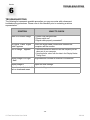
1
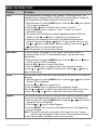
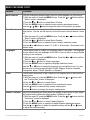
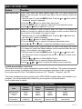
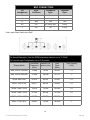
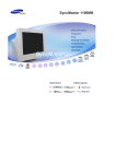
Solutions for Demanding Applications
VarTech Systems Inc.
Industrial CRT and Flat Panel Displays
VT19B-PW
19” Auto Sync Color Monitor
User’s Guide
Read these instructions completely before attempting to operate your new Color Display.
19” Fast Scan Series User Guide
150-062
TABLE OF CONTENTS
Sections
Page
1
Safety Warnings
2
FCC Statement
3
3
Installation
4
4
Controls
5-10
5
Pin Assignments
11-12
6
Troubleshooting Guide
13
7
Mechanical Drawings
14
Panel Mount Mechanical
15
Specifications
16
8
19” Fast Scan Series User Guide
1-2
150-062
Section
1
SAFETY WARNINGS
RISK OF ELECTRIC SHOCK!
DO NOT OPEN!!!
WARRANTY VOID IF CASING IS
REMOVED.
CAUTION: To reduce the risk of electric shock, do not remove cover (or back). No
user serviceable parts inside. Refer servicing to qualified technician.
WARNING
TO PREVENT FIRE OR SHOCK HAZARD, DO NOT EXPOSE THIS MONITOR TO RAIN OR
MOISTURE.
“HIGH VOLTAGE EXISTS ON THE CATHODE-RAY TUBE ANODE LEAD OF THIS MONITOR.
BEFORE SERVICING, DETERMINE THE PRESENCE OF HIGH VOLTAGE BY CONNECTING
THE H.V. METER BETWEEN THE ANODE OF CRT CAP AND CHASSIS ONLY.”
CAUTION
1. Keep monitor away from excessive dust, high temperature, moisture or direct sunlight.
2. Use in well ventilated area and do not cover ventilation openings.
3. Unauthorized modifications of this equipment or substitution or attachment of not shielded
connecting cable may cause excessive interference.
4. When the monitor is not in use for a long time, turn off power switch.
-119” Fast Scan Series User Guide
150-062
IMPORTANT SAFETY INSTRUCTIONS
Prior to using this product, please ensure that you have carefully followed all the procedures outlined
in the user’s manual for this product.
1.
2.
3.
4.
Read all of these instructions.
Save these instructions for later use.
Follow all warnings and instructions marked on the product.
Unplug this product from the wall outlet before cleaning. Do not use liquid cleaners or aerosol
cleaners. Use a damp cloth for cleaning.
5. Do not use this product near water.
6. Do not place this product on an unstable cart, stand or table. The product may fall causing
serious damage to the product.
7. Slots and openings in the cabinet and the back or bottom are provided for ventilation; to ensure
reliable operation of the product and to protect it from overheating, those openings must not be
blocked or covered. The openings should never be blocked by placing the product on a bed,
sofa, rug, or other similar surface. This product should never be placed near or over a radiator or
heat register. This product should not be placed in a built-in installation unless proper ventilation
is provided.
8. This product should be operated from the type of power source indicated on the marketing label.
If you are not sure of the type of power available, consult your dealer or local power company.
9. This product is equipped with a 3-wire grounding type plug, a plug having a third (grounding) pin.
This plug will only fit into a grounding-type power outlet. This is a safety feature. If you are unable
to insert the plug into the outlet, contact your electrician to replace your obsolete outlet. Do not
defeat the purpose of grounding type plug.
10. Do not allow anything to rest on the power cord. Do not locate this product where persons will
walk on the cord.
11. If an extension cord is used with this product, make sure that the total of the ampere ratings on
the products plugged into the extension cord do not exceed theextension cord ampere rating.
Also, make sure that the total of all products plugged into the wall outlet does not exceed 15
amperes.
12. Never push objects of any kind into this product through cabinet slots as they may touch
dangerous voltage points or short out parts that could result in a risk of fire or electric shock.
Never spill liquid of any kind on the product.
13. Do not attempt to service this product yourself, as opening or removing covers may expose you
to dangerous voltage points or other risks. Refer all servicing to service personnel.
14. Unplug this product from the wall outlet and refer servicing to qualified service personnel under
the following conditions:
A. When the power cord or plug is damaged or frayed.
B. If liquid has been spilled into the product.
C. If the product has been exposed to rain or water.
D. If the product does not operate normally when the operating instructions are followed.
Adjust only those controls that are covered by the operating instructions since improper
adjustment of other controls may result in damage and will often require extensive work by
a qualified technician to restore the product to normal operation.
E. If the product has been dropped or the cabinet has been damaged.
F. If the product exhibits a distinct change in performance, indicating a need for service.
-2-
19” Fast Scan Series User Guide
150-062
Section
2
FCC STATEMENT
FCC CLASS A STATEMENT
The equipment has been tested and found to comply with the limits for a Class A digital device,
pursuant to part 15 of FCC rules. These limits are designed to provide reasonable protection
against harmful interference in a business installation. This equipment generates, uses and can
radiate radio frequency energy and, if not installed and used in strict accordance with the
instructions, may cause harmful interference to radio communications. However, there is no
guarantee that interference will not occur in a particular installation. If this equipment does cause
harmful interference to radio or television reception, which can be determined by turning the
equipment off and on, the user is encouraged to try to correct the interference by one or more of the
following measure:
- Reorient or relocate the receiving antenna.
- Increase the separation between the equipment and the receiver.
- Connect the equipment into an outlet on a circuit different from
that to which the receiver is connected.
- Consult the dealer or an experienced radio/TV technician for help.
Shielded interconnected cables and shield power cords must be employed with this equipment to
insure compliance with the pertinent RF emission limits governing this device.
Changes or modifications not expressly approved by the manufacturer could void the user's
authority to operate the equipment.
-3-
19” Fast Scan Series User Guide
150-062
Section
3
INSTALLATION
INSTALLATION
1.Be sure your cable(s) are attached to the respective graphics board.
2.Set the BNC/D-SUB Source for video input
3.Connect the AC power cable to a properly grounded outlet.
4.Boot your computer. Turn on the monitor power. The power LED indicator should be
illuminated. If your monitor screen remains blank, check your video controller and computer
system.
-4-
19” Fast Scan Series User Guide
150-062
Section
4
CONTROLS
USER CONTROLS
Power button:
Use this button to turn the monitor on and off.
Power indicator:
The power LED is green when the display is in normal operation.
See Power management section for additional information.
CONTROL LOCATION
All controls are located on the rear of the monitor for the VT19B-PW.
VarTech
Button
Description
Function
EXIT BUTTON
Use this button to Exit the active menu or the OSD.
ADJUSTMENT
BUTTONS
These buttons allow you to highlight and adjust items in the
menu. All menus automatically save your adjustments 3 seconds
after you stop adjusting the setting.
MENU BUTTON
Use this button to open the OSD and activate a highlighted menu
item.
BRIGHTNESS
CONTRAST
To increase brightness press ×
To decrease brightness press Ø
To increase contrast ratio press Ö
To decrease contrast press Õ
AUTOMATIC SAVE
Whenever you open the on-screen menu and allow an adjustment window to remain active for
about 3 seconds without pressing another button, the monitor automatically saves any adjustments
you have made. These changes are saved into a user area in the monitor. User areas are reserved
according to the signal frequency from your computer. The monitor can save adjustments for up to
10 user modes. It has 8 factory preset or preload modes, one for each signal frequency as listed in
Display Modes Chart.
If you have made no adjustments, the on-screen menu disappears and the monitor does not save
anything. To exit without saving the changes you have made, press the EXIT button before the 3
seconds elapse.
-519” Fast Scan Series User Guide
150-062
DIRECT-ACCESS FEATURE : This feature can be accessed quickly, at the touch of one
button. When you finish making adjustments to a feature, push the EXIT button to turn off the menu
or allow the OSD to time out and disappear automatically.
Feature
Function
OSD Lock/Unlock
This function allows you to secure the current control settings so that they
cannot be inadvertently changed. You can unlock the OSD controls at any
time by using the same procedure.
Push and hold the MENU button for 10 seconds or more to Lock or to Unlock.
Information
The Information on this screen shows available
horizontal and vertical frequencies and display resolution.
1. With the menu off, push the DISP INFO button once to see information
about your monitor. The current Horizontal/Vertical frequencies received
from the computer or video board is displayed along the bottom.
2. Push the DISP INFO button once more to see the user defined timing mode.
3. Scroll down with the button to display the factory preset timings.
Note: These screens do not allow any changes to the settings; they are for
information only.
MENU FEATURES: The following features can all be accessed using you monitor’s on-screen
menu system. Follow the instructions below to adjust the features.
Once you are finished making adjustments to a feature, push the EXIT button to return to the main
menu, then push EXIT again to turn off the menu.
Feature
Function
Position
Follow these instructions to change the position of the monitor’s entire display.
1. With the menu off, push the MENU button. Push the Õ button or Ö button
until the “Position/Size” screen is displayed.
2. Push the Ø button or ×button to select Position.
3. Push the MENU button to open the Position adjustment screen.
Use the Ø and × buttons to change the vertical position of the monitor’s
viewing area; use the Õ and Ö buttons to change the horizontal position of
the monitor’s viewing area.
Size
Follow these instructions to change the size of the monitor’s entire display.
1. With the menu off, push the MENU button. Push the Õ button or Ö
button until the “Position/Size” screen is displayed.
2. Push the Ø button or × button to select Size.
3. Push the MENU button to open the Size adjustment screen.
Use the Ø and × buttons to change the vertical Size of the monitor’s
viewing area; use the Õ and Ö buttons to change the horizontal size of the
monitor’s viewing area.
-619” Fast Scan Series User Guide
150-062
MENU FEATURES CONT.
Feature
Function
Color
Color temperature is a measure of the “warmth” of the image colors. The
available range is between 5000 to 9300K. Follow these steps to change the
color temperature and adjust individual R,G,B color control.
1. With the menu off, push the MENU button. Push the Õ or Ö button until the
“Color” screen is displayed.
2. Use the × or Ø button to select Color1, Color2, or Color3.
3. Push the MENU button to open the “Color1”, “Color2”, or “Color3”
adjustment screen.
4. The current color temperature is shown highlighted between 9300 and
5000K. Use the Õ or Ö button to adjust the color temperature.
5. Adjust the color temperature as close to the desired temperature as
possible using only the Õ and Ö buttons. To fine tune the color hue, use
the × or Ø button to select R(ed), G(reen), or B(lue), then use the Õ and
Ö buttons until you reach the desired color.
Note: Recall does not reset the color settings.
Clear Moire
A “moire” pattern can appear on your screen, looking like a series of
concentric circles or arcs. To eliminate this pattern, use the clear moire
adjustments.
1. With the menu off, push the MENU button. Push the Õ button or Ö button
until the “Screen” OSD is displayed.
2. Use the × or Ø button to select Clear Moire.
3. Push the MENU button to open the clear moire adjustment screen.
Use the Õ or Ö button to adjust horizontal moire; use the × or Ø button to
adjust vertical moire.
Focus
Use the focus control when the image displayed on the screen is not sharp in
all areas.
1. With the menu off, push the MENU button. Push the Õ or Ö button until the
“Screen” OSD is displayed.
2. Push the × or Ø button to select Focus.
3. Push the MENU button to open the Focus adjustment screen.
Use the Õ or Ö button to adjust focus along the left and right areas of the
screen; use the × or Ø button to adjust the center area of the screen.
Degauss
The Degauss feature will remove color impurities caused by magnetic fields.
Do not use the Degauss feature more than once within a 30-minute period.
1. With the menu off, push the MENU button. Push the Õ or Ö button until the
“Advanced” screen is displayed.
2. Push the × or Ø button to select Degauss.
3. Push the MENU button to execute the Degauss function. The degaussing
screen will appear.
Note: The monitor may buzz momentarily, the image colors may change
and the image will jiggle for a few seconds. These effects are normal.
4. After a few seconds, the degauss main menu will return.
-7-
19” Fast Scan Series User Guide
150-062
MENU FEATURES CONT.
Feature
Function
Menu Position
You can change the position where the OSD menu appears on your monitor.
1. With the menu off, push the MENU button. Push the Õ or Ö button until the
“Menu” screen is displayed.
2. Push the × or Ø button to select Menu Position.
3. Push the MENU button to open the menu position adjustment screen.
Use the Õ, Ö, × or Ø button to place the menu in the position you prefer.
Menu Duration
The menu will automatically turn off if no adjustments are made for a certain
time period. You can set the amount of time the menu will wait before it turns
off.
1. With the menu off, push the MENU button. Push the Õ or Ö button until the
“Menu” screen is displayed.
2. Push the × or Ø button to select Menu Duration.
3. Push the MENU button to open the menu duration selection screen.
Use the Õ or Ö buttons to select 3,7,10,20, or 50 seconds. 10 seconds is the
default value.
Languages
Follow these steps to change the language used in the menu. The language
chosen affects only the language of the OSD. It has no effect on any software
running on the computer.
1. With the menu off, push the MENU button. Push the Õ or Ö button until the
“Menu” screen is displayed.
2. Push the × or Ø button to select Languages.
3. Push the MENU button to open the language selection screen.
Use the × or Ø button to select the language you would like to use. You can
choose one of ten languages (English, Polish, Magyar, Russian, Swedish,
Portuguese, Italian, French, Spanish, or German).
Zoom
Follow these instructions to get a close-up or a longshot view of the monitor’s
viewing area.
1. With the menu off, push the MENU button. Push the Õ or Ö button until
the “Position/Size” screen is displayed.
2. Push the × or Ø button to select Zoom.
3. Push the MENU button to open the Zoom adjustment screen.
Use the Õ button to decrease the screen viewing area.
Use the Ö button to enlarge the screen viewing area.
Parallel / Rotation
Adjust the parallelogram setting when the display is leaning left or right; adjust
the rotation setting when the entire display is tilted left or right.
1. With the menu off, push the MENU button. Push the Õ or Ö button until the
“Geometry” screen is displayed.
2. Push the × or Ø button to select Parallel/Rotation.
3. Push the MENU button to open the Parallel/Rotation adjustment screen.
Use the Õ or Ö button to adjust the parallel setting; use the × or Ø button
to adjust the rotation setting.
-8-
19” Fast Scan Series User Guide
150-062
MENU FEATURES CONT.
Feature
Function
Pincushion /
Trapezoid
Adjust the pincushion setting when the sides of the display are bowed in or
bowed out; adjust the trapezoid setting when the top or bottom of the display
is too large or small.
1. With the menu off, push the MENU button. Push the LEFT button or RIGHT
button until the “Geometry” screen is displayed.
2. Push the UP button or DOWN button to select Pincushion/Trapezoid.
3. Push the MENU button to open the Pincushion/Trapezoid adjustment
screen.
Use the LEFT button or RIGHT button to adjust the pincushion setting; use
the UP button or DOWN button to adjust the trapezoid setting.
Pinbalance
Adjust the Pinbalance setting when the sides of the display are bowed
towards the left or right.
1. With the menu off, push the MENU button. Push the LEFT button or
RIGHT button until the “Geometry” screen is displayed.
2. Push the UP button or DOWN button to select Pinbalance.
3. Push the MENU Button to open the Pinbalance adjustment screen.
Use the LEFT button or RIGHT button to adjust the Pinbalance setting.
Linearity
Adjust the linearity setting when the display image is compressed at the left,
right or top, bottom.
1. With the menu off, push the MENU button. Push the LEFT button or
RIGHT button until the “Screen” OSD is displayed.
2. Push the UP button or DOWN button to select Linearity.
3. Push the MENU Button to open the Linearity adjustment screen.
Use the LEFT button or RIGHT button to adjust the vertical Linearity.
Recall
Use the recall feature to reset these monitor settings to their original levels:
Position, Size, Pincushion, Trapezoid, Parallelogram, Pinbalance, Rotation,
and Clear Moire.
1. With the menu off, push the MENU button. Push the LEFT button or RIGHT
button until the “Advanced” screen is displayed.
2. Push the UP button or DOWN button to select Recall.
3. Push the MENU button to open the Recall selection screen.
4. Use the LEFT button to select YES. If you don’t want to reset the monitor,
use the RIGHT button to select NO.
NOTE: If you have selected “YES”, all settings listed above will be reset. All
other settings will remain the same.
CAUTION: This operation resets all of the data in the user memory area for
the current timing signal.
User-Delete
Push and hold EXIT button for at least 5 seconds.
CAUTION: This operation resets all of the data in the user memory area. If
this occurs, you must Remake your user adjustments.
-9-
19” Fast Scan Series User Guide
150-062
MENU FEATURES CONT.
Feature
Function
Video Input Level
Some video cards use video signals higher than 1.0V which causes the
display to be very bright. For those video cards, use this feature to select the
1.0V Level.
1. With the menu off, push the MENU button. Push the Õ or Ö button until the
“Advanced” screen is displayed.
2. Push the × or Ø button to select Video Input Level.
3. Push the MENU button to open the Video Input Level selection screen.
Use the Õ or Ö button to select 0.7V or 1.0V.
PinBalance corner Adjust the Pinbalance corner correction when the sides of the display are
bowed in or bowed out; adjust the side pin balance corner correction when the
top or bottom of the display is too large or small.
1. With the menu off, push the MENU button. Push the Õ or Ö button until
the “Geometry” screen is displayed.
2. Push the × or Ø button to select Pinbalance Corner.
3. Push the MENU button to open the Pinbalance Adjustment screen.
Use the Õ, Ö , × or Ø button to adjust the Pinbalance corner corrections.
Sidepin corner
Adjust the Sidepin corner correction when the sides of the display are bowed
in or bowed out; adjust the Sidepin balance corner correction when the top or
bottom of the display is too large or small.
1. With the menu off, push the MENU button. Push the Õ or Ö button until
the “Geometry” screen is displayed.Push the × or Ø button to select Video
Input Level.
2. Push the × or Ø button to select SidePin Corner.
3. Push the MENU button to open the Sidepin Adjustment screen.
Use the Õ, Ö, × or Ø button to adjust the Sidepin corner corrections.
POWER MANAGEMENT FUNCTION
This monitor has a built-in power management system called PowerSaver. This power management
system saves energy by switching your monitor into a low-power mode when it has not been used
for a certain amount of time. The available modes are “On”, “Standby”, “Suspend”, and “Off”.
This power management system operates with a VESA DPMS compliant video card installed in your
computer. You use a software utility installed on your computer to set up this feature.
See the table below for details.
Power-Saving Function Mode
State
Normal
Operation
Standby
Mode
Suspend Mode Power Off Mode Position
Position A1
A2
Horizontal Sync
Vertical Sync
Video
Active
Active
Active
Inactive
Active
Blanked
Active
Inactive
Blanked
Inactive
Inactive
Blanked
Power
Consumption
130W (max)
110W(nom)
60W (nom)
Less than 15W
Less than 3W
-10-
19” Fast Scan Series User Guide
150-062
Section
PIN ASSIGNMENTS
5
HD15 Connector
15-Pin Connector
(Figure 1)
Pin No.
Cable Adapter
(Figure 2)
Separate
Composite
Sync on
Green
Apple
MacII
1
Red
Red
Red
GND-R
2
Green
Green
Green+Sync
Red
3
Blue
Blue
Blue
H/V Sync.
4
GND
GND
GND
Sense 0
5
DDC Return
DDC Return
DDC Return
Green
6
GND-R
GND-R
GND-R
GND-G
7
GND-G
GND-G
GND-G
Sense 1
8
GND-B
GND-B
GND-B
Reserved
9
Reserved
Reserved
Reserved
Blue
10
GND-sync./
Self-Raster
GND-sync/
Self-Raster
GND-Sync/
Self-Raster
Sense 2
11
GND
GND
GND
GND
12
DDC Data
DDC Data
DDC Data
V-Sync.
13
H-Sync.
H-Sync.
Not Used
GND-B
14
V-Sync.
Not Used
Not Used
GND
15
DDC Clock
DDC Clock
DDC Clock
H-Sync.
Figure 1: Female Type
Figure 2: Male Type
1
5
10
15
6
11
1
15
*Input Select Switch set to D-SUB
19” Fast Scan Series User Guide
-11-
150-062
BNC CONNECTORS
Pin
Assignment
SyncOn-Green
Composite
Sync.
Separate
Sync.
R
Red
Red
Red
G
Green+Sync.
Green
Green
B
Blue
Blue
Blue
H/V
NC
H/V Comp. Sync.
H-Sync.
V
NC
NC
V-Sync.
*Note: Input Select Switch set to BNC
TERMINATION SWITCHES
For Normal Operation, have the RGB termination switches set to 75 OHM.
For Loop-through Configuration set to HI Z position.
Display Mode
Horizontal
Frequency
(kHz)
Vertical Frequency (Hz)
Pixel
Clock
(MHz)
Sync Polarity
(H/V)
IBM, VGA2, 720x400
31.469
70.087
28.322
-/+
IBM, VGA3, 640x480
31.469
59.940
25.175
-/-
VESA, 800 x 600
53.674
85.061
56.250
+/+
VESA, 1024 x 768
68.677
84.997
94.500
+/+
VESA, 1280 x 1024
79.976
75.025
135.000
+/+
VESA, 1280 x 1024
91.146
85.024
157.500
+/+
VESA, 1600 x 1200
93.750
75.000
202.500
+/+
MAC. 1152 x 870
68.681
75.062
100.000
-/-
-12-
19” Fast Scan Series User Guide
150-062
Section
6
TROUBLESHOOTING
TROUBLESHOOTING
The following list represents possible anomalies you may encounter with subsequent
troubleshooting procedures. Please refer to this checklist prior to contacting a service
representative.
SYMPTOM
WHAT TO CHECK
There is no screen image
1. Power cord disconnected?
2. Power switch on?
3. Signal cable properly connected?
“No Signal, Check Signal
Cable” appears
Check the signal cable connections between the
computer and the monitor.
“Out of Range” appears
1. Check the maximum resolution and the frequency on the
video port of your computer.
2. Compare these values with the data in the Display Modes
Timing Chart
Display image is too light
or dark
Brightness and contrast at minimum or maximum?
Display image is
Adjust the Size settings.
The colors are distorted with Activate the Degauss feature.
dark or shadowed areas
-1319” Fast Scan Series User Guide
150-062
Section
8
SPECIFICATIONS
ENGINEERING SPECIFICATIONS
CRT Size
19”
Video Bandwidth
250MHz dot clock
Dot Pitch
.20mm
Active Display Area
13.85” x 10.39” / 351.79mm x 263.91mm
Power Source
90-265VAC @50/60Hz
Power Consumption
120 Watts maximum
Scan Frequency
Horizontal: 30 to 96kHz
Vertical: 50 to 160Hz
Video Bandwidth
250mHz
Video Input Connectors
5BNC or HD15
Resolution Capabilities
VGA to UXGA
Video Input Signal
Analog video 0.7 Vpp positive at 75 Ω
Sync Input Signal
Separate sync: TTL Level, positive or negative
Composite sync: TTL Level, positive or negative
Sync-on-green: Composite sync 0.3 Vpp negative
(Video 0.7 Vpp positive)
Temperature
Operating: 0 to 50ºC
Storage: -20 to 60ºC
Humidity
Operating: 10 to 80% NC
Storage: 5 to 95% NC
NOTE:
This monitor automatically returns to normal operation when horizontal and vertical sync return. This occurs when you move
the
computer’s mouse or press a key on the keyboard.
This monitor is EPA ENERGY STAR® compliant and NUTEK compliant when used with a computer equipped with VESA
DPMS functionality.
For energy conservation, turn your monitor OFF when it is not needed,
or when leaving it unattended for long periods.
-1619” Fast Scan Series User Guide
150-062
VARTECH SYSTEMS INC.
HEADQUARTERS
11529 Sun Belt Ct.
Baton Rouge, Louisiana 70809
Toll-Free: 800.223.8050
International Phone: 001.225.298.0300
Fax: 225.297.2440
E-mail: [email protected]
www.vartechsystems.com
19” Fast Scan Series User Guide
150-062-001
12.24.03
150-062