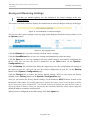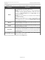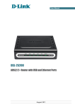
1
User Manual
DSL-2540U
ADSL/Ethernet Router with Built-in Switch
July 2012
DSL-2540U ADSL/Ethernet Router with Built-in Switch
User Manual
Contents
Chapter 1. Introduction..........................................4
Contents and Audience.......................................................4
Conventions.................................................................4
Document Structure..........................................................4
Chapter 2. Overview..............................................5
General Information.........................................................5
Specifications..............................................................6
Product Appearance..........................................................9
Front Panel...............................................................9
Back Panel...............................................................10
Delivery Package...........................................................11
Safety Instructions........................................................11
Chapter 3. Installation and Connection..........................12
Before You Begin...........................................................12
Connecting to PC...........................................................13
PC with Ethernet Adapter.................................................13
Obtaining IP Address Automatically in OS Windows XP......................13
Obtaining IP Address Automatically in OS Windows 7.......................16
Connecting to Web-based Interface..........................................21
Saving and Restoring Settings..............................................24
Chapter 4. Configuring via Web-based Interface..................25
Wizards....................................................................25
Internet Setup Wizard....................................................25
PPPoE or PPPoA Connection..............................................26
IPoA or Static IP Connection...........................................30
Dynamic IP Connection..................................................33
Bridge Connection......................................................36
Site Setup Wizard........................................................38
Status.....................................................................39
Network Statistics.......................................................39
DSL Status...............................................................40
WAN Status...............................................................41
DHCP.....................................................................42
Routing Table............................................................43
LAN Clients..............................................................44
Net........................................................................45
WAN......................................................................45
Creating ADSL WAN Connection...........................................46
Creating Ethernet WAN Connection.......................................52
LAN......................................................................56
Page 2 of 86
DSL-2540U ADSL/Ethernet Router with Built-in Switch
User Manual
Advanced...................................................................58
UPnP.....................................................................58
Interface Grouping.......................................................59
DDNS.....................................................................61
DNS......................................................................62
Routing..................................................................63
ADSL.....................................................................65
Remote Access............................................................66
Firewall...................................................................68
IP Filters...............................................................68
Virtual Servers..........................................................71
DMZ......................................................................73
Application Rules........................................................74
MAC Filter...............................................................76
Control....................................................................78
URL Filter...............................................................78
System.....................................................................80
Administrator Password...................................................80
Configuration............................................................81
System Log...............................................................82
Firmware Upgrade.........................................................84
NTP Client...............................................................85
Chapter 5. Abbreviations and Acronyms...........................86
Page 3 of 86
DSL-2540U ADSL/Ethernet Router with Built-in Switch
Introduction
User Manual
CHAPTER 1.
INTRODUCTION
Contents and Audience
This manual describes the router DSL-2540U and explains how to configure and operate it.
This manual is intended for users familiar with basic networking concepts, who create an in-home
local area network, and system administrators, who install and configure networks in offices.
Conventions
Example
!
Description
text
The body text of the manual.
Before You Begin
A reference to a chapter or section of this manual.
“Quick Installation Guide”
A reference to a document.
Change
A name of a menu, menu item, control (field, checkbox, dropdown list, button, etc.).
192.168.1.1
Data that you should enter in the specified field.
Information
An important note.
Document Structure
Chapter 1 describes the purpose and structure of the document.
Chapter 2 gives an overview of the router's hardware and software features and describes its
appearance and the package contents, and provides safety instructions.
Chapter 3 explains how to install the router DSL-2540U and configure a PC in order to access its
web-based interface.
Chapter 4 describes all pages of the web-based interface in detail.
Chapter 5 introduces abbreviations and acronyms used in this manual.
Page 4 of 86
DSL-2540U ADSL/Ethernet Router with Built-in Switch
Overview
User Manual
CHAPTER 2.
OVERVIEW
General Information
The DSL-2540U device is an affordable high-end ADSL/Ethernet router developed for home and
SOHO (Small Office/Home Office) networks. It provides fast and simple broadband access to the
Internet and a shared connection for multi users. The device allows accessing the Internet via ADSL
technology and via Ethernet technology.
DSL-2540U provides all the essentials for creating a secure high-speed wired network:
ADSL/ADSL2/ADSL2+ standards, Fast Ethernet standard, the built-in firewall, the QoS engine,
and numerous additional features.
The router is equipped with an ADSL port to connect to an ADSL line and 4 Ethernet ports to
connect workstations. Due to this feature, DSL-2540U represents a moderate-priced solution for
creating wired networks without an additional switch. In addition, any Ethernet port of the device
can be used to connect to a private Ethernet line.
The router DSL-2540U includes a built-in firewall. The advanced security functions minimize
threats of hacker attacks, prevent unwanted intrusions to your network, and block access to
unwanted websites for users of your LAN.
You can configure and manage the settings of the router DSL-2540U via the user-friendly webbased interface (the interface is available in several languages).
Page 5 of 86
DSL-2540U ADSL/Ethernet Router with Built-in Switch
Overview
User Manual
Specifications*
Interfaces:
•
ADSL: 1 RJ-11 port
•
LAN: 4 RJ-45 10/100BASE-TX Fast Ethernet ports with auto-MDI/MDIX.
ADSL Standards:
•
ADSL:
◦ full rate ANSI T1.413 Issue 2, ITU-T G.992.1 (G.dmt) Annex A, ITU-T G.992.2 (G.lite)
Annex A, ITU-T G.994.1 (G.hs).
•
ADSL2:
◦ ITU-T G.992.3 (G.dmt.bis) Annex A/L/M, ITU-T G.992.4 (G.lite.bis) Annex A.
•
ADSL2+:
◦ ITU-T G.992.5 Annex A/L/M.
WAN Connection Types:
•
ADSL:
◦ PPPoE
◦ PPPoA
◦ IPoA
◦ Static IP
◦ Dynamic IP
◦ Bridge.
•
Ethernet:
◦ PPPoE
◦ Static IP
◦ Dynamic IP
◦ Bridge.
* The device features are subject to change without notice. For the latest versions of the firmware and relevant
documentation, visit www.dlink.ru.
Page 6 of 86
DSL-2540U ADSL/Ethernet Router with Built-in Switch
Overview
User Manual
ATM/PPP Protocols:
•
Bridged and routed Ethernet encapsulation
•
VC-based or LLC-based multiplexing
•
ATM Forum UNI3.1/4.0 PVC (up to 8 PVCs)
•
ATM Adaptation Layer Type 5 (AAL5)
•
ITU-T I.610 OAM F4/F5 loopback
•
ATM QoS
•
PPP over ATM (RFC 2364)
•
PPP over Ethernet (PPPoE)
•
Keep-alive for PPP connections.
Network Protocols and Functions:
•
Static IP routing
•
NAT (Network Address Translation)
•
DHCP server/client/relay
•
DNS relay
•
DDNS
•
UPnP
•
Support of VLAN
•
IGMP proxy.
Firewall and Access Management Functions:
•
Network Address Translation (NAT)
•
Stateful Packet Inspection (SPI)
•
URL filter
•
Packet filtering (IP/ICMP/TCP/UDP)
•
Virtual servers
•
Prevention of DoS attacks
•
Intrusion detection system
•
DMZ
•
Port Triggering.
Page 7 of 86
DSL-2540U ADSL/Ethernet Router with Built-in Switch
Overview
User Manual
QoS:
•
Interface grouping
•
3 priority queues.
Configuration and Management:
•
Multilingual web-based interface for configuration and management
•
Access via TELNET
•
Firmware update via web-based interface
•
Saving/restoring configuration to/from file
•
Support of remote logging
•
Automatic synchronization of system time with NTP server.
LEDs:
•
Power
•
Status
•
LAN 1-4
•
DSL
•
Internet.
Power:
•
External power adapter DC 12V/0.5A
•
ON/OFF power switch
•
Reset to Factory Defaults button.
Page 8 of 86
DSL-2540U ADSL/Ethernet Router with Built-in Switch
Overview
User Manual
Product Appearance
Front Panel
Figure 1. Front panel view.
LED
Power
Status
Mode
Solid green
The router is powered on.
No light
The router is powered off.
Solid red
The router is in the crash recovery mode.
Blinking green
Traffic (Internet traffic) is passing through the router.
No light or solid green
A failure of the system.
Solid green
A device is connected to the port of the router (for the LAN
port configured as the WAN port: the router is connected to an
Ethernet line).
Blinking green
The relevant LAN port is active (upstream or downstream
traffic).
Solid green
DSL has been synchronized.
Blinking green
Detecting a carrier signal and synchronizing DSL.
No light
No carrier signal.
Solid green
A WAN connection (ADSL and/or Ethernet) is established.
Blinking green
Authorization is successful.
No light
The router is in the bridge mode or no WAN connection
(neither Ethernet nor ADSL) is established.
Solid red
An authorization failure.
LAN 1-4
DSL
Internet
Description
Page 9 of 86
DSL-2540U ADSL/Ethernet Router with Built-in Switch
Overview
User Manual
Back Panel
Figure 2. Back panel view.
Port
DSL
LAN 1-4
Description
A DSL port to connect the router to the telephone line.
4 Ethernet ports to connect Ethernet devices. One port can be used to connect to a
private Ethernet line.
A button to restore the factory default settings.
RESET
12V=0.5A
ON/OFF
To restore the factory defaults, push the button (with the device turned on), hold it
for 7-10 seconds, and then release the button.
Power connector.
A button to turn the router on/off.
Page 10 of 86
DSL-2540U ADSL/Ethernet Router with Built-in Switch
Overview
User Manual
Delivery Package
The following should be included:
•
Router DSL-2540U
•
Power adapter DC 12V/0.5A
•
RJ-11 telephone cable
•
Ethernet cable (CAT 5E)
•
Splitter
•
“Quick Installation Guide” (brochure).
The “User Manual” and “Quick Installation Guide” documents in Russian and English are
available on D-Link website (see ftp.dlink.ru/pub/ADSL/DSL-2540U/Description/).
!
Using a power supply with a different voltage rating than the one included will cause
damage and void the warranty for this product.
Safety Instructions
Place your router on a flat horizontal surface or mount the router on the wall (the mounting holes
are located on the bottom panel of the device). Make sure that the router is provided with sufficient
ventilation.
To prevent overheating, do not obstruct the ventilation openings of the router.
Plug the router into a surge protector to reduce the risk of damage from power surges and lightning
strikes.
Operate the router only from an electrical outlet with the correct power source as indicated on the
adapter.
Do not open the cover of the router. Otherwise any warranty will be invalidated.
Unplug the equipment before dusting and cleaning. Use a damp cloth to clean the equipment. Do
not use liquid/aerosol cleaners or magnetic/static cleaning devices.
Page 11 of 86
DSL-2540U ADSL/Ethernet Router with Built-in Switch
Installation and Connection
User Manual
CHAPTER 3.
INSTALLATION AND CONNECTION
Before You Begin
Please, read this manual prior to installing the device. Make sure that you have all the necessary
information and equipment.
Operating System
Configuration of the router DSL-2540U (hereinafter referred to as “the router”) is performed via the
built-in web-based interface. The web-based interface is available from any operating system that
supports a web browser.
Web Browser
The following web browsers are recommended: Windows Internet Explorer, Mozilla Firefox or
Opera.
For successful operation, JavaScript should be enabled on the web browser. Make sure that
JavaScript has not been disabled by other software (such as virus protection or web user security
packages) running on your computer.
NIC (Ethernet Adapter)
Any computer that uses the router should be equipped with an Ethernet adapter (NIC). If your
computer is not equipped with such a device, install an Ethernet adapter prior to using the router.
Page 12 of 86
DSL-2540U ADSL/Ethernet Router with Built-in Switch
Installation and Connection
User Manual
Connecting to PC
PC with Ethernet Adapter
1. Make sure that your PC is powered off.
2. Connect an Ethernet cable between any of Ethernet ports located on the back panel of the
router and the Ethernet port of your PC.
3. To connect the router to a DSL line: connect a phone cable between the DSL port of the
router and the ADSL OUT port of the splitter. Connect your phone to the PHONE port of
the splitter. Then connect another phone cable between a phone jack and the ADSL IN port
of the splitter.
4. To connect the router to an Ethernet line: connect the Ethernet cable between any of four
Ethernet ports located on the back panel of the router and the Ethernet line.
5. Connect the power cord to the power connector port on the back panel of the router, then
plug the power adapter into an electrical outlet or power strip.
6. Turn on the router by pressing the ON/OFF button on its back panel.
7. Turn on your PC and wait until your operating system is completely loaded.
Obtaining IP Address Automatically in OS Windows XP
1. Click the Start button and proceed to the Control Panel > Network and Internet
Connections > Network Connections window.
2. In the Network Connections window, right-click the relevant Local Area Connection
icon and select the Properties line in the menu displayed.
Figure 3. The Network Connections window.
Page 13 of 86
DSL-2540U ADSL/Ethernet Router with Built-in Switch
Installation and Connection
User Manual
3. In the Local Area Connection Properties window, on the General tab, select the
Internet Protocol (TCP/IP) line. Click the Properties button.
Figure 4. The Local Area Connection Properties window.
Page 14 of 86
DSL-2540U ADSL/Ethernet Router with Built-in Switch
Installation and Connection
User Manual
4. Select the Obtain an IP address automatically and Obtain DNS server address
automatically radio buttons. Click the OK button.
Figure 5. The Internet Protocol (TCP/IP) Properties window.
5. Click the ОК button in the connection properties window.
Now your computer is configured to obtain an IP address automatically.
Page 15 of 86
DSL-2540U ADSL/Ethernet Router with Built-in Switch
Installation and Connection
User Manual
Obtaining IP Address Automatically in OS Windows 7
1. Click the Start button and proceed to the Control Panel window.
2. Select the Network and Sharing Center section. (If the Control Panel has the category
view (the Category value is selected from the View by drop-down list in the top right
corner of the window), choose the View network status and tasks line under the
Network and Internet section.)
Figure 6. The Control Panel window.
Page 16 of 86
DSL-2540U ADSL/Ethernet Router with Built-in Switch
Installation and Connection
User Manual
3. In the menu located on the left part of the window, select the Change adapter settings
line.
Figure 7. The Network and Sharing Center window.
Page 17 of 86
DSL-2540U ADSL/Ethernet Router with Built-in Switch
Installation and Connection
User Manual
4. In the opened window, right-click the relevant Local Area Connection icon and select
the Properties line in the menu displayed.
Figure 8. The Network Connections window.
Page 18 of 86
DSL-2540U ADSL/Ethernet Router with Built-in Switch
Installation and Connection
User Manual
5. In the Local Area Connection Properties window, on the Networking tab, select the
Internet Protocol Version 4 (TCP/IPv4) line. Click the Properties button.
Figure 9. The Local Area Connection Properties window.
Page 19 of 86
DSL-2540U ADSL/Ethernet Router with Built-in Switch
Installation and Connection
User Manual
6. Select the Obtain an IP address automatically and Obtain DNS server address
automatically radio buttons. Click the OK button.
Figure 10. The Internet Protocol Version 4 (TCP/IPv4) Properties window.
7. Click the OK button in the connection properties window.
Now your computer is configured to obtain an IP address automatically.
Page 20 of 86
DSL-2540U ADSL/Ethernet Router with Built-in Switch
Installation and Connection
User Manual
Connecting to Web-based Interface
When you have configured your computer, you can access the web-based interface and configure
needed parameters (for example, create an interface to connect to the Internet, specify the settings
of the firewall, edit the password for the administrator account, etc.)
1. Start a web browser (see the Before You Begin section, page 12).
2. In the address bar of the web browser, enter the IP address of the router (by default, the
following IP address is specified: 192.168.1.1). Press the Enter key.
Figure 11. Connecting to the web-based interface of the DSL-2540U device.
3. On the opened page, enter the username (login) and password for the administrator account
(by default, the following username and password are specified: admin, admin). Then
click the Enter link.
Figure 12. The login page.
!
If the error “The page cannot be displayed” (or “Unable to display the page”/“Could not
connect to remote server”) occurs upon connecting to the web-based interface of the router,
make sure that you have properly connected the router to your computer.
!
For security reasons, it is strongly recommended to change the administrator password
upon initial configuration of the router. To do this, click the Configure manually button
and proceed to the System / Administrator password page.
Page 21 of 86
DSL-2540U ADSL/Ethernet Router with Built-in Switch
Installation and Connection
User Manual
After successful registration the router's quick settings page opens.
Figure 13. The quick settings page.
To configure connection to the Internet, click the Connect to internet button. After clicking the
button, the Internet Setup Wizard opens (see the Internet Setup Wizard section, page 25).
To configure access from the Internet to a web server located in your LAN, click the Host site
button. After clicking the button, the Site Setup Wizard opens (see the Site Setup Wizard section,
page 38).
To get back to the quick settings page from any Wizard or web-based interface menu section, leftclick the D-Link logo in the top left corner of the page.
To configure all parameters of the router independently without the Wizards, click the Configure
manually button.
After clicking the button the system statistics page opens. The page displays general information on
the router and its software (the version and the date of the firmware, the IP address of the device,
etc.), and data on the DSL connection state.
Figure 14. The system statistics page.
Page 22 of 86
DSL-2540U ADSL/Ethernet Router with Built-in Switch
Installation and Connection
User Manual
From the system statistics page you can proceed to the page for upgrading the router's firmware,
contact the technical support group, and proceed to the settings of the local interface.
To upgrade the firmware of the router, left-click the current firmware version (the right column of
the Firmware version line). After clicking the line, the System / Firmware upgrade page
opens (see the Firmware Upgrade section, page 84).
To contact the technical support group (to send an e-mail), left-click the support e-mail address (the
right column of the Support line). After clicking the line, the e-mail client window for sending a
new letter to the specified address opens.
To edit the router's local interface parameters, left-click the IP or MAC address of the local interface
(the right column of the LAN IP line or LAN MAC line correspondingly). After clicking the line,
the page for editing the LAN interface opens (see the LAN section, page 56).
The web-based interface of the router is multilingual. Select a needed language from the menu
displayed when the mouse pointer is over the Language caption. You can change the language of
the web-based interface in any menu item.
Figure 15. Changing the language of the web-based interface.
After selecting the language, the notification on unsaved changes will be displayed. Click the Save
button to save the current language of the web-based interface as the default language.
Page 23 of 86
DSL-2540U ADSL/Ethernet Router with Built-in Switch
Installation and Connection
User Manual
Saving and Restoring Settings
!
Note that you should regularly save the changes of the router's settings to the nonvolatile memory.
The router's web-based interface displays the notification on unsaved changes at the top of the page.
Figure 16. The notification on unsaved changes.
You can save the router's settings via the top-page menu displayed when the mouse pointer is over
the System caption.
Figure 17. The top-page menu.
Click the Reboot line if you have already saved the router's settings.
Click the Save&Reboot line to save new settings and immediately reboot the router.
Click the Save line to save new settings to the non-volatile memory and continue configuring the
device. Also you can save the device's parameters via the Save button on the System /
Configuration page.
Click the Backup line and follow the dialog box appeared to save the configuration (all settings of
the router) to your PC. Also you can save the router's configuration to your PC via the Backup
button on the System / Configuration page.
Click the Factory line to restore the factory default settings. Also you can restore the factory
defaults via the Factory button on the System / Configuration page.
Also you can restore the factory default settings via the hardware RESET button located on the
back panel of the router. Use a small paperclip to activate the button; insert it into the hole (with the
device turned on), push, and hold for 7-10 seconds. Release the button and wait until the router is
rebooted (about a minute). Now you can access the web-based interface of the router using the
default IP address, username and password.
When you have configured all needed settings, click the Logout line.
Page 24 of 86
DSL-2540U ADSL/Ethernet Router with Built-in Switch
Configuring via Web-based Interface
User Manual
CHAPTER 4. CONFIGURING
INTERFACE
VIA
WEB-BASED
Wizards
Internet Setup Wizard
To configure connection to the Internet, click the Connect to internet button.
Figure 18. Configuring connection to the Internet.
To create a new WAN connection, click the add new connection link.
Figure 19. The page for selecting the connection type.
On the opened page, select the needed choice of the radio button and click the Next button.
Page 25 of 86
DSL-2540U ADSL/Ethernet Router with Built-in Switch
Configuring via Web-based Interface
User Manual
PPPoE or PPPoA Connection
Figure 20. Configuring PPPoE WAN connection.
In the Name field, specify a name for the connection for easier identification and click the Next
button.
Figure 21. Configuring PPPoE WAN connection.
In the VPI field, specify the VPI. In the VCI field, specify the VCI.
From the Encapsulation Mode drop-down list, select a method of encapsulation.
In the Username field, enter your login, and in the Password and Password confirmation
fields – the password provided by your ISP.
If authorization is not required, select the Without authorization checkbox.
Page 26 of 86
DSL-2540U ADSL/Ethernet Router with Built-in Switch
Configuring via Web-based Interface
User Manual
If needed, specify additional settings for your PPPoE or PPPoA WAN connection.
Figure 22. Configuring PPPoE WAN connection.
Parameter
Service name
Authentication
algorithm
MTU
Description
Displayed for the PPPoE type only.
The name of the PPPoE authentication server.
Select a required authentication method from the drop-down list or
leave the AUTO value.
The maximum size of units transmitted by the interface.
Page 27 of 86
DSL-2540U ADSL/Ethernet Router with Built-in Switch
Configuring via Web-based Interface
User Manual
Parameter
Description
Keep Alive
Select the checkbox if you want the router to keep you connected to
your ISP even when the connection has been inactive for a specified
period of time. When the checkbox is selected, the LCP interval
and LCP fails fields are available. Specify the required values.
Dial on demand
Select the checkbox if you want the router to establish connection to
the Internet on demand. In the Maximum idle time field, specify a
period of inactivity (in seconds) after which the connection should
be terminated.
PPP IP extension
This option is used by some ISPs. Contact your ISP to clarify if this
checkbox needs to be enabled.
Use Static IP Address
Select the checkbox if you want to use a static IP address to access
the Internet. In the Static IP Address field displayed when the
checkbox is selected, specify a static IP address.
PPP debug
Select the checkbox if you want to log all data on PPP connection
debugging.
Displayed for the PPPoE type only.
PPPoE pass through
Select the checkbox if you want to allow PPPoE clients of
computers from your LAN to connect to the Internet through this
PPPoE connection of the router.
Click the Next button to continue.
If needed, change the connection settings available in the Miscellaneous section.
Figure 23. Configuring PPPoE WAN connection.
Page 28 of 86
DSL-2540U ADSL/Ethernet Router with Built-in Switch
Configuring via Web-based Interface
User Manual
Parameter
Description
Enable IGMP Multicast
Select the checkbox to allow multicast traffic from the external
network (e.g. video streaming) to be received.
NAT
Select the checkbox if you want one WAN IP address to be used for
all computers of your LAN.
Firewall
Select the checkbox to enable protection against ARP and DDoS
attacks.
Click the Next button to continue.
If needed, change the connection settings available in the VLAN section (the page is displayed for
the PPPoE type only).
Figure 24. Configuring PPPoE WAN connection.
Parameter
Description
Allow to create several
connections assigned
to this port
Select the checkbox to allow the router to use several untagged
connections.
Use VLAN
Select the checkbox to allow the router to use tagged VLAN
connections.
VLAN ID
An identifier for the VLAN. The field is displayed when the Use
VLAN checkbox is selected.
VLAN priority
A priority tag for the type of traffic transmitted. The field is
displayed when the Use VLAN checkbox is selected.
Click the Next button to continue.
After that the page displaying all specified settings opens. Click the Save button to create the
connection or the Back button to specify other settings.
After clicking the Save button, the quick settings page opens.
Page 29 of 86
DSL-2540U ADSL/Ethernet Router with Built-in Switch
Configuring via Web-based Interface
User Manual
IPoA or Static IP Connection
Figure 25. Configuring Static IP WAN connection.
In the Name field, specify a name for the connection for easier identification and click the Next
button.
Figure 26. Configuring Static IP WAN connection.
In the VPI field, specify the VPI. In the VCI field, specify the VCI.
From the Encapsulation Mode drop-down list, select a method of encapsulation.
Fill in the IP address and Netmask fields.
In the Gateway IP address field, enter the IP address of the gateway used by this WAN
connection.
Page 30 of 86
DSL-2540U ADSL/Ethernet Router with Built-in Switch
Configuring via Web-based Interface
User Manual
Click the Next button to continue.
If needed, change the connection settings available in the Miscellaneous section.
Figure 27. Configuring Static IP WAN connection.
Parameter
Description
Enable IGMP Multicast
Select the checkbox to allow multicast traffic from the external
network (e.g. video streaming) to be received.
NAT
Select the checkbox if you want one WAN IP address to be used for
all computers of your LAN.
Firewall
Select the checkbox to enable protection against ARP and DDoS
attacks.
Click the Next button to continue.
If needed, change the connection settings available in the VLAN section (the page is displayed for
the Static IP type only).
Figure 28. Configuring Static IP WAN connection.
Page 31 of 86
DSL-2540U ADSL/Ethernet Router with Built-in Switch
Configuring via Web-based Interface
User Manual
Parameter
Description
Allow to create several
connections assigned
to this port
Select the checkbox to allow the router to use several untagged
connections.
Use VLAN
Select the checkbox to allow the router to use tagged VLAN
connections.
VLAN ID
An identifier for the VLAN. The field is displayed when the Use
VLAN checkbox is selected.
VLAN priority
A priority tag for the type of traffic transmitted. The field is
displayed when the Use VLAN checkbox is selected.
Click the Next button to continue.
After that the page displaying all specified settings opens. Click the Save button to create the
connection or the Back button to specify other settings.
After clicking the Save button, the quick settings page opens.
Page 32 of 86
DSL-2540U ADSL/Ethernet Router with Built-in Switch
Configuring via Web-based Interface
User Manual
Dynamic IP Connection
Figure 29. Configuring Dynamic IP WAN connection.
In the Name field, specify a name for the connection for easier identification and click the Next
button.
Figure 30. Configuring Dynamic IP WAN connection.
In the VPI, specify the VPI. In the VCI field, specify the VCI.
From the Encapsulation Mode drop-down list, select a method of encapsulation.
If your ISP has provided its identifier, fill in the Vendor ID field.
Click the Next button to continue.
Page 33 of 86
DSL-2540U ADSL/Ethernet Router with Built-in Switch
Configuring via Web-based Interface
User Manual
If needed, change the connection settings available in the Miscellaneous section.
Figure 31. Configuring Dynamic IP WAN connection.
Parameter
Description
Enable IGMP Multicast
Select the checkbox to allow multicast traffic from the external
network (e.g. video streaming) to be received.
NAT
Select the checkbox if you want one WAN IP address to be used for
all computers of your LAN.
Firewall
Select the checkbox to enable protection against ARP and DDoS
attacks.
Click the Next button to continue.
If needed, change the connection settings available in the VLAN section.
Figure 32. Configuring Dynamic IP WAN connection.
Page 34 of 86
DSL-2540U ADSL/Ethernet Router with Built-in Switch
Configuring via Web-based Interface
User Manual
Parameter
Description
Allow to create several
connections assigned
to this port
Select the checkbox to allow the router to use several untagged
connections.
Use VLAN
Select the checkbox to allow the router to use tagged VLAN
connections.
VLAN ID
An identifier for the VLAN. The field is displayed when the Use
VLAN checkbox is selected.
VLAN priority
A priority tag for the type of traffic transmitted. The field is
displayed when the Use VLAN checkbox is selected.
Click the Next button to continue.
After that the page displaying all specified settings opens. Click the Save button to create the
connection or the Back button to specify other settings.
After clicking the Save button, the quick settings page opens.
Page 35 of 86
DSL-2540U ADSL/Ethernet Router with Built-in Switch
Configuring via Web-based Interface
User Manual
Bridge Connection
Figure 33. Configuring Bridge WAN connection.
In the Name field, specify a name for the connection for easier identification and click the Next
button.
Figure 34. Configuring Bridge WAN connection.
In the VPI field, specify the VPI. In the VCI field, specify the VCI.
From the Encapsulation Mode drop-down list, select a method of encapsulation.
Click the Next button to continue.
Page 36 of 86
DSL-2540U ADSL/Ethernet Router with Built-in Switch
Configuring via Web-based Interface
User Manual
If needed, change the connection settings available in the VLAN section.
Figure 35. Configuring Bridge WAN connection.
Parameter
Description
Allow to create several
connections assigned
to this port
Select the checkbox to allow the router to use several untagged
connections.
Use VLAN
Select the checkbox to allow the router to use tagged VLAN
connections.
VLAN ID
An identifier for the VLAN. The field is displayed when the Use
VLAN checkbox is selected.
VLAN priority
A priority tag for the type of traffic transmitted. The field is
displayed when the Use VLAN checkbox is selected.
Click the Next button to continue.
After that the page displaying all specified settings opens. Click the Save button to create the
connection or the Back button to specify other settings.
After clicking the Save button, the quick settings page opens.
Page 37 of 86
DSL-2540U ADSL/Ethernet Router with Built-in Switch
Configuring via Web-based Interface
User Manual
Site Setup Wizard
To create a virtual server for redirecting incoming Internet traffic to a specified IP address in the
LAN, click the Host site button.
Figure 36. The page for adding a virtual server.
On the opened page, you can specify the following parameters:
Parameter
Description
Name
Enter a name for the virtual server for easier identification. You can
specify any name.
Interface
Select a WAN connection to which this virtual server will be
assigned.
Private IP
Enter the IP address of the server from the local area network. To
choose a device connected to the router's LAN at the moment, select
the relevant value from the drop-down list located to the right of the
Private IP field (the field will be filled in automatically).
Remote IP
Enter the IP address of the server from the external network.
When needed settings are configured, click the Save button. After that you get to the quick settings
page.
Page 38 of 86
DSL-2540U ADSL/Ethernet Router with Built-in Switch
Configuring via Web-based Interface
User Manual
Status
The pages of this section display data on the current state of the router:
•
network statistics
•
DSL connection status
•
active WAN connections
•
IP addresses leased by the DHCP server
•
the routing table
•
data on devices connected to the router's network and its web-based interface.
Network Statistics
On the Status / Network statistics page, you can view statistics for all interfaces (connections)
existing in the system. For each connection the following data are displayed: state, IP address,
subnet mask and gateway (if the connection is established), MAC address, MTU value, and volume
of data received and transmitted (with increase of the volume the units of measurement are changed
automatically: byte, Kbyte, Mbyte, Gbyte).
Figure 37. The Status / Network statistics page.
Page 39 of 86
DSL-2540U ADSL/Ethernet Router with Built-in Switch
Configuring via Web-based Interface
User Manual
DSL Status
The information shown on the tabs of the Status / DSL status page can be used for
troubleshooting and diagnosing connection problems.
Figure 38. The Status / DSL status page.
Page 40 of 86
DSL-2540U ADSL/Ethernet Router with Built-in Switch
Configuring via Web-based Interface
User Manual
WAN Status
The Status / WAN status page displays active WAN connections.
Figure 39. The Status / WAN status page.
Page 41 of 86
DSL-2540U ADSL/Ethernet Router with Built-in Switch
Configuring via Web-based Interface
User Manual
DHCP
The Status / DHCP page displays the information on computers that have been identified by
hostnames and MAC addresses and have got IP addresses from the DHCP server of the device, as
well as the IP address expiration periods (the lease time).
Figure 40. The Status / DHCP page.
Page 42 of 86
DSL-2540U ADSL/Ethernet Router with Built-in Switch
Configuring via Web-based Interface
User Manual
Routing Table
The Status / Routing table page displays the information on routes. The table contains
destination IP addresses, gateways, subnet masks, and other data.
Figure 41. The Status / Routing table page.
Page 43 of 86
DSL-2540U ADSL/Ethernet Router with Built-in Switch
Configuring via Web-based Interface
User Manual
LAN Clients
On the Status / LAN clients page, you can view data on network devices connected to the router.
The page displays devices connected to the built-in switch of the router, and devices accessing the
web-based interface of the router.
Figure 42. The Status / LAN clients page.
For each device the following data are displayed: the IP address, the MAC address, and the
interface to which the device is connected.
Page 44 of 86
DSL-2540U ADSL/Ethernet Router with Built-in Switch
Configuring via Web-based Interface
User Manual
Net
In this menu you can configure basic parameters of the router's local area network and configure
connection to the Internet (a WAN connection).
WAN
On the Net / WAN page, you can create and edit connections used by the router.
Figure 43. The Net / WAN page.
To create a new connection, click the Add button. On the page displayed, specify the relevant
values.
To edit an existing connection, left-click the relevant line in the table. On the page displayed,
change the parameters and click the Save button.
To delete an existing connection, left-click the relevant line in the table. On the page displayed,
click the Delete button.
To use one of existing WAN connections as a default gateway, select the choice of the Default
gateway radio button located in the line corresponding to this connection.
Page 45 of 86
DSL-2540U ADSL/Ethernet Router with Built-in Switch
Configuring via Web-based Interface
User Manual
Creating ADSL WAN Connection
Figure 44. The page for creating a new connection. The General settings, ATM and VLAN sections.
Page 46 of 86
DSL-2540U ADSL/Ethernet Router with Built-in Switch
Configuring via Web-based Interface
User Manual
Parameter
Description
General settings
A type of network protocol to be used by the connection. Available
values:
Connection Type
Port
•
PPPoA
•
PPPoE
•
Static IP
•
Dynamic IP
•
IPoA
•
Bridge.
A physical interface to which the new connection will be assigned.
Leave the DSL(new) value to create a new interface at the physical
layer.
Name
A name for connection for easier identification.
Enable
Select the checkbox to enable the connection.
Direction
The direction of this connection.
ATM
VPI
Virtual Path Identifier. The valid range is from 0 to 250.
VCI
Virtual Circuit Identifier. The valid range is from 32 to 65535.
Encapsulation Mode
QoS
Select LLC or VC from the drop-down list.
A class of traffic for this connection.
UBR
(Unspecified Bit Rate): The UBR service is used for applications
that allow various delays and losses of packets. It is appropriate to
use the UBR service for text/data/image transfer applications, as
well as messaging, distribution, retrieval, and remote terminal
applications.
UBR With PCR
(Unspecified Bit Rate with Peak Cell Rate): The UBR service is
used for applications that allow various delays and losses of packets.
The Peak Cell Rate is a determining factor in how often cells are
sent in an effort to minimize lag or jitter caused by traffic
inconsistencies. When you select this value from the drop-down list,
Page 47 of 86
DSL-2540U ADSL/Ethernet Router with Built-in Switch
Configuring via Web-based Interface
User Manual
Parameter
Description
the Peak Cell Rate field is displayed. Specify a required value (in
cells per second).
CBR
(Constant Bit Rate): This service is used for applications that
require a constant data rate. It is mostly used for transferring
uncompressed audio and video, e.g. videoconferencing, interactive
audio (telephony), audio/video distribution (television, distance
education, e-shops), and retrieval (video-on demand, audio
libraries). When you select this value from the drop-down list, the
Peak Cell Rate field is displayed. Specify a required value (in
cells per second).
Non Realtime VBR
(Non-Real-time Variable Bit Rate): This service can be used for
transferring data that have critical response-time requirements, e.g.
air ticket booking, bank transactions, and process monitoring. When
you select this value from the drop-down list, the Peak Cell Rate,
Sustainable Cell Rate, and Maximum Burst Size fields are
displayed. Specify required values.
Realtime VBR
(Real-time Variable Bit Rate): This service is used for delaysensitive applications such as real time video. The Rt-VBR provides
higher network flexibility than the CBR service. When you select
this value from the drop-down list, the Peak Cell Rate,
Sustainable Cell Rate, and Maximum Burst Size fields are
displayed. Specify required values.
Page 48 of 86
DSL-2540U ADSL/Ethernet Router with Built-in Switch
Configuring via Web-based Interface
User Manual
The VLAN section is displayed for the PPPoE, Static IP, Dynamic IP, and Bridge connection
types.
Parameter
Description
VLAN
Allow to create several
connections assigned
to this port
Select the checkbox to allow the router to use several untagged
connections.
Use VLAN
Select the checkbox to allow the router to use tagged VLAN
connections.
VLAN ID
An identifier for the VLAN. The field is displayed when the Use
VLAN checkbox is selected.
VLAN priority
A priority tag for the type of traffic transmitted. The field is
displayed when the Use VLAN checkbox is selected.
The Miscellaneous section is displayed for all connection types except for Bridge.
Figure 45. The page for creating a new connection. The Miscellaneous section.
Parameter
Description
Miscellaneous
Enable IGMP Multicast
Select the checkbox to allow multicast traffic from the external
network (e.g. video streaming) to be received.
NAT
Select the checkbox if you want one WAN IP address to be used for
all computers of your LAN.
Firewall
Select the checkbox to enable protection against ARP and DDoS
attacks.
Page 49 of 86
DSL-2540U ADSL/Ethernet Router with Built-in Switch
Configuring via Web-based Interface
User Manual
The PPP section is displayed for the PPPoE and PPPoA connection types.
Figure 46. The page for creating a new connection. The PPP section.
Parameter
Description
PPP
Username
Without authorization
Password
Password confirmation
Service name
Authentication
algorithm
MTU
Keep Alive
A username (login) to access the Internet.
Select the checkbox if you don't need to enter a username and
password to access the Internet.
A password to access the Internet.
The confirmation of the entered password (to avoid mistypes).
Displayed for the PPPoE type only.
The name of the PPPoE authentication server.
Select a required authentication method from the drop-down list or
leave the AUTO value.
The maximum size of units transmitted by the interface.
Select the checkbox if you want the router to keep you connected to
your ISP even when the connection has been inactive for a specified
period of time. When the checkbox is selected, the LCP interval
and LCP fails fields are available. Specify the required values.
Page 50 of 86
DSL-2540U ADSL/Ethernet Router with Built-in Switch
Configuring via Web-based Interface
User Manual
Parameter
Description
Dial on demand
Select the checkbox if you want the router to establish connection to
the Internet on demand. In the Maximum idle time field, specify a
period of inactivity (in seconds) after which the connection should
be terminated.
PPP IP extension
This option is used by some ISPs. Contact your ISP to clarify if this
checkbox needs to be enabled.
Use Static IP Address
Select the checkbox if you want to use a static IP address to access
the Internet. In the Static IP Address field displayed when the
checkbox is selected, specify a static IP address.
PPP debug
Select the checkbox if you want to log all data on PPP connection
debugging.
Displayed for the PPPoE type only.
PPPoE pass through
Select the checkbox if you want to allow PPPoE clients of
computers from your LAN to connect to the Internet through this
PPPoE connection of the router.
The IP section is displayed for the Static IP, Dynamic IP and IPoA connection types.
Figure 47. The page for creating a new connection. The IP section.
Parameter
Description
IP
IP Address
Netmask
Gateway IP Address
Vendor ID
Displayed for the Static IP and IPoA types only.
Enter an IP address for this WAN connection.
Displayed for the Static IP and IPoA types only.
Enter a subnet mask for this WAN connection.
Displayed for the Static IP and IPoA types only.
Enter an IP address of the gateway used by this WAN connection.
Displayed for the Dynamic IP type only.
The identifier of your ISP. Optional.
When all needed settings are configured, click the Save button.
Page 51 of 86
DSL-2540U ADSL/Ethernet Router with Built-in Switch
Configuring via Web-based Interface
User Manual
Creating Ethernet WAN Connection
Prior to creating an Ethernet WAN connection, specify a LAN port that will be used as the WAN
port (see the Interface Grouping section, page 59).
Figure 48. The page for creating a new connection. The General settings and Ethernet sections.
Parameter
Description
General settings
A type of network protocol to be used by the connection. Available
values:
Connection Type
Port
•
PPPoE
•
Static IP
•
Dynamic IP
•
Bridge.
Select the value corresponding to the LAN port specified as the
WAN port.
Name
A name for connection for easier identification.
Enable
Select the checkbox to enable the connection.
Direction
The direction of this connection.
Ethernet
MTU
The maximum size of units transmitted by the interface.
MAC
A MAC address assigned to the interface.
Page 52 of 86
DSL-2540U ADSL/Ethernet Router with Built-in Switch
Configuring via Web-based Interface
User Manual
Parameter
Description
VLAN
(The section is displayed, if the VLAN MUX Mode or ServiceMUX Mode choice of the
Ethernet WAN type radio button is selected on the Advanced / Interface grouping page.)
Allow to create several
connections assigned
to this port
If the checkbox is selected, the router is able to use several untagged
connections.
Use VLAN
If the checkbox selected, the router is able to use tagged VLAN
connections.
VLAN ID
An identifier for the VLAN. The field is displayed when the Use
VLAN checkbox is selected.
VLAN priority
A priority tag for the type of traffic transmitted. The field is
displayed when the Use VLAN checkbox is selected.
The Miscellaneous section is displayed for all connection types except for Bridge.
Figure 49. The page for creating a new connection. The Miscellaneous section.
Parameter
Description
Miscellaneous
Enable IGMP Multicast
Select the checkbox to allow multicast traffic from the external
network (e.g. video streaming) to be received.
NAT
Select the checkbox if you want one WAN IP address to be used for
all computers of your LAN.
Firewall
Select the checkbox to enable protection against ARP and DDoS
attacks.
Page 53 of 86
DSL-2540U ADSL/Ethernet Router with Built-in Switch
Configuring via Web-based Interface
User Manual
The PPP section is displayed for the PPPoE connection type.
Figure 50. The page for creating a new connection. The PPP section.
Parameter
Description
PPP
Username
Without authorization
Password
Password confirmation
A username (login) to access the Internet.
Select the checkbox if you don't need to enter a username and
password to access the Internet.
A password to access the Internet.
The confirmation of the entered password (to avoid mistypes).
Service name
The name of the PPPoE authentication server.
Authentication
algorithm
Select a required authentication method from the drop-down list or
leave the AUTO value.
MTU
Keep Alive
The maximum size of units transmitted by the interface.
Select the checkbox if you want the router to keep you connected to
your ISP even when the connection has been inactive for a specified
period of time. When the checkbox is selected, the LCP interval
and LCP fails fields are available. Specify the required values.
Page 54 of 86
DSL-2540U ADSL/Ethernet Router with Built-in Switch
Configuring via Web-based Interface
User Manual
Parameter
Description
Dial on demand
Select the checkbox if you want the router to establish connection to
the Internet on demand. In the Maximum idle time field, specify a
period of inactivity (in seconds) after which the connection should
be terminated.
PPP IP extension
This option is used by some ISPs. Contact your ISP to clarify if this
checkbox needs to be enabled.
Use Static IP Address
Select the checkbox if you want to use a static IP address to access
the Internet. In the Static IP Address field displayed when the
checkbox is selected, specify a static IP address.
PPP debug
Select the checkbox if you want to log all data on PPP connection
debugging.
PPPoE pass through
Select the checkbox if you want to allow PPPoE clients of
computers from your LAN to connect to the Internet through this
PPPoE connection of the router.
The IP section is displayed for the Static IP and Dynamic IP connection types.
Figure 51. The page for creating a new connection. The IP section.
Parameter
Description
IP
IP Address
Netmask
Gateway IP Address
Vendor ID
Displayed for the Static IP type only.
Enter an IP address for this WAN connection.
Displayed for the Static IP type only.
Enter a subnet mask for this WAN connection.
Displayed for the Static IP type only.
Enter an IP address of the gateway used by this WAN connection.
Displayed for the Dynamic IP type only.
The identifier of your ISP. Optional.
When all needed settings are configured, click the Save button.
Page 55 of 86
DSL-2540U ADSL/Ethernet Router with Built-in Switch
Configuring via Web-based Interface
User Manual
LAN
To configure the router's local interface, proceed to the Net / LAN page.
Figure 52. The page for configuring the local interface.
If needed, edit the basic parameters of the local interface.
Parameter
Description
IP Address
The IP address of the router in the local subnet. By default, the
following value is specified: 192.168.1.1.
Netmask
The mask of the local subnet. By default, the following value is
specified: 255.255.255.0.
When needed settings are configured, click the Save button.
In the Static DHCP section, you can specify MAC address and IP address pairs (set a fixed IP
address in the local area network for a device with a certain MAC address). The router assigns IP
addresses in accordance with the specified pairs only when the DHCP server is enabled (in the
DHCP server section, in the Mode drop-down list, the Enable value is selected).
To create a MAC-IP pair, click the Add button and specify the following parameters:
Parameter
Description
IP address
An IP address which will be assigned to the device with the
specified MAC address.
MAC address
The MAC address of the device from the LAN.
When all needed MAC-IP pairs are specified, click the Save button.
Existing MAC-IP pairs are displayed in the table of the Static DHCP section. To remove a pair,
select the relevant line in the table and click the Remove button. Then click the Save button.
Page 56 of 86
DSL-2540U ADSL/Ethernet Router with Built-in Switch
Configuring via Web-based Interface
User Manual
In the DHCP server section, you can configure the built-in DHCP sever of the router.
Parameter
Description
An operating mode of the router's DHCP server.
Mode
Enable: the router assigns IP addresses to clients automatically in
accordance with the specified parameters. When this value is
selected, the Start IP, End IP, and the Lease time fields are
displayed on the page.
Disable: the router's DHCP server is disabled, clients' IP addresses
are assigned manually.
Relay: an external DHCP server is used to assign IP addresses to
clients. When this value is selected, the External DHCP server IP
field is displayed on the page.
Start IP
The start IP address of the address pool used by the DHCP server to
distribute IP addresses to clients.
End IP
The end IP address of the address pool used by the DHCP server to
distribute IP addresses to clients.
Lease time
The lifetime of IP addresses leased by the DHCP server. At the end
of this period the leased IP address is revoked and can be distributed
to another device, unless the previous device has confirmed the need
to keep the address.
External DHCP server IP
The IP address of the external DHCP server which assigns IP
addresses to the router's clients.
When all needed settings are configured, click the Save button.
Page 57 of 86
DSL-2540U ADSL/Ethernet Router with Built-in Switch
Configuring via Web-based Interface
User Manual
Advanced
In this menu you can configure advanced settings of the router:
•
enable the UPnP function
•
define interface groups and allow the router to connect to a private Ethernet line
•
configure a DDNS service
•
add name servers
•
define static routes
•
edit the ADSL connection parameters
•
create rules for remote access to the web-based interface.
UPnP
On the Advanced / UPnP page, you can enable and disable the UPnP function.
UPnP is a set of networking protocols designed for automatic configuration of network devices. The
UPnP function performs automatic configuration of the device's parameters for network
applications requiring an incoming connection to the router.
Figure 53. The Advanced / UPnP page.
If you want to enable the UPnP function in the router, select the Enabled checkbox and click the
Change button.
If you want to manually specify all parameters needed for network applications, deselect the
Enabled checkbox and click the Change button.
Page 58 of 86
DSL-2540U ADSL/Ethernet Router with Built-in Switch
Configuring via Web-based Interface
User Manual
Interface Grouping
On the Advanced / Interface grouping page, you can assign virtual PVC connections to the
router's ports (create groups of interfaces), which allows distinguishing different types of traffic.
This function is mostly used in Triple-play networks. Also on the page you can configure the router
to connect to a private Ethernet line.
The Ethernet WAN function allows using any Ethernet port of the router to access the
Internet via Ethernet technology. When the function is enabled, the router is still able to
access the Internet via ADSL technology.
!
To use the functions of this page, first enable virtual ports for the Ethernet switch (select the
Enable virtual ports checkbox).
Figure 54. The Advanced / Interface grouping page.
To enable the Ethernet WAN function, follow the steps below.
1. Select the choice corresponding to the LAN port that will be used as the WAN port of the
Ethernet WAN port radio button.
2. Select the needed choice of the Ethernet WAN type radio button.
•
Single service over one connection: if you need to assign one WAN connection to
the created Ethernet WAN interface.
•
VLAN MUX Mode: if you need to assign one or more tagged VLAN connections to the
created Ethernet WAN interface.
•
ServiceMUX Mode: if you need to assign several untagged connections to the created
Ethernet WAN interface.
3. Click the Save button.
To create a new rule for interface grouping (a group of ports), click the Add group button (the
button is not displayed if there is no WAN connection in the system).
Page 59 of 86
DSL-2540U ADSL/Ethernet Router with Built-in Switch
Configuring via Web-based Interface
User Manual
Figure 55. The page for adding a new group of ports.
You can specify the following parameters:
Parameter
Description
Name
A name for the group for easier identification. You can specify any
name.
LANs
WANs
The list of available internal interfaces is displayed in the left
column of the line.
Use the button ==> to select interfaces. The selected interfaces will
be displayed in the right column of the field.
WAN connections to which the new group will be assigned. WAN
connections of PPPoA and IPoA type cannot be added to groups.
Use the button ==> to select WAN connections. The selected
connections will be displayed in the right column of the field.
Click the Save button.
!
When you add an interface to the new group, it is excluded from the group to which it has
been assigned before.
To edit or remove an existing group, select the relevant group on the Advanced / Interface
grouping page. On the page displayed, change the parameters and click the Save button, or click
the Delete button. When you delete a group, interfaces assigned to it are reassigned to the
DEFAULT group.
Page 60 of 86
DSL-2540U ADSL/Ethernet Router with Built-in Switch
Configuring via Web-based Interface
User Manual
DDNS
On the Advanced / DDNS page, you can define parameters of the DDNS service, which allows
associating a domain name with dynamic IP addresses.
Figure 56. The Advanced / DDNS page.
To add a new DDNS service, click the Add button.
Figure 57. The page for editing a DDNS service.
You can specify the following parameters:
Parameter
DDNS Service
Description
Select a DDNS provider from the drop-down list.
Host name
The domain name registered at your DDNS provider.
User name
The username to authorize for your DDNS provider.
User password
The password to authorize for your DDNS provider.
Interface
Select a WAN connection which IP address will be used to access
the DDNS service.
Click the Change button.
To edit parameters of the existing DDNS service, click the relevant service link. On the opened
page, change the needed parameters and click the Change button.
To remove an existing DDNS service, click the relevant service link. On the opened page, click the
Delete button.
Page 61 of 86
DSL-2540U ADSL/Ethernet Router with Built-in Switch
Configuring via Web-based Interface
User Manual
DNS
On the Advanced / DNS page, you can add DNS servers to the system.
Figure 58. The Advanced / DNS page.
DNS servers are used to determine the IP address from the name of a server in Intranets or the
Internet (as a rule, they are specified by an ISP or assigned by a network administrator).
The device performs the DNS relay function, i.e., it redirects the DNS requests of users to external
DNS servers. You can specify the addresses of DNS servers manually on this page, or configure the
router to obtain DNS servers addresses automatically from your ISP upon installing a connection.
!
When you use the built-in DHCP server, the network parameters (including DNS servers)
are distributed to clients automatically.
If you want to configure automatic obtainment of DNS servers addresses, deselect the Manual
checkbox, select a WAN connection which will be used to obtain addresses of DNS servers
automatically from the Interface drop-down list, and click the Change button.
If you want to specify the DNS server manually, select the Manual checkbox and enter a DNS
server address in the Name servers list. To specify several addresses, press the Enter key and
enter a needed address in the next line. Then click the Change button.
To remove a DNS server from the system, remove the relevant line from the Name servers field
and click the Change button.
Page 62 of 86
DSL-2540U ADSL/Ethernet Router with Built-in Switch
Configuring via Web-based Interface
User Manual
Routing
On the Advanced / Routing page, you can add static routes (routes for networks that are not
connected directly to the device but are available through the interfaces of the device) into the
system.
Figure 59. The Advanced / Routing page.
To create a new route, click the Add button.
Figure 60. The page for adding a static route.
Page 63 of 86
DSL-2540U ADSL/Ethernet Router with Built-in Switch
Configuring via Web-based Interface
User Manual
You can specify the following parameters:
Parameter
Description
Destination network
A destination network to which this route is assigned.
Destination netmask
The destination network mask.
Gateway
An IP address through which the destination network can be
accessed. The field is displayed when the <Auto> value is selected
from the Via Interface drop-down list.
Metric
A metric for the route. The lower the value, the higher is the route
priority. Optional.
Via Interface
Select an interface (connection) through which the destination
network can be accessed from the drop-down list. If you have
selected the <Auto> value of this drop-down list, the router itself
sets the interface on the basis of data on connected networks.
Click the Save button.
To edit an existing route, select the needed route in the table. On the opened page, change the
needed parameters and click the Save button.
To remove an existing route, select the needed route in the table. On the opened page, click the
Delete button.
If you need to specify a host from the LAN as the default route, select the <Auto> value from the
Via Interface drop-down list, enter 0.0.0.0 in the Destination network and Destination
netmask fields, enter the IP address of the host from the LAN in the Gateway field, and then
click the Save button.
Page 64 of 86
DSL-2540U ADSL/Ethernet Router with Built-in Switch
Configuring via Web-based Interface
User Manual
ADSL
The Advanced / ADSL page includes the set of ADSL standards that should be defined by an ISP.
Contact your ISP to set proper parameters. Select the relevant options and click the Change button.
Figure 61. The Advanced / ADSL page.
Page 65 of 86
DSL-2540U ADSL/Ethernet Router with Built-in Switch
Configuring via Web-based Interface
User Manual
Remote Access
On the Advanced / Remote access page, you can configure remote access to the web-based
interface of the router. By default, the access from external networks to the router is closed. If you
need to allow access to the router from the external network, create relevant rules.
Figure 62. The Advanced / Remote access page.
To create a new rule, click the Add button.
Figure 63. The page for adding a rule for remote management.
You can specify the following parameters:
Parameter
Description
Name
A name for the rule for easier identification. You can specify any
name.
Interface
A physical interface through which the web-based interface of the
router is accessed.
IP address
A host or a subnet to which the rule is applied. To choose a device
connected to the router's LAN at the moment, select the relevant
value from the drop-down list located to the right of the field (the
field will be filled in automatically).
Mask
Protocol
Public port
The mask of the subnet.
The protocol available for remote management of the router.
An external port of the router. You can specify only one port. The
field is displayed when the HTTP value is selected from the
Protocol drop-down list.
Page 66 of 86
DSL-2540U ADSL/Ethernet Router with Built-in Switch
Configuring via Web-based Interface
User Manual
Click the Change button.
To edit a rule for remote access, click the relevant link. On the opened page, change the needed
parameters and click the Change button.
To remove a rule for remote access, click the relevant link. On the opened page, click the Delete
button.
Page 67 of 86
DSL-2540U ADSL/Ethernet Router with Built-in Switch
Configuring via Web-based Interface
User Manual
Firewall
In this menu you can configure the firewall of the router:
•
add rules for IP filtering
•
create virtual servers
•
define a DMZ
•
configure the Port Triggering function
•
configure the MAC filter.
IP Filters
On the Firewall / IP filters page, you can create new rules for filtering IP packets and edit or
remove existing rules.
Figure 64. The Firewall / IP filters page.
To create a new rule, click the Add button.
Page 68 of 86
DSL-2540U ADSL/Ethernet Router with Built-in Switch
Configuring via Web-based Interface
User Manual
Figure 65. The page for adding a rule for IP filtering.
You can specify the following parameters:
Parameter
Description
IP filter rule editing
Name
Protocol
A name for the rule for easier identification.
A protocol for network packet transmission. Select a value from the
drop-down list. To apply the rule to all protocols from the list, select
the <All> value (when this value is selected, the Ports section is not
displayed).
Select an action for the rule.
Action
ACCEPT: Allows packet transmission in accordance with the
criteria specified by the rule.
DROP: Denies packet transmission in accordance with the criteria
specified by the rule.
IP Addresses
IP address range
Select the checkbox if you want to specify a range of IP addresses as
the source or destination IP address.
Page 69 of 86
DSL-2540U ADSL/Ethernet Router with Built-in Switch
Configuring via Web-based Interface
User Manual
Parameter
Description
The source host/subnet IP address.
If the IP address range checkbox is selected, specify the starting
IP address of the range in the Source (first) field and the ending IP
address in the Source (last) field.
Source
If the IP address range checkbox is not selected, specify the IP
address of the host or subnet in the Source field. To specify an IP
address add /32.
To choose a device connected to the router's LAN at the moment,
select the relevant IP address from the drop-down list located to the
right of the field (the field will be filled in automatically).
The destination host/subnet IP address.
If the IP address range checkbox is selected, specify the starting
IP address of the range in the Destination (first) field and the
ending IP address in the Destination (last) field.
Destination
If the IP address range checkbox is not selected, specify the
starting IP address of the host or subnet in the Destination field. To
specify an IP address add /32.
To choose a device connected to the router's LAN at the moment,
select the relevant IP address from the drop-down list located to the
right of the field (the field will be filled in automatically).
Ports
Source
A port of the source IP address. You can specify one port, several
ports separated by a comma, or a range of ports separated by a colon.
Destination
A port of the destination IP address. You can specify one port,
several ports separated by a comma, or a range of ports separated by
a colon.
Click the Change button.
To edit a rule for IP filtering, select the relevant rule in the table. On the opened page, change the
needed parameters and click the Change button.
To remove a rule for IP filtering, select the relevant rule in the table. On the opened page, click the
Delete button.
Page 70 of 86
DSL-2540U ADSL/Ethernet Router with Built-in Switch
Configuring via Web-based Interface
User Manual
Virtual Servers
On the Firewall / Virtual servers page, you can create virtual servers for redirecting incoming
Internet traffic to a specified IP address in the local area network.
Figure 66. The Firewall / Virtual servers page.
To create a new virtual server, click the Add button.
Figure 67. The page for adding a virtual server.
You can specify the following parameters:
Parameter
Description
Template
Select a virtual server template from the drop-down list, or select
Custom to specify all parameters of the new virtual server
manually.
Name
A name for the virtual server for easier identification. You can
specify any name.
Interface
A WAN connection to which this virtual server will be assigned.
Protocol
A protocol that will be used by the new virtual server. Select a value
from the drop-down list.
Page 71 of 86
DSL-2540U ADSL/Ethernet Router with Built-in Switch
Configuring via Web-based Interface
User Manual
Parameter
Public port (begin)/
Public port (end)
Private port (begin)/
Private port (end)
Description
A port of the router from which traffic is directed to the IP address
specified in the Private IP field. Specify the start and the end value
for the port range. If you need to specify one port, enter the needed
value in the Public port (begin) field and leave the Public port
(end) field blank.
A port of the IP address specified in the Private IP field to which
traffic is directed from the Public port. Specify the start and the
end value for the port range. If you need to specify one port, enter
the needed value in the Private port (begin) field and leave the
Private port (end) field blank.
Private IP
The IP address of the server from the local area network. To choose a
device connected to the router's LAN at the moment, select the
relevant value from the drop-down list located to the right of the
Private IP field (the field will be filled in automatically).
Remote IP
The IP address of the server from the external network.
Click the Change button.
To edit the parameters of an existing server, select the relevant server in the table. On the opened
page, change the needed parameters and click the Change button.
To remove an existing server, select the relevant server in the table. On the opened page, click the
Delete button.
Page 72 of 86
DSL-2540U ADSL/Ethernet Router with Built-in Switch
Configuring via Web-based Interface
User Manual
DMZ
A DMZ is a host or network segment located “between” internal (local) and external (global)
networks. In the router, the DMZ implements the capability to transfer a request coming to a port of
the DSL router from the external network to a specified host of the internal network.
On the Firewall / DMZ page you can specify the IP address of the DMZ host.
Figure 68. The Firewall / DMZ page.
To enable the DMZ, select the Enabled checkbox, enter the IP address of a host from your network
in the IP address field. To choose a device connected to the router's LAN at the moment, select
the relevant value from the drop-down list located to the right of the field (the field will be filled in
automatically) and click the Change button.
Note that when the DMZ is enabled, all traffic coming to a port of the WAN interface of the router
is directed to the same port of the specified IP address. Also note that virtual servers have higher
priority than the DMZ host. In other words, if there has been created a virtual server that directs
traffic from external port 80 to a port of the device from the router's local network, then entering
http://router_WAN_IP in the address bar, users of the external network are directed to the
specified port and IP address configured for the virtual server, but not to port 80 of the device with
the IP address specified on the Firewall / DMZ page.
To disable the DMZ, deselect the Enabled checkbox and click the Change button.
Page 73 of 86
DSL-2540U ADSL/Ethernet Router with Built-in Switch
Configuring via Web-based Interface
User Manual
Application Rules
On the Firewall / Application rules page, you can define rules for the Port Triggering function.
Figure 69. The Firewall / Application rules page.
To add a new rule for the Port Triggering function, click the Add button.
Figure 70. The page for adding a rule for the Port Triggering function.
Page 74 of 86
DSL-2540U ADSL/Ethernet Router with Built-in Switch
Configuring via Web-based Interface
User Manual
You can specify the following parameters:
Parameter
Description
Application rule editing
Rules name
Interface
A name for the rule for easier identification.
A WAN connection to which this rule will be assigned.
Incoming port and protocol settings
Protocol
Starting port/
Ending port
A protocol to which this rule will be applied upon receiving data to
the specified port or port range.
A range of the router's ports which will be open to receive data from
the external network (incoming traffic). Specify the start and the end
value for the port range. If you need to specify one port, enter the
needed value in the Starting port field and leave the Ending port
field blank.
Outgoing port and protocol settings
Protocol
Starting port/
Ending port
A protocol to which this rule will be applied upon transferring data
from the specified port or port range.
A range of the router's ports from which data are transferred to the
external network (outgoing traffic). Specify the start and the end
value for the port range. If you need to specify one port, enter the
needed value in the Starting port field and leave the Ending port
field blank.
Click the Change button.
To edit an existing rule for the Port Triggering function, select the relevant rule in the table. On the
opened page, change the needed parameters and click the Change button.
To remove an existing rule for the Port Triggering function, select the relevant rule in the table. On
the opened page, click the Delete button.
Page 75 of 86
DSL-2540U ADSL/Ethernet Router with Built-in Switch
Configuring via Web-based Interface
User Manual
MAC Filter
The MAC-address-based filtering allows forwarding and blocking traffic subject to the source and
destination MAC addresses.
!
MAC-address-based filtering is active only when the device is configured as a transparent
bridge (the Bridge mode).
On the Configuration tab, you can select the operating mode of the MAC filter. Select the Allow
value from the Action drop-down list to allow traffic affected by the rules from the MAC
addresses tab and block the other traffic. Select the Deny value from the drop-down list to block
only traffic affected by the rules from the MAC addresses tab.
Figure 71. The Firewall / MAC filter page. The Configuration tab.
To create a new rule, proceed to the MAC addresses tab and click the Add button.
Figure 72. The Firewall / MAC-filter page. The MAC-addresses tab.
Page 76 of 86
DSL-2540U ADSL/Ethernet Router with Built-in Switch
Configuring via Web-based Interface
User Manual
On the opened page, specify the needed parameters.
Figure 73. The page for adding a rule for MAC-address-based filtering.
Parameter
Description
Source MAC address
The MAC address of the source host. To choose a device
connected to the router's LAN at the moment, select the relevant
value from the drop-down list located to the right of the field (the
field will be filled in automatically).
Destination MAC address
The MAC address of the destination host. To choose a device
connected to the router's LAN at the moment, select the relevant
value from the drop-down list located to the right of the field (the
field will be filled in automatically).
Direction
Select a direction for which the rule will be applied.
Protocol
Select a protocol for which the rule will be applied. The <Any>
value means any protocol from those displayed in the list.
Interface
Select a WAN connection (with the Bridge connection type only)
for which the rule will be applied.
Click the Change button.
To edit a rule for filtering, select the relevant rule on the MAC addresses tab. On the opened
page, change the needed parameters and click the Change button.
To remove a rule for filtering, select the relevant rule on the MAC addresses tab. On the opened
page, click the Delete button.
Page 77 of 86
DSL-2540U ADSL/Ethernet Router with Built-in Switch
Configuring via Web-based Interface
User Manual
Control
This menu is designed to create restrictions on access to certain web sites.
URL Filter
On the Control / URL filter page, you can specify restrictions on access to certain web sites.
Figure 74. The Control / URL filter page. The Configuration tab.
To enable the URL filter, select the Enable/Disable URL filter checkbox on the Configuration
tab, then select a needed mode from the URL filter type drop-down list:
•
Block listed URLs: when this value is selected, the router blocks access to all addresses
specified on the URL-addresses tab;
•
Block all URLs except listed: when this value is selected, the router allows access to
addresses specified on the URL-addresses tab and blocks access to all other web sites.
Click the Change button.
To specify URL addresses to which the selected filtering will be applied, go to the URL
addresses tab and click the Add button.
Figure 75. The Control / URL-filter page. The URL-addresses tab.
On the opened page, specify the needed parameters.
Page 78 of 86
DSL-2540U ADSL/Ethernet Router with Built-in Switch
Configuring via Web-based Interface
User Manual
Figure 76. The page for adding an address for the URL filter.
Enter a URL address in the URL address field, specify a port (as usual, you need to specify port
80 for HTTP), then click the Save button.
To remove an address from the list of URL addresses, select the relevant address in the table on the
URL addresses tab and click the Delete button.
To disable the URL filter, deselect the Enable/Disable URL filter checkbox on the
Configuration tab, then click the Change button.
Page 79 of 86
DSL-2540U ADSL/Ethernet Router with Built-in Switch
Configuring via Web-based Interface
User Manual
System
In this menu you can do the following:
•
change the password used to access the router's settings
•
save the current settings to the non-volatile memory
•
create a backup of the router's configuration
•
restore the router's configuration from a previously saved file
•
restore the factory default settings
•
view the system log
•
update the firmware of the router
•
configure automatic synchronization of the system time.
Administrator Password
On the System / Administrator password page, you can change the password for the
administrator account used to access the web-based interface of the router and to access the device
via TELNET.
!
For security reasons, it is strongly recommended to change the administrator password
upon initial configuration of the router.
Figure 77. The System / Administrator password page.
Enter the new password in the Password and Confirmation fields and click the Save button.
Page 80 of 86
DSL-2540U ADSL/Ethernet Router with Built-in Switch
Configuring via Web-based Interface
User Manual
Configuration
On the System / Configuration page, you can save the changed settings to the non-volatile
memory, restore the factory defaults, backup the current configuration, or restore the router's
configuration from a previously created file.
Figure 78. The System / Configuration page.
The following buttons are available on the page:
Control
Description
Save
Click the button to save settings to the non-volatile memory. Please,
save settings every time you change the router's parameters.
Otherwise the changes will be lost upon reboot of the router.
Factory
Click the button to restore the factory default settings. Also you can
restore the factory defaults via the hardware RESET button (see the
Saving and Restoring Settings section, page 24).
Backup
Click the button and follow the dialog box appeared to save the
configuration (all settings of the router) to your PC.
Restore
Click the button to upload a previously saved configuration (all
settings of the router) from a file on your PC. Click the
Choose/Browse1 button to select a previously saved configuration
file located on your PC.
Actions of the Save, Factory, and Backup buttons also can be performed via the top-page menu
displayed when the mouse pointer is over the System caption.
1 The name of the button depends upon the web browser that you use.
Page 81 of 86
DSL-2540U ADSL/Ethernet Router with Built-in Switch
Configuring via Web-based Interface
User Manual
System Log
On the System / System log page, you can set the system log options and configure sending the
system log to a remote host.
Figure 79. The System / System log page. The Configuration tab.
To enable logging of the system events, select the Logging checkbox on the Configuration tab.
Then specify the needed parameters.
Control
Description
Select a type of logging from the drop-down list.
Logging type
•
Local: the system log is stored in the router's memory (and
displayed on the Log tab). When this value is selected, the
Server address type, Server, and Port fields are not
displayed.
•
Remote: the system log is sent to the remote host specified in
the Server field.
•
Local and remote: the system log is stored in the router's
memory (and displayed on the Log tab) and sent to the
remote host specified in the Server field.
Logging level
Select a type of messages and alerts/notifications to be stored locally
in the router's memory. The field is available, when the Local or
Local and remote value is selected from the Logging type
drop-down list.
Remote logging level
Select a type of messages and alerts/notifications to be sent to the
remote host specified in the Server field. The field is available,
when the Remote or Local and remote value is selected from
the Logging type drop-down list.
Server address type
From the drop-down list, select the IP value to specify an IP address
of a host from the local or global network, or the URL value to
specify a URL address of a remote server.
Page 82 of 86
DSL-2540U ADSL/Ethernet Router with Built-in Switch
Configuring via Web-based Interface
User Manual
Control
Description
Server
The IP or URL address of the host from the local or global network,
to which the system log will be sent.
Port
A port of the host specified in the Server field. By default, the
value 514 is specified.
After specifying the needed parameters, click the Change button.
To disable logging of the system events, deselect the Logging checkbox and click the Change
button.
On the Log tab, the events specified in the Logging level list are displayed.
Figure 80. The System / System log page. The Log tab.
To view the latest system events, click the Refresh button.
To save the system log to your PC, click the Export button and follow the dialog box appeared.
Page 83 of 86
DSL-2540U ADSL/Ethernet Router with Built-in Switch
Configuring via Web-based Interface
User Manual
Firmware Upgrade
On the System / Firmware upgrade page, you can upgrade the firmware of the router.
Figure 81. The System / Firmware upgrade page.
The current version of the router's firmware is displayed in the Firmware version field on the
Start page. If you need to install a newer version of the firmware, follow the next steps:
!
Attention! Do not turn off the router before the firmware upgrade is completed. This may
cause the device breakdown.
1. Download a new version of the firmware from www.dlink.ru.
2. Click the Choose/Browse2 button on the System / Firmware upgrade page to locate
the new firmware file.
3. Click the Update button to upgrade the firmware of the router.
4. Wait until the router is rebooted (about one and a half or two minutes).
5. Log into the web-based interface using the login (admin) and the current password.
6. Select the Factory line in the top-page menu displayed when the mouse pointer is over the
System caption.
7. Wait until the router is rebooted. Log into the web-based interface, using the default IP
address, login and password (192.168.1.1, admin, admin).
2 The name of the button depends upon the web browser that you use.
Page 84 of 86
DSL-2540U ADSL/Ethernet Router with Built-in Switch
Configuring via Web-based Interface
User Manual
NTP Client
On the System / NTP client page, you can configure automatic synchronization of the system
time with a time server on the Internet.
Figure 82. The System / NTP client page.
To enable automatic synchronization with a time server:
1. Select the Enabled checkbox.
2. Select your time zone.
3. Specify the needed NTP server in the NTP servers field or leave the server specified by
default.
4. Click the Change button.
!
When the router is powered off or rebooted, the system time is reset to the default value.
If you have set automatic synchronization for the system time, the internal clock of the
device will be configured after connecting to the Internet.
Page 85 of 86
DSL-2540U ADSL/Ethernet Router with Built-in Switch
Abbreviations and Acronyms
User Manual
CHAPTER 5.
ABBREVIATIONS AND ACRONYMS
ARP
Address Resolution Protocol
DDNS
Dynamic Domain Name System
DDoS
Distributed Denial of Service
DHCP
Dynamic Host Configuration Protocol
DMZ
DeMilitarized Zone
DNS
Domain Name System
GMT
Greenwich Mean Time
IGMP
Internet Group Management Protocol
IP
Internet Protocol
IPoA
Internet Protocol over ATM
ISP
Internet Service Provider
LAN
Local Area Network
LCC
Logical Link Control
LCP
Link Control Protocol
MAC
Media Access Control
MTU
Maximum Transmission Unit
NAT
Network Address Translation
NTP
Network Time Protocol
PPPoA
Point-to-Point Protocol over ATM
PPPoE
Point-to-point protocol over Ethernet
QoS
Quality of Service
UPnP
Universal Plug and Play
URL
Uniform Resource Locator
VC
Virtual Circuit
VCI
Virtual Circuit Identifier
VLAN
Virtual Local Area Network
VPI
Virtual Path Identifier
WAN
Wide Area Network
Page 86 of 86