1
Published Manual Number/ECN: MQCWSO01U1/2013386A
• Publishing System: TPAS2
• Access date: 09/20/2013
• Document ECNs: Latest
42044 & 60044SP2/SP3
72044SP2
PELLERIN MILNOR CORPORATION
POST OFFICE BOX 400, KENNER, LOUISIANA 70063-0400, U.S.A.
MQCWSO01U1/13386A
1
3
25
27
59
61
97
99
135
137
169
171
203
205
1. English
Operator Guide—StaphGuard® Washer extractor with Mark
VI Controller
MQCWSO01EN/20070515
2. eský
Píruka operátora—StaphGuard® Praka s kontrolérem Mark
VI
MQCWSO01CS/20070515
3. Français
Guide de l’opérateur—StaphGuard® Laveuse-essoreuse
avec contrôleur Mark VI
MQCWSO01FR/20070515
4. Español
Guía del operario—StaphGuard® Lavadora extractora
MarkVI
MQCWSO01ES/20070515
5. Türk
Kullanc rehberi—StaphGuard® Mark VI Kontroller ile Ykama
Skma Makineleri
MQCWSO01TR/20070515
6. Polski
Instrukcja Uytkownika—StaphGuard® Pralka-wirówka ze
sterownikiem Mark VI
MQCWSO01PL/20070515
7. Deutsch
Betriebshandbuch—StaphGuard® Waschschleudermaschine
mit Controller Mark VI
MQCWSO01DE/20070515
English
1
1
Published Manual Number: MQCWSO01EN
• Specified Date: 20070515
• As-of Date: 20070515
• Access Date: 20070515
• Custom: n/a
• Applicability: CWS
• Language Code: ENG01, Purpose: publication, Format: 1colA
Operator Guide—
StaphGuard® Washerextractor with Mark VI
Controller
PELLERIN MILNOR CORPORATION
3
POST OFFICE BOX 400, KENNER, LOUISIANA 70063 - 0400, U.S.A.
Applicable Milnor® products by model number:
42044SP2
42044SP3
60044SP2
60044SP3
4
72044SP2
Table of Contents
Table of Contents
Sections
Figures, Tables, and Supplements
Chapter 1. Controls
1.1. Controls on Mark VI Non-Tilting Washer-extractors
(Document BICWCO02)
1.1.1. Where are the Controls?
1.1.2. Where do I Connect the Data Storage Device?
1.1.3. What are the Operating Controls?
1.1.4. What does this Switch do?
Figure 1: Locations of Controls
Figure 2: Serial Connection for Data
Transfer
Figure 3: Mark VI Staph Guard Soil Side
Controls
Figure 4: Keypad
Figure 5: Typical Staph Guard Clean Side
Controls
Figure 6: Mildata/Local Selector switch
Figure 7: Manual Supply Flush button
Figure 8: Autospot selector switch
Chapter 2. Normal Operation
2.1. Operating Instructions for Plant Personnel
(Document
BICWCO03)
2.1.1.
2.1.2.
2.1.3.
2.1.4.
Start Here for Safety
Check Switch Settings
How do I Load a StaphGuard® Machine?
How do I Select a Formula?
2.1.4.1. Selecting a Local Formula
2.1.4.2. Selecting a Mildata Formula
2.1.4.3. Entering Mildata Batch Codes
2.1.5. Start the Selected Formula
2.1.6. What Does the Run Display Tell Me?
2.1.6.1. Formula and Step Information
2.1.6.2. Basket Rotation
2.1.6.3. Bath Temperature and Level
2.1.6.4. Formula Steps and Chemical Injection
2.1.7. Unload the Machine
Figure 9: Selecting a Local or Remote
Formula
Figure 10: Select Local Formula Screen
Supplement 1: About Load Weight and
Metered Water
Figure 11: Entering Load Weight for
Metered Water
Figure 12: Select Remote Formula Screen
Figure 13: Batch Data for Remote Formula
Operation
Supplement 2: Chemical Injections with
the Operator Signal
Figure 14: How to Read the Run Display
Table 1: Machine Status Messages
Figure 15: Typical Message when Formula
Ends
PELLERIN MILNOR CORPORATION
5
Table of Contents
Sections
Figures, Tables, and Supplements
2.1.7.1. For any End Code
2.1.7.2. For End Code 3 (Tumbling)
Chapter 3. Signals and Errors
3.1. Operator Intervention (Document BICWCT04)
3.1.1. Error with Operator Signal
Figure 16: Typical Error with Operator
Signal
Figure 17: Chemical Injection View on
Run Display
3.1.2. Operator Signal for a Chemical
PELLERIN MILNOR CORPORATION
6
Chapter 1. Controls
Chapter 1
Controls
BICWCO02 (Published) Book specs- Dates: 20070515 / 20070515 / 20070515 Lang: ENG01 Applic: CWS
1.1. Controls on Mark VI Non-Tilting Washer-extractors
Refer to other parts of this document (Section 1.1.2 through Section 1.1.4) for the location and
basic function of individual controls. Don't use this document as instructions for operating the
machine.
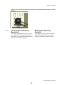
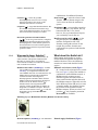
1.1.1.
Where are the Controls?
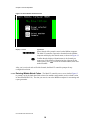
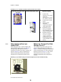
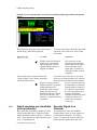
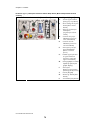
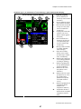
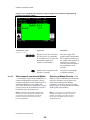
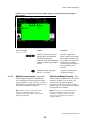
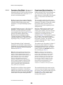
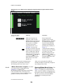
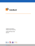
The essential controls for normal operation are located on the front control panel (Figure 1).
Additional controls and connections are located elsewhere on the machine, as described here.
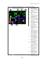
Figure 1: Locations of Controls
Front Left View
Rear View
Legend
A.
B.
C.
D.
E.
.
1.1.2.
Microprocessor control
box (68036F_B shown)
Control panel
Manual supply flush
button
Hydraulic pressure gauge
for loading door
Air pressure gauge for tilt
system (behind lower rear
panel)
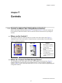
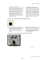
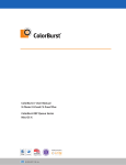
Where do I Connect the Data Storage Device?
The microprocessor box in the upper rear corner of the machine left side panel (see Figure 1)
contains a DIN-type connection for serial communications. Use this connection, labelled as
shown in Figure 2, with a serial data transfer device to save or restore machine programming and
configuration memory.
PELLERIN MILNOR CORPORATION
7
Chapter 1. Controls
Figure 2: Serial Connection for Data Transfer
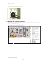
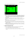
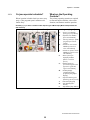
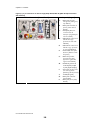
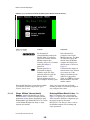
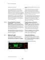
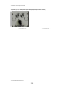
1.1.3.
What are the Operating Controls?
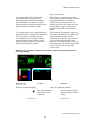
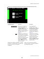
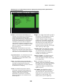
The primary operating controls are required to start and stop the machine, select wash formulas,
and monitor machine operation.
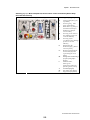
Figure 3: Mark VI Staph Guard Soil Side Controls
Control Panel
Legend
A.
B.
C.
D.
E.
F.
G.
.
H.
I.
J.
K.
L.
PELLERIN MILNOR CORPORATION
8
Emergency stop button
Door unlock button
Jog/Autospot selector
switch
Control on clean side
indicator
Control on soil side
indicator
Master switch for power
Operator signal and
signal cancel button
Liquid crystal graphic
display
Run/Program keyswitch
Keypad
Start button
Stop button
Chapter 1. Controls
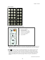
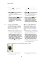
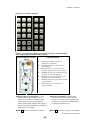
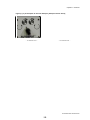
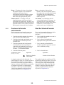
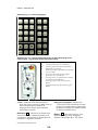
Figure 4: Keypad
Figure 5: Typical Staph Guard Clean Side Controls
Control Panel
Legend
A.
B.
C.
D.
E.
F.
G.
Emergency stop button
Door unlock button
Jog/Autospot selector switch
Control on clean side indicator
Control on soil side indicator
Control transfer button
Jog/spot button
.
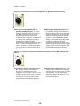
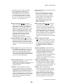
Emergency stop button—disables the 3-wire circuit. This switch locks in when pressed, so you
must turn it a quarter turn to allow it to return to the normal position to allow the machine to
run.
Notice 1 : Press the emergency stop button immediately in any emergency situation. This
disables the 3-wire circuit, which stops all machine operation and causes the drain to open.
• When you reset this button, you have the option of cancelling or resuming the interrupted
formula. The formula resumes where it was interrupted or at the beginning of the previous
bath step, depending on the operation in progress when the emergency stop button was
pressed.
PELLERIN MILNOR CORPORATION
9
Chapter 1. Controls
Master power switch (m / M)—removes power from the control system. If you turn the master
switch off (m) while a formula is running, the immediate result is similar to pressing the
emergency stop button: the machine stops and the drain opens. Unlike the emergency stop
button, resumed formulas start at the beginning of the step in which power was lost, but
chemicals are not injected in the resumed step.
Operator signal cancel button (A)—cancels the operator signal. Press this button to silence the
buzzer and turn off the operator signal light (see below), or to allow injection of a chemical
programmed to require a signal before injection.
Operator signal light—indicates that the machine has encountered an error or that the operator
must perform some action, such as pressing the start button or unloading the machine. The
operator signal circuit includes a buzzer behind the control panel, and may include an optional
beacon light mounted separately from the control panel.
Liquid crystal graphic display—displays information and help about the machine. The
information on the display changes according to the status of the machine and the function
selected by the operator.
Keypad—allows the operator to communicate with the machine control system. The keypad is
divided into three areas: alphanumeric buttons, general buttons, and function-specific buttons.
Each button may perform more than one function, based on the current machine status. Some
buttons are also used in combinations for additional functions.
Start button (1)—starts the selected wash formula. The start button energizes the 3-wire circuit
to allow the machine to operate.
Stop button (0)—stops machine operation. Like the emergency stop button, the stop button
disables the 3-wire circuit; however, the stop button doesn't require you to manually reset it
after use.
Run/Program keyswitch (R/P)—in the Program position, allows changes to machine
configuration and wash formulas, among other actions. In the normal Run position, formulas
and configuration are protected and formulas can be run.
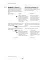
1.1.4.
What does this Switch do?
Other buttons and switches are used to control additional standard and optional machine
functions. These miscellaneous controls are located and described in this section.
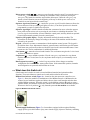
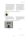
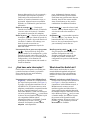
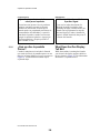
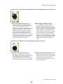
Mildata/Local selector switch (Figure 6)—located on the microprocessor control box (see
Figure 1), allows the machine to communicate with a Mildata network. A Mildata network
connects several machines together and allows them to share wash formulas and other data
with the Mildata computer. When this switch is in the Mildata position (-) and you enter a
formula number, the machine requests the contents of the formula from the Mildata computer.
When set to the Local position (_), only formulas present in the machine are available.
Figure 6: Mildata/Local Selector switch
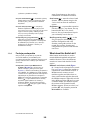
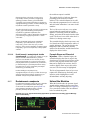
Manual supply flush button (Figure 7)—On machines equipped with an optional flushing
supply injector, press this button to spray water into the supply injector to flush any remaining
PELLERIN MILNOR CORPORATION
10
Chapter 1. Controls
chemicals into the cylinder. If you manually add supplies during a wash formula, press this
button to flush any remaining undiluted chemicals out of the supply chute. If the machine is
not equipped with the optional supply injector, press this button to flush the liquid chemical
inlets with fresh water.
Figure 7: Manual Supply Flush button
Autospot selector switch (Figure 8)—Some divided-cylinder machines are equipped with the
Autospot feature to aid in loading and unloading. This optional feature optimally positions the
basket for access to the selected pocket.
Figure 8: Autospot selector switch
— End of BICWCO02 —
PELLERIN MILNOR CORPORATION
11
Chapter 2. Normal Operation
Chapter 2
Normal Operation
BICWCO03 (Published) Book specs- Dates: 20070515 / 20070515 / 20070515 Lang: ENG01 Applic: CWS
2.1. Operating Instructions for Plant Personnel
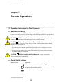
2.1.1.
Start Here for Safety
This document is meant to remind you, the person operating this washer extractor, of what is
required to operate this machine. Do not attempt to operate this machine before an experienced,
trained operator explains the details to you.
DANGER 2 : Multiple Hazards—Careless operator actions can kill or injure personnel,
damage or destroy the machine, damage property, and/or void the warranty.
DANGER 3 : Electrocution and Electrical Burn Hazards—Contact with electric power
can kill or seriously injure you. Electric power is present inside the cabinetry unless the main
machine power disconnect is off.
• Do not unlock or open electric box doors.
• Know the location of the main machine disconnect and use it in an emergency to remove
all electric power from the machine.
• Do not service the machine unless qualified and authorized. You must clearly understand
the hazards and how to avoid them.
CAUTION 4 : Collision, Crushing and Pinch Hazards—Contact with moving
components normally isolated by guards, covers, and panels, can entangle and crush your limbs.
These components move automatically.
2.1.2.
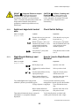
Check Switch Settings
Display or Action
Explanation
R
Check that the run/program keyswitch is at R.
All emergency stop buttons must be unlatched and in the ready
position to allow machine operation.
m/M
Check that the master switch is at M.
PELLERIN MILNOR CORPORATION
12
Chapter 2. Normal Operation
2.1.3.
How do I Load a StaphGuard® Machine?
Display or Action
Explanation
d+l
!
l+1
Open the outer door.
Select a pocket to load.
Align the selected pocket with the outer door.
Open the inner door of the first pocket to load.
Use the procedure defined by facility management to put the goods in the machine.
Close and latch the inner door.
Open the inner door of the first pocket to load.
Verify that all pockets are loaded with similar goods to about the same weight.
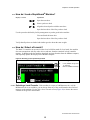
2.1.4.
How do I Select a Formula?
The Mark VI controller can operate in either local or Mildata mode. In local mode, the machine
does not communicate with any other devices and runs formulas contained in local controller
memory. In Mildata mode the machine downloads and runs formulas from the Mildata computer,
and frequently updates the display on the Mildata computer.
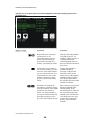
Figure 9: Selecting a Local or Remote Formula
Select Program Displays
Legend
A.
B.
Local (Mildata not present
or enabled)
Remote (Mildata enabled)
.
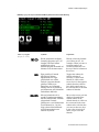
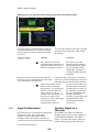
2.1.4.1.
Selecting a Local Formula—If the machine is not part of a Mildata network, or if the
Mildata network is not available, you can choose from any of the wash formulas stored in local
memory on the machine. Use the Select Local Formula screen (Figure 10) to choose the correct
formula for the goods in the machine.
PELLERIN MILNOR CORPORATION
13
Chapter 2. Normal Operation
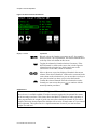
Figure 10: Select Local Formula Screen
Display or Action
Explanation
07
k
&/^
u
Directly selects the formula you want to run (07, for example).
When you enter a two-digit number, the selected formula moves
to the top of the left column on this screen.
Toggles the column for formula selection if necessary. If the
desired formula is visible on the screen, but is in the opposite
column from the selection box, this keystroke moves the
selection box to the other column of formulas.
Move to the next or previous displayed formula in the current
column. If the desired formula is visible on the screen and in the
same column as the selection box, you can use these two keys to
move the selection box down or up to select the formula.
Confirm the selected formula. Place the selection box on the
formula you want to run, then press u to continue with the
normal operation procedures.
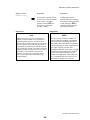
Supplement 1
About Load Weight and Metered Water
Metered water is available on Mark VI washer-extractors equipped with optional flow meters
on the incoming water lines. This feature allows the Mark VI controller to admit a quantity of
water proportional to the weight of goods you enter after selecting the formula. If you enter a
weight of 200 units when prompted, the machine will use twice as much water as if you entered
100 weight units. This option can save a significant amount of water if you enter accurate
weights for each load.
PELLERIN MILNOR CORPORATION
14
Chapter 2. Normal Operation
Figure 11: Entering Load Weight for Metered Water
Display or Action
Explanation
449
u
2.1.4.2.
Enter the weight of the goods loaded in the machine. The
machine controller uses the weight to determine how much water
is needed to wash the goods according to the programmed wash
formula.
Accept the entered goods weight and continue.
Selecting a Mildata Formula—If the machine is part of a Mildata network and the
network is available, you can choose any wash formula stored on the Mildata computer. Use the
Select Remote Formula screen (Figure 12) to choose the best formula for the goods in the
machine.
Note 1: You can store up to 1000 different wash formulas on the Mildata computer. All of these formulas
are available to all washer-extractors that are part of the Mildata network and have compatible hardware.
PELLERIN MILNOR CORPORATION
15
Chapter 2. Normal Operation
Figure 12: Select Remote Formula Screen
Display or Action
Explanation
0928
Select formula 928 (example) stored on the Mildata computer.
The Mark VI controller requests the formula from the Mildata
computer and displays the formula name, as shown in Figure 12.
u
Confirm that the displayed formula name is the formula you
want to run. If the displayed formula isn't the right one for the
loaded goods, press c to clear the formula number, then enter
another number.
After you've retrieved and verified the formula, the Mark VI controller prompts for any
configured batch data.
2.1.4.3.
Entering Mildata Batch Codes—The Mark VI controller uses a screen similar Figure 13
to prompt you for the batch data fields selected in machine configuration (see the related section
in document BICWCC01). The data you enter is sent to the Mildata computer for accounting and
report generation.
PELLERIN MILNOR CORPORATION
16
Chapter 2. Normal Operation
Figure 13: Batch Data for Remote Formula Operation
Weight—the weight of the batch of goods in the machine. This information is usually used along
with other batch data to calculate customer charges or employee productivity. In machines
equiped with optional flow meters and configured for metered water, the weight value is also
used to determine how much water is required to process the batch. The weight value can be
up to three digits.
Customer Code—the identifying code for the customer. This information can help you
determine how much work each customer is submitting. Ten digits are available for customer
code.
Employee Number—the identifying code for the employee responsible for this batch. The
employee number may be up to five digits long.
Pieces—the number of pieces in the machine. This value sometimes replaces the weight value,
especially when charges are made by the piece rather than by weight. Four digits are available
for the number of pieces.
Lot Number—the identifying code for several related batches or customers. At your discretion,
the value entered here might represent a particular route number common to several accounts.
A lot number can be up to 10 digits long.
2.1.5.
Start the Selected Formula
Be sure you've completed these steps before you go any further in the operating procedure.
1. You've loaded the machine at or near its rated weight capacity.
2. You've selected a formula that's appropriate for the goods in the machine.
3. You've entered any batch data the machine controller requires for metered water or Mildata
reporting.
PELLERIN MILNOR CORPORATION
17
Chapter 2. Normal Operation
4. You've closed the door.
Display or Action
Explanation
1
Start the selected formula.
The machine begins the wash formula. The basket begins turning and water valves open. When a
safe level is achieved, the steam valve may open to begin heating the bath. Operation from this
point to the end of the formula is completely automatic unless a signal is programmed with a
chemical injection (see Supplement 2).
Supplement 2
Chemical Injections with the Operator Signal
If you need to adjust the amount of a chemical injection from load to load depending on highly
variable factors, the formula can be programmed to stop the timer and signal you when a
chemical is required. Add the chemical, then press A to resume the formula.
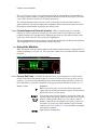
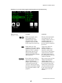
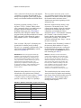
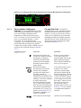
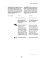
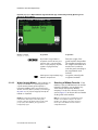
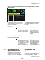
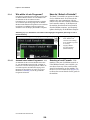
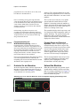
2.1.6.
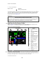
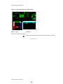
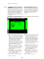
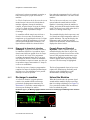
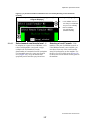
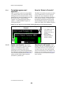
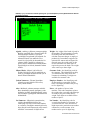
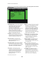
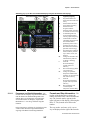
What Does the Run Display Tell Me?
While the machine is running the formula you selected, the display appears similar to the one
shown in Figure 14. The information shown here is explained below.
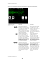
Figure 14: How to Read the Run Display
Typical Display
Legend
A.
B.
C.
D.
E.
F.
G.
H.
I.
J.
K.
.
L.
M.
2.1.6.1.
Formula number and
name
Step number and name
Total time for formula and
current step
Basket rotation graphic
and speed
Remaining time for entire
formula and current step
Machine status message
Formula steps: number,
name, and duration
Indicator for filling or
draining
Graphic bath level
indicator
Water valves indicators
Indicator for optional
steam and cooldown
valves
Graphic bath temperature
indicator
Bath temperature and
level data
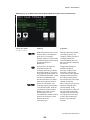
Formula and Step Information—The top line of the display always shows the number
and name of the current formula and step. The formula number appears in the upper left corner of
the display, following the letter “F.”The formula name follows the number.
PELLERIN MILNOR CORPORATION
18
Chapter 2. Normal Operation
The step number and name of the current step are displayed to the right of the formula
information. The Mark VI controller updates the formula number and name when a formula starts
and at the beginning of each subsequent step.
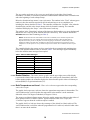
Below the formula and step names is time information. The numbers in the “Total” column (green
numbers) show the total time required for the formula and step to run to completion, not
including the factors described in Note 2. The controller calculates the “Formula” value when the
formula begins, and this value doesn't change while the formula is running. The controller
calculates and displays the “Step x” value at the start of each step.
The numbers in the “Remaining” column of the time area (black numbers on a green background)
indicate the time remaining in the formula and in the current step. These numbers indicate the
minimum amount of time remaining (see Note 2).
Note 2: The duration of some wash formula events can't be estimated, so the controller stops the timer
until a requirement is met. For example, the time required for the machine to fill to the desired level
depends on the water pressure to the plant, the size of the piping to the machine, and how many other
machines are filling at the same time. In addition to the time required to fill, the time required to achieve
temperature or for an operator to verify a chemical injection are variable. Error conditions can also stop the
timer.
The controller displays the current machine status below the step number and remaining time.
Some of the possible machine states are listed in Table 1. Error messages appear immediately
below the machine status message when required.
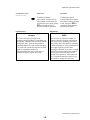
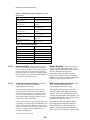
Table 1: Machine Status Messages
2.1.6.2.
Idle
Coasting
1-way Wash
Waiting to Discharge
2-way Wash
Waiting for Load
Soak
Power-up Delay
Pre+Final Extract
Draining to Sewer
Intermediate Extract
Draining to Reuse
Final Extract
Timer Stopped
Double Extract
Please Wait xx Seconds
Basket Rotation—The basket rotation graphic near the upper right corner of the display
represents the relative basket speeds in wash, drain, and extract speeds. Immediately below the
basket rotation graphic, the controller displays the desired basket speed in either revolutions per
minute (RPMs) or in gravitational units (G's).
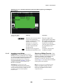
2.1.6.3.
Bath Temperature and Level—Water valve indicators appear when the corresponding
water valve is open.
The graphic bath temperature indicator shows the approximate temperature in the machine. The
vertical indicator bar is solid red when the temperature in the machine is at the maximum
allowable value of 205 degrees Fahrenheit (95 degrees Celsius).
The steam or cooldown indicator appears below the graphic temperature indicator when either of
these optional features is enabled. “Steam” appears when the steam valve is open, and
“Cooldown” appears when the cooldown output is enabled.
The graphic bath level indicator shows the percentage of the desired level that's achieved. The
vertical indicator bar is solid blue when the programmed level is achieved, and solid white when
there is no water in the machine.
PELLERIN MILNOR CORPORATION
19
Chapter 2. Normal Operation
The level direction indicator arrow points upward when the actual bath level in the machine is
increasing (when the machine is filling), and points downward when the drain opens. The arrow
is not visible when level is achieved, or during extract steps.
The controller displays bath temperature and level data between the temperature and level
graphic indicators. The top line displays the temperature and level that are currently achieved in
the machine, and the bottom line displays the desired values.
2.1.6.4.
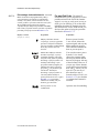
Formula Steps and Chemical Injection—When a formula begins, the controller
displays the first six steps in the formula steps list in the lower left area of the screen. If the
program contains more steps than can be displayed at one time, the list scrolls to display more
steps as the earlier ones end. The current step is highlighted.
The list of programmed chemical injections replaces the formula steps list during each injection,
with a highlight box on the chemical that's currently injecting.
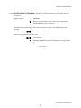
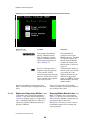
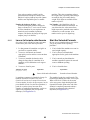
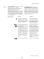
2.1.7.
Unload the Machine
When the formula ends, the operator signal sounds and the machine displays a message that it is
waiting to discharge (see Figure 15). Use a procedure similar to the one outlined below to unload
the goods.
Figure 15: Typical Message when Formula Ends
2.1.7.1.
For any End Code—The Mark VI controller allows you to program one of four possible
actions for the end of the formula: stopped, reversing at wash speed, turning at drain speed, or
tumbling. You use the same unloading procedure for formulas using the first three actions. For
the fourth action, you also have the option of using the procedure described in Section 2.1.7.2.
Display or Action
Explanation
l
Remove power from the 3-wire circuit, silence the operator
signal, and stop any basket motion in progress. This button also
unlocks the door so you can open it.
0/A/
You can also remove power from the 3-wire circuit, silence the
operator signal, and stop any basket motion that was in progress
with any of these buttons. However, if you use any of these
buttons, you'll still need to unlock the door with l before you
can open it. If you use any of these buttons to stop a formula
with end code 3 (see Section 2.1.7.2), the formula is terminated
and cannot be resumed.
l+d
Open the door for unloading.
PELLERIN MILNOR CORPORATION
20
Chapter 2. Normal Operation
2.1.7.2.
For End Code 3 (Tumbling)—End code 3 (Tumbling) allows you to open the door and
remove some of the goods, then close the door and resume tumbling to loosen more goods from
the basket.
Display or Action
Explanation
l
Remove power from the 3-wire circuit, silence the operator
signal, and stop any basket motion in progress. This button also
unlocks the door so you can open it.
When the basket stops turning, open the door and remove some or all of the goods from the
machine.
l+d
Open the door for unloading.
Remove any desired portion of the load.
D+l
1
Close the door.
Resumes the tumbling action without the operator signal.
Tumbling continues for another two minutes, or until you press
l.
— End of BICWCO03 —
PELLERIN MILNOR CORPORATION
21
Chapter 3. Signals and Errors
Chapter 3
Signals and Errors
BICWCT04 (Published) Book specs- Dates: 20070515 / 20070515 / 20070515 Lang: ENG01 Applic: CWS
3.1. Operator Intervention
Once a formula starts, the machine usually runs automatically. The machine will sound the signal
if an operator needs to make a decision or do something manually. The most common reasons
you'll need to attend to the machine are errors, and to manually add chemicals in some cases.
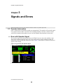
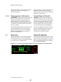
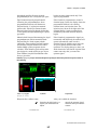
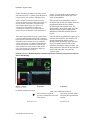
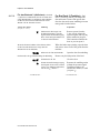
3.1.1.
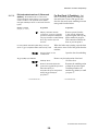
Error with Operator Signal
The operator signal will sound and the beacon will flash if an error causes the machine to stop.
These errors usually disable the three-wire circuit, and include a tripped vibration switch or a
malfunction of the inverter that controls the motor. Figure 16 shows how a vibration switch error
appears on the display.
Figure 16: Typical Error with Operator Signal
PELLERIN MILNOR CORPORATION
22
Chapter 3. Signals and Errors
To resume the formula, silence the signal and correct the cause of the error. Then, restart the
formula.
Display or Action
Explanation
A
The Cancel key on the keypad stops the machine, silences the
operator signal buzzer, and turns off the signal light. You'll have
to restart the formula from the beginning.
Correct the cause of the error. If you don't know how to fix the problem, have someone check the
reference manual for the machine.
1
3.1.2.
If you've corrected the error, the Start button resumes the
formula where it stopped. If the vibration switch caused the
error, the machine goes through a distribution sequence to spread
the goods around the basket, then resumes the interrupted extract
step.
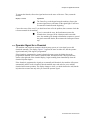
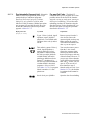
Operator Signal for a Chemical
This machine can control an automatic chemical pump system, or it can signal you to add
chemicals manually. The display (Figure 17) appears the same in either case, but the operator
signal sounds only if the signal is programmed.
If the formula is programmed to control a chemical pump system, the display shows the
programmed chemical valve number, chemical name, and injection time. The injection time,
shown at the right end of the chemical display, begins counting down immediately when the
chemical injection begins.
If the formula is programmed to signal you to manually add chemicals, the machine will operate
automatically until it needs a chemical, then the machine stops and waits for you to add the
chemical and resume operation. The display changes to show you which chemical to add, but the
injection time counter runs only after you cancel the operator signal.
PELLERIN MILNOR CORPORATION
23
Chapter 3. Signals and Errors
Figure 17: Chemical Injection View on Run Display
Display or Action
Explanation
After you've added the chemical,
A
cancels the operator signal and starts the injection time counter.
— End of BICWCT04 —
PELLERIN MILNOR CORPORATION
24
eský
25
2
Published Manual Number: MQCWSO01CS
•
•
•
•
•
•
•
Specified Date: 20070515
As-of Date: 20070515
Access Date: 20080521
Depth: Detail
Custom: n/a
Applicability: CWS
Language Code: CZE01, Purpose: publication, Format: 2colA
Příručka operátora [Operator
Guide]—
StaphGuard® Pračka s
kontrolérem Mark VI
[StaphGuard® Washer-extractor
with Mark VI Controller]
POZOR: The information contained in this manual has been provided by
Pellerin Milnor Corporation in the English version only. Milnor has tried to
obtain a quality translation, but makes no claims, promises, or guarantees
about the accuracy, completeness, or adequacy of the information contained
in the non-English version.
Moreover, Milnor has made no attempt to verify the information contained in
the non-English version, as it was completely done by a third party.
Therefore, Milnor expressly denies liability for errors in substance or form
and undertakes no responsibiity for the reliance on, or consequences of,
using the information in the non-English version.
Under no circumstances shall Milnor or its agents or officers be liable
for any direct, indirect, incidental, punitive, or consequential damages
that may result in any way from the use or inability to use, or reliance
on, the non-English version of this manual, or that result from
mistakes, omissions, or errors in translation.
Čti bezpečnostní manuál
PELLERIN MILNOR CORPORATION
27
POST OFFICE BOX 400, KENNER, LOUISIANA 70063 - 0400, U.S.A.
Aplikovatelné Milnor® Produkty podle čísla modelu: [Applicable
Milnor® products by model number:]
42044SP2
42044SP3
60044SP2
60044SP3
28
72044SP2
Tabulka obsahů
Tabulka obsahů
[English table of contents follows]
Sekce
Obrázky, tabulky a přílohy
Kapitola 1. Ovladače
1.1. Ovladače na Značka VI Nevyklápět pračce - ždímačce
(Dokument BICWCO02)
1.1.1. Kde jsou ovladače?
Obrázek 1: Umístění ovládacích prvků
[Locations of Controls]
Obrázek 2: Řadové spoje pro transfer dat
[Serial Connection for Data Transfer]
Obrázek 3: Boční ovladače hlídání
ušpinění typu VI Mark Staph [Mark
VI Staph Guard Soil Side Controls]
Obrázek 4: Klávesnice [Keypad]
Obrázek 5: Typické boční ovladače
hlídačů Staph [Typical Staph Guard
Clean Side Controls]
Obrázek 6: Mildata/místní volící spínač
[Mildata/Local Selector switch]
Obrázek 7: Tlačítko ručního napouštění
[Manual Supply Flush button]
Obrázek 8: Volící spínač Autospotu
[Autospot selector switch]
1.1.2. Kde napojím zařízení pro uložení dat?
1.1.3. Co jsou operační ovladače?
1.1.4. Co tento spínač dělá?
Kapitola 2. Normální operace
2.1. Pracovní instrukce pro obslužný personál
(Dokument
BICWCO03)
2.1.1.
2.1.2.
2.1.3.
2.1.4.
Zde startuj kvůli bezpečnosti
Nastavení kontrolního spínače
Jak mohu naložit StaphGuard® stroj?
Jak mám zvolit program?
Obrázek 9: Volí místní nebo externí
programy [Selecting a Local or
Remote Formula]
Obrázek 10: Zvol místní program
obrazovka [Select Local Formula
Screen]
Příloha 1: O váze nákladu a Odměřená
voda
Obrázek 11: Zapisování váhy nákladu pro
měřenou vodu [Entering Load Weight
for Metered Water]
Obrázek 12: Zvol externí program
Obrazovka [Select Remote Formula
Screen]
2.1.4.1. Volí místní program
2.1.4.2. Volba programu Mildata
PELLERIN MILNOR CORPORATION
29
Tabulka obsahů
Sekce
Obrázky, tabulky a přílohy
2.1.4.3. Zapisování Kódy dávky Mildata
2.1.5. Startuj zvolený program
2.1.6. Co mi displej Běh oznamuje?
2.1.6.1. Informace o programu a kroku
2.1.6.2. Rotace koše
2.1.6.3. Teplota dávky a hladina
2.1.6.4. Kroky programu a vstřik pracích prostředků
2.1.7. Vylož stroj
Obrázek 13: Data dávky pro funkci
externího programu [Batch Data for
Remote Formula Operation]
Příloha 2: Vstříknutí chemikálií (pracích
prostředků) v návaznosti na signál
operátora.
Obrázek 14: Jak číst displej Běh [How to
Read the Run Display]
Tabulka 1: Zpráva o stavu stroje
Obrázek 15: Typická zpráva když program
skončí [Typical Message when
Formula Ends]
2.1.7.1. Pro jakoukoliv Koncový kód
2.1.7.2. pro koncový kód 3 (Máchání)
Kapitola 3. Signály a chyby
3.1. Zásah operátora (Dokument BICWCT04)
3.1.1. Chyba ve spojitosti se signálem operátora
3.1.2. Signál operátora pro chemikálie (prací prostředky)
PELLERIN MILNOR CORPORATION
30
Obrázek 16: Typická chyba v souvislosti
se signálem operátora [Typical Error
with Operator Signal]
Obrázek 17: Pohled na vstřik pracích
prostředků na běžícím displeji
[Chemical Injection View on Run
Display]
Table of Contents
Table of Contents
Sections
Figures, Tables, and Supplements
Chapter 1. Controls
1.1. Controls on Mark VI Non-Tilting Washer-extractors
(Document BICWCO02)
1.1.1. Where are the Controls?
1.1.2. Where do I Connect the Data Storage Device?
1.1.3. What are the Operating Controls?
1.1.4. What does this Switch do?
Figure 1: Umístění ovládacích prvků
[Locations of Controls]
Figure 2: Řadové spoje pro transfer dat
[Serial Connection for Data Transfer]
Figure 3: Boční ovladače hlídání ušpinění
typu VI Mark Staph [Mark VI Staph
Guard Soil Side Controls]
Figure 4: Klávesnice [Keypad]
Figure 5: Typické boční ovladače hlídačů
Staph [Typical Staph Guard Clean
Side Controls]
Figure 6: Mildata/místní volící spínač
[Mildata/Local Selector switch]
Figure 7: Tlačítko ručního napouštění
[Manual Supply Flush button]
Figure 8: Volící spínač Autospotu
[Autospot selector switch]
Chapter 2. Normal Operation
2.1. Operating Instructions for Plant Personnel
(Document
BICWCO03)
2.1.1.
2.1.2.
2.1.3.
2.1.4.
Start Here for Safety
Check Switch Settings
How do I Load a StaphGuard® Machine?
How do I Select a Formula?
Figure 9: Volí místní nebo externí
programy [Selecting a Local or
Remote Formula]
Figure 10: Zvol místní program obrazovka
[Select Local Formula Screen]
Supplement 1: About Load Weight and
Metered Water
Figure 11: Zapisování váhy nákladu pro
měřenou vodu [Entering Load Weight
for Metered Water]
Figure 12: Zvol externí program
Obrazovka [Select Remote Formula
Screen]
2.1.4.1. Selecting a Local Formula
2.1.4.2. Selecting a Mildata Formula
PELLERIN MILNOR CORPORATION
31
Table of Contents
Sections
Figures, Tables, and Supplements
2.1.4.3. Entering Mildata Batch Codes
2.1.5. Start the Selected Formula
2.1.6. What Does the Run Display Tell Me?
2.1.6.1. Formula and Step Information
2.1.6.2. Basket Rotation
2.1.6.3. Bath Temperature and Level
2.1.6.4. Formula Steps and Chemical Injection
2.1.7. Unload the Machine
Figure 13: Data dávky pro funkci
externího programu [Batch Data for
Remote Formula Operation]
Supplement 2: Chemical Injections with
the Operator Signal
Figure 14: Jak číst displej Běh [How to
Read the Run Display]
Table 1: Machine Status Messages
Figure 15: Typická zpráva když program
skončí [Typical Message when
Formula Ends]
2.1.7.1. For any End Code
2.1.7.2. For End Code 3 (Tumbling)
Chapter 3. Signals and Errors
3.1. Operator Intervention (Document BICWCT04)
3.1.1. Error with Operator Signal
Figure 16: Typická chyba v souvislosti se
signálem operátora [Typical Error
with Operator Signal]
Figure 17: Pohled na vstřik pracích
prostředků na běžícím displeji
[Chemical Injection View on Run
Display]
3.1.2. Operator Signal for a Chemical
PELLERIN MILNOR CORPORATION
32
Kapitola 1. Ovladače
Kapitola 1
Chapter 1
Ovladače
Controls
BICWCO02 (Published) Book specs- Dates: 20070515 / 20070515 / 20080521 Lang: CZE01 Applic: CWS
1.1.
Ovladače na Značka VI
Nevyklápět pračce - ždímačce
Controls on Mark VI NonTilting Washer-extractors
Kde jsou ovladače?
Where are the Controls?
Viz další části tohoto dokumentu (Sekce 1.1.2 a
to prostřednictvím Sekce 1.1.4) pro lokaci a
základní funkce jednotlivých ovladačů.
Nepoužívej tento dokument jako instrukce pro
ovládání stroje.
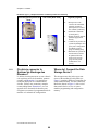
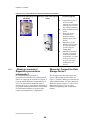
1.1.1.
Hlavní ovladače pro normální ovládání jsou na
předním ovládacím panelu (Obrázek 1).
Přídavné ovladače a spojení jsou umístěny
kdekoli na stroji jak zde popsáno.
Refer to other parts of this document
(Section 1.1.2 through Section 1.1.4) for the
location and basic function of individual
controls. Don't use this document as
instructions for operating the machine.
The essential controls for normal operation
are located on the front control panel (Figure
1). Additional controls and connections are
located elsewhere on the machine, as
described here.
PELLERIN MILNOR CORPORATION
33
Kapitola 1. Ovladače
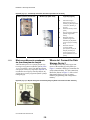
Obrázek [Figure] 1: Umístění ovládacích prvků [Locations of Controls]
Pohled zleva zepředu [Front
Left View]
Pohled zezadu [Rear View]
Legenda [Legend]
A.
B.
C.
.
D.
E.
1.1.2.
Kde napojím zařízení pro
uložení dat?
Skříň mikroprocesoru v horním zadním rohu
stroje bočního levého panelu (viz Obrázek 1)
obsahuje spoje DIN-typu pro řadovou
komunikaci. Používej tyto spoje, označené jak
ukazuje Obrázek 2, spolu se zařízením pro
řadový transfer dat k uložení nebo obnově
programovací a konfigurační paměti stroje.
Ovládací skříň
mikroprocesoru (ukazuje
68036F_B)
[Microprocessor control
box (68036F_B shown)]
Ovládací panel [Control
panel]
Tlačítko ručního
napouštění
(vyplachování) [Manual
supply flush button]
Hydraulický tlakový
přístroj pro nakládací
dveře [Hydraulic pressure
gauge for loading door]
Pneumatický tlakový
přístroj pro vyklápěcí
systém (za spodním
zadním panelem) [Air
pressure gauge for tilt
system (behind lower rear
panel)]
Where do I Connect the Data
Storage Device?
The microprocessor box in the upper rear
corner of the machine left side panel (see
Figure 1) contains a DIN-type connection for
serial communications. Use this connection,
labelled as shown in Figure 2, with a serial
data transfer device to save or restore
machine programming and configuration
memory.
Obrázek [Figure] 2: Řadové spoje pro transfer dat [Serial Connection for Data Transfer]
PELLERIN MILNOR CORPORATION
34
Kapitola 1. Ovladače
Co jsou operační ovladače?
1.1.3.
Hlavní operační ovladače slouží pro start a stop
stroje, výběr programů praní a monitorování
funkce stroje.
What are the Operating
Controls?
The primary operating controls are required
to start and stop the machine, select wash
formulas, and monitor machine operation.
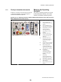
Obrázek [Figure] 3: Boční ovladače hlídání ušpinění typu VI Mark Staph [Mark VI Staph Guard Soil
Side Controls]
Ovládací panel [Control Panel]
Legenda [Legend]
A.
B.
C.
D.
E.
.
F.
G.
H.
I.
J.
K.
L.
Nouzový stop tlačítko
[Emergency stop button]
Odjištění dveří tlačítko
[Door unlock button]
Volič Jog/Autospot spínač
[Jog/Autospot selector
switch]
Ovladač na čisté straně
indikátor [Control on
clean side indicator]
Ovladač na špinavé straně
indikátor [Control on soil
side indicator]
Hlavní spínač pro
napájení proudem
[Master switch for
power]
tlačítka Signál pro
operátora a Signál zrušit
[Operator signal and
signal cancel button]
Grafický displej
z tekutých krystalů
[Liquid crystal graphic
display]
Přepínač Běh/Program
[Run/Program keyswitch]
klávesnice [Keypad]
Start tlačítko [Start
button]
Stop tlačítko [Stop button]
PELLERIN MILNOR CORPORATION
35
Kapitola 1. Ovladače
Obrázek [Figure] 4: Klávesnice [Keypad]
Obrázek [Figure] 5: Typické boční ovladače hlídačů Staph [Typical Staph Guard
Clean Side Controls]
Ovládací panel [Control
Panel]
Legenda [Legend]
A.
B.
C.
D.
E.
F.
G.
Nouzový stop tlačítko [Emergency stop
button]
Odjištění dveří tlačítko [Door unlock
button]
Jog/Autospot volič spínač [Jog/Autospot
selector switch]
Ovladač na čisté straně indikátor [Control
on clean side indicator]
Ovladač na špinavé straně indikátor
[Control on soil side indicator]
Řízený transfer tlačítko [Control transfer
button]
Jog/spot tlačítko [Jog/spot button]
.
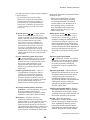
Tlačítko nouzového zastavení—Vyřazuje 3fázový obvod. Tento spínač blokuje, když je
stisknut, a tak jej musíte otočit o čtvrtinu,
aby se vrátil do normální polohy aby stroj
běžel.
Emergency stop button—disables the 3wire circuit. This switch locks in when
pressed, so you must turn it a quarter turn
to allow it to return to the normal position
to allow the machine to run.
Oznámení 1 : Stiskni ihned Nouzový stop
tlačítko při jakékoliv nouzové situaci. To vyřadí
3-fázový obvod, který zastaví všechny operace
Notice 1 : Press the emergency stop
button immediately in any emergency
situation. This disables the 3-wire circuit,
PELLERIN MILNOR CORPORATION
36
Kapitola 1. Ovladače
stroje a otevření vypouštění.
• Když znovunastavíte toto tlačítko, máte
možnost volby zrušit nebo pokračovat
v přerušeném programu. Program se
obnoví kde byl přerušen, nebo na
začátku předchozího kroku dávky, a to
v závislosti na operaci, která běžela když
tlačítko Nouzový stop bylo stlačeno.
which stops all machine operation and causes
the drain to open.
• When you reset this button, you have
the option of cancelling or resuming
the interrupted formula. The formula
resumes where it was interrupted or at
the beginning of the previous bath
step, depending on the operation in
progress when the emergency stop
button was pressed.
Hlavní spínač napájení (m / M)—Vypne
proud v ovládacím systému. Když vypnete
Hlavní spínač z (m) při běhu programu, tak
okamžitý výsledek je podobný jako když
stisknete tlačítko Nouzový stop: Stroj zastaví
a otevře se vypouštění. Na rozdíl od tlačítka
Nouzový stop, obnovené programy nastartují
na počátku kroku, kdy proud byl přerušen,
ale chemikálie (prací prostředky) nejsou
v obnoveném kroku vstříknuty.
Master power switch (m / M)—removes
power from the control system. If you
turn the master switch off (m) while a
formula is running, the immediate result
is similar to pressing the emergency stop
button: the machine stops and the drain
opens. Unlike the emergency stop button,
resumed formulas start at the beginning of
the step in which power was lost, but
chemicals are not injected in the resumed
step.
Rušící tlačítko signálu operátora (A)—Ruší
Signál operátora. Stiskni toto tlačítko pro
umlčení bzučáku a vypni Signál operátora
světlo (viz dole), nebo povol vstřik
chemikálií (pracích prostředků)
naprogramovaných na signál před vstřikem.
Operator signal cancel button (A)—
cancels the operator signal. Press this
button to silence the buzzer and turn off
the operator signal light (see below), or
to allow injection of a chemical
programmed to require a signal before
injection.
Světlo signálu operátora—Indikuje, že stroj
provedl chybu nebo že operátor musí provést
nějakou akci, jako je stisk tlačítka Start nebo
vyprázdnění stroje. Obvod Signál operátora
obsahuje bzučák za ovládacím panelem a
může mít výstražné světlo (na objednávku)
namontované separátně od ovládacího
panelu.
Operator signal light—indicates that the
machine has encountered an error or that
the operator must perform some action,
such as pressing the start button or
unloading the machine. The operator
signal circuit includes a buzzer behind the
control panel, and may include an
optional beacon light mounted separately
from the control panel.
Grafický displej z tekutých krystalů—
Zobrazuje informace a nápovědy ohledně
stroje. Informace na displeji se mění podle
stavu stroje a funkcí zvolených operátorem.
Liquid crystal graphic display—displays
information and help about the machine.
The information on the display changes
according to the status of the machine and
the function selected by the operator.
Klávesnice—Dovoluje operátorovi
komunikovat s řídícím systémem stroje.
Klávesnice je rozdělena na tři oblasti:
alfanumerická tlačítka, hlavní tlačítka a
specifická tlačítka funkcí. Každé tlačítko
může ovládat více než jednu funkci na
základě běžícího stavu stroje. Některá
tlačítka jsou také používána v kombinaci pro
Keypad—allows the operator to
communicate with the machine control
system. The keypad is divided into three
areas: alphanumeric buttons, general
buttons, and function-specific buttons.
Each button may perform more than one
function, based on the current machine
status. Some buttons are also used in
PELLERIN MILNOR CORPORATION
37
Kapitola 1. Ovladače
přídavné funkce.
1.1.4.
combinations for additional functions.
Tlačítko Start (1)—Startuje vybraný prací
program. Tlačítko Start vybudí 3-fázový
obvod aby stroj pracoval.
Start button (1)—starts the selected wash
formula. The start button energizes the 3wire circuit to allow the machine to
operate.
Tlačítko Stop (0)—Zastaví běh stroje. Jako
tlačítko Nouzový stop rovněž tlačítko Stop
vypne 3-fázový obvod; ale
tlačítkoStopnevyžaduje manuální reset po
použití.
Stop button (0)—stops machine operation.
Like the emergency stop button, the stop
button disables the 3-wire circuit;
however, the stop button doesn't require
you to manually reset it after use.
Běh/Programový přepínač (R/P)—V pozici
Program,dovoluje měnit konfiguraci stroje a
prací programy mezi ostatními akcemi.
V normální pozici Běh jsou programy a
konfigurace chráněny, přičemž programy
mohou běžet.
Run/Program keyswitch (R/P)—in the
Program position, allows changes to
machine configuration and wash
formulas, among other actions. In the
normal Run position, formulas and
configuration are protected and formulas
can be run.
Co tento spínač dělá?
What does this Switch do?
Ostatní tlačítka a spínače jsou používány
k řízení přídavných standardů a volitelných
funkcí stroje. Tyto rozmanité ovladače jsou
alokovány a popsány v této sekci.
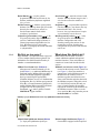
Mildata/místní volící spínač (Obrázek 6)—Je
umístěný v ovládací skříni mikroprocesoru
(viz. Obrázek 1), přičemž umožňuje stroji
komunikovat se sítí Mildata. Mildata síť
spojuje několik strojů dohromady a
umožňuje jim sdílet prací programy a jiná
data s počítačem Mildata. Když je tento
spínač Mildata v poloze(-) a zadáš-li číslo
programu, tak stroj si vyžádá obsah
programu z Mildata počítače. Když nastavíš
do Místní polohu (_), tak jsou k dispozici
pouze přítomné programy Ve stroji.
Other buttons and switches are used to
control additional standard and optional
machine functions. These miscellaneous
controls are located and described in this
section.
Mildata/Local selector switch (Figure 6)—
located on the microprocessor control box
(see Figure 1), allows the machine to
communicate with a Mildata network. A
Mildata network connects several
machines together and allows them to
share wash formulas and other data with
the Mildata computer. When this switch
is in the Mildata position (-) and you
enter a formula number, the machine
requests the contents of the formula from
the Mildata computer. When set to the
Local position (_), only formulas present
in the machine are available.
Obrázek [Figure] 6: Mildata/místní volící spínač [Mildata/Local Selector switch]
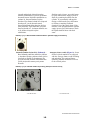
Tlačítko ručního napouštění (Obrázek 7)—
Na strojích vybavených volitelným
PELLERIN MILNOR CORPORATION
38
Manual supply flush button (Figure 7)—
On machines equipped with an optional
Kapitola 1. Ovladače
a strojích vybavených volitelným injektorem
napouštění, stiskni toto tlačítko ke vstříknutí
vody do injektoru pro naplnění jakýchkoliv
zbývajících chemikálií (pracích prostředků)
do válce. Jestliže přidáš ručně dávku během
pracího programu, stiskni toto tlačítko ke
spláchnutí zbývajících nerozpuštěných
chemikálií pryč ze skluzavky. Není-li stroj
vybaven tímto volitelným injektorem, stiskni
toto tlačítko, aby se smísily kapalné
chemikálie (prací prostředky) s čerstvou
vodou.
n machines equipped with an optional
flushing supply injector, press this button
to spray water into the supply injector to
flush any remaining chemicals into the
cylinder. If you manually add supplies
during a wash formula, press this button
to flush any remaining undiluted
chemicals out of the supply chute. If the
machine is not equipped with the optional
supply injector, press this button to flush
the liquid chemical inlets with fresh
water.
Obrázek [Figure] 7: Tlačítko ručního napouštění [Manual Supply Flush button]
Volící spínač Autospotu (Obrázek 8)—
Některé stroje s děleným válcem jsou
vybaveny Autospot možností k získání
nakládky a vykládky. Tato volitelná možnost
optimálně polohuje koš kvůli přístupu na
volitelný žok.
Autospot selector switch (Figure 8)—Some
divided-cylinder machines are equipped
with the Autospot feature to aid in loading
and unloading. This optional feature
optimally positions the basket for access
to the selected pocket.
Obrázek [Figure] 8: Volící spínač Autospotu [Autospot selector switch]
— Konec BICWCO02 —
— End of BICWCO02 —
PELLERIN MILNOR CORPORATION
39
Kapitola 2. Normální operace
Kapitola 2
Chapter 2
Normální operace
Normal
Operation
BICWCO03 (Published) Book specs- Dates: 20070515 / 20070515 / 20080521 Lang: CZE01 Applic: CWS
2.1.
Pracovní instrukce pro
obslužný personál
Operating Instructions for
Plant Personnel
2.1.1.
Zde startuj kvůli bezpečnosti
Start Here for Safety
Tento dokument je míněn aby ti připomenul
coby osobě obsluhující tuto pračku, co se
požaduje k ovládání tohoto stroje. Nepokoušej
se řídit tento stroj dříve než ti zkušený a školený
operátor vysvětlí detaily.
This document is meant to remind you, the
person operating this washer extractor, of
what is required to operate this machine. Do
not attempt to operate this machine before an
experienced, trained operator explains the
details to you.
NEBEZPEČÍ 2 : Mnohonásobné
nebezpečí—Nebezpečné akce operátora
mohou zabít nebo zranit personál, poškodit nebo
zničit stroj, poškodit majetek a/nebo zneplatnit
záruky.
DANGER 2 : Multiple Hazards—
Careless operator actions can kill or injure
personnel, damage or destroy the machine,
damage property, and/or void the warranty.
NEBEZPEČÍ 3 : Elektroúraz a nebezpečí
požáru elektřinou—Kontakt s elektřinou tě
může zabít nebo vážně zranit. Elektřina je uvnitř
skříně i pokud je hlavní spínač stroje rozpojen.
• Neodjišťuj a neotvírej dveře elektrické
skříně.
• Pamatuj si umístění hlavního přípoje
stroje a použij jej v nouzi, abys vypnul
kompletně elektřinu ve stroji.
• Neobsluhuj stroj pokud nejsi
kvalifikovaný a nemáš to dovoleno.
Musíš jasně porozumět nebezpečím a
vědět jak jim předcházet.
DANGER 3 : Electrocution and
Electrical Burn Hazards—Contact with
electric power can kill or seriously injure
you. Electric power is present inside the
cabinetry unless the main machine power
disconnect is off.
• Do not unlock or open electric box
doors.
• Know the location of the main
machine disconnect and use it in an
emergency to remove all electric
power from the machine.
• Do not service the machine unless
qualified and authorized. You must
clearly understand the hazards and
how to avoid them.
PELLERIN MILNOR CORPORATION
40
Kapitola 2. Normální operace
2.1.2.
POZOR 4 : Nebezpečí kolize,
rozmačkání a skřípnutí.—Kontakt
s pohyblivými komponenty, normálně
izolovanými kryty a panely může vtáhnout a
rozmačkat vaše končetiny. Tyto komponenty se
hýbou automaticky.
CAUTION 4 : Collision, Crushing and
Pinch Hazards—Contact with moving
components normally isolated by guards,
covers, and panels, can entangle and crush
your limbs. These components move
automatically.
Nastavení kontrolního spínače
Check Switch Settings
Displej nebo akce
[Display or Action]
R
m/M
2.1.3.
Vysvětlení
Explanation
Kontroluj, že spínač
Běh/program je v R.
Check that the run/program
keyswitch is at R.
Všechna nouzová stop tlačítka
musí být uvolněna a v
Připraven pozici, aby
dovolovala funkci stroje.
All emergency stop buttons
must be unlatched and in the
ready position to allow
machine operation.
Zkontroluj, že hlavní spínač je v
M.
Check that the master switch
is at M.
Jak mohu naložit StaphGuard®
stroj?
Displej nebo akce
[Display or Action]
d+l
!
l+1
Vysvětlení
Explanation
Otevři Venkovní dveře.
Open the outer door.
Zvol žok k naložení.
Select a pocket to load.
Ustav zvolený žok k vnějším
dveřím.
Align the selected pocket
with the outer door.
Otevři vnitřní dveře k naložení
prvního žoku.
Open the inner door of the
first pocket to load.
Použij postup definovaný vedením provozovny
k vložení prádla do stroje.
Use the procedure defined by facility
management to put the goods in the machine.
Uzavři a zamkni vnitřní dveře.
Close and latch the inner
door.
Otevři vnitřní dveře k naložení
prvního žoku.
Open the inner door of the
first pocket to load.
Ověř že všechny žoky jsou naloženy podobným
zbožím přibližně stejné váhy.
2.1.4.
How do I Load a StaphGuard®
Machine?
Jak mám zvolit program?
Kontrolér Mark VI může pracovat buď v Místní
nebo Mildata režimu. V Místní režimu, stroj
nekomunikuje s žádnými jinými zařízeními a
Verify that all pockets are loaded with
similar goods to about the same weight.
How do I Select a Formula?
The Mark VI controller can operate in either
local or Mildata mode. In local mode, the
machine does not communicate with any
PELLERIN MILNOR CORPORATION
41
Kapitola 2. Normální operace
provádí programy obsažené v místní paměti
kontroléru. V Mildata režimu, stroj nahraje a
provádí programy z Mildata počítače a ty
opakovaně se zobrazují na displeji Mildata
počítače.
other devices and runs formulas contained in
local controller memory. In Mildata mode
the machine downloads and runs formulas
from the Mildata computer, and frequently
updates the display on the Mildata computer.
Obrázek [Figure] 9: Volí místní nebo externí programy [Selecting a Local or Remote Formula]
Zvol Program Displeje (nebo zobrazuje) [Select Program
Displays]
Legenda [Legend]
A.
B.
Místní (Mildata nejsou
nebo nejsou umožněna)
[Local (Mildata not
present or enabled)]
Externí (Mildata
neumožněna) [Remote
(Mildata enabled)]
.
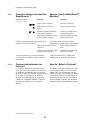
2.1.4.1.
Volí místní program—Jestliže stroj není
částí Mildata sítě, či ta není k dispozici, můžeš
vybrat jakýkoliv z pracích programů uložených
v místní paměti stroje. Použij Zvol místní
program obrazovku z (Obrázek 10) k vybrání
správného programu pro zboží ve stroji.
PELLERIN MILNOR CORPORATION
42
Selecting a Local Formula—If the
machine is not part of a Mildata network, or
if the Mildata network is not available, you
can choose from any of the wash formulas
stored in local memory on the machine. Use
the Select Local Formula screen (Figure 10)
to choose the correct formula for the goods
in the machine.
Kapitola 2. Normální operace
Obrázek [Figure] 10: Zvol místní program obrazovka [Select Local Formula Screen]
Displej nebo akce
[Display or Action]
Vysvětlení
Explanation
Přímo zvol program, který
chceš nechat běžet (07,
například). Když zapíšeš
dvouciferné číslo, zvolený
program se objeví na vršku
levého sloupce této obrazovky.
Directly selects the formula
you want to run (07, for
example). When you enter a
two-digit number, the
selected formula moves to
the top of the left column on
this screen.
k
Přiřadí řádek pro volbu
programu je-li to nutné. Jestliže
požadovaný program je vidět na
obrazovce, ale je v opačném
řádku mimo volící box, tak
stlačením tlačítka přeřadíš
volící box do druhého (dalšího)
řádku programu.
Toggles the column for
formula selection if
necessary. If the desired
formula is visible on the
screen, but is in the opposite
column from the selection
box, this keystroke moves
the selection box to the other
column of formulas.
&/^
Běž na další nebo předchozí
zobrazený program v běžícím
řádku. Je-li požadovaný
program vidět na obrazovce a
v tom samém sloupci jako
volící box, můžete použít tyto
dvě klávesy k přesunutí volícího
boxu dolů nebo nahoru k volbě
programu.
Move to the next or previous
displayed formula in the
current column. If the
desired formula is visible on
the screen and in the same
column as the selection box,
you can use these two keys
to move the selection box
down or up to select the
formula.
07
PELLERIN MILNOR CORPORATION
43
Kapitola 2. Normální operace
Displej nebo akce
[Display or Action]
u
Vysvětlení
Explanation
Potvrď zvolený program.
Umísti volící box na program
co chceš provádět, pak stiskni u
pro pokračování v normálních
operačních procedurách.
Confirm the selected
formula. Place the selection
box on the formula you want
to run, then press u to
continue with the normal
operation procedures.
Příloha 1
Supplement 1
O váze nákladu a Odměřená voda
About Load Weight and Metered
Water
Měřená voda je na Mark VI pračce opatřená
volitelným průtokovým měřidlem na přívodu
vody. Toto vybavení umožňuje kontroléru
Mark VI přivádět množství vody úměrně
k váze zboží které jsi zapsal (vložil) po
zvolení programu. Jestli jsi hned zapsal váhu
200 jednotek, tak stroj použije dvakrát tolik
vody a to tolik, jako kdyby jsi zapsal 100
váhových jednotek. Tato volba může ušetřit
značné množství vody jestliže zapíšeš přesně
váhy každého nákladu.
Metered water is available on Mark VI
washer-extractors equipped with optional
flow meters on the incoming water lines.
This feature allows the Mark VI controller
to admit a quantity of water proportional to
the weight of goods you enter after
selecting the formula. If you enter a weight
of 200 units when prompted, the machine
will use twice as much water as if you
entered 100 weight units. This option can
save a significant amount of water if you
enter accurate weights for each load.
PELLERIN MILNOR CORPORATION
44
Kapitola 2. Normální operace
Obrázek [Figure] 11: Zapisování váhy nákladu pro měřenou vodu [Entering Load Weight for Metered
Water]
Displej nebo akce
[Display or Action]
449
u
2.1.4.2.
Vysvětlení
Explanation
Zapiš váhu zboží naloženou do
stroje. Kontrolér stroje použije
váhu aby určil, kolik vody je
potřeba k praní v závislosti na
nastaveném programu.
Enter the weight of the
goods loaded in the machine.
The machine controller uses
the weight to determine how
much water is needed to
wash the goods according to
the programmed wash
formula.
Akceptuj zapsanou váhu zboží a
pokračuj.
Accept the entered goods
weight and continue.
Volba programu Mildata—Je-li stroj částí
Selecting a Mildata Formula—If the
Poznámka 1: Do Mildata počítače můžeš uložit až
1000 různých pracích programů. Všechny tyto
programy jsou použitelné pro všechny pračky co jsou
částí Mildata sítě a jsou kompatibilní.
Note 1: You can store up to 1000 different wash
formulas on the Mildata computer. All of these
formulas are available to all washer-extractors
that are part of the Mildata network and have
compatible hardware.
Mildata sítě a ta je k dispozici, můžeš vybrat
jakýkoliv prací program na Mildata počítači.
Použij Zvol externí program obrazovku z
(Obrázek 12) pro výběr nejlepšího programu pro
zboží ve stroji.
machine is part of a Mildata network and the
network is available, you can choose any
wash formula stored on the Mildata
computer. Use the Select Remote Formula
screen (Figure 12) to choose the best formula
for the goods in the machine.
PELLERIN MILNOR CORPORATION
45
Kapitola 2. Normální operace
Obrázek [Figure] 12: Zvol externí program Obrazovka [Select Remote Formula Screen]
Displej nebo akce
[Display or Action]
0928
u
2.1.4.3.
Vysvětlení
Explanation
Zvol program 928 (příklad)
uložený v Mildata počítači.
Mark VI kontrolér vyžaduje
program z Mildata počítače a
zobrazí jméno programu, jak
vidět v Obrázek 12.
Select formula 928
(example) stored on the
Mildata computer. The Mark
VI controller requests the
formula from the Mildata
computer and displays the
formula name, as shown in
Figure 12.
Potvrď, že zobrazené jméno
programu odpovídá programu
co chceš použít. Jestliže
zobrazený program neodpovídá
tomu pro vložené zboží, stiskni
c abys vymazal číslo programu
a pak zapiš jiné číslo.
Confirm that the displayed
formula name is the formula
you want to run. If the
displayed formula isn't the
right one for the loaded
goods, press c to clear the
formula number, then enter
another number.
Potom co jsi nahradil a ověřil program, tak
Mark VI kontrolér napoví konfigurované Data
dávky.
After you've retrieved and verified the
formula, the Mark VI controller prompts for
any configured batch data.
Zapisování Kódy dávky Mildata—Mark
Entering Mildata Batch Codes—The
Mark VI controller uses a screen similar
Figure 13 to prompt you for the batch data
fields selected in machine configuration (see
the related section in document
BICWCC01). The data you enter is sent to
the Mildata computer for accounting and
report generation.
VI kontrolér používá obrazovku podobnou s
Obrázek 13, aby napověděl pole data dávky
zvolené v konfiguraci stroje (viz Odpovídající
sekce v dokumentu BICWCC01). Data co jsi
zapsal jsou poslána do Mildata počítače pro
spočtení a nahlášení.
PELLERIN MILNOR CORPORATION
46
Kapitola 2. Normální operace
Obrázek [Figure] 13: Data dávky pro funkci externího programu [Batch Data for Remote Formula
Operation]
Váha—Váha dávky zboží ve stroji. Tato
informace se obvykle používá spolu
s ostatními údaji o dávce pro kalkulaci
nákladů zákazníka nebo produktivity
zaměstnance. U strojů vybavených
volitelným průtokovým měřidlem a
konfigurovaných pro měření vody, je
hodnota váhy také užita k určení jak moc
vody je požadováno do dávky. Hodnota váhy
může být až třímístná.
Weight—the weight of the batch of goods in
the machine. This information is usually
used along with other batch data to
calculate customer charges or employee
productivity. In machines equiped with
optional flow meters and configured for
metered water, the weight value is also
used to determine how much water is
required to process the batch. The weight
value can be up to three digits.
Kód zákazníka—Identifikační kód pro
zákazníka. Tato informace ti pomůže určit
kolik práce každý zákazník představuje. Pro
kód zákazníka je možno použít až deset
číslic.
Customer Code—the identifying code for
the customer. This information can help
you determine how much work each
customer is submitting. Ten digits are
available for customer code.
Číslo zaměstnance—Identifikační kód
zaměstnance odpovědného za dávku. Číslo
zaměstnance může mít až pět čísel.
Employee Number—the identifying code
for the employee responsible for this
batch. The employee number may be up
to five digits long.
Kusy—Počet kusů ve stroji. Tato hodnota
někdy nahrazuje hodnotu váhy, speciálně
když vsázky jsou provedeny podle kusů
raději než podle váhy. Pro počet kusů jsou
určeny čtyři číslice.
Pieces—the number of pieces in the
machine. This value sometimes replaces
the weight value, especially when charges
are made by the piece rather than by
weight. Four digits are available for the
number of pieces.
Číslo lotu (skupiny)—Identifikační kód pro
několik k sobě návazných (příbuzných)
dávek nebo zákazníků. Dle tvého uvážení
hodnota zde zapsaná může představovat
specielní číslo cesty k několika účtům. Číslo
lotu může mít až 10 číslic.
Lot Number—the identifying code for
several related batches or customers. At
your discretion, the value entered here
might represent a particular route number
common to several accounts. A lot
number can be up to 10 digits long.
PELLERIN MILNOR CORPORATION
47
Kapitola 2. Normální operace
2.1.5.
Startuj zvolený program
Ujisti se, že máš zkompletovány tyto kroky před
tím než budeš pokračovat v jakékoliv další
práci.
1. Máš naložen stroj přesně nebo okolo jeho
váhové kapacity.
2. Máš zvolený program vhodný pro zboží ve
stroji.
3. Máš zapsána všechna data dávky co
kontrolér stroje požaduje pro měření vody
nebo pro hlášení Mildata.
4. Máš zavřena dvířka.
Displej nebo akce
[Display or Action]
1
2.1.6.
Start the Selected Formula
Be sure you've completed these steps before
you go any further in the operating
procedure.
1. You've loaded the machine at or near its
rated weight capacity.
2. You've selected a formula that's
appropriate for the goods in the machine.
3. You've entered any batch data the
machine controller requires for metered
water or Mildata reporting.
4. You've closed the door.
Vysvětlení
Explanation
Startuj zvolený program.
Start the selected formula.
Stroj provádí program. Koš se začne otáčet a
ventily vody se otevřou. Když je dosažena
bezpečná úroveň, tak parní ventil se může
otevřít a dojde k ohřevu dávky. Proces od této
chvíle až po konec programu je kompletně
automatický, ledaže by byl naprogramován
signál pro vstřik chemikálií (pracích
prostředků). (viz. Příloha 2).
The machine begins the wash formula. The
basket begins turning and water valves open.
When a safe level is achieved, the steam
valve may open to begin heating the bath.
Operation from this point to the end of the
formula is completely automatic unless a
signal is programmed with a chemical
injection (see Supplement 2).
Příloha 2
Supplement 2
Vstříknutí chemikálií (pracích
prostředků) v návaznosti na signál
operátora.
Chemical Injections with the
Operator Signal
Jestli chceš nastavit množství pracích
prostředků od naložení do naložení
v závislosti na vysoce variabilních faktorech,
program může být nastaven tak, že zastaví
časovač a signalizuje ti, kdy se vyžaduje
chemikálie (prací prostředky). Přidej
chemikálii, pak zmáčkni A k pokračování
programu.
If you need to adjust the amount of a
chemical injection from load to load
depending on highly variable factors, the
formula can be programmed to stop the
timer and signal you when a chemical is
required. Add the chemical, then press A
to resume the formula.
Co mi displej Běh oznamuje?
Zatím co stroj běží podle programu, který jsi
zvolil, displej ukazuje to samé co je v Obrázek
14. Zde zobrazená informace je vysvětlena dole.
PELLERIN MILNOR CORPORATION
48
What Does the Run Display
Tell Me?
While the machine is running the formula
you selected, the display appears similar to
the one shown in Figure 14. The information
shown here is explained below.
Kapitola 2. Normální operace
Obrázek [Figure] 14: Jak číst displej Běh [How to Read the Run Display]
Typický displej [Typical Display]
Legenda [Legend]
A.
B.
C.
D.
E.
F.
G.
.
H.
I.
J.
K.
L.
M.
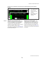
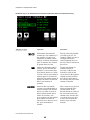
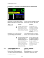
2.1.6.1.
Informace o programu a kroku—Horní
část displeje vždy ukazuje číslo a jméno
běžícího programu a kroku. Číslo programu
ukazuje v levém horním rohu displeje za
symbolem “F.” symbol Jméno programu a to
následně za číslem.
Číslo a jméno programu
[Formula number and
name]
Číslo a jméno kroku [Step
number and name]
Doba trvání programu a
běžící krok [Total time
for formula and current
step]
Grafická rotace programu
a rychlost [Basket
rotation graphic and
speed]
Zbývající čas programu a
běžící krok [Remaining
time for entire formula
and current step]
Zpráva o stavu stroje
[Machine status message]
Kroky programu: číslo,
jméno a trvání [Formula
steps: number, name, and
duration]
Indikátor plnění nebo
vypouštění [Indicator for
filling or draining]
Grafický indikátor hladiny
dávky [Graphic bath level
indicator]
Indikátory vodních ventilů
[Water valves indicators]
Indikátory ventilů
volitelné páry a
ochlazování [Indicator for
optional steam and
cooldown valves]
Grafický indikátor teploty
dávky [Graphic bath
temperature indicator]
Teplota dávky a údaje
[Bath temperature and
level data]
Formula and Step Information—The
top line of the display always shows the
number and name of the current formula and
step. The formula number appears in the
upper left corner of the display, following the
letter “F.”The formula name follows the
number.
PELLERIN MILNOR CORPORATION
49
Kapitola 2. Normální operace
Číslo a jméno běžícího kroku jsou vidět napravo
v informaci o programu. Kontrolér Mark VI
ukazuje číslo programu a jméno když program
startuje a na začátku každého následného kroku.
The step number and name of the current
step are displayed to the right of the formula
information. The Mark VI controller updates
the formula number and name when a
formula starts and at the beginning of each
subsequent step.
Pod jmény programu a kroku je Časová
informace. Čísla v “Celkem” řádku (zelená
čísla), znamenají celkový čas požadovaný pro
program a krok do dokončení, přičemž
nezahrnují faktory popsané v Poznámka 2.
Kontrolér počítá “Program” hodnotu když
program začíná, přičemž tato hodnota se nemění
když je program v běhu. Kontrolér spočte a
ukáže hodnotu “Krok x” na startu každého
kroku.
Below the formula and step names is time
information. The numbers in the “Total”
column (green numbers) show the total time
required for the formula and step to run to
completion, not including the factors
described in Note 2. The controller calculates
the “Formula” value when the formula
begins, and this value doesn't change while
the formula is running. The controller
calculates and displays the “Step x” value at
the start of each step.
Čísla ve sloupci “Zbývající” od kolonky času
(černá čísla na zeleném pozadí), indikují
Zbývající čas v programu a běžícím kroku. Tato
čísla ukazují hodnotu Minimumzbývajícího
času (viz. Poznámka 2).
The numbers in the “Remaining” column of
the time area (black numbers on a green
background) indicate the time remaining in
the formula and in the current step. These
numbers indicate the minimum amount of
time remaining (see Note 2).
Poznámka 2: Doba trvání programu nemůže být
odhadnuta a tak kontrolér zastaví časovač pokud je
požadavek splněn. Například, čas požadovaný aby
stroj napustil požadovanou hladinu, závisí na tlaku
vody v provozovně, světlosti trubek stroje a jak moc
ostatních strojů zrovna napouští. Dále, i časy
požadované pro napuštění, k dosažení teploty nebo
čas operátora k ověření a vstřiku chemikálií (pracích
prostředků), jsou proměnné. Také chyby mohou
zastavit časovač.
Note 2: The duration of some wash formula
events can't be estimated, so the controller stops
the timer until a requirement is met. For example,
the time required for the machine to fill to the
desired level depends on the water pressure to the
plant, the size of the piping to the machine, and
how many other machines are filling at the same
time. In addition to the time required to fill, the
time required to achieve temperature or for an
operator to verify a chemical injection are
variable. Error conditions can also stop the timer.
Kontrolér ukazuje běžící Stav stroje a to pod
číslem kroku a zbývajícím časem. Některé
z možných stavů stroje jsou uvedeny v Tabulka
1. Chybové zprávy se objevují ihned pod
zprávou o stavu stroje, když se to požaduje.
The controller displays the current machine
status below the step number and remaining
time. Some of the possible machine states are
listed in Table 1. Error messages appear
immediately below the machine status
message when required.
Tabulka 1: Zpráva o stavu stroje [English table follows]
Prázdný (nepracující?)
Volný doběh
1-způsob praní
Čekám na vypouštění
2-způsob praní
Čekám na naložení
Namáčení
Zpoždění pohonu ?
Přípravné+Konečné ždímání
Vypouštění do kanalizace
Meziždímání
Vypouštění k dalšímu použití
Konečné ždímání
Časovač zastaven
Dvojité ždímání
Prosím počkejte xx vteřin
PELLERIN MILNOR CORPORATION
50
Kapitola 2. Normální operace
Table 1: Machine Status Messages
Idle
Coasting
1-way Wash
Waiting to Discharge
2-way Wash
Waiting for Load
Soak
Power-up Delay
Pre+Final Extract
Draining to Sewer
Intermediate Extract
Draining to Reuse
Final Extract
Timer Stopped
Double Extract
Please Wait xx Seconds
2.1.6.2.
Rotace koše—Grafická rotace koše
umístěné blízko horního pravého rohu displeje,
reprezentuje relativní rychlost koše při praní,
vypouštění a rychlosti ždímání. Hned pod
grafickou rotací koše, uvádí kontrolér
požadovanou rychlost koše a to budˇ v otáčkách
za minutu (RPM), nebo v gravitačních
jednotkách (G's).
Basket Rotation—The basket rotation
graphic near the upper right corner of the
display represents the relative basket speeds
in wash, drain, and extract speeds.
Immediately below the basket rotation
graphic, the controller displays the desired
basket speed in either revolutions per minute
(RPMs) or in gravitational units (G's).
2.1.6.3.
Teplota dávky a hladina—Indikátory
vodních ventilů se objeví když je odpovídající
vodní ventil otevřen.
Bath Temperature and Level—Water
Graf Indikátor teploty dávky ukazuje přibližnou
teplotu ve stroji. Vertikální ukazatel indikátoru
je zcela červený kdy je teplota stroje na maximu
z povolené hodnoty 205 stupňů Fahrenheita (95
stupňů Celsia).
The graphic bath temperature indicator
shows the approximate temperature in the
machine. The vertical indicator bar is solid
red when the temperature in the machine is at
the maximum allowable value of 205 degrees
Fahrenheit (95 degrees Celsius).
Indikátor páry a ochlazování je pod grafickým
indikátorem teploty a to v případě když jsou
instalovány na přání. “Pára” se objeví když se
otevře parní ventil, a “Ochlazování” se objeví
když je vydán povel pro ochlazování.
The steam or cooldown indicator appears
below the graphic temperature indicator
when either of these optional features is
enabled. “Steam” appears when the steam
valve is open, and “Cooldown” appears when
the cooldown output is enabled.
Graf Indikátor hladiny dávky ukazuje procentní
podíl naplnění požadované hladiny. Vertikální
ukazatel je zcela modrý, když je nastavená
hladina dosažena, a úplně bílý když ve stroji
není žádná voda.
The graphic bath level indicator shows the
percentage of the desired level that's
achieved. The vertical indicator bar is solid
blue when the programmed level is achieved,
and solid white when there is no water in the
machine.
Šipka indikátoru směru hladiny ukazuje nahoru
když aktuální hladina ve stroji stoupá (stroj se
napouští), a dolů když se vypouští. Šipka není
vidět když je hladina dosažena, nebo během
ždímání.
The level direction indicator arrow points
upward when the actual bath level in the
machine is increasing (when the machine is
filling), and points downward when the drain
opens. The arrow is not visible when level is
achieved, or during extract steps.
Kontrolér ukazuje Údaje o teplotě vody a
hladině údaje teploty a grafických indikátorů
The controller displays bath temperature and
level data between the temperature and level
valve indicators appear when the
corresponding water valve is open.
PELLERIN MILNOR CORPORATION
51
Kapitola 2. Normální operace
2.1.6.4.
2.1.7.
hladiny. Horní řádek ukazuje teplotu a hladinu
co jsou teď na stroji a spodní řádek pak
požadované hodnoty.
graphic indicators. The top line displays the
temperature and level that are currently
achieved in the machine, and the bottom line
displays the desired values.
Kroky programu a vstřik pracích
prostředků—Když program začíná, kontrolér
Formula Steps and Chemical
Injection—When a formula begins, the
ukazuje prvních šest kroků v Seznam kroků
programu na spodní levé oblasti obrazovky.
Jestli program má více kroků než může být
ukázáno současně, jejich seznam roluje a ukáže
více kroků až po skončení předchozích. Běžící
krok je zvýrazněn.
controller displays the first six steps in the
formula steps list in the lower left area of the
screen. If the program contains more steps
than can be displayed at one time, the list
scrolls to display more steps as the earlier
ones end. The current step is highlighted.
Seznam naprogramovaných Vstřikování pracích
prostředků nahradí seznam kroků programu
během každého vstřiku a to se zvýrazněným
políčkem chemikálie (pracího prostředku),
která je právě aplikována.
The list of programmed chemical injections
replaces the formula steps list during each
injection, with a highlight box on the
chemical that's currently injecting.
Vylož stroj
Unload the Machine
Když program skončí, zazní signál operátora a
stroj zobrazí hlášení, že čeká na vyprázdnění
(viz. Obrázek 15). Provedˇ proceduru podobnou
té uvedené dole pro vyložení zboží.
When the formula ends, the operator signal
sounds and the machine displays a message
that it is waiting to discharge (see Figure 15).
Use a procedure similar to the one outlined
below to unload the goods.
Obrázek [Figure] 15: Typická zpráva když program skončí [Typical Message when Formula Ends]
PELLERIN MILNOR CORPORATION
52
Kapitola 2. Normální operace
2.1.7.1.
Pro jakoukoliv Koncový kód—Kontrolér
Mark VI ti dovolí programovat jednu ze čtyř
možných akcí pro zakončení programu:
Zastavený, Reversující při prací rychlosti,
Otáčející se při vypouštěcí rychlosti, nebo
Máchání. Použij tu samou vykládací proceduru
pro programy jež provádějí první tři akce. Pro
čtvrtou akci musíš mít vybavení k proceduře
popsané v Sekce 2.1.7.2.
Displej nebo akce
[Display or Action]
l
0/A/
l+d
For any End Code—The Mark VI
controller allows you to program one of four
possible actions for the end of the formula:
stopped, reversing at wash speed, turning at
drain speed, or tumbling. You use the same
unloading procedure for formulas using the
first three actions. For the fourth action, you
also have the option of using the procedure
described in Section 2.1.7.2.
Vysvětlení
Explanation
Vypni 3-fázový obvod, signál
operátora, zastav jakýkoliv
pohyb koše. Toto tlačítko také
odemkne dveře a tak je můžeš
otevřít.
Remove power from the 3wire circuit, silence the
operator signal, and stop any
basket motion in progress.
This button also unlocks the
door so you can open it.
Také můžeš vypnout 3-fázový
obvod, signál operátora a
zastavit pohybující se koš
jakýmkoliv z těchto tlačítek.
Ale, když použiješ jakékoliv
z těchto tlačítek, tak budeš
potřebovat odblokovat dveře
pomocí l předtím než je
otevřeš. Při použití kteréhokoli
z těchto tlačítek k ukončení
programu s Koncový kód 3
(viz. Sekce 2.1.7.2), se program
ukončí a nemůže se v něm
pokračovat.
You can also remove power
from the 3-wire circuit,
silence the operator signal,
and stop any basket motion
that was in progress with any
of these buttons. However, if
you use any of these buttons,
you'll still need to unlock the
door with l before you can
open it. If you use any of
these buttons to stop a
formula with end code 3 (see
Section 2.1.7.2), the formula
is terminated and cannot be
resumed.
Otevři dveře pro vykládku.
Open the door for unloading.
PELLERIN MILNOR CORPORATION
53
Kapitola 2. Normální operace
2.1.7.2.
pro koncový kód 3 (Máchání)—
Koncový kód 3 (Máchání) ti umožní otevřít
dveře a vyjmout zboží, pak zavři dveře a
dokonči máchání pro vyjmutí dalšího zboží z
koše.
Displej nebo akce
[Display or Action]
l
Explanation
Vypni 3-fázový obvod, signál
operátora, zastav jakýkoliv
pohyb koše. Toto tlačítko také
odemkne dveře a tak je můžeš
otevřít.
Remove power from the 3wire circuit, silence the
operator signal, and stop any
basket motion in progress.
This button also unlocks the
door so you can open it.
1
When the basket stops turning, open the door
and remove some or all of the goods from the
machine.
Otevři dveře pro vykládku.
Vyjmi požadovanou část z dávky.
D+l
code 3 (Tumbling) allows you to open the
door and remove some of the goods, then
close the door and resume tumbling to loosen
more goods from the basket.
Vysvětlení
Když koš zastaví, otevři dveře a vyjmi jen
některé kusy nebo všechno zboží ze stroje.
l+d
For End Code 3 (Tumbling)—End
Open the door for unloading.
Remove any desired portion of the load.
Zavři dveře.
Close the door.
Dokončuje máchání bez signálu
operátora. Máchání pokračuje
po další dvě minuty, nebo než
zmáčkneš l.
Resumes the tumbling action
without the operator signal.
Tumbling continues for
another two minutes, or until
you press l.
— Konec BICWCO03 —
— End of BICWCO03 —
PELLERIN MILNOR CORPORATION
54
Kapitola 3. Signály a chyby
Kapitola 3
Chapter 3
Signály a chyby
Signals and
Errors
BICWCT04 (Published) Book specs- Dates: 20070515 / 20070515 / 20080521 Lang: CZE01 Applic: CWS
3.1.
Zásah operátora
Operator Intervention
3.1.1.
Chyba ve spojitosti se signálem
operátora
Error with Operator Signal
Jakmile program nastartuje, stroj obvykle běží
automaticky. Stroj signalizuje zvukem jestliže
operátor potřebuje něco rozhodnout, nebo udělat
něco ručně. Nejběžnější důvod, že je třeba
obsloužit stroj je v mnoha případech chyba a
pak ruční přidání chemikálií (pracích
prostředků).
Signál operátora zazní a signálka bliká, když
stroj zastaví tato chyba. Tato chyba obvykle
vypne třífázový obvod a spustí bezpečnostní
vibrační spínač, nebo způsobí nefunkčnost
měniče co řídí motor. Obrázek 16 se objeví
když je displeji chyba vibračního spínače.
Once a formula starts, the machine usually
runs automatically. The machine will sound
the signal if an operator needs to make a
decision or do something manually. The
most common reasons you'll need to attend
to the machine are errors, and to manually
add chemicals in some cases.
The operator signal will sound and the
beacon will flash if an error causes the
machine to stop. These errors usually disable
the three-wire circuit, and include a tripped
vibration switch or a malfunction of the
inverter that controls the motor. Figure 16
shows how a vibration switch error appears
on the display.
PELLERIN MILNOR CORPORATION
55
Kapitola 3. Signály a chyby
Obrázek [Figure] 16: Typická chyba v souvislosti se signálem operátora [Typical Error with Operator
Signal]
Pro pokračování programu vypni signál a oprav
příčinu chyby. Pak restartuj program.
Displej nebo akce
[Display or Action]
A
Vysvětlení
Explanation
Tlačítko Cancel na klávesnici
zastaví stroj, vypne bzučák
signálu operátora a zhasne
signálku. Musíš restartovat
program od začátku.
The Cancel key on the
keypad stops the machine,
silences the operator signal
buzzer, and turns off the
signal light. You'll have to
restart the formula from the
beginning.
Correct the cause of the error. If you don't
know how to fix the problem, have someone
check the reference manual for the machine.
Oprav příčinu chyby. Jestli nerozumíš jak
vyřešit problém , nechťˇ někdo zkontroluje
referenční manuál stroje.
1
3.1.2.
To resume the formula, silence the signal and
correct the cause of the error. Then, restart
the formula.
Opravíš-li chybu, pak Start
tlačítko pokračuje v programu
od momentu zastavení.
Způsobil-li chybu vibrační
spínač, tak stroj provede
distribuční krok aby rozmístil
zboží po obvodě koše, pak
pokračuje v přerušeném kroku
vypouštění.
Signál operátora pro chemikálie
(prací prostředky)
Stroj může řídit automatický čerpadlový systém
pracích prostředků, nebo ti signalizovat ruční
přidání chemikálií. Displej (Obrázek 17) hlásí to
samé v jiném případě, ale signál operátora zazní
jen je –li naprogramován.
PELLERIN MILNOR CORPORATION
56
If you've corrected the error,
the Start button resumes the
formula where it stopped. If
the vibration switch caused
the error, the machine goes
through a distribution
sequence to spread the goods
around the basket, then
resumes the interrupted
extract step.
Operator Signal for a
Chemical
This machine can control an automatic
chemical pump system, or it can signal you
to add chemicals manually. The display
(Figure 17) appears the same in either case,
but the operator signal sounds only if the
Kapitola 3. Signály a chyby
signal is programmed.
Je-li program nastaven aby řídil čerpadlo
pracích prostředků, displej ukáže číslo
naprogramovaného ventilu pro chemikálie,
název chemikálie a čas vstřiku. Čas vstřiku,
ukázaný napravo na displeji chemikálií, začíná
odpočítávat ihned se začátkem vstřiku.
If the formula is programmed to control a
chemical pump system, the display shows the
programmed chemical valve number,
chemical name, and injection time. The
injection time, shown at the right end of the
chemical display, begins counting down
immediately when the chemical injection
begins.
Je-li program nastaven aby ti signalizoval ruční
přidání chemikálie, stroj bude běžet automaticky
až do doby potřeby chemikálie, pak stroj
zastaví, počká na tebe než přidáš a dokončí
operaci. Displej se přepne a ukáže ti kterou
chemikálii přidat, ale čítač doby vstřiku běží
jedině když zrušíš signál operátora.
If the formula is programmed to signal you
to manually add chemicals, the machine will
operate automatically until it needs a
chemical, then the machine stops and waits
for you to add the chemical and resume
operation. The display changes to show you
which chemical to add, but the injection time
counter runs only after you cancel the
operator signal.
Obrázek [Figure] 17: Pohled na vstřik pracích prostředků na běžícím displeji [Chemical Injection
View on Run Display]
Displej nebo akce
[Display or Action]
Vysvětlení
Explanation
Potom co jsi přidal chemikálii,
A
After you've added the chemical,
Zruší signál operátora a
nastartuje čítač času
vstřikování.
— Konec BICWCT04 —
cancels the operator signal
and starts the injection time
counter.
— End of BICWCT04 —
PELLERIN MILNOR CORPORATION
57
Français
59
3
Published Manual Number: MQCWSO01FR
•
•
•
•
•
•
•
Specified Date: 20070515
As-of Date: 20070515
Access Date: 20100405
Depth: Detail
Custom: n/a
Applicability: CWS
Language Code: FRE01, Purpose: publication, Format: 2colA
Guide de l’opérateur [Operator
Guide]—
StaphGuard® Laveuse-essoreuse
avec contrôleur Mark VI
[StaphGuard® Washer-extractor
with Mark VI Controller]
ATTENTION: Les informations contenues dans ce manuel ont été fournies
par Pellerin Milnor Corporation dans le version anglaise uniquement.
Milnor a souhaité obtenir une traduction de qualité, mais ne peut alléguer, ni
promettre, ni garantir l’exactitude, l’intégralité ou la qualité des informations
contenues dans la version non-anglaise.
De plus, Milnor n’a pas cherché à vérifier les informations contenues dans la
version non-anglaise, celle-ci ayant été entièrement réalisée par une tierce
partie. En conséquence, Milnor dénie expressément toute responsabilité en
ce qui concerne les erreurs de substance ou de forme et n’assume aucune
responsabilité quand à la fiabilité de l’usage des informations contenues
dans la version non-anglaise, ou aux conséquences de cet usage.
En aucune circonstance, Milnor, ses représentants ou ses
administrateurs, ne seront tenus pour responsables de tout dommage
direct, indirect, accidentel, répressif ou conséquent pouvant résulter,
de quelque façon que ce soit, de l’usage de la version non-anglaise de
ce manuel ou de l’impossibilité de l’utiliser ou de sa fiabilité ou
résultant de fautes, d’omissions ou d’erreurs dans la traduction.
Lire le manuel de sécurité
PELLERIN MILNOR CORPORATION
61
POST OFFICE BOX 400, KENNER, LOUISIANA 70063 - 0400, U.S.A.
Produits applicables de Milnor® par numéro de type: [Applicable
Milnor® products by model number:]
42044SP2
42044SP3
60044SP2
60044SP3
62
72044SP2
Table des Matières
Table des Matières
[English table of contents follows]
Sections
Illustrations, Tableaux, et Suppléments
Chapitre 1. Contrôles
1.1. Contrôles sur Marque VI Non basculanteles laveusesessoreuses (Document BICWCO02)
1.1.1. Que sont les Contrôles ?
1.1.2. Où dois-je connecter le Système de Stockage des Données
?
1.1.3. Que sont les Organes de Contrôle ?
1.1.4. A quoi sert cet interrupteur ?
Illustration 1: Emplacement des contrôles
Illustration 2: Connexion sérielle pour le
transfert des données
Illustration 3: Marque VI Contrôles
latéraux Staph Guard
Illustration 4: Clavier
Illustration 5: Contrôles latéraux Staph
Guard typiques
Illustration 6: Mildata/interrupteur
commutateur local
Illustration 7: Bouton de rinçage manuel
Illustration 8: Sélecteur Autospot
Chapitre 2. Fonctionnement normal
2.1. Instructions pour le personnel de l’usine (Document BICWCO03)
2.1.1. Commencez ici par sécurité
2.1.2. Contrôlez les positions des commutateurs
2.1.3. Comment charger une machine StaphGuard® ?
2.1.4. Comment sélectionner une formule?
Illustration 9: Sélection d’une formule
locale ou distante
2.1.4.1. Sélection d’une formule locale
Illustration 10: Sélectionner une formule
locale Ecran
Supplément 1: Poids de la charge et
Débitmètre
Illustration 11: Introduire le poids de la
charge pour le débitmètre
2.1.4.2. Sélection d’une formule Mildata
Illustration 12: Sélection d’une formule
distante Ecran
2.1.4.3. Introduction Codes de la charge de linge Mildata
Illustration 13: Données de la charge de
linge pour l’accomplissement de la
formule distante
2.1.5. Lancer la formule sélectionnée
Supplément 2: Injections chimiques avec
signal opérateur
2.1.6. Quelle est la signification de l’affichage de l'écran
Illustration 14: Comment lire l’écran
Démarrage ?
Démarrage ?
2.1.6.1. Informations relatives à la formule et à l'étape
Tableau 1: Messages relatifs à l’état de la
machine
2.1.6.2. Rotation du tambour
PELLERIN MILNOR CORPORATION
63
Table des Matières
Sections
Illustrations, Tableaux, et Suppléments
2.1.6.3. Température et niveau du bain
2.1.6.4. Etapes de la formule et injection chimique
2.1.7. Décharger la machine
Illustration 15: Message typique affiché à
la fin de la formule
2.1.7.1. Pour chaque Code de fin
2.1.7.2. Pour terminer le code 3 (Séchage)
Chapitre 3. Signaux et erreurs
3.1. Intervention de l’opérateur (Document BICWCT04)
3.1.1. Erreur avec signal opérateur
3.1.2. Signal opérateur pour un produit chimique
PELLERIN MILNOR CORPORATION
64
Illustration 16: Erreur typique avec signal
opérateur
Illustration 17: Injection des produits
chimiques : Ecran de visualisation du
déroulement du programme
Table of Contents
Table of Contents
Sections
Figures, Tables, and Supplements
Chapter 1. Controls
1.1. Controls on Mark VI Non-Tilting Washer-extractors
(Document BICWCO02)
1.1.1. Where are the Controls?
1.1.2. Where do I Connect the Data Storage Device?
1.1.3. What are the Operating Controls?
1.1.4. What does this Switch do?
Figure 1: Locations of Controls
Figure 2: Serial Connection for Data
Transfer
Figure 3: Mark VI Staph Guard Soil Side
Controls
Figure 4: Keypad
Figure 5: Typical Staph Guard Clean Side
Controls
Figure 6: Mildata/Local Selector switch
Figure 7: Manual Supply Flush button
Figure 8: Autospot selector switch
Chapter 2. Normal Operation
2.1. Operating Instructions for Plant Personnel
(Document
BICWCO03)
2.1.1.
2.1.2.
2.1.3.
2.1.4.
Start Here for Safety
Check Switch Settings
How do I Load a StaphGuard® Machine?
How do I Select a Formula?
2.1.4.1. Selecting a Local Formula
2.1.4.2. Selecting a Mildata Formula
2.1.4.3. Entering Mildata Batch Codes
2.1.5. Start the Selected Formula
2.1.6. What Does the Run Display Tell Me?
2.1.6.1. Formula and Step Information
2.1.6.2. Basket Rotation
2.1.6.3. Bath Temperature and Level
2.1.6.4. Formula Steps and Chemical Injection
2.1.7. Unload the Machine
Figure 9: Selecting a Local or Remote
Formula
Figure 10: Select Local Formula Screen
Supplement 1: About Load Weight and
Metered Water
Figure 11: Entering Load Weight for
Metered Water
Figure 12: Select Remote Formula Screen
Figure 13: Batch Data for Remote Formula
Operation
Supplement 2: Chemical Injections with
the Operator Signal
Figure 14: How to Read the Run Display
Table 1: Machine Status Messages
Figure 15: Typical Message when Formula
Ends
PELLERIN MILNOR CORPORATION
65
Table of Contents
Sections
Figures, Tables, and Supplements
2.1.7.1. For any End Code
2.1.7.2. For End Code 3 (Tumbling)
Chapter 3. Signals and Errors
3.1. Operator Intervention (Document BICWCT04)
3.1.1. Error with Operator Signal
Figure 16: Typical Error with Operator
Signal
Figure 17: Chemical Injection View on
Run Display
3.1.2. Operator Signal for a Chemical
PELLERIN MILNOR CORPORATION
66
Chapitre 1. Contrôles
Chapitre 1
Chapter 1
Contrôles
Controls
BICWCO02 (Published) Book specs- Dates: 20070515 / 20070515 / 20100405 Lang: FRE01 Applic: CWS
1.1.
1.1.1.
Contrôles sur Marque VI Non
basculanteles laveusesessoreuses
Controls on Mark VI NonTilting Washer-extractors
Se réfère à d'autres chapitres de ce document
(Section 1.1.2 à Section 1.1.4), pour
l’emplacement et les fonctions basiques des
contrôles individuels. N’utilisez pas ce
document à titre d’instructions pour faire
fonctionner la machine.
Refer to other parts of this document (Section
1.1.2 through Section 1.1.4) for the location
and basic function of individual controls.
Don't use this document as instructions for
operating the machine.
Que sont les Contrôles ?
Where are the Controls?
Les principaux contrôles pour une utilisation
normale se trouvent sur le tableau de commande
avant (). Les autres contrôles et connexions se
trouvent ailleurs sur la machine, comme cela est
décrit ici.
The essential controls for normal operation
are located on the front control panel (Figure
1). Additional controls and connections are
located elsewhere on the machine, as
described here.
PELLERIN MILNOR CORPORATION
67
Chapitre 1. Contrôles
Illustration [Figure] 1: Emplacement des contrôles [Locations of Controls]
Vue avant gauche [Front Left
View]
Vue arrière [Rear View]
Légende [Legend]
A.
B.
C.
.
D.
E.
1.1.2.
Microprocesseur de
l’armoire de commande
(68036F_B montré)
[Microprocessor control
box (68036F_B shown)]
Panneau de commande
[Control panel]
Bouton de rinçage manuel
[Manual supply flush
button]
Contrôle de la pression du
système hydraulique de la
porte pour le chargement
[Hydraulic pressure
gauge for loading door]
Manomètre du système de
basculement (à l'arrière
du panneau inférieur
arrière) [Air pressure
gauge for tilt system
(behind lower rear
panel)]
Où dois-je connecter le
Système de Stockage des
Données ?
Where do I Connect the Data
Storage Device?
Le boîtier du microprocesseur se trouve dans le
coin supérieur arrière de la machine, panneau
gauche (voir Illustration 1) et contient une
connexion DIN pour les communications
sérielles. Utilisez cette connexion, marquée
comme indiqué dans Illustration 2, avec un
appareil sériel de transfert de données pour
enregistrer ou restaurer la programmation de la
machine et la mémoire de configuration.
The microprocessor box in the upper rear
corner of the machine left side panel (see
Figure 1) contains a DIN-type connection for
serial communications. Use this connection,
labelled as shown in Figure 2, with a serial
data transfer device to save or restore
machine programming and configuration
memory.
PELLERIN MILNOR CORPORATION
68
Chapitre 1. Contrôles
Illustration [Figure] 2: Connexion sérielle pour le transfert des données [Serial Connection for Data
Transfer]
1.1.3.
Que sont les Organes de
Contrôle ?
What are the Operating
Controls?
Les organes de contrôle primaires sont
nécessaires pour faire démarrer et arrêter la
machine, sélectionner les formules de lavage et
contrôler le fonctionnement de la machine.
The primary operating controls are required
to start and stop the machine, select wash
formulas, and monitor machine operation.
PELLERIN MILNOR CORPORATION
69
Chapitre 1. Contrôles
Illustration [Figure] 3: Marque VI Contrôles latéraux Staph Guard [Mark VI Staph Guard Soil Side
Controls]
Panneau de commande [Control Panel]
Légende [Legend]
A.
B.
C.
D.
.
E.
F.
G.
H.
I.
J.
K.
L.
PELLERIN MILNOR CORPORATION
70
Arrêt d’urgence bouton
[Emergency stop button]
Déverrouillage de la porte
bouton [Door unlock
button]
Sélecteur Jog/Autospot
interrupteur
[Jog/Autospot selector
switch]
Contrôle côté propre
indicateur [Control on
clean side indicator]
Contrôle côté sale
indicateur [Control on
soil side indicator]
Interrupteur principal
pour l’alimentation
[Master switch for
power]
boutons signal opérateur
et signal annulation
[Operator signal and
signal cancel button]
Ecran graphique à cristaux
liquides [Liquid crystal
graphic display]
Interrupteur
Démarrage/Programme
[Run/Program keyswitch]
Clavier [Keypad]
Démarrage bouton [Start
button]
Arrêt bouton [Stop button]
Chapitre 1. Contrôles
Illustration [Figure] 4: Clavier [Keypad]
Illustration [Figure] 5: Contrôles latéraux Staph Guard typiques [Typical Staph
Guard Clean Side Controls]
Panneau de commande
[Control Panel]
Légende [Legend]
A.
B.
C.
D.
E.
F.
G.
Arrêt d’urgence bouton [Emergency stop
button]
Déverrouillage de la porte bouton [Door
unlock button]
Sélecteur Jog/Autospot interrupteur
[Jog/Autospot selector switch]
Contrôle côté propre indicateur [Control on
clean side indicator]
Contrôle côté sale indicateur [Control on
soil side indicator]
Contrôle de transfert bouton [Control
transfer button]
Jog/spot bouton [Jog/spot button]
.
Bouton d’arrêt d’urgence—désactive le circuit
à trois fils. Une fois commuté, cet
interrupteur se verrouille, et vous devez lui
faire faire un quart de tour pour qu’il
revienne en position normale, afin de
permettre à la machine de fonctionner.
Emergency stop button—disables the 3wire circuit. This switch locks in when
pressed, so you must turn it a quarter turn
to allow it to return to the normal position
to allow the machine to run.
Attention 1 : Appuyez immédiatement sur le
bouton arrêt d’urgence dans toutes les situations
Notice 1 : Press the emergency stop button
immediately in any emergency situation.
PELLERIN MILNOR CORPORATION
71
Chapitre 1. Contrôles
d’urgence. Le fait d’appuyer sur ce bouton
désactive le circuit à trois fils, ce qui arrête la
machine et ouvre l'évacuation.
• Lorsque vous réenclenchez ce bouton,
vous pouvez soit annuler soit reprendre
la formule de lavage interrompue. La
formule reprend là où elle avait été
interrompue ou au début du bain
précédent, en fonction de l'état
d'avancement du programme lorsque le
bouton arrêt d’urgence fut enfoncé.
This disables the 3-wire circuit, which stops
all machine operation and causes the drain to
open.
• When you reset this button, you have
the option of cancelling or resuming
the interrupted formula. The formula
resumes where it was interrupted or at
the beginning of the previous bath
step, depending on the operation in
progress when the emergency stop
button was pressed.
Interrupteur principal pour l’alimentation
(m / M)—Coupe l’alimentation du système
de contrôle. Si vous fermez l’interrupteur
Interrupteur principal (m) alors qu’une
formule est en cours, le résultat immédiat est
similaire au fait d'appuyer sur le bouton arrêt
d’urgence : la machine s’arrête et
l’évacuation s’ouvre. A l’inverse du bouton
arrêt d’urgence, une fois la machine remise
en marche, la formule recommence au début
de l'étape au cours de laquelle l'alimentation
a été coupée, sans injection de produits
chimiques toutefois.
Master power switch (m / M)—removes
power from the control system. If you
turn the master switch off (m) while a
formula is running, the immediate result
is similar to pressing the emergency stop
button: the machine stops and the drain
opens. Unlike the emergency stop button,
resumed formulas start at the beginning of
the step in which power was lost, but
chemicals are not injected in the resumed
step.
Signal opérateur, bouton d'annulation (A)—
annule le signal opérateur. Appuyez sur ce
bouton pour couper le son de la sonnette et
éteindre le témoin lumineux signal opérateur
(voir infra) ou pour permettre l’injection
d’un produit chimique programmé
nécessitant un signal avant injection.
Operator signal cancel button (A)—
cancels the operator signal. Press this
button to silence the buzzer and turn off
the operator signal light (see below), or to
allow injection of a chemical programmed
to require a signal before injection.
Signal lumineux opérateur—indique que la
machine a rencontré une erreur ou que
l’opérateur doit effectuer une action, comme
par exemple appuyer sur le bouton
démarrage ou décharger la machine. Le
circuit signal opérateur comporte une
sonnette à l’arrière du panneau de
commande, et peut comporter une balise
lumineuse en option, distincte du panneau de
commande
Operator signal light—indicates that the
machine has encountered an error or that
the operator must perform some action,
such as pressing the start button or
unloading the machine. The operator
signal circuit includes a buzzer behind the
control panel, and may include an
optional beacon light mounted separately
from the control panel.
Ecran LCD—affiche des informations et des
conseils relatifs à l’utilisation de la machine.
Ces informations changent en fonction de
l’état de la machine et de la fonction
sélectionnée par l’opérateur.
Liquid crystal graphic display—displays
information and help about the machine.
The information on the display changes
according to the status of the machine and
the function selected by the operator.
Clavier—permet à l’opérateur de communiquer
avec le système de contrôle de la machine.
Le clavier comporte trois zones : des touches
alphanumériques, des touches générales et
des touches spécifiques à une fonction.
Keypad—allows the operator to
communicate with the machine control
system. The keypad is divided into three
areas: alphanumeric buttons, general
buttons, and function-specific buttons.
PELLERIN MILNOR CORPORATION
72
Chapitre 1. Contrôles
Chaque touche peut effectuer plus d’une
fonction, en fonction de la situation en cours
de la machine. Certaines touches sont
également utilisées en combinaisons, en vue
de fonctions supplémentaires.
1.1.4.
Each button may perform more than one
function, based on the current machine
status. Some buttons are also used in
combinations for additional functions.
Bouton de démarrage (1)—lance la formule
de lavage sélectionnée. Le bouton démarrage
alimente le circuit à trois fils permettant à la
machine de fonctionner.
Start button (1)—starts the selected wash
formula. The start button energizes the 3wire circuit to allow the machine to
operate.
Bouton d’arrêt (0)—arrête le fonctionnement
de la machine. A l’instar du bouton arrêt
d’urgence, le bouton arrêt désactive le
circuit à trois fils. Toutefois, le bouton arrêt
ne nécessite pas un ré-enclenchement manuel
après avoir été utilisé.
Stop button (0)—stops machine operation.
Like the emergency stop button, the stop
button disables the 3-wire circuit;
however, the stop button doesn't require
you to manually reset it after use.
Interrupteur à clé Démarrage/Programme
(R/P)—la position Programme permet
notamment de modifier la configuration de la
machine et les formules de lavage. En
position normale, Démarrage, les formules et
les configurations sont protégées, et les
formules peuvent être lancées.
Run/Program keyswitch (R/P)—in the
Program position, allows changes to
machine configuration and wash
formulas, among other actions. In the
normal Run position, formulas and
configuration are protected and formulas
can be run.
A quoi sert cet interrupteur ?
What does this Switch do?
D’autres boutons et commutateurs sont utilisés
pour contrôler d’autres fonctions standard et
optionnelles de la machine. Ces divers contrôles
sont présentés et décrits dans cette section.
Other buttons and switches are used to
control additional standard and optional
machine functions. These miscellaneous
controls are located and described in this
section.
Mildata/Local selector switch (Figure 6)—
located on the microprocessor control box
(see Figure 1), allows the machine to
communicate with a Mildata network. A
Mildata network connects several
machines together and allows them to
share wash formulas and other data with
the Mildata computer. When this switch is
in the Mildata position (-) and you enter
a formula number, the machine requests
the contents of the formula from the
Mildata computer. When set to the Local
position (_), only formulas present in
the machine are available.
Mildata/interrupteur de sélection
local
(Illustration 6)—situé sur le
microprocesseur de l’armoire de commande
(voir Illustration 1), et permet à la machine
de communiquer avec un réseau Mildata. Un
réseau Mildata relie plusieurs machines entre
elles et leur permet de partager des formules
de lavage et d’autres données avec
l’ordinateur Mildata. Lorsque cet interrupteur
est en position Mildata (-) et que vous
introduisez un numéro de formule, la
machine demande le contenu de la formule à
l'ordinateur Mildata. Lorsque cet interrupteur
est sur Local (_), seules les formules
présentes dans la machine sont disponibles.
PELLERIN MILNOR CORPORATION
73
Chapitre 1. Contrôles
Illustration [Figure] 6: Mildata/interrupteur commutateur local [Mildata/Local Selector switch]
Bouton de rinçage manuel (Illustration 7)—
Sur les machines équipées d’un injecteur
d’approvisionnement en option, appuyez sur
ce bouton pour pulvériser l’eau dans
l'injecteur d’approvisionnement pour rincer
les résidus chimiques se trouvant encore dans
le tambour. Si vous ajoutez manuellement
des produits pendant une formule de lavage,
appuyez sur ce bouton pour rincer les résidus
de produits chimiques non dilués dans le
tuyau d'approvisionnement. Si la machine
n’est pas équipée d’un injecteur
d’approvisionnement en option, appuyez sur
ce bouton pour rincer les arrivées de produits
chimiques liquides à l’eau claire.
Manual supply flush button (Figure 7)—
On machines equipped with an optional
flushing supply injector, press this button
to spray water into the supply injector to
flush any remaining chemicals into the
cylinder. If you manually add supplies
during a wash formula, press this button
to flush any remaining undiluted
chemicals out of the supply chute. If the
machine is not equipped with the optional
supply injector, press this button to flush
the liquid chemical inlets with fresh
water.
Illustration [Figure] 7: Bouton de rinçage manuel [Manual Supply Flush button]
Sélecteur Autospot (Illustration 8)—Certaines
machines à cylindre divisé sont équipées de
la fonctionnalité Autospot pour aider au
chargement et au déchargement. Cette
fonctionnalité optionnelle permet le
positionnement optimal du panier pour
l’accès à la poche sélectionnée.
PELLERIN MILNOR CORPORATION
74
Autospot selector switch (Figure 8)—Some
divided-cylinder machines are equipped
with the Autospot feature to aid in loading
and unloading. This optional feature
optimally positions the basket for access
to the selected pocket.
Chapitre 1. Contrôles
Illustration [Figure] 8: Sélecteur Autospot [Autospot selector switch]
— Fin BICWCO02 —
— End of BICWCO02 —
PELLERIN MILNOR CORPORATION
75
Chapitre 2. Fonctionnement normal
Chapitre 2
Chapter 2
Fonctionnement
normal
Normal
Operation
BICWCO03 (Published) Book specs- Dates: 20070515 / 20070515 / 20100405 Lang: FRE01 Applic: CWS
2.1.
Instructions pour le personnel
de l’usine
Operating Instructions for
Plant Personnel
2.1.1.
Commencez ici par sécurité
Start Here for Safety
Ce document a pour but de vous rappeler à vous
qui utilisez cet appareil, ce qu'il faut faire pour
l'utiliser correctement. N’essayez pas de
l’utiliser avant d’avoir lu le document ou avant
qu’un opérateur expérimenté et formé ne vous
explique tous les détails.
This document is meant to remind you, the
person operating this washer extractor, of
what is required to operate this machine. Do
not attempt to operate this machine before an
experienced, trained operator explains the
details to you.
DANGER 2 : Risques multiples—Toute
opération effectuée par l'opérateur sans
précaution peut tuer ou blesser le personnel,
endommager ou détruire la machine,
endommager l'installation et/ou annuler la
garantie.
DANGER 2 : Multiple Hazards—
Careless operator actions can kill or injure
personnel, damage or destroy the machine,
damage property, and/or void the warranty.
DANGER 3 : Risques d'électrocution et
de brûlure électrique—Tout contact avec le
courant électrique peut entraîner la mort ou des
blessures graves. Du courant électrique est
présent à l’intérieur de l’armoire tant que le
disjoncteur principal de l’alimentation de la
machine n’est pas activé.
Ne pas déverrouiller ou ouvrir les portes des
boîtiers électriques.
• Ne pas déverrouiller ou ouvrir les portes
des boîtiers électriques.
• Vous devez connaître l'emplacement du
disjoncteur principal et l'utiliser en cas
d'urgence pour couper le courant de la
machine.
• La maintenance doit être exclusivement
assurée par des techniciens qualifiés et
DANGER 3 : Electrocution and
Electrical Burn Hazards—Contact with
electric power can kill or seriously injure
you. Electric power is present inside the
cabinetry unless the main machine power
disconnect is off.
• Do not unlock or open electric box
doors.
• Know the location of the main
machine disconnect and use it in an
emergency to remove all electric
power from the machine.
• Do not service the machine unless
qualified and authorized. You must
clearly understand the hazards and
how to avoid them.
PELLERIN MILNOR CORPORATION
76
Chapitre 2. Fonctionnement normal
agréés. Il est impératif de bien connaître
les dangers encourus et la manière de les
éviter.
2.1.2.
ATTENTION 4 : Danger de Collision,
Ecrasement et Pincement—Le contact avec
des composants en mouvement normalement
protégés par des protections, des couvercles ou
des panneaux, peut entraîner vos membres et les
casser. Ces composants se mettent en
mouvement automatiquement.
CAUTION 4 : Collision, Crushing and
Pinch Hazards—Contact with moving
components normally isolated by guards,
covers, and panels, can entangle and crush
your limbs. These components move
automatically.
Contrôlez les positions des
commutateurs
Check Switch Settings
Affichage ou action
[Display or Action]
R
m/M
Explication
Explanation
Assurez-vous que l’interrupteur
à clé Démarrage / programme
est sur R.
Check that the run/program
keyswitch is at R.
Tous les boutons d’arrêt
d’urgence doivent être
déverrouillés et être en position
Prêt pour permettre le
fonctionnement de la machine.
All emergency stop buttons
must be unlatched and in the
ready position to allow
machine operation.
Assurez-vous que l’interrupteur
principal est sur M.
Check that the master switch
is at M.
PELLERIN MILNOR CORPORATION
77
Chapitre 2. Fonctionnement normal
2.1.3.
Comment charger une machine
StaphGuard® ?
Affichage ou action
[Display or Action]
d+l
!
l+1
Explication
Explanation
Ouvre la porte extérieur.
Open the outer door.
Sélectionnez une poche à
charger.
Select a pocket to load.
Alignez la poche sélectionnée
avec la porte extérieure.
Align the selected pocket
with the outer door.
Ouvrir la porte intérieure pour la
première poche à charger
Open the inner door of the
first pocket to load.
Utilise la procédure définie par la gestion pour
mettre les articles en machine.
2.1.4.
How do I Load a StaphGuard®
Machine?
Use the procedure defined by facility
management to put the goods in the machine.
Fermez et verrouillez la porte
extérieure.
Close and latch the inner
door.
Ouvrir la porte intérieure pour la
première poche à charger
Open the inner door of the
first pocket to load.
Vérifiez que toutes les poches sont chargées
avec des articles similaires ayant à peu près le
même poids.
Verify that all pockets are loaded with
similar goods to about the same weight.
Comment sélectionner une
formule?
How do I Select a Formula?
Le contrôleur Mark VI peut fonctionner en
mode local ou en mode Mildata. En mode local,
la machine ne communique pas avec d’autres
appareils et utilise les formules enregistrées dans
la mémoire du contrôleur local. En mode
Mildata, la machine télécharge et utilise des
formules de l’ordinateur Mildata, et actualise
fréquemment l’affichage sur l’ordinateur
Mildata.
The Mark VI controller can operate in either
local or Mildata mode. In local mode, the
machine does not communicate with any
other devices and runs formulas contained in
local controller memory. In Mildata mode
the machine downloads and runs formulas
from the Mildata computer, and frequently
updates the display on the Mildata computer.
PELLERIN MILNOR CORPORATION
78
Chapitre 2. Fonctionnement normal
Illustration [Figure] 9: Sélection d’une formule locale ou distante [Selecting a Local or Remote
Formula]
Sélectionner le programme Ecran [Select Program Displays]
Légende [Legend]
A.
B.
Local (Mildata absent ou
désactivé) [Local
(Mildata not present or
enabled)]
Distant (Mildata activé)
[Remote (Mildata
enabled)]
.
2.1.4.1.
Sélection d’une formule locale—Si la
machine ne fait pas partie d’un réseau Mildata,
ou si le réseau Mildata n’est pas disponible,
vous pouvez faire votre choix parmi les
formules de lavage enregistrées dans la mémoire
locale de la machine. Utilisez l’écran
Sélectionner une formule locale (Illustration 10)
pour choisir la bonne formule pour les articles se
trouvant dans la machine.
Selecting a Local Formula—If the
machine is not part of a Mildata network, or
if the Mildata network is not available, you
can choose from any of the wash formulas
stored in local memory on the machine. Use
the Select Local Formula screen (Figure 10)
to choose the correct formula for the goods in
the machine.
PELLERIN MILNOR CORPORATION
79
Chapitre 2. Fonctionnement normal
Illustration [Figure] 10: Sélectionner une formule locale Ecran [Select Local Formula Screen]
Affichage ou action
[Display or Action]
Explication
Explanation
07
Sélectionnez directement la
formule que vous souhaitez (07,
par exemple). Lorsque vous
introduisez un nombre à deux
chiffres, la formule sélectionnée
passé au sommet de la colonne
de gauche dans cet écran.
Directly selects the formula
you want to run (07, for
example). When you enter a
two-digit number, the
selected formula moves to
the top of the left column on
this screen.
k
Permet une alternance dans la
colonne, pour la sélection des
formules, si cela est nécessaire.
Si la formule désirée est visible
à l’écran, mais se trouve dans la
colonne oppose à la fenêtre de
sélection, cette touche permet de
déplacer la fenêtre de sélection
dans l’autre colonne de
formules.
Toggles the column for
formula selection if
necessary. If the desired
formula is visible on the
screen, but is in the opposite
column from the selection
box, this keystroke moves
the selection box to the other
column of formulas.
&/^
Permet d’aller à la formule
suivante ou précédente dans la
colonne actuelle. Si la formule
désirée est visible à l’écran et
dans la même colonne que la
fenêtre de sélection, vous
pouvez utiliser ces deux touches
pour déplacer la fenêtre de
sélection vers le haut ou vers le
bas, pour sélectionner la
formule.
Move to the next or previous
displayed formula in the
current column. If the
desired formula is visible on
the screen and in the same
column as the selection box,
you can use these two keys
to move the selection box
down or up to select the
formula.
PELLERIN MILNOR CORPORATION
80
Chapitre 2. Fonctionnement normal
Affichage ou action
[Display or Action]
u
Explication
Explanation
Confirme la formule
sélectionnée. Mettez la fenêtre
de sélection sur la formule que
vous souhaitez utiliser, et
appuyez ensuite sur u pour
continuer normalement.
Confirm the selected
formula. Place the selection
box on the formula you want
to run, then press u to
continue with the normal
operation procedures.
Supplément 1
Supplement 1
Poids de la charge et Débitmètre
About Load Weight and Metered
Water
Débitmètre est disponible sur les laveusesessoreuses Mark VI équipées de débitmètres
optionnels sur les arrivées d’eau. Cela permet
au contrôleur Mark VI, après la sélection de la
formule, de faire entrer une quantité d’eau
proportionnelle au poids des articles
introduits. Si vous introduisez un poids de 200
unités lorsque le système vous le demande, la
machine utilisera deux fois plus d’eau que si
vous aviez introduit un poids de 100 unités.
Cette option permet de réaliser une économie
d’eau considérable, pour autant que vous
introduisiez le poids correct de chaque charge.
Metered water is available on Mark VI
washer-extractors equipped with optional
flow meters on the incoming water lines.
This feature allows the Mark VI controller
to admit a quantity of water proportional to
the weight of goods you enter after
selecting the formula. If you enter a weight
of 200 units when prompted, the machine
will use twice as much water as if you
entered 100 weight units. This option can
save a significant amount of water if you
enter accurate weights for each load.
PELLERIN MILNOR CORPORATION
81
Chapitre 2. Fonctionnement normal
Illustration [Figure] 11: Introduire le poids de la charge pour le débitmètre [Entering Load Weight for
Metered Water]
Affichage ou action
[Display or Action]
449
u
2.1.4.2.
Explication
Explanation
Introduisez le poids des articles
introduits dans la machine. Le
contrôleur de la machine utilise
le poids pour déterminer la
quantité d’eau nécessaire pour
laver les articles dans le cadre
de la formule de lavage
programmée.
Enter the weight of the
goods loaded in the machine.
The machine controller uses
the weight to determine how
much water is needed to
wash the goods according to
the programmed wash
formula.
Accepter le poids introduit et
continuer.
Accept the entered goods
weight and continue.
Sélection d’une formule Mildata—Si la
machine fait partie d’un réseau Mildata et que le
réseau est disponible, vous pouvez sélectionner
une formule de lavage enregistrée sur
l’ordinateur Mildata. Utilisez l’écran Sélection
d’une formule distante (Illustration 12) pour
choisir la formule la plus adaptée aux articles se
trouvant dans la machine.
Selecting a Mildata Formula—If the
machine is part of a Mildata network and the
network is available, you can choose any
wash formula stored on the Mildata
computer. Use the Select Remote Formula
screen (Figure 12) to choose the best formula
for the goods in the machine.
Remarque 1: Vous pouvez enregistrer jusqu’à
1.000 formules de lavage différentes dans
l’ordinateur Mildata. Toutes ces formules seront
disponibles pour toutes les laveuses-essoreuses
faisant partie du réseau Mildata et disposant de
matériel compatible.
Note 1: You can store up to 1000 different wash
formulas on the Mildata computer. All of these
formulas are available to all washer-extractors
that are part of the Mildata network and have
compatible hardware.
PELLERIN MILNOR CORPORATION
82
Chapitre 2. Fonctionnement normal
Illustration [Figure] 12: Sélection d’une formule distante Ecran [Select Remote Formula Screen]
Affichage ou action
[Display or Action]
Explication
Explanation
0928
Sélectionnez par exemple la
formule 928, enregistrée dans
l’ordinateur Mildata. Le
contrôleur Mark VI demande la
formule à l’ordinateur Mildata
et affiche le nom de la formule,
comme indiqué dans Illustration
12.
Select formula 928
(example) stored on the
Mildata computer. The Mark
VI controller requests the
formula from the Mildata
computer and displays the
formula name, as shown in
Figure 12.
u
Confirme que le nom de
formule affiché est bien la
formule que vous voulez
exécuter. Si la formule affichée
n’est pas la bonne pour les
articles chargés, appuyez sur
c pour supprimer la formule,
et introduisez ensuite un autre
numéro de formule.
Confirm that the displayed
formula name is the formula
you want to run. If the
displayed formula isn't the
right one for the loaded
goods, press c to clear the
formula number, then enter
another number.
Après avoir récupéré et vérifié la formule, le
contrôleur Mark VI vous demande un Données
de la charge de linge configuré.
After you've retrieved and verified the
formula, the Mark VI controller prompts for
any configured batch data.
PELLERIN MILNOR CORPORATION
83
Chapitre 2. Fonctionnement normal
2.1.4.3.
Introduction Codes de la charge de
linge Mildata—Le contrôleur Mark VI utilise
une fenêtre similaire, Illustration 13, pour vous
demander les champs de données de la charge
de linge sélectionnés dans la configuration de la
machine (voir la section concernée dans le
document BICWCC01). Les données que vous
introduisez sont envoyées à l’ordinateur
Mildata, pour la production d’un rapport et pour
la comptabilité.
Entering Mildata Batch Codes—The
Mark VI controller uses a screen similar
Figure 13 to prompt you for the batch data
fields selected in machine configuration (see
the related section in document BICWCC01).
The data you enter is sent to the Mildata
computer for accounting and report
generation.
Illustration [Figure] 13: Données de la charge de linge pour l’accomplissement de la formule distante
[Batch Data for Remote Formula Operation]
Poids—le poids de la charge de linge dans la
machine. Cette information est généralement
utilisée avec d’autres données de la charge de
linge pour calculer le montant à facturer au
client ou la productivité des employés. Dans
les machines équipées de débitmètres
optionnels et paramétrées pour les
débitmètres, le poids est également utilisé
pour déterminer la quantité d’eau nécessaire
pour traiter la charge de linge. Cette valeur
peut comporter jusqu’à trois chiffres.
Weight—the weight of the batch of goods in
the machine. This information is usually
used along with other batch data to
calculate customer charges or employee
productivity. In machines equiped with
optional flow meters and configured for
metered water, the weight value is also
used to determine how much water is
required to process the batch. The weight
value can be up to three digits.
Code client—Code d’identification pour le
client. Cette information peut vous aider à
déterminer la quantité de travail fournie par
chaque client. Ce code peut comporter
jusqu’à 10 chiffres.
Customer Code—the identifying code for
the customer. This information can help
you determine how much work each
customer is submitting. Ten digits are
available for customer code.
Numéro d’employé—code d’identification
pour l’employé responsable de la charge de
linge. Le numéro de l’employé peut
comporter jusqu'à 5 chiffres.
Employee Number—the identifying code
for the employee responsible for this
batch. The employee number may be up
to five digits long.
Pièces—nombre de pièces dans la machines.
Pieces—the number of pieces in the
PELLERIN MILNOR CORPORATION
84
Chapitre 2. Fonctionnement normal
2.1.5.
Cette valeur remplace parfois le poids,
particulièrement lorsque les factures sont
établies à la pièce plutôt qu'au poids. Quatre
chiffres sont disponibles pour ce nombre.
machine. This value sometimes replaces
the weight value, especially when charges
are made by the piece rather than by
weight. Four digits are available for the
number of pieces.
Numéro de la charge de linge—code
d’identification pour plusieurs charges de
linge ou clients liés. C’est à vous de choisir :
la valeur introduite ici peut représenter un
numéro de trajet commun à plusieurs
comptes. Un numéro de charge de linge peut
compter jusqu’à 10 chiffres.
Lot Number—the identifying code for
several related batches or customers. At
your discretion, the value entered here
might represent a particular route number
common to several accounts. A lot
number can be up to 10 digits long.
Lancer la formule sélectionnée
Start the Selected Formula
Soyez sûr d’avoir effectué les étapes suivantes
avant d’aller plus avant dans la procédure.
Be sure you've completed these steps before
you go any further in the operating
procedure.
1. You've loaded the machine at or near its
rated weight capacity.
2. You've selected a formula that's
appropriate for the goods in the machine.
1. Le chargement de la machine est égal à ou
proche de sa capacité établie.
2. Vous avez sélectionné une formule
appropriée pour les articles se trouvant dans
la machine.
3. Vous avez introduit des données de la
charge de linge dans le contrôleur de la
machine, pour le débitmètre ou le rapport
Mildata.
4. Vous avez fermé la porte.
Affichage ou action
[Display or Action]
1
3. You've entered any batch data the
machine controller requires for metered
water or Mildata reporting.
4. You've closed the door.
Explication
Explanation
Lancer la formule sélectionnée
Start the selected formula.
La machine commence la formule de lavage. Le
tambour commence à tourner et la valve
d’arrivée d’eau s'ouvre. Lorsque le bon niveau
d’eau est atteint, la valve de vapeur peut s’ouvrir
pour chauffer le bain. La suite des opérations, à
partir de ce point et jusqu’au terme de la
formule, est totalement automatique, sauf si un
signal a été programmé pour une injection
chimique (voir Supplément 2).
The machine begins the wash formula. The
basket begins turning and water valves open.
When a safe level is achieved, the steam
valve may open to begin heating the bath.
Operation from this point to the end of the
formula is completely automatic unless a
signal is programmed with a chemical
injection (see Supplement 2).
PELLERIN MILNOR CORPORATION
85
Chapitre 2. Fonctionnement normal
Supplément 2
2.1.6.
Supplement 2
Injections chimiques avec signal
opérateur
Chemical Injections with the
Operator Signal
Si vous devez ajuster la quantité d’une
injection chimique d’une charge à l’autre, en
fonction de facteurs très variables, il est
possible de programmer la formule pour
arrêter la minuterie et vous signaler la
nécessité d’un produit chimique. Ajoutez le
produit chimique, puis appuyez sur A pour
reprendre la formule là où elle s’était arrêtée.
If you need to adjust the amount of a
chemical injection from load to load
depending on highly variable factors, the
formula can be programmed to stop the
timer and signal you when a chemical is
required. Add the chemical, then press A
to resume the formula.
Quelle est la signification de
l’affichage de l'écran Démarrage
?
What Does the Run Display
Tell Me?
Lorsque la formule sélectionnée est en cours,
l’affichage de l’écran est similaire à celui
présenté sous Illustration 14. Les informations
présentées dans cet affichage sont explicitées cidessous.
While the machine is running the formula
you selected, the display appears similar to
the one shown in Figure 14. The information
shown here is explained below.
PELLERIN MILNOR CORPORATION
86
Chapitre 2. Fonctionnement normal
Illustration [Figure] 14: Comment lire l’écran Démarrage ? [How to Read the Run Display]
Ecran classique [Typical Display]
Légende [Legend]
A.
B.
C.
D.
E.
F.
.
G.
H.
I.
J.
K.
L.
M.
Nom et numéro de la
formule [Formula number
and name]
Nom et numéro de l'étape
[Step number and name]
Durée totale de la formule
et étape en cours [Total
time for formula and
current step]
Graphique de rotation du
tambour et de vitesse
[Basket rotation graphic
and speed]
Durée résiduelle de la
formule et de l’étape en
cours [Remaining time
for entire formula and
current step]
Message relatif à l'état de
la machine [Machine
status message]
Etapes de la formule :
numéro, nom et durée
[Formula steps: number,
name, and duration]
Indicateur de remplissage
ou de vidange [Indicator
for filling or draining]
Indicateur graphique du
niveau du bain [Graphic
bath level indicator]
Indicateurs des valves
d'eau [Water valves
indicators]
Indicateur pour la vapeur
optionnelle et les valves
de refroidissement
[Indicator for optional
steam and cooldown
valves]
Indicateur graphique de la
température du bain
[Graphic bath
temperature indicator]
Température du bain et
données du niveau [Bath
temperature and level
data]
PELLERIN MILNOR CORPORATION
87
Chapitre 2. Fonctionnement normal
2.1.6.1.
Informations relatives à la formule et
à l'étape—La ligne supérieure de l’écran
affiche toujours le numéro et le nom de la
formule et de l’étape en cours. numéro de la
formule apparaît dans le coin supérieur gauche
de l'écran, suivi de la lettre “F.”. nom de la
formule suit le nombre.
Formula and Step Information—The
top line of the display always shows the
number and name of the current formula and
step. The formula number appears in the
upper left corner of the display, following the
letter “F.”The formula name follows the
number.
numéro et nom de l’étape en cours sont affichés
à droite des informations relatives à la formule.
Le contrôleur Mark VI actualise le numéro et le
nom de la formule lorsqu’une formule
commence, et au début de chaque étape.
The step number and name of the current
step are displayed to the right of the formula
information. The Mark VI controller updates
the formula number and name when a
formula starts and at the beginning of each
subsequent step.
Sous les noms de la formule et des étapes, vous
verrez informations relatives à la durée. Les
nombres (verts) dans la colonne “Total”
présentent le temps total requis pour arriver au
terme de la formule et des étapes, et ne
comprennent pas les facteurs décrits sous
Remarque 2. Le contrôleur calcule la valeur
“Formule” lorsque la formule commence, et
cette valeur ne change pas tant que la formule
est en cours. Le contrôleur calcule et affiche la
valeur “Etape x” au début de chaque étape.
Below the formula and step names is time
information. The numbers in the “Total”
column (green numbers) show the total time
required for the formula and step to run to
completion, not including the factors
described in Note 2. The controller calculates
the “Formula” value when the formula
begins, and this value doesn't change while
the formula is running. The controller
calculates and displays the “Step x” value at
the start of each step.
Les nombres dans la colonne “Durée résiduelle”
de l’indication de la durée (chiffres noirs sur
fond vert) indiquent le durée résiduelle pour la
formule et l’étape en cours. Ces nombres
indiquent la durée résiduelle minimum (voir
Remarque 2).
The numbers in the “Remaining” column of
the time area (black numbers on a green
background) indicate the time remaining in
the formula and in the current step. These
numbers indicate the minimum amount of
time remaining (see Note 2).
Remarque 2: La durée de certaines étapes de
formule de lavage ne peut être estimée, c'est
pourquoi le contrôleur arrête la minuterie jusqu'à
obtention du résultat exigé. Par exemple, le temps
nécessaire à la machine pour se remplir jusqu’au
niveau désiré dépend de la pression de l’eau, de la
taille de la tuyauterie allant jusqu'à la machine et du
nombre de machines qui se remplissent en même
temps. En plus du temps nécessaire au remplissage,
le temps nécessaire à l’obtention de la température ou
le temps nécessaire à un opérateur pour vérifier
l'injection chimique est variable. Des messages
d’erreur peuvent également arrêter la minuterie.
Note 2: The duration of some wash formula
events can't be estimated, so the controller stops
the timer until a requirement is met. For example,
the time required for the machine to fill to the
desired level depends on the water pressure to the
plant, the size of the piping to the machine, and
how many other machines are filling at the same
time. In addition to the time required to fill, the
time required to achieve temperature or for an
operator to verify a chemical injection are
variable. Error conditions can also stop the timer.
Le contrôleur affiche le état de la machine en
cours en dessous du numéro d’étape et de la
durée résiduelle. Certains des états possibles de
la machine figurent dans Tableau 1. Le cas
échéant, les messages d’erreur apparaissent
immédiatement sous le message d'état de la
machine.
The controller displays the current machine
status below the step number and remaining
time. Some of the possible machine states are
listed in Table 1. Error messages appear
immediately below the machine status
message when required.
PELLERIN MILNOR CORPORATION
88
Chapitre 2. Fonctionnement normal
Tableau 1: Messages relatifs à l’état de la machine
[English table follows]
Machine en attente
Temps de pause
Lavage unidirectionnel
Déchargement en attente
Lavage bidirectionnel
Chargement en attente
Trempage
Délai avant mise sous tension
Pré-essorage et essorage final
Vidange aux égouts
Essorage intermédiaire
Vidange de réutilisation
Essorage final
Minuterie arrêtée
Essorage double
Veuillez attendre xx secondes
Table 1: Machine Status Messages
2.1.6.2.
2.1.6.3.
Idle
Coasting
1-way Wash
Waiting to Discharge
2-way Wash
Waiting for Load
Soak
Power-up Delay
Pre+Final Extract
Draining to Sewer
Intermediate Extract
Draining to Reuse
Final Extract
Timer Stopped
Double Extract
Please Wait xx Seconds
Rotation du tambour—Le Graphique de
Basket Rotation—The basket rotation
la rotation du tambour proche du coin supérieur
droit de l'écran représente les vitesses relatives
du tambour lors du lavage, de la vidange et de
l’essorage. Juste sous le graphique de rotation
du tambour, le contrôleur affiche la vitesse
désirée du tambour en tours par minute (TPM)
ou en unités gravitationnelles (G).
graphic near the upper right corner of the
display represents the relative basket speeds
in wash, drain, and extract speeds.
Immediately below the basket rotation
graphic, the controller displays the desired
basket speed in either revolutions per minute
(RPMs) or in gravitational units (G's).
Température et niveau du bain—
Bath Temperature and Level—Water
Indicateurs des valves d’eau s’affiche lorsque la
valve d’eau correspondante est ouverte.
valve indicators appear when the
corresponding water valve is open.
Le graphique Indicateur de la température du
bain indique la température approximative dans
la machine. La barre verticale d’indication est
d’un rouge uni lorsque la température dans la
machine atteint le maximum autorisé (205
degrés Fahrenheit-95° Celsius).
The graphic bath temperature indicator
shows the approximate temperature in the
machine. The vertical indicator bar is solid
red when the temperature in the machine is at
the maximum allowable value of 205 degrees
Fahrenheit (95 degrees Celsius).
L’indicateur de vapeur ou de refroidissement
s’affiche sous le graphique de l’indicateur de la
température lorsque l’une de ces fonctions
optionnelles est activée. “Vapeur” s’affiche
lorsque la valve de vapeur est ouverte, et
“Refroidissement” s’affiche lorsque la sortie de
vapeur est activée.
The steam or cooldown indicator appears
below the graphic temperature indicator
when either of these optional features is
enabled. “Steam” appears when the steam
valve is open, and “Cooldown” appears when
the cooldown output is enabled.
Le graphique Indicateur du niveau du bain
indique le pourcentage du niveau désiré qui est
atteint. La barre verticale d’indication est bleu
The graphic bath level indicator shows the
percentage of the desired level that's
achieved. The vertical indicator bar is solid
PELLERIN MILNOR CORPORATION
89
Chapitre 2. Fonctionnement normal
2.1.6.4.
2.1.7.
uni lorsque le niveau programmé est atteint, et
blanc uni lorsqu'il n'y a pas d'eau dans la
machine.
blue when the programmed level is achieved,
and solid white when there is no water in the
machine.
Le Flèche d'indication de la direction du niveau
monte lorsque le niveau réel du bain dans la
machine augmente (lorsque la machine se
remplit), et baisse lorsque le tuyau de vidange
s’ouvre. La flèche n'est pas visible lorsque le
niveau est atteint, ni pendant les étapes
d’essorage.
The level direction indicator arrow points
upward when the actual bath level in the
machine is increasing (when the machine is
filling), and points downward when the drain
opens. The arrow is not visible when level is
achieved, or during extract steps.
Le contrôleur affiche température du bain et
données du niveau entre les indicateurs de
température et de graphique de niveau. La ligne
supérieure affiche la température et le niveau
effectivement atteints dans la machine, et la
ligne inférieure affiche les valeurs désirées.
The controller displays bath temperature and
level data between the temperature and level
graphic indicators. The top line displays the
temperature and level that are currently
achieved in the machine, and the bottom line
displays the desired values.
Etapes de la formule et injection
chimique—Lorsqu’une formule commence,
Formula Steps and Chemical
Injection—When a formula begins, the
le contrôleur affiche les six premières étapes
dans la zone inférieure gauche Liste des étapes
de la formule de l’écran. Si le programme
comporte davantage d'étapes que ce qui peut
être affiché en une fois, la liste est déroulante,
afin d’afficher les étapes suivantes, une fois que
les premières étapes sont terminées. L’étape en
cours est en surbrillance.
controller displays the first six steps in the
formula steps list in the lower left area of the
screen. If the program contains more steps
than can be displayed at one time, the list
scrolls to display more steps as the earlier
ones end. The current step is highlighted.
La liste de injections chimiques programmées
remplace les étapes de formule pendant chaque
injection, avec une surbrillance sur le produit
chimique en cours d’injection.
The list of programmed chemical injections
replaces the formula steps list during each
injection, with a highlight box on the
chemical that's currently injecting.
Décharger la machine
Unload the Machine
A la fin de la formule, le signal opérateur
retentit, et la machine affiche un message
précisant le déchargement en attente (voir
Illustration 15). Procédez comme indiqué cidessous pour décharger les articles.
When the formula ends, the operator signal
sounds and the machine displays a message
that it is waiting to discharge (see Figure 15).
Use a procedure similar to the one outlined
below to unload the goods.
Illustration [Figure] 15: Message typique affiché à la fin de la formule [Typical Message when Formula
Ends]
PELLERIN MILNOR CORPORATION
90
Chapitre 2. Fonctionnement normal
2.1.7.1.
Pour chaque Code de fin—Le contrôleur
Mark VI vous permet de programmer une des
quatre actions possibles pour la fin de la
formule : arrêt, inversion à vitesse de lavage,
rotation à vitesse de vidange, ou séchage. La
procédure de déchargement est la même pour
toutes les formules ayant les trois mêmes
premières actions. Pour la quatrième action,
vous pouvez appliquer la procédure décrite sous
Section 2.1.7.2.
Affichage ou action
[Display or Action]
For any End Code—The Mark VI
controller allows you to program one of four
possible actions for the end of the formula:
stopped, reversing at wash speed, turning at
drain speed, or tumbling. You use the same
unloading procedure for formulas using the
first three actions. For the fourth action, you
also have the option of using the procedure
described in Section 2.1.7.2.
Explication
Explanation
l
Coupez l’alimentation du circuit
à trois fils, coupez le signal
opérateur et arrêtez le
mouvement du tambour. Ce
bouton déverrouille également
la porte, de sorte que vous
puissiez l’ouvrir.
Remove power from the 3wire circuit, silence the
operator signal, and stop any
basket motion in progress.
This button also unlocks the
door so you can open it.
0/A/
Vous pouvez également couper
l'alimentation du circuit à trois
fils, couper le signal opérateur
et arrêter le mouvement du
tambour en cours avec l'un de
ces boutons. Toutefois, si vous
utilisez l'un de ces boutons,
vous devrez toujours
déverrouiller la porte avec l
avant de pouvoir l’ouvrir. Si
vous utilisez l’un de ces boutons
pour arrêter une formule avec
fin du code 3 (voir Section
2.1.7.2), la formule est clôturée
et ne peut reprendre.
You can also remove power
from the 3-wire circuit,
silence the operator signal,
and stop any basket motion
that was in progress with any
of these buttons. However, if
you use any of these buttons,
you'll still need to unlock the
door with l before you can
open it. If you use any of
these buttons to stop a
formula with end code 3 (see
Section 2.1.7.2), the formula
is terminated and cannot be
resumed.
Ouvre la porte pour le
déchargement.
Open the door for unloading.
l+d
PELLERIN MILNOR CORPORATION
91
Chapitre 2. Fonctionnement normal
2.1.7.2.
Pour terminer le code 3 (Séchage)—
For End Code 3 (Tumbling)—End
La fin du code 3 (Séchage) vous permet d’ouvrir
la porte et de sortir certains articles, pour ensuite
refermer la porte et relancer le séchage pour
donner plus d’espace aux autres articles dans le
tambour.
code 3 (Tumbling) allows you to open the
door and remove some of the goods, then
close the door and resume tumbling to loosen
more goods from the basket.
Affichage ou action
[Display or Action]
l
Explication
Explanation
Coupez l’alimentation du circuit
à trois fils, coupez le signal
opérateur et arrêtez le
mouvement du tambour. Ce
bouton déverrouille également
la porte, de sorte que vous
puissiez l’ouvrir.
Remove power from the 3wire circuit, silence the
operator signal, and stop any
basket motion in progress.
This button also unlocks the
door so you can open it.
Lorsque le tambour arrête de tourner, ouvrez la
porte enlevez tout ou partie des articles.
l+d
Ouvre la porte pour le
déchargement.
Retirez la portion souhaitée de la charge.
D+l
1
When the basket stops turning, open the door
and remove some or all of the goods from the
machine.
Open the door for unloading.
Remove any desired portion of the load.
Fermer la porte.
Close the door.
Reprend le séchage sans signal
opérateur. Le séchage continue
pendant deux minutes, ou
jusqu’à ce que vous appuyiez
sur l.
Resumes the tumbling action
without the operator signal.
Tumbling continues for
another two minutes, or until
you press l.
— Fin BICWCO03 —
— End of BICWCO03 —
PELLERIN MILNOR CORPORATION
92
Chapitre 3. Signaux et erreurs
Chapitre 3
Chapter 3
Signaux et erreurs Signals and
Errors
BICWCT04 (Published) Book specs- Dates: 20070515 / 20070515 / 20100405 Lang: FRE01 Applic: CWS
3.1.
3.1.1.
Intervention de l’opérateur
Operator Intervention
Lorsqu’une formule démarre, la machine
fonctionne généralement de façon automatique.
La machine enclenchera le signal si un opérateur
doit prendre une décision ou effectuer une
opération manuelle. Les raisons d’intervention
les plus fréquentes sont une erreur ou l'injection
manuelle de produits chimiques.
Once a formula starts, the machine usually
runs automatically. The machine will sound
the signal if an operator needs to make a
decision or do something manually. The most
common reasons you'll need to attend to the
machine are errors, and to manually add
chemicals in some cases.
Erreur avec signal opérateur
Error with Operator Signal
Le signal opérateur s’enclenchera et le signal
lumineux clignotera si une erreur a entraîné
l’arrêt de la machine. Deux erreurs coupent la
plupart du temps l’alimentation du circuit à trois
fils, à savoir l'enclenchement du capteur de
vibrations et la panne du variateur de vitesse.
Illustration 16 indique comment une panne du
sélecteur de vibration est affichée à l'écran.
The operator signal will sound and the
beacon will flash if an error causes the
machine to stop. These errors usually disable
the three-wire circuit, and include a tripped
vibration switch or a malfunction of the
inverter that controls the motor. Figure 16
shows how a vibration switch error appears
on the display.
PELLERIN MILNOR CORPORATION
93
Chapitre 3. Signaux et erreurs
Illustration [Figure] 16: Erreur typique avec signal opérateur [Typical Error with Operator Signal]
Pour reprendre la formule, coupez le signal et
remédiez à la cause de l'erreur. Relancez ensuite
la formule.
Affichage ou action
[Display or Action]
A
Explication
Explanation
La touche ‘Cancel’ du clavier
arrête la machine, coupe le
signal opérateur et coupe le
témoin lumineux. Vous devrez
relancer la formule à son début.
The Cancel key on the
keypad stops the machine,
silences the operator signal
buzzer, and turns off the
signal light. You'll have to
restart the formula from the
beginning.
Remédiez à la cause de l’erreur. Si vous ne
savez pas comment remédier au problème,
demandez à quelqu’un de contrôler le manuel de
référence de la machine.
1
3.1.2.
To resume the formula, silence the signal and
correct the cause of the error. Then, restart
the formula.
Correct the cause of the error. If you don't
know how to fix the problem, have someone
check the reference manual for the machine.
Si vous avez remédié à l’erreur,
le bouton 'Start' permet de
reprendre la formule là où elle
s'était arrêtée. Lorsque le
sélecteur de vibration est à
l'origine de l'erreur, la machine
effectue une séquence de
distribution afin d'étendre les
articles dans le tambour, puis
reprend ensuite l'étape
d’essorage interrompue.
If you've corrected the error,
the Start button resumes the
formula where it stopped. If
the vibration switch caused
the error, the machine goes
through a distribution
sequence to spread the goods
around the basket, then
resumes the interrupted
extract step.
Signal opérateur pour un
produit chimique
Operator Signal for a
Chemical
Cette machine peut contrôler un système de
pompe à produits chimiques automatique, ou
vous signaler d’ajouter les produits chimiques
This machine can control an automatic
chemical pump system, or it can signal you
to add chemicals manually. The display
PELLERIN MILNOR CORPORATION
94
Chapitre 3. Signaux et erreurs
manuellement. L’affichage (Illustration 17) est
le même dans les deux cas, mais le signal
opérateur ne retentit que s'il a été programmé.
(Figure 17) appears the same in either case,
but the operator signal sounds only if the
signal is programmed.
Si la formule a été programmée pour contrôler
un système de pompe à produits chimiques,
l'écran affiche le numéro de valve programmé
pour le produit chimique, le nom du produit
chimique et le moment d'injection. Le moment
d’injection, affiché du côté droit de l'écran dédié
aux produits chimiques, implique un décompte
lorsque l'injection commence.
If the formula is programmed to control a
chemical pump system, the display shows the
programmed chemical valve number,
chemical name, and injection time. The
injection time, shown at the right end of the
chemical display, begins counting down
immediately when the chemical injection
begins.
Si la formule a été programmée pour vous
signaler d'ajouter manuellement les produits
chimiques, la machine fonctionnera
automatiquement jusqu’à ce qu’elle ait besoin
d’un produit chimique, auquel cas elle s'arrêtera
et attendra que vous ajoutiez le produit chimique
nécessaire, pour ensuite reprendre son cycle.
L’affichage change pour vous indiquer quel
produit chimique ajouter, mais la minuterie
d'injection ne s'enclenche qu'après avoir
désactivé le signal opérateur.
If the formula is programmed to signal you to
manually add chemicals, the machine will
operate automatically until it needs a
chemical, then the machine stops and waits
for you to add the chemical and resume
operation. The display changes to show you
which chemical to add, but the injection time
counter runs only after you cancel the
operator signal.
Illustration [Figure] 17: Injection des produits chimiques : Ecran de visualisation du déroulement du
programme [Chemical Injection View on Run Display]
Affichage ou action
[Display or Action]
Explication
Explanation
Après avoir ajouté le produit chimique,
A
After you've added the chemical,
annulez le signal opérateur et
lancez la minuterie d'injection.
— Fin BICWCT04 —
cancels the operator signal
and starts the injection time
counter.
— End of BICWCT04 —
PELLERIN MILNOR CORPORATION
95
Español
97
4
Published Manual Number: MQCWSO01ES
•
•
•
•
•
•
•
Specified Date: 20070515
As-of Date: 20070515
Access Date: 20071206
Depth: Detail
Custom: n/a
Applicability: CWS
Language Code: SPA01, Purpose: publication, Format: 2colA
Guía del operario [Operator
Guide]—
StaphGuard® Lavadoraextractora con el controlador
MarkVI [StaphGuard® Washerextractor with Mark VI Controller]
PRECAUCIÓN: La Corporación Pellerin Milnor proporcionó la información
contenida en este manual, en la Versión en inglés solamente. Milnor
realizó su mejor esfuerzo para ofrecer una traducción de calidad, pero no
declara, promete o garantiza la exactitud, integridad o adecuación de la
información contenida en la versión no escrita en inglés.
Además, Milnor no ha hecho ninguna verificación de la información
contenida en la versión no escrita en inglés, ya que fue completamente
elaborada por terceros. Por lo tanto, Milnor expresamente niega cualquier
responsabilidad por errores en sustancia o forma y no se responsabiliza por
la utilización como fuente de apoyo, o consecuencias de utilizar la
información en la versión no escrita en inglés.
Bajo ninguna circunstancia deberá Milnor o sus representantes o
funcionarios ser responsables por daños directos, indirectos,
incidentales, punitivos o consecuentes que puedan resultar del uso o
mal uso, utilizar como fuente de apoyo la versión no escrita en inglés
de este manual, o que puedan resultar de faltas, omisiones o errores
en la traducción.
Lea el Manual de seguridad
PELLERIN MILNOR CORPORATION
99
POST OFFICE BOX 400, KENNER, LOUISIANA 70063 - 0400, U.S.A.
Aplicable Milnor® productos por número de modelo: [Applicable
Milnor® products by model number:]
42044SP2
42044SP3
60044SP2
60044SP3
100
72044SP2
Índice general
Índice general
[English table of contents follows]
Secciones
Figuras, tablas y complementos
Capítulo 1. Controles
1.1. Controles en las lavadoras-extractoras No inclinables Mark
VI (Documento BICWCO02)
1.1.1. ¿Dónde están los controles?
Figura 1: Ubicación de los controles
[Locations of Controls]
1.1.2. ¿Dónde yo conecto el dispositivo para archivar
Figura 2: Conexión en serie para la
información?
transferencia de información [Serial
Connection for Data Transfer]
1.1.3. ¿Qué son los controles de operación?
Figura 3: Controles en el lado de carga
(Staph Guard, Mark VI) [Mark VI
Staph Guard Soil Side Controls]
Figura 4: Tablero [Keypad]
Figura 5: Controles regulares en el lado de
descarga en la máquina Staph Guard
[Typical Staph Guard Clean Side
Controls]
1.1.4. ¿Qué hace este interruptor?
Figura 6: Interruptor para seleccionar
Mildata/Local [Mildata/Local Selector
switch]
Figura 7: Botón para inyectar
manualmente los productos químicos
[Manual Supply Flush button]
Figura 8: Interruptor de selección Autospot
[Autospot selector switch]
Capítulo 2. Operación normal
2.1. Instrucciones de operación para el personal de la planta
(Documento BICWCO03)
2.1.1.
2.1.2.
2.1.3.
2.1.4.
Comience aquí para no tener accidentes
Revise la posición de los interruptores
¿Cómo yo cargo una máquina StaphGuard®?
¿Cómo yo selecciono una fórmula?
2.1.4.1. Seleccionando una fórmula local
Figura 9: Seleccionando una fórmula local
o una remota [Selecting a Local or
Remote Formula]
Figura 10: Pantalla para seleccionar una
fórmula local [Select Local Formula
Screen]
Complemento 1: Acerca del peso de la
carga y conteo del agua
Figura 11: Registrando el peso de la carga
en máquinas con contador de agua
[Entering Load Weight for Metered
Water]
PELLERIN MILNOR CORPORATION
101
Índice general
Secciones
Figuras, tablas y complementos
2.1.4.2. Seleccionando una fórmula Mildata
2.1.4.3. Registrando Códigos del lote en la ordenadora
Mildata
2.1.5. Comience la fórmula seleccionada
2.1.6. ¿Qué me dice la pantalla Correr?
2.1.6.1. Información sobre la fórmula y el ciclo2.1.6.2. Rotación de la canasta2.1.6.3. Temperatura y nível del baño2.1.6.4. Ciclos de la fórmula e inyección de los productos
químicos2.1.7. Descargar la máquina
Figura 12: Pantalla para Seleccionar
fórmula remota [Select Remote
Formula Screen]
Figura 13: Información del lote para la
operación de una fórmula remota
[Batch Data for Remote Formula
Operation]
Complemento 2: Inyección de productos
químicos con señal para el operador
Figura 14: ¿Cómo leer la pantalla de
Correr ? [How to Read the Run
Display]
Tabla 1: Mensajes de la condición de la
máquina
Figura 15: Mensaje típico cuando la
fórmula termina [Typical Message
when Formula Ends]
2.1.7.1. Para cualquier Código para terminar
2.1.7.2. Para terminar con el código 3 (Girando (Tumbling))
Capítulo 3. Señales y errores
3.1. Intervención del operador (Documento BICWCT04)
3.1.1. Señal para el operador cuando ocurre un error
3.1.2. Señal del operador para inyectar productos químicos
PELLERIN MILNOR CORPORATION
102
Figura 16: Señal para el operador cuando
ocurre un error típico [Typical Error
with Operator Signal]
Figura 17: Vista de la inyección del
producto químico en la pantalla de
correr [Chemical Injection View on
Run Display]
Table of Contents
Table of Contents
Sections
Figures, Tables, and Supplements
Chapter 1. Controls
1.1. Controls on Mark VI Non-Tilting Washer-extractors
(Document BICWCO02)
1.1.1. Where are the Controls?
1.1.2. Where do I Connect the Data Storage Device?
1.1.3. What are the Operating Controls?
1.1.4. What does this Switch do?
Figure 1: Ubicación de los controles
[Locations of Controls]
Figure 2: Conexión en serie para la
transferencia de información [Serial
Connection for Data Transfer]
Figure 3: Controles en el lado de carga
(Staph Guard, Mark VI) [Mark VI
Staph Guard Soil Side Controls]
Figure 4: Tablero [Keypad]
Figure 5: Controles regulares en el lado de
descarga en la máquina Staph Guard
[Typical Staph Guard Clean Side
Controls]
Figure 6: Interruptor para seleccionar
Mildata/Local [Mildata/Local Selector
switch]
Figure 7: Botón para inyectar
manualmente los productos químicos
[Manual Supply Flush button]
Figure 8: Interruptor de selección Autospot
[Autospot selector switch]
Chapter 2. Normal Operation
2.1. Operating Instructions for Plant Personnel
(Document
BICWCO03)
2.1.1.
2.1.2.
2.1.3.
2.1.4.
Start Here for Safety
Check Switch Settings
How do I Load a StaphGuard® Machine?
How do I Select a Formula?
2.1.4.1. Selecting a Local Formula
Figure 9: Seleccionando una fórmula local
o una remota [Selecting a Local or
Remote Formula]
Figure 10: Pantalla para seleccionar una
fórmula local [Select Local Formula
Screen]
Supplement 1: About Load Weight and
Metered Water
Figure 11: Registrando el peso de la carga
en máquinas con contador de agua
[Entering Load Weight for Metered
Water]
PELLERIN MILNOR CORPORATION
103
Table of Contents
Sections
Figures, Tables, and Supplements
2.1.4.2. Selecting a Mildata Formula
2.1.4.3. Entering Mildata Batch Codes
2.1.5. Start the Selected Formula
2.1.6. What Does the Run Display Tell Me?
2.1.6.1. Formula and Step Information
2.1.6.2. Basket Rotation
2.1.6.3. Bath Temperature and Level
2.1.6.4. Formula Steps and Chemical Injection
2.1.7. Unload the Machine
Figure 12: Pantalla para Seleccionar
fórmula remota [Select Remote
Formula Screen]
Figure 13: Información del lote para la
operación de una fórmula remota
[Batch Data for Remote Formula
Operation]
Supplement 2: Chemical Injections with
the Operator Signal
Figure 14: ¿Cómo leer la pantalla de
Correr ? [How to Read the Run
Display]
Table 1: Machine Status Messages
Figure 15: Mensaje típico cuando la
fórmula termina [Typical Message
when Formula Ends]
2.1.7.1. For any End Code
2.1.7.2. For End Code 3 (Tumbling)
Chapter 3. Signals and Errors
3.1. Operator Intervention (Document BICWCT04)
3.1.1. Error with Operator Signal
Figure 16: Señal para el operador cuando
ocurre un error típico [Typical Error
with Operator Signal]
Figure 17: Vista de la inyección del
producto químico en la pantalla de
correr [Chemical Injection View on
Run Display]
3.1.2. Operator Signal for a Chemical
PELLERIN MILNOR CORPORATION
104
Capítulo 1. Controles
Capítulo 1
Chapter 1
Controles
Controls
BICWCO02 (Published) Book specs- Dates: 20070515 / 20070515 / 20071206 Lang: SPA01 Applic: CWS
1.1.
1.1.1.
Controles en las lavadorasextractoras No inclinables Mark
VI
Controls on Mark VI NonTilting Washer-extractors
Refiérase a otras partes de este documento, de
(Sección 1.1.2 hasta Sección 1.1.4), para la
localización y explicación de las funciones
básicas de los controles individuales. No use
este documento, como instrucción, para operar
la máquina.
Refer to other parts of this document (Section
1.1.2 through Section 1.1.4) for the location
and basic function of individual controls.
Don't use this document as instructions for
operating the machine.
¿Dónde están los controles?
Where are the Controls?
Los controles esenciales para la operación
normal de la máquina están situados en el panel
de control, en el frente de la máquina (Figura
1). Los controles adicionales y sus conexiones
están situados en otra parte de la máquina, en el
lugar que aquí se describe.
The essential controls for normal operation
are located on the front control panel (Figure
1). Additional controls and connections are
located elsewhere on the machine, as
described here.
PELLERIN MILNOR CORPORATION
105
Capítulo 1. Controles
Figura [Figure] 1: Ubicación de los controles [Locations of Controls]
Vista frontal izquierda [Front Vista de la parte trasera [Rear
Left View]
View]
Leyenda [Legend]
A.
B.
C.
.
D.
E.
1.1.2.
Compartimiento para el
microprocesador
(68036F_B es mostrado)
[Microprocessor control
box (68036F_B shown)]
Panel de mandos [Control
panel]
Botón para inyectar
manualmente los
productos químicos
[Manual supply flush
button]
Indicador de presión
hidráulica para la puerta
de cargar [Hydraulic
pressure gauge for
loading door]
Indicador de presión de
aire para el sistema de
inclinación (detrás del
panel inferior, en la parte
trasera) [Air pressure
gauge for tilt system
(behind lower rear
panel)]
¿Dónde yo conecto el
dispositivo para archivar
información?
Where do I Connect the Data
Storage Device?
El compartimiento que contiene el
microprocesador situado en la esquina superior,
detrás, en el panel de la izquierda (vea Figura 1)
tiene un enchufe DIN para comunicaciones en
serie. Use este enchufe, nombrado como se
muestra en Figura 2, para conectar el dispositivo
que permita transferir información. En un futuro
esta información pudiera ser necesaria para
reponer la programación y configuración.
The microprocessor box in the upper rear
corner of the machine left side panel (see
Figure 1) contains a DIN-type connection for
serial communications. Use this connection,
labelled as shown in Figure 2, with a serial
data transfer device to save or restore
machine programming and configuration
memory.
PELLERIN MILNOR CORPORATION
106
Capítulo 1. Controles
Figura [Figure] 2: Conexión en serie para la transferencia de información [Serial Connection for Data
Transfer]
1.1.3.
¿Qué son los controles de
operación?
What are the Operating
Controls?
Los controles fundamentales para la operación
de la máquina son los que inician y detienen el
movimiento, seleccionan las distintas fórmulas y
vigilan la operación de la máquina.
The primary operating controls are required
to start and stop the machine, select wash
formulas, and monitor machine operation.
PELLERIN MILNOR CORPORATION
107
Capítulo 1. Controles
Figura [Figure] 3: Controles en el lado de carga (Staph Guard, Mark VI) [Mark VI Staph Guard Soil
Side Controls]
Panel de mandos [Control Panel]
Leyenda [Legend]
A.
B.
C.
D.
.
E.
F.
G.
H.
I.
J.
K.
L.
PELLERIN MILNOR CORPORATION
108
Botón para parar de
emergencia [Emergency
stop button]
Botón para destrabar la
puerta [Door unlock
button]
Interruptor para trote
corto/selector de
Autospot [Jog/Autospot
selector switch]
Indicador de control en el
lado de descarga
[Control on clean side
indicator]
Indicador de control en el
lado de carga [Control
on soil side indicator]
Electricidad, interruptor
maestro [Master switch
for power]
Botón del operador
paracancelar señal
[Operator signal and
signal cancel button]
Pantalla de gráficas de
cristal líquido [Liquid
crystal graphic display]
Interruptor de llave para
Correr/Programar
[Run/Program keyswitch]
Teclado [Keypad]
Botón para comenzar
[Start button]
Botón para parar [Stop
button]
Capítulo 1. Controles
Figura [Figure] 4: Tablero [Keypad]
Figura [Figure] 5: Controles regulares en el lado de descarga en la máquina Staph
Guard [Typical Staph Guard Clean Side Controls]
Panel de mandos [Control
Panel]
Leyenda [Legend]
A.
B.
C.
D.
E.
F.
G.
Botón para parada de emergencia
[Emergency stop button]
Botón para destrabar la puerta [Door
unlock button]
Interruptor para trote corto/selector de
Autospot [Jog/Autospot selector switch]
Indicador de control en el lado de descarga
[Control on clean side indicator]
Indicador de control en el lado de carga
[Control on soil side indicator]
Botón de transferencia de control [Control
transfer button]
Botón para trote corto/localización
[Jog/spot button]
.
Botón para parar de emergencia- —Este
botón cuando es presionado se traba y
desactiva el circuito de 3 alambres. Para
destrabarlo se requiere hacerlo girar un
cuarto de una vuelta completa. De regreso a
la posición normal permitirá que la máquina
pueda correr nuevamente.
Emergency stop button—disables the 3wire circuit. This switch locks in when
pressed, so you must turn it a quarter turn
to allow it to return to the normal position
to allow the machine to run.
Aviso 1 : Presione el botón de parada de
Notice 1 : Press the emergency stop button
PELLERIN MILNOR CORPORATION
109
Capítulo 1. Controles
emergencia inmediatamente en cualquier
situación de emergencia. Esto desactiva el
circuito de 3 alambres, detiene la operación de
la máquina y abre la válvula de desagüe.
• Cuando se reajusta este botón usted tiene
la opción de cancelar o de reanudar la
fórmula que fue interrumpida. La
fórmula se reanuda donde fue
interrumpida o al principio del anterior
ciclo de lavado, dependiendo en que
etapa de la operación el botón de parada
de emergencia fue oprimido.
immediately in any emergency situation.
This disables the 3-wire circuit, which stops
all machine operation and causes the drain to
open.
• When you reset this button, you have
the option of cancelling or resuming
the interrupted formula. The formula
resumes where it was interrupted or at
the beginning of the previous bath
step, depending on the operation in
progress when the emergency stop
button was pressed.
Interruptor maestro de la electricidad (m /
M)-—Desconecta la electricidad del sistema
de controles. Si usted gira el interruptor
maestro para apagar (m) cuando una
fórmula está corriendo,el resultado inmediato
es similar a presionar el botón de parada de
emergencia: la máquina se detiene y la
válvula de drenaje se abre. A diferencia del
botón de parada de emergencia, las fórmulas
se reanudan al principio de la etapa
específica en la que la corriente fue
desconectada, pero los componentes
químicos no pueden inyectarse en esa etapa.
Master power switch (m / M)—removes
power from the control system. If you
turn the master switch off (m) while a
formula is running, the immediate result
is similar to pressing the emergency stop
button: the machine stops and the drain
opens. Unlike the emergency stop button,
resumed formulas start at the beginning of
the step in which power was lost, but
chemicals are not injected in the resumed
step.
Botón para cancelar la señal para el operador
(A)-—Cancela la señal para el operador.
Presione este botón para silenciar la señal
sonora y apagar la luz de la señal para el
operador, (vea más adelante}, o para
permitir la adición del componente químico,
suponiendo que esta adición al programarse
requería de una señal previa.
Operator signal cancel button (A)—
cancels the operator signal. Press this
button to silence the buzzer and turn off
the operator signal light (see below), or to
allow injection of a chemical programmed
to require a signal before injection.
Luz de señal para el operador-—Indica que la
máquina ha encontrado un error o que el
operador tiene que hacer algo, tal como:
apretar el botón de comenzar o descargar la
máquina. El circuito de señal para el
operador incluye un timbre detrás del panel
de control y puede incluir un faro instalado
fuera del panel de control.
Operator signal light—indicates that the
machine has encountered an error or that
the operator must perform some action,
such as pressing the start button or
unloading the machine. The operator
signal circuit includes a buzzer behind the
control panel, and may include an
optional beacon light mounted separately
from the control panel.
Pantalla de gráficas de cristal líquido-—
Muestra información con respecto a la
máquina. La información en la pantalla
cambia de acuerdo a la condición de la
máquina y a la función específica
seleccionada por el operador.
Liquid crystal graphic display—displays
information and help about the machine.
The information on the display changes
according to the status of the machine and
the function selected by the operator.
Tablero-—Permite al operador comunicarse
con el sistema de control de la máquina. Este
tablero está dividido en tres secciones: los
Keypad—allows the operator to
communicate with the machine control
system. The keypad is divided into three
PELLERIN MILNOR CORPORATION
110
Capítulo 1. Controles
botones alfanuméricos, los de uso general y
los utilizados para funciones específicas.
Cada botón puede realizar más de una
función, de acuerdo al momento en que es
presionado. Algunos botones son también
utilizados, en combinación, para funciones
adicionales.
1.1.4.
areas: alphanumeric buttons, general
buttons, and function-specific buttons.
Each button may perform more than one
function, based on the current machine
status. Some buttons are also used in
combinations for additional functions.
Botón de arranque (1)-—Comienza la
fórmula seleccionada de lavado. El botón de
comenzar activa el circuito de 3 alambres
que permite la operación de la máquina.
Start button (1)—starts the selected wash
formula. The start button energizes the 3wire circuit to allow the machine to
operate.
Botón de parar (0)-—Detiene la operación de
la máquina. Igual que el botón de parada de
emergencia, el botón de parada desactiva el
circuito de 3 alambres. Sin embargo, este
botón de parada no necesita ser
reposicionado manualmente después de
haber sido usado.
Stop button (0)—stops machine operation.
Like the emergency stop button, the stop
button disables the 3-wire circuit;
however, the stop button doesn't require
you to manually reset it after use.
Interruptor de llaves para correr/programar
(R/P)-—En la posición de Programar,
permite cambios en la configuración y en las
fórmulas de lavado, entre otras cosas. En la
posición normal de Correr la integridad de la
configuración y de las fórmulas son
protegidas en todo momento, aún cuando se
corren las fórmulas.
Run/Program keyswitch (R/P)—in the
Program position, allows changes to
machine configuration and wash
formulas, among other actions. In the
normal Run position, formulas and
configuration are protected and formulas
can be run.
¿Qué hace este interruptor?
What does this Switch do?
Otros botones e interruptores son usados para
controlar funciones normales y opcionales .
Estos controles diversos están situados y
descritos en esta sección.
Other buttons and switches are used to
control additional standard and optional
machine functions. These miscellaneous
controls are located and described in this
section.
Mildata/Local selector switch (Figure 6)—
located on the microprocessor control box
(see Figure 1), allows the machine to
communicate with a Mildata network. A
Mildata network connects several
machines together and allows them to
share wash formulas and other data with
the Mildata computer. When this switch is
in the Mildata position (-) and you enter
a formula number, the machine requests
the contents of the formula from the
Mildata computer. When set to the Local
position (_), only formulas present in
the machine are available.
Interruptor para seleccionar Mildata/Local
(Figura 6)-—Situado en el compartimiento
que aloja al microprocesador,(vea Figura 1),
le permite a la máquina comunicarse con la
red MILDATA. El sistema conecta a varias
máquinas permitiéndoles compartir fórmulas
de lavar y otras informaciones, con la
ordenadora Mildata. Cuando este interruptor
está en la posición Mildata (-) y usted anota
el número de una fórmula la máquina le pide
a la computadora Mildata toda la
información relativa a esa fórmula. Cuando
el interruptor es llevado a Local(_),
solamente las fórmulas existentes En la
máquina están disponibles.
PELLERIN MILNOR CORPORATION
111
Capítulo 1. Controles
Figura [Figure] 6: Interruptor para seleccionar Mildata/Local [Mildata/Local Selector switch]
Botón para inyectar manualmente los
productos químicos (Figura 7)—En las
máquinas equipadas con inyector, apriete
este botón para limpiar los residuos de
productos químicos que queden en el
compartimiento. También se recomienda el
uso del inyector para limpiar la canaleja
cuando se han estado agregando
manualmente productos químicos durante el
ciclo de lavado. Si la máquina carece de
inyector, presione este botón para limpiar
con agua fresca los sitios de entrada de los
productos químicos.
Manual supply flush button (Figure 7)—
On machines equipped with an optional
flushing supply injector, press this button
to spray water into the supply injector to
flush any remaining chemicals into the
cylinder. If you manually add supplies
during a wash formula, press this button
to flush any remaining undiluted
chemicals out of the supply chute. If the
machine is not equipped with the optional
supply injector, press this button to flush
the liquid chemical inlets with fresh
water.
Figura [Figure] 7: Botón para inyectar manualmente los productos químicos [Manual Supply Flush
button]
Interruptor de selección Autospot (Figura
8)—Algunas máquinas con canastas
divididas en compartimientos están
equipadas con el dispositivo Autospot para
ayudar en los procesos de carga y descarga.
Este dispositivo permite colocar a cada
compartimiento óptimamente para tener
acceso a él, durante la carga y descarga.
PELLERIN MILNOR CORPORATION
112
Autospot selector switch (Figure 8)—Some
divided-cylinder machines are equipped
with the Autospot feature to aid in loading
and unloading. This optional feature
optimally positions the basket for access
to the selected pocket.
Capítulo 1. Controles
Figura [Figure] 8: Interruptor de selección Autospot [Autospot selector switch]
— Fin de BICWCO02 —
— End of BICWCO02 —
PELLERIN MILNOR CORPORATION
113
Capítulo 2. Operación normal
Capítulo 2
Chapter 2
Operación normal
Normal
Operation
BICWCO03 (Published) Book specs- Dates: 20070515 / 20070515 / 20071206 Lang: SPA01 Applic: CWS
2.1.
Instrucciones de operación
para el personal de la planta
Operating Instructions for
Plant Personnel
2.1.1.
Comience aquí para no tener
accidentes
Start Here for Safety
Este documento tiene el propósito de recordar a
la persona encargada de esta lavadora/extractora
del conocimiento que se requiere para operarla,
libre de accidentes. No trate de operar este
equipo hasta que un operador con experiencia le
explique todos los detalles.
This document is meant to remind you, the
person operating this washer extractor, of
what is required to operate this machine. Do
not attempt to operate this machine before an
experienced, trained operator explains the
details to you.
PELIGRO 2 : Riesgos diversos—Las
acciones descuidadas de los operarios pueden
causar heridas o la muerte, dañar o destruir la
máquina, causar daños a la propiedad o anular la
garantía.
DANGER 2 : Multiple Hazards—
Careless operator actions can kill or injure
personnel, damage or destroy the machine,
damage property, and/or void the warranty.
PELIGRO 3 : Riesgos de electrocución y
quemaduras por electricidad—El contacto
con la electricidad puede ocasionarle lesiones
graves o la muerte. La electricidad está presente
dentro del gabinete, a menos que el interruptor
principal, fuera de la máquina, esté
desconectado.
• No destrabe ni abra las puertas de los
tableros eléctricos.
• Conozca la ubicación de la desconexión
principal y aprenda a utilizarla en una
emergencia para eliminar toda la energía
eléctrica de la máquina.
• No realice ningún servicio a la máquina
a menos que esté calificado y autorizado.
Comprenda claramente los peligros y la
DANGER 3 : Electrocution and
Electrical Burn Hazards—Contact with
electric power can kill or seriously injure
you. Electric power is present inside the
cabinetry unless the main machine power
disconnect is off.
• Do not unlock or open electric box
doors.
• Know the location of the main
machine disconnect and use it in an
emergency to remove all electric
power from the machine.
• Do not service the machine unless
qualified and authorized. You must
clearly understand the hazards and
how to avoid them.
PELLERIN MILNOR CORPORATION
114
Capítulo 2. Operación normal
manera de evitarlos.
2.1.2.
PRECAUCIÓN 4 : Riesgos de choque,
aplastamiento y retuerzos—El contacto con
componentes en movimiento que están
habitualmente aislados por guardas, cubiertas y
paneles pueden enredar y aplastar sus miembros.
Tenga en mente que estos componentes se
mueven de manera automática.
CAUTION 4 : Collision, Crushing and
Pinch Hazards—Contact with moving
components normally isolated by guards,
covers, and panels, can entangle and crush
your limbs. These components move
automatically.
Revise la posición de los
interruptores
Check Switch Settings
Visualización o acción
[Display or Action]
R
m/M
Explicación
Explanation
Estése seguro que el interruptor
de llave de Correr/Programar
está en R.
Check that the run/program
keyswitch is at R.
Cerciórese que todos los
botones de parada en caso de
emergencia estén destrabados y
en la posición listo para permitir
la operación de la máquina.
All emergency stop buttons
must be unlatched and in the
ready position to allow
machine operation.
Cerciórese que el interruptor
principal esté en M.
Check that the master switch
is at M.
PELLERIN MILNOR CORPORATION
115
Capítulo 2. Operación normal
2.1.3.
¿Cómo yo cargo una máquina
StaphGuard®?
Visualización o acción
[Display or Action]
d+l
!
l+1
Explicación
Explanation
Abra la puerta externa .
Open the outer door.
Seleccione el compartimiento de
carga.
Select a pocket to load.
Alinee el compartimiento
seleccionado con la puerta
externa.
Align the selected pocket
with the outer door.
Abra la puerta interna del
primer compartimiento que
usted seleccionó.
Open the inner door of the
first pocket to load.
Siga las instrucciones indicadas por la gerencia
para cargar la máquina.
2.1.4.
How do I Load a StaphGuard®
Machine?
Use the procedure defined by facility
management to put the goods in the machine.
Cierre con el pasador la puerta
interna.
Close and latch the inner
door.
Abra la puerta interna del
primer compartimiento que
usted seleccionó.
Open the inner door of the
first pocket to load.
Verifique que todos los compartimientos estén
cargados con artículos similares de
aproximadamnente el mismo peso.
Verify that all pockets are loaded with
similar goods to about the same weight.
¿Cómo yo selecciono una
fórmula?
How do I Select a Formula?
El controlador de Mark VI puede operar en el
modo Local o Mildata. En el modo Local, la
máquina no se comunica con otros dispositivos
y sólo corre las fórmulas programadas en la
memoria local del controlador. En el modo
Mildata la máquina transfiere y corre fórmulas
de la ordenadora Mildata y frecuentemente
actualiza la pantalla en la ordenadora.
The Mark VI controller can operate in either
local or Mildata mode. In local mode, the
machine does not communicate with any
other devices and runs formulas contained in
local controller memory. In Mildata mode
the machine downloads and runs formulas
from the Mildata computer, and frequently
updates the display on the Mildata computer.
PELLERIN MILNOR CORPORATION
116
Capítulo 2. Operación normal
Figura [Figure] 9: Seleccionando una fórmula local o una remota [Selecting a Local or Remote
Formula]
Muestras de pantallas para seleccionar programas [Select
Program Displays]
Leyenda [Legend]
A.
B.
Local (Mildata ausente o
activada) [Local (Mildata
not present or enabled)]
Remoto (Mildata
activada) [Remote
(Mildata enabled)]
.
2.1.4.1.
Seleccionando una fórmula local—Si
la máquina no es parte de la red Mildata, o si la
red no está disponible, usted puede escoger
cualquiera de las fórmulas de lavado
almacenadas en la memoria local de la máquina.
Use la pantalla para seleccionar una fórmula
local (Figura 10) y escoja la fórmula más
apropiada para los artículos que piensa lavar.
Selecting a Local Formula—If the
machine is not part of a Mildata network, or
if the Mildata network is not available, you
can choose from any of the wash formulas
stored in local memory on the machine. Use
the Select Local Formula screen (Figure 10)
to choose the correct formula for the goods in
the machine.
PELLERIN MILNOR CORPORATION
117
Capítulo 2. Operación normal
Figura [Figure] 10: Pantalla para seleccionar una fórmula local [Select Local Formula Screen]
Visualización o acción
[Display or Action]
Explicación
Explanation
07
Seleccione directamente la
fórmula que usted quiere correr
(por ejemplo, 07). Cuando usted
registra un número de dos
dígitos, la fórmula seleccionada
se traslada al tope de la columna
izquierda en la pantalla.
Directly selects the formula
you want to run (07, for
example). When you enter a
two-digit number, the
selected formula moves to
the top of the left column on
this screen.
k
Cambie la columna para la
selección de la fórmula, si se
hace necesario. Si la fórmula
deseada es visible en la pantalla,
pero aparece en la columna
opuesta de la caja seleccionada,
la pulsación de esta tecla
traslada la caja seleccionada a la
otra columna de fórmulas.
Toggles the column for
formula selection if
necessary. If the desired
formula is visible on the
screen, but is in the opposite
column from the selection
box, this keystroke moves
the selection box to the other
column of formulas.
&/^
Cambie para la próxima o
anterior fórmula mostrada en la
columna actual. Si la fórmula
deseada es visible en la pantalla
y en la misma columna de la
caja seleccionada, usted puede
usar estas dos teclas para mover
la caja seleccionada hacia abajo
o hacia arriba para escoger la
fórmula.
Move to the next or previous
displayed formula in the
current column. If the
desired formula is visible on
the screen and in the same
column as the selection box,
you can use these two keys
to move the selection box
down or up to select the
formula.
PELLERIN MILNOR CORPORATION
118
Capítulo 2. Operación normal
Visualización o acción
[Display or Action]
u
Explicación
Explanation
Confirme la fórmula
seleccionada. Coloque la caja
seleccionada en la fórmula que
usted desea correr, luego oprima
u para continuar con el
proceso normal de operación.
Confirm the selected
formula. Place the selection
box on the formula you want
to run, then press u to
continue with the normal
operation procedures.
Complemento 1
Supplement 1
Acerca del peso de la carga y conteo
del agua
About Load Weight and Metered
Water
EL Conteo del agua es posible en las
lavadoras-extractoras Mark VI equipadas con
un contador, instalado en las líneas de entrada,
del flujo del agua. . Esta opción permite al
controlador Mark VI el uso racional del agua
si se pesan con exactitud los artículos en cada
carga. El controlador establece la
proporcionalidad que debe existir entre el
volumen del agua y el peso de la carga.
Metered water is available on Mark VI
washer-extractors equipped with optional
flow meters on the incoming water lines.
This feature allows the Mark VI controller
to admit a quantity of water proportional to
the weight of goods you enter after
selecting the formula. If you enter a weight
of 200 units when prompted, the machine
will use twice as much water as if you
entered 100 weight units. This option can
save a significant amount of water if you
enter accurate weights for each load.
PELLERIN MILNOR CORPORATION
119
Capítulo 2. Operación normal
Figura [Figure] 11: Registrando el peso de la carga en máquinas con contador de agua [Entering
Load Weight for Metered Water]
Visualización o acción
[Display or Action]
2.1.4.2.
Explicación
Explanation
449
Registre el peso de los artículos
que desea lavar. El controlador
de la máquina usa este peso para
determinar el agua que se
requiere en esa fórmula.
Enter the weight of the
goods loaded in the machine.
The machine controller uses
the weight to determine how
much water is needed to
wash the goods according to
the programmed wash
formula.
u
Admite el peso registrado de los
artículos y continúa
Accept the entered goods
weight and continue.
Seleccionando una fórmula Mildata
—Si la máquina es parte de la red Mildata y el
sistema está disponible usted puede escoger
cualquier fórmula de lavado almacenada en la
ordenadora Mildata. Use la pantalla para
Seleccionar la fórmula remota(Figura 12) para
escoger la mejor de las fórmulas de acuerdo a
los artículos que usted planea lavar.
Nota 1: Usted puede guardar hasta 1000 diferentes
fórmulas de lavado en la ordenadora Mildata. Todas
estas fórmulas estarán disponibles para todas las
lavadoras-extractoras que sean parte de la red y
posean compatibilidad.
PELLERIN MILNOR CORPORATION
120
Selecting a Mildata Formula—If the
machine is part of a Mildata network and the
network is available, you can choose any
wash formula stored on the Mildata
computer. Use the Select Remote Formula
screen (Figure 12) to choose the best formula
for the goods in the machine.
Note 1: You can store up to 1000 different wash
formulas on the Mildata computer. All of these
formulas are available to all washer-extractors
that are part of the Mildata network and have
compatible hardware.
Capítulo 2. Operación normal
Figura [Figure] 12: Pantalla para Seleccionar fórmula remota [Select Remote Formula Screen]
Visualización o acción
[Display or Action]
Explicación
Explanation
0928
Seleccione, por ejemplo, la
fórmula 928 guardada en la
ordenadora Mildata. El
controlador Mark VI solicita la
fórmula de la computadora
Mildata y muestra el nombre de
la fórmula, como se ve en
Figura 12.
Select formula 928
(example) stored on the
Mildata computer. The Mark
VI controller requests the
formula from the Mildata
computer and displays the
formula name, as shown in
Figure 12.
u
Confirme que el nombre de la
fórmula mostrado corresponde
con el nombre de la fórmula que
usted quiere correr. Si el
nombre de la fórmula mostrado
no es el que usted deseaba,
presione c para borrar el
nombre de la fórmula y luego
pulse otro número.
Confirm that the displayed
formula name is the formula
you want to run. If the
displayed formula isn't the
right one for the loaded
goods, press c to clear the
formula number, then enter
another number.
Después que usted haya recuperado y verificado
la fórmula, el controlador Mark VI pregunta por
la Información del lote previamente
configurada.
After you've retrieved and verified the
formula, the Mark VI controller prompts for
any configured batch data.
PELLERIN MILNOR CORPORATION
121
Capítulo 2. Operación normal
2.1.4.3.
Registrando Códigos del lote en la
ordenadora Mildata —El controlador Mark
VI usa una pantalla similar a Figura 13 para
preguntar por el área seleccionada en la
configuración. Esta configuración contiene la
información del lote, (vea La sección
relacionada en el documento BICWCC01). La
información que usted registre es enviada a la
ordenadora Mildata. Esta información se utiliza
en reportes generales y financieros.
Entering Mildata Batch Codes—The
Mark VI controller uses a screen similar
Figure 13 to prompt you for the batch data
fields selected in machine configuration (see
the related section in document BICWCC01).
The data you enter is sent to the Mildata
computer for accounting and report
generation.
Figura [Figure] 13: Información del lote para la operación de una fórmula remota [Batch Data for
Remote Formula Operation]
Peso-—El peso del lote de artículos en la
máquina. Esta información es generalmente
usada junto con otros datos para calcular
costos, cargos para los clientes y
productividad. En las máquinas que llevan
instalados equipos para medir el flujo del
agua y que están configuradas para ese
propósito, el peso del lote es también usado
para determinar la cantidad de agua que se
requerirá para procesar el lote. El peso puede
expresarse hasta con tres (3) números.
Weight—the weight of the batch of goods in
the machine. This information is usually
used along with other batch data to
calculate customer charges or employee
productivity. In machines equiped with
optional flow meters and configured for
metered water, the weight value is also
used to determine how much water is
required to process the batch. The weight
value can be up to three digits.
Código del cliente-—El código o clave de
identificación del usuario. Esta información
puede ayudarte a determinar la extensión de
las relaciones comerciales con cada cliente.
El código permite usar hasta diez (10)
números por usuario.
Customer Code—the identifying code for
the customer. This information can help
you determine how much work each
customer is submitting. Ten digits are
available for customer code.
Número del empleado-—El código de
identificación del empleado responsable del
lote. El empleado puede ser identificado
hasta con cinco (5) números.
Employee Number—the identifying code
for the employee responsible for this
batch. The employee number may be up
to five digits long.
PELLERIN MILNOR CORPORATION
122
Capítulo 2. Operación normal
2.1.5.
Piezas-—El número de piezas en la máquina.
Este número algunas veces reemplaza la
cantidad que representa el peso,
especialmente cuando las facturas se basan
en el número de piezas. El código admite
hasta cuatro (4) dígitos para las piezas.
Pieces—the number of pieces in the
machine. This value sometimes replaces
the weight value, especially when charges
are made by the piece rather than by
weight. Four digits are available for the
number of pieces.
Número del lote-—El código o clave de
identificación para varios lotes o clientes
relacionados en alguna forma. El número que
usted registre aquí puede representar una ruta
particular común a varias cuentas. El número
del lote puede ser hasta de diez (10) dígitos.
Lot Number—the identifying code for
several related batches or customers. At
your discretion, the value entered here
might represent a particular route number
common to several accounts. A lot
number can be up to 10 digits long.
Comience la fórmula
seleccionada
Start the Selected Formula
Estése seguro que usted complete estos pasos
antes de adentrarse más en las operaciones.
Be sure you've completed these steps before
you go any further in the operating
procedure.
1. You've loaded the machine at or near its
rated weight capacity.
2. You've selected a formula that's
appropriate for the goods in the machine.
1. Usted ha cargado la máquina de acuerdo o
muy cerca de su capacidad en peso.
2. Usted ha seleccionado una fórmula que es
apropiada para los artículos que usted
pretende lavar.
3. Usted ha registrado toda la información
relacionada con el lote requerida por el
controlador de la máquina con respecto al
agua – si la máquina está provista con un
medidor - y la ordenadora Mildata.
4. Usted ha cerrado la puerta.
Visualización o acción
[Display or Action]
1
3. You've entered any batch data the
machine controller requires for metered
water or Mildata reporting.
4. You've closed the door.
Explicación
Explanation
Empiece la fórmula
seleccionada.
Start the selected formula.
La máquina empieza el ciclo de lavado. La
canasta empieza a rotar y las válvulas de agua se
abren. Cuando se alcance un cierto nível de
protección, la válvula de vapor puede abrirse y
empieza a calentar el baño. Desde este momento
en adelante la operación es completamente
automática, a menos que una señal audible o
visual esté programada con la inyección de
productos químicos.(vea Complemento 2).
The machine begins the wash formula. The
basket begins turning and water valves open.
When a safe level is achieved, the steam
valve may open to begin heating the bath.
Operation from this point to the end of the
formula is completely automatic unless a
signal is programmed with a chemical
injection (see Supplement 2).
PELLERIN MILNOR CORPORATION
123
Capítulo 2. Operación normal
Complemento 2
2.1.6.
Supplement 2
Inyección de productos químicos con
señal para el operador
Chemical Injections with the
Operator Signal
Si usted necesita ajustar el uso de productos
químicos, teniendo en cuenta los factores
variables de cada lavada, recuerde que la
fórmula puede ser programada para detener el
cronometrador del controlador y requerir la
atención del operador, cuando sea necesario
agregar los productos químicos. Agregue los
productos químicos y después presione A
para reanudar el ciclo.
If you need to adjust the amount of a
chemical injection from load to load
depending on highly variable factors, the
formula can be programmed to stop the
timer and signal you when a chemical is
required. Add the chemical, then press A
to resume the formula.
¿Qué me dice la pantalla
Correr?
What Does the Run Display
Tell Me?
Cuando la máquina está corriendo la fórmula
que usted seleccionó, la pantalla aparece en esta
manera, en forma idéntica a la que se muestra en
Figura 14. La información mostrada aquí es
explicada abajo.
While the machine is running the formula
you selected, the display appears similar to
the one shown in Figure 14. The information
shown here is explained below.
PELLERIN MILNOR CORPORATION
124
Capítulo 2. Operación normal
Figura [Figure] 14: ¿Cómo leer la pantalla de Correr
? [How to Read the Run Display]
Pantalla típica [Typical Display]
Leyenda [Legend]
A.
B.
C.
D.
E.
.
F.
G.
H.
I.
J.
K.
L.
M.
Número y nombre de la
fórmula [Formula number
and name]
Número y nombre del
ciclo [Step number and
name]
Tiempo total de la
fórmula y del ciclo actual
[Total time for formula
and current step]
Gráfica de la rotación de
la canasta y su velocidad
[Basket rotation graphic
and speed]
Tiempo total que queda
para finalizar la fórmula y
el ciclo actual
[Remaining time for
entire formula and
current step]
Condición actual de la
máquina [Machine status
message]
Número, nombre y
duración de los ciclos que
componen la fórmula
[Formula steps: number,
name, and duration]
Indicator al llenar o al
desaguar [Indicator for
filling or draining]
Gráfica indicadora del
nível del baño [Graphic
bath level indicator]
Indicadores de las
válvulas de agua [Water
valves indicators]
Indicador para las
válvulas opcionales de
vapor y enfriamiento
[Indicator for optional
steam and cooldown
valves]
Gráfica indicadora de la
temperatura del baño
[Graphic bath
temperature indicator]
Información sobre la
temperatura y nível del
baño [Bath temperature
and level data]
PELLERIN MILNOR CORPORATION
125
Capítulo 2. Operación normal
2.1.6.1.
Información sobre la fórmula y el
ciclo- —La línea en el tope de la pantalla
Formula and Step Information—The
siempre muestra el número y nombre de la
fórmula y del ciclo actual. El Número de la
fórmula aparece en la esquina izquierda, en la
parte superior, detrás de la letra “F.”. El Nombre
de la fórmula viene detrás del número.
top line of the display always shows the
number and name of the current formula and
step. The formula number appears in the
upper left corner of the display, following the
letter “F.”The formula name follows the
number.
El número y nombre del ciclo actual es
mostrado en la pantalla, al lado derecho de la
información sobre la fórmula. El controlador
Mark VI actualiza el número y nombre de la
fórmula y de todos los ciclos, al pincipio de cada
fórmula y de cada ciclo.
The step number and name of the current
step are displayed to the right of the formula
information. The Mark VI controller updates
the formula number and name when a
formula starts and at the beginning of each
subsequent step.
Debajo del nombre de la fórmula y del ciclo la
Información del tiempo es mostrada. Los
números en la columna “Total” - números en
verde – muestran el tiempo que queda para que
la fórmula y el ciclo se terminen, sin incluír los
factores descritos en Nota 2. El controlador
calcula al principio el tiempo de la “Fórmula”.
Este valor no cambia cuando la fórmula está
corriendo. El controlador también calcula y
muestra el tiempo del “Ciclo x”. Estos tiempos
son calculados al principio.
Below the formula and step names is time
information. The numbers in the “Total”
column (green numbers) show the total time
required for the formula and step to run to
completion, not including the factors
described in Note 2. The controller calculates
the “Formula” value when the formula
begins, and this value doesn't change while
the formula is running. The controller
calculates and displays the “Step x” value at
the start of each step.
Los números en la columna de “Pendiente”, en
el área que muestra los tiempos, (números en
negro sobre un fondo verde) indican el Tiempo
pendiente en la fórmula y en el ciclo actual.
Estos números indican la mínima cantidad de
tiempo pendiente,(vea Nota 2).
The numbers in the “Remaining” column of
the time area (black numbers on a green
background) indicate the time remaining in
the formula and in the current step. These
numbers indicate the minimum amount of
time remaining (see Note 2).
Nota 2: La duración de algunas fórmulas de lavado
no pueden estimarse con precisión. Por ejemplo, el
tiempo que se requiere para alcanzar el nível de agua
deseado depende de muchos factores tales como: la
presión del agua en la planta, el tamaño de las
tuberías y el número de máquinas que están
llenándose al mismo tiempo. Alcanzar la temperatura
deseada y el tiempo que lleva a un operador inyectar
los componentes químicos son otros factores cuya
duración no puede estimarse con exactitud. En estas
situaciones el controlador detiene el cronómetro
hasta que el proceso finalice. Errores en la operación
también detienen el reloj.
Note 2: The duration of some wash formula
events can't be estimated, so the controller stops
the timer until a requirement is met. For example,
the time required for the machine to fill to the
desired level depends on the water pressure to the
plant, the size of the piping to the machine, and
how many other machines are filling at the same
time. In addition to the time required to fill, the
time required to achieve temperature or for an
operator to verify a chemical injection are
variable. Error conditions can also stop the timer.
El controlador muestra la actual Condición de la
máquina en la línea debajo del número del ciclo
y del tiempo pendiente. Algunas de las
condiciones están enumeradas en Tabla 1.
Avisos de errores aparecen inmediatamente
debajo de la condición de la máquina, cuando
ocurren.
The controller displays the current machine
status below the step number and remaining
time. Some of the possible machine states are
listed in Table 1. Error messages appear
immediately below the machine status
message when required.
PELLERIN MILNOR CORPORATION
126
Capítulo 2. Operación normal
Tabla 1: Mensajes de la condición de la máquina
[English table follows]
Ociosa
Corriendo por inercia
Lavar rotando en una sóla
dirección
Esperando para ser descargada
Lavar rotando en dos
direcciones
Esperando para ser cargada
Remojar
Demora en encender
Extracción pre+final
Desaguando al sumidero
Extracción intermedia
Desaguando para reusar
Extracción final
Cronómetro parado
Extracción doble
Por favor, espere xx Segundos
Table 1: Machine Status Messages
2.1.6.2.
2.1.6.3.
Idle
Coasting
1-way Wash
Waiting to Discharge
2-way Wash
Waiting for Load
Soak
Power-up Delay
Pre+Final Extract
Draining to Sewer
Intermediate Extract
Draining to Reuse
Final Extract
Timer Stopped
Double Extract
Please Wait xx Seconds
Rotación de la canasta-—La Gráfica de
la rotación de la canasta en el lado derecho, en
la esquina cerca del tope, representa la velocidad
de la canasta durante los procesos de lavado,
desagüe y extracción. Exactamente debajo de
esa gráfica el controlador muestra la velocidad
deseada de la canasta en revoluciones por
minuto (RPMs) o en unidades gravitacionales
(G’s).
Basket Rotation—The basket rotation
graphic near the upper right corner of the
display represents the relative basket speeds
in wash, drain, and extract speeds.
Immediately below the basket rotation
graphic, the controller displays the desired
basket speed in either revolutions per minute
(RPMs) or in gravitational units (G's).
Temperatura y nível del baño-—El
Bath Temperature and Level—Water
indicador de las válvulas de agua aparece
cuando la válvula correspondiente de agua se
abre
valve indicators appear when the
corresponding water valve is open.
La gráfica indicadora de la temperatura del
baño muestra la temperatura aproximada en la
máquina. La barra vertical está totalmente roja
cuando la temperatura alcanza la máxima
temperatura permitida de 205 grados Fahrenheit
(95 grados Celsio).
The graphic bath temperature indicator
shows the approximate temperature in the
machine. The vertical indicator bar is solid
red when the temperature in the machine is at
the maximum allowable value of 205 degrees
Fahrenheit (95 degrees Celsius).
El indicador de calentamiento o de enfriamiento
aparece debajo de la gráfica indicadora de la
temperatura, cuando cualquiera de estas
opciones es activada. Cuando la válvula de
vapor se abre aparece el indicador de
“Calentamiento por vapor ” y cuando la opción
de enfriar es habilitada aparece el indicador de
The steam or cooldown indicator appears
below the graphic temperature indicator
when either of these optional features is
enabled. “Steam” appears when the steam
valve is open, and “Cooldown” appears when
the cooldown output is enabled.
PELLERIN MILNOR CORPORATION
127
Capítulo 2. Operación normal
“Enfriamiento por agua”.
2.1.6.4.
2.1.7.
La gráfica Indicadora del nível del baño
muestra el porcentaje del nível deseado que sido
obtenido. La barra vertical está completamente
azul cuando se logra el nível programado.
Cuando no hay agua en la máquina la barra es
totalmente blanca.
The graphic bath level indicator shows the
percentage of the desired level that's
achieved. The vertical indicator bar is solid
blue when the programmed level is achieved,
and solid white when there is no water in the
machine.
La flecha indicadora de la dirección del nível
señala hacia arriba cuando el actual nível está
aumentando (cuando la máquina esta
llenándose) y señala hacia abajo cuando la
válvula de desagüe se abre. La flecha no es
visible cuando se alcanza el nível o durante los
ciclos de extracción.
The level direction indicator arrow points
upward when the actual bath level in the
machine is increasing (when the machine is
filling), and points downward when the drain
opens. The arrow is not visible when level is
achieved, or during extract steps.
El controlador muestra la información sobre el
nível y temperatura del baño en el área situada
entre las gráficas indicadoras de la temperatura
y el nível. La línea de arriba muestra la
temperatura y el nível ya alcanzados mientras
que la línea inferior muestra los valores
deseados.
The controller displays bath temperature and
level data between the temperature and level
graphic indicators. The top line displays the
temperature and level that are currently
achieved in the machine, and the bottom line
displays the desired values.
Ciclos de la fórmula e inyección de
los productos químicos-—Cuando una
Formula Steps and Chemical
Injection—When a formula begins, the
fórmula comienza, el controlador muestra los
primeros seis ciclos en la Lista de los ciclos de
la fórmula, en la parte inferior de la parte
izquierda de la pantalla. Si el programa contiene
más de seis ciclos, el controlador busca mostrar
estos ciclos a medida que los primeros vayan
terminando. El ciclo actual es realzado.
controller displays the first six steps in the
formula steps list in the lower left area of the
screen. If the program contains more steps
than can be displayed at one time, the list
scrolls to display more steps as the earlier
ones end. The current step is highlighted.
La lista de Inyección programada de productos
químicos reemplaza la lista de los ciclos de la
fórmula en cada inyección, con una caja
realzada mostrando el producto químico que se
está inyectando en ese momento.
The list of programmed chemical injections
replaces the formula steps list during each
injection, with a highlight box on the
chemical that's currently injecting.
Descargar la máquina
Unload the Machine
Cuando la fórmula termina la señal para el
operador suena y la máquina despliega un
mensaje diciendo que está esperando para ser
descargada {vea Figura 15). Use el
procedimiento similar al descrito más adelante
para desgargar la canasta.
When the formula ends, the operator signal
sounds and the machine displays a message
that it is waiting to discharge (see Figure 15).
Use a procedure similar to the one outlined
below to unload the goods.
PELLERIN MILNOR CORPORATION
128
Capítulo 2. Operación normal
Figura [Figure] 15: Mensaje típico cuando la fórmula termina [Typical Message when Formula Ends]
2.1.7.1.
Para cualquier Código para
terminar—El controlador Mark VI te ofrece
cuatro códigos para terminar una fórmula. De
estos cuatro códigos solamente puedes
programar uno. Estas opciones son: parar,
girar, reversando, a la velocidad de lavado,
girar a la velocidad de desagúe , o Girar,
reversando, a la velocidad de lavado
(Tumbling). Use el mismo método de descarga
para las fórmulas que usan los tres primeros
códigos. Para el cuarto código también existe la
opción de usar el método descrito en Sección
2.1.7.2.
Visualización o acción
[Display or Action]
l
0/A/
l+d
For any End Code—The Mark VI
controller allows you to program one of four
possible actions for the end of the formula:
stopped, reversing at wash speed, turning at
drain speed, or tumbling. You use the same
unloading procedure for formulas using the
first three actions. For the fourth action, you
also have the option of using the procedure
described in Section 2.1.7.2.
Explicación
Explanation
Desconecta la corriente del
circuito de 3 alambres, silencia
la señal para el operador y
detiene el movimiento de la
canasta. Este botón también
destraba la puerta para que
puedas abrirla.
Remove power from the 3wire circuit, silence the
operator signal, and stop any
basket motion in progress.
This button also unlocks the
door so you can open it.
Usted puede también
desconectar la corriente del
circuito de tres alambres,
desconectar la señal para el
operador y detener el
movimiento de la canasta con
cualquiera de estos botones. Sin
embargo, si usted usa cualquiera
de estos botones usted
necesitará destrabar la puerta
con l, antes de que la pueda
abrir. Si usted usa cualquiera de
estos botones para interrumpir
una fórmula con el código 3 de
finalizar (vea Sección 2.1.7.2),
la fórmula se terminará y no
podrá ser reanudada.
You can also remove power
from the 3-wire circuit,
silence the operator signal,
and stop any basket motion
that was in progress with any
of these buttons. However, if
you use any of these buttons,
you'll still need to unlock the
door with l before you can
open it. If you use any of
these buttons to stop a
formula with end code 3 (see
Section 2.1.7.2), the formula
is terminated and cannot be
resumed.
Abre la puerta para descargar.
Open the door for unloading.
PELLERIN MILNOR CORPORATION
129
Capítulo 2. Operación normal
2.1.7.2.
Para terminar con el código 3
(Girando (Tumbling))—El uso del código 3
(Girando (Tumbling)) permite abrir la puerta y
remover algunos de los artículos, luego podrá
cerrar la puerta y reanudar el movimiento de la
canasta para aflojar más artículos y facilitar el
proceso de descarga.
Visualización o acción
[Display or Action]
l
Explanation
Desconecta la corriente del
circuito de 3 alambres, silencia
la señal para el operador y
detiene el movimiento de la
canasta. Este botón también
destraba la puerta para que
puedas abrirla.
Remove power from the 3wire circuit, silence the
operator signal, and stop any
basket motion in progress.
This button also unlocks the
door so you can open it.
1
When the basket stops turning, open the door
and remove some or all of the goods from the
machine.
Abre la puerta para descargar.
Retire la cantidad deseada de la carga.
D+l
code 3 (Tumbling) allows you to open the
door and remove some of the goods, then
close the door and resume tumbling to loosen
more goods from the basket.
Explicación
Cuando la canasta deje de moverse, abra la
puerta y retire algunos o todos los artículos de la
máquina.
l+d
For End Code 3 (Tumbling)—End
Open the door for unloading.
Remove any desired portion of the load.
Cierre la puerta.
Close the door.
Reanuda el movimiento de la
canasta en dos direcciones,sin la
señal del operador. La acción
giratoria (tumbling) continúa
por otros dos minutos a menos
que usted presione a l.
Resumes the tumbling action
without the operator signal.
Tumbling continues for
another two minutes, or until
you press l.
— Fin de BICWCO03 —
— End of BICWCO03 —
PELLERIN MILNOR CORPORATION
130
Capítulo 3. Señales y errores
Capítulo 3
Chapter 3
Señales y errores
Signals and
Errors
BICWCT04 (Published) Book specs- Dates: 20070515 / 20070515 / 20071206 Lang: SPA01 Applic: CWS
3.1.
3.1.1.
Intervención del operador
Operator Intervention
Una vez que la fórmula comienza, la máquina
generalmente corre automáticamente.
Ocasionalmente la máquina emitirá una señal en
forma de sonido para requerir que el operador
tome una decisión o haga algo manualmente.
Usualmente el operador tiene que corregir
errores en el funcionamiento de la máquina y en
algunnos casos tiene que agregar productos
químicos.
Once a formula starts, the machine usually
runs automatically. The machine will sound
the signal if an operator needs to make a
decision or do something manually. The most
common reasons you'll need to attend to the
machine are errors, and to manually add
chemicals in some cases.
Señal para el operador cuando
ocurre un error
Error with Operator Signal
La señal para el operador sonará y el faro se
encenderá si algún error causa que la máquina se
detenga. Estos errores usualmente desactivan el
circuito de tres alambres. La desactivación del
interruptor protector contra vibración excesiva o
una malfunción del inversor que controla los
motores son típicos errores que paralizan la
máquina. Figura 16 muestra como el error
aparece en la pantalla cuando un interruptor
protector contra vibración excesiva desactiva el
circuito de tres alambres.
The operator signal will sound and the
beacon will flash if an error causes the
machine to stop. These errors usually disable
the three-wire circuit, and include a tripped
vibration switch or a malfunction of the
inverter that controls the motor. Figure 16
shows how a vibration switch error appears
on the display.
PELLERIN MILNOR CORPORATION
131
Capítulo 3. Señales y errores
Figura [Figure] 16: Señal para el operador cuando ocurre un error típico [Typical Error with Operator
Signal]
Para reanudar la fórmula, silencie la señal y
corrija la causa del error. Luego, reinicie la
fórmula.
Visualización o acción
[Display or Action]
A
Explicación
Explanation
La tecla de cancelar (Cancel) en
el teclado detiene la máquina,
silencia la chicharra y apaga la
señal luminosa. Usted tendrá
que reiniciar la operación de la
máquina desde el principio.
The Cancel key on the
keypad stops the machine,
silences the operator signal
buzzer, and turns off the
signal light. You'll have to
restart the formula from the
beginning.
Corrija la causa del error. Si usted desconoce
como hacerlo haga que alguién lo ayude a
buscar la información apropiada en el manual de
referencia de la máquina.
1
3.1.2.
To resume the formula, silence the signal and
correct the cause of the error. Then, restart
the formula.
Correct the cause of the error. If you don't
know how to fix the problem, have someone
check the reference manual for the machine.
Si usted ha corregido el error, el
botón de empezar (Start)
reanuda la operación donde se
detuvo. Si el interruptor
protector de excesiva vibración
ocasionó el error, la máquina
reanuda la fórmula en un ciclo
que distribuye la carga
equitativamente en la canasta,
antes de reiniciar el ciclo de
extracción.
If you've corrected the error,
the Start button resumes the
formula where it stopped. If
the vibration switch caused
the error, the machine goes
through a distribution
sequence to spread the goods
around the basket, then
resumes the interrupted
extract step.
Señal del operador para
inyectar productos químicos
Operator Signal for a
Chemical
La máquina puede controlar un sistema de
inyección automática de productos químicos o
puede avisarte para que los agregues
This machine can control an automatic
chemical pump system, or it can signal you
to add chemicals manually. The display
PELLERIN MILNOR CORPORATION
132
Capítulo 3. Señales y errores
manualmente. La representación visual en la
pantalla (Figura 17) es la misma en ambos
casos, pero la señal sonora sólo aparece cuando
es programada.
(Figure 17) appears the same in either case,
but the operator signal sounds only if the
signal is programmed.
Cuando la fórmula es programada para controlar
un sistema de inyección automática, la pantalla
muestra el número de la válvula, el nombre del
producto químico y el tiempo de inyección. El
tiempo de inyección, mostrado en el lado
derecho, al final, empieza a contarse
inmediatamente en forma regresiva tan pronto
como el proceso de inyección comienza.
If the formula is programmed to control a
chemical pump system, the display shows the
programmed chemical valve number,
chemical name, and injection time. The
injection time, shown at the right end of the
chemical display, begins counting down
immediately when the chemical injection
begins.
Cuando la fórmula es programada para emitir
una señal de aviso, requiriendo que los
productos químicos sean agregados
manualmente, la máquina funcionará
normalmente hasta que llegue el momento de
añadir el producto químico. En ese momento, la
máquina se detiene y espera por la adición del
producto químico y luego reanuda la operación
normal. La pantalla cambia para recordarte el
producto químico que tienes que agregar, pero el
conteo regresivo comienza después que la señal
para el operador es cancelada.
If the formula is programmed to signal you to
manually add chemicals, the machine will
operate automatically until it needs a
chemical, then the machine stops and waits
for you to add the chemical and resume
operation. The display changes to show you
which chemical to add, but the injection time
counter runs only after you cancel the
operator signal.
PELLERIN MILNOR CORPORATION
133
Capítulo 3. Señales y errores
Figura [Figure] 17: Vista de la inyección del producto químico en la pantalla de correr [Chemical
Injection View on Run Display]
Visualización o acción
[Display or Action]
Explicación
Después que usted ha añadido el producto
químico
A
Explanation
After you've added the chemical,
Cancela la señal para el
operador y empieza el conteo
del tiempo de inyección
— Fin de BICWCT04 —
cancels the operator signal
and starts the injection time
counter.
— End of BICWCT04 —
PELLERIN MILNOR CORPORATION
134
Türk
135
5
Published Manual Number: MQCWSO01TR
• Specified Date: 20070515
• As-of Date: 20070515
• Access Date: 20070515
• Custom: n/a
• Applicability: CWS
• Language Code: TUR01, Purpose: publication, Format: 2colA
Kullanıcı rehberi [Operator
Guide]—
StaphGuard® Mark VI Kontroller
ile Yıkama Sıkma Makineleri
[StaphGuard® Washer-extractor
with Mark VI Controller]
DİKKAT: Bu el kitabında bulunan bilgiler, Pellerin Milnor Corporation
tarafından yalnızcaİngilizce olarak sağlanmıştır.Milnor kaliteli bir çeviri
sunmaya çalışmıştır, fakat İngilizce olmayan sürümde bulunan bilgilerin
doğruluğu, eksiksizliği veya yeterliliği hakkında hiçbir iddiada bulunmaz, söz
veya garanti vermez.
Ayrıca, İngilizce olmayan sürümde bulunan bilgiler tamamen bir üçüncü parti
tarafından sağlandığı için, Milnor bu bilgileri doğrulamak amacıyla bir
girişimde bulunmamıştır. Bundan dolayı, Milnor içerik veya biçimdeki
hatalarla ilgili yükümlülüğü açıkça reddeder ve İngilizce olmayan sürümde
bulunan bilgilere güvenilmesiyle veya bu bilgilerin kullanılmasının
sonuçlarıyla ilgili hiçbir sorumluluk almaz.
Milnor veya aracıları ya da çalışanları, bu el kitabının İngilizce olmayan
sürümünün kullanılması veya kullanılamaması ya da bu el kitabına
güvenilmesi sonucu herhangi bir şekilde ortaya çıkabilecek veya
çevirideki yanlışlıklardan, eksikliklerden ya da hatalardan kaynaklanan
doğrudan, dolaylı, ceza gerektirici veya sonuç olarak ortaya çıkan
zararlardan hiçbir şekilde sorumlu tutulamaz.
Güvenlik kitabını oku
PELLERIN MILNOR CORPORATION
137
POST OFFICE BOX 400, KENNER, LOUISIANA 70063 - 0400, U.S.A.
Uygulanabilir Milnor® Model numarasına göre ürünler: [Applicable
Milnor® products by model number:]
42044SP2
42044SP3
60044SP2
60044SP3
138
72044SP2
İçindekiler Tablosu
İçindekiler Tablosu
[English table of contents follows]
Bölümler
Rakamlar, Tablolar, ve Ekler
Bölüm 1. Kontroller
1.1. Yıkama Sıkma Makinelerdeki Mark VI Devrilmez Sabit
makineler Kontroller (Doküman BICWCO02)
1.1.1. Kontroller nerededir ?
1.1.2. Veri saklama aleti nereye takılmalıdır?
1.1.3. Operasyon Kontrolleri Nelerdir?
1.1.4. Bu Sviç ne işe yarar ?
Rakam 1: Kontrollerin Yerleri [Locations
of Controls]
Rakam 2: Veri transferi için paralel
Bağlantı [Serial Connection for Data
Transfer]
Rakam 3: Mark VI Staph Guard Kirli
Taraf kontrolleri [Mark VI Staph
Guard Soil Side Controls]
Rakam 4: Klavye [Keypad]
Rakam 5: Tipik Staph Guard Temiz taraf
Kontrol paneli [Typical Staph Guard
Clean Side Controls]
Rakam 6: Mildata/Yerel Tercih sviçi
[Mildata/Local Selector switch]
Rakam 7: Manuel İkmal Püskürtme
Butonu [Manual Supply Flush button]
Rakam 8: Otomatik tambur Seçim Sviçi
[Autospot selector switch]
Bölüm 2. Normal Operasyon
2.1. Tesis personeli için İşletme Talimatı (Doküman BICWCO03)
2.1.1. Güvenlik için buradan başlayın
2.1.2. Switch set değerlerini kontrol edin.
2.1.3. StaphGuard® Makineyi nasıl yüklerim?
2.1.4. Formula/program nasıl seçerim?
2.1.4.1. Seçim Local Formula
2.1.4.2. Mildata Formula seçme
2.1.4.3. Girme Mildata Yıkama (batch) kodları
Rakam 9: Seçim Local veya Remote
Formula [Selecting a Local or Remote
Formula]
Rakam 10: Seç Local Formula Ekran
[Select Local Formula Screen]
Ek 1: Yükleme ağırlığı hakkında ve
Ölçülen Su
Rakam 11: Ölçülen Su için çamaşır
yükünü (ağırlığını) girmek. [Entering
Load Weight for Metered Water]
Rakam 12: Remote Formula Seç Ekran
[Select Remote Formula Screen]
Rakam 13: Remote Formula Operasyonu
için Yıkama (Batch) verileri [Batch
Data for Remote Formula Operation]
PELLERIN MILNOR CORPORATION
139
İçindekiler Tablosu
Bölümler
Rakamlar, Tablolar, ve Ekler
2.1.5. Seilen Formula ya başla
2.1.6. Göstergesi Çalış (Run) bana ne anlatır?
2.1.6.1. Formula ve Step Bilgisi
2.1.6.2. Tambur dönüşü
2.1.6.3. Banyo sıcaklık ve Seviyesi
2.1.6.4. Formula Stepleri ve kimyasal enjeksiyonu
2.1.7. Makineyi boşalt
Ek 2: Operator sinyali ile kimyasal
enjeksiyonları
Rakam 14: Ekranı Çalış (Run) nasıl
okursun [How to Read the Run
Display]
Tablo 1: Makine durum mesajı
Rakam 15: Formula biterken tipik mesaj
[Typical Message when Formula
Ends]
2.1.7.1. Herhangi Son Kodu
2.1.7.2. Son Kodu İçin 3 (Çamaşırı yuvarlama)
Bölüm 3. Sinyaller ve hatalar
3.1. Kullanıcı Müdahalesi (Doküman BICWCT04)
3.1.1. Operatör sinyali ile Hata
Rakam 16: Operatör sinyali ile Tipik Hata
[Typical Error with Operator Signal]
Rakam 17: Çalıştır ekranında Kimyasal
enjeksiyon Görünümü [Chemical
Injection View on Run Display]
3.1.2. Kimyasal için Operatör Sinyali
PELLERIN MILNOR CORPORATION
140
Table of Contents
Table of Contents
Sections
Figures, Tables, and Supplements
Chapter 1. Controls
1.1. Controls on Mark VI Non-Tilting Washer-extractors
(Document BICWCO02)
1.1.1. Where are the Controls?
1.1.2. Where do I Connect the Data Storage Device?
1.1.3. What are the Operating Controls?
1.1.4. What does this Switch do?
Figure 1: Kontrollerin Yerleri [Locations
of Controls]
Figure 2: Veri transferi için paralel
Bağlantı [Serial Connection for Data
Transfer]
Figure 3: Mark VI Staph Guard Kirli Taraf
kontrolleri [Mark VI Staph Guard Soil
Side Controls]
Figure 4: Klavye [Keypad]
Figure 5: Tipik Staph Guard Temiz taraf
Kontrol paneli [Typical Staph Guard
Clean Side Controls]
Figure 6: Mildata/Yerel Tercih sviçi
[Mildata/Local Selector switch]
Figure 7: Manuel İkmal Püskürtme Butonu
[Manual Supply Flush button]
Figure 8: Otomatik tambur Seçim Sviçi
[Autospot selector switch]
Chapter 2. Normal Operation
2.1. Operating Instructions for Plant Personnel
(Document
BICWCO03)
2.1.1.
2.1.2.
2.1.3.
2.1.4.
Start Here for Safety
Check Switch Settings
How do I Load a StaphGuard® Machine?
How do I Select a Formula?
2.1.4.1. Selecting a Local Formula
2.1.4.2. Selecting a Mildata Formula
Figure 9: Seçim Local veya Remote
Formula [Selecting a Local or Remote
Formula]
Figure 10: Seç Local Formula Ekran
[Select Local Formula Screen]
Supplement 1: About Load Weight and
Metered Water
Figure 11: Ölçülen Su için çamaşır yükünü
(ağırlığını) girmek. [Entering Load
Weight for Metered Water]
Figure 12: Remote Formula Seç Ekran
[Select Remote Formula Screen]
PELLERIN MILNOR CORPORATION
141
Table of Contents
Sections
Figures, Tables, and Supplements
2.1.4.3. Entering Mildata Batch Codes
2.1.5. Start the Selected Formula
2.1.6. What Does the Run Display Tell Me?
2.1.6.1. Formula and Step Information
2.1.6.2. Basket Rotation
2.1.6.3. Bath Temperature and Level
2.1.6.4. Formula Steps and Chemical Injection
2.1.7. Unload the Machine
Figure 13: Remote Formula Operasyonu
için Yıkama (Batch) verileri [Batch
Data for Remote Formula Operation]
Supplement 2: Chemical Injections with
the Operator Signal
Figure 14: Ekranı Çalış (Run) nasıl
okursun [How to Read the Run
Display]
Table 1: Machine Status Messages
Figure 15: Formula biterken tipik mesaj
[Typical Message when Formula
Ends]
2.1.7.1. For any End Code
2.1.7.2. For End Code 3 (Tumbling)
Chapter 3. Signals and Errors
3.1. Operator Intervention (Document BICWCT04)
3.1.1. Error with Operator Signal
Figure 16: Operatör sinyali ile Tipik Hata
[Typical Error with Operator Signal]
Figure 17: Çalıştır ekranında Kimyasal
enjeksiyon Görünümü [Chemical
Injection View on Run Display]
3.1.2. Operator Signal for a Chemical
PELLERIN MILNOR CORPORATION
142
Bölüm 1. Kontroller
Bölüm 1
Chapter 1
Kontroller
Controls
BICWCO02 (Published) Book specs- Dates: 20070404 / 20070404 / 20070404 Lang: TUR01 Applic: CWS
1.1.
Yıkama Sıkma Makinelerdeki
Mark VI Devrilmez Sabit
makineler Kontroller
Bu dokümanın diğer kısımlarına bakın (Bölüm
1.1.2 den Bölüm 1.1.4) bağımsız kontrollerin
temel fonksiyonları ve yerleri için. Bu
dokümanı makineyi çalıştırma kılavuzu olarak
görmeyiniz.
1.1.1.
Kontroller nerededir ?
Normal işlemler için gerekli olan kontroller ön
panel üzerinde yerleştirilmiştir (Rakam 1).
Diğer ilave kontroller aşağıda tarif edildiği gibi
makinenin değişik yerlerine yerleştirilmişlerdir.
Controls on Mark VI NonTilting Washer-extractors
Refer to other parts of this document
(Section 1.1.2 through Section 1.1.4) for the
location and basic function of individual
controls. Don't use this document as
instructions for operating the machine.
Where are the Controls?
The essential controls for normal operation
are located on the front control panel (Figure
1). Additional controls and connections are
located elsewhere on the machine, as
described here.
PELLERIN MILNOR CORPORATION
143
Bölüm 1. Kontroller
Rakam [Figure] 1: Kontrollerin Yerleri [Locations of Controls]
Ön sol Görüntüsü [Front Left Arka Görüntüsü [Rear View]
View]
Kılavuz [Legend]
A.
B.
C.
.
D.
E.
1.1.2.
Veri saklama aleti nereye
takılmalıdır?
Mikroprocessor kutusu makinenin arka sol
tarafındaki panel üst sol köşesindedir.(bak
Rakam 1) paralel iletişimler için DIN-type
içerir. Hafıza konfigrasyonlarını ve makine
programlamayı yenilemek ve saklamak için seri
veri transfer aleti ile, Rakam 2 de gösterildiği
gibi etiketlenmiş olan, bu bağlantıyı kullanın.
Mikroprosesor Kontrol
Kutusu (68036F_B
gösterilmiştir.)
[Microprocessor control
box (68036F_B shown)]
Kontrol Paneli [Control
panel]
El ile besleme Flaş
Butonu [Manual supply
flush button]
Yükleme kapısı için
Hidrolik basınç
Göstergesi [Hydraulic
pressure gauge for
loading door]
Devirmeli makineler için
Hava basınç ( arkada,
arka alt panelde) [Air
pressure gauge for tilt
system (behind lower rear
panel)]
Where do I Connect the Data
Storage Device?
The microprocessor box in the upper rear
corner of the machine left side panel (see
Figure 1) contains a DIN-type connection for
serial communications. Use this connection,
labelled as shown in Figure 2, with a serial
data transfer device to save or restore
machine programming and configuration
memory.
Rakam [Figure] 2: Veri transferi için paralel Bağlantı [Serial Connection for Data Transfer]
PELLERIN MILNOR CORPORATION
144
Bölüm 1. Kontroller
Operasyon Kontrolleri Nelerdir?
1.1.3.
Ana işletim kontrolleri makineyi başlatmak,
durdurmak, yıkama programı seçmek, ve
yıkama işlemini gözlemlemek için gereklidir.
What are the Operating
Controls?
The primary operating controls are required
to start and stop the machine, select wash
formulas, and monitor machine operation.
Rakam [Figure] 3: Mark VI Staph Guard Kirli Taraf kontrolleri [Mark VI Staph Guard Soil Side
Controls]
Kontrol Paneli [Control Panel]
Kılavuz [Legend]
A.
B.
C.
D.
.
E.
F.
G.
H.
I.
J.
K.
L.
Acil stop buton
[Emergency stop button]
Kapı Açma buton [Door
unlock button]
Jog/Autospot Seçici
Anahtarı sviç
[Jog/Autospot selector
switch]
Temiz taraftaki kontrol
paneli Endikator [Control
on clean side indicator]
Kirli taraftaki kontrol
paneli Endikator [Control
on soil side indicator]
Ana şalter enerji için
[Master switch for
power]
Operatör sinyali ve sinyal
iptal buton [Operator
signal and signal cancel
button]
Likit Kristal Grafik Ekranı
[Liquid crystal graphic
display]
Run/Program anahtarı
[Run/Program keyswitch]
Klavye [Keypad]
Başla buton [Start button]
Stop buton [Stop button]
PELLERIN MILNOR CORPORATION
145
Bölüm 1. Kontroller
Rakam [Figure] 4: Klavye [Keypad]
Rakam [Figure] 5: Tipik Staph Guard Temiz taraf Kontrol paneli [Typical Staph Guard
Clean Side Controls]
Kontrol Paneli [Control Panel]
Kılavuz [Legend]
A.
B.
C.
D.
E.
F.
G.
Acil stop buton [Emergency stop button]
Kapı Açma buton [Door unlock button]
Jog/Autospot Seçici Anahtarı sviç
[Jog/Autospot selector switch]
Temiz taraf Kontrol paneli Endikator
[Control on clean side indicator]
Kirli taraf Kontrol paneli Endikator
[Control on soil side indicator]
Kontrol transfer buton [Control transfer
button]
Jog/spot buton [Jog/spot button]
.
Acil stop butonu—Üç fazı devre dışı bırakır.
Bu sviçe basıldığında kilitler. Normal
çalıştırma pozisyonuna getirmek ve
makinenin tekrar çalışmasını sağlamak için
çeyrek dönüş yaptırmalısınız.
Emergency stop button—disables the 3wire circuit. This switch locks in when
pressed, so you must turn it a quarter turn
to allow it to return to the normal position
to allow the machine to run.
uyarı 1 : Acil durumlarda bu Acil stop butona
derhal basınız. Bu üç faz akımını kesecektir.
Böylece makine duracak ve drenaj açılacaktır.
Notice 1 : Press the emergency stop
button immediately in any emergency
situation. This disables the 3-wire circuit,
which stops all machine operation and causes
PELLERIN MILNOR CORPORATION
146
Bölüm 1. Kontroller
• Bu buton reset edildiğinde, durdurulan
formulanın iptali veya devamı yönünde
seçeneğiniz olacaktır. Programın
işleyişine bağlı olarak Formula kesildiği
yerden veya bir önceki aşamanın
başından devam eder, ancak bu Acil stop
butona basılmışsa.
the drain to open.
• When you reset this button, you have
the option of cancelling or resuming
the interrupted formula. The formula
resumes where it was interrupted or at
the beginning of the previous bath
step, depending on the operation in
progress when the emergency stop
button was pressed.
Ana enerji şalteri (m / M)—Kontrol
sisteminden enerjiyi kaldırır. Formula
çalışıyorken bunu Ana şalter off ‘a
çevirirseniz, (m), sonucu bu Acil stop
butona basma ile aynı olacaktır: makine
duracak drenaj açılacaktır. Farklı olarak bu
Acil stop buton, enerjinin kesildiği andaki
stepten formulayı başlatacak, ancak kimyasal
enjekte etmeyecektir.
Master power switch (m / M)—removes
power from the control system. If you
turn the master switch off (m) while a
formula is running, the immediate result
is similar to pressing the emergency stop
button: the machine stops and the drain
opens. Unlike the emergency stop button,
resumed formulas start at the beginning of
the step in which power was lost, but
chemicals are not injected in the resumed
step.
Operatör sinyalini kesme butonu (A)—
Operatör sinyali iptal eder. Bu butona
basarak sinyal sesini kesebilirsiniz ve bu
Operatör sinyali ışığı söndürebilirsiniz,
(bakınız aşağıda), veya programlanmış
kimyasal enjeksiyona yol verebilirsiniz eğer
bu sinyal ile irtibatlı ise.
Operator signal cancel button (A)—
cancels the operator signal. Press this
button to silence the buzzer and turn off
the operator signal light (see below), or
to allow injection of a chemical
programmed to require a signal before
injection.
Operatör sinyal ışığı—Makinenin bir hata ile
karşılaştığını ifade eder veya kullanıcının
bazı işlemleri yapması gerektiğini ifade eder;
ya da bu Başlat butonuna basması gerektiği
veya makineyi boşaltması gerektiği gibi. Bu
Operatör sinyali akım kontrol panelinin
arkasında bir zil içerir ve ayrıca panelde
monte edilmiş uyarıcı bir ışık ile
tamamlanmıştır.
Operator signal light—indicates that the
machine has encountered an error or that
the operator must perform some action,
such as pressing the start button or
unloading the machine. The operator
signal circuit includes a buzzer behind the
control panel, and may include an
optional beacon light mounted separately
from the control panel.
Likit kristal Grafik Gösterge—Makineye
yardımcı olacak bilgiler gösterir. Bu bilgiler
kullanıcının seçtiği işleme göre ve makinenin
bulunduğu çalışma durumuna göre değişiklik
gösterir.
Liquid crystal graphic display—displays
information and help about the machine.
The information on the display changes
according to the status of the machine and
the function selected by the operator.
Klavye—Operatörün makine kontrol sistemi ile
iletişimini sağlar. Klavye üç kısma
bölünmüştür. Harf ve rakam içeren tuşlar;
genel tuşlar ve özel fonksiyon tuşları
şeklinde. O anki makine durumuna göre her
tuş birden fazla fonksiyon görebilir. Bazı
tuşlar da başka tuşlarla birlikte kullanılarak
ilave fonksiyonlar yaratılabilir.
Keypad—allows the operator to
communicate with the machine control
system. The keypad is divided into three
areas: alphanumeric buttons, general
buttons, and function-specific buttons.
Each button may perform more than one
function, based on the current machine
status. Some buttons are also used in
combinations for additional functions.
PELLERIN MILNOR CORPORATION
147
Bölüm 1. Kontroller
1.1.4.
Başlat Butonu (1)—Seçilen yıkama
programını başlat. Bu başlat buton üç faz
akımına, makinenin çalışmasını sağlamak
için, yol verir.
Start button (1)—starts the selected wash
formula. The start button energizes the 3wire circuit to allow the machine to
operate.
Durdur butonu (0)—Makine operasyonunu
durdurur. Bu Acil stop buton gibi, bu Durdur
buton üç faz akımını keser; ancak, bu
Durdur buton manuel olarak tekrar
resetlemeyi gerektirmez.
Stop button (0)—stops machine operation.
Like the emergency stop button, the stop
button disables the 3-wire circuit;
however, the stop button doesn't require
you to manually reset it after use.
Çalıştır/Program anahtar sviçi (R/P)—bu
Program pozisyonda, diğer aksiyonlarının
yanı sıra, makinenin konfigrasyonunun ve
yıkama programının değiştirilmesine izin
verir. Bu normal Çalıştır pozisyonda,
formüller ve konfigrasyon koruma altındadır
ve çalıştırılabilir.
Run/Program keyswitch (R/P)—in the
Program position, allows changes to
machine configuration and wash
formulas, among other actions. In the
normal Run position, formulas and
configuration are protected and formulas
can be run.
Bu Sviç ne işe yarar ?
What does this Switch do?
Diğer butonlar ve sviçler makinenin opsiyonel
ve ilave standart fonksiyonlarını görmek için
kullanılırlar. Bu farklı kontroller burada yer
almakta ve tanımlanmaktadırlar.
Mildata/Yerel Seçim Sviçi (Rakam 6)—
mikroprosesor kontrol kutusunda yer alır
(bak Rakam 1), ve makinenin Mildata ağı ile
iletişimini sağlar. Mildata bilgisayar ağına
birden fazla makine bağlantısı yapılabilir,
hepsi aynı anda bilgileri paylaşabilir,
formülleri kullanır, mevcut veri bankasından
faydalanırlar. Bu sviç Mildata pozisyonunda
iken (-) ve Formula numarası girdiğinizde,
makine Mildata Bilgisayarından formulanın
içeriğini ister. Bu Yerel pozisyona
alındığında (_), sadece görülen Formula
Makinedeki uygun demektir.
Other buttons and switches are used to
control additional standard and optional
machine functions. These miscellaneous
controls are located and described in this
section.
Mildata/Local selector switch (Figure 6)—
located on the microprocessor control box
(see Figure 1), allows the machine to
communicate with a Mildata network. A
Mildata network connects several
machines together and allows them to
share wash formulas and other data with
the Mildata computer. When this switch
is in the Mildata position (-) and you
enter a formula number, the machine
requests the contents of the formula from
the Mildata computer. When set to the
Local position (_), only formulas present
in the machine are available.
Rakam [Figure] 6: Mildata/Yerel Tercih sviçi [Mildata/Local Selector switch]
Manuel ikmal püskürtme butonu (Rakam
7)—Opsiyonel püskürtme enjeksiyon
PELLERIN MILNOR CORPORATION
148
Manual supply flush button (Figure 7)—
On machines equipped with an optional
Bölüm 1. Kontroller
sistemli makinelerde, kalan kimyasalın
tambura püskürtülmesi için bu su püskürtme
butonuna basınız. Böylelikle püskürtülen su
yardımı ile, kimyasal tambura enjekte
olacaktır. Eğer manuel olarak ilave kimyasal
konuluyorsa, yine bu butona basarak
kimyasal kanalında kalan deterjanı da ilave
etmiş olursunuz. Eğer makineniz opsiyonel
ikmal enjektörlü ise, bu butona basarak, taze
su ile beraber kimyasalı enjekte
edebilirsiniz.
flushing supply injector, press this button
to spray water into the supply injector to
flush any remaining chemicals into the
cylinder. If you manually add supplies
during a wash formula, press this button
to flush any remaining undiluted
chemicals out of the supply chute. If the
machine is not equipped with the optional
supply injector, press this button to flush
the liquid chemical inlets with fresh
water.
Rakam [Figure] 7: Manuel İkmal Püskürtme Butonu [Manual Supply Flush button]
Otomatik Tambur Seçim Sviçi (Rakam 8)—
Bazı bölünmüş tamburlu makineler yükleme
ve boşaltma işlemine yardımcı olması için bu
Otomatik pot özellik ile donatılmıştır. Bu
opsiyonel özellik otomatik olarak tamburun
içinde çalışılacak kısmının pozisyonunu
düzenler.
Autospot selector switch (Figure 8)—Some
divided-cylinder machines are equipped
with the Autospot feature to aid in loading
and unloading. This optional feature
optimally positions the basket for access
to the selected pocket.
Rakam [Figure] 8: Otomatik tambur Seçim Sviçi [Autospot selector switch]
— Sonu BICWCO02 —
— End of BICWCO02 —
PELLERIN MILNOR CORPORATION
149
Bölüm 2. Normal Operasyon
Bölüm 2
Chapter 2
Normal Operasyon Normal
Operation
BICWCO03 (Published) Book specs- Dates: 20070404 / 20070404 / 20070404 Lang: TUR01 Applic: CWS
2.1.
Tesis personeli için İşletme
Talimatı
Operating Instructions for
Plant Personnel
2.1.1.
Güvenlik için buradan başlayın
Start Here for Safety
Bu doküman, ile makineyi çalıştıracak
personelin gerek duyacağı bilgileri içerir. Size
detaylı olarak anlatılmadan makineyi
kullanmaya girişmeyin.
This document is meant to remind you, the
person operating this washer extractor, of
what is required to operate this machine. Do
not attempt to operate this machine before an
experienced, trained operator explains the
details to you.
TEHLİKE 2 : Çoklu Tehlike—Yetkisiz ve
dikkatsiz kullanıcıların makineye müdahaleleri,
kişisel kazalara, ölümlere sebep olabilir ve
ayrıca makineye kalıcı hasar verebilir, bu durum
garanti şartlarını geçersiz kılar.
DANGER 2 : Multiple Hazards—
Careless operator actions can kill or injure
personnel, damage or destroy the machine,
damage property, and/or void the warranty.
TEHLİKE 3 : Elektrik çarpması ve kısa
devre yangın Tehlikesi—Elektrik ile temas
etmeyin. Ölüm veya ciddi kalıcı sakatlıklara
sebep olabilir. Makinenin ana şalteri açık iken
elektrik panosuna müdahale etmeyin. Panoda
çalışma yapmadan önce mutlaka ana şalteri
kapatınız.
• Elektrik panosu kapaklarını açmayın
yada kapatmayın.
• Makinenin ana şalterinin nerede
olduğunu öğreniniz ve acil
müdahalelerde nereden kapatacağınızı
biliniz.
• Bilgisiz ve yetkisiz durumda müdahale
etmeyiniz. Tehlikelerin açıkça farkında
olmalısınız ve nasıl yok edileceğini
bilmelisiniz.
DANGER 3 : Electrocution and
Electrical Burn Hazards—Contact with
electric power can kill or seriously injure
you. Electric power is present inside the
cabinetry unless the main machine power
disconnect is off.
• Do not unlock or open electric box
doors.
• Know the location of the main
machine disconnect and use it in an
emergency to remove all electric
power from the machine.
• Do not service the machine unless
qualified and authorized. You must
clearly understand the hazards and
how to avoid them.
PELLERIN MILNOR CORPORATION
150
Bölüm 2. Normal Operasyon
2.1.2.
DİKKAT 4 : Çarpışma, Ezilme ve sıkışma
Tehlikesi —Hareketli parçalarla temas
normalde kapak, panel gibi elemanlarla
korunmuştur, ancak kol veya bir tarafınızın
ezilme ve sıkışması konusuna dikkat ediniz. Bu
komponentler otomatik olarak harekete
geçtiğinden yaratabileceği tehlikelere karşı
önlem alınız.
CAUTION 4 : Collision, Crushing and
Pinch Hazards—Contact with moving
components normally isolated by guards,
covers, and panels, can entangle and crush
your limbs. These components move
automatically.
Switch set değerlerini kontrol
edin.
Check Switch Settings
Göster veya uygula
[Display or Action]
R
m/M
2.1.3.
Açıklama
Explanation
Kontrol edin run/program Ana
şalterin R de olduğunu.
Check that the run/program
keyswitch is at R.
Bütün emergency ( acil) stop
butonları açık olmalı ve Hazır
pozisyonunda bırakılarak
makine operasyonuna izin
vermelidir.
All emergency stop buttons
must be unlatched and in the
ready position to allow
machine operation.
Ana şalterin M pozisyonda
olmasını sağla.
Check that the master switch
is at M.
StaphGuard® Makineyi nasıl
yüklerim?
Göster veya uygula
[Display or Action]
d+l
!
l+1
How do I Load a StaphGuard®
Machine?
Açıklama
Explanation
Bu Dış kapıyı açın.
Open the outer door.
Yüklemek için tambur bölmesi
seçin.
Select a pocket to load.
Seçilen tambur bölmesi ile dış
kapısıyla hizalayın.
Align the selected pocket
with the outer door.
Birinci tambur bölmesini
yüklemek için iç kapıyı açın.
Open the inner door of the
first pocket to load.
Tesis müdürlüğünün tarif ettiği şekilde
makineleri yükleme prosedürünü uygula.
Use the procedure defined by facility
management to put the goods in the machine.
İç kapıyı kapatın ve sürgüleyin.
Close and latch the inner
door.
Birinci tambur bölmesini
yüklemek için iç kapıyı açın.
Open the inner door of the
first pocket to load.
Tüm tambur bölmelerinin benzer çamaşır ile
yüklendiğini ve eşit ağırlıkta olduğunu
doğrulayın.
Verify that all pockets are loaded with
similar goods to about the same weight.
PELLERIN MILNOR CORPORATION
151
Bölüm 2. Normal Operasyon
Formula/program nasıl
seçerim?
2.1.4.
How do I Select a Formula?
Mark VI controller modu local çalıştırılabilir
veya Mildata modu. Bu local modda, makine
herhangi bir kısım ile iletişim kurmaz ve local
kontrol hafızası nedeniyle program çalıştırmaz.
Bu Mildata moda ise makine Mildata
Computer’ den Formula/program indirir ve
çalıştırır, ve sıklıkla Mildata Computer de
ekranı güncelleştirir.
The Mark VI controller can operate in either
local or Mildata mode. In local mode, the
machine does not communicate with any
other devices and runs formulas contained in
local controller memory. In Mildata mode
the machine downloads and runs formulas
from the Mildata computer, and frequently
updates the display on the Mildata computer.
Rakam [Figure] 9: Seçim Local veya Remote Formula [Selecting a Local or Remote Formula]
Program Seç Ekranlar/Göstergeler [Select Program
Displays]
Kılavuz [Legend]
A.
B.
Local (Mildata yok veya
ulaşılamaz) [Local
(Mildata not present or
enabled)]
Remote (Mildata
ulaşılamaz) [Remote
(Mildata enabled)]
.
2.1.4.1.
Seçim Local Formula—Eğer makine
Mildata network’unun (iş ağının) bir parçası
değilse veya Mildata network ( iş ağı)
ulaşılamıyorsa makinenın kendi (local)
hafızasında mevcut yıkama programlarından (
Formulalardan) herhangi biri seçilebilir. Bu Seç
Local Formula ekranını kullanın (Rakam 10)
makine içindeki malları doğru programla
(Formula ile) yıkamak için.
PELLERIN MILNOR CORPORATION
152
Selecting a Local Formula—If the
machine is not part of a Mildata network, or
if the Mildata network is not available, you
can choose from any of the wash formulas
stored in local memory on the machine. Use
the Select Local Formula screen (Figure 10)
to choose the correct formula for the goods
in the machine.
Bölüm 2. Normal Operasyon
Rakam [Figure] 10: Seç Local Formula Ekran [Select Local Formula Screen]
Göster veya uygula
[Display or Action]
Açıklama
Explanation
07
Direkt çalıştırmak istediğiniz
formulayı/programı seçin. (07,
örneğin). İki haneli rakam
girdiğinizde seçilen
Formula/program ekrandaki sol
kolonun en üst kısmına taşınır.
Directly selects the formula
you want to run (07, for
example). When you enter a
two-digit number, the
selected formula moves to
the top of the left column on
this screen.
k
Eğer gerekliyse Formula
değişimi için kolonu
değiştirebilirsiniz. Eğer
çalıştırılacak arzu edilen
Formula /program ekranda
görülüyor fakat seçim
kutusunun ters kolonunda
bulunuyorsa bu tuş dokunuşu
terçih kutusunu oteki kolondaki
Formulalara dahil eder.
Toggles the column for
formula selection if
necessary. If the desired
formula is visible on the
screen, but is in the opposite
column from the selection
box, this keystroke moves
the selection box to the other
column of formulas.
&/^
Mevcut kolonda önceki ve
sonraki Formula/programlarını
hareket ettirebilirsiniz. Ekranda
çalıştırılacak Formula
görülüyorsa ve tercih kutusunun
aynı kolonunda ise , böylece
aşağı yukarı okları kullanarak
seçim kutusundan istenen
Formula seçilebilir.
Move to the next or previous
displayed formula in the
current column. If the
desired formula is visible on
the screen and in the same
column as the selection box,
you can use these two keys
to move the selection box
down or up to select the
formula.
PELLERIN MILNOR CORPORATION
153
Bölüm 2. Normal Operasyon
Göster veya uygula
[Display or Action]
u
Açıklama
Explanation
Seçilen Formula /programı
onayla.Seçim kutusuna
çalıştırılacak Formula/programı
yerleştir ve u bas normal
yıkama işlemi devam etsin.
Confirm the selected
formula. Place the selection
box on the formula you want
to run, then press u to
continue with the normal
operation procedures.
Ek 1
Supplement 1
Yükleme ağırlığı hakkında ve Ölçülen
Su
About Load Weight and Metered
Water
Ölçülen Su Mark VI kullanan flow metreli
(opsiyonel) çamaşır makinelerinin gelen su
hattında mümkündür. Bu özellik Mark VI
konrollor’in su miktarının Formula seçildikten
sonra yüklenen çamaşır ağırlığına göre
oranlayarak alınmasına izin verir. Eğer ağırlık
olarak 200 birim girerseniz, hemen program
sanki 2 adet 100 birim girmişsiniz gibi işlem
görürü. Bu opsiyon önemli bir miktarda su
tasarrufu yapmanıza yol açar, eğer ki ağırlık
doğru olarak girilirse.
Metered water is available on Mark VI
washer-extractors equipped with optional
flow meters on the incoming water lines.
This feature allows the Mark VI controller
to admit a quantity of water proportional to
the weight of goods you enter after
selecting the formula. If you enter a weight
of 200 units when prompted, the machine
will use twice as much water as if you
entered 100 weight units. This option can
save a significant amount of water if you
enter accurate weights for each load.
PELLERIN MILNOR CORPORATION
154
Bölüm 2. Normal Operasyon
Rakam [Figure] 11: Ölçülen Su için çamaşır yükünü (ağırlığını) girmek. [Entering Load Weight for
Metered Water]
Göster veya uygula
[Display or Action]
449
u
2.1.4.2.
Açıklama
Explanation
Makineye yüklenen çamaşırın
ağışığını girin. Programlanan
yıkama formülüne göre
kontroller bu ağırlığı kullanarak
ne kadar su alınması gerektiğini
belirler.
Enter the weight of the
goods loaded in the machine.
The machine controller uses
the weight to determine how
much water is needed to
wash the goods according to
the programmed wash
formula.
Yüklenen çamaşır ağırlığını
kabul et ve devam et.
Accept the entered goods
weight and continue.
Mildata Formula seçme—Eğer makine
Mildata ağinın bir parçası ise Mildata daki
mevcut herhangi bir formül seçilerek yıkama
işlemi yapılabilir. Remote Formula seç ekranı
kullan (Rakam 12) makinedeki çamaşır için en
iyi yıkama formülünü seçmek için.
Selecting a Mildata Formula—If the
Not 1: Mildata computer de 1000 farklı formül
yapılabilir ve saklanabilir. Bütün bu yıkama
programları Mildata ağına bağlı ve uygun cihazlara
sahipseniz ulaşabilirsiniz.
Note 1: You can store up to 1000 different wash
formulas on the Mildata computer. All of these
formulas are available to all washer-extractors
that are part of the Mildata network and have
compatible hardware.
machine is part of a Mildata network and the
network is available, you can choose any
wash formula stored on the Mildata
computer. Use the Select Remote Formula
screen (Figure 12) to choose the best formula
for the goods in the machine.
PELLERIN MILNOR CORPORATION
155
Bölüm 2. Normal Operasyon
Rakam [Figure] 12: Remote Formula Seç Ekran [Select Remote Formula Screen]
Göster veya uygula
[Display or Action]
2.1.4.3.
Açıklama
Explanation
0928
Seç formula 928
(örneğin)Mildata computer de
bulunan. Mark VI controller
requests the formula from the
Mildata computer den
formulayı isteyecek ve Formula
ismini gibi Rakam 12
gösterecek.
Select formula 928
(example) stored on the
Mildata computer. The Mark
VI controller requests the
formula from the Mildata
computer and displays the
formula name, as shown in
Figure 12.
u
Ekranda gösterilen ve
çalıştırmak istediğiniz
formulayı teyid edin. Eğer
yüklenen çamaşıra uygun bir
Formula değilse c e bas,
Formula numarasını silin ve
diğer istediğiniz numarayı girin.
Confirm that the displayed
formula name is the formula
you want to run. If the
displayed formula isn't the
right one for the loaded
goods, press c to clear the
formula number, then enter
another number.
Formula daki düzeltme ve onaydan sonra Mark
VI controller belirlenen diğer işleme geçer
Yıkama ( batch) verisi.
After you've retrieved and verified the
formula, the Mark VI controller prompts for
any configured batch data.
Girme Mildata Yıkama (batch)
kodları—Mark VI Kontroller aynı ekranı
Entering Mildata Batch Codes—The
Mark VI controller uses a screen similar
Figure 13 to prompt you for the batch data
fields selected in machine configuration (see
the related section in document
BICWCC01). The data you enter is sent to
the Mildata computer for accounting and
report generation.
kullanır Rakam 13 makine konfigrasyonunda
tanımlanan yıkama alanına aktarmak için (bak
Dökümandaki ilgili bölüm BICWCC01). Girilen
veriler Mildata Komputerine hesap ve rapor
oluşumu için aktarılır.
PELLERIN MILNOR CORPORATION
156
Bölüm 2. Normal Operasyon
Rakam [Figure] 13: Remote Formula Operasyonu için Yıkama (Batch) verileri [Batch Data for Remote
Formula Operation]
Ağırlık—makineye yüklenen çamaşırın ağırlığı.
Bu bilgi genellikle diğer yıkama bilgileri ile
birlikete müşteri faturası ve personel
verimliliğini hesaplamak için kullanılır. Su
miktarını ölçmek için makineler Flow
metreli ise (opsiyonel) bu durumda her bir
yıkama ( batch), ağırlık bu yıkama için
gerekli olan su miktarını da tanımlayacaktır.
Ağırlık bilgisi en fazla üç basamaklı rakam
olabilir.
Weight—the weight of the batch of goods in
the machine. This information is usually
used along with other batch data to
calculate customer charges or employee
productivity. In machines equiped with
optional flow meters and configured for
metered water, the weight value is also
used to determine how much water is
required to process the batch. The weight
value can be up to three digits.
Müşteri Kodu—Müşteri için belirleyici
koddur. Bu bilgi size her bir müşterinin ne
kadar iş getirdiğini tanımlar.Bu kod için on
haneli rakam kullanılabilir.
Customer Code—the identifying code for
the customer. This information can help
you determine how much work each
customer is submitting. Ten digits are
available for customer code.
Çalışan Numarası—Yıkama işleminden
sorumlu personeli belirler. Bu kod beş
haneye kadar olabilir.
Employee Number—the identifying code
for the employee responsible for this
batch. The employee number may be up
to five digits long.
Adet—Makinede yıkanan çamaşırın adetidir.
Bazı durumlarda çamaşır ağırlığının yerine
kullanılır, özellikle faturalama ağırlık yerine
adet üzerinden yapıldığında. Dört haneli kod
kullanılabilir.
Pieces—the number of pieces in the
machine. This value sometimes replaces
the weight value, especially when charges
are made by the piece rather than by
weight. Four digits are available for the
number of pieces.
Lot Numarası—Müşterinin çamaşırları kaç
seferde yıkanabildiğini belirler. the
identifying code for several related batches
or customers. İstediğiniz zamanda girilen bu
değer birçok hesabı kapsayacak rotayı temsil
etmelidir. Lot numarası on dijitli rakam
Lot Number—the identifying code for
several related batches or customers. At
your discretion, the value entered here
might represent a particular route number
common to several accounts. A lot
number can be up to 10 digits long.
PELLERIN MILNOR CORPORATION
157
Bölüm 2. Normal Operasyon
olabilir.
2.1.5.
Seilen Formula ya başla
Start the Selected Formula
1. Makineyi yükleme kapasitesine yakın bir
şekilde yüklediniz.
2. Makinedeki mevcut yıkama proglarından en
uygun olanını seçtiniz.
3. Yıkama (batch) bilgilerini makine
kontrolorünün ölçümlenen su isteğine veya
Mildata raporlamasına uygun olarak
girdiniz.
4. Kapıyı kapattınız.
4. You've closed the door.
Çalıştırmaya başlamadan önce bütün bu
aşamaları tamamladığınızdan emin olun.
Göster veya uygula
[Display or Action]
1
2.1.6.
Be sure you've completed these steps before
you go any further in the operating
procedure.
1. You've loaded the machine at or near its
rated weight capacity.
2. You've selected a formula that's
appropriate for the goods in the machine.
3. You've entered any batch data the
machine controller requires for metered
water or Mildata reporting.
Açıklama
Explanation
Seçilen formulaya başla.
Start the selected formula.
Makine yıkama programını başlatır. Makine
tamburu dönmeye başlar ve su valfleri açılır.
Emniyetli seviyeye gelindiğinde, buhar valfleri
ısıtma yapmak için devreye girer. Operasyon
bundan sonra yıkama işleminin sonuna kadar
otomatik olarak çalışır. Sadece kimyasal
enjeksiyonu için sinyal programlanmışsa hariçn
(bak Ek 2).
The machine begins the wash formula. The
basket begins turning and water valves open.
When a safe level is achieved, the steam
valve may open to begin heating the bath.
Operation from this point to the end of the
formula is completely automatic unless a
signal is programmed with a chemical
injection (see Supplement 2).
Ek 2
Supplement 2
Operator sinyali ile kimyasal
enjeksiyonları
Chemical Injections with the
Operator Signal
Çok fazla değişebilen faktöre bağlı olarak eğer
kimyasal enjeksiyonunu her yıkama işlemi
için farklılaştırmak isterseniz, kimyasal
istenen aşamada timer ve sinyal durdurulabilir.
Kimyasal ilave edilebilir ve sonra Ae basarak
programa devam edilebilir.
If you need to adjust the amount of a
chemical injection from load to load
depending on highly variable factors, the
formula can be programmed to stop the
timer and signal you when a chemical is
required. Add the chemical, then press A
to resume the formula.
Göstergesi Çalış (Run) bana ne
anlatır?
Makine seçilen programda çalışıyorken ekran
gösterilene benzer şekilde görülür Rakam 14.
Ekranda gösterilen bilgiler aşağıda
açıklanmıştır.
PELLERIN MILNOR CORPORATION
158
What Does the Run Display
Tell Me?
While the machine is running the formula
you selected, the display appears similar to
the one shown in Figure 14. The information
shown here is explained below.
Bölüm 2. Normal Operasyon
Rakam [Figure] 14: Ekranı Çalış (Run) nasıl okursun [How to Read the Run Display]
Tipik Ekran [Typical Display]
Kılavuz [Legend]
A.
B.
C.
D.
E.
F.
.
G.
H.
I.
J.
K.
L.
M.
Formula ismi ve numarası
[Formula number and
name]
Aşama (Step) ismi ve
numarası [Step number
and name]
Formula için toplam
zaman ve mevcut aşama
(step) [Total time for
formula and current step]
Tambur dönüş grafiği ve
hızı [Basket rotation
graphic and speed]
Tüm Formula için kalan
zaman ve mevcut
aşama(step) [Remaining
time for entire formula
and current step]
Makine durum mesajı
[Machine status message]
Formula aşamaları:
numara, isim, ve süre
[Formula steps: number,
name, and duration]
Doldurma ve boşaltma
için endikatör [Indicator
for filling or draining]
Grafik banyo seviye
endikatörü [Graphic bath
level indicator]
Su valfleri endikatörü
[Water valves indicators]
Opsiyonel buhar ve
soğutma valfleri
endikatörü [Indicator for
optional steam and
cooldown valves]
Grafik banyo sıcaklık
endikatörü [Graphic bath
temperature indicator]
Banyo sıcaklığı ve seviye
verisi [Bath temperature
and level data]
PELLERIN MILNOR CORPORATION
159
Bölüm 2. Normal Operasyon
2.1.6.1.
Formula ve Step Bilgisi—Ekranın en üst
satırı daima mevcut Formula ve step ismi ve
numarasını gösterir. Formula numarası ekranın
enüst sol köşesinde belirir, sonra harfi “F.”ve
formula ismi numarası görülür.
Formula and Step Information—The
top line of the display always shows the
number and name of the current formula and
step. The formula number appears in the
upper left corner of the display, following the
letter “F.”The formula name follows the
number.
Bu Mevcut stepin isim ve numarası Formula
bilgisinin sağında görülür. Mark VI kontroller
ekranda Formula çalıştığı zaman ismini,
numarasını ve her stepte bulunduğu aşamayı
gösterir.
The step number and name of the current
step are displayed to the right of the formula
information. The Mark VI controller updates
the formula number and name when a
formula starts and at the beginning of each
subsequent step.
Aşağıdaki Formula step ismi ve Süre bilgisi dir.
Kolondaki “Toplam”numara (yeşil numara)
Formula için gerekli toplam süreyi gösterir.
Aynı zamanda çalışan stepi gösterir. Not 2 de
gösterilen tanımlanmış faktörler hariç.
Kontroller Formula başladığında değeri
“Formula” hesaplar ve bu değer Formula
çalıştığında değiştirilemez. Kontroller her bir
stepin değeri “Step x” hesaplar ve gösterir.
Below the formula and step names is time
information. The numbers in the “Total”
column (green numbers) show the total time
required for the formula and step to run to
completion, not including the factors
described in Note 2. The controller calculates
the “Formula” value when the formula
begins, and this value doesn't change while
the formula is running. The controller
calculates and displays the “Step x” value at
the start of each step.
Zaman bölümünün “Kalan” kolonundaki
numaralar (yeşil zemindeki siyah numaralar)
formulanın mevcut aşamasının Kalan süre sini
gösterir. Bu numaralar kalan sürenin En az
miktarıdır.(bak Not 2).
The numbers in the “Remaining” column of
the time area (black numbers on a green
background) indicate the time remaining in
the formula and in the current step. These
numbers indicate the minimum amount of
time remaining (see Note 2).
Not 2: Bazı yıkama formullerinin durumu tahmin
edilemez, böyle durumda Kontroller zaman sayacını
durdurur ve değerin girilmesini bekler. Örneğin
makineye istenen su miktarını doldurmak için gerekli
zamanı belirlerken, tesisin su basınç durumuna,
gelen su borularının çapına, ve aynı anda kaç
makinenin doldurulduğuna dayanan hesap
yapılmalıdır. Doldurma süresinin belirlenmesinin
yanı sıra, istenen su sıcaklığına varmak için gerekli
olan sürede belirlenmelidir. Veya farklı kimya-sal
enjeksiyonu için farklı sürelerin belirlenmesi gibi
operator uygulamaları olabilir. Hata durumları da
süreyi( zaman sayacını) durdurabilir.
Note 2: The duration of some wash formula
events can't be estimated, so the controller stops
the timer until a requirement is met. For example,
the time required for the machine to fill to the
desired level depends on the water pressure to the
plant, the size of the piping to the machine, and
how many other machines are filling at the same
time. In addition to the time required to fill, the
time required to achieve temperature or for an
operator to verify a chemical injection are
variable. Error conditions can also stop the timer.
Kontroller mevcut Makine durumu gösterir.
Aşağıdaki step numaraları ve kalan süreyi.
Muhtemel bazı makine durum mesajları Tablo 1
listelenmiştir.Hata mesajı anında istenildiğinde
makine durum mesajının altında görülebilir.
The controller displays the current machine
status below the step number and remaining
time. Some of the possible machine states are
listed in Table 1. Error messages appear
immediately below the machine status
message when required.
PELLERIN MILNOR CORPORATION
160
Bölüm 2. Normal Operasyon
Tablo 1: Makine durum mesajı [English table follows]
Boş
Çalışmaya Hazır
1-Yıkamada
Boşaltmayı bekliyor
2-Yıkamada
Çamaşır yükleme bekliyor
ıslatma
Enerjilenmede geçikme
İlk+Son Sıkma
Dranaja su boşaltma
Ara sıkma
Tekrar kullanım için (Reuse)
su boşaltma
Son Sıkma
Timer durdu
Çift Sıkma
Lütfen bekle xx Saniye
Table 1: Machine Status Messages
Idle
Coasting
1-way Wash
Waiting to Discharge
2-way Wash
Waiting for Load
Soak
Power-up Delay
Pre+Final Extract
Draining to Sewer
Intermediate Extract
Draining to Reuse
Final Extract
Timer Stopped
Double Extract
Please Wait xx Seconds
2.1.6.2.
Tambur dönüşü—Tambur dönüş grafiği
Basket Rotation—The basket rotation
graphic near the upper right corner of the
display represents the relative basket speeds
in wash, drain, and extract speeds.
Immediately below the basket rotation
graphic, the controller displays the desired
basket speed in either revolutions per minute
(RPMs) or in gravitational units (G's).
2.1.6.3.
Banyo sıcaklık ve Seviyesi —Su valfi
endikatörü ilgili su valfi açık olduğunda
görülür.
Bath Temperature and Level—Water
Banyo sıcaklık endikatörü grafiği makinedeki
yaklaşık sıcaklığı gösterir.Dikey endikatör
makinenin maksimum sıcaklık derecesi olan
205 fahrenheit dereceye ( 95 santigrat derece)
ulaştığında sabitlenir.
The graphic bath temperature indicator
shows the approximate temperature in the
machine. The vertical indicator bar is solid
red when the temperature in the machine is at
the maximum allowable value of 205 degrees
Fahrenheit (95 degrees Celsius).
Buhar ve soğutma endikatörleri sıcaklık
endikatör grafiğinde herhangi birine yol
verildiğinde görülebilir. “Buhar” buhar valfi
açık olduğunda görülür, ve “Soğutma” soğutma
fonsiyonu devrede ise görülür.
The steam or cooldown indicator appears
below the graphic temperature indicator
when either of these optional features is
enabled. “Steam” appears when the steam
valve is open, and “Cooldown” appears when
the cooldown output is enabled.
Banyo seviye endikatörü grafiği istenen yüzde
seviyeye ulaşıldığını gösterir. Dikey endikatör
barı programlanan seviyeye ulaşıldığında sabit
mavi olur ve bu tamamen beyaz olduğunda
The graphic bath level indicator shows the
percentage of the desired level that's
achieved. The vertical indicator bar is solid
blue when the programmed level is achieved,
sağ köşeye yakın köşede gösterge, ilgili
tamburun, yıkamadaki hızı ile boşaltma ve
sıkma hızlarını gösterir. Tambur dönüş
grafiğinin hemen altında ise kontroller
arzulanan tambur hızını RPM/dakika olarak
veya G faktörü olarak gösterir.
valve indicators appear when the
corresponding water valve is open.
PELLERIN MILNOR CORPORATION
161
Bölüm 2. Normal Operasyon
2.1.6.4.
2.1.7.
makinede su yok demektir.
and solid white when there is no water in the
machine.
Seviye yön endikatör oku yukarıyı işaret
ediyorsa makinedeki su seviyesi yükseliyor
demektir.( Yani makine su doluyor) ve eğer
aşağıyı işaret ediyorsa drenaj açık, su boşaltıyor
demektir. Ok istenen su seviyesine ulaşıldığında
ve sıkma aşamasında iken yok olur, görülmez.
The level direction indicator arrow points
upward when the actual bath level in the
machine is increasing (when the machine is
filling), and points downward when the drain
opens. The arrow is not visible when level is
achieved, or during extract steps.
Kontroller Banyo sıcaklık ve seviye datası nı
sıcaklık ve seviye grafik endikatörleri arasında
gösterir. Üst satır sıcaklığı ve makinede o an
mevcut seviyeyi gösterir ve alt satır ise istenen,
arzulanan değerlerdir.
The controller displays bath temperature and
level data between the temperature and level
graphic indicators. The top line displays the
temperature and level that are currently
achieved in the machine, and the bottom line
displays the desired values.
Formula Stepleri ve kimyasal
enjeksiyonu—Formula başladığında,
Formula Steps and Chemical
Injection—When a formula begins, the
kontroller,formula stepleri listesi nde ilk altı
aşamayı, stepi ekranın alt sol köşesinde gösterir.
Eğer program daha fazla aşama, step içeriyorsa
tamamı aynı anda görülebilir. Liste daha fazla
step içeren yönde hareket ettirilerek istenen step
sayısı bulunur ve işaretlenir.
controller displays the first six steps in the
formula steps list in the lower left area of the
screen. If the program contains more steps
than can be displayed at one time, the list
scrolls to display more steps as the earlier
ones end. The current step is highlighted.
Programlanan Kimyasal enjeksiyon listesi her
bir enfeksiyonda Formula stepleri listesi yerine
geçer. Kimyasaldaki işaretli kutu o an enjekte
olan kimyasalı gösterir.
The list of programmed chemical injections
replaces the formula steps list during each
injection, with a highlight box on the
chemical that's currently injecting.
Makineyi boşalt
Unload the Machine
Formula sona erdiğinde operatör sinyali ve
makine göstergesi makinenin boşaltmayı
beklediğini gösterir (bak Rakam 15). Aşağıda
belirtilen boşaltma prosedürüne göre boşaltınız.
When the formula ends, the operator signal
sounds and the machine displays a message
that it is waiting to discharge (see Figure 15).
Use a procedure similar to the one outlined
below to unload the goods.
Rakam [Figure] 15: Formula biterken tipik mesaj [Typical Message when Formula Ends]
PELLERIN MILNOR CORPORATION
162
Bölüm 2. Normal Operasyon
2.1.7.1.
Herhangi Son Kodu—Mark VI kontroller
formulanın sonunda dört muhtemel seçenekten
birini programlama izni verir: Durduruldu,
Yıkama hızında ters dönüş , boşaltma hızında
dönüş, or Çamaşırı yuvarlama. İlk üç seçenekte
formulada aynı boşaltma prosedürü uygulanır.
Dördüncü seçenekte ise Bölüm 2.1.7.2 te
açıklanan prosedürün opsiyonlarını ayrıca
kullanmak mümkündür.
Göster veya uygula
[Display or Action]
l
0/A/
l+d
For any End Code—The Mark VI
controller allows you to program one of four
possible actions for the end of the formula:
stopped, reversing at wash speed, turning at
drain speed, or tumbling. You use the same
unloading procedure for formulas using the
first three actions. For the fourth action, you
also have the option of using the procedure
described in Section 2.1.7.2.
Açıklama
Explanation
Enerjiyi 3 fazdan kesin,
operatör sinyalini susturun, ve
tamburun süren herhangi bir
hareketi varsa durdurun. Bu
buton aynı zamanda kapı
kilidinin açılmasını ve kapıyı
açmanızı sağlar.
Remove power from the 3wire circuit, silence the
operator signal, and stop any
basket motion in progress.
This button also unlocks the
door so you can open it.
Aynı zamanda enerjiyi ,
operatör sinyalini, ve tamburun
hareketini şu butonlardan
herhangi biri ile de
durdurabilirsiniz. Ancak,bu
butonlardan herhangi birini
kullandığınızda, hala kapıyı
açmak için kapıyı açmadan
önce l ihtiyacınız olacaktır.
Eğer Son kodu 3 butonuna
basarak formulayı durdurmak
isterseniz (bak Bölüm 2.1.7.2),
bu durmda Formula iptal olur
ve tekrar gerei döndürülemez.
You can also remove power
from the 3-wire circuit,
silence the operator signal,
and stop any basket motion
that was in progress with any
of these buttons. However, if
you use any of these buttons,
you'll still need to unlock the
door with l before you can
open it. If you use any of
these buttons to stop a
formula with end code 3 (see
Section 2.1.7.2), the formula
is terminated and cannot be
resumed.
Boşaltma için kapıyı açınız.
Open the door for unloading.
PELLERIN MILNOR CORPORATION
163
Bölüm 2. Normal Operasyon
2.1.7.2.
Son Kodu İçin 3 (Çamaşırı
yuvarlama)—Son Kodu 3 (Çamaşırı
For End Code 3 (Tumbling)—End
yuvarlama) kapıyı açmanıza ve bir kısım
çamaşırı almanıza izin verir, sonra kapıyı
kapatıp yuvarlama işlemini tamamlayıp
tamburdan daha fazla çamaşırı boşaltmanızı
sağlar.
Göster veya uygula
[Display or Action]
l
Açıklama
Explanation
Enerjiyi 3 fazdan kesin,
operatör sinyalini susturun, ve
tamburun süren herhangi bir
hareketi varsa durdurun. Bu
buton aynı zamanda kapı
kilidinin açılmasını ve kapıyı
açmanızı sağlar.
Remove power from the 3wire circuit, silence the
operator signal, and stop any
basket motion in progress.
This button also unlocks the
door so you can open it.
Tambur dönmeyi durdurduğunda, kapıyı açın ve
içindeki çamaşırın bir kısmını veya tamamını
makineden boşaltın.
l+d
1
When the basket stops turning, open the door
and remove some or all of the goods from the
machine.
Boşaltma için kapıyı açınız.
Yükleme kısmından arzu edilen herhangi bir
miktarı kaldırın.
D+l
code 3 (Tumbling) allows you to open the
door and remove some of the goods, then
close the door and resume tumbling to loosen
more goods from the basket.
Open the door for unloading.
Remove any desired portion of the load.
Kapıyı kapa.
Close the door.
Operator sinyali olmaksızın
yuvarlama işleminin sona
ermesi. Yuvarlama işlemi iki
dakika daha, veya l ‘e
basıncaya kadar devam eder.
Resumes the tumbling action
without the operator signal.
Tumbling continues for
another two minutes, or until
you press l.
— Sonu BICWCO03 —
— End of BICWCO03 —
PELLERIN MILNOR CORPORATION
164
Bölüm 3. Sinyaller ve hatalar
Bölüm 3
Chapter 3
Sinyaller ve
hatalar
Signals and
Errors
BICWCT04 (Published) Book specs- Dates: 20070404 / 20070404 / 20070404 Lang: TUR01 Applic: CWS
3.1.
Kullanıcı Müdahalesi
Operator Intervention
3.1.1.
Operatör sinyali ile Hata
Error with Operator Signal
Formula başlatıldığında, makine genellikle
otomatik olarak çalışır. Eğer kullanıcı makinede
manuel olarak farklı bir şey yapmak ister, veya
farklı bir karar verirse sinyal sesi duyulacaktır.
Müdahalelerin ve sinyallerin en belirgin nedeni
genellikle hatalar olmakla birlikte bazı
durumlarda manuel olarak deterjan ilave etmek
neden olabilir.
Makinenin durmasına neden olacak bir arıza
olursa, kullanıcı sinyali ötecek ve hata işareti
olan ışık yanıp sönecektir. Bu arıza
durumlarında üç faz akım devreden çıkar.
Bunun sebebi motoru kontrol eden invertör
arızası veya sürten vibrasyon sviçinden
kaynaklanabilir. Rakam 16 bu vibrasyon
hatalarının ekranda nasıl görüleceğini gösterir.
Once a formula starts, the machine usually
runs automatically. The machine will sound
the signal if an operator needs to make a
decision or do something manually. The
most common reasons you'll need to attend
to the machine are errors, and to manually
add chemicals in some cases.
The operator signal will sound and the
beacon will flash if an error causes the
machine to stop. These errors usually disable
the three-wire circuit, and include a tripped
vibration switch or a malfunction of the
inverter that controls the motor. Figure 16
shows how a vibration switch error appears
on the display.
PELLERIN MILNOR CORPORATION
165
Bölüm 3. Sinyaller ve hatalar
Rakam [Figure] 16: Operatör sinyali ile Tipik Hata [Typical Error with Operator Signal]
Programı sürdürmek için, sinyali susturun ve
hatanın sebebini yok edin. Sonra programı
yeniden başlatın.
Göster veya uygula
[Display or Action]
A
Açıklama
Explanation
Klavyedeki iptal tuşu makineyi
durdurur, operatör sinyal zilini
susturur, ve sinyal ışığını
kapatır. Çalışan formulanın
baştan başlatılmasını gerektirir.
The Cancel key on the
keypad stops the machine,
silences the operator signal
buzzer, and turns off the
signal light. You'll have to
restart the formula from the
beginning.
Hatanın sebebini giderin. Sorunun nasıl
giderileceğini bilmiyorsanız, kullanım
kılavuzunu kontrol edebilecek birini mutlaka
bulun.
1
3.1.2.
To resume the formula, silence the signal and
correct the cause of the error. Then, restart
the formula.
Correct the cause of the error. If you don't
know how to fix the problem, have someone
check the reference manual for the machine.
Eğer hatayı giderirseniz, başla
butonu Formulanın kesildiği
yerden tekrar devam etmesini
sağlayacaktır. Eğer vibrasyon,
titreşim sviçi hatanın nedeni ise,
makine dağıtım hattına gider ve
böylelikle çamaşırın tambura
oranlı dağılımını yapar, sonra
kesilen sıkma aşamasını tekrar
başlatır.
Kimyasal için Operatör Sinyali
Bu makine otomatik kimyasal pompa sistemini
kontrol edebilir veya manuel olarak kimyasal
ilave etmenizi sinyal ötmesi yöntemi ile
uyarabilir. Bu (Rakam 17) gösterge her iki
PELLERIN MILNOR CORPORATION
166
If you've corrected the error,
the Start button resumes the
formula where it stopped. If
the vibration switch caused
the error, the machine goes
through a distribution
sequence to spread the goods
around the basket, then
resumes the interrupted
extract step.
Operator Signal for a
Chemical
This machine can control an automatic
chemical pump system, or it can signal you
to add chemicals manually. The display
(Figure 17) appears the same in either case,
Bölüm 3. Sinyaller ve hatalar
durumda da görülür, fakat sinyal ancak
programlanmışsa öter ve kimyasal için uyarır.
but the operator signal sounds only if the
signal is programmed.
Eğer Formula kimyasal pompa kontrolü
sistemine göre programlanmışsa, ekran
programlanan kimyasal valf numarasını,
kimyasal ismini, ve enjeksiyon zamanını
gösterecektir. Enjeksiyon zamanı ekranın,
kimyasal göstergenin sağ altında görülecektir.
Ve bu enjeksiyon başlar başlamaz geri sayıma
geçecektir.
If the formula is programmed to control a
chemical pump system, the display shows the
programmed chemical valve number,
chemical name, and injection time. The
injection time, shown at the right end of the
chemical display, begins counting down
immediately when the chemical injection
begins.
Manuel olarak kimyasal konmasına göre sinyal
programlanmışsa, makine otomatik olarak
kimyasal ihtiyacı olacak aşamaya kadar
çalışacaktır. Sonra makine kimyasal konması
için duracak, kimyasal konması ile beraber
makine kaldığı yerden programa devam
edecektir. Ekran konması gereken kimyasala
göre değişecek, ancak enjeksiyon geri sayım
süresi kullanıcı sinyalini susturduktan sonra
devreye girecektir.
If the formula is programmed to signal you
to manually add chemicals, the machine will
operate automatically until it needs a
chemical, then the machine stops and waits
for you to add the chemical and resume
operation. The display changes to show you
which chemical to add, but the injection time
counter runs only after you cancel the
operator signal.
Rakam [Figure] 17: Çalıştır ekranında Kimyasal enjeksiyon Görünümü [Chemical Injection View on
Run Display]
Göster veya uygula
[Display or Action]
Açıklama
Explanation
Kimyasalı ilave ettikten sonra,
A
After you've added the chemical,
Operatör sinyalini iptal et ve
enjeksiyon zaman sürecini
başlat.
— Sonu BICWCT04 —
cancels the operator signal
and starts the injection time
counter.
— End of BICWCT04 —
PELLERIN MILNOR CORPORATION
167
Polski
169
6
Published Manual Number: MQCWSO01PL
•
•
•
•
•
•
•
Specified Date: 20070515
As-of Date: 20070515
Access Date: 20110926
Depth: Detail
Custom: n/a
Applicability: CWS
Language Code: POL01, Purpose: publication,
Format: 2colA
Instrukcja Użytkownika
[Operator Guide]—
StaphGuard® Pralka-wirówka ze
sterownikiem Mark VI
[StaphGuard® Washer-extractor
with Mark VI Controller]
OSTRZEŻENIE: Informacje zawarte w niniejszej instrukcji zostały
przekazane przez Pellerin Milnor Corporation tylko w wersji angielskiej.
Firma Milnor podjęła wszelkie środki, aby uzyskać tłumaczenie najwyższej
jakości, jednakże nie składa ona żadnych oświadczeń, obietnic ani gwarancji
dotyczących dokładności, kompletności czy rzetelności informacji zawartych
w instrukcji sporządzonej w wersji językowej innej niż angielska.
Firma Milnor nie podjęła prób sprawdzenia informacji zawartych w wersji
językowej innej niż angielska, gdyż tłumaczenie zostało w całości wykonane
przez stronę trzecią. Dlatego też firma Milnor nie odpowiada za błędy
związane z treścią lub formą niniejszej instrukcji i zrzeka się
odpowiedzialności za konsekwencje wynikające z korzystania z instrukcji w
wersji językowej innej niż angielska.
W żadnym wypadku firma Milnor ani jej przedstawiciele czy też
pracownicy nie ponoszą odpowiedzialności za jakiekolwiek
bezpośrednie, pośrednie, uboczne, lub wtórne straty, albo szkody
moralne, wynikające z błędów lub pominięć w tłumaczeniu, bądź też
będące następstwem stosowania lub niemożności zastosowania
niniejszej instrukcji sporządzonej w wersji językowej innej niż
angielska, lub polegania na niej.
Zapoznaj się z Instrukcją Bezpieczeństwa
PELLERIN MILNOR CORPORATION
171
POST OFFICE BOX 400, KENNER, LOUISIANA 70063 - 0400, U.S.A.
Stosowane Milnor® produkty wg modelu:
products by model number:]
42044SP2
42044SP3
60044SP2
60044SP3
172
[Applicable Milnor®
72044SP2
Spis Treści
Spis Treści
[English table of contents follows]
Rozdziały
Rysunki, Tablice i dodatki
Rozdział 1. Elementy sterowania
1.1.
Elementy sterowania pralek-wirówek Mark VI
(Dokument BICWCO02)
1.1.1.
1.1.2.
1.1.3.
1.1.4.
Lokalizacja elementów sterowania
Miejsce podłączenia urządzenia do przechowywania
danych
Funkcje elementów sterowania
Funkcja przełącznika
Rozdział 2.
2.1.
Rysunek 1: Lokalizacja elementów
sterowania
Rysunek 2: Złącze szeregowe do
transmisji danych
Rysunek 3: Elementy sterowania
urządzenia Mark VI Staph Guard po
stronie tkanin do prania
Rysunek 4: Blok klawiszy
Rysunek 5: Typowe elementy sterowania
urządzenia Staph Guard po stronie
wypranych tkanin
Rysunek 6: Przełącznik wyboru trybu
Mildata/Local (Lokalny)
Rysunek 7: Przycisk ręcznego płukania
Rysunek 8: Przełącznik wyboru Autospot
Normalna eksploatacja
Instrukcja obsługi dla personelu zakładowego
(Dokument
BICWCO03)
2.1.1.
2.1.2.
2.1.3.
2.1.4.
Ważne informacje dotyczące bezpieczeństwa
Sprawdzanie ustawienia przełączników
Sposób ładowania urządzenia StaphGuard®
Sposób wybrania formuły
2.1.4.1.
Wybór formuły Local (Lokalny)
2.1.4.2.
Wybór formuły Mildata
2.1.4.3.
Wprowadzanie kodów wsadu Mildata
2.1.5.
Uruchomienie wybranej formuły
2.1.6.
Informacje na ekranie pracy
Rysunek 9: Wybór formuły Local
(Lokalny) lub Remote (Zdalny)
Rysunek 10: Ekran Select Local Formula
(Wybierz formułę trybu lokalnego)
Suplement 1: Informacje dotyczące
obciążenia i zużycia wody
Rysunek 11: Wprowadzanie wagi ładunku
dla opcji licznika zużycia wody
Rysunek 12: Ekran Select Remote Formula
(Wybierz formułę trybu zdalnego)
Rysunek 13: Dane wsadowe dla
wykonania formuły w trybie zdalnym
Suplement 2: Wstrzykiwanie środka
chemicznego z sygnałem dla operatora
Rysunek 14: Odczyt informacji z ekranu
pracy
PELLERIN MILNOR CORPORATION
173
Spis Treści
Rozdziały
Rysunki, Tablice i dodatki
2.1.6.1.
Informacje o formule i kroku
2.1.6.2.
Obracanie bębna
2.1.6.3.
Temperatura prania i poziom
2.1.6.4.
Kroki formuły i wstrzyknięcie środka chemicznego
2.1.7.
Rozładowanie urządzenia
2.1.7.1.
2.1.7.2.
Rysunek 15: Typowe komunikaty
wyświetlane po zakończeniu formuły
Dla każdego kodu zakończenia
Dla kodu zakończenia nr 3 (Obracanie bębna )
Rozdział 3.
3.1.
Tablica 1: Komunikaty o stanie urządzenia
Sygnały i błędy
Działanie podejmowane przez operatora
(Dokument
BICWCT04)
3.1.1.
3.1.2.
Błąd wskazywany generowaniem sygnału dla operatora
Generowanie sygnału dla operatora z powodu środka
chemicznego
PELLERIN MILNOR CORPORATION
174
Rysunek 16: Typowe błędy wskazywane
generowaniem sygnału dla operatora
Rysunek 17: Widok wstrzyknięcia środka
chemicznego na ekranie pracy
Table of Contents
Table of Contents
Sections
Chapter 1.
1.1.
Figures, Tables, and Supplements
Controls
Controls on Mark VI Non-Tilting Washer-extractors
(Document BICWCO02)
1.1.1.
1.1.2.
Where are the Controls?
Where do I Connect the Data Storage Device?
1.1.3.
What are the Operating Controls?
1.1.4.
What does this Switch do?
Chapter 2.
2.1.
Figure 1: Locations of Controls
Figure 2: Serial Connection for Data
Transfer
Figure 3: Mark VI Staph Guard Soil Side
Controls
Figure 4: Keypad
Figure 5: Typical Staph Guard Clean Side
Controls
Figure 6: Mildata/Local Selector switch
Figure 7: Manual Supply Flush button
Figure 8: Autospot selector switch
Normal Operation
Operating Instructions for Plant Personnel
(Document
BICWCO03)
2.1.1.
2.1.2.
2.1.3.
2.1.4.
Start Here for Safety
Check Switch Settings
How do I Load a StaphGuard® Machine?
How do I Select a Formula?
2.1.4.1.
Selecting a Local Formula
2.1.4.2.
2.1.4.3.
Selecting a Mildata Formula
Entering Mildata Batch Codes
2.1.5.
Start the Selected Formula
2.1.6.
What Does the Run Display Tell Me?
2.1.6.1.
Formula and Step Information
2.1.6.2.
Basket Rotation
2.1.6.3.
Bath Temperature and Level
2.1.6.4.
Formula Steps and Chemical Injection
2.1.7.
Unload the Machine
Figure 9: Selecting a Local or Remote
Formula
Figure 10: Select Local Formula Screen
Supplement 1: About Load Weight and
Metered Water
Figure 11: Entering Load Weight for
Metered Water
Figure 12: Select Remote Formula Screen
Figure 13: Batch Data for Remote Formula
Operation
Supplement 2: Chemical Injections with
the Operator Signal
Figure 14: How to Read the Run Display
Table 1: Machine Status Messages
Figure 15: Typical Message when Formula
Ends
PELLERIN MILNOR CORPORATION
175
Table of Contents
Sections
2.1.7.1.
2.1.7.2.
Chapter 3.
Figures, Tables, and Supplements
For any End Code
For End Code 3 (Tumbling)
Signals and Errors
3.1.
Operator Intervention (Document BICWCT04)
3.1.1.
Error with Operator Signal
3.1.2.
Operator Signal for a Chemical
PELLERIN MILNOR CORPORATION
176
Figure 16: Typical Error with Operator
Signal
Figure 17: Chemical Injection View on
Run Display
Rozdział 1. Elementy sterowania
Rozdział 1
Chapter 1
Elementy
sterowania
Controls
BICWCO02 (Published)
1.1.
1.1.1.
Book specs-
Dates: 20070515 / 20070515 / 20110926 Lang: POL01 Applic: CWS
Controls on Mark VI
Non-Tilting Washer-extractors
Elementy sterowania
pralek-wirówek Mark VI
Informacje dotyczące lokalizacji i podstawowych
funkcji każdego elementu sterowania umieszczone
zostały w kolejnych częściach niniejszego
dokumentu (Rozdział 1.1.2 do Rozdział 1.1.4). Nie
należy traktować tego dokumentu jak instrukcji
obsługi urządzenia.
Refer to other parts of this document (Section
1.1.2 through Section 1.1.4) for the location
and basic function of individual controls.
Don't use this document as instructions for
operating the machine.
Lokalizacja elementów sterowania
Where are the Controls?
Podstawowe elementy sterowania do standardowej
obsługi urządzenia znajdują się na przednim panelu
sterowania (Rysunek 1). Dodatkowe elementy
sterowania i złącza umieszczone są w innym miejscu
zgodnie z poniższym opisem.
The essential controls for normal operation
are located on the front control panel (Figure
1). Additional controls and connections are
located elsewhere on the machine, as
described here.
PELLERIN MILNOR CORPORATION
177
Rozdział 1. Elementy sterowania
Rysunek [Figure] 1: Lokalizacja elementów sterowania [Locations of Controls]
Widok z przodu; strona lewa
[Front Left View]
Widok z tyłu [Rear View]
Legenda [Legend]
A.
B.
C.
.
D.
E.
1.1.2.
Miejsce podłączenia urządzenia
do przechowywania danych
Jednostka mikroprocesora w tylnym górnym rogu
bocznego lewego panelu urządzenia (patrz Rysunek
1) jest wyposażona w złącze typu DIN do połączeń
szeregowych. Należy użyć tego złącza (Rysunek 2)z
urządzeniem do szeregowej transmisji danych, aby
zapisać lub przywrócić program urządzenia i pamięć
konfiguracyjną.
Jednostka sterująca
mikroprocesora (na rys.
68036F_B) [Microprocessor
control box (68036F_B
shown)]
Panel sterowania [Control
panel]
Przycisk ręcznego płukania
[Manual supply flush
button]
Wskaźnik ciśnienia
hydraulicznego drzwi
ładunkowych [Hydraulic
pressure gauge for loading
door]
Wskaźnik ciśnienia
powietrza układu
przechylania (za tylnym
dolnym panelem) [Air
pressure gauge for tilt
system (behind lower rear
panel)]
Where do I Connect the Data
Storage Device?
The microprocessor box in the upper rear
corner of the machine left side panel (see
Figure 1) contains a DIN-type connection for
serial communications. Use this connection,
labelled as shown in Figure 2, with a serial
data transfer device to save or restore
machine programming and configuration
memory.
Rysunek [Figure] 2: Złącze szeregowe do transmisji danych [Serial Connection for Data Transfer]
PELLERIN MILNOR CORPORATION
178
Rozdział 1. Elementy sterowania
1.1.3.
Funkcje elementów sterowania
Podstawowe elementy sterowania służą do włączania
i wyłączania urządzenia, wyboru formuł prania i
monitorowania działania urządzenia.
What are the Operating
Controls?
The primary operating controls are required
to start and stop the machine, select wash
formulas, and monitor machine operation.
Rysunek [Figure] 3: Elementy sterowania urządzenia Mark VI Staph Guard po stronie tkanin do prania
[Mark VI Staph Guard Soil Side Controls]
Panel sterowania [Control Panel]
Legenda [Legend]
A.
B.
C.
D.
.
E.
F.
G.
H.
I.
J.
K.
L.
Przycisk Zatrzymanie
awaryjne [Emergency stop
button]
Przycisk Odblokowanie
drzwi [Door unlock button]
Przełącznik Przełącznik
wyboru przesuwu
skokowego/Autospot
[Jog/Autospot selector
switch]
Wskaźnik Kontrola po
stronie wypranych tkanin
[Control on clean side
indicator]
Wskaźnik Kontrola po
stronie tkanin do prania
[Control on soil side
indicator]
Wyłącznik główny zasilania
[Master switch for power]
Przycisk Sygnał dla
operatora i Anulowanie
sygnału [Operator signal
and signal cancel button]
Wyświetlacz
ciekłokrystaliczny
elementów graficznych
[Liquid crystal graphic
display]
Przełącznik
pracy/programowania
[Run/Program keyswitch]
Blok klawiszy [Keypad]
Przycisk Start (Rozpoczęcie)
[Start button]
Przycisk Zatrzymanie [Stop
button]
PELLERIN MILNOR CORPORATION
179
Rozdział 1. Elementy sterowania
Rysunek [Figure] 4: Blok klawiszy [Keypad]
Rysunek [Figure] 5: Typowe elementy sterowania urządzenia Staph Guard po stronie
wypranych tkanin [Typical Staph Guard Clean Side Controls]
Panel sterowania [Control Panel]
Legenda [Legend]
A.
B.
C.
D.
E.
F.
G.
Przycisk Zatrzymanie awaryjne [Emergency stop
button]
Przycisk Odblokowanie drzwi [Door unlock
button]
Przełącznik Przełącznik wyboru przesuwu
skokowego/Autospot [Jog/Autospot selector
switch]
Wskaźnik Kontrola po stronie wypranych tkanin
[Control on clean side indicator]
Wskaźnik Kontrola po stronie tkanin do prania
[Control on soil side indicator]
Przycisk Przeniesienie sterowania [Control
transfer button]
Przycisk Przesuwanie skokowe/punkt [Jog/spot
button]
.
Przycisk zatrzymania awaryjnego—wyłącza
obwód 3-żyłowy. Przycisk zostaje zablokowany
po naciśnięciu. Aby go zwolnić i umożliwić
uruchomienie urządzenia, należy obrócić przycisk
o ¼ obrotu w celu ustawienia go w standardowej
pozycji.
Emergency stop button—disables the
3-wire circuit. This switch locks in when
pressed, so you must turn it a quarter turn
to allow it to return to the normal position
to allow the machine to run.
Uwaga 1 : W sytuacji awaryjnej należy
natychmiast nacisnąć przycisk zatrzymania
awaryjnego. Zostanie odłączony obwód 3-żyłowy, co
Notice 1 : Press the emergency stop
button immediately in any emergency
situation. This disables the 3-wire circuit,
PELLERIN MILNOR CORPORATION
180
Rozdział 1. Elementy sterowania
powoduje zatrzymanie wszystkich funkcji urządzenia
i otwarcie odpływu.
• Po zresetowaniu tego przycisku można
anulować lub wznowić przerwaną formułę.
Formuła zostanie wznowiona od miejsca jej
przerwania lub od początku poprzedniego
kroku prania, w zależności od etapu procesu
w chwili naciśnięcia przycisku zatrzymania
awaryjnego.
which stops all machine operation and causes
the drain to open.
• When you reset this button, you have
the option of cancelling or resuming
the interrupted formula. The formula
resumes where it was interrupted or at
the beginning of the previous bath
step, depending on the operation in
progress when the emergency stop
button was pressed.
Wyłącznik główny (m / M)—odłącza zasilanie
układu sterowania. Jeśli wyłącznik główny
zostanie wyłączony (m) w trakcie wykonywania
formuły, uzyskany zostanie natychmiastowy efekt
jak w przypadku naciśnięcia przycisku
zatrzymania awaryjnego: urządzenie jest
zatrzymywane i otwierany jest odpływ. W
przeciwieństwie do przycisku zatrzymania
awaryjnego, wznowione formuły zostają
rozpoczęte od początku kroku, w którym
nastąpiła utrata zasilania. We wznowionym kroku
zadane środki chemiczne nie zostaną ponownie
wstrzyknięte.
Master power switch (m / M)—removes
power from the control system. If you
turn the master switch off (m) while a
formula is running, the immediate result
is similar to pressing the emergency stop
button: the machine stops and the drain
opens. Unlike the emergency stop button,
resumed formulas start at the beginning of
the step in which power was lost, but
chemicals are not injected in the resumed
step.
Przycisk anulowania sygnału dla operatora
(A)—anuluje działanie przycisku sygnału dla
operatora. Należy nacisnąć ten przycisk, aby
wyciszyć brzęczyk i wyłączyć lampkę sygnału
dla operatora (patrz poniżej) lub w celu
zaprogramowania generowania sygnału
dźwiękowego przed wstrzyknięciem środka
chemicznego.
Operator signal cancel button
(A)—cancels the operator signal. Press
this button to silence the buzzer and turn
off the operator signal light (see below),
or to allow injection of a chemical
programmed to require a signal before
injection.
Lampka sygnału dla operatora—oznacza, że
wystąpił błąd lub wymagane jest podjęcie
czynności przez operatora np. naciśnięcie
przycisku uruchamiania lub rozładowanie
urządzenia. Elementem układu sygnału dla
operatora jest brzęczyk za panelem sterowania
oraz opcjonalnie lampka ostrzegawcza
montowana poza obszarem panelu sterowania.
Operator signal light—indicates that the
machine has encountered an error or that
the operator must perform some action,
such as pressing the start button or
unloading the machine. The operator
signal circuit includes a buzzer behind the
control panel, and may include an
optional beacon light mounted separately
from the control panel.
Wyświetlacz ciekłokrystaliczny elementów
graficznych—wyświetla informacje oraz pomoc
dotyczącą urządzenia. Informacje na
wyświetlaczu zmieniają się zgodnie ze stanem
urządzenia i wybraną przez operatora funkcją.
Liquid crystal graphic display—displays
information and help about the machine.
The information on the display changes
according to the status of the machine and
the function selected by the operator.
Blok klawiszy—umożliwia operatorowi
komunikację z układem sterowania. Blok
klawiszy składa się z trzech obszarów: przyciski
alfanumeryczne, przycisk ogólne i przyciski
funkcji specjalnych. Każdy przycisk może mieć
zaprogramowanych kilka funkcji w zależności od
aktualnego stanu urządzenia. Niektóre przyciski
są także używane w kombinacjach, dzięki czemu
Keypad—allows the operator to
communicate with the machine control
system. The keypad is divided into three
areas: alphanumeric buttons, general
buttons, and function-specific buttons.
Each button may perform more than one
function, based on the current machine
PELLERIN MILNOR CORPORATION
181
Rozdział 1. Elementy sterowania
status. Some buttons are also used in
combinations for additional functions.
zyskiwane są dodatkowe funkcje.
1.1.4.
Przycisk uruchamiania (1)—uruchamia wybraną
formułę prania. Przycisk uruchamiania zasila
obwód 3-żyłowy, który umożliwia działanie
urządzenia.
Start button (1)—starts the selected wash
formula. The start button energizes the
3-wire circuit to allow the machine to
operate.
Przycisk zatrzymywania (0)—zatrzymuje
działanie urządzenia. Podobnie jak przycisk
zatrzymania awaryjnego, przycisk zatrzymywania
wyłącza obwód 3-żyłowy. Jednak przycisk
zatrzymywania po naciśnięciu nie wymaga
ręcznego resetowania.
Stop button (0)—stops machine operation.
Like the emergency stop button, the stop
button disables the 3-wire circuit;
however, the stop button doesn't require
you to manually reset it after use.
Przełącznik pracy/programowania (R/P)—w
położeniu programowania umożliwia m.in.
zmianę konfiguracji urządzenia i formuł prania.
W standardowym położeniu pracy formuły i
konfiguracja są chronione i możliwe jest
uruchomienie formuły.
Run/Program keyswitch (R/P)—in the
Program position, allows changes to
machine configuration and wash
formulas, among other actions. In the
normal Run position, formulas and
configuration are protected and formulas
can be run.
Funkcja przełącznika
What does this Switch do?
Inne przyciski i przełączniki są używane do
sterowania dodatkowymi standardowymi i
opcjonalnymi funkcjami urządzenia. Niniejsza część
opisuje rozmieszczenie i funkcje tych elementów
sterowania.
Przełącznik wyboru trybu Mildata/Local
(Lokalny) (Rysunek 6)—umieszczony na
jednostce sterującej mikroprocesora (patrz
Rysunek 1); umożliwia komunikację urządzenia z
siecią Mildata. Sieć Mildata łączy kilka urządzeń
i umożliwia im współużytkowanie formuł prania i
innych danych za pośrednictwem komputera
Mildata. Po ustawieniu przełącznika w położeniu
Mildata (-) i wprowadzeniu numeru formuły
urządzenie zgłosi żądanie treści formuły z
komputera Mildata. Po ustawieniu położenia
Local (Lokalny) (_) dostępne są tylko formuły
zapisane w urządzeniu.
PELLERIN MILNOR CORPORATION
182
Other buttons and switches are used to
control additional standard and optional
machine functions. These miscellaneous
controls are located and described in this
section.
Mildata/Local selector switch (Figure
6)—located on the microprocessor control
box (see Figure 1), allows the machine to
communicate with a Mildata network. A
Mildata network connects several
machines together and allows them to
share wash formulas and other data with
the Mildata computer. When this switch is
in the Mildata position (-) and you enter
a formula number, the machine requests
the contents of the formula from the
Mildata computer. When set to the Local
position (_), only formulas present in
the machine are available.
Rozdział 1. Elementy sterowania
Rysunek [Figure] 6: Przełącznik wyboru trybu Mildata/Local (Lokalny) [Mildata/Local Selector switch]
Przycisk ręcznego płukania (Rysunek 7)—W
urządzeniach z opcjonalną funkcją płukania
wtryskowego; należy nacisnąć ten przycisk, aby
rozpylić wodę na wtryskiwacze w celu
wypłukania pozostałości środka chemicznego do
cylindra. W przypadku ręcznego dodawania
środków podczas formuły prania naciśnięcie
przycisku powoduje wypłukanie pozostałości
nierozcieńczonych środków chemicznych z
podajnika. Jeżeli urządzenie nie jest wyposażone
w opcję płukania wtryskowego, należy nacisnąć
ten przycisk, aby przepłukać dysze ciekłych
środków chemicznych świeżą wodą.
Manual supply flush button (Figure
7)—On machines equipped with an
optional flushing supply injector, press
this button to spray water into the supply
injector to flush any remaining chemicals
into the cylinder. If you manually add
supplies during a wash formula, press this
button to flush any remaining undiluted
chemicals out of the supply chute. If the
machine is not equipped with the optional
supply injector, press this button to flush
the liquid chemical inlets with fresh
water.
Rysunek [Figure] 7: Przycisk ręcznego płukania [Manual Supply Flush button]
Przełącznik wyboru Autospot (Rysunek
8)—Niektóre modele maszyn z dzielonymi
siłownikami są wyposażone w funkcję Autospot,
wspomagającą ładowanie i rozładunek. Ta
opcjonalna funkcja optymalnie ustawia bęben w
celu zapewnienia dostępu do wybranej kieszeni.
Autospot selector switch (Figure 8)—Some
divided-cylinder machines are equipped
with the Autospot feature to aid in loading
and unloading. This optional feature
optimally positions the basket for access
to the selected pocket.
PELLERIN MILNOR CORPORATION
183
Rozdział 1. Elementy sterowania
Rysunek [Figure] 8: Przełącznik wyboru Autospot [Autospot selector switch]
— Koniec BICWCO02 —
— End of BICWCO02 —
PELLERIN MILNOR CORPORATION
184
Rozdział 2. Normalna eksploatacja
Rozdział 2
Chapter 2
Normalna
eksploatacja
Normal
Operation
BICWCO03 (Published)
Book specs-
Dates: 20070515 / 20070515 / 20110926 Lang: POL01 Applic: CWS
2.1.
Instrukcja obsługi dla personelu
zakładowego
Operating Instructions for
Plant Personnel
2.1.1.
Ważne informacje dotyczące
bezpieczeństwa
Start Here for Safety
Ten dokument został opracowany, aby dostarczyć
operatorom pralki-wirówki informacji niezbędnych
do obsługi urządzenia. Nie należy podejmować prób
obsługi urządzenia przed uzyskaniem szczegółowych
instrukcji od przeszkolonego, doświadczonego
operatora.
This document is meant to remind you, the
person operating this washer extractor, of
what is required to operate this machine. Do
not attempt to operate this machine before an
experienced, trained operator explains the
details to you.
Niebezpieczeństwo 2 : Inne
zagrożenia—Nieostrożne działanie użytkownika
może doprowadzić do śmierci lub kalectwa
personelu, uszkodzenia urządzenia i innego sprzętu w
pralni i/lub utratę gwarancji.
DANGER 2 : Multiple
Hazards—Careless operator actions can kill
or injure personnel, damage or destroy the
machine, damage property, and/or void the
warranty.
Niebezpieczeństwo 3 : Porażenie prądem i
ryzyko poparzeń wywołanych
prądem—Kontakt z wysokim napięciem grozi
śmiercią lub poważnymi obrażeniami. Elementy
wewnątrz obudowy urządzenia pozostają pod
napięciem do momentu wyłączenia zasilania
odłącznikiem głównym.
• Nie należy odblokowywać ani otwierać
drzwi skrzynki elektrycznej.
• Znaleźć miejsce podłączenia głównej linii
zasilania elektrycznego i skorzystać z niego
w sytuacji zagrożenia, odłączając całe
zasilanie od urządzenia.
• Serwisowania urządzenia nie powinny
podejmować się osoby niewykwalifikowane i
nieuprawnione. Należy zapoznać się z
zagrożeniami oraz sposobami ich unikania.
DANGER 3 : Electrocution and
Electrical Burn Hazards—Contact with
electric power can kill or seriously injure
you. Electric power is present inside the
cabinetry unless the main machine power
disconnect is off.
• Do not unlock or open electric box
doors.
• Know the location of the main
machine disconnect and use it in an
emergency to remove all electric
power from the machine.
• Do not service the machine unless
qualified and authorized. You must
clearly understand the hazards and
how to avoid them.
PELLERIN MILNOR CORPORATION
185
Rozdział 2. Normalna eksploatacja
2.1.2.
OSTRZEŻENIE 4 : Ryzyko kolizji,
połamania i zablokowania—Dotykanie
ruchomych elementów, które standardowo zakryte są
panelami ochronnymi, pokrywami i płytami, może
spowodować wciągnięcie i zmiażdżenie kończyn.
Części te poruszają się automatycznie.
CAUTION 4 : Collision, Crushing and
Pinch Hazards—Contact with moving
components normally isolated by guards,
covers, and panels, can entangle and crush
your limbs. These components move
automatically.
Sprawdzanie ustawienia
przełączników
Check Switch Settings
Display or Action
[Display or Action]
R
m/M
2.1.3.
Wyjaśnienie
Explanation
Sprawdzić, czy przełącznik
praca/programowanie jest
ustawiony w położeniu R.
Aby praca urządzenia była
możliwa, należy odblokować
wszystkie przyciski zatrzymania
awaryjnego i uzyskać położenie
gotowości.
Check that the run/program
keyswitch is at R.
Sprawdzić, czy wyłącznik główny
znajduje się w położeniu M.
Check that the master switch
is at M.
How do I Load a StaphGuard®
Machine?
Sposób ładowania urządzenia
StaphGuard®
Display or Action
[Display or Action]
d+l
!
l+1
All emergency stop buttons
must be unlatched and in the
ready position to allow
machine operation.
Wyjaśnienie
Explanation
Otworzyć drzwi.
Open the outer door.
Wybrać kieszeń przeznaczoną do
załadunku.
Select a pocket to load.
Ustawić wybraną kieszeń na równi
z drzwiami zewnętrznymi.
Align the selected pocket
with the outer door.
Aby załadować, należy otworzyć
wewnętrzne drzwi pierwszej
kieszeni.
Open the inner door of the
first pocket to load.
Aby załadować urządzenie, należy wykonać
procedurę określoną przez kierownictwo zakładu.
Use the procedure defined by facility
management to put the goods in the machine.
Zamknąć i zablokować drzwi
wewnętrzne.
Close and latch the inner
door.
Aby załadować, należy otworzyć
wewnętrzne drzwi pierwszej
kieszeni.
Open the inner door of the
first pocket to load.
Upewnić się, że waga ładunku wszystkich kieszeni
jest zbliżona.
PELLERIN MILNOR CORPORATION
186
Verify that all pockets are loaded with
similar goods to about the same weight.
Rozdział 2. Normalna eksploatacja
2.1.4.
How do I Select a Formula?
Sposób wybrania formuły
Sterownik Mark VI może działać w trybie local
(lokalny) lub Mildata. W trybie local (lokalny)
urządzenie nie komunikuje się żadnym innym
urządzeniem i wykonuje formuły zapisanej w
pamięci lokalnego sterownika. W trybie Mildata
urządzenie pobiera i wykonuje formuły z komputera
Mildata i często aktualizuje ekran na komputerze
Mildata.
The Mark VI controller can operate in either
local or Mildata mode. In local mode, the
machine does not communicate with any
other devices and runs formulas contained in
local controller memory. In Mildata mode
the machine downloads and runs formulas
from the Mildata computer, and frequently
updates the display on the Mildata computer.
Rysunek [Figure] 9: Wybór formuły Local (Lokalny) lub Remote (Zdalny) [Selecting a Local or Remote
Formula]
Ekrany wyboru programu [Select Program Displays]
Legenda [Legend]
A.
B.
Local (Lokalny) (brak lub
wyłączona opcja Mildata)
[Local (Mildata not present
or enabled)]
Remote (Zdalny) (włączona
opcja Mildata) [Remote
(Mildata enabled)]
.
2.1.4.1.
Wybór formuły Local (Lokalny)—Jeśli
urządzenie nie jest częścią sieci Mildata lub sieć
Mildata jest nieosiągalna, można wybrać dowolną
formułę prania zapisaną w pamięci lokalnej
urządzenia. Należy wybrać ekran Select Local
Formula (Wybierz formułę trybu lokalnego)
(Rysunek 10), aby wybrać prawidłową formułę dla
rodzaju ładunku urządzenia.
Selecting a Local Formula—If the
machine is not part of a Mildata network, or
if the Mildata network is not available, you
can choose from any of the wash formulas
stored in local memory on the machine. Use
the Select Local Formula screen (Figure 10)
to choose the correct formula for the goods in
the machine.
PELLERIN MILNOR CORPORATION
187
Rozdział 2. Normalna eksploatacja
Rysunek [Figure] 10: Ekran Select Local Formula (Wybierz formułę trybu lokalnego) [Select Local
Formula Screen]
Display or Action
[Display or Action]
Wyjaśnienie
Explanation
07
Bezpośredni wybór formuły do
wykonania (np. 07). Po
wprowadzeniu dwucyfrowego
numeru wybrana formuła jest
przesuwana na początek lewej
kolumny wyświetlanej na ekranie.
Directly selects the formula
you want to run (07, for
example). When you enter a
two-digit number, the
selected formula moves to
the top of the left column on
this screen.
k
Przełączenie pozycji kolumny w
celu wybrania formuły, jeśli jest to
konieczne. Jeżeli żądana formuła
jest wyświetlana na ekranie, ale w
innej kolumnie niż pole wyboru,
naciśnięcie klawisza powoduje
przejście pola do innej kolumny
formuł.
Toggles the column for
formula selection if
necessary. If the desired
formula is visible on the
screen, but is in the opposite
column from the selection
box, this keystroke moves
the selection box to the other
column of formulas.
&/^
Przesunięcie do następnej lub
poprzedniej wyświetlanej formuły
w bieżącej kolumnie. Jeżeli żądana
formuła jest wyświetlana na
ekranie w tej samej kolumnie co
pole wyboru, naciśnięcie klawiszy
spowoduje przesunięcie pola w
górę lub w dół do żądanej formuły.
Move to the next or previous
displayed formula in the
current column. If the
desired formula is visible on
the screen and in the same
column as the selection box,
you can use these two keys
to move the selection box
down or up to select the
formula.
PELLERIN MILNOR CORPORATION
188
Rozdział 2. Normalna eksploatacja
Display or Action
[Display or Action]
u
Wyjaśnienie
Explanation
Potwierdzenie wybranej formuły.
Ustawić pole wyboru na formule,
która zostanie wykonana, a
następnie nacisnąć u, aby
kontynuować standardowe
procedury obsługi.
Confirm the selected
formula. Place the selection
box on the formula you want
to run, then press u to
continue with the normal
operation procedures.
Suplement 1
Supplement 1
Informacje dotyczące obciążenia i zużycia
wody
About Load Weight and Metered
Water
Funkcja licznika zużycia wody jest dostępna w
pralkach-wirówkach Mark VI wyposażonych w
opcjonalne przepływomierze na podłączonych
wężach wody. Ta funkcja umożliwia sterownikowi
Mark VI ustalenie ilości wody proporcjonalnie do
wagi ładunku wprowadzonej po wybraniu formuły.
Jeśli po zgłoszeniu została wprowadzona waga 200
jednostek, urządzenie zużyje dwa razy tyle wody w
porównaniu z wprowadzeniem wartości 100
jednostek. Ta opcja może zaoszczędzić znaczą
ilość wody po wprowadzeniu dokładnej wagi
każdego ładunku.
Metered water is available on Mark VI
washer-extractors equipped with optional
flow meters on the incoming water lines.
This feature allows the Mark VI controller
to admit a quantity of water proportional to
the weight of goods you enter after
selecting the formula. If you enter a weight
of 200 units when prompted, the machine
will use twice as much water as if you
entered 100 weight units. This option can
save a significant amount of water if you
enter accurate weights for each load.
PELLERIN MILNOR CORPORATION
189
Rozdział 2. Normalna eksploatacja
Rysunek [Figure] 11: Wprowadzanie wagi ładunku dla opcji licznika zużycia wody [Entering Load
Weight for Metered Water]
Display or Action
[Display or Action]
449
u
2.1.4.2.
Wyjaśnienie
Explanation
Wprowadzić wagę ładunku w
urządzeniu. Sterownik korzysta z
wartości wagi w celu określenia
ilości wody wymaganej do prania
zgodnie z zaprogramowaną
formułą.
Enter the weight of the
goods loaded in the machine.
The machine controller uses
the weight to determine how
much water is needed to
wash the goods according to
the programmed wash
formula.
Zaakceptować wprowadzoną wagę
ładunku i kontynuować.
Accept the entered goods
weight and continue.
Wybór formuły Mildata—Jeśli urządzenie jest
częścią sieci Mildata i sieć jest dostępna, można
wybrać dowolną formułę prania zapisaną w
komputerze Mildata. Należy użyć ekranu Select
Remote Formula (Wybierz formułę trybu zdalnego)
(Rysunek 12), aby wybrać najlepszą formułę dla
ładunku w urządzeniu.
Selecting a Mildata Formula—If the
machine is part of a Mildata network and the
network is available, you can choose any
wash formula stored on the Mildata
computer. Use the Select Remote Formula
screen (Figure 12) to choose the best formula
for the goods in the machine.
Notka 1: W komputerze Mildata można zapisać
maksymalnie 1000 różnych formuł. Wszystkie
formuły są dostępne dla każdej pralki-wirówki, która
jest są częścią sieci Mildata i jest wyposażona w
kompatybilny sprzęt.
Note 1: You can store up to 1000 different wash
formulas on the Mildata computer. All of these
formulas are available to all washer-extractors
that are part of the Mildata network and have
compatible hardware.
PELLERIN MILNOR CORPORATION
190
Rozdział 2. Normalna eksploatacja
Rysunek [Figure] 12: Ekran Select Remote Formula (Wybierz formułę trybu zdalnego) [Select Remote
Formula Screen]
Display or Action
[Display or Action]
2.1.4.3.
Wyjaśnienie
Explanation
0928
Wybierz formułę, np. 928, zapisaną
w komputerze Mildata. The Mark
VI controller requests the formula
from the Mildata computer and
displays the formula name, as
shown in Rysunek 12.
Select formula 928
(example) stored on the
Mildata computer. The Mark
VI controller requests the
formula from the Mildata
computer and displays the
formula name, as shown in
Figure 12.
u
Sprawdzić, czy wyświetlana nazwa
formuły jest prawidłowa. Jeśli
wyświetlana jest błędna formuła
dla ładunku, nacisnąć c, aby
usunąć numer formuły, a następnie
wpisać inny numer.
Confirm that the displayed
formula name is the formula
you want to run. If the
displayed formula isn't the
right one for the loaded
goods, press c to clear the
formula number, then enter
another number.
Po wyszukaniu i sprawdzeniu formuły kontroler
Mark VI wysyła zapytanie o skonfigurowane dane
wsadu.
After you've retrieved and verified the
formula, the Mark VI controller prompts for
any configured batch data.
Wprowadzanie kodów wsadu
Mildata—Kontroler Mark VI korzysta z ekranów
Entering Mildata Batch Codes—The
(podobny: Rysunek 13) w celu informowania o
polach danych wsadu wybranych w konfiguracji
urządzenia (patrz the related section in document
BICWCC01). Wprowadzone dane są wysyłane do
komputera Mildata w celu zaksięgowania i
utworzenia raportu.
Mark VI controller uses a screen similar
Figure 13 to prompt you for the batch data
fields selected in machine configuration (see
the related section in document BICWCC01).
The data you enter is sent to the Mildata
computer for accounting and report
generation.
PELLERIN MILNOR CORPORATION
191
Rozdział 2. Normalna eksploatacja
Rysunek [Figure] 13: Dane wsadowe dla wykonania formuły w trybie zdalnym [Batch Data for Remote
Formula Operation]
Opcja Weight (Waga)—waga wsadu w urządzeniu.
Ta informacja jest zazwyczaj używana wraz z
innymi danymi wsadu w celu obliczenia
należności klienta lub produktywności
pracownika. W przypadku urządzeń
wyposażonych w opcjonalne przepływomierze, w
których zostały skonfigurowane liczniki
przepływu wody, wartość wagi jest także
używana do określania ilości wymaganej wody
do przetworzenia wsadu. Wartość wagi może
składać się z maksymalnie trzech cyfr.
Weight—the weight of the batch of goods in
the machine. This information is usually
used along with other batch data to
calculate customer charges or employee
productivity. In machines equiped with
optional flow meters and configured for
metered water, the weight value is also
used to determine how much water is
required to process the batch. The weight
value can be up to three digits.
Kod klienta—kod identyfikacyjny klienta. Ta
informacja ułatwia określenie ilości cykli pracy
urządzenia wykonanej dla każdego klienta. Dla
kodu klienta dostępnych jest dziesięć cyfr.
Customer Code—the identifying code for
the customer. This information can help
you determine how much work each
customer is submitting. Ten digits are
available for customer code.
Numer pracownika—kod identyfikacyjny
pracownika odpowiedzialnego za ten wsad.
Numer pracownika może składać się z
maksymalnie pięciu cyfr.
Employee Number—the identifying code
for the employee responsible for this
batch. The employee number may be up
to five digits long.
Opcja Pieces (Sztuki)—liczba sztuk w urządzeniu.
Ta wartość może czasami zastępować wartość
wagi, zwłaszcza gdy opłaty naliczane są według
liczby sztuk, a nie na podstawie wagi. Można
wprowadzić 4-cyfrową liczbę elementów.
Pieces—the number of pieces in the
machine. This value sometimes replaces
the weight value, especially when charges
are made by the piece rather than by
weight. Four digits are available for the
number of pieces.
Numer partii—kod identyfikacyjny kilku
związanych ze sobą wsadów lub klientów. W
zależności od uznania użytkownika wartość
wpisana w tej pozycji może reprezentować
konkretną liczbę cykli wspólną dla kilku
klientów. Numer partii może składać się z
maksymalnie 10 cyfr.
Lot Number—the identifying code for
several related batches or customers. At
your discretion, the value entered here
might represent a particular route number
common to several accounts. A lot
number can be up to 10 digits long.
PELLERIN MILNOR CORPORATION
192
Rozdział 2. Normalna eksploatacja
2.1.5.
Uruchomienie wybranej formuły
Przed kontynuacją procedury roboczej należy
upewnić się, że zostały zakończone te etapy.
1.
Urządzenie jest załadowane lub bliskie
znamionowej pojemności wagi.
2.
Została wybrana formuła odpowiednia dla
wsadu w urządzeniu.
3.
Zostały wprowadzone wszystkie dane wsadu
wymagane przez kontroler urządzenia do
pomiaru zużycia wody lub utworzenia raportu
Mildata.
4.
Zostały zamknięte drzwi.
Display or Action
[Display or Action]
1
Be sure you've completed these steps before
you go any further in the operating
procedure.
1. You've loaded the machine at or near its
rated weight capacity.
2. You've selected a formula that's
appropriate for the goods in the machine.
3. You've entered any batch data the
machine controller requires for metered
water or Mildata reporting.
4. You've closed the door.
Wyjaśnienie
Explanation
Uruchom wybraną formułę.
Start the selected formula.
Urządzenie rozpocznie formułę prania. Rozpoczyna
się obracanie bębna i otwierane są zawory wodne. Po
osiągnięciu poziomu bezpieczeństwa może zostać
otwarty zawór pary w celu rozpoczęcia ogrzewania
wody. Od tego kroku do końca procedura jest
wykonywana w pełni automatycznie, oprócz
programowania sygnału wstrzykiwania środka
chemicznego (patrz Suplement 2).
The machine begins the wash formula. The
basket begins turning and water valves open.
When a safe level is achieved, the steam
valve may open to begin heating the bath.
Operation from this point to the end of the
formula is completely automatic unless a
signal is programmed with a chemical
injection (see Supplement 2).
Suplement 2
Supplement 2
Wstrzykiwanie środka chemicznego z
sygnałem dla operatora
Aby regulować ilość wstrzykiwanego środka
chemicznego dla ładunków w zależności od
wysoce zmiennych współczynników, można
zaprogramować formułę tak, aby zatrzymać licznik
czasu i zasygnalizować zapotrzebowanie na środek
chemiczny. Dodać środek chemiczny, a następnie
nacisnąć A, aby wznowić formułę.
2.1.6.
Start the Selected Formula
Chemical Injections with the
Operator Signal
If you need to adjust the amount of a
chemical injection from load to load
depending on highly variable factors, the
formula can be programmed to stop the
timer and signal you when a chemical is
required. Add the chemical, then press A
to resume the formula.
What Does the Run Display
Tell Me?
Informacje na ekranie pracy
Podczas wykonywania wybranej formuły
wyświetlany jest ekran (podobny: Rysunek 14).
Wyświetlane informacje zostały wyjaśnione poniżej.
While the machine is running the formula
you selected, the display appears similar to
the one shown in Figure 14. The information
shown here is explained below.
PELLERIN MILNOR CORPORATION
193
Rozdział 2. Normalna eksploatacja
Rysunek [Figure] 14: Odczyt informacji z ekranu pracy [How to Read the Run Display]
Typowy ekran [Typical Display]
Legenda [Legend]
A.
B.
C.
D.
E.
F.
G.
.
H.
I.
J.
K.
L.
M.
2.1.6.1.
Numer formuły i nazwa
[Formula number and name]
Numer kroku i nazwa [Step
number and name]
Całkowity czas formuły i
aktualny krok [Total time
for formula and current step]
Element graficzny obracania
bębna i jego prędkość
[Basket rotation graphic and
speed]
Pozostały czas całej formuły
i aktualny krok [Remaining
time for entire formula and
current step]
Komunikat dotyczący
statusu urządzenia [Machine
status message]
Kroki formuły: numer,
nazwa i czas trwania
[Formula steps: number,
name, and duration]
Wskaźnik napełnienia lub
opróżnienia [Indicator for
filling or draining]
wskaźnika poziomu prania
[Graphic bath level
indicator]
Wskaźniki zaworów
wodnych [Water valves
indicators]
Wskaźnik opcjonalnych
zaworów parowych i
schładzania [Indicator for
optional steam and
cooldown valves]
Graficzny wskaźnik
temperatury prania [Graphic
bath temperature indicator]
Temperatura prania i dane
dotyczące poziomu [Bath
temperature and level data]
Informacje o formule i kroku—W pierwszym
wierszu zawsze wyświetlany jest numer i nazwa
aktualnej formuły i kroku. Numer formuły jest
wyświetlany w lewym górnym rogu ekranu po literze
“F.”Po numerze wyświetlana jest nazwa formuły.
Formula and Step Information—The
Po prawej stronie informacji o formule wyświetlane
są numer i nazwa aktualnego kroku. Kontroler Mark
VI aktualizuje numer formuły i nazwę po
rozpoczęciu formuły oraz na początku każdego
The step number and name of the current
step are displayed to the right of the formula
information. The Mark VI controller updates
PELLERIN MILNOR CORPORATION
194
top line of the display always shows the
number and name of the current formula and
step. The formula number appears in the
upper left corner of the display, following the
letter “F.”The formula name follows the
number.
Rozdział 2. Normalna eksploatacja
kolejnego kroku.
the formula number and name when a
formula starts and at the beginning of each
subsequent step.
Poniżej nazw formuły i kroku umieszczona jest
informacja o czasie. Liczby w kolumnie “Total
(Całkowity)” (zielone) przedstawiają całkowity czas
wymagany do zakończenia formuły i kroku; nie
uwzględnia współczynników, których opis zawiera
Notka 2. Po rozpoczęciu formuły sterownik oblicza
wartość “Formula (Formuła)”. Podczas
wykonywania formuły ta wartość pozostaje
niezmienna. Sterownik oblicza i wyświetla wartość
“Step x (Krok x)” na początku każdego kroku.
Below the formula and step names is time
information. The numbers in the “Total”
column (green numbers) show the total time
required for the formula and step to run to
completion, not including the factors
described in Note 2. The controller calculates
the “Formula” value when the formula
begins, and this value doesn't change while
the formula is running. The controller
calculates and displays the “Step x” value at
the start of each step.
Liczby w kolumnie “Remaining (Pozostały)” obszaru
czasu (czarne cyfry na zielonym tle) wskazują
pozostały czas formuły oraz aktualny krok. Te
wartości określają minimalny pozostały czas (patrz
Notka 2).
The numbers in the “Remaining” column of
the time area (black numbers on a green
background) indicate the time remaining in
the formula and in the current step. These
numbers indicate the minimum amount of
time remaining (see Note 2).
Notka 2: Nie jest możliwe oszacowanie czasu
trwania niektórych zadań formuły prania. Kontroler
zatrzymuje licznik do czasu spełnienia warunku. Na
przykład, wymagany czas napełnienia urządzenia do
żądanego poziomu zależy od ciśnienia wody w
instalacji, wymiaru połączenia rurowego urządzenia i
liczby wypełnianych jednocześnie urządzeń. Oprócz
wymaganego czasu napełnienia zmienny jest także
czas wymagany do osiągnięcia temperatury oraz czas
sprawdzenia przez operatora wstrzyknięcia substancji
chemicznych. Licznik może być również zatrzymany
w wyniku wystąpienia błędu.
Note 2: The duration of some wash formula
events can't be estimated, so the controller stops
the timer until a requirement is met. For example,
the time required for the machine to fill to the
desired level depends on the water pressure to the
plant, the size of the piping to the machine, and
how many other machines are filling at the same
time. In addition to the time required to fill, the
time required to achieve temperature or for an
operator to verify a chemical injection are
variable. Error conditions can also stop the timer.
Sterownik wyświetla aktualny stan urządzenia
poniżej numeru kroku i pozostałego czasu. Niektóre
możliwe stany urządzenia zawiera Tablica 1.
Komunikaty o błędach są wyświetlane natychmiast
poniżej komunikatu o stanie urządzenia.
The controller displays the current machine
status below the step number and remaining
time. Some of the possible machine states are
listed in Table 1. Error messages appear
immediately below the machine status
message when required.
PELLERIN MILNOR CORPORATION
195
Rozdział 2. Normalna eksploatacja
Tablica 1: Komunikaty o stanie urządzenia [English
table follows]
Idle (Stan bezczynności)
Coasting (Rozruch)
1-way Wash (Pranie
jednokierunkowe)
Waiting to Discharge
(Oczekiwanie na wyładowanie)
2-way Wash (Pranie
dwukierunkowe)
Waiting for Load (Oczekiwanie na
załadunek)
Soak (Namaczanie)
Power-up Delay (Opóźnienie
załączenia zasilania)
Pre+Final Extract (Wirowanie
wstępne/końcowe)
Draining to Sewer (Opróżnianie do
kanalizacji)
Intermediate Extract (Wirowanie
pośrednie)
Draining to Reuse (Opróżnianie do
ponownego użycia)
Final Extract (Wirowanie
końcowe)
Timer Stopped (Zatrzymany
licznik czasu)
Double Extract (Dwukrotne
wirowanie)
Please Wait xx Seconds (Proszę
czekać xx sekund)
Table 1: Machine Status Messages
Idle
Coasting
1-way Wash
Waiting to Discharge
2-way Wash
Waiting for Load
Soak
Power-up Delay
Pre+Final Extract
Draining to Sewer
Intermediate Extract
Draining to Reuse
Final Extract
Timer Stopped
Double Extract
Please Wait xx Seconds
2.1.6.2.
Obracanie bębna—Element graficzny obrotów
bębna w pobliżu prawego górnego rogu na ekranie
oznacza względną prędkość obrotów bębna podczas
prania, opróżniania i wirowania. Poniżej elementu
graficznego bębna wyświetlana jest żądana prędkość
bębna w jednostce liczby obrotów/minutę (RPM) lub
w jednostkach grawitacyjnych (G).
2.1.6.3.
Temperatura prania i poziom—Wskaźniki
zaworu wody są wyświetlane po otwarciu
odpowiedniego zaworu wody.
Basket Rotation—The basket rotation
graphic near the upper right corner of the
display represents the relative basket speeds
in wash, drain, and extract speeds.
Immediately below the basket rotation
graphic, the controller displays the desired
basket speed in either revolutions per minute
(RPMs) or in gravitational units (G's).
Bath Temperature and Level—Water
valve indicators appear when the
corresponding water valve is open.
Element graficzny wskaźnika temperatury prania
wskazuje przybliżoną temperaturę w urządzeniu.
Pionowy pasek wskaźnika jest wypełniony kolorem
czerwonym, gdy temperatura w urządzeniu jest na
maksymalnym dopuszczalnym poziomie 95 stopni
Celsjusza (205 stopni Fahrenheita).
The graphic bath temperature indicator
shows the approximate temperature in the
machine. The vertical indicator bar is solid
red when the temperature in the machine is at
the maximum allowable value of 205 degrees
Fahrenheit (95 degrees Celsius).
Poniżej elementu graficznego wskaźnika temperatury
wyświetlany jest wskaźnik pary lub schładzania, jeśli
jedna z tych opcjonalnych funkcji jest włączona. Po
otwarciu zaworu pary wyświetlany jest napis “Steam
(Para)”, a po włączeniu opcji schładzania napis
“Cooldown (Schładzanie)”.
The steam or cooldown indicator appears
below the graphic temperature indicator
when either of these optional features is
enabled. “Steam” appears when the steam
valve is open, and “Cooldown” appears when
PELLERIN MILNOR CORPORATION
196
Rozdział 2. Normalna eksploatacja
the cooldown output is enabled.
2.1.6.4.
2.1.7.
Element graficzny wskaźnika poziomu prania
reprezentuje wartość procentową osiągniętego
żądanego poziomu. Pionowy pasek wskaźnika
wypełniony jest kolorem niebieskim po osiągnięciu
zaprogramowanego poziomu, a kolorem białym, gdy
urządzenie zostanie opróżnione z wody.
The graphic bath level indicator shows the
percentage of the desired level that's
achieved. The vertical indicator bar is solid
blue when the programmed level is achieved,
and solid white when there is no water in the
machine.
Strzałka wskaźnika kierunku poziomu jest skierowana
w górę, gdy wzrasta aktualny poziom prania w
urządzeniu (wypełnianie urządzenia) oraz
skierowana w dół w trakcie opróżniania. Strzałka nie
jest widoczna po osiągnięciu poziomu i w czasie
wirowania.
The level direction indicator arrow points
upward when the actual bath level in the
machine is increasing (when the machine is
filling), and points downward when the drain
opens. The arrow is not visible when level is
achieved, or during extract steps.
Między elementami graficznymi wskaźników
temperatury i poziomu kontroler wyświetla
temperaturę prania i dane dotyczące poziomu.
Pierwszy wiersz zawiera aktualnie uzyskaną wartość
temperatury i poziom w urządzeniu, a dolny żądane
wartości.
The controller displays bath temperature and
level data between the temperature and level
graphic indicators. The top line displays the
temperature and level that are currently
achieved in the machine, and the bottom line
displays the desired values.
Kroki formuły i wstrzyknięcie środka
chemicznego—Po rozpoczęciu formuły w lewym
Formula Steps and Chemical
Injection—When a formula begins, the
dolnym obszarze ekranu kontroler wyświetla
pierwsze sześć kroków na liście kroków formuły.
Jeśli program składa się z większej liczby kroków,
których jednoczesne wyświetlenie nie jest możliwe,
po zakończeniu już wyświetlanych kroków należy
przewinąć listę w celu wyświetlenia pozostałych.
Zaznaczony jest aktualny krok.
controller displays the first six steps in the
formula steps list in the lower left area of the
screen. If the program contains more steps
than can be displayed at one time, the list
scrolls to display more steps as the earlier
ones end. The current step is highlighted.
Podczas każdego wstrzyknięcia listę
zaprogramowanych wstrzyknięć środka chemicznego
zastępuje lista kroków formuły. Zaznaczony jest
aktualnie wstrzykiwany środek chemiczny.
The list of programmed chemical injections
replaces the formula steps list during each
injection, with a highlight box on the
chemical that's currently injecting.
Rozładowanie urządzenia
Unload the Machine
Po zakończeniu formuły generowany jest sygnał dla
operatora i wyświetlany komunikat dotyczący
oczekiwania na rozładowanie (patrz Rysunek 15).
Aby rozładować urządzenie należy wykonać
procedurę zbliżoną do opisanej poniżej.
When the formula ends, the operator signal
sounds and the machine displays a message
that it is waiting to discharge (see Figure 15).
Use a procedure similar to the one outlined
below to unload the goods.
Rysunek [Figure] 15: Typowe komunikaty wyświetlane po zakończeniu formuły [Typical Message
when Formula Ends]
PELLERIN MILNOR CORPORATION
197
Rozdział 2. Normalna eksploatacja
2.1.7.1.
Dla każdego kodu zakończenia—Sterownik
Mark VI umożliwia zaprogramowanie jednej z
czterech możliwych czynności po zakończeniu
formuły: zatrzymanie, zmiana kierunku obrotów,
zmiana prędkości opróżniania lub obracanie bębna.
W przypadku pierwszych trzech czynności
wykonywana jest identyczna procedura rozładunku.
Dla czwartej czynność możliwe jest także wykonanie
procedury, której opis zawiera Rozdział 2.1.7.2.
Display or Action
[Display or Action]
l
0/A/
l+d
For any End Code—The Mark VI
controller allows you to program one of four
possible actions for the end of the formula:
stopped, reversing at wash speed, turning at
drain speed, or tumbling. You use the same
unloading procedure for formulas using the
first three actions. For the fourth action, you
also have the option of using the procedure
described in Section 2.1.7.2.
Wyjaśnienie
Explanation
Odłączyć zasilanie obwodu
3-żyłowego, wyciszyć sygnał dla
operatora i zatrzymać ruch bębna.
Ten przycisk także zwalnia blokadę
drzwi, aby możliwe było ich
otwarcie.
Remove power from the
3-wire circuit, silence the
operator signal, and stop any
basket motion in progress.
This button also unlocks the
door so you can open it.
Można także odłączyć zasilanie
obwodu 3-żyłowego, wyciszyć
sygnał dla operatora i zatrzymać
wszystkie ruchy bębna za pomocą
dowolnego z tych przycisków. Po
naciśnięciu dowolnego z tych
przycisków nadal wymagane jest
odblokowanie drzwi za pomocą
przycisku l, aby możliwe było
ich otwarcie. Naciśnięcie
dowolnego z tych przycisków w
celu zatrzymania formuły za
pomocą kodu zakończenia 3 (patrz
Rozdział 2.1.7.2) powoduje
zakończenie formuły. Nie jest
możliwe jej wznowienie.
You can also remove power
from the 3-wire circuit,
silence the operator signal,
and stop any basket motion
that was in progress with any
of these buttons. However, if
you use any of these buttons,
you'll still need to unlock the
door with l before you can
open it. If you use any of
these buttons to stop a
formula with end code 3 (see
Section 2.1.7.2), the formula
is terminated and cannot be
resumed.
Otworzyć drzwi w celu
rozładowania.
Open the door for unloading.
PELLERIN MILNOR CORPORATION
198
Rozdział 2. Normalna eksploatacja
2.1.7.2.
Dla kodu zakończenia nr 3 (Obracanie
bębna )—Kod zakończenia nr 3 (Obracanie
bębna) umożliwia otwarcie drzwi i wyjęcie kilku
sztuk ze wsadu w celu uzyskania luzu w bębnie,
następnie zamknięcie drzwi i wznowienie obrotów
bębna.
Display or Action
[Display or Action]
l
Wyjaśnienie
Explanation
Odłączyć zasilanie obwodu
3-żyłowego, wyciszyć sygnał dla
operatora i zatrzymać ruch bębna.
Ten przycisk także zwalnia blokadę
drzwi, aby możliwe było ich
otwarcie.
Remove power from the
3-wire circuit, silence the
operator signal, and stop any
basket motion in progress.
This button also unlocks the
door so you can open it.
Po zatrzymaniu obracania bębna należy otworzyć
drzwi i wyjąć z urządzenia kilka sztuk lub cały wsad.
l+d
1
When the basket stops turning, open the door
and remove some or all of the goods from the
machine.
Otworzyć drzwi w celu
rozładowania.
Open the door for unloading.
Remove any desired portion of the load.
Wyjąć żądaną część ładunku.
D+l
For End Code 3 (Tumbling)—End
code 3 (Tumbling) allows you to open the
door and remove some of the goods, then
close the door and resume tumbling to loosen
more goods from the basket.
Zamknąć drzwi.
Close the door.
Wznowić obracanie bębna bez
generowania sygnału dla operatora.
Obracanie bębna jest
kontynuowane przez kolejne dwie
minuty lub do naciśnięcia
przycisku l.
Resumes the tumbling action
without the operator signal.
Tumbling continues for
another two minutes, or until
you press l.
— Koniec BICWCO03 —
— End of BICWCO03 —
PELLERIN MILNOR CORPORATION
199
Rozdział 3. Sygnały i błędy
Rozdział 3
Chapter 3
Sygnały i błędy
Signals and
Errors
BICWCT04 (Published)
3.1.
3.1.1.
Book specs-
Dates: 20070515 / 20070515 / 20110926 Lang: POL01 Applic: CWS
Działanie podejmowane przez
operatora
Operator Intervention
Po uruchomieniu formuły urządzenie zazwyczaj
uruchamia się automatycznie. Jeżeli wymagane jest
podjęcie działań przez operatora lub ręczne
wykonanie zadania, zostanie wygenerowany sygnał.
Najczęstszymi przyczynami jest występowanie
błędów i ręczne dodawanie środka chemicznego.
Once a formula starts, the machine usually
runs automatically. The machine will sound
the signal if an operator needs to make a
decision or do something manually. The most
common reasons you'll need to attend to the
machine are errors, and to manually add
chemicals in some cases.
Błąd wskazywany generowaniem
sygnału dla operatora
Error with Operator Signal
Jeśli błąd spowoduje zatrzymanie urządzenia,
zostanie wygenerowany sygnał dla operatora i
zaświeci się lampka ostrzegawcza. Te błędy
powodują zazwyczaj wyłączenie 3-żyłowego
obwodu. Dotyczą także zablokowania przełącznika
wibracji lub nieprawidłowego działania
przemiennika, który steruje silnikiem. Rysunek 16
przedstawia błąd przełącznika wibracji wyświetlany
na ekranie.
PELLERIN MILNOR CORPORATION
200
The operator signal will sound and the
beacon will flash if an error causes the
machine to stop. These errors usually disable
the three-wire circuit, and include a tripped
vibration switch or a malfunction of the
inverter that controls the motor. Figure 16
shows how a vibration switch error appears
on the display.
Rozdział 3. Sygnały i błędy
Rysunek [Figure] 16: Typowe błędy wskazywane generowaniem sygnału dla operatora [Typical Error
with Operator Signal]
W celu wznowienia formuły, wyciszenia sygnału i
zlikwidowania przyczyny błędu. Następnie należy
ponownie uruchomić formułę.
Display or Action
[Display or Action]
A
Wyjaśnienie
Explanation
Przycisk anulowania w bloku
klawiszy zatrzymuje urządzenie,
wycisza brzęczyk i wyłącza lampkę
ostrzegawczą. Należy ponownie
uruchomić formułę od początku.
The Cancel key on the
keypad stops the machine,
silences the operator signal
buzzer, and turns off the
signal light. You'll have to
restart the formula from the
beginning.
Zlikwidować przyczynę błędu. Jeśli nie jest znana
procedura zlikwidowania problemu, należy poprosić
osobę z otoczenia o sprawdzenie informacji w
podręczniku referencyjnym urządzenia.
1
3.1.2.
To resume the formula, silence the signal and
correct the cause of the error. Then, restart
the formula.
Correct the cause of the error. If you don't
know how to fix the problem, have someone
check the reference manual for the machine.
Jeżeli przyczyna błędu została
zlikwidowana, naciśnięcie
przycisku uruchamiania powoduje
wznowienie formuły od miejsca jej
zatrzymania. Jeśli przyczyną błędu
jest przełącznik wibracji,
urządzenie przechodzi przez etap
rozmieszczenia wsadu w bębnie, a
następnie wznawiany jest
przerwany krok wirowania.
If you've corrected the error,
the Start button resumes the
formula where it stopped. If
the vibration switch caused
the error, the machine goes
through a distribution
sequence to spread the goods
around the basket, then
resumes the interrupted
extract step.
Operator Signal for a
Chemical
Generowanie sygnału dla
operatora z powodu środka
chemicznego
To urządzenie może sterować automatycznym
układem pompy środka chemicznego lub
sygnalizować o konieczności ręcznego dodania
This machine can control an automatic
chemical pump system, or it can signal you
to add chemicals manually. The display
PELLERIN MILNOR CORPORATION
201
Rozdział 3. Sygnały i błędy
środka. W każdym przypadku wyświetlany jest ten
sam ekran (Rysunek 17), jednak sygnał dla operatora
jest generowany, jeśli został on zaprogramowany.
(Figure 17) appears the same in either case,
but the operator signal sounds only if the
signal is programmed.
Jeżeli w formule została zaprogramowana opcja
sterowania układem pompy środka chemicznego, na
ekranie zostanie wyświetlony zaprogramowany
numer środka chemicznego, jego nazwa i czas
wstrzyknięcia. Natychmiast po rozpoczęciu
wstrzyknięcia w dolnej części ekranu po prawej
stronie zaczyna się odliczanie czasu wstrzyknięcia.
If the formula is programmed to control a
chemical pump system, the display shows the
programmed chemical valve number,
chemical name, and injection time. The
injection time, shown at the right end of the
chemical display, begins counting down
immediately when the chemical injection
begins.
Jeśli została zaprogramowana opcja sygnalizowania
o ręcznym dodaniu środka chemicznego, urządzenie
będzie pracować automatycznie do czasu wystąpienia
zapotrzebowania na środek. Wówczas urządzenie
zostanie zatrzymane, a po dodaniu środka działanie
zostanie wznowione. Na ekranie wyświetlany jest
rodzaj środka, który należy dodać. Jednak licznik
czasu wstrzyknięcia jest uruchamiany dopiero po
anulowaniu sygnału dla operatora.
If the formula is programmed to signal you to
manually add chemicals, the machine will
operate automatically until it needs a
chemical, then the machine stops and waits
for you to add the chemical and resume
operation. The display changes to show you
which chemical to add, but the injection time
counter runs only after you cancel the
operator signal.
Rysunek [Figure] 17: Widok wstrzyknięcia środka chemicznego na ekranie pracy [Chemical Injection
View on Run Display]
Display or Action
[Display or Action]
Wyjaśnienie
After you've added the chemical,
Po dodaniu środka chemicznego
A
Explanation
należy anulować sygnał dla
operatora i uruchomić licznik czasu
wstrzyknięcia.
— Koniec BICWCT04 —
cancels the operator signal
and starts the injection time
counter.
— End of BICWCT04 —
PELLERIN MILNOR CORPORATION
202
Deutsch
203
7
Published Manual Number: MQCWSO01DE
•
•
•
•
•
•
•
Specified Date: 20070515
As-of Date: 20070515
Access Date: 20120113
Depth: Detail
Custom: n/a
Applicability: CWS
Language Code: GER01, Purpose: publication,
Format: 2colA
Betriebshandbuch [Operator
Guide]—
StaphGuard®
Waschschleudermaschine mit
Controller Mark VI [StaphGuard®
Washer-extractor with Mark VI
Controller]
ACHTUNG: Die in diesem Handbuch enthaltenen Informationen werden von
Pellerin Milnor Corporation ausschließlich als nur englische version
bereitgestellt. Milnor hat sich um eine qualitativ hochwertige Übersetzung
bemüht, macht aber keine Aussagen, Versprechen oder Garantien bezüglich
der Genauigkeit, Vollständigkeit oder Richtigkeit der Informationen in der
nichtenglischen Version.
Milnor hat darüber hinaus keinen Versuch unternommen, die in der
nichtenglischen Version enthaltenen Informationen zu prüfen, da diese
vollständig durch Dritte erstellt wurde. Milnor ist daher ausdrücklich nicht für
inhaltliche oder formale Fehler haftbar und trägt keine Verantwortung für das
Vertrauen auf, oder die Folgen der Verwendung von, Informationen in der
nichtenglischen Version.
Milnor oder seine Vertreter oder Mitarbeiter sind in keinem Fall für
jegliche direkten, indirekten, Begleit-, Folge- oder Strafe
einschließenden Schäden haftbar, die auf irgend eine Art aus der
Verwendung oder einer nicht möglichen Verwendung der
nichtenglischen Version oder dem Vertrauen auf die nichtenglische
Version dieses Handbuchs herrühren könnten, oder die aus Fehlern,
Auslassungen oder Übersetzungsfehlern herrühren.
Lesen Sie das Sicherheitshandbuch
PELLERIN MILNOR CORPORATION
205
POST OFFICE BOX 400, KENNER, LOUISIANA 70063 - 0400, U.S.A.
Anwendbare Milnor® Maschinen der Modelle:
products by model number:]
42044SP2
42044SP3
60044SP2
60044SP3
206
72044SP2
[Applicable Milnor®
Inhaltsverzeichnis
Inhaltsverzeichnis
[English table of contents follows]
Abschnitte
Abbildungen, Tabellen und Ergänzungen
Kapitel 1. Steuerelemente
1.1.
Steuerung Mark VI
Wasch/Schleudermaschinen
(Dokument BICWCO02)
1.1.1.
1.1.2.
Wo befinden sich die Steuerelemente?
Wo schließe ich ein Gerät für den Datentransfer an?
1.1.3.
Was sind die Betriebssteuerelemente?
1.1.4.
Was macht dieser Schalter?
Abbildung 1: Platz der Steuerelemente
Abbildung 2: Serielle Anschluss für den
Datenaustausch
Abbildung 3: Mark VI StaphGuard,
Steuerelemente auf der Schmutzseite
Abbildung 4: Tastenfeld
Abbildung 5: Typische Steuerelemente für
die Staph-Abdeckung auf der sauberen
Seite
Abbildung 6: Mildata/Lokal-Schalter
Abbildung 7: Manuelle Spültaste
Abbildung 8: Autospot Auswahlschalter
Kapitel 2. Normalbetrieb
2.1.
Arbeitsanweisungen für Betriebspersonal
(Dokument
BICWCO03)
2.1.1.
2.1.2.
2.1.3.
2.1.4.
Beginnen Sie hier, bezüglich der Sicherheit
Überprüfen Sie die Schalterstellungen
Beladen einer StaphGuard® Maschine
Wie wähle ich ein Programm?
2.1.4.1.
Auswahl eines lokalen Programms
2.1.4.2.
Auswählen eines Mildata Programms
2.1.4.3.
"Mildata Batchcodes" eingeben
2.1.5.
Starten Sie das gewählte Programm
2.1.6.
Welche Informationen gibt mir das Betrieb Display?
2.1.6.1.
2.1.6.2.
2.1.6.3.
Programm und Schrittinformation
Trommelrotation
Wassertemperatur und Level
Abbildung 9: Auswählen eines lokalen
oder abgelegten Programms.
Abbildung 10: Wählen Sie lokales
Programm Bildschirm
Ergänzung 1: Über das Gewicht der
Ladung und Gemessenes Wasser
Abbildung 11: Geladenes Gewicht für
gemessenes Wasser
Abbildung 12: Wählen Sie ein abgelegtes
Programm Bildschirm
Abbildung 13: Waschladungs Daten für
abgelegte Programmoperationen
Ergänzung 2: Waschmitteleinspülung mit
dem Signal
Abbildung 14: Wie man das Betrieb
Display liest
Tabelle 1: Maschinenstatus Nachrichten
PELLERIN MILNOR CORPORATION
207
Inhaltsverzeichnis
Abschnitte
Abbildungen, Tabellen und Ergänzungen
2.1.6.4.
Programmschritte und Waschmitteleinspülung
2.1.7.
Entladen Sie die Maschine
2.1.7.1.
2.1.7.2.
Abbildung 15: Typische Nachricht, wenn
ein Programm stoppt
Für einige Endcode
Für den Endcode 3 (Auflockern)
Kapitel 3. Signale und Fehler
3.1.
Benutzereinschreiten
3.1.1.
Fehler mit Signal
3.1.2.
(Dokument BICWCT04)
Abbildung 16: Typischer Fehler mit Signal
Signal für Waschmittel
Abbildung 17:
Waschmitteleinspülungsanzeige auf
dem Betriebsdisplay
PELLERIN MILNOR CORPORATION
208
Table of Contents
Table of Contents
Sections
Chapter 1.
1.1.
Figures, Tables, and Supplements
Controls
Controls on Mark VI Non-Tilting Washer-extractors
(Document BICWCO02)
1.1.1.
1.1.2.
Where are the Controls?
Where do I Connect the Data Storage Device?
1.1.3.
What are the Operating Controls?
1.1.4.
What does this Switch do?
Chapter 2.
2.1.
Figure 1: Locations of Controls
Figure 2: Serial Connection for Data
Transfer
Figure 3: Mark VI Staph Guard Soil Side
Controls
Figure 4: Keypad
Figure 5: Typical Staph Guard Clean Side
Controls
Figure 6: Mildata/Local Selector switch
Figure 7: Manual Supply Flush button
Figure 8: Autospot selector switch
Normal Operation
Operating Instructions for Plant Personnel
(Document
BICWCO03)
2.1.1.
2.1.2.
2.1.3.
2.1.4.
Start Here for Safety
Check Switch Settings
How do I Load a StaphGuard® Machine?
How do I Select a Formula?
2.1.4.1.
Selecting a Local Formula
2.1.4.2.
2.1.4.3.
Selecting a Mildata Formula
Entering Mildata Batch Codes
2.1.5.
Start the Selected Formula
2.1.6.
What Does the Run Display Tell Me?
2.1.6.1.
Formula and Step Information
2.1.6.2.
Basket Rotation
2.1.6.3.
Bath Temperature and Level
2.1.6.4.
Formula Steps and Chemical Injection
2.1.7.
Unload the Machine
Figure 9: Selecting a Local or Remote
Formula
Figure 10: Select Local Formula Screen
Supplement 1: About Load Weight and
Metered Water
Figure 11: Entering Load Weight for
Metered Water
Figure 12: Select Remote Formula Screen
Figure 13: Batch Data for Remote Formula
Operation
Supplement 2: Chemical Injections with
the Operator Signal
Figure 14: How to Read the Run Display
Table 1: Machine Status Messages
Figure 15: Typical Message when Formula
Ends
PELLERIN MILNOR CORPORATION
209
Table of Contents
Sections
2.1.7.1.
2.1.7.2.
Chapter 3.
Figures, Tables, and Supplements
For any End Code
For End Code 3 (Tumbling)
Signals and Errors
3.1.
Operator Intervention (Document BICWCT04)
3.1.1.
Error with Operator Signal
3.1.2.
Operator Signal for a Chemical
PELLERIN MILNOR CORPORATION
210
Figure 16: Typical Error with Operator
Signal
Figure 17: Chemical Injection View on
Run Display
Kapitel 1. Steuerelemente
Kapitel 1
Chapter 1
Steuerelemente
Controls
BICWCO02 (Published)
1.1.
1.1.1.
Book specs-
Dates: 20070515 / 20070515 / 20120113 Lang: GER01 Applic: CWS
Steuerung Mark VI
Wasch/Schleudermaschinen
Controls on Mark VI
Non-Tilting Washer-extractors
Hinweis auf andere Abschnitte dieser
Anleitung(Abschnitt 1.1.2 bis Abschnitt 1.1.4) in
denen Anordnung und Basisfunktionen der Steuerung
beschrieben sind. Benutzen sie dieses Dokument
nicht als Anleitung für den Maschinenbetrieb!
Refer to other parts of this document (Section
1.1.2 through Section 1.1.4) for the location
and basic function of individual controls.
Don't use this document as instructions for
operating the machine.
Wo befinden sich die
Steuerelemente?
Where are the Controls?
Die für den normalen Betrieb erforderlichen
Steuerelemente befinden sich auf dem vorderen
Bedienfeld (Abbildung 1). Zusätzliche
Steuerelemente und Anschlüsse befinden sich, wie
hier beschrieben, anderswo an der Maschine.
The essential controls for normal operation
are located on the front control panel (Figure
1). Additional controls and connections are
located elsewhere on the machine, as
described here.
Abbildung [Figure] 1: Platz der Steuerelemente [Locations of Controls]
Vordere Linksansicht [Front Left
View]
Hintere Ansicht [Rear View]
Legende [Legend]
A.
B.
C.
D.
.
E.
Mikroprozessor
Steuerungskasten
(68036F_B angezeigt)
[Microprocessor control box
(68036F_B shown)]
Bedienfeld [Control panel]
Manuelle Spültaste [Manual
supply flush button]
Hydraulik Mannometer für
die Ladetür [Hydraulic
pressure gauge for loading
door]
Luftdruck Mannometer für
Kippsystem (hinter der
unteren Abdeckung) [Air
pressure gauge for tilt
system (behind lower rear
panel)]
PELLERIN MILNOR CORPORATION
211
Kapitel 1. Steuerelemente
1.1.2.
Wo schließe ich ein Gerät für den
Datentransfer an?
Where do I Connect the Data
Storage Device?
Der Mikroprozessorkasten in der oberen, hinteren
Ecke der Maschine, links (siehe Abbildung 1),
beinhaltet einen DIN-genormten Anschluss für die
serielle Kommunikation. Benutzen Sie diesen
Anschluss, beschriftet wie in Abbildung 2, um ein
Gerät für den Datentransfer (Externe Rechner)
anzuschließen. Programme oder Konfigurationen
können so gespeichert und abgelegt oder auf einem
externen Rechner bestehende Programme in die
Maschine kopiert werden.
The microprocessor box in the upper rear
corner of the machine left side panel (see
Figure 1) contains a DIN-type connection for
serial communications. Use this connection,
labelled as shown in Figure 2, with a serial
data transfer device to save or restore
machine programming and configuration
memory.
Abbildung [Figure] 2: Serielle Anschluss für den Datenaustausch [Serial Connection for Data
Transfer]
1.1.3.
Was sind die
Betriebssteuerelemente?
What are the Operating
Controls?
Die wichtigsten Betriebssteuerelemente sind
erforderlich, um die Maschine zu starten und zu
stoppen, das Waschprogramm zu wählen und den
Betrieb der Maschine zu überwachen.
The primary operating controls are required
to start and stop the machine, select wash
formulas, and monitor machine operation.
PELLERIN MILNOR CORPORATION
212
Kapitel 1. Steuerelemente
Abbildung [Figure] 3: Mark VI StaphGuard, Steuerelemente auf der Schmutzseite [Mark VI Staph
Guard Soil Side Controls]
Bedienfeld [Control Panel]
Legende [Legend]
A.
B.
C.
D.
E.
.
F.
G.
H.
I.
J.
K.
L.
Notstopp Taste [Emergency
stop button]
Türentriegelung Taste
[Door unlock button]
Wahlschalter Jog/Autospot
(Schrittbetrieb/Autospot)
Schalter [Jog/Autospot
selector switch]
Steuerung an der sauberen
Seite Anzeige [Control on
clean side indicator]
Steuerung auf der
verschmutzten Seite Anzeige
[Control on soil side
indicator]
Hauptschalter für
Stromversorgung [Master
switch for power]
Bedienersignal und Signal
löschen Taste [Operator
signal and signal cancel
button]
Flüssigkristall-Grafikanzeige
[Liquid crystal graphic
display]
Schlüsselschalter
Run/Program
(Betrieb/Programmieren)
[Run/Program keyswitch]
Tastenfeld [Keypad]
Start Taster [Start button]
Stopp Taster [Stop button]
PELLERIN MILNOR CORPORATION
213
Kapitel 1. Steuerelemente
Abbildung [Figure] 4: Tastenfeld [Keypad]
Abbildung [Figure] 5: Typische Steuerelemente für die Staph-Abdeckung auf der
sauberen Seite [Typical Staph Guard Clean Side Controls]
Bedienfeld [Control Panel]
Legende [Legend]
A.
B.
C.
D.
E.
F.
G.
Notstopp Taste [Emergency stop button]
Türentriegelung Taste [Door unlock button]
Wahlschalter Jog/Autospot
(Schrittbetrieb/Autospot) Schalter [Jog/Autospot
selector switch]
Steuerung an der sauberen Seite Anzeige
[Control on clean side indicator]
Steuerung auf der verschmutzten Seite Anzeige
[Control on soil side indicator]
Steuerungstransfer Taste [Control transfer
button]
Jog/Spot (Schrittbetrieb/Spot) Taste [Jog/spot
button]
.
Notaus—unterbricht den Sicherheitsstromkreis.
Diese Taste rastet ein wenn sie gedrückt wird, Sie
müssen ihn durch leichtes drehen in die
Ausgangsposition bringen, um die Maschine
erneut starten zu können.
Emergency stop button—disables the
3-wire circuit. This switch locks in when
pressed, so you must turn it a quarter turn
to allow it to return to the normal position
to allow the machine to run.
Beachtung 1 : Drücken Sie im Notfall sofort
die Notaus Taste. Der Sicherheitsstromkreis wird
unterbrochen, stoppt den Betrieb der Maschine und
ermöglicht es, den Abfluss zu öffnen.
Notice 1 : Press the emergency stop
button immediately in any emergency
situation. This disables the 3-wire circuit,
PELLERIN MILNOR CORPORATION
214
Kapitel 1. Steuerelemente
• Wenn Sie diese Taste zurücksetzen, haben
Sie die Möglichkeit das unterbrochene
Programm abzubrechen oder fortzusetzen.
Das Programm macht an der Stelle weiter,
wo es unterbrochen wurde oder am Anfang
des vorherigen Waschschrittes. Es kommt
darauf an, in welcher Phase des Programmes
die Notaus Taste gedrückt wurde.
which stops all machine operation and causes
the drain to open.
• When you reset this button, you have
the option of cancelling or resuming
the interrupted formula. The formula
resumes where it was interrupted or at
the beginning of the previous bath
step, depending on the operation in
progress when the emergency stop
button was pressed.
Hauptenergieschalter (m / M)—nimmt die
Energie vom Steuerungssystem. Wenn Sie den
Hauptschalter ausschalten (m) während ein
Programm läuft, ist das umgehende Ergebnis
ähnlich dem, als würden Sie die Notaus Taste
drücken: die Maschine stoppt und der Abfluss
öffnet sich. Im Gegensatz zur Notaus Taste,
starten wiederaufgenommene Programme am
Anfang des Schritts, in dem die Energie
abgeschaltet wurde. Waschmittel werden
allerdings nicht wieder in dem
wiederaufgenommenem Schritt eingespült.
Master power switch (m / M)—removes
power from the control system. If you
turn the master switch off (m) while a
formula is running, the immediate result
is similar to pressing the emergency stop
button: the machine stops and the drain
opens. Unlike the emergency stop button,
resumed formulas start at the beginning of
the step in which power was lost, but
chemicals are not injected in the resumed
step.
Benutzersignalabbruch-Taste (A)—bricht den
Benutzersignal ab. Drücken Sie diese Taste, um
den Summer abzustellen und schalten Sie das
Benutzersignal Licht aus (siehe unten), oder um
ein Signal vor dem programmierten Einspülen zu
erhalten.
Operator signal cancel button
(A)—cancels the operator signal. Press
this button to silence the buzzer and turn
off the operator signal light (see below),
or to allow injection of a chemical
programmed to require a signal before
injection.
Benutzersignal Licht—zeigt einen Fehler an oder
dass der Benutzer handeln muss, wie die Start
Taste drücken oder die Maschine entladen. Die
Benutzersignal Steuerung beinhaltet einen
Summer hinter dem Bedienfeld. Optional gibt es
ein an der Maschine angebrachtes Blinklicht das
zusätzlich ein optisches Signal gibt.
Operator signal light—indicates that the
machine has encountered an error or that
the operator must perform some action,
such as pressing the start button or
unloading the machine. The operator
signal circuit includes a buzzer behind the
control panel, and may include an
optional beacon light mounted separately
from the control panel.
Flüssigkristallgrafikanzeige—zeigt Informationen
und Hilfen für die Maschine an. Die
Informationen auf dem Display wechseln, je nach
Status der Maschine und der vom Benutzer
gewählten Funktion.
Liquid crystal graphic display—displays
information and help about the machine.
The information on the display changes
according to the status of the machine and
the function selected by the operator.
Tastenfeld—erlaubt dem Benutzer, mit dem
Steuersystem der Maschine zu kommunizieren.
Das Tastenfeld ist in drei Bereiche aufgeteilt:
Alphanumerische Tasten, allgemeine Tasten und
funktionsspezifische Tasten. Jede Taste kann
mehr als eine Funktion haben, basierend auf dem
gegenwärtigen Maschinenstatus. Einige Tasten
werden auch in Kombination für zusätzliche
Funktionen benutzt.
Keypad—allows the operator to
communicate with the machine control
system. The keypad is divided into three
areas: alphanumeric buttons, general
buttons, and function-specific buttons.
Each button may perform more than one
function, based on the current machine
status. Some buttons are also used in
PELLERIN MILNOR CORPORATION
215
Kapitel 1. Steuerelemente
combinations for additional functions.
1.1.4.
Starttaste (1)—startet das gewählte
Waschprogramm. Die Start Taste versorgt
Sicherheitsstromkreis mit Strom, um die
Maschine betriebsbereit zu machen.
Start button (1)—starts the selected wash
formula. The start button energizes the
3-wire circuit to allow the machine to
operate.
Stopptaste (0)—stoppt den Maschinenbetrieb. Wie
die Notaus Taste unterbricht auch die Stopp
Taste den Sicherheitsstromkreis; die Stopp Taste
muss nicht manuell zurückgesezt werden.
Stop button (0)—stops machine operation.
Like the emergency stop button, the stop
button disables the 3-wire circuit;
however, the stop button doesn't require
you to manually reset it after use.
Betrieb/Programmieren Schlüsselschalter
(R/P)—in der Programm Position, ermöglicht
Änderung der Maschinenkonfiguration und der
Waschprogramme, neben anderen Optionen. In
der normalen Betrieb Position sind Programme
und Änderungen geschützt. Programme können
gestartet werden.
Run/Program keyswitch (R/P)—in the
Program position, allows changes to
machine configuration and wash
formulas, among other actions. In the
normal Run position, formulas and
configuration are protected and formulas
can be run.
Was macht dieser Schalter?
What does this Switch do?
Andere Tasten und Schalter werden benutzt, um
andere standart- und optionale Funktionen der
Maschine zu steuern. Diese verschiedenen
Steuerelemente befinden sich in diesem Abschnitt
und werden hier beschrieben.
Other buttons and switches are used to
control additional standard and optional
machine functions. These miscellaneous
controls are located and described in this
section.
Mildata/Local selector switch (Figure
6)—located on the microprocessor control
box (see Figure 1), allows the machine to
communicate with a Mildata network. A
Mildata network connects several
machines together and allows them to
share wash formulas and other data with
the Mildata computer. When this switch is
in the Mildata position (-) and you enter
a formula number, the machine requests
the contents of the formula from the
Mildata computer. When set to the Local
position (_), only formulas present in
the machine are available.
Mildata/Lokal-Schalter (Abbildung 6)—befindet
sich am Mikroprozessor Kontrollkasten (siehe
Abbildung 1), ermöglicht der Maschine, mit
einem Mildata Netzwerk zu kommunizieren. Ein
Mildata Netzwerk kann mehrere Maschinen
zusammenschalten und ermöglicht es,
Waschprogramme und andere Daten mit dem
Mildata Computer auszutauschen. Wenn dieser
Schalter sich in der Mildata Position (-)
befindet und Sie eine Programmnummer
eingeben, erbittet die Maschine die Inhalte des
Programms vom Mildata Computer. Wenn Sie
ihn in die Lokal Position setzen (_), werden nur
Programme gezeigt, die in der Maschine
verfügbar sind.
Abbildung [Figure] 6: Mildata/Lokal-Schalter [Mildata/Local Selector switch]
Manuelle Spültaste (Abbildung 7)—Bei Maschinen
PELLERIN MILNOR CORPORATION
216
Manual supply flush button (Figure
Kapitel 1. Steuerelemente
die optional mit einer manuellen
Waschmitteleinspülung ausgestattet sind, drücken
Sie diese Taste um Waschmittelrückstände in die
Maschine zu spülen. Wenn Sie die manuell
Versorgungen während eines Waschprogrammes
benutzen wollen, drücken Sie diese Taste um
restliches unverdünntes Waschmittel aus der
Versorgungsrutsche zu spülen. Für den Fall, dass
die Maschine nicht mit einer manuellen
Waschmitteleinspülung ausgestattet ist, werden
durch Betätigung dieser Taste die Kammern der
Flüssigdosierung gespült.
7)—On machines equipped with an
optional flushing supply injector, press
this button to spray water into the supply
injector to flush any remaining chemicals
into the cylinder. If you manually add
supplies during a wash formula, press this
button to flush any remaining undiluted
chemicals out of the supply chute. If the
machine is not equipped with the optional
supply injector, press this button to flush
the liquid chemical inlets with fresh
water.
Abbildung [Figure] 7: Manuelle Spültaste [Manual Supply Flush button]
Autospot Auswahlschalter (Abbildung 8)—Einige
Maschinen mit geteilter Trommel sind mit der
Autospot Funktion ausgestattet um das Be- und
Entladen zu erleichtern. Diese Funktion
positioniert exakt die ausgewählte Kammer der
Trommel.
Autospot selector switch (Figure 8)—Some
divided-cylinder machines are equipped
with the Autospot feature to aid in loading
and unloading. This optional feature
optimally positions the basket for access
to the selected pocket.
Abbildung [Figure] 8: Autospot Auswahlschalter [Autospot selector switch]
— Ende BICWCO02 —
— End of BICWCO02 —
PELLERIN MILNOR CORPORATION
217
Kapitel 2. Normalbetrieb
Kapitel 2
Chapter 2
Normalbetrieb
Normal
Operation
BICWCO03 (Published)
Book specs-
Dates: 20070515 / 20070515 / 20120113 Lang: GER01 Applic: CWS
2.1.
Arbeitsanweisungen für
Betriebspersonal
Operating Instructions for
Plant Personnel
2.1.1.
Beginnen Sie hier, bezüglich der
Sicherheit
Start Here for Safety
Dieses Dokument hat die Aufgabe den
Maschinenbenutzer über alles Erforderliche für den
Umgang mit dieser Maschine zu informieren.
Bedienen Sie diese Maschine nicht, bevor ein
erfahrener Mitarbeiter Ihnen die Details des
Umganges mit dieser Maschine erklärt hat.
This document is meant to remind you, the
person operating this washer extractor, of
what is required to operate this machine. Do
not attempt to operate this machine before an
experienced, trained operator explains the
details to you.
VORSICHT GEFAHR 2 : Mehrfache
Gefahren —Unvorsichtige Bedienung kann zu
Verletzung oder gar Tod von Personen führen, zur
Beschädigung oder Zerstörung der Maschine und
anderer Gegenstände sowie zum Erlöschen der
Garantie.
DANGER 2 : Multiple
Hazards—Careless operator actions can kill
or injure personnel, damage or destroy the
machine, damage property, and/or void the
warranty.
VORSICHT GEFAHR 3 : Todes- und
Verbrennungsgefahr durch
Stromschlag—Die Berührung von unter
Hochspannung stehenden Teilen kann ernsthafte
Verletzungen oder Stromschlag mit Todesfolge
hervorrufen. Hochspannung liegt im Inneren des
Schaltschranks an, solange der Trennschalter für die
Stromversorgung zur Maschine nicht ausgeschaltet
ist.
• Entriegeln oder öffnen Sie nicht die Türen
der Schaltkästen.
• Machen Sie sich mit der Position des
Hauptschalters der Maschine vertraut und
betätigen Sie diesen im Notfall, damit kein
Strom mehr an der Maschine anliegt.
• Die Maschine darf ausschließlich von
qualifiziertem und autorisiertem Personal
DANGER 3 : Electrocution and
Electrical Burn Hazards—Contact with
electric power can kill or seriously injure
you. Electric power is present inside the
cabinetry unless the main machine power
disconnect is off.
• Do not unlock or open electric box
doors.
• Know the location of the main
machine disconnect and use it in an
emergency to remove all electric
power from the machine.
• Do not service the machine unless
qualified and authorized. You must
clearly understand the hazards and
how to avoid them.
PELLERIN MILNOR CORPORATION
218
Kapitel 2. Normalbetrieb
instandgesetzt werden. Sie müssen die
Gefahrenquellen eindeutig verstanden haben
und wissen, wie Gefahren zu vermeiden sind.
2.1.2.
ACHTUNG 4 : Zusammenstoß, Erdrücken
und Qquetschungen—Berührung von sich
bewegenden Teilen, die normalerweise durch
Führungen, Abdeckungen oder Seitenbleche
abgeschirmt sind, kann Gliedmaßen einquetschen
und Stoßverletzungen hervorrufen. Diese Teile
bewegen sich automatisch.
CAUTION 4 : Collision, Crushing and
Pinch Hazards—Contact with moving
components normally isolated by guards,
covers, and panels, can entangle and crush
your limbs. These components move
automatically.
Überprüfen Sie die
Schalterstellungen
Check Switch Settings
Anzeige oder Aktion
[Display or Action]
R
m/M
2.1.3.
Erklärung
Explanation
Überprüfen Sie, ob der
Betrieb/Programmieren
Schlüsselschalter auf R steht.
Um die Maschine in Betrieb
nehmen zu können, müssen alle
Notaus-Schalter unbetätigt und in
der Position Bereit sein.
Check that the run/program
keyswitch is at R.
Stellen Sie sicher, dass der
Hauptschalter auf M steht.
Check that the master switch
is at M.
How do I Load a StaphGuard®
Machine?
Beladen einer StaphGuard®
Maschine
Anzeige oder Aktion
[Display or Action]
d+l
!
l+1
All emergency stop buttons
must be unlatched and in the
ready position to allow
machine operation.
Erklärung
Explanation
Öffnen Sie die Tür.
Open the outer door.
Wählen Sie eine Tasche zur
Beladung aus.
Select a pocket to load.
Richten Sie die gewählte Tasche
auf die Außentür aus.
Align the selected pocket
with the outer door.
Öffnen Sie die innere Tür der
ersten Kammer
Open the inner door of the
first pocket to load.
Beladen Sie die Maschine wie für dieses Programm
vorgesehen.
Use the procedure defined by facility
management to put the goods in the machine.
Schließen und verriegeln Sie die
Innentür.
Close and latch the inner
door.
Öffnen Sie die innere Tür der
ersten Kammer
Open the inner door of the
first pocket to load.
Alle Taschen müssen mit ähnlichem Ladegut mit
etwa gleichem Gewicht beladen werden.
Verify that all pockets are loaded with
similar goods to about the same weight.
PELLERIN MILNOR CORPORATION
219
Kapitel 2. Normalbetrieb
2.1.4.
Wie wähle ich ein Programm?
How do I Select a Formula?
Der Mark VI Controller kann entweder im lokal oder
im Mildata Modus arbeiten. Im lokal Modus kann
die Maschine nicht mit anderen Geräten
kommunizieren. Es sind nur Programme verfügbar
die im lokalen Speicher abgelegt sind. Im Mildata
Modus lädt die Maschine Programme runter und lässt
Programme vom Mildata Computer laufen und
aktualisiert stets das Display des Mildata Computers.
The Mark VI controller can operate in either
local or Mildata mode. In local mode, the
machine does not communicate with any
other devices and runs formulas contained in
local controller memory. In Mildata mode
the machine downloads and runs formulas
from the Mildata computer, and frequently
updates the display on the Mildata computer.
Abbildung [Figure] 9: Auswählen eines lokalen oder abgelegten Programms. [Selecting a Local or
Remote Formula]
Wählen Sie ein Programm Displays [Select Program Displays]
Legende [Legend]
A.
B.
Lokal (Mildata nicht
vorhanden oder befähigt)
[Local (Mildata not present
or enabled)]
Abgelegt (Mildata
berechtigt) [Remote
(Mildata enabled)]
.
2.1.4.1.
Auswahl eines lokalen Programms—Falls
Selecting a Local Formula—If the
die Maschine nicht Teil eines Mildata Netzwerkes
ist, oder das Mildata Netzwerk nicht verfügbar ist,
können Sie eines der Waschprogramme wählen, die
im lokalen Speicher der Maschine abgelegt sind.
Benutzen Sie den Wählen Sie lokales Programm
Bildschirm (Abbildung 10) um das gewünschte
Programm aufzurufen.
machine is not part of a Mildata network, or
if the Mildata network is not available, you
can choose from any of the wash formulas
stored in local memory on the machine. Use
the Select Local Formula screen (Figure 10)
to choose the correct formula for the goods in
the machine.
PELLERIN MILNOR CORPORATION
220
Kapitel 2. Normalbetrieb
Abbildung [Figure] 10: Wählen Sie lokales Programm Bildschirm [Select Local Formula Screen]
Anzeige oder Aktion
[Display or Action]
Erklärung
Explanation
07
Wählen Sie das Programm, das Sie
nutzen wollen (07 zum Beispiel).
Wenn Sie eine zweistellige
Nummer eingeben, bewegt sich das
gewählte Programm an den Anfang
der linken Spalte dieses
Bildschirms.
Directly selects the formula
you want to run (07, for
example). When you enter a
two-digit number, the
selected formula moves to
the top of the left column on
this screen.
k
Wechseln Sie in die Spalte für
Programmauswahl, falls
notwendig. Wenn das gewünschte
Programm sichtbar ist, sich aber in
der gegenüberliegenden Spalte des
Auswahlkästchens befindet, so lässt
sich das Auswahlkästchen mit
diesem Tastendruck in die andere
Spalte der Programme schieben.
Toggles the column for
formula selection if
necessary. If the desired
formula is visible on the
screen, but is in the opposite
column from the selection
box, this keystroke moves
the selection box to the other
column of formulas.
&/^
Gehen Sie zum nächsten oder
vorherigen angezeigten Programm
in der aktuellen Spalte. Wenn das
gewünschte Programm auf dem
Bildschirm zu sehen ist und in
derselben Spalte wie das
Auswahlkästchen, können Sie diese
beiden Tasten benutzen, um das
Kästchen hoch- oder
runterzubewegen.
Move to the next or previous
displayed formula in the
current column. If the
desired formula is visible on
the screen and in the same
column as the selection box,
you can use these two keys
to move the selection box
down or up to select the
formula.
PELLERIN MILNOR CORPORATION
221
Kapitel 2. Normalbetrieb
Anzeige oder Aktion
[Display or Action]
u
Erklärung
Explanation
Bestätigen Sie das gewählte
Programm. Platzieren Sie das
Auswahlkästchen in dem
gewählten Programm. Dann
drücken Sie u, um mit dem
normalen Arbeitsgang fortzufahren.
Confirm the selected
formula. Place the selection
box on the formula you want
to run, then press u to
continue with the normal
operation procedures.
Ergänzung 1
Supplement 1
Über das Gewicht der Ladung und
Gemessenes Wasser
About Load Weight and Metered
Water
Gemessenes Wasser ist in Mark VI
Wasch/Schleudermaschinen verfügbar, ausgerüstet
mit optionalen Durchflussmessern um die
eingespülte Wassermenge zu kontrollieren. Diese
Funktion ermöglicht es der Mark VI Steuerung
proportional zu dem geladenen Gewicht Wasser
zuzugeben. Bei einem Gewicht von 200 Einheiten
wird die Maschine doppelt so viel Wasser
einspülen, als bei 100 Einheiten. Bei korrekter
Eingabe des Gewichts kann eine beträchtliche
Menge Wasser gespart werden.
Metered water is available on Mark VI
washer-extractors equipped with optional
flow meters on the incoming water lines.
This feature allows the Mark VI controller
to admit a quantity of water proportional to
the weight of goods you enter after
selecting the formula. If you enter a weight
of 200 units when prompted, the machine
will use twice as much water as if you
entered 100 weight units. This option can
save a significant amount of water if you
enter accurate weights for each load.
PELLERIN MILNOR CORPORATION
222
Kapitel 2. Normalbetrieb
Abbildung [Figure] 11: Geladenes Gewicht für gemessenes Wasser [Entering Load Weight for
Metered Water]
Anzeige oder Aktion
[Display or Action]
2.1.4.2.
Erklärung
Explanation
449
Geben Sie das Gewicht der Wäsche
an, die sich in der Maschine
befindet. Die Maschinensteuerung
nutzt das Gewicht um zu
bestimmen, wie viel Wasser
notwendig ist, die Wäsche zu
waschen, entsprechend dem
Waschprogramm.
Enter the weight of the
goods loaded in the machine.
The machine controller uses
the weight to determine how
much water is needed to
wash the goods according to
the programmed wash
formula.
u
Bestätigen Sie das eingegebene
Wäschegewicht und fahren Sie fort.
Accept the entered goods
weight and continue.
Auswählen eines Mildata
Programms—Wenn die Maschine Teil eines
Mildata Netzwerks ist und das Netzwerk verfügbar
ist, können Sie irgendein Waschprogramm wählen,
das auf dem Mildata Computer gespeichert ist.
Benutzen Sie den Wählen Sie ein abgelegtes
Programm Bildschirm (Abbildung 12), um ein
geeignetes Programm für die Wäsche in der
Maschine auszuwählen.
Anmerkung 1: Sie können bis zu 1000
verschiedene Waschprogramme auf dem Mildata
Computer speichern. Alle dieser Programme sind für
alle Wasch/Schleudermaschinen verfügbar, die Teil
des Mildata Netzwerks sind und kompatible
Hardware haben.
Selecting a Mildata Formula—If the
machine is part of a Mildata network and the
network is available, you can choose any
wash formula stored on the Mildata
computer. Use the Select Remote Formula
screen (Figure 12) to choose the best formula
for the goods in the machine.
Note 1: You can store up to 1000 different wash
formulas on the Mildata computer. All of these
formulas are available to all washer-extractors
that are part of the Mildata network and have
compatible hardware.
PELLERIN MILNOR CORPORATION
223
Kapitel 2. Normalbetrieb
Abbildung [Figure] 12: Wählen Sie ein abgelegtes Programm Bildschirm [Select Remote Formula
Screen]
Anzeige oder Aktion
[Display or Action]
2.1.4.3.
Erklärung
Explanation
0928
Wählen Sie Programm 928
(Beispiel), welches auf dem
Mildata Computer gespeichert ist.
Die MarkVI Steuerung bittet um
das Programm vom Mildata
Computer und zeigt den
Programmnamen an, wie in
Abbildung 12 gezeigt wird.
Select formula 928
(example) stored on the
Mildata computer. The Mark
VI controller requests the
formula from the Mildata
computer and displays the
formula name, as shown in
Figure 12.
u
Bestätigen Sie, daß der angezeigte
Programmname das Programm ist,
das Sie gewählt haben. Falls das
angezeigte Programm nicht das
richtige für die geladenen Wäsche
ist, drücken Sie c, um die
Programmnummer zu löschen.
Dann geben Sie eine andere
Nummer ein.
Confirm that the displayed
formula name is the formula
you want to run. If the
displayed formula isn't the
right one for the loaded
goods, press c to clear the
formula number, then enter
another number.
Nachdem Sie das Programm zurückgeholt und
überprüft haben, sagt die Mark VI Steuerung
Waschladungs Daten (batch data) voraus.
After you've retrieved and verified the
formula, the Mark VI controller prompts for
any configured batch data.
"Mildata Batchcodes" eingeben—Der Mark
Entering Mildata Batch Codes—The
VI Controller benutzt ein Bild ähnlich dem
Abbildung 13, um Ihnen die der
Maschinenkonfiguration angewählten Waschladung
Felder (batch data fields) vorauszusagen. Die
eigegebenen Daten werden zum Mildatacomputer
gesendet, um eine Übersicht zu erstellen.
Mark VI controller uses a screen similar
Figure 13 to prompt you for the batch data
fields selected in machine configuration (see
the related section in document BICWCC01).
The data you enter is sent to the Mildata
computer for accounting and report
generation.
PELLERIN MILNOR CORPORATION
224
Kapitel 2. Normalbetrieb
Abbildung [Figure] 13: Waschladungs Daten für abgelegte Programmoperationen [Batch Data for
Remote Formula Operation]
Gewicht—das Gewicht der Waschladung in der
Maschine. Diese Information wird normalerweise
parallel mit anderen Waschladungs Daten
benutzt, um Kundenkosten zu berechnen oder die
Produktivität der Angestellten. In Maschinen, die
mit optionalen Durchflussmessern ausgestattet
sind und für gemessenes Wasser konfiguriert
sind, wird der Gewichtswert auch benutzt, um zu
ermitteln, wie viel Wasser notwendig ist, um den
Stapel zu verarbeiten. Der Gewichtswert kann
drei Stellen lang sein.
Weight—the weight of the batch of goods in
the machine. This information is usually
used along with other batch data to
calculate customer charges or employee
productivity. In machines equiped with
optional flow meters and configured for
metered water, the weight value is also
used to determine how much water is
required to process the batch. The weight
value can be up to three digits.
Kunden Code—der Identifikationscode für den
Kunden. Diese Information kann Ihnen helfen zu
ermitteln, wie viel Arbeit jeder Kunde einreicht.
Zehn Stellen sind für den Kundencode verfügbar.
Customer Code—the identifying code for
the customer. This information can help
you determine how much work each
customer is submitting. Ten digits are
available for customer code.
Angestelltennummer—Der Identifikationscode für
den Angestellten ist verantwortlich für diese
Waschladung. Die Angestelltennummer kann
fünf Stellen lang sein.
Employee Number—the identifying code
for the employee responsible for this
batch. The employee number may be up
to five digits long.
Stücke—die Anzahl der Stücke in der Maschine.
Dieser Wert ersetzt manchmal den Gewichtswert,
besonders bei Wäschetypen bei denen die
Stückzahl entscheident ist. Vier Stellen stehen für
die Stückzahl zur Verfühgung.
Pieces—the number of pieces in the
machine. This value sometimes replaces
the weight value, especially when charges
are made by the piece rather than by
weight. Four digits are available for the
number of pieces.
Anzahl—Der Identifizierungscode für mehrere
miteinander verbundene Waschladungen oder
Kunden. Aus Gründen der Diskretion, der hier
eingegebene Wert kann eine bestimmte
Routenummer gemeinsam für verschiedene
Konten repräsentieren. Die Anzahl kann zehn
Stellen lang sein.
Lot Number—the identifying code for
several related batches or customers. At
your discretion, the value entered here
might represent a particular route number
common to several accounts. A lot
number can be up to 10 digits long.
PELLERIN MILNOR CORPORATION
225
Kapitel 2. Normalbetrieb
2.1.5.
Starten Sie das gewählte
Programm
Start the Selected Formula
Versichern Sie sich, daß Sie diese Schritte beendet
haben, bevor mit dem Arbeitsgang fortfahren.
Be sure you've completed these steps before
you go any further in the operating
procedure.
1. You've loaded the machine at or near its
rated weight capacity.
2. You've selected a formula that's
appropriate for the goods in the machine.
3. You've entered any batch data the
machine controller requires for metered
water or Mildata reporting.
4. You've closed the door.
1.
Sie haben die Maschine beladen, dass oder bis
fast die Gewichtskapazität erreicht ist.
2.
Sie haben ein Programm gewählt, das für die
Wäsche in der Maschine geeignet ist.
3.
Sie Waschladungs Daten eingegeben, die
Maschinensteuerung für gemessene
Wassermenge oder den Mildatareport benötigt.
4.
Sie haben die Tür geschlossen.
Anzeige oder Aktion
[Display or Action]
1
Erklärung
Explanation
Starten Sie das gewählte
Programm.
Start the selected formula.
Die Maschine startet das Waschprogramm. Die
Trommel beginnt, sich zu drehen und das
Wasserventil öffnet sich. Wenn ein sicheres Level
erreicht ist, kann sich das Dampfventil öffnen, um
das Bad zu heizen. Der Prozess ist von diesem Punkt
bis zum Ende des Programms komplett automatisch,
es sei denn, ein Programm mit einer
Waschmitteleinspülung ist programmiert (siehe
Ergänzung 2).
The machine begins the wash formula. The
basket begins turning and water valves open.
When a safe level is achieved, the steam
valve may open to begin heating the bath.
Operation from this point to the end of the
formula is completely automatic unless a
signal is programmed with a chemical
injection (see Supplement 2).
Ergänzung 2
Supplement 2
Waschmitteleinspülung mit dem Signal
Wenn die Menge der injezierten
Chemikalien/Waschmittel varieren, kann ein Stop
und ein Signal programmiert werden, wenn
benötigt. Nachdem Chemikalien/Waschmittel
hinzugefügt wurden, A drücken, um mit dem
Programm fortzufahren.
2.1.6.
Chemical Injections with the
Operator Signal
If you need to adjust the amount of a
chemical injection from load to load
depending on highly variable factors, the
formula can be programmed to stop the
timer and signal you when a chemical is
required. Add the chemical, then press A
to resume the formula.
Welche Informationen gibt mir das
Betrieb Display?
What Does the Run Display
Tell Me?
Während das gewählte Programm läuft, erscheint das
Display ähnlich wie in dem gezeigten Abbildung 14.
Die hier gezeigte Information ist unten erklärt.
While the machine is running the formula
you selected, the display appears similar to
the one shown in Figure 14. The information
shown here is explained below.
PELLERIN MILNOR CORPORATION
226
Kapitel 2. Normalbetrieb
Abbildung [Figure] 14: Wie man das Betrieb Display liest [How to Read the Run Display]
Typisches Display [Typical Display]
Legende [Legend]
A.
B.
C.
D.
E.
F.
G.
.
H.
I.
J.
K.
L.
M.
2.1.6.1.
Programmnummer und
Name [Formula number and
name]
Schrittnummer und Name
[Step number and name]
Gesamtzeit für das
Programm und den
laufenden Schritt [Total time
for formula and current step]
Trommeldrehgrafik und
Geschwindigkeit [Basket
rotation graphic and speed]
Verbleibende Zeit für das
vollständige Programm und
den laufenden Schritt
[Remaining time for entire
formula and current step]
Maschinenstatus Nachricht
[Machine status message]
Programmschritte: Nummer,
Name und Dauer [Formula
steps: number, name, and
duration]
Anzeige für das Füllen oder
Ablaufenlassen [Indicator
for filling or draining]
Grafische
Wasserstandanzeige
[Graphic bath level
indicator]
Wasserventilanzeige [Water
valves indicators]
Anzeige für optionalen
Dampf und Abkühlventile
[Indicator for optional steam
and cooldown valves]
Grafische
Wassertemperaturanzeige
[Graphic bath temperature
indicator]
Wassertemperatur und
Leveldaten [Bath
temperature and level data]
Programm und Schrittinformation—Die
Formula and Step Information—The
oberste Zeile des Displays zeigt immer die Nummer
und den Namen des laufenden Programms und
Schritts. Die Programmnummer erscheint in der
oberen linken Ecke des Displays, folgend dem
Buchstaben “F.”. Der Programmname folgt der
Nummer.
top line of the display always shows the
number and name of the current formula and
step. The formula number appears in the
upper left corner of the display, following the
letter “F.”The formula name follows the
number.
Die Schrittnummer und Name des laufenden Schritts
werden rechts neben der Programminformation
angezeigt. Die Mark VI Steuerung aktualisiert
The step number and name of the current
step are displayed to the right of the formula
PELLERIN MILNOR CORPORATION
227
Kapitel 2. Normalbetrieb
Programmnummer und -namen, wenn ein Programm
startet und zu Beginn jedes späteren Schritts.
information. The Mark VI controller updates
the formula number and name when a
formula starts and at the beginning of each
subsequent step.
Unterhalb der Programm-und Schrittnamen befinden
sich Zeitinformationen. Die Nummern
in der “Gesamt” Spalte (grüne Nummern) zeigen die
Gesamtzeit an, die bis Ende eines Programms bzw.
Schrittes benötigt wird. Faktoren, wie in Anmerkung
2 beschrieben, sind nicht berücksichtigt. Die
Steuerung berechnet die “Programm” Werte, wenn
das Programm startet. Diese Werte ändern sich nicht
während des Programmablaufs. Beim Start jedes
einzelnen Schrittes berechnet die Steuerung die
“Schritt x” Werte und zeigt sie auf dem Display an.
Below the formula and step names is time
information. The numbers in the “Total”
column (green numbers) show the total time
required for the formula and step to run to
completion, not including the factors
described in Note 2. The controller calculates
the “Formula” value when the formula
begins, and this value doesn't change while
the formula is running. The controller
calculates and displays the “Step x” value at
the start of each step.
Die Nummern in der “verbleiben” Spalte des
Zeitraumes (schwarze Nummern auf grünem
Hintergrund) zeigen den Zeit verbleiben in dem
Programm und in dem laufenden Schritt an. Diese
Nummern zeigen den Minimum an die Menge der
verbleibenden Zeit (siehe Anmerkung 2).
The numbers in the “Remaining” column of
the time area (black numbers on a green
background) indicate the time remaining in
the formula and in the current step. These
numbers indicate the minimum amount of
time remaining (see Note 2).
Anmerkung 2: Die Dauer einiger Schritte in einem
Waschprogramm können nicht eingeschätzt werden,
so daß der Benutzer den Timer stoppen muss, sobald
die Dauer den Anforderungen entspricht. Zum
Beispiel, die erforderte Zeit die Maschine bis zum
gewünschten Level zu Füllen hängt von dem
Wasserdruck des Betriebs, der Größe der Rohrleitung
der Maschine und wie viele andere Maschinen zur
selben Zeit befüllt werden. Zusätzlich zu der
erforderten Zeit zum Füllen, braucht man Zeit um die
Temperatur zu erreichen oder für einen Benutzer der
überprüft, ob eine Waschmitteleinspülung
veränderlich ist. Fehlerbedingungen können ebenfalls
den Timer stoppen.
Note 2: The duration of some wash formula
events can't be estimated, so the controller stops
the timer until a requirement is met. For example,
the time required for the machine to fill to the
desired level depends on the water pressure to the
plant, the size of the piping to the machine, and
how many other machines are filling at the same
time. In addition to the time required to fill, the
time required to achieve temperature or for an
operator to verify a chemical injection are
variable. Error conditions can also stop the timer.
Die Steuerung zeigt den laufenden Maschinenstatus
unterhalb der Schrittnummer und der verbleibenden
Zeit. Einige der möglichen Maschinenzustände sind
in Tabelle 1 aufgeführt. Fehlermeldungen erscheinen
sofort unterhalb der Maschinenstatus Nachricht, falls
erforderlich.
The controller displays the current machine
status below the step number and remaining
time. Some of the possible machine states are
listed in Table 1. Error messages appear
immediately below the machine status
message when required.
PELLERIN MILNOR CORPORATION
228
Kapitel 2. Normalbetrieb
Tabelle 1: Maschinenstatus Nachrichten
follows]
[English table
Außer Betrieb
Leerlauf
Einweg Wäsche
Auf das Entladen warten
Reversierend Waschen
Auf die Ladung warten
einweichen
Energieschubverzögerung
Vor+Leztes Schleudern
Ablaufenlassen in den
abwasserkanal
Zwischenschleudern
Ablaufenlassen zum
wiederbenutzen
Letztes Schleudern
Timer gestoppt
Doppel Schleudern
Bitte warten Sie xx Sekunden
Table 1: Machine Status Messages
2.1.6.2.
2.1.6.3.
Idle
Coasting
1-way Wash
Waiting to Discharge
2-way Wash
Waiting for Load
Soak
Power-up Delay
Pre+Final Extract
Draining to Sewer
Intermediate Extract
Draining to Reuse
Final Extract
Timer Stopped
Double Extract
Please Wait xx Seconds
Trommelrotation—Der Trommelrotationsgrafik
in der Nähe der oberen rechten Ecke des Displays
steht für die relative Trommelgeschwindigkeite beim
Waschen, Ablaufenlassen und
Schleudergeschwindigkeiten. Direkt unterhalb der
Trommelrotationsgrafik zeigt die Steuerung die
gewünschte Trommelgeschwindigkeit entweder in
Umdrehung pro Minute (RPMs) oder in
gravitationalen Einheiten (Gs).
Wassertemperatur und
Level—Wasserventilanzeiger erscheint, wenn das
entsprechende Wasserventil offen ist.
Basket Rotation—The basket rotation
graphic near the upper right corner of the
display represents the relative basket speeds
in wash, drain, and extract speeds.
Immediately below the basket rotation
graphic, the controller displays the desired
basket speed in either revolutions per minute
(RPMs) or in gravitational units (G's).
Bath Temperature and Level—Water
valve indicators appear when the
corresponding water valve is open.
Die Grafik Wassertemperaturanzeiger zeigt die
ungefähre Temperatur in der Maschine. Der
senkrechte Anzeigenstab ist rot, wenn die
Temperatur in der Maschine auf dem maximal
erlaubten Wert von 95°C ist (205°Fahrenheit).
The graphic bath temperature indicator
shows the approximate temperature in the
machine. The vertical indicator bar is solid
red when the temperature in the machine is at
the maximum allowable value of 205 degrees
Fahrenheit (95 degrees Celsius).
Der Dampf- oder Abkühlanzeiger erscheint unterhalb
des Grafiktemperaturanzeigers, wenn eines dieser
beiden optionalen Merkmale eingeschaltet ist.
“Dampf” erscheint wenn das Dampfventil offen ist,
und “Abkühlen” erscheint, wenn der Abkühloutput
eigeschaltet ist.
The steam or cooldown indicator appears
below the graphic temperature indicator
when either of these optional features is
enabled. “Steam” appears when the steam
valve is open, and “Cooldown” appears when
the cooldown output is enabled.
Die Grafik Wasserlevel Anzeiger zeigt den
Prozentsatz des gewünschten Levels, das erreicht ist.
Der senkrechte Anzeigenstab ist blau, wenn das
The graphic bath level indicator shows the
percentage of the desired level that's
PELLERIN MILNOR CORPORATION
229
Kapitel 2. Normalbetrieb
2.1.6.4.
2.1.7.
programmierte Level erreicht ist. Er ist weiß, wenn
kein Wasser in der Maschine ist.
achieved. The vertical indicator bar is solid
blue when the programmed level is achieved,
and solid white when there is no water in the
machine.
Der Level Richtungsanzeigepfeil zeigt nach oben,
wenn das aktuelle Wasserlevel in der Maschine steigt
(wenn die Maschine sich füllt), und zeigt nach unten,
wenn sich der Abfluß öffnet. Der Pfeil ist nicht
sichtbar, wenn das Level erreicht ist oder während
Extraktionsschritten.
The level direction indicator arrow points
upward when the actual bath level in the
machine is increasing (when the machine is
filling), and points downward when the drain
opens. The arrow is not visible when level is
achieved, or during extract steps.
Die Steuerung zeigt Wassertemperatur und
Leveldaten an zwischen der Temperatur und Level
Grafikanzeigen. Die oberste Zeile zeigt gegenwärtig
Temperatur und Level an. Die unterste Zeile zeigt
den gewünschten Wert an.
The controller displays bath temperature and
level data between the temperature and level
graphic indicators. The top line displays the
temperature and level that are currently
achieved in the machine, and the bottom line
displays the desired values.
Programmschritte und
Waschmitteleinspülung—Wenn ein
Formula Steps and Chemical
Injection—When a formula begins, the
Programm startet, zeigt die Steuerung die ersten
sechs Schritte in der Liste der Programmschritte in
dem unteren linken Bereich des Bildschirms an. Falls
das Programm mehr Schritte enthält, als auf einmal
angezeigt werden können, scrollt die Liste zum
Display mehr Schritte, wenn die vorherigen enden.
Der laufende Schritt ist hervorgehoben.
controller displays the first six steps in the
formula steps list in the lower left area of the
screen. If the program contains more steps
than can be displayed at one time, the list
scrolls to display more steps as the earlier
ones end. The current step is highlighted.
Die Liste der programmierten Waschmitteleinspülung
ersetzt die Programmschrittliste während jeder
Einspülung, durch ein leuchtendes Kästchen auf dem
Waschmittel, das eingespült wird.
The list of programmed chemical injections
replaces the formula steps list during each
injection, with a highlight box on the
chemical that's currently injecting.
Entladen Sie die Maschine
Unload the Machine
Wenn das Programm endet, ertönt das Signal und die
Maschine zeigt eine Nachricht an, daß sie bereit ist,
entladen zu werden (siehe Abbildung 15). Entladen
sie die Maschine wie unten dar gestellt.
When the formula ends, the operator signal
sounds and the machine displays a message
that it is waiting to discharge (see Figure 15).
Use a procedure similar to the one outlined
below to unload the goods.
Abbildung [Figure] 15: Typische Nachricht, wenn ein Programm stoppt [Typical Message when
Formula Ends]
PELLERIN MILNOR CORPORATION
230
Kapitel 2. Normalbetrieb
2.1.7.1.
Für einige Endcode—Die Mark VI Steuerung
erlaubt Ihnen, eine von vier möglichen
Voraussetzungen für das Ende des Programms zu
programmieren: gestoppt, reversieren bei
Waschgeschwindigkeit, drehen bei der
Abflußgeschwindigkeit oder Auflockern. Sie benutzen
dieselbe Entladungsvorgehensweise für Programme,
wenn Sie die ersten drei Handlungen benutzen. Bei
der vierten Handlung haben Sie auch die Möglichkeit
die Vorgehensweise zu benutzen, die in Abschnitt
2.1.7.2 beschrieben ist.
Anzeige oder Aktion
[Display or Action]
For any End Code—The Mark VI
controller allows you to program one of four
possible actions for the end of the formula:
stopped, reversing at wash speed, turning at
drain speed, or tumbling. You use the same
unloading procedure for formulas using the
first three actions. For the fourth action, you
also have the option of using the procedure
described in Section 2.1.7.2.
Erklärung
Explanation
l
Entfernen Sie die Energie vom
Sicherheitsstromkreis, stopt das
Signal und die Trommelbewegung.
Diese Taste entriegelt auch die Tür,
so dass Sie öffnen können.
Remove power from the
3-wire circuit, silence the
operator signal, and stop any
basket motion in progress.
This button also unlocks the
door so you can open it.
0/A/
Sie können auch die Energie vom
Sicherheitsstromkreis entfernen,
das Signal und die
Trommelbewegung mit einer dieser
Tasten stoppen. Wenn Sie eine
dieser Tasten benutzen, müssen Sie
die Tür mit l entriegeln, bevor
Sie sie öffnen können. Wenn Sie
eine dieser Tasten benutzen, um ein
Programm mit Endcode 3 (siehe
Abschnitt 2.1.7.2) zu stoppen, ist
das Programm abgebrochen und
kann nicht wiederaufgenommen
werden.
You can also remove power
from the 3-wire circuit,
silence the operator signal,
and stop any basket motion
that was in progress with any
of these buttons. However, if
you use any of these buttons,
you'll still need to unlock the
door with l before you can
open it. If you use any of
these buttons to stop a
formula with end code 3 (see
Section 2.1.7.2), the formula
is terminated and cannot be
resumed.
Öffnen Sie die Tür zum Entladen.
Open the door for unloading.
l+d
PELLERIN MILNOR CORPORATION
231
Kapitel 2. Normalbetrieb
2.1.7.2.
Für den Endcode 3 (Auflockern)—Endcode
3 (Auflockern) erlaubt Ihnen, die Tür zu öffnen und
einige Wäschestücke zu entnehmen, dann schließen
Sie die Tür, lassen erneut Auflockern um weitere
Wäsche von der Trommel zu lösen.
Anzeige oder Aktion
[Display or Action]
l
Erklärung
Explanation
Entfernen Sie die Energie vom
Sicherheitsstromkreis, stopt das
Signal und die Trommelbewegung.
Diese Taste entriegelt auch die Tür,
so dass Sie öffnen können.
Remove power from the
3-wire circuit, silence the
operator signal, and stop any
basket motion in progress.
This button also unlocks the
door so you can open it.
Wenn die Trommel aufhört sich zu drehen, öffnen
Sie die Tür und entfernen Sie einige oder alle
Wäscheteile aus der Maschine.
l+d
1
When the basket stops turning, open the door
and remove some or all of the goods from the
machine.
Öffnen Sie die Tür zum Entladen.
Entfernen Sie eine gewünschte Menge der Beladung.
D+l
For End Code 3 (Tumbling)—End
code 3 (Tumbling) allows you to open the
door and remove some of the goods, then
close the door and resume tumbling to loosen
more goods from the basket.
Open the door for unloading.
Remove any desired portion of the load.
Schließen Sie die Tür.
Close the door.
Nimmt den Auflockerungsvorgang
ohne Signal wieder auf. Es wird für
weitere zwei Minuten aufgelockert,
oder bis Sie l drücken.
Resumes the tumbling action
without the operator signal.
Tumbling continues for
another two minutes, or until
you press l.
— Ende BICWCO03 —
— End of BICWCO03 —
PELLERIN MILNOR CORPORATION
232
Kapitel 3. Signale und Fehler
Kapitel 3
Chapter 3
Signale und Fehler Signals and
Errors
BICWCT04 (Published)
3.1.
3.1.1.
Book specs-
Dates: 20070515 / 20070515 / 20120113 Lang: GER01 Applic: CWS
Benutzereinschreiten
Operator Intervention
Sobald ein Programm startet, läuft die Maschine
normalerweise automatisch. Die Maschine wird das
Signal geben, wenn der Benutzer eine Entscheidung
treffen oder manuell tätig werden muss. Die meisten
allgemeinen Gründe, um die Sie sich bei der
Maschine kümmern müssen sind Fehler. In manchen
Fällen auch das manuelle Hinzufügen von
Waschmitteln.
Once a formula starts, the machine usually
runs automatically. The machine will sound
the signal if an operator needs to make a
decision or do something manually. The most
common reasons you'll need to attend to the
machine are errors, and to manually add
chemicals in some cases.
Fehler mit Signal
Error with Operator Signal
Das Signal ertönt und die Signallampe leuchtet auf,
falls ein Fehler die Maschine veranlasst zu stoppen.
Diese Fehler unterbrechen normalerweise den
Sicherheitsstromkreis und wurden hervorgerufen
durch einen ausgelösten Vibrationsschalter oder eine
Funktionsstörung des Inverters, der den Motor
steuert. Abbildung 16 zeigt, wie ein vibration
Schalterfehler auf dem Display erscheint.
The operator signal will sound and the
beacon will flash if an error causes the
machine to stop. These errors usually disable
the three-wire circuit, and include a tripped
vibration switch or a malfunction of the
inverter that controls the motor. Figure 16
shows how a vibration switch error appears
on the display.
PELLERIN MILNOR CORPORATION
233
Kapitel 3. Signale und Fehler
Abbildung [Figure] 16: Typischer Fehler mit Signal [Typical Error with Operator Signal]
Um das Programm wiederaufzunehmen, stoppen Sie
das Signal und bringen Sie die Ursache des Fehlers
wieder in Ordnung. Starten Sie dann das Programm
von Neuem.
Anzeige oder Aktion
[Display or Action]
A
Erklärung
Explanation
Die "Abbruch"-taste auf dem
Tastenfeld stoppt die Maschine, das
Signallicht und den Summer. Sie
müssen das Programm neu starten.
The Cancel key on the
keypad stops the machine,
silences the operator signal
buzzer, and turns off the
signal light. You'll have to
restart the formula from the
beginning.
Korrigieren Sie die Ursache des Fehlers. Wenn Sie
nicht wissen, wie Sie das Problem lösen sollen, sehen
Sie im Handbuch der Maschine nach.
1
3.1.2.
To resume the formula, silence the signal and
correct the cause of the error. Then, restart
the formula.
Correct the cause of the error. If you don't
know how to fix the problem, have someone
check the reference manual for the machine.
Wenn Sie den Fehler korrigiert
haben, setzt die Starttaste das
Programm fort, wo es gestoppt hat.
Falls der Vibrationsschalter den
Fehler verursachte, geht die
Maschine einen Verteilungsschritt
durch, um die Wäsche in der
Trommel zu verteilen, dann nimmt
sie den unterbrochenen
Schleuderschritt wieder auf.
If you've corrected the error,
the Start button resumes the
formula where it stopped. If
the vibration switch caused
the error, the machine goes
through a distribution
sequence to spread the goods
around the basket, then
resumes the interrupted
extract step.
Signal für Waschmittel
Operator Signal for a
Chemical
Diese Maschine kann ein automatisches Waschmittel
Pumpsystem steuern, oder sie kann Ihnen
signalisieren, daß Sie Waschmittel manuell
hinzufügen müssen. Das Display (Abbildung 17)
erscheint in jedem Fall, aber das Arbeitersignal ertönt
This machine can control an automatic
chemical pump system, or it can signal you
to add chemicals manually. The display
(Figure 17) appears the same in either case,
but the operator signal sounds only if the
PELLERIN MILNOR CORPORATION
234
Kapitel 3. Signale und Fehler
nur, wenn das Signal programmiert ist.
signal is programmed.
Falls das Programm programmiert ist, ein
Waschmittel Pumpsystem zu steuern, zeigt das
Display die programmierte
Waschmittelventilnummer, den Waschmittelnamen
und die Einspülzeit an. Die Einspülzeit, am rechten
Ende des Waschmitteldisplays, beginnt unmittelbar
mit dem Countdown, wenn das Einspülen des
Waschmittels beginnt.
If the formula is programmed to control a
chemical pump system, the display shows the
programmed chemical valve number,
chemical name, and injection time. The
injection time, shown at the right end of the
chemical display, begins counting down
immediately when the chemical injection
begins.
Wenn das Programm programmiert ist, Ihnen zu
signalisieren Waschmittel manuell hinzuzufügen,
wird die Maschine automatisch arbeiten, bis
Waschmittel hinzu gefügt werden muss. Dann stoppt
die Maschine und wartet, bis Waschmittel
hinzugegeben wurde. Das Display verändert sich, um
Ihnen zu zeigen, welches Waschmittel Sie
hinzufügen müssen. Aber der Einspülzeitzähler läuft
nur, nachdem Sie das Signal aufheben.
If the formula is programmed to signal you to
manually add chemicals, the machine will
operate automatically until it needs a
chemical, then the machine stops and waits
for you to add the chemical and resume
operation. The display changes to show you
which chemical to add, but the injection time
counter runs only after you cancel the
operator signal.
Abbildung [Figure] 17: Waschmitteleinspülungsanzeige auf dem Betriebsdisplay [Chemical Injection
View on Run Display]
Anzeige oder Aktion
[Display or Action]
Erklärung
Explanation
Nachdem Sie das Waschmittel hinzugefügt haben,
A
After you've added the chemical,
Bricht das Signal ab und startet den
Einspülzeitzähler.
— Ende BICWCT04 —
cancels the operator signal
and starts the injection time
counter.
— End of BICWCT04 —
PELLERIN MILNOR CORPORATION
235