1
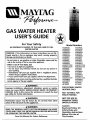
NLYFAG
GAS WATER HEATER
USER'S
For Your o,...GUIDE
a,eLy
AN ODORANT
IS ADDED TO THE GAS USED BY THIS
WATER HEATER
Model Numbers
HJ630NORT
HJ630NORT2
HJ640NORT
HJ630PORT
HJ630PORT2
HJ640PORT
WARNING: If the information in these instructions are not followed exactly, a fire or explosion may result, causing property
HJ640NORT2
HJ640NORS
HJ640NORS2
HJ640PORT2
HJ640PORS
HJ640PORS2
damage, persona injury or death.
HJ640NBRS
HJ640NOLS
HJ640NBRT
HJ640NBRTF
HJ640NBRT2
HJ640NOCT42W
HJ640NOCT52W
HJ650NKRT
HJ650NBRT
HJ650NBRT2
HJ650NRRT
HJ650NRRTF
HJ650NRRT2
HJ650NOCT32W
HJ640PBRS
HJ640POLS
HJ640PBRT
HJ640PBRTF
HJ640PBRT2
HJ640POCT42W
HJ640POCT52W
HJ650PKRT
HJ650PBRT
HJ650PBRT2
HJ650PRRT
HJ650PRRTF
HJ650PRRT2
HJ650POCT32W
HJ650NBRS2
HJ665NRRT5
H675NRRS
H675NRRT
HJ650PBRS2
HJ665PRRT5
H675PRRS
H675PRRT
-Do not store or use gasoline or other flammable vapors and liquids in the vicinity of this or any other appliance.
-WHAT TO DO IF YOU SMELL GAS
• Do not try to light any appliance.
• Do not touch any electrical switch; do not use any phone in
your building.
• Immediatelycall your gas supplierfrom a neighbor'sphone.
Follow the gas supplier's instructions.
• If you cannot reach your gas supplier, call the fire department.
-Installation and service must be performed by a qualified installer,
service agency or the gas supplier.
_,WARNING
Improper installation,
adjustment,
alteration,
service or maintenance can cause DEATH, SERIOUS BODILY INJURY, OR PROPERTY
FOR POTABLE WATER
HEATING ONLY
DAMAGE. Refer to this manual for assistance or consult the local
gas utility for further information.
NOT SUITABLE FOR
SPACE HEATING
AWARNING
NOT FOR USE IN
Flammable vapors may be drawn by air currents from other
areas of the structure to this appliance.
Caution:
Read and Follow
•,WARNING
READ THE GENERAL SAFETY SECTION BEGINNING ON INSIDE
COVER AND THEN THIS ENTIRE MANUAL BEFORE INSTALLING
OR OPERATING THIS WATER HEATER.
Save this Manual for Future
MANUFACTURED
(MOBILE) HOMES
Reference.
All
Safety Rules and
Operating
Instructions
Before First Use of
This Product.
Safety Instructions
•,WARNING
AWARNING
Improper installation, adjustment, alteration, service
or maintenance can cause DEATH, SERIOUS BODILY
INJURY, OR PROPERTY DAMAGE. Refer to this manual for assistance consult your local gas utility or call
Maytag Customer Service at %800-788-8899 for an
authorized servicer for further information,
At the time of manufacture this water heater was provided with a combination temperature-pressures relief
valve certified by a nationally recognized testing laboratory that maintains periodic inspection of production
of listed equipment or materials, as meeting the
requirements for Relief Valves and Automatic Gas
Shutoff Devices for Hot Water Supply Systems,and the
current edition of ANSI Z21.22 and the code requirements of ASME. If replaced, the valve must meet the
requirements of local codes, but not less than a combination temperature and pressure relief valve certified as
meeting the requirements for Relief Valves and
Automatic Gas Shutoff Devices for Hot Water Supply
Systems,ANSI Z21.22 by a nationally recognized testing
laboratory that maintains periodic inspection of production of listed equipment or materials.
The valve must be marked with a maximum set pressure not to exceed the marked hydrostatic working
pressure of the water heater (150 Ibs./sq. in.) and a discharge capacity not less than the water heater input
rate as shown on the model rating plate. (Electric
heaters - watts divided by 1000 x 3415 equal BTU/Hr.
rate.)
Your local jurisdictional authority, while mandating the
use of a temperature-pressure relief valve complying
with ANSI Z21.22 and ASME, may require a valve model
different from the one furnished with the water heater.
•,WARNING
WATER HEATERS EQUIPPED FOR ONE TYPE GAS
ONLY: This water heater is equipped for one type
gas only. Check the model rating plate near the gas
control valve for the correct gas. DO NOT USE THIS
WATER HEATER WITH ANY GAS OTHER THAN THE
ONE SHOWN ON THE MODEL RATING PLATE. Failure
to use the correct gas can cause problems which can
result in DEATH, SERIOUS BODILY INJURY, OR PROPERTY DAMAGE. If you have any questions or doubts
consult your gas supplier or local utility,
_WARNING
INSTALLATIONS IN AREAS WHERE FLAMMABLE LIQUIDS (VAPORS) ARE LIKELYTO BE PRESENTOR STORED
(GARAGES, STORAGE, AND UTILITY AREAS, ETC):
Flammable liquids (such as gasoline, solvents, propane
(LP) or butane, etc.J, all of which emit flammable
vapors, may be improperly stored or used in such
areas. The gas water heater pilot light or main burner
can ignite such vapors. The resulting flashback and fire
can cause death or serious burns to anyone in the
area, as well as property damage,
If installation in such areas is your only option, then
the installation must be accomplished in a way that
the pilot flame and main burner flame are elevated
from the floor at least 18 inches. While this may reduce
the chances of flammable vapors from a floor spill
being ignited, gasoline and other flammable substances should never be stored or used in the same
room or area containing a gas water heater or other
open flame or spark producing appliance,
NOTE: Flammable vapors may be drawn by air currents
from other areas of the structure to the appliance,
Compliance with such local requirements must be satislied by the installer or end user of the water heater
with a locally prescribed temperature-pressure relief
valve installed in the designated opening in the water
heater in place of the factory furnished valve.
For safe operation of the water heater, the relief valve
must not be removed from it's designated opening or
plugged.
The temperature-pressure relief valve must be installed
directly into the fitting of the water heater designated
for the relief valve. Position the valve downward and
provide tubing so that any discharge will exit only
within 6 inches above, or at any distance below the
structural floor. Be certain that no contact is made with
any live electrical part. The discharge opening must not
be blocked or reduced in size under any circumstances.
Excessivelength, over 30 feet, or use of more than four
elbows can cause restriction and reduce the discharge
capacity of the valve.
No valve or other obstruction is to be placed between
the relief valve and the tank. Do not connect tubing i
directly to discharge drain unless a 6' air gap is provided. To prevent bodily injury, hazard to life, or property
damage, the relief valve must be allowed to discharge
water in quantities should circumstancesdemand. If the
discharge pipe is not connected to a drain or other suitable means, the water flow may cause property dam-
AWARNING
If this water heater will be used in beauty shops,
barber shops, cleaning establishments, or self-sero
vice laundries with dry cleaning equipment, it is
imperative that the water heater or water heaters
be installed so that combustion and ventilation air
be taken from outside these areas. Refer to the
"Locating The New Water Heater" section of this
manual and also the current edition of the National
Fuel Gas Code, ANSI Z223.1, also referred to as NFPA
54 for specifics provided concerning air required,
_,WARNING
A fire can start if combustible materials such as
clothing, cleaning materials, or flammable liquids
are paced aga nst or next to the water heater.
age.
T e Discharge Pipe:
• Must notbe smaller in size than the outlet pipe size
of the valve, or have any reducing couplings or other
restrictions.
Must
plugc_edor
blocked.
Must not
be ofbematerial
listed
for hot water distribution.
,
• Must be installed so as to allow complete drainage of
both the temperature-pressure relief valve, and the
discharge pipe.
• Must terminate at an adequate drain.
I
2
• tank.
Must not have any valve between the relief valve and
Safety Instructions
_I_WARNING
A gas water heater cannot operate properly without
the correct amount of air for combustion. Do not
install in a confined area such a closet, unless you
provide air as shown in the "Locating The New
Water Heater" section. Never obstruct the flow of
ventilation air. If you have any doubts or questions
at all, call your gas company. Failure to provide the
proper amount of combustion air can result in a fire
or explosion and can cause DEATH, SERIOUS BODILY
INJURY, OR PROPERTY DAMAGE.
_WARNING
This water heater must not be installed directly on
carpeting. Carpeting must be protected by a metal
or wood panel beneath the appliance extending
beyond the full width and depth of the appliance by
at least 3 inches (76.2mm) in any direction, or if the
appliance is installed in an alcove or closet, the
entire floor must be covered by the panel. Failure to
heed this warning may result in a fire hazard.
AWARNING
AWARNING
VENT DAMPERS - Any vent damper, whether it is
operated thermally or otherwise must be removed if
its use inhibits proper drafting of the water heater.
Thermally Operated Vent Dampers: Gas-fired water
heaters having thermal efficiency in excess of 80%
may produce a relatively low flue gas temperature.
Such temperatures may not be high enough to properly open thermally operated vent dampers. This
would cause spillage of flue gases and may cause
carbon monoxide poisoning.
Vent dampers must bear evidence of certification as
complying with the current edition of American
National Standard ANSI Z21.68 (ANSI Z21.66 & 67,
respectively, cover electrically and mechanically actuated vent dampers). Before installation of any vent
damper, consult your local gas utility for further
information.
HOTTER WATER CAN SCALD: Water heaters are
intended to produce hot water. Water heated to a
temperature which will satisfy clothes washing, dish
washing, and other sanitizing needs can scald and
permanently injure ,you upon contact. Some people
are more likely to be permanently injured by hot
water than others. These include the elderly, children,
the infirm, or physically/mentally
handicapped. If
anyone using hot water in your home fits into one of
these c_roups or if there is a local code or state law
requiring a certain temperature water at the hot
water tap, then you must take special precautions. In
addition to using the lowest possible temperature
setting that satisfies your hot water needs, a means
such as a mixing valve, should be used at the hot
water taps used by these people or at the water
heater. Mixing valves are available at plumbing supply or hardware stores. Follow manufacturers instructions for installation of the valves. Before changing
the factory setting on the thermostat,
read the
"Temperature Regulation" section in this manual.
AWARNING
• The appliance and its individual shutoff valve must
be disconnected from the gas supply piping system
during any pressure testing of the gas system at
test pressures in excess ofl/2 pound per square
inch (3.5kPa).
• The appliance must be isolated from the gas supply piping system by closing its individual manual
shutoff valve during any pressure testing of the
gas supply piping system at test pressures equal or
less than 1/2 pound per square inch (3.5kPa).
_WARNING
Soot build-up indicates a problem that requires correction before further use, Turn "off" gas to water
heater and leave "off" until repairs are made,
because failure to correct the cause of the sooting
can
in a
fire or OR
explosion
causing
DEATH, SERIOUSresult
BODILY
INJURY,
PROPERTY
DAMAGE.
AWARNING
AWARNING
BEFORE LIGHTING [PROPANE (L.P.) GAS WATER
HEATERS]: Propane (L.P.) gas is heavier than air.
Should there be a leak in the system, the gas will settie near the ground. Basements, crawl spaces, skirted
areas under manufactured (mobile) homes (even
when ventilated), closets and areas below ground
level will serve as pockets for the accumulation of
this gas. Before attempting to light or relight the
water heater's pilot or turning on a nearby electrical
ight switch, be absolutely sure there is no accumu-
Chemical vapor corrosion of the flue and vent system may occur if air for combustion contains certain
chemical vapors. Spray can propellants, cleaning solvents, refrigerator and air conditioner refrigerants,
swimming pool chemicals, calcium and sodium chloride, waxes, bleach, and process chemicals are typical compounds which are potentially corrosive.
ated gas in the area. Search for odor of gas by sniffng at ground level in the vicinity of the appliance. If
_dor is detected, follow steps indicated at "For Your
Safety" on the cover page of this manual then leave
the premises.
AWARNING
Obstructed or deteriorated vent systems may present a serious health risk or asphyxiation.
3
Safety Instructions continued on page 4.
1
l
Safety Instructions
A, WARNING
&WARNING
The water heater with draft hood installed must be
properly vented to a chimney which terminates outdoors. Never operate the water heater unless it is
vented to the outdoors and has adequate air supply
to avoid risks of improper operation, explosion or
asphyxiation.
INSULATING JACKETS: When installing an external
water heater insulation jacket on a gas water heater:
• DO NOT cover the temperature-pressure relief valve.
• DO NOT put insulation over any part of the top of
the gas water heater.
• DO NOT put insulation over the gas control valve or
gas control valve/burner cover, or any access areas
to the burner.
• DO NOT let insulation around the gas water heater
to get within 8 inches of the floor (access for servicing the burner).
• DO NOT cover or remove operating instructions,
and safety related warning labels and materials
affixed to the water heater.
Failure to heed this will result in the possibility of a
fire or explosion.
=t WARNING
Minimum clearances between the water heater and
combustible construction are 1" at the sides and rear,
4" at the front, and 6" from the vent pipe. Clearance
from the top of the jacket is 18" on most models,
Note that a lesser dimension may be allowed on
some models. Refer to the label on the water heater
adjacent to the gas control valve for all clearances.
,& WARNING
A CAUTION
WATER HEATERS EVENTUALLY LEAK: Installation of
the water heater must be accomplished in such a
manner that if the tank or any connections should
leak, the flow of water will not cause damage to
the structure. For this reason, it is not advisable to
install the water heater in an attic or upper floor.
When such locations cannot be avoided, a suitable
drain pan should be installed under the water
heater. Drain pans are available at your local hardware store. Such a drain pan must be not greater
than 1_½inches deep, have a minimum length and
width of at least 2 inches greater than the water
heater dimensions and must be piped to an adequate drain. The pan must not restrict combustion
air flow. Under no circumstances is the manufacturer to be held liable for any water damage in con-
Flood damage to a water heater may not be readily
visible or immediately detectible. However, over a
period of time a flooded water heater will create
dangerous conditions which can cause DEATH, SERIOUS BODILY INJURY, OR PROPERTY DAMAGE.
Contact the Maytag dealer from whom the appliance was purchased or call Maytag Customer Service
at 1-800-788-8899
for an authorized servicer to
replace a flooded water heater. Do not attempt to
repair the unit! It must be replaced!
AWARNING
HYDROGEN GAS: Hydrogen gas can be produced in
a hot water system that has not been used for a
long period of time (generally two weeks or more).
Hydrogen gas is extremely flammable and explosive.
To prevent the possibility of injury under these conditions, we recommend the hot water faucet be
opened for several minutes at the kitchen sink
before any electrical appliances which are connected
to the hot water system are used (such as a dishwasher or washing machine). If hydrogen gas is present, there will probably be an unusual sound similar to air escaping through the pipe as the hot water
faucet is opened. There must be no smoking or open
flame near the faucet at the time it is open.
nection with this water heater.
4
Table of Contents
Safety Instructions ...................................................................................................................................
2-4
Table of Contents ......................................................................................................
.5
Customer Information ........................................................................................
6
Product Specifications .........................................................................................
7-9
Accessories
and Tools Needed ...............................................................................
10
Accessories .......................................................................................................................................................................
Tools ............................................................................................................................................................................
10
10
Instructions for Installation ...............................................................................
11-21
Removing the Old Water Heater. ....................................................................................................................................
Typical Installation ............................................................................................................................................................
Locating the New Water Heater ..................................................................................................................................
Combustion Air and Ventilation for Appliances in Unconfined Spaces .............................................................................
Combustion Air and Ventilation for Appliances in Confined Spaces ............................................................................
Water Piping ....................................................................................................................................................................
Temperature-Pressure Relief Valve ....................................................................................................................................
Filling the Water Heater .................................................................................................................................................
Venting. ....................................................................................................................................................................
Gas Piping ................................................................................................................................................................
Installation Checklist ........................................................................................................................................................
Temperature Regulation. ................................................................................................................................................
.11
12
13,14
14
14,15
16
17
18
18,19
19,20
.21
.24
Service and Maintenance ...................................................................................
25-27
Venting System Inspection. ............................................................................................................................................
Burner Inspection .........................................................................................................................................................
L.R Gas Control Valve and Burner Assembly Replacement Information .........................................................................
Burner Cleaning .........................................................................................................................................................
Draining .........................................................................................................................................................................
Anode Rod Inspection ..................................................................................................................................................
Temperature-Pressure Relief Valve Operation .................................................................................................................
Drain Valve Washer Replacement ...............................................................................................................................
Housekeeping ...........................................................................................................................................................
Service ..............................................................................................................................................................................
25
.25
.26
26
.26
.27
27
27
.27
27
Condensation ..............................................................................................................................................................
Smoke/Odor ............................................................................................................................................................
28
28
Thermal Expansion ....................................................................................................................................................
Strange Sounds. ........................................................................................................................................................
Operational Conditions .............................................................................................................................................
Smelly Water ................................................................................................................................................................
Air in Hot Water Faucets ...........................................................................................................................................
.28
.28
.29,30
29
.29
High Temperature Shut Off System ........................................................................................................................
Not Enough Hot Water ............................................................................................................................................
Water is too Hot ...................................................................................................................................................
.29
.29
.30
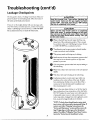
Leakage Checkpoints ...................................................................................................................................................
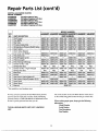
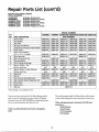
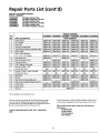
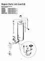
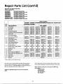
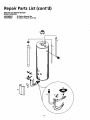
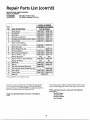
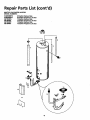
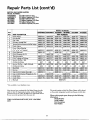
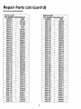
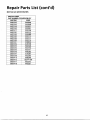
Repair Parts List
......................................................................................................................................
31
32-49
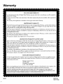
Warranty ......................................................................................................................
52
5
Customer Information
Thank You fo_ purchasing
a Maytag water heater.
Properly installed and maintained, it should give you years of
trouble free service. It is strongly suggested that this new water
heater be professionally installed, contact Maytag Customer
Service (1-800-788-8899) for recommended installers.
• The installation must conform with the instructions in this
manual; gas company rules; and Local Codes, or in the
absence of Local Codes, with the current edition of the
National Fuel Gas code, ANSI Z223.1, also referred to as
NFPA 54. This publication is available from your local
government or public library or gas company or by writing
NFPA, Batterymarch Park, Quincy, MA 02269.
• After reading this manual you have any questions or do not
understand any portion of the instructions, call Maytag
Customer Service at 1-800-788-8899 for an authorized
Abbreviations Found In This Instruction Manual
CSA - Canadian Standards Association
ANSI - American National Standards Institute
NFPA - National Fire Protection Association
services.
AWARNING
• Carefully plan the place where you are going to put the
water heater. Correct combustion, vent action, and vent
This gas-fired water heater is design certified by
CSA INTERNATIONAL
under American National
Standard/CSA Standard for Gas Water Heaters ANS
Z21.10.1 • CSA 4.1 (current edition). The installation
must conform with this manual, Local Codes and
with the current edition of the National Fuel Gas
Code, ANSI Z223.1.
This publication is available from your local govern-
pipe installation are very important in preventing death
from possible carbon monoxide poisoning and fires.
Examine the location to ensure the water heater compiles
with the "Locating the New Water Heater" section in this
manual.
• For California installatlon this water heater must be braced,
ment or public library, gas company, or by writing
NFPA, Batterymarch Park, Quincy, MA 02269.
anchored, or strapped to avoid falling or moving during an
• Read the "Safety Instructions" section, pages 2, 3 and 4 of
this manual first and then the entire manual carefully. If
you don't follow the safety rules, the water heater will not
dures. Instructions may be obtained from your local dealer,
wholesaler, public utilities or California Office of the State
Architect, 400 P Street, Sacramento, CA 95814.
earthquake. See instructions for correct installation proce-
operate properly. It could cause DEATH, SERIOUS
BODILY INJURY AND/OR PROPERTY DAMAGE.
• This manual contains instructions for the installation,
operation, and maintenance of the gas-fired water heater.
It also contains warnings through out the manual that you
must read and be aware of. All warnings and all instructions are essential to the proper operation of the water
heater and your safety. Since we cannot put everything on
the first few pages, READ THE ENTIRE MANUAL
BEFORE ATTEMPTING
TO INSTALL OR OPERATE THE WATER HEATER.
• Massachusetts
Code requires
this water heater
to be 2.00:
installed in accordance
with Massachusetts
248-CMR
State Plumbing Code and 248-CMR 5.00.
• Complies with SCAQMD rule #1121and districts havlng
equivalent NOx requirements.
6
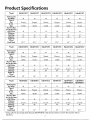
Product Specifications
*Model
Tank Capacity
In Gallons
HJ630NORT
HJ630PORT
HJ630NORT2
HJ630PORT2
HJ640NORT
HJ640PORT
30
30
30
30
40
40
Natural
Propane
Natural
Propane
Natural
Propane
Rate
Recovery Rate
In Gals Per Hour
@ 90°F Rise
Minimum
33_500
331500
33_500
33,500
38_000
35,500
34
34
34
34
39
36
Vent Pipe
Diameter
Height To
Top of
Draft Hood
3"
16"
3"
16"
3"
18"
3"
18"
3"
18"
3"
18"
59V2"
59%"
59V2"
591/2"
60"
60"
Type of
Gas
B.T.U.
*Model
Tank Capacity
In Gallons
HJ640NORT2
HJ640PORT2
HJ640NORS
HJ640PORS
HJ640NORS2
HJ640PORS2
40
40
40
40
40
40
Natural
Propane
Natural
Propane
Natural
Propane
Rate
Recovery Rate
In Gals Per Hour
@ 90°F Rise
Minimum
38_000
35,500
351000
351000
35_000
35_000
39
36
36
36
36
36
Vent Pipe
Diameter
3"
20"
3"
20"
3" or 4"
20"
3" or 4"
20"
3" or 4"
22"
3" or 4"
22"
Height To
Top of
Draft Hood
60"
60"
52"
52"
52"
52"
Type of
Gas
B.T.U.
*Model
HJ640NBRS
HJ640PBRS
HJ640NOLS
HJ640POLS
HJ640NBRT
HJ640NBRTF
HJ640PBRT
HJ640PBRTF
Tank Capacity
In Gallons
40
40
39
39
40
40
Type of
Gas
B.T.U.
Natural
Propane
Natural
Propane
Natural
Propane
Rate
Recovery Rate
In Gals Per Hour
@ 900F Rise
MinLmum
40,000
40,000
33_000
33_000
40_000
40,000
41
41
34
34
41
41
Vent Pipe
Diameter
3" or 4"
20"
3" or 4"
20"
3" or 4"
24"
3" or 4"
24"
3" or 4"
18"
3" or 4"
18"
Height To
Top of
Draft Hood
52"
52"
40"
40"
62V2"
62'/2"
Adding suffLx"D" denotes high altitude (Example HJ630NORTD).
than shown.
High altitude models have a B.T.U./Recovery Rate 10% iess
7
Product Specifications (cont'd)
*Model
HJ640NBRT2
HJ640PBRT2
HJ640NOCT42W
HJ640POCT42W HJ640NOCT52W
HJ640POCT52W
Tank Capacity
In Gallons
40
40
40
40
40
40
Gas
B.T.U.
Natural
Propane
Natural
Propane
Natural
Propane
Rate
Recovery Rate
In Gals Per Hour
@ 90*FRise
Minimum
401000
407000
40_000
401000
351000
351000
41
41
41
41
36
36
Vent Pipe
Diameter
3" or 4"
20"
3" or 4"
20"
3" or 4"
20"
3" or 4"
20"
3" or 4"
20"
Y' or 4"
20"
Height To
Topof
Draft Hood
62%"
62V2"
62V2"
62Vf'
65"
65"
*Model
HJ650NKRT
HJ650PKRT
Typeof
HJ650NBRT
HJ650PBRT
HJ650NBRT2
HJ650PBRT2
Tank Capacity
In Gallons
50
50
50
50
50
50
Type of
Gas
B .T.U.
Natural
Propane
Natural
Propane
Natural
Propane
Rate
Recovery Rate
In Gals Per Hour
@ 90°F Rise
Minimum
36,000
361000
40_000
40_000
40r000
40_000
36
36
41
41
41
41
Vent Pipe
Diameter
3"
20"
3"
20"
3" or 4"
20"
3" or 4"
20"
3" or 4"
22"
3" or 4"
22"
Height To
Top of
Draft Hood
60"
60"
63"
63"
63"
63"
'Model
HJ650NRRT
HI650NRRTF
HJ650PRRT
H|650PRRTF
HJ650NRRT2
HJ650PRRT2
50
50
50
50
50
50
Natural
Propane
Natural
Propane
Natural
Propane
Rate
Recovery Rate
In Gals Per Hour
@90*FRise
Minimum
52,500
527500
52,500
521500
361000
36_000
54
54
54
54
38
38
Vent Pipe
Diameter
4"
20"
4"
20"
4"
22"
4"
22"
3"
22"
3"
22"
Height To
Topof
Draft Hood
62W"
62%"
62V2"
62V2"
60_
60"
Tank Capacity
In Gallons
Type of
Gas
B.T.U.
Adding suffix "D" denotes high altitude (Example HJ630NORTD).
than shown.
HJ650NOCT32W
HJ650POCT32W
High altitude models have a B.T,U./Recovery Rate 10% less
8
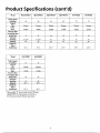
Product Specifications (cont'd)
*Model
HJ65ONBRS2
HJ65OPBRS2
HJ665NRRT5
HJ665PRRT5
H675NRRS
H675PRRS
Tank Capacity
In Gallons
50
50
65
65
73
73
Natural
Propane
Natural
Propane
Natural
Propane
Rate
Recovery Rate
In Gals Per Hour
@90°F Rise
Minimum
401000
401000
651000
551000
751000
551000
41
41
66
56
77
56
Vent Pipe
Diameter
3" or 4"
24"
3" or 4"
24"
4"
22"
4"
22"
4"
24"
4"
24"
Height To
Topof
Draft Hood
53%"
53%"
63%"
63%"
631/2"
62%"
*Model
H675NRRT
H675PRRT
Tank Capacity
In Gallons
75
75
Type of
Gas
B.T.u.
Natural
Propane
Rate
Recovery Rate
In Gals Per Hour
@90*F Rise
Minimum
75_100
75_100
79
79
Vent Pipe
Diameter
4"
26V4"
4"
26%"
Height To
Topof
Draft Hood
671/2''
67%"
Type of
Gas
B.T.U.
Adding suffix "D" denotes high altitude (Example
HJ630NORTD). High altitude models have a
B.T.U./Recovery Rate 10%less than shown.
9
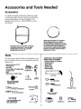
Accessoriesand Tools Needed
Accessories
To simplify the installation
Maytag
has available
the installa-
tion parts shown below. You may or may not need all of these
accessories
depending
Maytag Customer
rized installer.
on your type of installation.
Service at 1-800-788-8899
Call
for an autho-
DRAIN PANSAVAILABLEIN 22" DIAMETER
(PARTNUMBER66001011) FORWATER
HEATERSHAVING A DIAMETER20" OR LESS,
24" DIAMETER(PARTNUMBER66001105) FOR
WATERHEATERSHAVING A DIAMETERZZ_
OR LESSAND 2r DIAMETER(PARTNUMBER
66001012) FORWATERHEATERSHAVING A
DIAMETER26" OR LESS
EXPANSIONTANKSFORTHERMAL EXPANSION
CONDITIONSAVAILABLEIN Z GALLON(PART
NUMBER66001013) AND 5 GALLON(PART
NUMBER66001014) CAPACITY
Tools
You may or may not need all of these tools, depending
type of installation.
hardware
tools can be purchased
ADDITIONAL
on your
(2) 14"
_
Tin Snips
6 Foot Tape of Folding
Garden Hose
Drill
_
•
•
•
•
_t
_
Rule
TOOLS NEEDED
WHEN SWEAT SOLDERING
• Tubing Cutters or Hacksaw
• Propane Torch
at your local
store.
• Pipe Wrenches
• Screwdriver
•
•
•
•
These
Soft Solder
Solder Flux
Emery Cloth
Wire Brushes
GARDENHOSE
• Pipe dope or Teflon Tape
HACKSAW
6 FOOTTAPE
P,PE
WRENCH
ROLLOF TEFLONTAPE
(USEONLYON WATER
CONNECTIONS)
_SLOT-HEAD
3/4" WIRE BRUSH
1/2" WIRE BRUSH
SCREWDRIVER
_
PROPANETORCH
TIN SNIPS
PHILLIPSSCREWDRIVER
ROLLOF LEADFREE
SOFTSOLDER
PIPEDOPE(SQUEEZETUBE)
(USE FORWATERAND
GASCONNECTIONS)
ROLLOF EMERY
CLOTH
10
SOLDERFLUX
TUBING CUTTER
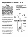
Instructions for Installation
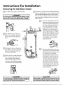
Removing the Old Water Heater
Turn "OFF" the gas supply to the water heater.
@
Disconnect the vent pipe from the draft hood where they
connect to the water heater. In most installations the vent
AWARNING
]
If the main gasline shutoffservingall gasappliancesis usefl,[
alsoshut "off" the gas at eachappliance.Leaveall gas appli-/
ancesshut"off" unti/the waterheaterinstallationiscomplete. J
pipe can be rifted off after any screw or other attached
devicesare removed. Dispose of the draft hood. The new
water heater has the draft hood which must be usedfor
proper operation.
a. If you have copper piping to the water
heater, the two copper water pipes can
four inches away from where they con
nect to the water heater. This will
@
@
@
__
@
Turn "OFF" the water to the water
avoid cutting offthe pipes too short.
Additional cuts can be made later if
necessary.
temperaturebe
cut withDisconnect
a hacksaw the
approximately
pressure relief valve drain line. When
heater. Some installations require that
the
heatertheisdrain
drained,
disconnect
the water
hose from
valve.
Close
the drain valve. The water heater is
the water be turned offto the entire
now completely disconnected and
house.
@
ready to be removed.
Check again to make sure the gas supply is "OFF" to the water heater. Then
disconnect the gas supply connection
from the gas control valve,
@
Attach a hose to the water heater drain
valve and put the other end in a floor
drain or outdoors. Open the water
heater drain valve. Open a nearby hot
water faucet which will relieve pressure
in the water heater and speed draining,
h. If you have galvanized pipe to the water
heater, loosen the two galvanized pipes
with a pipe wrench at the union in each
line. Also disconnect the piping
pieces should
remaining
to the
be saved
water since
heater.they
These
may
be needed when reconnecting the new
water heater. Disconnect the temperature-pressure relief valve drain line.
When the water heater is drained, disconnect the hose from the drain valve.
Close the drain valve. The water heater
:;2Z2°tTr122and
'vd2c°n
I
"WARN'"G
1
f
The water passingout_
maybe extremelyhot.I
Toavoidbeingscalded,makesureall connections
are tight and/
thatthe water flow isdirectedawayfrom anyperson,
j
ACAO"O"
1
[ Mineralbuildupor sedimentmay haveaccumulatedin the old[
] water heater.Thiscausesthe water heaterto be muchheavier|
11
[ than normalandthis residue,if spilledout,couldcausestaining.J
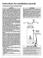
Instructions for Installation
(cont'd)
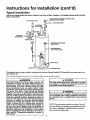
Typical Installation
CHECK ALL CONNECTIONS FOR LEAKS.CONSULTTHE LOCAL UTILITY COMPANY TO EXAMINE iNSTALLATION FOR PROPRIETYAND SAFETY.
VACUUMRELIEF
REQUIRED
BYSOMECODES
HOTWATEROUTLET
_
(REFER
TOLOCALCODES)
_
_TO
COLD
WATER
iNLET
CHIMNEY
WATTEEN_PEREDET
_
R_
*MIXINGVALVE
GAS
SUPPLY
,_
TEMPERATURE-PRESSURE
RELIEF
VALVE
DISCHARGE
PIPE
(Do not capor plug)
/ /
DRAINPAN
_
,-DRAIN VALVE
_
TO SUITABLE
DRAIN
This appliance has been design certified as complying with American National Standard/CSA Standard for water heaters and is consideredsuitable for:
Water (Potable) Heating: All models are "considered suitable for water (potable) heating."
AWARNING
[
HOTTER WATER CAN SCALD: Water heaters are
intended to produce hot water. Water heated to a
temperature
will sanitizing
satisfy clothes
dish washing, which
and other
needs washing,
can scald
ind permanently injure you upon contact. Some
}eople are more likely to be permanently injured by
tot water than others. These include the elderly,
children, the infirm, or physically/mentally
handicapped. If anyone using hot water in your home fits
into one of these groups or if there is a local code or
state law requiring a certain temperature water at
the hot water tap, then you must take special procautions. In addition to using the lowest possible
temperature settingthat
satisfies your hot water
needs, a means such as a mixing valve, should be
used at the hot water taps used by these people or
at the water heater. Mixing valves are available at
plumbing
supply or hardware
stores. of
Follow
manutacturers instructions
for installation
the valves.
A
WARNING
r
/This water heater shall not be connected to any heatling systems or component(s) previously used with a
ln°n'p°table water heating appliance.
[
A WARNING
t
/Toxic chemicals such as used for treatment of boilers
/or non-potable water heating appliances shall never
/be introduced into a potable water space heating
[system.
I
l
I
I
I
I
NOTE: To protect against untimely corrosion of hot and
coldwater fittings, it is strongly recommended that di-electric unions or couplings be installed on this water heater
Before changing the factory setting on the thermostar, read the "Temperature Regulation" section in
this manual.
when connected to copper pipe.
12
Instructions for Installation (cont'd)
Locating
Heater
the New Water
AWARNING
You should carefully" choose an indoor location for the new
This water heater must not be installed directly on
carpeting. Carpeting must be protected by a metal
or wood panel beneath the appliance extending
beyond the full width and depth of the appliance
by at least 3 inches (76.2mm) in any direction, or if
the appliance is installed in an alcove or closet, the
entire floor must be covered by the panel. Failure to
water heater, because the placement is a very important consideration for the safety of the occupants in the building and
for the most economical use of the appliance. This water
heater is not for usein manufactured (mobile) homes or outdoor installation,
heed this warning may result in a fire hazard.
Whether replacing an old water heater or putting the water
heater in a new location, the following critical points must be
observed.
a_, WARNING
The location selected should be indoors as close as practical to
Minimum
clearances
between
combustible
construction
arethe
1" water
at the heater
sides and
and i
rear, 4" at the front, and 6" from the vent pipe.
Clearance from the top of the jacket is 18" on most
models. Note that a lesser dimension
may be
allowed on some models. Refer to the label on the[
water heater adjacent to the gas control valve for
all clearances.
the gas vent or chimney to which the water heater vent is going
to be connected, and as centralized with the water piping system
as possible. The water heater, as all water heaters, will eventually
leak. Do not install without adequate drainage provisions where
water flow w_Ucausedamage,
A CAUTION
[
WATER HEATERS EVENTUALLY LEAK: Installation of
the water heater must be accomplished in such a
manner that if the tank or any connections should
leak, the flow of water will not cause damage to
the structure. For this reason, it is not advisable to
,2"HAX
--
_1"
_I"HIN.
_
VENTILATION
A,R O
OPENINGS
install the water heater in an attic or upper floor.
When such locations cannot be avoided, a suitable
drain pan should be installed
under the water
heater. Drain pans are available at your local hardware store. Such a drain pan must be not greater
than 1½ inches deep, have a minimum length and
,
oTOF_Ios_
"
W--I_,HIN
WITHOUT
DOOR T_V_ SET
_'.AX.
WITHDOOR
OFDOOR
KECTANGULAP,
3"
FRONTVIEW
width of at least 2 inches greater than the water
heater dimensions and must be piped to an adequate drain. The pan must not restrict combustion
air flow. Under no circumstances is the manufactur-
JJ
j Figure 1 I
I
I
I AI_DUCT
IJ
HIN.
/dEDUCT
_WARNING
er or Maytag to be held liable for any water damage in connection with this water heater.
A gas water heater cannot operate properly without the correct amount of air for combustion. Do
not install in a confined area such a closet, unless
Water
Heater"air section.
the The
flowNew
of
you provide
as shownNever
in theobstruct
"Locating
ventilation air. If you have any doubts or questions
at all, call your gas company. Failure to provide the
proper amount of combustion air can result in a fire
or explosion and can cause DEATH, SERIOUS BODILY INJURY, OR PROPERTY DAMAGE.
AWARNING
Propellants of aerosol sprays and volatile cornpounds, (cleaners, chlorine based chemicals, refrig- I
erants, etc.) in addition to being highly flammable I
in many cases, will also change to corrosive[
hydrochloric acid when exposed to the combustion
products of the water heater. The results can be
hazardous, and also cause product failure.
The location selection must provide adequate clearances for servicing and proper operation of the water heater.
13
Instructions for Installation (cont'd)
Locating the New Water
Heater (cont'd)
Combustion Air and Ventilation
for Appliances Located in
Unconfined Spaces
A WARNING
Unconfined
Space is a space whose volume is not less than
If this water heater will be used in beauty shops,
barber shops, cleaning establishments, or self-setvice laundries with dry cleaning equipment, it is
imperative
the combustion
water heaterand
or ventilation
water heaters
be installed that
so that
air
50 cubic feet per 1,000 Btu per hour of the aggregate input
rating ofaU appliancesinstalled in that space.Rooms com_
municating directlywith the space in which the appliances are
instaUed, through openings not furnished with doors, are
be taken from outside these areas. Refer to the
"Locating The New Water Heater" section of this
manual and also the current edition of the National
Fuel Gas Code, ANSI Z223.1, also referred to as NFPA
considered a part of the unconfined space
In unconfned spaces in buildings, infiltration may be adequate to provide air for combustion, ventilation and dilution
154 for specifics provided concerning air required,
of flue gases. However, in buildings of tight construction (for
example, weather stripping, heavily insulated, caulked, vapor
barrier, etc.), additional air may need to be provided using the
methods described in Combustion Air and Ventilation for
AWARNING
Appliances Located in Confined Spaces, b.
INSTALLATIONS IN AREAS WHERE FLAMMABLE LIQUIDS (VAPORS) ARE LIKELYTO BEPRESENTOR STORED
(GARAGES, STORAGE, AND UTILITY AREAS, ETC):
Flammable liquids (such as gasoline, solvents, propane
(LP) or butane, etc.), all of which emit flammable
vapors, may be improperly stored or used in such
areas. The gas water heater pilot light or main burner
Combustion Air and Ventilation
for ppuances Located in
,.
Confined C,,
Jpace
can ignite such vapors. The resulting flashback and fire
can cause death or serious burns to anyone in the
area, as well as property damage,
If installation in such areas is your only option, then
the installation must be accomplished in a way that
I the pilot flame and main burner flame are elevated
from the floor at least 18 inches. While this may
i reduce the chances of flammable vapors from a floor
spill being ignited, gasoline and other flammable substances should never be stored or used in the same
i room or area containing a gas water heater or other
open flame or spark producing appliance,
NOTE: Flammable vaporsmay be drawn by air currents
ifrom other areas of the structure to the appliance,
Confined Space is a space whose volume is less than 50 cubic
feet per 1,000 Bm per hour of the aggregate input rating of all
appliances installed in that space.
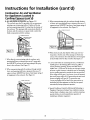
a. ALLAIR FROM INSIDE BUILDINGS:
(See Page 13 Figure 1, and Figure 2 below)
The confined space shall be provided with two permanent
openings communicating directly with an additional
room(s) of sufficient volume so that the combined volume
of all spaces meets the criteria for an unconfined space.
The total input of all gas utifization equipment installed in
the combined space shall be considered in making this
determination. Each opening shall have a minimum free
area of one square inch per 1,000 BTU per hour of the
total input rating of all gas utilization equipment in the
confined space, but not less than 100 square inches. One
opening shall commence within 12 inches of the top and
one commencing within 12 inches of the bottom of the
enclosure.
ENT
FURNACE
[ Figure 2 ]
!.
[
14
OPENINGS
i
r i i r i i r i i
r i L r i J r L
r i r t i i • _ r
I
r
Instructions for Installation (cont'd)
Combustion Air and Ventilation
for Appliances Located in
Confined Spaces (cont'd)
b. ALL AIR FROM OUTDOORS: (see Figures 3-5)
The confined sp_ce shall be provided with two permanent
openings, one commencing within 12 inches of the top
and one commencing within 12 inches from the bottom of
the enclosure. The openings shaU communicate directly, or
by ducts, with the outdoors or spaces (crawl or attic) that
freely communicate with the outdoors.
3. When communicating with the outdoors through horizontal ducts, each opening shall have a minimum free area of 1
square inch per 2,000 BTU per hour of total input rating of
all equipment in the enclosure. (See Figure 5.)
F_ure
[ Figure 3 I
5
4. When ducts are used, they sha]] be of the same cross-sectional area as the free area of the openings to which they
connect. The minimum short side dimension of rectanguiar
1. When directly communicating with the outdoors, each
opening shall have a minimum free area of 1 square inch
per 4,000 BTU per hour of total input rating of all equipment in the enclosure. (See Figure 3.)
air ducts shall not he less than 3 inches. (See Figure 5.)
5. Louvers and Grilles: In calculating free area, consideration
shall be given to the blocking effect of louvers, grilles or
screens protecting openings. Screens used shall not be
2. When communicating with the outdoors through vertical
ducts, each opening shall have a minimum free area of i
square inch per 4,000 BTU per hour of total input rating of
all equipment in the enclosure. (See Figure 4.)
smaller than % inch mesh. If the free area through a design
of louver or grille is known, it should be used in calculating
the size opening required to provide the free area specified.
If the design and free area is not known, it may be assumed
that wood louvers will be 20-25 percent free area and metal
louvers and grilles wiI1have 60-75 percent free area.
Louvers and grilles shall be fixed in the open position or
interlocked with the equipment so that they are opened
automatically during equipment operation.
6. Special Conditions Created by Mechanical Exhausting or
Fireplaces: Operation of exhaust fans, ventilation systems,
clothes dryers or fireplaces may create conditions requiring
-Figure
4
attention
]
avoid
special
to
unsatisfactory operation
installed gas utilization equipment.
15
of
Instructions for Installation (cont'd)
Water Piping
AWARNING
]
2. Look at the top cover oftbe water heater. The cold water
inlet is marked cold. Connect the cold water pipe to the
cold water inlet of the water heater.
]
HOTTER WATER CAN SCALD: Water heaters are [
intended to produce hot water. Water heated to a [
temperature
which will satisfy clothes washing, J
dish washing, and other sanitizing needs can scald [
and permanently injure you upon contact. Some I
people are more likely to be permanently
injured by [
hot water than others, These include the elderly, J
children, the infirm, or physically/mentally
handi- I
capped. If anyone using hot water in your home fits I
into one of these groups or if there is a local code or I
state law requiring a certain temperature water at [
the hot water t.a_, then you must take special pre- ]
cautions. In addition to usincj the lowest possible I
temperature setting that satisfies your hot water l
needs, a means such as a mixing valve, should be I
used at the hot water taps used by these people or
at the water heater. Mixing valves are available at
plumbing supply or hardware stores, Follow manufacturers instructions for installation of the valves.
Before changing the factory setting on the thermo-
NOTE: This water heater is superinsulated to minimize
heat loss from the tank. Further reduction in heat loss
canbeaccomplishedbyinsulatingthehotwaterlines
from the water heater.
SWEATCOUPLING
_
J
thisStat'
inmanual.
read the "Temperature
Regulation"
section
This water heater shall not be connected to any heating systems or component(s) used with a non-potable water heating
appliance.
lfa water heater is installed in a closed water supply system;
such as one having a back-flow preventer, check valve, water
meter with a check valve, etc.., in the cold water supply;
means shall be provided to control thermal expansion.
Contact the local utility or call Maytag Customer Service
Center at 1-800-788-8899 for an authorized installer on how
to control this situation.
SHUTOFF
VALVE
THREADED
TO
_
__"___'_'_
_
TO HOUSE
WATERLINE
II
HOTOUTLET
_
II
_
_
COLDINLET
3/4" THREADED-COUPLING
1" ON73
and75
GALLON
--
(_
314"THREADED
COUPLING
1"ON73
and75
GALLON
_
TEMPERATUREPRESSURE
RELIEF
NOTE: To protect against untimely corrosion of hot and
cold water fittings, it is strongly recommended that all-elec-
VALVE
tric unions or couplings be installed on this water heater
when connected to copper pipe.
_
_
DISCHARGE
PIPE
(Do not cap
or plug)
The illustration shows the attachment of the water piping to
the water heater. The water heater is equipped with 3/, inch
water connections for 30, 40, 50 and 65 gallon models and 1
_
_
inch water connections for 73 and 75 gallon models.
.
NOTE: Ifusing copper tubing, solder robing to an adapter
before attaching the adaptor to the cold water inlet connection.
.
A
i i
! [
Do
solder
the cold
supplyline
cold
waternotinlet.
It will
harmwater
the dip
tube and directly
damage tothethetank.
_
_d
u
/_
J
6" AIRGAP
FLOORDRAIN
1. Look at the top cover of the water heater. The water outlet
is marked hot. Connect the hot water pipe to the hot
water oudet on the water heater.
16
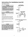
Instructions for Installation (cont'd)
Temperature-Pressure
Relief Valve
_WARNING
At thetime of manufacture
thiswater heaterwas provided with a combinationtemperature-pressures
reliefvalve
certifiedby a nationallyrecoclnized
testinglaboratorythat
maintains periodic inspectionof productionof listed
equipmentor materials,as meetingthe requirementsfor
ReliefValvesand AutomaticGasShutoff Devicesfor Hot
Water SupplySystems,and the currentedition of ANSI
Z21.22and the coderequirementsof ASME.If replaced,
the valvemustmeetthe requirements
of localcodes,but
not lessthan a combinationtemperatureand pressure
relief valve certified as meetingthe requirementsfor
ReliefValvesand AutomaticGasShutoffDevicesfor Hot
WaterSupplySystems,ANSIZ21.22by a nationallyrecognizedtestinglaboratorythat maintainsperiodicinspection
of productionof listedequipmentormaterials.
The valvemustbe markedwith a maximumset pressure
not to exceedthe markedhydrostatic
workingpressure
of
_,WARNING
I
The temperature-pressurerelief valve must be manually operated at least oncea year, Cautionshould be
taken to ensure that (1) no one is in front of or
around the outlet of the temperature-pressurerelief
valve dischargeline, and (2) the water manually dis- I
charged will not causeany bodily injury or property
damage becausethe water may be extremely hot.
If after manuallyoperating the valve, it fails to cornpletely reset and continuesto releasewater, immediately closethe cold water inlet to the water heater,
follow the draining instructions, and replace the
temperature-pressurerelief valve with a new one.
SHUTOFF
VALVE
thewater
heater(150Ibs./sq.
in.)anda discharge
capacity
not lessthanthewater
heaterinputrateasshownon
the
model
rating plate. (Electricheaterswatts dividedby
1000x 3415equalBTU/Hr.
rate.)
_-'_'_
_HOT F-_]11_
_l-_
_C:_
COLD
Your local jurisdictional
authority,
while mandating the
use of a temperature-pressure relief valve complying with
ANSIZ21.22and
ASME,may
requirea
valvemodeldifferent fromtheonefurnished
with
thewaterheater.
Compliance
with suchlocalrequirements
mustbe satisfied
by the installeror end userof the water heaterwith a
locally prescribedtemperature-pressure relief valve
installedin thedesignatedopeningin thewater heaterin
placeof thefactoryfurnishedva{ve.
Forsafeoperationof the water heater,the relief valve
,f
[ ,
,"x
_
|
_
plugged.mustn°tberem°ved
it's valve
designatedopening
or
The
temperature-pressurefrom
relief
must be installed
directly into the fitting of the water heater designated for
II1"_
the reliefvalve.Positionthevalvedownwardand provide
tubingsothat anydischargewill exitonlywithin6 inches
above,or at any distancebelow the structuralfloor.Be
certain that no contactis madewith any live electrical
part. The dischargeopening must not be blocked or
reducedin sizeunderanycircumstances.
Excessive
length,
over30 feet, or useof morethan four elbowscancause
restrictionand reducethedischarge
capacityof thevalve.
No valveorotherobstructionisto be placedbetweenthe
reliefvalveandthetank. Donotconnecttubingdirectlyto
dischargedrainunlessa 6" air gap isprovided.Toprevent
bodilyinjury,hazardto life,or propertydamage,the relief
valve mustbe allowed to dischargewater in quantities
shouldcircumstances
demand.If the dischargepipeisnot
connectedto a drainor othersuitablemeans,the water
flow maycausepropertydamage.
TheDischarge
Pipe:
• Mustnotbe smallerin sizethanthe outletpipesizeof
the valve, or have any reducing
restrictions,
Must not be plugged or blocked.
couplings
,orplug)
FLOOR
DRAIN
Y_
RELIEF VALVE
or other
OPENING
At
thetime of manufacture,
thiswaterheater
wasprovided
witha combination
temperature-pressure
reliefvalve
listedascomplying
withthestandard
forrelief
valves and automatic gas shut-off devices for hot water supply systems, ANSI
Z21.22. For safe operation of the water heater, the relief valve must not be
removed from its designated point of installation or plugged,
Your
local
urisdictional
authority,
whilemandating
theuse
ofatemperaturepressure
relief
valvecomplying
withANSI
Z21.22andASME,
mayrequire
avalve
both the temperature-pressure relief valve, and the discharge pipe.
model different from the one furnished with the water heate_
Compliance with such 10cal requirements must be satisfied by the installer or
end user of the water heater with a locally prescribed temperature-pressure
adequate drain,
• Must not have any valve between the relief valve and
terminate
RELIEFVALVE
DISCHARGE
cap PIPE
r_l
: Mustbe of materiallistedfor hot waterdistribution.
• Must be installedso asto allow completedrainageof
• Must
TEMPERATUREPRESSURE
I rl\
at an
relief
valveinstalled
opening
inthewaterheater.
See
manual
heading inthedesignated
J'Temperature-Pressure
Relief
Valves" for installation
maintenance of relief valve, discharge line, and other safety precautions.
tank.
17
and
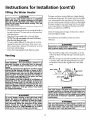
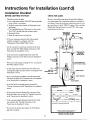
Instructions for Installation (cont'd)
Filling
the Water
Heater
A CAUTION
I
For proper venting in certain installations, a larger diameter
vent pipe may be necessary. Due to great variances in installations, unforeseeable by the manufacturer of the water heater,
you must consult your gas company to aid you in determining
the proper venting for your water heater from the vent tables
in the current edition of the National Fuel Gas Code ANSI
Never use this water heater unless it is completely
filled with water. Toprevent damage to the tank, I
the tank must be filledwith water. Water must flow I
from the hot water faucet before turning "ON" gas
to the water heater,
To fill the water heater with water:
•
•
Z223.1, also referred to as NFPA 54.
Close the water heater drain valve by turning the handle to
the right (clockwise). The drain valve is on the lower front
of the water heater,
Check the venting system for signs of obstruction or deterioration and replace if needed.
Open the cold water supply valve to the water heater.
NOTE: The cold water supply valve must be left open
when the water heater is in use.
The combustion and ventilation air flow must not be
obstructed.
• To insure complete fiUing of the tank, allow air to exit by
opening the nearest hot water faucet. Allow water to run
&WARNING
I
until a constant flow is obtained. This will let air out of the
water heater and the piping,
• Check all new water piping for leaks. Repair as needed.
Obstructed or deteriorated vent systems may present a serious health risk or asphyxiat on.
I
• Place the draft hood legs in the receiving holes on the top
Venting
of
thefit.
water heater. The legs will snap in the holes to give a
tight
• Place the vent pipe over the draft hood. With the vent pipe
in position, drill a small hole through both the vent pipe
and draft hood. Secure them together with a sheet metal
screw.
A WARNING
VENT DAMPERS - Any vent damper, whether it is
.operated thermally or otherwise must be removed
itits use inhibits proper drafting
of the water
heater.
Thermally Operated Vent Dampers: Gas-fired water
heaters having thermal efficiency in excess of 80%
may produce a relatively low flue gas temperature.
Such temperatures
may not be high enough to
properly open thermally operated vent dampers.
This wouldcause
spillage of flue gases and may
cause carbon monoxide poisoning.
Vent dampers must bear evidence of certification as
complying with the current edition of American
National Standard ANSI Z21.68 (ANSI Z21.66 & 67,
respectively, cover electrically and mechanically actuated vent dampers). Before installation of any vent
_damper, consult your local gas utility or local codes
for further information.
DRAFTHOOD _
VENT_J I
SCRE_WI_ I
_
__1_'
DRAFT
_
O_
DRAFTHOOD
_- _
,
L VENTTOOUTDOORS
OR
CHIMNEY
_OOD._
_,
AWARNING
The water heater with draft hood installed must be
_roperly vented to a chimney which terminates outDOTS.Never operate the water heater unless it is
vented to the outdoors and has adequate air supply
to avoid r sks of improper operation, explosion or
asphyxiation.
AWARNING
To insure proper venting of this gas-fired water
heater, the correct vent pipe diameter must be utilized. Any additions or deletions of other gas appliances on a common vent with this water heater
_WARNING
i
I
may adversely affect the operation of the water
heater. Consult the local gas utility or call Maytag
Customer Service at 1-800-788-8899 for an autho-
The vent pipe from the water heater must be no I
less than the diameter of the draft hood outlet on
the water heater, and must slope upward to the
rized servicer if any such changes are planned,
chimney at least ¼ inch per linear foot.
18
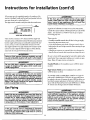
Instructions for Installation (cont'd)
AWARNING
All vent gases must be completely vented to the outdoors of the
stmcmre(dwelling). Install only the draft hood providedwith the
new water heaterand no other draft hood.
Vent pipes must be secured at each joint with sheet metal screws,
--
..
If the
ances
ance.
water
TO
main gas line shutoff serving all gas appliis used, also turn "OFF" the gas at each appliLeave all gas appliances
shut off until the
heater installation is complete.
I
I
CHIMNEY
A gas line of sufficient size must be run to the water heater.
,
PERLINEAR
FOOT ]
I
VENT PIPEINSTALLATION
Consult
of National
Code ANSI
Z223.1, the
also current
referred edition
to as NFPA
54 andFuel
the Gas
gas company
concerning pipe size.
There must be a minimum of 6" clearance between single wall
There must be:
vent pipe and any combustible material. Fill and seal any clearance
between single wall vent pipe and combustible material with mottar mix, cement, or other noncombustible substance. For other
• A readily accessible manual shut offvalve in the gas supply
line serving the water heater, and
• A drip leg (sediment trap) ahead of the gas control valve to
than single wall, follow vent pipe manufacturer's clearance specifi-
help prevent dirt and foreign materials from entering the gas
cations. To insure a fight fit of the vent pipe in a brick chimney,
seal around the vent pipe with mortar mix cement.
control valve.
• A flexible gas connector or a ground joint union between the
shutoff valve and control valve m permit servicing of the unit.
AWARNING
Failure to have required clearances between vent piping and combust b e mater a w
Be sure to check all the gas piping for leaks before lighting the
resu t n a f re hazard,
water heater. Use a soapy water solution, not a match or open
flame. Rinse off soapy solution and wipe dry.
AWARNING
Be sure vent pipe is properly connected to prevent ]
escape of dangerous flue gases which could cause I
deadly asphyxiation.
]
StandardModeis
sealevel.
are for installation up to 3,300 feet above
High Altitude Models are for installation from 3,300 to
5,500 feet above sea level.
AWARNING
Chemical vapor corrosion of the flue and vent system
may occur if air for combustion contains certain chemical vapors. Spray can propellants, cleaning solvents, I
refrigerator and air conditioner refrigerants, swimming
poo/chemicals, calcium and sodium chloride, waxes,
bleach, and process chemicals are typical compounds
which are potentially corrosive.
J
Ira standard model is installed above 3,300 feet or a high altirode model is installed above 5,500 feet, the input rating must
be reduced at the rate of 4 percent for each 1,000 feet above sea
level which requires replacement of the burner orifice in accordance with the National Fuel Gas Code ANSI Z223.1 / NFPA
54. Contact your local gas utility for further information.
Gas Piping
AWARNING
AWARNING
Failure to replace the orifice could result in improper
and inefficient operation of the appliance, producing carbon monoxide gas in excess of safe limits,
which could result in serious injury or death.
Contact your gas supplier for any specific changes
which may be required in your area.
Make sure the gas supplied is the same type listed on
the model rating plate. The inlet gas pressure must not
exceed 10.5 in. water column (2.6kPa) for natural gas
or 13 in. water column (3.2kPa) for propane (L.R) gas.
The minimum inlet gas pressure listed on the model
rating plate isfor the purpose of input adjustment.
AWARNING
If
the
gas
control
is subjected
to pressures
exceeding _½pound valve
per square
inch (3.5kPa),
the dam- II
age to the gas control valve could result in a fire or
exp osion from eaking gas.
The appliance and AWARNING
its gas connection must be leak I
tested before placing the appliance in operation.
19
Instructions for Installation (cont'd)
Gas Piping
(cont'd)
_,WARNING
GAS PIPING WITH
FLEXIBLE CONNECTOR
• The appliance and its individual shutoff valve
must be disconnected from the gas supply piping
system during any pressure testing of the gas system at test pressures in excess of 1/2 pound per
square inch (3.5kPa).
• The appliance must be isolated from the gas supply piping system by closing its individual manual
shutoff valve during any pressure testing of the
gas supply piping system at test pressures equal
or less than 1/2 pound per square inch (3.5kPa).
GASSUPPLY
PIPING
CI
i_1
MANUAL
SHUTOFF
VALVE
FLEXIBLE GAS CONNECTOR
AWARNING
Use pipe joint compound or teflon tape marked as
being resistant to the action of petroleum [Propane I
(L.R)]gases.
SEDIMENT
WITH ANSI
STANDARDS
LABELED
ASCOMPLYING
GROUNDJOINT
I
(OPTIONAL)
UNION
TRAP
A sediment trap shall be installed as close to the inlet of the
water heater as practical at the time of water heater instaUation. The sediment trap shall be either a tee fitting with a
capped nipple in the bottom outlet or other device recognized
as an effective sediment trap. Ira tee fitting is used, it shall be
installed in conformance with one of the methods of installation shown.
3" MIN.
TRAP)
GAS
CONTROL
VALVE
CAP
GAS PIPING
Connecting the gas piping to the gas control valve of the
water heater can be accomplished by either of the two methods shown.
WITH ALL BLACK IRON
GAS CONTROL
PIPE TO
GASSUPPLY
PIPING
_IWARNING
SHUTOFF
Contaminants in the gas lines may cause improper
operation of the gas control valve that may result
in fire or explosion. Before attaching the gas line
be sure that all gas pipe is clean on the inside. To
trap any dirt or toreign material in the gas suppl_(
line, a drip leg (sometimes called a sediment trap)
must be incorporated in the piping, The drip leg
must be readily accessible, Install in accordance
VALVE
MANUAL
_
GROUNDJOINT
UNION
edition of the National Fuel Gas Code, ANSI Z223.1
also referred to as NFPA 54.
with the "Gas Piping" section. Refer to the current
8LACKPIPE]_
_3" MIN.
2O
DRIP LEG
(SEDIMENT
TRAP)
L_JCJ
CONTROL
VALVE
GAS
Instructions for Installation (cont'd)
Installation
BEFORE
LIGHTING
Checklist
THE PILOT:
CHECK
FOR LEAKS
Check the gas lines for leaks.
Be sure to check all your gas pipes for leaks before lighting
a. Use a soapy water solution. DO NOT test for gas leaks
using a match or open flame,
b. Brush the soapy water solution on all gas pipes, joints
and fittings,
your water heater. Use a soapy water solution, not a match or
open flame. Check the factory gas fittings after pilot is lit and
gas control knob is still in "PILOT" position. Then, check the
fittings when the main burner is turned "ON". Use a soapy
c. Check for bubbling soap. This means you have a Ieak.
Turn "OFF" gas and make the necessary repairs.
d. Recheck for leaks.
water solution for this, too.
VENTPIPE
TO SHUTOFF
OUTDOORS
VALVE
e. Rinse off soapy solution and wipe dry.
OR
HIMNEY-/'_
_
_
4__.
installed and piped to an adequate drain? See
"Temperature-Pressure
Relief Valve" section.
1
Are the cold and hot water lines connected to the water
IS
the new
temperature-pressure
reliefinstructions
valve properly
heater
correctly?
See "Water Piping"
in the
_OT_
)CO_
GAS
SUPPLY
"Instructions for Installation" section.
cOLD
DRAFTHOOD(_
Is the water heater completely fdled with water? See
"Filling" instructions in the "Instructions for Installation"
TEMPERATURE-PRESS
RELIEF
VALVE
_
SHUTOFF
VALVE
section.
Will a water leak damageanything? Seethe "Locating the
New Water Heater" section.
-- DISCHARGE
PIPE
(Do notcapor plug)
TEE
Is there proper clearance between the water heater and
anything that might catch fire? See the "Locating the New
_
DRIPLEG_
(Sedimenttrap)
/
PIPECAP_
water Heater" section.
DRAINVALVE
r_
Do you
haveproperly?
adequate See
ventilation
so thatAir
theand
water
heater
will
operate
"Combustion
Ventilation"
in the "Instructions for Installation" section.
_
6 INCHAIRGAP
FLOORDRAIN
Is the draft hood vent piping properly secured? See
"Venting" instructions in the "Instructions for Installation"
section.
HEATING
Is there proper clearance between the vent pipe and anything that might catch on fire? See "Venting" instructions
in the "Instructions for Installation" section.
'_gg_
(POTABLE)
ONLY
,_
[[[[_]_,,,
._,.,
MAXlMU_HYDRC_TAT_C
Is the vent pipe properly sloped and does the vent terminate outdoors? See "Venting" instructions in the
Instructions for Installation section.
_.o, ,_,
GASP'_E_SJJF_E
_PS
wc
1_0
....
_
AUTOMATIC
STORAGE
WATER
HEATER
DO yOUneed to call your gas company to check the gas
pipe and its hookup?
Maytag®isaTrademarkofMayta
is uteri _x_der [,i_ea_
Corporafionand
_o State _d_lrles,
I_c
MODEL RATING PLATE
21
Instructions for Operation
Lighting
AWARNING
__
BEFORE LIGHTING [PROPANE (L.P.) GAS WATER
HEATERS]: Propane (L.P.) gas is heavier than air.
Should there be a leak in the system, the gas will
settle near the ground. Basements, crawl spaces,
skirted areas under manufactured (mobile) homes
(even when ventilated), closets and areas below
ground level will serve as pockets for the accumulation of this gas. Before attempting to light or relight
the water heater's pilot or turning on a nearby electrical light switch, be absolutely sure there is no
accumulated gas in the area. Search for odor of gas
by sniffing at ground level in the vicinity of the
appliance. If odor is detected, follow steps indicated
at "For Your Safety" on the cover page of this man-
[
1
L Figure 6 J
ual then leave the premises.
Lighting and operating instructions are located on front of
the water heater, above or to one side of the gas control valve.
[ Figure 7 ]
AWARNING
AN ODORANT IS ADDED TO THE GAS USED
FOR YOUR SAFETY
IF YOU SMELL GAS:
THIS
WATER
HEATER.
• Do not try toBY
light
any
appliance.
• Do not touch any electrical switch; do not use any
phone in your building.
• Immediately call your gas supplier from a neighbor's phone. Follow the gas supplier's instructions.
• If you cannot reach your gas supplier, call the fire
department.
_
[ Figure8 ]
.AWARNING
DO NOT force the gas control knob. Use only your
hand to push it down to light the pilot, or to turn it
to "ON", "OFF" or "PILOT". Never use a tool such as
a lever, wrench or pliers. Do not hit or damage the
knob. A damaged knob may result in an explosion
and serious
If you have
problem turning the
knob,
call theinjury.
gas supplier
immediately.
_J
L.,_
INNERDOOR
r ............
..!....
OUTERDOOR
[ Figure 9 ]
22
OUTERDOOR
75 GALLON
Instructions for Operation (cont'd)
Lighting
label on the water
heater
FOR YOUR SAFETY
as it appears
above the thermostat
READ BEFORE
LIGHTING
WARNING
If you do not follow these instructions exactly, a fire or explosion
may result causing property damage, personal injury or loss of life.
A. This appliancehasa pilot which mustbe lighted by
• If youcannotreachyourgassupplier,callthe fire
hand.Whenlighting
thepilot,followtheseinstructions
department.
exactly.
C.Useonlyyourhandto pushin orturnthegascontrol
B.BEFORE
LIGHTING
smellallaroundtheappliance
area
knob.Neverusetools.Iftheknobwillnotpushin or
for gas.Be sureto smellnextto thefloorbecause
turnbyhand,don'ttryto repairit,carla qualified
setsomegasisheavier
thanairandwillsettleonthefloor,
vicetechnician.
Forceorattempted
repairmayresult
WHATTODOIFYOUSMELLGAS
inafireorexplosion.
• Donottrytolightanyappliance.
D.Donotusethisappliance
ifanyparthasbeenunder
• Do nottouchanyelectricswitch;do notuseany
water.Immediately
calla qualified
servicetechnician
phoneinyourbuilding,
toinspect
theappliance
andto replace
anypartofthe
• Immediately
callyourgassupplierfroma neighbor's
controlsystemandanygascontrolwhichhasbeen
phone.Followthegassupplier's
instructions,
underwater.
LIGHTING
INSTRUCTIONS
1. STOP!Readthesafetyinformation
aboveonthislabel.
2, Remove
outerdoor.
:_
3. Setthethermostatto lowestsettingby _
9. Pushin controlknoball theway andholddown.
Immediately
lightthepilotwitha match.Continue
to
holdcontre[knobinfor aboutone(1)minuteafterthe
wise,(f _) to its lowesttemperature
setting
(with
ondial)asshown.
DO _
turning
thee
warrow
atertemperature
dialclock-
shouldremainlit. If it goesout, repeatsteps3
through
8.
pilotis lit.Release
knobanditwillpopbackup.Pilot
@) to "OFF"posi4. NOTFORCE,
Turngascontrolknobclockwise
tion.Knobcannotbeturnedfrom"PILOT"to "OFF"
• If
knobdoesnot
popupwhenreleased,
stopand
immediately
callyour
servicetechnician
orgassupplier.
Ifthepilotwillnotstaylitafterseveraltries,depress
(Figure6,page22)
knobisdepressed
slightly.DO NOTFORCE.
5. unless
Waitfive(5)minutes
to clearoutanygas.If
youthen
smellgas,STOP!Follow"B" inthesafetyinformation
aboveonthis[abe[.Ifyoudon'tsmellgas,gotothe
nextstep.
6. Remove(oropen)innerdoorlocatedbelowthe gas
controlunit.
7. Findpilot-follow
metaltubefromgascontrol.
Thepilot
is locatedin frontof theburnerorontherightsideof
theburner.
.n_
• andturnthegascontrolknobclockwise_
to
"OFF"andcallyourservicetechnician
orgassuppiier.(Figore
6,pe_ja22)
10.Replace
(orclose)innerdoor.(Figure
9,page22)
11.Atarmslengthaway,turngascontrolknobcounterclockwise
'{O to thefull "ON"position.
Warning
do not use gas control knob to regulate gas
flow. (Figure
8,page22)
BURNER
ting.Themark(away,
• ) indicative
ofapproximate
120°F
is
PILOT
setthethermostat
todesired
set*TherTnocouple 12.Atarmslength
preferred
startingpoint.
Somelocallawsmayrequire
8. If you don'tsmell_s, turn knobon gas control
a lowerstartingpoint.If hotterwateris desired,see
counte_ciockwise_m(_to
PILOTposition.
(FigureT,
instruction
manualand"warning"below.
page22)
13.Closetheouterdoor,
BURNER/b,_
PILOT /r_l*
or
_
WARNING
Hotterwaterincreasesthe risk of scaldinjury. Beforechangingtemperature
settingseeinstructionmanual.
TO TURN
OFF GAS TO APPLIANCE
1.Setthethermostatto lowestsettingbyturningthe
watertemperature
dialclockwise(Y_"_) to its lowest
temperature
setting(witharrowondial)asshown.DO
NOTFORCE.
2. Turngascontrolknobclockwise_ _ to "OFF"
position.Knobcannotbe turnedfrom"PILOT"to
"OFF" unlessknobis depressed
slightly.DO NOT
FORCE.
3.Closeouterdoor.
23
Instructions for Operation (cont'd)
Temperature
Regulation
Due to the nature of the typical gas water heater, the water
temperature in certain situations may vary up to 30°F higher or
lower at the point of use such as, bathtubs, showers, sink, etc.
Turn the water temperature dial clockwise (("-'_)
to
decrease the temperature, or counterclockwise (¢"'_)
to
increase the temperature.
r_/'-GAS
This means that when the temperature adjustment dial is set
at the mark approximating 120 ° F, the actual water temperature at any hot water tap could be as high as 150°F or as low
as 90°E
O
Any water heater's intended purpose is to heat water. Hot
water is needed for cleaning (bodies, dishes, clothing). Hot
water will present a scald hazard. Depending on the time element, and the people involved (normal adults, children, toddlers, elderly, infirm, etc.) scalding may occur at different
temperatures.
r'
k
_'_
_
_.
(_)
TER
_, WARNING
PILOT LIGHTING
- Set here before attempting to light
pilot.
Temperature Setting
VERY HOT =
C=
B=
A=
• =
Time to Produce 2nd & 3rd
De_reeBurnsonAdultSIdn
approx. 160°F
approx.150°F
approx. 14001;`
approx. 130017
approx.120°F
LOW = approx.80°F
About 1/2 second
About 1-1/2 seconds
Less than 5 seconds
About 30 seconds
More than5 minutes
...........
NOTE: Water temperature range of I20*F-140°F recommended by most dlshwasher manufacturers.
AWARNING
ply or for
hardware
stores.
manufacturers
instructions
installation
of Follow
the valves.
Before changing
the factory setting on the thermostat,
read the
"Temperature Regulation" section in this manual.
Should overheating occur or the gas supply fail to
I shut off, turn "OFF" the manual gas control valve to
[ the appliance.
1
ever allow small children to use a hot water tap, /
r to draw their own bath water. Never leave a /
lid or handicapped person unattended in a bath-|
ub or shower.
O
TEMPERATURE
(ADJUSTING OIAL)
HOTTER WATER CAN SCALD: Water heaters are
intended to produce hot water. Water heated to a
temperature which will satisfy clothes washing, dish
washing, and other sanitizing needs can scald and
permanently injure you upon contact. Some people
are more likely to be permanently injured by hot
water than others. These include the elderly, children,
the infirm, or physically/mentally
handicapped. If
anyone using hot water in your home fits into one of
these _roups or if there is a local code or state law
requermg a certain temperature water at the hot
water tap, then you must take special precautions. In
addition to using the lowest possible temperature
setting that satisfies your hot water needs, a means
such as a mixing valve, should be used at the hot
water taps used by these people or at the water
heater. Mixing valves are available at plumbing sup-
AWAR.,NG
KNoBCONTROL
[
The thermostat of this water heater has been factory set at its
lowest position, to reduce the risk of scald injury. It is
adjustable and must be reset to the desired temperature setting. The mark (k) indicative of approximately 120°F is the
preferred starting point. Some states have a requirement for a
lower setting. If you need hotter water, follow directions for
temperature adjustment, but beware of the warnings in this
section.
24
]
Service and Maintenance
Venting
System
Inspection
Burner
At least once a year a visual inspection should be made of the
venting
system.
Inspection
r
AWARNING
Youshou|d lookfor:
/ Flooddamageto a_may
• Obstructions which could cause improper venting. The
combustion and ventilation air flow must not be obstructed,
not be readily
] visible or immediately detectible. However, over a
period of time a flooded water heater will create
dangerous conditions which can cause DEATH, SERIOUS BODILY INJURY, OR PROPERTY DAMAGE.
Contact the Maytag dealer from whom the appliance was purchased or call Maytag Customer Service
at 1-800-788-8899
for an authorized servicer to
replace a flooded water heater. Do not attempt to
repair the unit! It must be replaced!
• Damage or deterioration which could cause improper venting or leakage of combustion products,
• Rusted flakes around top of water heater,
At least once a year a visual inspection should be made of the
main burner and pilot burner. The drawing is for your reference.
_WARNING
Chemical vapor corrosion of the flue and vent system may occur if air for combustion contains certain
chemical vapors. Spray can propellants, cleaning solvents, refrigerator and air conditioner refrigerants,
swimming pool chemicals, calcium and sodium chloride, waxes, bleach, and process chemicals are typi-
You should check for sooting which is not normal and will
impair proper combustion.
[ ca compounds which are potentially corrosive.
Obstructed or deteriorated
vent systems may pre-
sent a serous hemth r sk or asphyxiat on.
AWARNING
__
NATURAL
AWARNING
OR PROPANE
33,000
TO 52,500
(L.R) GAS BURNER
BTUH
INPUT
Be sure the vent piping is properly connected to
prevent escape of dangerous flue gasses which
coudcausedeadyasphyxaton.
- /_
_'_-/_
AWARNING
If after inspection of the vent system you found
sooting or deterioration, something is wrong. Call
the local gas utility or Maytag Customer Service at
1-800-788-8899 for an authorized servicer to correct
the problem and clean or replace the flue and venting before resuming operation of the water heater.
Failure to make corrections can result in a fire, or
explosion causing DEATH, SERIOUS BODILY INJURY,
OR PROPERTY DAMAGE.
NATURAL
ORPROPANE
(L.R)GASBURNER
s5,000TO 75,000BTUHINPUT
NATURAL
OR PROPANE (L.P.) GAS BURNER
75,100 BTUH INPUT
AWARNING
Soot build-up indicates a problem that requires correction before further use. Turn "OFF" gas to water
heater and leave "OFF" until repairs are made,
because failure to correct the cause of the sooting
can result in a fire or explosion causing DEATH,
SERIOUS BODILY INJURY, OR PROPERTY DAMAGE.
25
Service and Maintenance (cont'd)
L.RGas Control Valve & Burner
Assembly Replacement
Burner Cleaning
Information
In the event your burner needs cleaning, use the followlng
A, WARNING
instructions:
PROPANE (L.P.) GAS CONTROL VALVE AN BURNER
ASSEMBLY REPLACEMENT INFORMATION.
If inspection o/the burner shows that cleaning is required,
For Propane (L.R) Gas Models Only:
turn the gas control knob clockwise (f'-_
Your water heater is equipped with a Propane (L,R)
gas control valve and a main burner assembly with
left hand threads for the following fittings and their
connections.
position, depressing slightly.
to the "OFF"
NOTE: The knob cannot be turned from "PILOT"
"OFF" unless knob is depressed slightly. DO NOT
FORCE.
• The connection between the manifold and the gas control vaive
(A to B) are left hand threads.
to
Loose deposits on or around the burner can be removed by
carefiflly using the hose of a vacuum cleaner inserted through
• The connection between the main burner orifice and the manl-
the access door of the water heater. If the burner needs to be
fold (C to D) are left hand threads,
removed for additional cleaning, call Maytag Customer
Service at 1-800-788-8899 for an authorized servicer to
For ordering these replacement parts, please refer to the "Repair
Parts List" section of this manual,
remove and clean the burner and correct the problem that
required the burner to be cleaned.
The water heater should be drained if being shut down during
freezing temperatures. Also periodic draining and cleaning of
sediment from the tank may be necessary_
Draining
A_
_
• Turn the gas control knob to the "OFF" position.
• CLOSE the cold water inlet valve to the water heater.
• OPEN a nearby hot water faucet and leave open to allow
c_
for draining.
• Connect a hose to the drain valve and terminate to an adequate drain,
• OPEN the water heater drain valve to allow for tank
draining.
NOTE: If the water heater is going to be shut down and
drained for an extended period, the drain valve should be
left open with hose connected allowing water to terminate
to an adequate drain.
• Close the drain valve.
• Follow instructions in the "Filling The Water Heater"
section.
• Follow the lighting instructions in the "Lighting" section to
restart the water heater.
26
Service and Maintenance (cont'd)
Anode Rod Inspection
The rod must be maintained to keep the tank in operating
Drain Valve Washer
Replacement
condition. Anode deterioration depends on water conductivity,
NOTE.
not necessarily water condition. It may be necessary to have
the anode rod inspected a few times during the first year to see
what effect the water has had. A corroded or pitted anode rod,
available at your nearest hardware store. For ordering
replacement washers, refer to the "Repair Parts List" section.
in the first year, indicates high water conductivity and should
be checked and or replaced more often than an anode rod that
appears to be fairly clean. Inspection should be conducted by a
qualified technician,
1. Turn "OFF" gas supply to water heater.
2. Follow "Draining" instructions.
3, Turning counter clockwise, remove the hex cap below the
screw handle.
For replacement, use a 1%2' x *Y_'x Ys'thick washer
4, Remove the washer and put the new one in place.
Tem perature-Pressure
Valve Operation
The temperature-pressure
ated at least once a year.
Relief
5, valve
Screwand
the retighten
handle and
using
cap aassembly
wrench. DO
back NOT
into the
OVER
drain
TIGHTEN.
6. Follow instructions in the "Filling The Water Heater"
section.
7. Check for leaks.
8. Follow the lighting instructions in the "Instructions for
Operation" section to restart the water heater.
relief valve must be manually oper-
TEMPERATURE-PRESSURE
CAPASSEMBD/
_"
_'_WASHER
HANDLE
AND
PIPE
Failure to install DISCHARGE
and maintain
a new properly listed temperature-pressure relief valve will release the manufacturer from
(_
•
HouseReeping
any claim which might result from excessive temperature or
pressure.
Vacuum around base of water heater for dust, dirt, and lint on
WARNING
If the temperature-pressure
relief
valve
a regular basis,
Combustible materials such as clothing, cleaning materials, or
on the
appliance weeps or discharges periodically, this
may be due to thermal expansion• Your water
heater may have a check valve installed in the
water line or a water meter with a check valve. Call
Maytacj Customer Service at 1-800-788-8899 for an
authorized servicer for further information. Do not
plug the temperature-pressure relief valve,
flammable liquids, etc, must not be placed against or adjacent
to the water heater.
To insure sufficient ventilation and combustion air supply,
proper clearances from the water heater must be maintained
at all times.
Service
AWARNING
When checking the temperature-pressure relief valve
operation, make sure that (1) no one is in front of or
around the outlet of the temperature-pressure relief
valve discharge line, and (2) that the water manually
discharged will not cause any property damage
Before calling for repair seTvice,read the Start
Up
Conditions
and Operational Conditions found in the Troubleshooting
Guide of this manual.
because the water may be extremely hot.
If after manually operating the valve, it fails to completely reset and continues to release water, immediately close the cold water inlet to the water heater,
follow the draining instructions, and replace the
temperature-pressure relief valve with a new one,
If a condition persists or you are uncertain about the operation of the water heater, let a qualified person check it out.
CallMaytag Customer Service at 1-800-788-8899 for an
authorized servicer.
27
Troubleshooting
Start Up Conditions
CONDENSATION
THERMAL
Whenever the water heater is filled with cold water, a certain
amount of condensation will form while the burner is on. A
water heater may appear to be leaking when in fact the water
is condensation. This usually happens when:
" When a new water heater is fdled with cold water for
the first time.
Water supply systems may, because of high line pressure, frequent cut-offs, the effects of water hammer and others, have
installed devices such as pressure reducing valves, check
valves, back flow preventers, etc. to control these types of
problems. When these devices are not equipped with an internal by-pass, and no other measures are taken, the devices
cause the water system to be closed. As water is heated, it
When gas burns and water vapor is produced in water
expands (thermal expansion) and closed systems do not allow
heaters, particularly high efficiency models where flue
for the expansion of heated water.
temperatures are lower.
The water within the water heater tank expands as it is heated
• When you use large amounts of hot water in a short
time and the refill water is very cold.
EXPANSION
Moisture from the products of combustion condense on the
and increases the pressure of the water system. If the relieving
point of the water heater's temperature-pressure relief valve is
reached, the valve will relieve the excess pressure. The ternperature-pressure relief valve is not intended for the con-
cooler tank surfaces and form drops of water which may fall
onto the burner or other hot surfaces to produce a "sizzling" or
st-ant relief of thermal expansion. This is an unacceptable
condition and must be corrected.
"frying" noise.
It is recommended that any devices installed which could create
Excessive condensation can cause pilot outage due to water
running down the flue tube onto the main burner and putting
out the pilot,
a closed system have a by-pass and/or the system have an
expansion tank to relieve the pressure built by thermal expansion in the water system. Expansion tanks are available for
ordering through Maytag Customer Service (1-800-788-8899).
Contact the local plumbing inspector, water supplier, and/or
call Maytag Customer Service at 1-800-788-8899 for an
authorized servicer for assistance in controlling these situations.
Because of the suddenness and amount of water, condensation
water may be diagnosed as a "tank leak". After the water in
the tank warms up (about 1-2 hours), the condition should
disappear.
Do not assume the water heater is leaking until there has been
enough time for the water in the tank to warm up.
STRANGE
An undersized water heater will cause more condensation.
Possible noises due to expansion and contraction of some
The water heater must be sized properly to meet the family's
metal parts during periods of heat-up and cool-down do not
demands for hot water including dishwashers, washing
machines and shower heads.
represent harmful or dangerous conditions.
Condensation
Excessive condensation may be noticed during the winter and
early spring months when incoming water temperatures are at
their lowest.
SOUNDS
causes sizzling and popping with the burner
area during heating and cooling periods and should be considered normal. See "Condensation" section,
Good venting is essential for a gas fired water heater to operate properly as well as to carry away products of combustion
and water vapor,
SMOKE/ODOR
It is not uncommon to experience a small amount of smoke
and odor during the initial start-up. This is due to burning off
ofoil from metal parts, and _
disappear in a short while.
28
Troubleshooting (cont'd)
Operational
SMELLY
Conditions
WATER
HIGH
TEMPERATURE
SHUT
OFF SYSTEM
In each glasslined water heater there is installed at least one
anode rod (see parts section) for corrosion protection of the
tank. Certain water conditions will cause a reaction bet-,veen
this rod and the water. The most common complaint associat-
This water heater is equipped with an automatic gas shut off
system. The high temperature shut off is built into the gas
control valve. This system shuts offthe gas supply to the
water heater burners when high water temperatures are pre-
ed with the anode rod is one of a "rotten egg smell". This
odor is derived from hydrogen sulfide gas dissolved in the
water. The smell is the result of four factors which must all be
present for the odor to develop:
sent. It is non-resettable. If the high temperature shut off
activates, the gas control valve must be replaced. If this were
to occur, turn "OFF" the entire gas supply to the water heater.
Call Maytag Customer Service at 1-800-788-8899 for an
authorized servicer.
a. a concentration of sulfate in the supply water.
b. little or r,o dissolved oxygen in the water.
F
I
A WARNING
)
I
c. a sulfate reducing bacteria within the water heater,
(This harmless bacteria is non-toxic to humans.)
r[Should overheatin_
gas supply fail to 11
] shut off, turn "OFF" the manual gas control valve to ]
d. an excess of active hydrogen in the tank. This is caused
by the corrosion protective action of the anode.
[the appliance.
NOT ENOUGH
Smelly water may be eliminated or reduced in some water
heater models by replacing the anode(s) with one of less active
material, and then chlorinating the water heater tank and all
]
OR NO HOT WATER
1. Check the manual gas shut offvalve to be sure it is open.
hot water lines. Call Maytag Customer Service at 1-800-7888899 for an authorized servicer for further information conceming an Anode Replacement Kit #66001068 and this
Chlorinatlon Treatment.
2. Check the pilot flame. It may have gone out, All models
have an opening behind the outer door for viewing the pilot.
I( the smelly water persists after the anode replacement and
chlorination treatment, we can only suggest that continuous
chlorination and filtering conditioning equipment be cons|dered to eliminate the water problem,
heater to refight the pilot. If the water was extremely hot and
is now cold, the high limit safety temperature shut offmay
have put out the burner and pilot. If the high temperature
shut offactivates, the gas control valve must be replaced. Call
Maytag Customer Service at 1-800-788-8899 for an autho-
Do not remove the anode leaving the tank unprotected. By
doing so, all warranty on the water heater tank is voided.
rized servicer.
3. If the pilot is not fit, follow the "Lighting" instructions in this
manual or located above the gas control valve on the water
4. The gas control knob must be turned to the "ON" position.
"AIR"
IN HOT WATER
FAUCETS
5. The temperature adjustment dial may be set too low. See the
"Temperature Regulation" section.
AWARNING
]
HYDROGEN GAS: Hydrogen gas can be produced in |
a hot water system that has not been used for a[
long period of time (generally two weeks or more). ]
Hydrogen gas is extremely flammable
and explo-|
sive. To prevent the possibility of injury under these]
conditions, we recommend the hot water faucet be|
opened for several minutes at the kitchen sink
before any electrical appliances which are connected to the hot water system are used (such as a dishwasher or washing machine). If hydrogen gas is present, there will probably be an unusual sound similar to air escaping through the pipe as the hot
water faucet is opened. There must be no smoking
or open flame near the faucet at the time it is open.
6. The gas c°mpany can check the gas input t° see ifit is c°rrect'
An underfired water heater will not heat water as quickly
7. Look for leaking or open hot water faucets. Make sure all are
dosed.
8. The cold water inlet temperature may be colder during the
winter months. It will take longer to heat the water and
seem like less hot water.
9. If you cannot find what is wrong, call Maytag Customer
Service (1-800-788-8899 for an authorized servicer.
29
Troubleshooting (cont'd)
WATER
IS TOO HOT
1. The temperature adjustment dial may be set too high. See the
Temperature Adjustment" section.
NOTE: A period of time is necessary after an adjustment
has been made for the water temperature to reach the new
temperature setlhtg.
2. If lower temperature settings will not lower the water temperature, call Maytag Customer Smwice (1-800-788-8899) for an
authorized servicer.
,_ WARNING
1
Due to the nature of the typical gas water heater, I
the water temperature in certain situations may be I
hotter than the thermostat setting.
I
Short, frequent draws of hot water - especially with
very cold incoming water - can shock the thermostat into brief operation resulting in hotter and hotter layers of water closer to the top of the tank.
Changes in hot water usage patterns or raisin_ the
temperature differential between the cut-on of the
thermostat and the cold water temperature
will
usually eliminate the problem.
3O
Troubleshooting (cont'd)
Leakage Checkpoints
li CAUTION
Use this guide to check a "Leaking" water heater. Many suspected "Leakers" are not leaking tanks. Often the source of
the water can be found and corrected,
Read this manual first. Then before checkingthe
water heater make sure the gas supply hasbeen
turned "OFF", and never turn the gas "ON" before
the tank is completely full of water.
If you are not thoroughly familiar with your local gas codes
your water heater, and safety practices, contact your local gas
I
[
I
]
Ak CAUTION
Never use this water heater unless it is completely
filled with water. Toprevent damage to the tank, [
the tank must be fllledwith water. Water must flow
from the hot water faucet before turning "ON" gas
to the water heater.
utility or call Maytag Customer Service at 1-800-788-8899
for an authorized servicer to check the water heater,
densed out of the combustion products. This is caused
by a problem in the vent. Call Maytag Customer Service
at 1-800-788-8899 for an authorized servicer.
O
O
*Condensation may be seen on pipes in humid weather
Water at the draft hood is water vapor which has conor pipe connections may be leaking.
O'The
primary anode rod fitting may be leaking.
O
Small amounts of water from temperature-pressure relief
valve may be due to thermal expansion or high water
pressure in your area.
O*
The temperature-pressure
the tank fitting.
O
Water from a drain valve may be due to the valve opened
slighdy.
O'The
O
O
relief valve may be leaking at
drain valve may be leaking at the tank fitting.
Combustion products contain water vapor which can
condense on the cooler surfaces of the tank. Droplets
form and drip into the fire or run on the floor. This is
common at the time of startup after installation and
when incoming water is cold.
water
or on
Water in the
heater bottom
the floor may be
from condensation, loose connections, or the relief valve.
DO NOT replace the water heater until a f_ll inspection
of all possible water sources is made and necessary corrective steps taken. Leakage from other appliances, water
lines, or ground seepage should also be checked.
*NOTE: To check where threaded portion enters tank,
insert cotton swab between jacket opening and fitting. If
cotton is wet, follow "Draining" instructions in the
"Service and Maintenance" section and then remove fitring. Put pipe dope or teflon tape on the threads and
replace. Then follow "Filling the Water Heater" instructions in the "Instructions for Installation" section.
31
Repair Parts List
MAYTAG GAS WATER HEATERS
MODEL NUMBERS:
HJ630NORT
HJ630PORT
HJ630NORT2
HJ630PORT2
HJ640NORT
HJ640PORT
30
30
30
30
40
40
Gallon
Gallon
Gallon
Gallon
Gallon
Gallon
Natural Gas
Propane (L.R) Gas
Natural Gas
Propane (LR) Gas
Natural Gas
Propane (L.P.) Gas
i!
I
.............
;-2
..u
p
- ....
_
T
4
'3
i
%7
t_
I,o
IIII
I/ _211 _
OR
\l
II
%%%% __
32
_
11"
_
I
i f/I
Repair Parts List (cont'd)
MAYTAG GAS WATER HEATERS
MODEL NUMBERS;
HJ630NORT
HJ630PORT
HJ630NORT2
HJ630PORT2
HJ640NORT
HJ640PORT
30
30
30
30
40
40
Gallon
Gallon
Gallon
Gallon
Gallon
Gallon
Natural Gas
Propane (L.R) Gas
Natural Gas
Propane (LR) Gas
Natural Gas
Propane (L.R) Gas
MODEL NUMBERS
NJ630NOR7! tlJ630PORT HJ630NORl"_HJ630PORT2 NJ64ONORT NJ64OPORT
KEY
NO.
1
2
PART DESCRIPTION
Draft Hood
Flue Baffle
66001184
66001219
PART NUMBERS
66001184
66001184
66001285
66001219
66001184
66001285
66001184
66001382
66001184
66001220
3
Dip Tube
66001307
66001307
66001307
66001307
66001306
66001307
4
5
6
7
Primary Anode Rod
Temperature-Pressure
Drain Valve
Drain Valve Washer
66001189
66001079
66001016
66001189
66001079
66001016
66001189
66001216
66001181
66001189
66001216
66001181
66001189
66001079
66001016
66001189
66001079
66001016
8
(17/32"xU/_"x_"thick)*
Pilot (Natural)
66001021
66001023
66001021
--
66001021
66001023
66001021
--
66001021
66001023
66001021
--
8
9
Pilot (Propane [L.P,])
Thermocouple
-66001273
66001193
66001273
-66001273
66001193
66001273
-66001273
66001193
66001273
10
11
Pilot Tubing w/Fittings
Burner Orifice- Std.
66001275
66001160
66001275
66001171
66001275
66001160
66001275
66001171
66001275
66001167
66001275
66001171
Relief Valve
Orifice Drill Size
#38
#52
#38
#52
#35
#52
12
13
Burner Orifice- High Altitude
Orifice Drill Size
Manifold
Burner
66001158
#41
66001322
66001027
66001170
#53
66001323
66001027
66001158
#41
66001324
66001027
66001170
#53
66001325
66001027
66001161
#37
66001324
66001027
66001170
#53
66001325
66001027
14
Gas Control Valve (Natural)
66001410
--
66001183
--
66001410
--
14
15
16
#
Gas Control Valve (Propane [L.R])
Inner Door
OuterDoor
Manual
-66001029
66001186
66001078
66001029
66001186
-66001029
66001186
66001078
66001029
66001186
11
-66001004
66001029
66001029
66001186
66001186
66001475
*Also available at most hardware stores.
Now that you have purchased this Gas Water Heater, should a
need ever exist for repair parts or service, simply call Maytag
Customer Service at 1-800-788-8899 for an authorized servicer.
The model number of this Gas Water Heater will be found
on the model rating plate located near the gas control valve.
Be sure to provide pertinent facts when you call.
When ordering repair parts, always give the following
information:
Model Number
THIS IS A REPAIR PARTS LIST, NOT A PACKING
Serial Number
LIST.
Part Description
Part Number
33
Repair Parts List (cont'd)
MAYTAG GAS WATER HEATERS
MODEL NUMBERS:
HJ640NORT2
HJ640PORT2
HJ640NORS
HJ640PORS
HJ640NORS2
HJ640PORS2
40
40
40
40
40
40
Gallon
Gallon
Gallon
Gallon
Gallon
Gallon
Natural Gas
Propane (L.R) Gas
Natural Gas
Propane (L.F.) Gas
Natural Gas
Propane (L.R) Gas
I
I
I
1
It- .....
JJ 4
I
"-._
_
, i
5
t
'°
/
'_
\"34
I
I_
I'"'
Repair Parts List (cont'd)
MAYTAG GAS WATER HEATERS
MODEL NUMBERS:
HJ640NORT2
40 Gallon Natural Gas
HJ640PORT2
40 Gallon Propane (L.R) Gas
HJ640NORS
40 Gallon Natural Gas
HJ640PORS
40 Gallon Propane (L.P.) Gas
HJ640NORS2
40 Gallon Natural Gas
HJ640PORS2
40 Gallon Propane (L.R) Gas
KEY
NO.
MODEL NUMBERS
_IJ640NORT2HJ640PORT2 HJ640NORS HJ640PORS HJ640NORS; HJ640PORS2
PART NUMBERS
PART DESCRIPTION
1
2
3
Draft Hood
Flue Baffle
Dip Tube
66001184
66001382
66001306
66001184
66001220
66001307
66001032
66001197
66001304
66001032
66001197
66001304
66001032
66001197
66001304
66001032
66001197
66001304
4
5
6
7
Primary Anode Rod
Temperature-Pressure
DrainValve
Drain Valve Washer
66001189
66001216
66001181
66001189
66001216
66001181
66001157
66001079
66001016
66001157
66001079
66001016
66001157
66001216
66001181
66001157
66001216
66001181
(%f'x'V_"x
½"thick)*
Pilot (Natural)
Pilot (Propane [L.P.])
Thermocouple
66001021
66001023
-66001391
66001021
-66001193
66001391
66001021
66001023
-66001391
66001021
-66001193
66001391
66001021
66001023
-66001274
66001021
-66001193
66001274
8
8
9
10
11
Pilot Tubin 9 w/Fittings
Burner Orifice- Std.
Orifice Drill Size
66001276
66001167
#35
66001276
66001171
#52
66001276
66001161
#37
66001276
66001171
#52
66001277
66001161
#37
66001277
66001171
#52
11
12
13
Burner Orifice- High Altitude
Orifice Drill Size
Manifold
Burner
66001161
#37
66001326
66001027
66001170
#53
66001327
66001027
66001166
#40
66001326
66001027
66001170
#53
66001327
66001027
66001166
#40
66001328
66001027
66001170
#53
66001377
66001027
14
Gas Control Valve (Natural)
66001183
--
66001410
--
66001183
--
14
15
16
#
Gas Control Valve (Propane [L.R])
Inner Door
Outer Door
Manual
-66001029
66001186
66001004
66001029
66001186
-66001029
66001190
66001004
66001029
66001190
Relief Valve
-66001078
66001029
66001029
66001190
66001190
66001475
* Also available at most hardware stores.
Now that you have purchased this Gas Water Heater, should a
need ever exist for repair parts or service, simply call Maytag
Customer Service at 1-800-788-8899 for an authorized servicer.
The model number of this Gas Water Heater will be found
on the model rating plate located near the gas control valve.
Be sure to provide pertinent facts when you call.
When ordering repair parts, always give the following
information:
Model Number
THIS IS A REPAIR PARTS LIST, NOT A PACKING
LIST.
Serial Number
Part Description
Part Number
35
Repair Parts List (cont'd)
MAYTAG GAS WATER HEATERS
MODEL NUMBERS:
HJ640NBRS
HJ640PBRS
HJ640NOLS
HJ640POLS
HJ640NBRT
HJ640PBRT
HJ640NBRTF
HJ640PBRTF
40
40
39
39
40
40
40
40
Gallon
Gallon
Gallon
Gallon
Gallon
Gallon
Gallon
Gallon
Natural Gas
Propane (L.P.) Gas
Natural Gas
Propane (L.R) Gas
Natural Gas
Propane (L.R) Gas
Natural Gas
Propane (L.R) Gas
_2
r
i
,
q
b
i
p
14
\/
OR
_
11912
,
/
w
36
Repair Parts List (cont'd)
MAYTAG GAS WATER HEATERS
MODEL NUMBERS:
HJ640NBRS
40 Gallon Natural Gas
HJ640PBRS
40 Gallon Propane (L.R) Gas
HJ640NOLS
39 Gallon Natural Gas
HJ640POLS
HJ640NBRT
HJ640PBRT
HJ640NBRTF
HJ640PBRTF
39
40
40
40
40
Gallon
Gallon
Gallon
Gallon
Gallon
Propane (L.R) Gas
Natural Gas
Propane (L.P.) Gas
Natural Gas
Propane (L.R) Gas
PART DESCRIPTION
Draft Hood
Flue Baffle
MODEL NUMBERS
HJG4ONBRS HJ640PBRS HJ640NOLS HJ64OPOLS HJ640NBRT HJ640PBRT
HJ640NBRTFHJ640PBRTF
PART NUMBERS
66001032
66001032
66001184
66001184
66001032
66001032
66001333
66001333
66001348
66001383
66001310
66001196
3
Dip Tube
66001304
66001304
66001280
66001280
66001306
66001306
4
5
6
7
Primary Anode Rod
Temperature-Pressure Relief Valve
Drain Valve
Drain Valve Washer
66001157
66001079
66001016
66001157
66001079
66001016
66001248
66001079
66001016
66001248
66001079
66001016
66001189
66001079
66001016
66001189
66001079
66001016
8
(_%2"x_Y_"xW'thick)
Pilot (Natural)
66001021
66001023
66001021
--
66001021
66001023
66001021
--
66001021
66001023
66001021
--
8
9
Pilot (Propane [L.R])
Thermocouple
-66001391
66001193
66001391
-66001017
66001193
66001017
-66001273
66001193
66001273
10
11
Pilot Tubing w/Fittings
Burner Orifice- Std.
Orifice Drill Size
66001276
66001025
#33
66001276
66001172
#SO
66001024
66001160
#38
66001024
66001171
#52
66001275
66001025
#33
66001275
66001172
#SO
11
12
13
Burner Orifice- High Altitude
Orifice Drill Size
Manifold
Burner
66001035
#36
66001326
66001027
66001041
#51
66001327
66001027
66001158
#41
66001329
66001027
66001170
#53
66001284
66001027
66001035
#36
66001324
66001027
66001041
#51
66001325
66001027
14
14
15
16
#
Gas Control Valve (Natural)
Gas Control Valve (Propane [L.P.])
Inner Door
Outer Door
Manual
66001410
-66001029
66001190
-66001078
66001029
66001190
66001410
--66001078
66001029
66001029
66001186
66001186
66001475
66001410
-66001029
66001190
-66001078
66001029
66001190
KEY
NO.
1
2
*
• Also available at most hardware stores.
Now that you have purchased this Gas Water Heater, should a
need ever exist for repair parts or service, simply call Maytag
Customer Service at 1-800-788-8899 for an authorized servicer.
The model number of this Gas Water Heater will be found
on the model rating plate located near the gas control valve.
Be sure to provide pertinent facts when you call.
When ordering repair parts, always give the following
information:
Model Number
THIS IS A REPAIR PARTS LIST, NOT A PACKING
Serial Number
LIST.
Part Description
Part Number
37
Repair Parts List (cont'd)
MAYTAG GAS WATER HEATERS
MODEL NUMBERS:
HJ640NBRT2
HJ640PBRT2
HJ640NOCT42W
HJ640POCT42W
HJ640NOCT52W
HJ640POCT52W
40
40
40
40
40
40
Gallon
Gallon
Gallon
Gallon
Gallon
Gallon
Natural Gas
Propane (L.R) Gas
Natural Gas
Propane (L.R) Gas
Natural Gas
Propane (L.R) Gas
I
I
-
- ....
1"-----------4
II 1211 8_
16
\_'\',,,,
38
%.
11,
S,s
J
/ I I
Repair Parts List (cont'd)
MAYTAG GAS WATER HEATERS
MODEL NUMBERS:
HJ640NBRT2
40 Gallon Natural Gas
HJ640PBRT2
40 Gallon Propane (LP.) Gas
HJ640NOCT42W
40 Gallon Natural Gas
HJ640POCT42W
40 Gallon Propane (L.R) Gas
HJ640NOCT52W
40 Gallon Natural Gas
HJ640POCT52W
40 Gallon Propane (L.P.)Gas
I
PART DESCRIPTION
MODEL NUMBERS
HJ640NBRT2HJS40PBRT2
_640N0CT42W
HJ640POCT42W
HJ640NOCT52_
HJ640POCTS2M
PART NUMBERS
1
2
Draft Hood
Flue Baffle
66001032
66001310
66001032
66001196
66001032
66001310
66001032
66001393
66001032
66001394
66001032
66001394
3
Dip Tube
66001306
66001306
66001306
66001306
66001307
66001307
4
5
6
7
Primary Anode Rod
Temperature-Pressure Relief Valve
Drain VaNe
Drain Valve Washer
66001189
66001216
66001181
66001189
66001216
66001181
66001189
66001216
66001181
66001189
66001216
66001181
66001189
66001216
66001181
66001189
66001216
66001181
8
8
(_z"x _Y_'x _"thick)*
Pilot (Natural)
Pilot (Propane [L,P.])
66001021
66001023
--
66001021
-66001193
66001021
66001192
--
66001021
-66001193
66001021
66001192
--
66001021
-66001193
Thermocouple
Pilot Tubing w/Fittings
Burner Orifice - Std.
Orifice Drill Size
66001391
66001276
66001025
#33
66001391
66001276
66001172
#50
66001391
66001276
66001025
#33
66001391
66001276
66001172
#50
66001391
66001276
66001161
#37
66001391
66001276
66001171
#52
12
13
Burner Orifice- High Altitude
Orifice Drill Size
Manifold
Burner
66001035
#36
66001326
66001027
66001041
#51
66001327
66001027
66001035
#36
66001326
66001027
66001041
#51
66001327
66001027
66001392
#40
66001326
66001027
66001170
#53
66001327
66001027
14
14
15
16
Gas Control Valve (Natural)
Gas Control Valve (Propane [L.P.])
Inner Door
Outer Door
66001183
-66001029
66001190
-66001004
66001029
66001190
66001183
-66001029
66001190
-66001004
66001029
66001190
66001183
-66001029
66001190
-66001004
66001029
66001190
KEY
NO.
0
11
11
#
Manual
66001475
* Also available at most hardware stores.
Now that you have purchased this Gas Water Heater, should a
need ever exist for repair parts or service, simply ca//Nlaytag
Customer Service at 1-800-788-8899 for an authorized servicer.
The model number of this Gas Water Heater will be found
on the model rating plate located near the gas control valve.
Be sure to provide pertinent facts when you call.
When ordering repair parts, always give the following
information:
Model Number
THIS IS A REPAIR PARTS LIST, NOT A PACKING
Serial Number
LIST.
Part Description
Part Number
39
Repair Parts List (cont'd)
MAYTAG GAS WATER HEATERS
MODEL NUMBERS:
HJ650NKRT
HJ650PKRT
HJ650NBRT
HJ6SOPBRT
HJ650NBRT2
HJ650PBRT2
50
50
50
50
50
50
Gallon
Gallon
Gallon
Gallon
Gallon
Gallon
Natural Gas
Propane (L.R) Gas
Natural Gas
Propane (L.P,) Gas
Natural Gas
Propane (L.R) Gas
Repair Parts List (cont'd)
MAYTAG GAS WATER HEATERS
MODEL NUMBERS:
HJ650NKRT
HJ650PKRT
HJ650NBRT
HJ650PBRT
HJ6BONRRT2
HJ650PBRT2
50
50
50
50
50
50
Gallon
Gallon
Gallon
Gallon
Gallon
Gallon
Natural Gas
Propane (L.P.) Gas
Natural Gas
Propane (L.P.) Gas
Natural Gas
Propane (L.R) Gas
PART DESCRIPTION
MODEL NUMBERS
HJ650NKRT HJ650PKRT HJ650NRRT HJ650PBRT HJ650NBRT2HJ6$0PBRT]
PART NUMBERS
1
2
3
Draft Hood
Flue Baffle
DipTube
66001184
66001220
66001307
66001184
66001220
66001307
66001032
66001288
66001306
66001032
66001196
66001306
66001032
66001288
66001306
66001032
66001196
66001306
4
5
6
7
Primary Anode Rod
Temperature-Pressure Relief Valve
DrainValve
Drain Valve Washer
66001189
66001079
66001016
66001189
66001079
66001016
66001189
66001079
66001016
66001189
66001079
66001016
66001189
66001216
66001181
66001189
66001216
66001181
8
8
9
(%_"xWd'xVs"thick)*
Pilot (Natural)
Pilot (Propane [L.P.])
Thermocouple
66001021
66001023
-66001391
66001021
-66001193
66001391
66001021
66001023
-66001391
66001021
-66001193
66001391
66001021
66001023
-66001274
66001021
-66001193
66001274
10
11
PilotTubing w/Fittings
BurnerOrifice-Std.
Orifice Drill Size
66001276
66001035
#36
66001276
66001041
#$1
66001276
66001025
#33
66001276
66001172
#50
66001277
66001025
#33
66001277
66001172
#50
11
12
13
Burner Orifice- High Altitude
Orifice Drill Size
Manifold
Burner
66001162
#39
66001326
66001027
66001171
#52
66001327
66001027
66001035
#36
66001326
66001027
66001041
#51
66001327
66001027
66001035
#36
66001328
66001027
66001041
#51
66001377
66001027
14
14
15
16
Gas Control Valve (Natural)
Gas Control Valve (Propane [L.P.])
Inner Door
Outer Door
66001410
-66001029
66001186
-66001078
66001029
66001186
66001410
-66001029
66001190
-66001078
66001029
66001190
66001183
-66001029
66001190
-66001004
66001029
66001190
KEY
NO.
#
Manual
66001475
* Also available at most hardware stores.
Now that you have purchased this Gas Water Heater, should a
need ever exist for repair parts or service, simply call Maytag
Customer Service atl-800-788-8899 for an authorized servicer.
The model number of this Gas Water Heater will be found
on the model rating plate located near the gas control valve.
Be sure to provide pertinent facts when you call.
When ordering repair parts, always give the following
information:
THIS IS A REPAIR PARTS LIST, NOTA
PACKING
Model Number
Serial Number
LIST.
Part Description
Part Number
41
Repair Parts List (cont'd)
MAYTAG GAS WATER HEATERS
MODEL NUMBERS:
HJ650NRRT
HJ650PRRT
HJ650NRRTF
HJ650PRRTF
HJ650NRRT2
HJ650PRRT2
HJ650NOCT32W
HJ650POCT32W
50
50
50
50
50
50
50
50
Gallon
Gallon
Gallon
Gallon
Gallon
Gallon
Gallon
Gallon
Natural Gas
Propane (L.R) Gas
Natural Gas
Propane (L.P,) Gas
Natural Gas
Propane (L.R) Gas
Natural Gas
Propane (L.R) Gas
I
I
0
"_
r
/ /
16
_
_21J
\'%%_
42
8c_
11t
s lj/'j
I
Repair Parts List (cont'd)
MAYTAG GAS WATER HEATERS
MODEL NUMBERS:
HJ65ONRRT
HJ650PRRT
HJ650NRRTF
HJ65OPRRTF
HJ650NRRT2
HJ650PRRT2
HJ650NOCT32W
HJ650POCT32W
50 Gallon
50 Gallon
50 Gallon
50 Gallon
SO Gallon
50 Gallon
50 Gallon
50 Gallon
Natural Gas
Propane (L.R) Gas
Natural Gas
Propane (L.P.) Gas
Natural Gas
Propane (L.R) Gas
Natural Gas
Propane (LR) Gas
MODELNUMBERS
HJ650NRRT HJ650PRRTHJ650NRRT;HJ650PRRT_HJ650NOCT32W HJ650POCT32W
HJ65ONRRTF
HJ65OPRRTF
KEY
NO.
1
2
PARTDESCRIPTION
Draft Hood
FlueBaffle
66001051
66001365
66001051
66001191
PARTNUMBERS
66001051 66001051
66001184
66001365 66001191
66001395
66001184
66001395
3
Dip Tube
66001306
66001306
66001306
66001306
66001307
66001307
4
5
6
7
PrimaryAnode Rod
Temperature-Pressure
ReliefValve
DrainValve
DrainValveWasher
66001189
66001079
66001016
66001189
66001079
66001016
66001189
66001216
66001181
66001189
66001216
66001181
66001169
66001216
66001181
66001189
66001216
66001181
8
('Y_"x 1_/="
x Y/'t hick)*
Pilot(Natural)
66001021
66001023
66001021
--
66001021
66001023
66001021
--
66001021
66001192
66001021
--
8
9
Pilot (Propane[L.P.])
Thermocouple
-66001391
66001193
66001391
-66001274
66001193
66001274
-66001274
66001193
66001274
10
11
PilotTubingw/Fittings
BurnerOrifice- Std.
OrificeDrill Size
66001276
66001046
#30
66001276
66001048
#47
66001277
66001046
#30
66001277
66001048
#47
66001277
66001035
#36
66001277
66001041
#51
11
12
13
BurnerOrifice- High Altitude
OrificeDrill Size
Manifold
Burner
66001165
#31
66001326
66001027
66001176
#48
66001327
66001027
66001165
#31
66001328
66001027
66001176
#48
66001377
66001027
66001162
#39
66001328
66001027
66001171
#52
66001377
66001027
14
14
15
GasControlValve(Natural)
GasControlValve (Propane[L.P.])
Inner Door
66001410
-66001029
-66001078
66001029
66001183
-66001029
-66001004
66001029
66001183
-66001029
-66001004
66001029
16
#
Outer Door
Manual
66001190
66001190
66001190
66001190
66001475
66001190
66001190
• Also available at most hardware stores.
Now that you have purchased this Gas Water Heater, should a
need ever exist for repairparts or service, simply call Maytag
Customer Service at 1-800-788-8899 for an authorized servicer.
The model number of this Gas Water Heater will be found
on the model rating plate located near the gas control valve.
Be sure to provide pertinent facts when you call.
When ordering repair parts, always give the following
information:
THIS IS A REPAIR PARTS LIST, NOT A PACKING
ModelNumber
Serial Number
LIST.
Part Description
Part Number
43
Repair Parts List (cont'd)
MAYTAG GAS WATER HEATERS
MODEL NUMBERS:
HJ650NBRS2
HJ650PBRS2
50 Gallon Natural Gas
50 Gallon Propane (L.P.) Gas
Repair Parts List (cont'd)
MAYTAG GAS WATER HEATERS
MODEL NUMBERS:
HJ650NBRS2
50 Gallon Natural Gas
HJ650PBRS2
50 Gallon Propane (L.P.) Gas
MODEL NUMBERS
HJ650NBRS2HJ650PBRS2
KEY
NO.
1
2
PART DESCRIPTION
Draft Hood
Flue Baffle
PART NUMBERS
66001032
66001032
66001478
66001478
3
Dip Tube
66001477
66001477
4
5
6
7
Primary Anode Rod
Temperature-Pressure Relief Valve
Drain Valve
Drain Valve Washer
66001157
66001216
66001181
66001157
66001216
66001181
(_½2"x W_" x _A"thick)*
66001021
66001021
8
8
9
10
11
Pilot (Natural)
Pilot (Propane [L.R])
Thermocouple
Pilot Tubing w/Fittings
Burner Orifice - Std.
Orifice Drill Size
66001023
-66001017
66001024
66001025
#33
-66001193
66001017
66001024
66001172
#50
11
12
13
Burner Orifice - High Altitude
Orifice Drill Size
Manifold
Burner
66001035
#36
66001329
66001027
66001041
#51
66001284
66001027
14
14
15
16
#
Gas Control Valve (Natural)
Gas Control Valve (Propane [L.R])
Inner Door
Outer Door
Manual
66001183
--66001004
66001029
66001029
66001190
66001190
66001475
*Also available at most hardware stores.
Now that you have purchased this Gas Water Heater, should a
need ever exist for repair parts or service, simply call Maytag
Customer Service at 1-800-788-8899 for an authorized servicer.
The model number of this Gas Water Heater wi11be found
on the model rating plate located near the gas control valve.
Be sure to provide pertinent facts when you call.
When ordering repair parts, always give the following
information:
THIS IS A REPAIR PARTS LIST, NOT A PACKING
Model Number
Serial Number
LIST.
Part Description
Part Number
45
Repair Parts List (cont'd)
MAYTAG GAS WATER HEATERS
MODEL NUMBERS:
HJ665NRRT5
HJ665PRRT5
H675NRRS
H675PRRS
H675NRRT
H675PRRT
65
65
73
73
75
75
Gallon
Gallon
Gallon
Gallon
Gallon
Gallon
Natural
Propane
Natural
Propane
Natural
Propane
Gas
(L.R) Gas
Gas
(L.R) Gas
Gas
(L.R) Gas
!
I
...........
- ....
T
4
_7
15
16
16
t
/
/"
_
46
13
_
"
/
Repair Parts List (cont'd)
MAYTAG GAS WATER HEATERS
MODEL NUMBERS:
HJ665NRRT5
65 Gallon Natural Gas
HJ665PRRT5
65 Gallon Propane (L.R) Gas
H67SNRRS
73 Gallon Natural Gas
H675PRRS
73 Gallon Propane (L.R) Gas
H675NRRT
7S Gallon Natural Gas
H675PRRT
75 Gallon Propane (L.R) Gas
KEY
NO.
MODEL NUMBERS
HJ66SNRRT!HJB65PRRT5 H675NRRS H67SPRRS H675NRRT
PART NUMBERS
PART DESCRIPTION
1
2
3
Draft Hood
Flue Baffle
Dip Tube
4
5
6
7
Primary Anode Rod
Temperature-Pressure
Drain Valve
Drain Valve Washer
8
H675PRRT
66001051
66001384
66001303
66001051
66001384
66001303
66001051
66001336
66001385
66001051
66001336
66001385
66001051
66001147
66001398
66001051
66001147
66001398
66001189
66001079
66001016
66001189
66001079
66001016
66001189
66001079
66001016
66001189
66001079
66001016
66001189
66001216
66001246
66001189
66001216
66001246
(%2"xW."x¼"thick)*
Pilot (Natural)
66001021
66001192
66001021
--
66001021
66001192
66001021
--
66001021
66001192
66001021
--
8
9
Pilot (Propane [L.P.])
Thermocouple
-66001274
66001194
66001274
-66001017
66001194
66001017
-66001396
66001194
66001396
10
11
Pilot Tubing w/Fittings
Burner Orifice - Std.
Orifice Drill Size
66001277
66001168
#27
66001277
66001175
#45
66001024
66001169
#23
66001024
66001175
#45
66001142
66001169
#23
66001142
66001397
#41
11
12
13
Burner Orifice- High Altitude
Orifice Drill Size
Manifold
Burner
66001164
#29
66001361
66001359
66001048
#47
66001381
66001363
66001168
#27
66001362
66001359
66001048
#47
66001364
66001363
66001168
#27
66001143
66001145
66001177
#43
66001144
66001145
14
Gas Control Valve (Natural)
66001077
--
66001077
--
66001282
--
14
15
16
#
Gas Control Valve (Propane [L.P.])
InnerDoor
Outer Door
Manual
-66001029
66001190
66001078
66001029
66001190
Relief Valve
-66001078
66001029
66001029
66001190
66001190
66001475
-66001004
66001146 I 66001146
66001200
66001200
*Also available at mosthardware stores.
Now that you have purchased this Gas Water Heater, should a
need ever exist for repair parts or service, simply call Maytag
Customer Service at 1-800-788-8899 for an authorized servicer.
The model number of this Gas Water Heater will be found
on the model rating plate located near the gas control valve.
Be sure to provide pertinent facts when you call.
When ordering repair parts, always give the following
information:
THIS IS A REPAIR PARTS LIST, NOTA
PACKING
Model Number
Serial Number
Part Description
Part Number
LIST.
47
Repair Parts List (cont'd)
MAYTAG GAS WATER HEATERS
MAYTAG/STATE
PART NUMBER CONVERSION KEY
MAYTAG
STATE
66001004
9002123
66001011
9001609
66001012
9001608
66001013
ETC2X
66001014
ETC5X
66001016
9002402
66001017
9002321
66001021
9001584
66001023
9000284
66001024
9002001
66001025
0230120
66001027
9002411
66001029
9000281
66001032
9000273
66001035
0230141
66001041
0230224
66001046
0230124
66001048
0230256
66001051
9000274
66001068
9001453
66001077
9000248
66001078
9002122
66001079
9000071
66001105
9002769
66001142
9002326
66001143
9002968
66001144
9002969
66001145
9000289
66001146
9000369
66001147
9002971
MAYTAG/STATE
PART NUMBER CONVERSION KEY
MAYTAG
STATE
66001177
0230260
66001181
9000058
66001183
9000249
66001184
9000272
66001186
9000355
66001189
9000279
66001190
9000358
66001191
9000274
66001192
9000285
66001193
9000286
66001194
9000287
66001196
9000298
66001197
9000300
66001200
9000454
66001216
9000728
66001219
9001218
66001220
9001219
66001246
9001588
66001248
9001822
66001273
9001318
66001274
9002320
66001275
9002323
66001276
9002324
66001277
9002325
66001280
9002374
66001282
9002454
66001284
9002466
66001285
9002488
66001288
9002496
66001303
9002542
66001157
66001158
66001160
66001161
66001162
66001164
66001165
66001166
66001167
66001168
66001169
66001170
9000029
0230122
0230129
0230130
0230138
0230144
0230160
0230182
0230186
0230209
0230212
0230221
66001304
66001306
66001307
66001310
66001323
66001324
66001325
66001326
66001327
66001328
66001329
66001333
9002543
9002546
9002547
9002560
9002614
9002615
9002616
9002617
9002618
9002619
9002621
9002649
66001171
66001172
66001175
66001176
0230222
0230225
0230248
0230249
66001336
66001348
66001359
66001361
9002652
9002852
9003040
9003043
48
Repair Parts List (cont'd)
MAYTAG GAS WATER HEATERS
MAYTAG/STATE
PART NUMBER CONVERSION KEY
MAYTAG
STATE
66001362
66001363
66001364
66001365
9003044
9003048
9003051
9003061
66001377
66001381
66001382
66001383
9003106
9003110
9002488
9003114
66001384
66001385
66001391
66001392
9003115
9003116
9000876
0230168
66001393
66001394
66001395
66001396
66001397
66001398
66001410
66001475
9003149
9003150
9003151
9000283
0230287
9002283
9000246
183777-000
66001477
66001478
9003313
9003321
49
Notes
5O
Notes
51
Warranty
FULL ONE YEAR WARRANTY
For One Year from the date of Original Retail Purchase, any part which fails in normal home use will be repaired or
replaced free of charge.
If a leak occurs in the Tank, a new water heater of the closest capacity and quality then available, will be replaced free
of charge.
The warranty of the replacement is the balance of the original water heater's Warranty.
LIMITED PARTS WARRANTY
After the First year and through the Sixth Year from the date of Original Retail Purchase, any Parts which fail due to
a defect in materials or workmanship, will be replaced or repaired free of charge for the part itself, with the owner
paying all other costs, including labor, mileage and transportation.
If the water heater is subjected to commercial, institutional, industrial or non-residential use, the above warranty coverage for parts that are proved to be defective in material or workmanship is effective for one year from the date of
the Original Retail Purchase.
The warranty of the replacement is the balance of the original water heater's Warranty, or twelve months from the
date of the part(s) purchase, whichever comes first.
This warranty is limited to the original owner of the water heater.
LIMITED
TANK WARRANTYAGAINST
LEAKS
After the First Year and through the Sixth Year from the date of Original Retail Purchase, if a leak occurs in the
Tank, a new water heater of the closest capacity and quality then available, will be replaced free of charge for the
water heater, with the owner paying all other costs, including labor, mileage and transportation.
If the water heater is subjected to commercial, institutional, industrial or non-residential use, the above warranty coverage for tanks that are proved to be defective in material or workmanship is effective for two years from the date of
the Original Retail Purchase.
The warranty of the replacement is the balance of the original water heater's Warranty.
Please note: The Full and Limited Warranty applies only while this water heater is used in the United States of America.
This warranty is limited to the original owner of the water heater.
TO RECEIVE WARRANTY
SERVICE
To locate an authorized service company in your area contact the Maytag dealer from whom your appliance was purchased; or call Maytag Customer Service at the number listed below. Should you not receive safisfactorywarranty
service, please call or write:
Maytag Customer Service
EO. Box 2370
Cleveland, TIN 37320-2370
U.S.A. 1-800-788-8899
When contacting Maytag Customer Service be sure to provide the Model and Serial Number of your appliance, The
Name and Address of the Dealer from whom you purchased the appliance and the Date of Purchase.
MAYTAG WATER HEATERS
ARE MANUFACTURED
AND THIS WARRANTY
STATE INDUSTRIES, INC., ASHLAND CITY, TN. MAYTAG IS A TRADEMARK
PORATION AND IS USED UNDER LICENSE TO STATE INDUSTRIES, INC.
08-02
PROVIDED
BY
OF MAYTAG COR-
66001475
183777-000