1
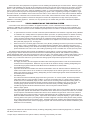
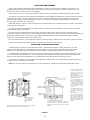
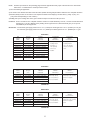
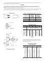
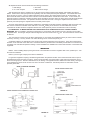
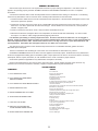
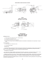
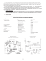
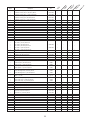
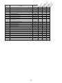
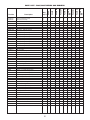
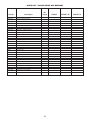
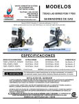
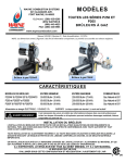
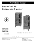
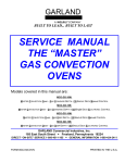
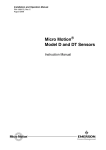
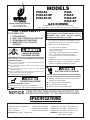
MODELS
P250AF
P250AF-EP
P250AF-DI
P265
P265F
P265-EP
P265-EP
GAS BURNER
WAYNE COMBUSTION SYSTEMS
801 GLASGOW AVE.
FORT WAYNE, IN 46803
Publication Date 5/01 - Revision B - Manual 101220
NOTE: Dimensions in ( ) are informational only. English values take priority.
FOR YOUR SAFETY
IF YOU SMELL GAS:
1. OPEN WINDOWS
2. DON’T TOUCH ELECTRICAL SWITCHES
3. EXTINGUISH ANY OPEN FLAME
4. IMMEDIATELY CALL YOUR GAS
SUPPLIER.
WARNING: If the information in these
instructions is not followed exactly, a fire or
explosion may result causing property
damage, personal injury or death.
-
Do not store or use gasoline or other flammable vapors
and liquids in the vicinity of this or any other appliance.
-
WHAT TO DO IF YOU SMELL GAS
• Do not try to light the appliance.
• Do not touch any electrical switch; do not use any
phone in your building.
• Immediately call your gas supplier from a neighbor’s
phone. Follow the gas supplier’s instructions.
• If you cannot reach your gas supplier, call the fire
department.
CARBON MONOXIDE
POISONING HAZARD
CARBON MONOXIDE IS A COLORLESS, ODORLESS GAS
THAT CAN KILL. FOLLOW THESE RULES TO CONTROL
CARBON MONOXIDE.
Do not use this burner if in an unvented, enclosed area. Carbon
monoxide may accumulate.
Do not adjust the pressure regulator. High pressures produce
carbon monoxide.
Check flue gases for carbon monoxide. This check requires
specialized equipment.
Allow only qualified burner service persons to adjust the burner.
Special instruments and training are required.
Read the owner’s manual before using.
OVERHEATING HAZARD
SHOULD OVERHEATING OCCUR:
Shut off the manual gas valve to the appliance.
Do not shut off the control switch to the pump or blower.
NOTICE
-
Installation and service must be performed by a qualified
installer, service agency or the gas supplier. Warranty is
voided if not installed by qualified service person.
ELECTRIC SHOCK HAZARD
HIGH VOLTAGES ARE PRESENT IN THIS EQUIPMENT.
FOLLOW THESE RULES TO AVOID ELECTRIC SHOCK.
Use only a properly grounded circuit. A ground fault
interrupter is recommended.
Do not spray water directly on burner.
Turn off power before servicing.
Read the owner’s manual before using.
THESE INSTRUCTIONS SHOULD BE AFFIXED TO THE
BURNER OR ADJACENT TO THE HEATING APPLIANCE.
SPECIFICATIONS
BURNER MODELS
MINIMUM INPUT
MAXIMUM INPUT
P-250AF & P-250AF-EP & P250AF-DI
50,000 BTU/HR (14.65 kW/Hr)
250,000 BTU/Hr (73.27 kW/Hr) Natural & L.P. Gas
P-265 & P-265-EP
65,000 BTU/HR (19.05 kW/Hr)
200,000 BTU/Hr (58.61 kW/Hr) Natural & L.P. Gas
P-265-F & P-265F-EP
65,000 BTU/HR (19.05 kW/Hr)
200,000 BTU/Hr (58.61 kW/Hr) Natural & L.P. Gas
ELECTRICAL Power Supply - 115V/60HZ 1 Ph.
FUELS
MOUNTING: Adjustable Flange is Standard
Pedestal Mount is Optional.
These instructions were prepared for the guidance of those installing this particular gas conversion burner. While thy apply in
principle to all installations, they should not be interpreted as meaning the only safe and economical way to install a conversion
burner. It may be necessary to deviate from these instructions in some instances in order to comply with local gas company
rules or codes in effect in the area in which the installation is made. It is recommended that the installer confer with the local
gas company and with the proper municipal officials regarding any specific code or regulation governing the installation of gas
conversion burners, the installation must conform with local codes or, in the absence of local codes, with the American National
Standard Installation of Domestic Gas Conversion Burners, Z21.8-1984, and the National Fuel Gas Code, ANSI Z223.1-1984.
Safe and Economical operation of the burner throughout its service life is dependent to a large extent upon its proper
installation in the heating appliance. Therefore, we may impress upon the installer that good clean workmanlike installations
mean satisfied customers.
VISUAL INSPECTION OF THE HEATING SYSTEM
A conversion burner shall not be installed in an appliance located in a room or basement where facilities for normal air
circulation or infiltration are so limited so as to interfere with ready obtainment of all air necessary for proper combustion and
draft hood dilution, unless at the time of burner installation special provisions are made for combustion and draft hood dilution
air.
a.
In open basements of homes of normal construction (without basement storm windows or tight stair doors) infiltration
of combustion air is usually sufficient to replace that drawn up the flue, so special provisions are seldom necessary.
b.
When the heating appliance is installed in a tightly close room without ventilating openings to outdoors or other
rooms, provisions shall be made for suppling air for combustion through special openings, one near the floor line
and the other near the ceiling, each to be sized on the basis of one square inch or more of free area for each 1,000
BTU (.2931 kW) input per hour. See Figure 1.
c.
When the house is of unusually tight construction, has a (kitchen) ventilating fan which may be used for exhausting
air to indoors, or has a vented fireplace, it is recommended that combustion air be supplied to the furnace room
through intakes extending to the outside of the building and terminating in down turned fittings, suitably arranged to
prevent obstruction from snow or rain, and including a protecting screen not smaller than 1/4-inch (6.35 mm) mesh.
The heating system (both the heat exchanger and distribution system) shall be of a size to properly heat the building.
Through inquiry it shall be determined that all rooms have been heated adequately without wide variations in temperature,
without objectionable drafts, and without excessive fuel costs in the past. If the heating system is deficient with respect to any of
the above determinations, provisions shall be made to correct the deficiency, replace obsolete parts, or (by storm windows,
insulation, etc.) to reduce the heat loss to a point where the existing system will provide the proper amount of heat.
a.
Gravity Warm Air System
The supply and return ducts and registers should be sized and arranged so that the house can be heated without
excessive furnace temperatures. Reference may be made to the American Society of Heating, Refrigerating and
Air-Conditioning Engineers Guide and Data Book series and Handbook of Fundamentals.*
b.
Forced Warm Air Systems
Inspection should also show whether the electrical characteristics of the fan and limit switch are satisfactory and
whether the air filters and fan are in condition for continued proper service with the gas burner, reference may be
made to the American Society of Heating, Refrigerating and Air-Conditioning Engineers Guide and Data Book series
and Handbook of Fundamentals.*
c.
Hot Water Systems
The boiler thermometer and altitude gauge should be in good order. On a closer system, the feed and pressure
relief valves shall be in proper operating condition. If there is an expansion tank on a closer system, inspection
should show it to be substantially empty of water. When there is an existing water temperature limiting switch, its
operating and electrical characteristics shall be checked to determine its suitability to the gas control circuit. For
common piping systems reference can be made to the American Society of Heating, Refrigerating and AirConditioning Engineers Guide and Data Book series* and to the Hydronic Institute Guides.**
d.
Steam or Vapor System
The system shall be pressure tight, with pressure gauge and pop safety valve in good condition and with an existing
water glass which permits clear observation of boiler water level. When there is a pressure limit switch or low-water
cut-off, inspection shall determine whether either device can be utilized in the gas burner control circuit, reference
should be made to the American Society of Heating, Refrigerating and Air-Conditioning Engineers and Institute of
Boiler and Radiator Manufacturers guides. Traps and air vents shall be of adequate capacity, in good condition, and
correctly placed in the system. (Coal firing tends to maintain a slight but continuous steam pressure which prevents
air from being drawn back into the steam system. Intermittent gas burner operation and resultant intermittent steam
supply usually introduces the need for repurging the system of air each time the boiler is steamed if satisfactory heat
distribution is to be achieved.)
*copies may be obtained from the American Society of Heating, Refrigerating and Air-Conditioning Engineers, Inc., 345 East
47th Street, New York, NY 10017.
** Copies may be obtained from the Hydronic Institute, 35 Russo Place, Berkeley, NJ 07922.
1
FLUE PIPE AND CHIMNEY
The flue pipe should be carefully inspected and replaced if necessary in connection with installation of a draft hood. All
installations must operate with a negative draft overfire. Refer to your local gas company or codes for assistance or to the
furnace and/or boiler manufacturer for recommendations.
The flue pipe entrance into the chimney should be at least two feet (.610m) above the clean-out opening in the chimney.
The chimney should extend high enough above the dwelling or other neighboring obstructions so that wind from any direction
will not strike the chimney from any angle above horizontal. Unless the obstruction is of greater magnitude, it is the usual
experience that a chimney extending two feet above flat roofs or above fire wall parapets, and peaked roofs within 30 feet
(9.144m) will be reasonably free of downdraft.
Where the chimney is unlined or where local experience indicates that flue gas condensate might be a problem, the local gas
company should be consulted.
The chimney should be examined and thoroughly cleaned, if necessary, before installation is made to make sure it freely
conduct the flue gases to the outside.
Flue pipe should extend through the chimney wall to inner face of chimney liner but not beyond, and should be firmly
cemented to masonry. A thimble may be used to facilitate removal of flue pipe for cleaning, in which event the thimble should be
permanently cemented in place with mortar or other fireproof material that will not crack or check the flue pipe or thimble,
whichever is used, should be sealed into the chimney liner.
Flue connections from two or more appliances should not enter opposing or adjacent sides of the chimney at the same level.
Under no circumstances should the flue pipe be connected it to a flue of an open fireplace.
INSPECTION OF HEATING APPLIANCE
A careful inspection of furnace or boiler should be made. If cracked heating sections, leaking soft plugs or any other
condition which might make the unit unsatisfactory for gas conversion is found, proper arrangements should be made for
replacement or repair before proceeding with the burner installation. Cracked heating sections should be replaced.
A neutral pressure point adjuster, similar to the one shown in figure 2 may be installed in the flue pipe between the furnace
and a conventional type CSA draft hood. The neutral pressure point adjustment should be left in the fully open position until
after the burner rating has been established. The material used for flue pipe should be resistant to corrosion.
The necessity for installing a neutral pressure point adjuster as outlined above, may be eliminated by reducing the flue pipe
and draft hood to the sizes shown in the table.
NOTE: For oil fired conversions consult boiler or furnace manufacturer. Appliance must maintain negative draft overfire.
NOTE: Ducts used for make-up
air may be connected to the
cold air return of the heating system only if they connect
directly to outdoor air.
Air Inet Opening 1 Sq.
in. (645.2 mm2) for each
1,000 Btu (.2931 kW)
per hour input.
Attic Ventilation Louvers are
required at each end of attic
with alternate air inlet No. 1.
1, 2, and 3 mark alternate locations for air from outdoors. Free
area shall be not less than 1 Sq.
in. (645.2 mm2) per 5,000 Btu
(.1.465 kW) per hour of the total
per hour of the total input rating
of all appliances in the
enclosure.
Crawl-space Ventilation Louvers
for unheated crawl space
are required with alternate air
inlet No. 3.
Each Ventilation Air Opening
from inside the building shall
have a free area of not less than
1 Sq. in. (645.2 mm2) per 5,000
Btu (.1.465 kW) per hour of the
total per hour of the total input
rating of all appliances in the
enclosure.
Ventilating Air Opening
1 Sq. in. (645.2 mm2)
for each 1,000 Btu
(.2931 kW) per hour
input.
Application located in confined spaces. Ventilation air
from inside building - combustion and draft hood
dilution air from outside. Ventilated attic or ventilated
craw space.
Illustration showing air opening necessary to supply air for combustion
when heating appliance is installed in an enclosed room.
FIGURE 1
2
1/2” (12.7 mm)
FIGURE 2
FIGURE 3
Minimum rise 1/4” (6.35
mm) to the foot (.305 m)
Minimum rise 1/4” (6.35
mm) to the foot (.305 m)
Minimum rise 1/4” (6.35
mm) to the foot (.305 m)
90˚ (1.57 rad) ANGLE TYPE DRAFT HOOD
(Always install in a vertical position)
FIGURE 4
3
PREPARATION OF FURNACE OR BOILER
Clean combustion chamber thoroughly. Scrape and brush all heating surfaces and flue ways. Soot and fly ash are excellent
insulators and unless removed the efficiency of the heating plant will be impaired. Plugged or restricted flue passages will
prevent burner from operating properly.
Be sure water column and gauge on boiler is clean and water level is visible. In all cases make sure the pigtail to limit control
is clear. Safety pop valves on team boilers and automatic relief valves on closed water systems should be thoroughly checked
to make sure they are in good working condition.
FLUE PIPE AND DRAFT HOOD
A CSA type draft hood or its equivalent shall be placed in and made part of the flue pipe from the appliance. At no time
should the draft hood be located at a point lower than the highest flue passage in the appliance. The draft hood should be
installed in the position for which it was designed and in no case installed in a false ceiling, separate room from the heating
appliance, or in any other manner that will permit a difference in pressure between the draft hood relief opening and the
combustion air supply. On sealed type appliances where all combustion air is taken from the outside, a cap should be installed
on end of flue pipe to prevent back drafts. In such cases no draft hood or diverter should be installed inside. See Figure 4.
When converting oil fire appliances the flue pipe and draft hood or diverter used should be the same size as the furnace flue
collar. It is recommended that a rise as great as possible or at least 1/4 inch (6.35mm) to the foot (.305m) (horizontal length) be
maintained in the flue pipe from the appliance to the chimney. The flue pipe should be relocated where possible to avoid sharp
turns.
DRAFT HOOD & FLUE PIPE SIZES FOR GAS CONVERSION
BURNERS IN UP-DRAFT COAL FURNACES ND BOILERS
Not more than 6,500 BTU (1.905 kW) per inch (645.2 mm2) of the flue area
Input - BTU (kW)
Per Hour
Draft Hood and
Flue Pipe Size
Up to --- 120,000 (35.17)
5 inch (127mm)
120,000 (35.17) --- 180,000 (52.75)
6 inch (152.4mm)
180,000 (52.75) --- 250,000 (73.27)
7 inch (177.8mm)
NOTE: If the flue pipe exceeds 10 ft. (3.048m) in length, or contains more than two elbows, use next size larger pipe and
draft hood.
NO MOVEABLE FLUE PIPE DAMPER SHOULD BE USED ON ANY INSTALLATION.
NOTE: All installations must operate with negative draft overfire. Refer to your local gas company and codes for assistance.
REVERTIBLE FLUE (DOWN DRAFT OR DIVING FLUE TYPE) FURNACES OR BOILERS
When installing the burner in the above type furnaces or boilers, the draft hood (or draft diverter) should be located at least
one foot higher than the top of the highest point of the appliance flue passage or combustion chamber. It is also recommended
that a vent pipe, not less than one inch in diameter, be provided from the highest point in the flue passage, directly to the flue
pipe. This is not necessary on the appliances with built in up draft bypass. (See Figure 3.) The gas company serving the area
should be consulted in regards to their recommendations for converting this type of furnace or boiler.
The flue pipe should be securely supported and the joints fastened with sheet metal screws or riveted to prevent sagging,
and in no case should be located in a manner that will present a hazard to combustible building material. (Refer to local building
code.)
PREPARATION OF COMBUSTION CHAMBER
THE POWER GAS BURNER IS DESIGNED FOR “INSHOT” FIRING INTO A REFACTORY LINED COMBUSTION
CHAMBER CONSTRUCTED IN THE ASH PIT OF ANY BOILER OR FURNACE ORIGINALLY DESIGNED FOR COAL OR OIL
FIRING. THE SIZE, SHAPE AND CONSTRUCTION OF THE CHAMBER SHOULD BE GIVEN SUCH CONSIDERATION AS
WILL RESULT IN THE MAXIMUM EFFICIENCY OF EACH INSTALLATION.
On smaller inputs precast chambers may be used if the firing door and ash pit are large enough to insert the chambers and
assemble.
When converting oil designed boilers and furnaces, it is recommended that the same combustion chamber be used with the
gas burner. If the blast tube opening into the combustion chamber is larger than the 4” (101.6mm) diameter, high temperature
cement should be used to reduce the opening to 4” (101.6mm) diameter.
IN NO CASE SHOULD THE TUBE BE ALLOWED TO EXTEND INTO THE CHAMBER PROPER. IT MUST BE AT LEAST
1/8” (3.175mm) SHORT OF THE INSIDE SURFACE OF THE COMBUSTION CHAMBER.
4
COMBUSTION CHAMBERS
The combustion chamber sizes given in Figure 5 are based on the maximum rated BTU capacity. If the input is to be
permanently set at a reduced rate, the combustion chamber floor area can be reduced proportionately to the proposed input,
allowing 200,000 BTU (211000kJ) per square foot (.093m2) of combustion chamber floor area and proportioning the length about
70% greater than the width.
The height of the walls of the combustion chamber is generally determined by the grate line. The side and front walls should
be built about 2” (50.8mm) above the grate line, covering the grate lugs and covering the bases of the water legs of boilers
about 3” (76.2mm) or 4” (101.6mm) to avoid heating sections that may be filled with sediment. The back wall should be carried
one or two courses higher and overhung to deflect hot gases from direct impingement on the rear heat exchanger surfaces.
Hard firebrick should be used for the overhung section to prevent erosion of the brick at this point by the high velocity gases
m9moving over it.
The remaining open spaces between the combustion chamber and ash pit walls should be filled with loose insulation. Since
this insulation may not stand combustion chamber temperatures, the top course of the combustion chamber walls be laid flat,
extending to, and fitting the contour of the firebox and covering the loose insulation.
Always use cement furnished by the brick manufacturer for cementing insulating firebrick. It should be thinned to the
consistency of a very thick cream so that the brick can be dipped into it and set in place. The use of other cement or mortar
may impair the insulating and radiating qualities of the brick.
Magnesia block insulation, common brick, hard fire brick, dry sand and/or expanded mica products such a “Vermiculite” or
“Zonolite” can be used to back up the insulating firebrick. High temperature furnace cement can be used to seal the openings
around the burner and furnace.
Approved insulating bricks are: Babcock & Wilcox No. K-23 and No. K-26, A. P. Grenn No. G-23 and No. G-26, Armstrong
Cork No. A-23 and No. A-26 an Johns Manville No. JM-23 and No. JM-26.
INSTALLATION OF BURNER AND CONTROLS
The inshot power gas burner was designed especially for converting gun fired oil designed furnaces and boilers. Due
consideration was given to making it as simple and easy to install and service as possible without weakening its durability or
efficiency. The burner is supplied as a completely assembled package unit.
NOTE: The burner must be installed in such a manner that they unit and all controls will be readily accessible for inspection,
cleaning, adjustment and repairs.
SIZING OF INPUT IN RELATION TO FURNACE
FIGURE 140,000 BTUs (147700KJ) per gal. of oil input. For example: Furnace rating 0.60 G.P.H. then 0.60 x 140,000 =
72,000 BTUs input rate
The orifice spud supplied with all burners is the size for the minimum BTU input of the burner for the type gas shown on the
rating plate. Figure 6 shows the correct drill size for various inputs.
The correct manifold pressure for natural gas is 3.5” w.c(871.8 Pa). Only minor adjustments in the input rate should be made
by adjusting the pressure regulator. The minimum manifold pressure should be 3.0” w.c. (747.2Pa) and the maximum pressure
should be 3.5 w.c. (871.8 Pa) the next size larger or smaller orifice size should be used if the desired input rating cannot be
obtained within the above manifold pressure adjustment range.
The correct manifold pressure for L.P. gas is 10” w.c. (2491Pa), only minor adjustments in the input rate should be made by
adjusting the pressure regulator. The minimum manifold pressure should be 9.5” w.c. (2366 Pa), the maximum pressure 10.0”
w.c. (2491 Pa). If the desired input rating cannot be obtained within the above manifold pressure and adjustment range then the
next size larger or smaller drill should be used.
B.T.U. (kW)
INPUT
PER HOUR
50,000 (14.65)
75,000 (21.98)
90,000 (26.38)
100,000 (29.31)
125,000 (36.63)
130,000 (38.1)
150,000 (43.96)
160,000 (46.89)
175,000 (51.29)
180,000 (52.75)
200,000 (58.61)
225,000 (65.94)
242,000 (70.92)
250,000 (73.27)
NATURAL GAS
3 1/2” (871.8Pa) W.C.P.
Drill Size
#30 (3.264mm)
5/32 (3.967mm)
#17 (4.394mm)
#14 (4.623mm)
#5 (5.22mm)
#4 (5.309mm)
#1 (5.791mm)
15/64 (5.954mm)
C (6.147mm)
1/4 (6.35mm)
G (6.629mm)
J (7.036mm)
L (7.366mm)
M (7.493mm)
FIGURE 6
5
PROPANE GAS
10” (2491 Pa) W.C.P.
Drill Size
#45 (2.083mm)
#41 (2.438mm)
#37 (2.642mm)
#35 (2.794mm)
1/8 (3.175mm)
#30 (3.264mm)
#29 (3.454mm)
#28 (3.569mm)
#26 (3.734mm)
#25 (3.797mm)
#22 (3.988mm)
#19 (4.216mm)
#17 (4.394mm)
#16 (4.496mm)
NOTE: The BTU input valves on the preceding page show the approximate hourly input of the burner for the various drill
sizes shown. To determine the actual input of the burner:
1) Turn off all other gas appliances.
2) The hand on the dial with the lowest cubic feet value (fastest revolving dial) should be clocked for one complete revolution.
3) Divide 3,600 by the time in seconds for one complete revolution and multiply by the dial value (1 (.028), 2 (.057), or 5
(.142) cubic feet depending on size of meter.)
4) Multiply this by the heating value of the gas to obtain the input to the burner in BTU per hour.
EXAMPLE: Time in seconds for one complete revolution of dial is 72. 3,600 divided by 72 is 50, a 2 cubic foot dial was timed
therefore 50 x 2 is 100. Multiply 100 by heating value of gas which is 1,000 and this will give you an input of
100,000 BTU (29.31 kW) per hour.
IMPORTANT: The minimum gas supply pressure is 4.5” w.c. (1121Pa) for natural gas and 11.0” w.c. (2740Pa) for L.P. gas;
the maximum gas supply pressure is 10.5: w.c. (2615Pa) for natural gas and 13” w.c. (3238Pa) for L.P. gas.
P250 ONLY
Input
BTU/Hr.
(kW/Hr.)
Floor Area
Sq. Inches
2
(mm )
Preferred
Width and
Length (mm)
Recommended
Minimum
Wall Thickness
50,000 (14.65)
49 (31610)
7(177.8)x7 (177.8)
85,000 (24.91
56 1/4 (36290)
7 1/2(190.5)x7 1/2(190.5)
Recommended
Minimum
Floor Construction
2 1/2” (63.5mm)
2 1/2” (63.5mm)
insulating firebrick
Insulating firebrick
100,000(29.31)
64 (41290)
8(203.2) X 8(203.2)
plus back up of
plus 1 1/2” (38.1mm)
120,000(35.17)
72 1/4 (46610)
8 1/2(215.9) x * 1/2(215.9)
1 1/2” (38.1mm)
asbestos or magnesia
or more loose
block.
140,000(41.03
81 (52260)
9(228.6) x 9(228.6)
154,000(45.13)
90 1/4 (58230)
9 1/2(241.3) x 9 1/2(241.3)
175,000(51.29)
100 (64520)
10(254) X 10(254)
210,000(61.55)
122 (78710)
11(279.4) X 11(279.4)
240,000(70.34)
144 (92900)
12(304.8) x 12(304.8)
250,000(76.2)
156 1/4 (100800)
12 1/2(317.5) X 12 1/2(317.5)
insulation.
FIGURE 5
P265 ONLY
Input
BTU/Hr.
(kW/Hr)
Floor Area
Sq. Inches
2
(mm )
Preferred
Width and
Length (mm)
Recommended
Minimum
Wall Thickness
Recommended
Minimum
Floor Construction
65,000 (19.05)
63 (40650)
7 (177.8) x 9 (228.6)
2 1/2” (63.5mm) insulating
2 1/2” (63.5mm) insulating
75,000 (21.98)
71 1/4 (45970)
7 1/2 (190.5) x 9 1/2 (241.3)
firebrick plus back up
firebrick plus 1 1/2” (38.1mm)
100,000 (29.31)
180 (116100)
7 1/2 (190.5) x 9 1/2 (241.3)
of 1 1/2” (38.1mm) or
asbestos or magnesia
150,000 (43.96)
200 (129000)
12 (304.8) X 15 (381)
more loose insulation.
block.
200,000 (58.61)
220 (141900)
13 (330.2) x 17 (431.8)
FIGURE 5A
P265F ONLY
Input
BTU/Hr.
(kW/Hr.)
Floor Area
Sq. Inches
2
(mm )
Preferred
Width and
Length (mm)
Recommended
Minimum
Wall Thickness
65,000 (19.05)
63 (40650)
7 (177.8) x 9 (228.6)
2 1/2” (63.5mm) insulating
75,000 (21.98)
63 (40650
7 (177.8) x 9 (228.6)
firebrick plus back up
firebrick plus 1 1/2” (38.1mm)
100,000 (29.31)
71 1/4 (45970)
7 1/2 (190.5) x 9 1/2 (241.3)
of 1 1/2” (38.1mm) or
asbestos or magnesia
150,000 (43.96)
110 (70970)
10 (254) x 11 (297.4)
more loose insulation.
block.
200,000 (58.61)
165 (106500)
11 (297.4) x 15 (381)
FIGURE 5B
6
Recommended
Minimum
Floor Construction
2 1/2” (63.5mm) insulating
ELECTRICAL WIRING
The power burner is shipped completely wired. It is only necessary to supply the 115 volt circuit, thermostat and limit circuit.
All wiring must conform with the National electric Code or the code legally authorized in the locality where the installation is
being made. The burner, when installed, must be electrically grounded in accordance with local codes or, in the absence of
local codes, with the National Electrical Code, ANSI/NFPA No. 70-1987. See wiring diagrams, Figures 12&13.
If an external electrical source is utilized, the conversion burner, when installed, must be electrically grounded in accordance
with local codes or, in the absence of local codes, with the National Electrical Code ANSI/NFPA No. 70-1987.
CAUTION: Label all wires prior to disconnection when servicing controls. Wiring errors can cause improper and dangerous
operation. Verify proper operation after servicing.
LIMIT CONTROL SWITCHES
Warm air furnaces (gravity and forced air) should be equipped with an automatic temperature limit control switch. Hot water
boilers (forced or gravity) should be equipped with an automatic temperature limit control switch.
Steam or vapor boilers be provided with means to guard against firing a dry boiler or one in which the water is dangerously low.
IMPORTANT: On installations where an oil burner replaced with a gas burner, the controls on the boiler or furnace will have
to be checked for compatibility with the gas burner. All controls should be checked to insure that they operate
properly and that they are in good condition. In no case should any limit or safety control be bypassed or
wired in such a manner that it will result in unsafe operation of the burner or appliance. If the controls on the
appliance are not compatible with the burner operation they should be replaced with the proper controls.
THERMOSTAT
The thermostat should be installed on an inside wall and should be located in the natural circulating path of room air.
Locations which would expose the thermostat to cold air, or drafts from windows, door, or openings leading to the outside, or to
air currents from cold or warm air registers, or where the natural circulation of air is shut off such as behind doors, above or
below mantels, shelves or in corners, should be avoided. The thermostat should not be exposed to heat from nearby radiators,
lamps, rays of the sun or mounted on a wall near pipes, warm air ducts or chimney flue. Any hole in the plaster or panel
through which the thermostat wires pass should be sealed to prevent drafts.
The maximum comfort to be obtained from any automatic heating installation is dependent to a great extent upon the proper
installation and adjustment of the room thermostat.
GAS PIPING
All piping must comply with local codes and ordinances or the National Fuel Gas Code ANSI Z223. 1-1984 and NFPA No.
54. A sediment trap or drip leg must be installed in the supply line to the burner.
A union shall be installed in the gas line adjacent to the upstream from the control manifold and downstream from the manual
main shutoff trap or drip leg must be installed in the supply line to the burner.
A 1/8” N.P.T. (3.175mm) plugged tapping accessible fro test gauge connection shall be installed immediately upstream of the
gas supply connection for the purpose of determining the gas supply pressure to the burner.
A manual shutoff valve shall be installed in the gas supply line external to the appliance, see Figure 7.
The gas line should be a separate supply direct from the meter to the burner. It is recommended that new pipe; be used and
located so that a minimum amount of work will be required in future servicing. The piping should be so installed as to be
durable, substantial and gas tight. It should be clear and free from cutting burrs and defects in structure or threading. Cast iron
fittings or aluminum tubing should not be used for the main gas circuit. Joint compounds (pipe dope) should be used sparingly
on male threads only and be approved for all gases.
It is recommended that table 8 be used to determine the size pipe to use from the meter to the burner.
The building structure should not be weak ended by installation for the gas piping. The piping should not be supported by the
other piping, but should be firmly supported with pipe hooks, straps, bands or hangers. Butt or lap welded pipe should not be
bent.
The gas piping should be so installed so as to prevent an accumulation of condensation and it must be protected against
freezing. A horizontal pipe should be pitched so that it grades toward the meter and is free from sags. The pipe should not be
run through or in an air duct or clothes chute.
The appliance and its individual shutoff valve must be disconnected from the gas supply piping system during any pressure
testing of the system at test pressure in excess of 1/2 (3447 PaG) psig.
The appliance must be isolated from the gas supply piping system by closing its individual manual shutoff valve during any
pressure testing of the gas supply piping system at test pressures equal to or less than 1/2 (3447 PaG) psig.
TESTING PIPING FOR LEAKS
Before turning gas under pressure into piping, all openings from which gas can escape should be closed. Immediately after
turning on gas, the system should be checked for leaks. This can be done by watching the 1/2 cubic feet (.014m3) test dial and
allowing 5 minutes to show any movement, or by soaping each pipe connection and watching for bubbles. If a leak is found,
make the necessary repairs and repeat the above test.
Defective pipes or fittings should be replaced and not repaired. Never use a flame or fire in any form to locate gas leaks, use
a soap solution.
7
After the piping and meter have been checked completely, purge the system of air. Do not bleed the air inside the furnace.
Be sure to relight all the gas pilots on other appliances.
PURGING
After the piping has been checked, all piping and appliances receiving gas through the meter shall be fully purged. A
suggested method for purging th gas line to the burner is to disconnect the pilot line at the outlet o the pilot valve. Under no
circumstances shall th line be purged into the combustion chamber.
After th e gad line to the conversion burner has been fully purged and the pilot line reconnected, the gas supply at other pilot
burners located on other gas appliances which were extinguished as the result of interrupted service shall be reignited.
LENGTH OF STANDARD PIPE THREADS inches (mm)
PIPE SIZE
EFFECTIVE
LENGTH
OF THREAD
OVERALL
LENGTH
OF THREAD
3/8 (9.525)
1/2 (12.7)
3/4 (19.05)
1 (25.4)
3/8 (9.525)
1/2 (12.7)
1/2 - 9/16 (14.29)
9/16 (14.29)
9/16 (14.29)
3/4 (19.05)
13/16 (20.64)
1 (25.4)
PIPE CAPACITY TABLE
Nominal Diameter of Pipe in Inches
3/4 (19.05) 1(25.4) 1-1/4 (31.75) 1-1/2 (38.1)
Length
of Pipe
in Feet
15 (4.572)
30 (9.144)
45 (13.72)
60 (18.29)
75 (22.86)
105 (32)
120 (36.58)
180 (54.86)
2 (50.8)
Capacity - Cu, Ft. Per Hr. with a 0.6
Sp. Gr. Gas and Press. Drop of 0.3 In. (74.72 Pa) Water Col.
172
345
750
120
241
535
850
99
199
435
700
86
173
380
610
77
155
345
545
65
131
285
450
920
120
270
420
860
100
225
350
720
FIGURE 8
To convert the figures given above to capacities for another
gas of different specific gravity, multiply the tabular values by
the multiplier shown below.
SPECIFIC
GRAVITY
.35
8
MULTIPLIER FOR VARIOUS
SPECIFIC GRAVITIES
SPECIFIC
MULTIPLIER
GRAVITY
MULTIPLIER
1.31
1.00
.775
.40
1.23
1.10
.740
.45
.50
.55
.60
.65
.70
.75
.80
.90
1.16
1.10
1.04
1.00
.962
.926
.895
.867
.817
1.20
1.30
1.40
1.50
1.60
1.70
1.80
1.90
2.10
.707
.680
.655
.633
.612
.594
.577
.565
.535
ADJUSTMENT OF BURNER
Starting the burner:
1. Depress the gas valve control knob on the combination gas valve and turn to “OFF”. Figure 9.
2. Set room thermostat above room temperature and let burner run five minutes to purge the unburned gas from the unit.
3. Set thermostat below room temperature.
4. Turn gas valve control to “PILOT”.
5. Depress red button on valve to start pilot gas flow.
6. Push re button down on spark generator until it snaps. Repeat this until the pilot lights. Note: this may take some time until
all the air is “bled: out of the line.
7. Hold the red button on the valve for seconds, then release.
8. Observe pilot - if not lit, SHUT OFF BURNER COMPLETELY AND WAIT 5 MINUTES. Repeat steps 1 through 7.
9. Turn gas control valves to “ON”.
10. Set room thermostat higher than room temperature so that the burner will start.
To put burner out of operation
1. Depress the gas valve control knob on the combination gas valve and turn to “OFF”.
2. Turn off electrical supply.
STANDING PILOT
COMBINATION GAS VALVE
FIGURE 9
ELECTRONIC PILOT
FIGURE 11
9
P265DI - JUNCTION BOX ROTATED
P265DI
10
All adjustments below must be made with the following instructions:
1. Draft Gauge
2. O2 or CO2 Analyzer
3. CO Tester
4. Water Column Gauge
After the burner has been in operation for 10 minutes and if a neutral pressure point adjuster was installed, proceed as
follows. Start from the wide open position and gradually close the neutral pressure point adjustment. Crack observation door
about 1/8 inch (3.175mm). Then by holding match flame along opening, the neutral pressure point can be determined. The
flame should be drawn in below the center of the door and it should be blown outward above the center. In other words, the
pressure inside the combustion chamber should be above atmospheric pressure above the burner flame and below atmospheric
pressure below the burner flame. The pressure should be neutral at the center. Closing the adjuster lowers the neutral
pressure point and opening the adjuster raises the neutral pressure point.
Once the neutral pressure point has been adjusted, the combination air shutter should be adjusted so that the percent CO2
test must be made at the inlet side of the draft hood. If the CO2 reading is not within the recommended limits, then the
combustion air shutter should be re-adjusted and then the neutral pressure point be rechecked and reset if necessary.
IT IS ESSENTIAL TO MAKE CERTAIN THAT THE PRODUCTS OF COMBUSTION DO NOT CONTAIN CARBON
MONOXIDE, CO. It is possible to have flame impingement on cold surfaces with resultant CO even if CO2 and O2 are within
acceptable limits. The flue gas sample is taken through the same hole used for the CO2 test. CO test instrument must be used
for this test.
The most common causes of CO are flame impingement on cool surface and insufficient primary air, both of which could be
caused by over firing. The only answer is to reduce the firing rate or increase the primary air.
Combustion efficiency is determined by the percent CO2 and the temperature of the flue gases. These two measurements
are taken on the inlet side of the draft hood. Combustion efficiency and stack loss calculators provide slide rule convenience for
correlating CO2 and stack temperature readings. These calculators are available from several manufactures of combustion test
equipment.
IMPORTANT
DRAFT - When installing Wayne power gas burners in oil fired boilers a minimum negative draft of .02” (4.982 Pa) w.c. over
fire must be maintained.
Refer to your local gas company and codes for assistance.
For gad fired equipment requiring a double acting barometric the preferred location of the barometric draft control is part of
the bullhead tee shown in figures A, B OR C. During normal operation, flue gases make a right angle turn behind the control,
but do not infringe upon it. Should a downdraft occur, air flowing n the opposite direction strikes the control directly, causing it to
open outwardly and vents the air into the room with a minimum of resistance. Entrained products of combustion are thus
provided grater relief.
BEST LOCATIONS FOR GAS
WIRING DIAGRAM LADDER FORM
FIG. A
FIG. B
FIG. C
FIGURE 12
WIRING DIAGRAM FOR GAS BURNER WITH STANDING PILOT
WIRING DIAGRAM LADDER FORM
FIGURE 13
11
GENERAL INSTRUCTION
Gas burners require the services of an experienced technician for proper setting and adjustment. If the burner does not
appear to be operating properly, DO NOT ATTEMPT TO ADJUST THE BURNER YOURSELF, but call in a competent
serviceman.
A homeowner should be able to check several possible causes of shutdown before calling in a serviceman. The following
check list may eliminate the need for a service call or at least provide information for the serviceman.
1. Check thermostat. Make sure that it is set at the desired room temperature. If the thermostat is damaged or loose on the
wall, have it replaced or repaired.
2. Check fuses in service box for the burner circuit. Replaceable type fuses should not be loose in the socket. If a fuse is
blown out or if in doubt, replace with the same size and type. If circuit breaker are in the service box, check position of
indicator. If tripped, reset.
3. Check on-off switch for the burner circuit, it may have been accidentally turned off.
4. With the thermostat set 10 degrees above room temperature, the burner should start automatically. If it does not start,
check pilot. If no flame is visible, relight pilot following lighting instructions.
It is advisable, periodically, to visually inspect the burner. Check air inlet blower to make sure it is not clogged or
blocked. Check air shutter to make sure that it has not been tampered with, make sure that it is in the same position as
when final adjustments were made. Check blower wheel to see if it is dirty or full of lint. Open observation door and
check pilot flame. If the flame does not appear normal or if in doubt, call a serviceman.
The areas around the conversion burner should be kept clear and free of combustible materials, gasoline and other
flammable vapors and liquids.
The flow of combustion and ventilating air to the burner must not be blocked or obstructed in any manner.
CLEANING OF BURNERS: Remove the burner from the appliance and visually inspect the blast tube for any deterioration.
On burners equipped with standing pilot or intermittent ignition, inspect pilot burner for dust or corrosion and clean if necessary.
Check pilots, thermo-couples, electrodes, etc. with illustrations in the owner’s manual for proper locations.
Check flame spreaders if applicable for any deterioration and replace if necessary.
Remove corrugated flame ring from the end of the venturi and clean. Visually inspect the inside of the venturi for any
excessive rust or corrosion and clean if necessary. Replace corrugated flame ring and reinstall burner.
SYMPTOMS
1. PILOT DOES NOT LIGHT
2. PILOT GOES OUT FREQUENTLY
DURING STANDBY.
3. PILOT GOES OUT WHEN MOTOR STARTS.
4. MOTOR DOES NOT RUN.
5. MOTOR RUNNING BUT NO FLAME.
6. SHORT NOISY BURNER FLAME.
7. LONG YELLOW FLAME.
8. MAIN GAS VALVE DOES NOT
CLOSE WHEN BLOWER STOPS.
9. REGULATOR VENT LEAKING GAS.
TROUBLE CHART
CAUSE
a. Air in Gas Line.
b. High or low gas pressure.
c. Blocked pilot orifice.
a.
b.
c.
d.
e.
f.
g.
Restriction in the pilot gas line.
Low gas pressure.
Blocked pilot orifice.
Loose thermocouple connection on 100% shut off.
Defective thermocouple or pilot safety switch.
Poor draft condition.
Draft tube set into or flush with inner wall of combustion chamber.
a. Restriction in pilot gas line.
b. High or low gas pressure.
c. Excessive pressure drop when the main gas valve opens.
a.
b.
c.
d.
e.
Burned out fuse or current off.
Thermostat or limit defective or improperly set.
Relay or transformer defective.
Motor burned out.
Improper wiring.
a.
b.
c.
d.
e.
Pilot out.
Thermocouple not generating sufficient voltage.
Very low or no gas pressure.
Vent in regulator plugged.
Defective regulator.
a. Air shutter not open enough.
b. Air openings or blower wheel clogged.
c. Too much input.
a. Hole in diaphragm.
12
P 265-EP, P265F-EP, P250AF-EP
INTERMITTENT PILOT INSTRUCTION
FOR HONEYWELL SYSTEM
STARTING BURNER
1.
2.
3.
4.
5.
Depress the gas valve control knob on the combination gas valve and turn to “OFF”. See Figure 9.
Set the room thermostat above room temperature and wait five (5) minutes.
Set thermostat below room temperature.
Turn gas control valve knob to “ON”.
Set room thermostat higher than room temperature so that the burner will start.
SHUTTING DOWN THE BURNER
1. Depress the gas valve control knob on the combination gas valve and turn to “OFF”.
2. Turn off electrical supply.
OPERATION
FIRST STAGE -- TRIAL FOR PILOT IGNITION
On every call for heat (system start), the S8600 performs an internal safe-start check. A system start is prevented if the
check shows that a flame-simulating condition is present..
During a normal start, the S8600 opens the first operator in the gas control. This allows gas to flow to the pilot burner.
Simultaneously, the electronic spark generator in the S8600 produces a 15,000 volt spark pulse output. This voltage produces a
spark at the pilot burner ignitor-sensor rod, igniting the gas flowing around the electrode. If the pilot flame is not detected during
the trial for pilot ignition, the S86E an F will continue trying for pilot ignition until a flame is established. The S86G and H contain
a safety locknut timer to limit the trial for pilot ignition period.
SECOND STAGE -- MAIN BURNER OPERATION
When the pilot flame is established, a flame rectification circuit is completed to the burner ground. The S8600 flame sensing
circuit detects the flame current and shuts the spark generator off. At the same time the second operator (main) is opened in
the gas control, allowing gas flow to the main burner. The pilot flame ignites the main burner conventionally. On the S86G and
H the flame current also holds the safety lockout timer in the reset, or normal, operating condition.
SAFETY LOCKOUT TIME (S8600 only)
The safety lockout timer circuit starts timing the moment the trial for pilot ignition starts. When the timing period runs out, the
trial for ignition ends, and the control module goes into lockout. Before another attempt to start can be made, the S8600 must
be reset. Reset by adjusting the thermostat or controller below room temperature, or to its “OFF” position. An alternate method
is to shut the system power “OFF”. Wait at least one (1) minute, then turn the system “ON”. If normal ignition does not occur,
use the troubleshooting table to determine the problem.
SERVICE
PRELIMINARY CHECK
The following visual checks should be made before troubleshooting an after installation or maintenance.
1. Check the power to the appliance and S8600.
2. Manual shutoff cocks in gas line to appliance must be open.
3. Make certain all wiring connections are clean and tight.
4. S86G, H module must not be in safety lockout. First de-energize the system and wait at least one(1) minute. This resets
the module, allowing a return to start condition.
5. Review the S8600 system normal sequence of operation.
SYSTEM TROUBLESHOOTING
Start the system by setting the thermostat or controller above required temperature. Observe system response. Establish
type of malfunction or deviation from normal operation. Use the S8600 Intermittent Pilot System Troubleshooting Table (Page
13) to check for normal system operation.
Use table by following instruction question in box. If the condition is true or okay (answers yes), go down to next box
underneath. If the condition is not true or not okay (answers no), go right to the next box alongside. Continue checking and
answering conditions in each box encountered, until a problem and/or the repair are explained. After any maintenance or repair,
the troubleshooting sequence should be repeated until the troubleshooting procedure ends with normal system operation.
13
IMPORTANT: The electronic S8600 Control Module cannot be repaired. If troubleshooting procedure indicates a malfunction in
the S8600 the S8600 Control Module must be replaced. Intermittent pilot systems should be serviced only by
trained and experienced personnel.
SEQUENCE OF OPERATION
1
START
2
THERMOSTAT (CONTROLLER)
CALLS FOR HEAT
SPARK GENERATOR
powered by First Valve (pilot) operator opens
STAGE 1
TRIAL FOR
IGNITION
3
PILOT BURNER OPERATION
Pilot burner lights.
Module senses
flame current.
4
Pilot burner does not light
OR
Module
S8600A,F
S8610A, F
S8600B, H
S8610B, H
S8600M
Response
Ignition spark continues, pilot valve remains
open until system is reset
After 15 or 90 sec. a system
lock outs; must be manually reset
After on sec. a system shuts off; after 5 minutes
min. (6 minutes nom.), module restarts trial for
ignition; ignition trial, shutoff, wait sequence
repeats until pilot lights or call for heat ends.
a Shutoff/lockout timing is stamped on module
FLAME CURRENT SENSED
• Spark generator off
• Second valve operator (main) opens.
STAGE 2
MAIN BURNER
OPERATION
4
POWER INTERRUPTION
System shuts off, restarts when power is
restored.
MAIN BURNER OPERATION
Module monitors pilot flame current.
PILOT FLAME FAILURE
4
END
THERMOSTAT (CONTROLLED)
SATISFIED
Mail valve closes.
Module starts trial for ignition.
Valves close, pilot and main burners are off.
WIRING DIAGRAM HONEYWELL EP SYSTEM
WIRING DIAGRAM LADDER FORM
S86
14
S8600, S8610 TROUBLESHOOTING GUIDE
START
TURN GAS SUPPLY OFF,
TURN THERMOSTAT
(CONTROLLER) TO CALL
FOR HEAT
NOTE: Before troubleshooting, familiarize yourself with the start up and checkout procedure.
NO
POWER TO MODULE
(24V NOMINAL)
Check line voltage power, low voltage transformer, limit controller, thermostat (controller) and
wiring. Also, check air proving switch on combustion air blower system (if used) and that vent
damper (if used) is open and end switch is made.
Pull ignition lead and
check spark at module
YES
NO
SPARK ACROSS
IGNITER/SENSOR GAP
NO
Spark okay?
• On modules with vent damper plug, make sure
vent damper has not been installed, then
removed. Replace vent damper if necessary.
• On other models, replace module.
YES
YES
• Check ignition cable, ground wiring, ceramic insulator and gap, and correct.
• Check boot of the ignition cable for signs of melting or buckling. Take protective
action to shield cable and boot from excessive temperatures.
TURN GAS SUPPLY ON
PILOT BURNER LIGHTS?
NO
YES
• Check that all manual gas valves ar open, supply tubing and pressures are good, and pilot
burner orifice is not blocked.
• Check electrical connections between module and pilot operator on gas control.
• Check for 24 Vac across PV-Mv/PV terminals on module. If voltage if okay, replace gas
control; if not, replace module.
NOTE: If S8600B, H; S8610B, H goes into lockout, reset system. For S8600M, wait 6 min.
norm. for retry or reset system.
• Check continuity of ignition cable and ground wire.
SPARKS STOP WHEN
PILOT IS LIT?
• Clean flame rod.
NO
• Check electrical connections between flame rod and module.
• Check for cracked ceramic flame rod insulator.
YES
• Check that pilot flame covers flame rod and is steady and blue.
• Adjust pilot flame.
• If problem persists, replace the module.
• Check for 24 Vac across MV-MV/PV terminals. If no voltage, replace module.
MAIN BURNER LIGHTS?
NO
YES
• Check electrical connections between module and gas control. If okay, replace gas control
or gas control operator.
NOTE: If S8600B, H; S8610B, H goes into lockout, reset system. For S8600M, wait 6 min.
norm. for retry or reset system.
SYSTEM RUNS UNTIL
CALL FOR HEAT ENDS?
NO
YES
• Check continuity of ignition cable and ground wire.
NOTE: If ground is poor or erratic, shutdowns may occur occasionally even though operation
is normal at the time of checkout.
• Check that pilot flame covers flame rod and is steady and blue.
• If checks are okay, replace the module.
CALL FOR HEAT END
SYSTEM SHUTS OFF?
YES
TROUBLESHOOTING
ENDS
NO
• Check for proper thermostat (controller) operation.
• Remove MV lead at module; if valve closes, recheck temperature controller and wiring; if
not, replace gas control.
Repeat procedure until trouble
free operation is obtained.
15
P250AF DIRECT SPAR ELECTRODE LOCATION
1/4”
(6.35 mm)
7/16”
(11.11 mm)
1/16”
+/- (1.587
mm)
1/16”
+/- (1.587
mm)
1/8” (3.175 mm) GAP
31/64”
(12.3 mm)
1/16”
+/- (1.587
mm)
P265DI
DIRECT SPARK IGNITION
HONEYWELL S87K SYSTEM
P250AF/P265-DI
DIRECT SPARK IGNITION
HONEYWELL SYSTEM
Starting the burner:
1)
2)
3)
4)
Turn the gas valve control knob to “OFF”, wait five minutes.
Turn gas valve control knob to “ON”.
Set room thermostat above room temperature.
If burner does not light, SHUT OFF BURNER COMPLETELY AND WAIT FIVE MINUTES, then repeat steps 1 through 3
above.
To shut off burner:
1) Turn the gas valve control knob to “OFF”.
2) Turn off electrical supply.
DESCRIPTION
The Honeywell S87K (24VAC) Direct Spark Ignition Systems operate through a thermostat to provide a means of ignition for
the main burner on gas-fired equipment. This is accomplished by generating a spark between high voltage electrode and
ground. Once the flame is established a flame rod monitors the main burner flame.
SEQUENCE OF OPERATION
On a call for heat, voltage is applied to the ignitor across Terminals 1 (power) and ^ (ground) of the input connector. A high
voltage spark is then generated from the spark electrode to ground. Simultaneously, the gas valve is energized.
At the start of each heat cycle, there is a “Trial for ignition period” of three seconds duration. Normally main burner flame will
be established before the end of this period. Once the flame is established, sparking will cease and the “flame rod” will provide
flame monitoring for the remainder of heat cycle. If the flame is extinguished during this cycle, the ignitor will start sparking
automatically in an attempt to re-establish the flame. If this does not occur within the “Trial for ignition period,” the system will go
into lockout, closing the gas valve.
16
TROUBLESHOOTING
Although the following tests can be made using standard volt meter, it is quicker and more convenient to use a Fenwal
Model 05-125539-001 Test Adapters.
PRELIMINARY CHECKS
1.
Input Polarity
If a spark is present and the gas valve opens for the flame establishing period but then locks out
at the end of other
to ten seconds, check the input voltage at Terminals 1 and 6 for the proper polarity. Terminal 1 should be “hot”; 14AVC
(05-16) with respect to ground. Terminal 6 is neutral, or zero voltage, with respect to ground.
2.
Improper Grounding
If a flame is present during the Trial for Ignition period but th system shuts down, insure that the burner is properly
grounded. If the burner is not grounded, the flame monitoring signal will not function and the system will go into lockout.
Check for loose or corroded terminals and replace if necessary. Insure good electric connection by scraping paint or any
other foreign matter off the area where ground connection is made.
It is equally important to be certain that the electrode bracket assembly is properly grounded. The bracket should be
common with the ground lead on the input connector (ground terminal 6). If the bracket is not properly grounded,
damage to the ignitor can result.
3.
Inoperative High Voltage
If there is no spark or sparking is intermittent, check the following after disconnecting voltage to the system.
a. Check spark gap. Gap should be 1/8 (3.175mm)+/- 1/32”(.7937mm) form H.V. to ground.
CAUTION: NEVER REPLACE THE COMPONENT BOARD WITHOUT FIRST CHECKING TO INSURE THAT THE
ELECTRODE HAS THE PROPER GAP. IF THE GAP IS TOO WIDE, DAMAGE TO THE IGNITOR CAN RESULT.
b. Check electrode leads and determine there is no corrosion at the terminals. If there is corrosion, clean it off.
c. Check ceramic insulators for cracks, foreign matter, and carbon. If there are cracks, replace electrodes. If there is
carbon or foreign matter, clean it off.
d. Check high voltage lead wire for cracks or breaks. If there are cracks, breaks or chaffing, replace high voltage wire.
e. Check that the high voltage lead wire is not too close to a metal surface to insure that arcing will not occur at any
point other than across the H.V. electrode. Also, insure that the high voltage lead wire is not taped or connected to a
metal frame along its length, sharp metal edges, or crossing, do not bundle with other wires. Always leave one inch
spacing between the high voltage lead wire and any other metal or wires.
f. For best operation, the high voltage wire should be short as possible and should not exceed 23 inches (584.2 mm) in
length.
g. Check to insure that the high voltage terminal is clear of dust, moisture or any foreign matter that could create high
voltage leakage to ground.
4.
Valve Malfunction
With power applied to the ignitor, sparking should occur and the solenoid valve should open simultaneously. If sparking
occurs but the valve does not open, place a volt meter between Terminal 4 on the input connector and ground (or across
valve). (terminals 4 (valve) and 6 (ground) in Figure 1). If voltage is present and the valve does not open, remove wires
from the valve terminals and retest the valve on a known voltage source. If valve still does not function, it should be
replaced. If the voltage is not present at Terminals 4 and 6, the ignitor should be replaced. Check p.c. connection area.
(clean with soft rubber eraser only). Also, check the terminals in the plastic connector for good contact.
The valve relay is rated for 24VAC on th 05-16, at .5 amps. If a valve is used with a higher current rating than that
specified, damage can result to the relay contacts.
5.
Electrode Placement
a. Electrode should be placed so optimum flame current is achieved for proper application.
b. Flame should not impinge on any portion of ceramic insulator.
6.
Flame Current
The flame detector circuit uses the ionized gas flame to conduct the flame signal. This signal is a small DC current
which can be measured directly with a 0 to 50 microamp meter.
Although the minimum flame current necessary to keep the 05-16 ignitor from going into lockout is 2.5 ,microamps, the
lowest recommended is 5.0 microamps. These ignitors can stand flame currents as high as 30 to 40 microamps.
17
To measure flame current, first shut off the power to the system and then remove the flame sensing lead wire form the
electrode terminal and insert a 0-50 DC microamp meter in series with the sensor electrode and the sensor lead wire. “Plus”
terminal of meter to component board and “negative”: terminal to sense electrode. Energize the ignitor. If the meter reads
below zero, shut the system off and reverse meter leads.
Once the flame is established, assure that the flame current is above the minimum specified. If not, assure that the system
has the proper input voltage, and ten relocate the sensor electrode in the flame pattern until flame current is increased.
Once the flame has been established and the system is in its heat cycle, occasional sparking may occur. This is common in
some installations and is not significant. Sparking will not damage the ignitor.
7.
Ambient Temperatures
The 05-16 is designed to operate over the temperature range of -40 to 150 F (-40 to 65.56 C). Care should be taken to
insure that it operates within this range. If these limits are exceeded, the ignitor should be relocated to an area that is
within this temperature range.
8.
Relative Humidity
The 05-16 is coated for moisture resistance to 90 percent relative humidity. Caution should be taken to protect the
component board against direct exposure to water.
SERVICE HINT, DIAGNOSIS AND CORRECTIVE MEASURES
WHAT’S WRONG
WHY
WHAT TO DO
1. Lockout Occurs 3-10
seconds after ignition.
1. Reverse polarity.
2. System improperly grounded
3. Gas pressure too high, causing
flame to lift off burner.
Para. 1.
Para. 2.
Check to ensure input pressure
as specified on manufacturer’s
data plate.
Para. 6.
2. Flame not established.
Arching to ground.
3. No spark.
4. Arching other than across gap.
Weak Spark.
No flame.
Low flame current and/or
nuisance lockouts.
Nuisance lockouts.
4. Sensor probe incorrectly
positioned in flame pattern.
Spark gap too small.
Spark too large.
Corroded connector.
1. Cracked or dirty insulator.
Para.
Para.
Para.
Para.
3a
3a.
3b.
3c.
2. Broken high voltage lead.
High voltage lead too close to
metal surface.
Valve malfunction.
Electrode improperly placed.
Para. 3c.
Para. 3e.
1. Flame current falls below 2.5 uA
2. Low gas pressure.
Para. 6.
Check to ensure that manifold
pressure meets manufacturer’s
specifications.
WIRING DIAGRAM
HONEYWELL S87KDI SYSTEM
Para. 4.
Para. 5.
WIRING DIAGRAM
LADDER FORM
18
P2
65
EP
P2
65
FE
P
P2
65
F
Part
No.
Description
P2
65
No.
Req’d
1
Air Tube & Housing Assy. 5” (127mm) Burner
62715-001
•
•
1
Air Tube & Housing Assy. 8” (203.2mm) Burner
62715-003
•
•
1
Air Tube & Housing Assy. 11” (279.4mm) Burner
62715-005
•
1
Air Tube & Housing (F) 5” (127mm) Burner
62715-002
•
•
1
Air Tube & Housing (F) 8” (203.2mm) Burner
62715-004
•
•
1
Air Tube & Housing (F) 11” (279.4mm) Burner
62715-006
•
1
Adjustable Flange
21756-011
1
Mounting Pedestal
60214
•
•
•
•
1
Pedestal Mounting Bracket
60215
•
•
•
•
1
Motor/Blower Assembly
60172-002
•
•
•
•
1
Venturi w/o Flame Spreader
60944
•
1
Venturi with Flame Spreader
61403
1
Control Box/Strap Assembly
62903-001
1
Control Box Cover
62899-001
1
Pilot Shield
62653-001
1
Pilot Burner
63228-001
•
•
1
Pilot Burner
63062-001
•
•
1
Ignition Cable
62249-002
•
•
1
Pilot Tube 5” (127mm) Burner
1
Pilot Tube 5” (127mm) Burner EP
•
•
1
Pilot Tube 8” (203.2mm) Burner
1
Pilot Tube 8” (203.2mm) Burner EP
•
•
1
Pilot Tube 11” (279.4mm) Burner
1
Pilot Tube 11” (279.4mm) Burner EP
•
•
1
Spark Generator Bracket
1
Air Shutter Body (Stationary Part)
62901-001
•
•
•
•
1
Air Shutter Disk (Moveable Part)
61770-002
•
•
•
•
1
Motor relay
60187
•
•
•
•
1
Transformer 120/24V
60186-003
•
•
•
•
1
Bulkhead Union
61455
1
Thermocouple 5” (127mm) Burner
60154
•
•
1
Thermocouple 8” (203.2mm) Burner
60987
•
•
1
Thermocouple 11” (279.4mm) Burner
60280
•
•
2
Venturi Spacer 8” (203.2mm) Burner`
60252
•
•
•
•
2
Venturi Spacer 11” (279.4mm) Burner
61054
•
•
•
•
2
Venturi Mounting Bolt 5” (127mm) Burner
60072
•
•
•
•
2
Venturi Mounting Bolt 8” (203.2mm) Burner
60083
•
•
•
•
2
Venturi Mounting Bolt 11” (279.4mm) Burner
60085
•
•
•
•
1
Orifice - Natural Gas
1
Orifice - L.P. Gas
Pg. 15
1
Orifice Holder Assy. 5” (127mm) Burner
60155
•
•
•
•
1
Orifice Holder Assy. 8” (203.2mm) Burner
60249
•
•
•
•
1
Orifice Holder Assy. 11” (279.4mm) Burner
60250
•
•
•
•
1
Elbow - 1/2” (12.7mm) Pipe - Black Iron
60001
•
•
•
•
1
Valve Spring Kit
•
•
1
Nipple - 1/2” (12.7mm) Pipe - Special
•
•
1
Piezo Ignitor
63213-001
•
•
1
Ignitor Wire 5” (127mm) Burner
63217-001
•
•
1
Ignitor Wire 8” (203.2mm) Burner
63217-002
•
•
1
Ignitor Wire 11” (279.4mm) Burner
63217-003
•
•
1
Gas Valve Cord Assy.
60182
•
•
1
Pilot Orifice - (Natural Gas) .024 (.610mm)
60680-002
•
•
•
•
1
Pilot Orifice - (L.P. Gas) .018 (.457mm)
60680
•
•
•
•
1
Gas Valve - (Standing Pilot)
60270-002
•
•
1
Gas Valve - (Electronic Pilot)
62246-004
•
•
1
Ignition Control - S8600
62243-003
•
•
1
Ignition Wire
62947-001
•
•
1
Pilot Bracket
63646-002
•
•
•
1
Feeder Tube
•
•
1
Electronic
•
•
•
•
•
•
•
•
•
•
•
•
•
•
•
•
•
•
•
60195
•
•
62320-002
•
•
62320-003
•
•
63212-001
•
•
see chart
62672-004
60013
19
•
60645
•
•
63210-001
•
•
1
1
1
1
1
1
1
1
1
1
1
1
1
1
1
1
1
1
1
1
1
1
1
1
1
1
1
1
1
1
1
Control Box Assembly
Power Cord Assembly
Transformer
Relay
Control Box Cover
Motor and Blower Assembly
Air Shutter Stationary Part
Air Shutter Disc
Air Tube and Housing Assembly
Pilot Burner
Pilot Burner with Ignitor/Sensor
Orifice - Natural Gas
Orifice - L.P. Gas
Pilot Orifice (Natural Gas) .024 (.610mm)
Pilot Orifice (L.P. Gas) .018 (.457mm)
Thermocouple
Flame Spreader Assembly
Piezo Ignitor
Gas Valve - (Standing Pilot)
Gas Valve - ( Electronic Pilot)
Ignition Control
Spark Generator Bracket
Valve Spring Kit
Valve Spring Kit
Lead Wire Assembly - Ignitor
Ignitor Wire
Electrode Assembly UL
Gas Valve (Direct Ignition)
Ignition Cable - High Voltage
Ignition Cable - DI
Wire Assembly - Low Voltage
62296
60182-002
60186-003
60187
62899-001
60172-002
61874
61770-002
62715-003
63228-001
63062-001
See Chart
Pg. 15
60680-002
60680
60987
61818
63213-001
60270-002
60246-004
62243-003
63212-001
62672-004
63220
62947-001
63217-004
62261
62374-002
61987
61990
61986
20
•
•
•
•
•
•
•
•
•
•
P2
50
AF
-E
P
P2
50
AF
-D
I
Part
No.
Description
P2
50
AF
No.
Req’d
•
•
•
•
•
•
•
•
•
•
•
•
•
•
•
•
•
•
•
•
•
•
•
•
•
•
•
•
•
•
•
21
•
•
•
•
•
•
•
•
•
•
•
•
•
•
•
•
•
•
•
•
•
•
•
•
•
•
•
•
•
•
•
•
•
•
•
•
•
•
•
•
•
•
5” (127mm)
5”(127mm)
5”(127mm)
8” (203.0mm)
8” (203.0mm)
8” (203.0mm)
11”(279.4mm)
11”(279.4mm)
•
•
•
•
•
•
•
•
•
•
•
•
5” (127mm)
5” (127mm)
8” (203.0mm)
8” (203.0mm)
8” (203.0mm)
•
•
•
•
11”(279.4mm)
•
•
•
•
•
•
•
•
•
•
•
•
•
•
•
•
•
•
•
•
•
•
•
•
•
•
•
•
•
•
•
•
•
•
•
•
•
•
•
•
•
•
•
•
•
•
•
•
11”(279.4mm
5” (127mm)
11”(279.4mm)
•
•
•
•
•
P265F DI
BB
•
•
•
•
•
•
•
•
P265F DI
•
•
•
•
•
•
•
•
P265 DI
•
•
•
•
•
•
•
•
P265F EP
BB
1
1
1
1
1
1
1
1
1
1
1
1
1
1
1
1
1
1
1
1
1
1
1
1
1
1
1
1
1
1
1
1
1
1
1
1
1
1
1
1
1
1
1
1
1
1
1
1
1
P265F EP
Control Box/Strap Assembly
Power Cord Assembly
Transformer - 24V
Relay
Control Box Cover
Motor/Blower (inch end switch)
Air Shutter - Stationary Position
Air Shutter - Disc
Air Tube/Housing Assembly
Air Tube/Housing Assembly
Air Tube/Housing Assembly
Air Tube/Housing Assembly
Air Tube/Housing Assembly
Air Tube/Housing Assembly
Air Tube/Housing Assembly
Adjustable Flange w/Gasket
Flange Gasket
Base Assembly
Gas Valve - Standing Pilot
Gas Valve - EP Pilot
Gas Valve - Direct Spark (DI)
Orifice Holder - 5” (127mm) Units
Orifice Holder - 8” (203.2mm) Units
Orifice Holder - 11” (279.4mm) Units
Orifices - Natural gas
Orifices - LP gas
Bulkhead Union
Venturi - Less Fixed Flamespreader
Venturi - Less Fixed Flamespreader
Venturi - With Fixed Flamespreader
Venturi - With Fixed Flamespreader
Thermocouple-5” (127mm) & 8” (203.2mm) Units
Thermocouple - 11” (279.4) Units
Pilot Burner
Pilot Burner
Pilot Orifice - Natural gas
Pilot Orifice - LP gas
Electrode Assembly - Piezo System
Electrode Bracket - Piezo
Electrode Assembly - DI
Flamespreader
Control - EP Pilot
Control - Direct Spark (DI)
Spark Generator - Pushbutton Piezo
Ignitor Wire - Piezo Electrode
Ignition Wire Assembly
Wire Set
Burner Conversion Kit - Nat to LP
Burner Conversion Kit - LP to Nat
P265 EP
62903-001
60182-002
60186-004
100986-002
62899
60172-002
620901-001
61770-002
62715-001
62715-003
62715-005
62715-002
62715-004
62715-006
62715-007
21724-011
100428-002
21760-011
60270-002
62246-004
62374-004
62898-001
60249
60250
See Chart
See Chart
61455
63432-001
60944
61403
61637-003
60987
60280
63228-001
63062-001
60680-002
60680
63210-001
63212-001
62261-002
61818
62243-003
101243-001
63213-001
63217-003
62947-003
63375-001
62955-001
62956-001
Qty
Req’d
P265F BB
Description
P265F
Part No.
P265
PARTS LIST - P265/P265F SERIES GAS BURNERS
11”(279.4mm)
•
•
•
•
•
•
•
•
•
•
•
•
•
•
•
•
•
•
•
•
•
•
•
•
•
•
•
•
•
•
•
•
•
•
•
•
•
•
•
•
•
•
•
•
•
•
•
•
•
•
•
•
•
•
•
•
•
•
•
•
•
•
•
•
•
•
•
•
•
•
•
•
•
•
•
•
•
•
•
•
•
•
•
•
•
•
•
•
•
•
•
•
•
•
•
•
•
•
•
•
•
•
PARTS LIST - P250AF SERIES GAS BURNERS
Part No.
62903-001
60182-002
60186-004
100986-002
62899
60172-002
62901-001
61770-002
62715-003
63228-001
63062-001
62261
62261-002
See Chart
See Chart
60680-002
60680
60987
61818
63213-001
60270-002
62246-004
62374-004
62243-003
101243-001
63212-001
62955-001
62956-001
63217-004
62947-003
63375-001
Description
Control Box/Strap Assembly
Power Cord Assembly
Transformer-24V
Relay
Control Box Cover
Motor/Blower (inch end switch)
Air Shutter - Stationary Portion
Air Shutter - Disc
Air Tube/Housing Assembly
Pilot Burner
Pilot Burner
Electrode Assembly - DI
Electrode Assembly - DI
Orifices - Natural gas
Orifices - LP gas
Pilot Orifice - Natural gas
Pilot Orifice - LP gas
Thermocouple
Flamespreader
Piezo Spark Generator
Gas Valve - Standing Pilot
Gas Valve - EP Pilot
Gas Valve - Direct Spark (DI)
Control - EP Pilot
Control - Direct Spark (DI)
Spark generator
Burner Conversion Kit - Nat to LP
Burner Conversion Kit - LP to Nat
Ignitor Wire - Piezo Electrode
Ignition Wire Assembly
Wire Set
No.
Req’d
1
1
1
1
1
1
1
1
1
1
1
1
1
1
1
1
1
1
1
1
1
1
1
1
1
1
1
1
1
1
1
22
P250AF
•
•
•
•
•
•
•
•
•
•
P250AF EP
P250AF DI
•
•
•
•
•
•
•
•
•
•
•
•
•
•
•
•
•
•
•
•
•
•
•
•
•
•
•
•
•
•
•
•
•
•
•
•
•
•
•
•
•
•
•
•
•
•
•
Notes
23
WAYNE COMBUSTION SYSTEMS
801 GLASGOW AVE.
FORT WAYNE, IN 48803
LIMITED WARRANTIES FOR OIL AND
GAS BURNERS, MADE BY WAYNE AND
USED IN RESIDENTIAL INSTALLATIONS
WAYNE COMBUSTION SYSTEMS (“WAYNE”) warrants to those who purchase its Oil Burner Models for resale or
for incorporation into a product of resale, that its burner is free from defects in material and workmanship under normal
use and service for thirty-six (36) months from the date of manufacture. ALL GAS BURNERS manufactured by
“WAYNE” will be similarly warranted for eighteen(18) months from date of manufacture except where original
manufacture offers a greater warranty. (Reference #6 below) THESE LIMITED WARRANTIES DO NOT APPLY
UNLESS THE BURNER COVERED BY IT IS PROPERLY INSTALLED BY A QUALIFIED, COMPETENT
TECHNICIAN, WHO IS LICENSED WHERE STATE AND/OR LOCAL CODES PREVAIL, AND WHO IS
EXPERIENCED IN MAKING SUCH INSTALLATIONS, IN ACCORDANCE WITH NFPA #31 OF THE NATIONAL FIRE
PROTECTION ASSOCIATION AND IN ACCORDANCE WITH ALL LOCAL, STATE AND NATIONAL CODES.
Any IN-WARRANTY burner component which is defective in material or workmanship will be either repaired or
replaced as follows:
1. Fuel units, motors, transformers, gas valves, and controls should be returned to an authorized service station or
distributor of WAYNE for determination of applicability of this LIMITED WARRANTY as to either repair or
replacement, where said service station or distributor is reasonably available in the customer’s locality. The
manufacturers of burner components regularly publish and distribute listings showing the locations of their network
of service stations. Where such local service is NOT available for the burner components described above or other
burner parts are involved, these items should be returned, freight prepaid, to WAYNE Service Department, 801
Glasgow Ave, Fort Wayne, Indiana 46803.
2. Burners and/or component(s) determined to be covered under this LIMITED WARRANTY by WAYNE shall be
repaired or replaced at WAYNE’s sole option.
3. WAYNE is not responsible for any labor cost for the removal and replacement of said burner or burner components
and equipment associated therewith.
4. A burner so repaired will then carry the LIMITED WARRANTY equal to the unexpired portion of the original
burner LIMITED WARRANTY.
5. If inspection by WAYNE does NOT disclose any defect covered by this LIMITED WARRANTY, the burner or
burner component(s) will be either repaired or replaced at the expense of the customer and WAYNE’s regular
charges will apply.
6. If the original manufacturer of a burner component offers a warranty greater than either of our LIMITED
WARRANTIES described above, then this portion will be added to our LIMITED WARRANTY.
This LIMITED WARRANTY does NOT cover products which have been damaged as the result of accident, abuse,
misuse, neglect, improper installations, improper maintenance or failure to operate in accordance with WAYNE’s
written instructions.
These LIMITED WARRANTIES do not extend to anyone except the first purchaser at retail and only when the burner
is in the original installation site.
IMPLIED WARRANTIES OF MERCHANTABILITY AND FITNESS FOR A PARTICULAR PURPOSE SHALL BE
LIMITED TO THE DURATION OF THE LIMITED EXPRESS WARRANTIES CONTAINED HEREIN. WAYNE
EXPRESSLY DISCLAIMS AND EXCLUDES ANY LIABILITY FOR CONSEQUENTIAL OR INCIDENTAL DAMAGES
OF ANY NATURE FOR BREACH OF ANY EXPRESS OR IMPLIED WARRANTY.
Some states do not allow limitation on how long an implied warranty lasts, so the above limitation may not apply to you.
Also, some states do not allow the exclusion or limitation of incidental or consequential damages, so the above
limitation or exclusion may not apply to you. WAYNE neither assumes or authorizes any person to assume for WAYNE
any other liability or obligation in connection with the sale of these products. This warranty gives you specific legal
rights, and you may also have other rights which vary from state to state.
24
MSR & MSR-DC 22019-003 Rev. C 08/15/00