1
PanelView Standard Operator
Terminals
User Manual
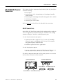
(Catalog Numbers PV300 Micro, PV300,
PV550, PV600, PV900, PV1000, PV1400)
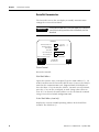
Important User Information
Solid state equipment has operational characteristics differing from those of electromechanical equipment. Safety Guidelines
for the Application, Installation and Maintenance of Solid State Controls (publication SGI-1.1 available from your local
Rockwell Automation sales office or online at http://literature.rockwellautomation.com) describes some important differences
between solid state equipment and hard-wired electromechanical devices. Because of this difference, and also because of the
wide variety of uses for solid state equipment, all persons responsible for applying this equipment must satisfy themselves
that each intended application of this equipment is acceptable.
In no event will Rockwell Automation, Inc. be responsible or liable for indirect or consequential damages resulting from the use or
application of this equipment.
The examples and diagrams in this manual are included solely for illustrative purposes. Because of the many variables and
requirements associated with any particular installation, Rockwell Automation, Inc. cannot assume responsibility or liability
for actual use based on the examples and diagrams.
No patent liability is assumed by Rockwell Automation, Inc. with respect to use of information, circuits, equipment, or
software described in this manual.
Reproduction of the contents of this manual, in whole or in part, without written permission of Rockwell Automation, Inc., is
prohibited.
Throughout this manual, when necessary, we use notes to make you aware of safety considerations.
WARNING
IMPORTANT
ATTENTION
Identifies information about practices or circumstances that can cause an explosion in a
hazardous environment, which may lead to personal injury or death, property damage, or
economic loss.
Identifies information that is critical for successful application and understanding of the product.
Identifies information about practices or circumstances that can lead to personal injury or death,
property damage, or economic loss. Attentions help you identify a hazard, avoid a hazard, and
recognize the consequence
SHOCK HAZARD
Labels may be on or inside the equipment, for example, a drive or motor, to alert people that
dangerous voltage may be present.
BURN HAZARD
Labels may be on or inside the equipment, for example, a drive or motor, to alert people that
surfaces may reach dangerous temperatures.
Allen-Bradley, Rockwell Automation, and TechConnect are trademarks of Rockwell Automation, Inc.
Trademarks not belonging to Rockwell Automation are property of their respective companies.
Summary of Changes
The information below summarizes the changes to this manual since
the last publication.
To help you find new and updated information in this release of the
manual, we have included change bars as shown to the right of this
paragraph.
3Publication 2711-UM014G-EN-P - September 2008
Topic
Page
Updated list of supported memory cards.
105
Added information on the proper placement
of the sealing gasket.
136
143
150
158
167
173
Added information on airborne
contaminants for the PanelView 300
terminal.
235
Added EU Battery Directive to the list of
agency certifications.
248
Added information on battery replacement
and disposal.
271
3
Summary of Changes
4
Publication 2711-UM014G-EN-P - September 2008
Table of Contents
Preface
Objectives. . . . . . . . . . . . . . . . . . . . . .
Intended Audience . . . . . . . . . . . . . . .
Conventions . . . . . . . . . . . . . . . . . . . .
Terminology . . . . . . . . . . . . . . . . . . . .
Installing PanelView Terminals . . . . . .
European Union Directive Compliance
Additional Resources. . . . . . . . . . . . . .
Technical Support . . . . . . . . . . . . . . . .
.
.
.
.
.
.
.
.
.
.
.
.
.
.
.
.
.
.
.
.
.
.
.
.
.
.
.
.
.
.
.
.
.
.
.
.
.
.
.
.
.
.
.
.
.
.
.
.
.
.
.
.
.
.
.
.
.
.
.
.
.
.
.
.
.
.
.
.
.
.
.
.
.
.
.
.
.
.
.
.
.
.
.
.
.
.
.
.
.
.
.
.
.
.
.
.
.
.
.
.
.
.
.
.
.
.
.
.
.
.
.
.
.
.
.
.
.
.
.
.
.
.
.
.
.
.
.
.
15
15
15
15
15
15
16
16
Chapter Objectives . . . . . . . . . . . . . . . . . . . . . . . . . . . . . .
Intended Uses. . . . . . . . . . . . . . . . . . . . . . . . . . . . . . . . . .
Terminal Types . . . . . . . . . . . . . . . . . . . . . . . . . . . . . . . . .
Color and Grayscale Terminals . . . . . . . . . . . . . . . . . . .
PanelView 300 Monochrome Terminals . . . . . . . . . . . .
PanelView 300 Micro Monochrome Terminals . . . . . . . .
PanelView 550 Monochrome Terminals . . . . . . . . . . . .
PanelView 600 Color Terminals . . . . . . . . . . . . . . . . . .
PanelView 900 Monochrome Terminals . . . . . . . . . . . .
PanelView 900 Color Terminals . . . . . . . . . . . . . . . . . .
PanelView 1000 Color Terminals . . . . . . . . . . . . . . . . .
PanelView 1000 Grayscale Terminals . . . . . . . . . . . . . .
PanelView 1400 Color Terminals . . . . . . . . . . . . . . . . .
PanelView 300 Micro Terminal Features . . . . . . . . . . . . . . .
PanelView 300 Micro Terminal Features (front) . . . . . . .
PanelView 300 Micro Terminal Features (back) . . . . . . .
PanelView 300 Terminal Features . . . . . . . . . . . . . . . . . . .
PanelView 300 Terminal Features (front). . . . . . . . . . . .
PanelView 300 Terminal Features (back). . . . . . . . . . . .
PanelView 550 Terminal Features . . . . . . . . . . . . . . . . . . .
PanelView 550 Terminal Features (front). . . . . . . . . . . .
PanelView 550 Keypad or Keypad and Touch Screen
Terminals (back) . . . . . . . . . . . . . . . . . . . . . . . . . . . . .
PanelView 550 Touch Screen Terminal Features (back) .
PanelView 600 Terminal Features . . . . . . . . . . . . . . . . . . .
PanelView 600 Terminal Features (front). . . . . . . . . . . .
PanelView 600 Keypad or Keypad & Touch Screen
Terminal (back) . . . . . . . . . . . . . . . . . . . . . . . . . . . . . .
PanelView 600 Touch Screen Terminal Features (back) .
PanelView 900/1000 Terminal Features . . . . . . . . . . . . . . .
PanelView 900/1000 Terminal Features (front) . . . . . . .
PanelView 900/1000 Terminal Features (back) . . . . . . .
PanelView 1400 Terminal Features. . . . . . . . . . . . . . . . . . .
PanelView 1400 Terminal Features (front) . . . . . . . . . . .
PanelView 1400 Terminal Features (back and sides) . . .
.
.
.
.
.
.
.
.
.
.
.
.
.
.
.
.
.
.
.
.
.
17
17
17
18
18
18
19
20
21
22
23
24
25
26
26
26
27
27
28
29
29
.
.
.
.
30
32
34
34
.
.
.
.
.
.
.
.
36
38
40
40
42
44
44
46
Chapter 1
Terminal Overview
5Publication 2711-UM014G-EN-P - September 2008
5
Table of Contents
Applications . . . . . . . . . . . . . . . . . . . . . . . . . . .
Touch Screen Operation . . . . . . . . . . . . . . .
Keypad Operation . . . . . . . . . . . . . . . . . . . .
Configuration Mode Menu . . . . . . . . . . . . . . . . .
Terminal Messages . . . . . . . . . . . . . . . . . . . . . .
Printing . . . . . . . . . . . . . . . . . . . . . . . . . . . . . .
Alarm List . . . . . . . . . . . . . . . . . . . . . . . . . . . . .
Accessories . . . . . . . . . . . . . . . . . . . . . . . . . . . .
Software . . . . . . . . . . . . . . . . . . . . . . . . . . .
Function Key Legend Kits. . . . . . . . . . . . . . .
Memory Cards and Retainer . . . . . . . . . . . .
Antiglare Overlay. . . . . . . . . . . . . . . . . . . . .
DH-485 Operating and Programming Cables .
PanelView File Transfer Utility . . . . . . . . . . .
Power Supply and Link Couplers . . . . . . . . .
RS-232 Cables . . . . . . . . . . . . . . . . . . . . . . .
Remote I/O or DH+ Cable . . . . . . . . . . . . .
Replacement Parts. . . . . . . . . . . . . . . . . . . . . . .
Backlight Lamps . . . . . . . . . . . . . . . . . . . . .
Real Time Clock Modules. . . . . . . . . . . . . . .
Panel Mount Clips and Studs . . . . . . . . . . . .
Remote I/O Connector . . . . . . . . . . . . . . . . .
Power Input Connector . . . . . . . . . . . . . . . .
.
.
.
.
.
.
.
.
.
.
.
.
.
.
.
.
.
.
.
.
.
.
.
.
.
.
.
.
.
.
.
.
.
.
.
.
.
.
.
.
.
.
.
.
.
.
.
.
.
.
.
.
.
.
.
.
.
.
.
.
.
.
.
.
.
.
.
.
.
.
.
.
.
.
.
.
.
.
.
.
.
.
.
.
.
.
.
.
.
.
.
.
.
.
.
.
.
.
.
.
.
.
.
.
.
.
.
.
.
.
.
.
.
.
.
.
.
.
.
.
.
.
.
.
.
.
.
.
.
.
.
.
.
.
.
.
.
.
.
.
.
.
.
.
.
.
.
.
.
.
.
.
.
.
.
.
.
.
.
.
.
.
.
.
.
.
.
.
.
.
.
.
.
.
.
.
.
.
.
.
.
.
.
.
.
.
.
.
.
.
.
.
.
.
.
.
.
.
.
.
.
.
.
.
.
.
.
48
49
49
50
50
51
51
52
52
52
52
53
53
54
54
55
55
56
56
56
57
57
57
Chapter 2
Applying Power and Resetting
Terminal
Chapter Objectives . . . . . . . . . . . . . .
Wiring and Safety Guidelines. . . . . . .
Hazardous Location Considerations . .
Connect AC Power . . . . . . . . . . . . . .
Connect dc Power. . . . . . . . . . . . . . .
Reset the Terminal . . . . . . . . . . . . . .
Power-up Sequence . . . . . . . . . . . . .
For DH-485 and RS-232 Terminals
For Remote I/O Terminals . . . . . .
.
.
.
.
.
.
.
.
.
.
.
.
.
.
.
.
.
.
.
.
.
.
.
.
.
.
.
.
.
.
.
.
.
.
.
.
.
.
.
.
.
.
.
.
.
.
.
.
.
.
.
.
.
.
.
.
.
.
.
.
.
.
.
.
.
.
.
.
.
.
.
.
.
.
.
.
.
.
.
.
.
.
.
.
.
.
.
.
.
.
.
.
.
.
.
.
.
.
.
.
.
.
.
.
.
.
.
.
.
.
.
.
.
.
.
.
.
.
.
.
.
.
.
.
.
.
.
.
.
.
.
.
.
.
.
.
.
.
.
.
.
.
.
.
.
.
.
.
.
.
.
.
.
59
59
60
61
63
66
67
67
68
.
.
.
.
.
.
.
.
.
.
.
.
.
.
.
.
.
.
.
.
.
.
.
.
.
.
.
.
.
.
.
.
.
.
.
.
.
.
.
.
.
.
.
.
.
.
.
.
.
.
.
.
.
.
.
.
.
.
.
.
.
.
.
.
.
.
.
.
.
.
.
.
.
.
.
.
.
.
.
.
.
.
.
.
.
.
.
.
.
.
.
.
.
.
.
.
.
.
.
.
.
.
.
.
.
.
.
.
.
.
.
.
.
.
.
.
.
.
.
.
.
.
.
.
.
.
.
.
.
.
.
.
.
.
.
.
71
71
72
72
72
73
73
73
Chapter 3
Configuring the Terminal
6
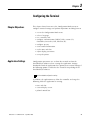
Chapter Objectives . . . . . . . . . . . . . .
Application Settings. . . . . . . . . . . . . .
Access the Configuration Mode Menu
Operations List . . . . . . . . . . . . . .
Language. . . . . . . . . . . . . . . . . . .
Run Mode . . . . . . . . . . . . . . . . . .
Reset Video . . . . . . . . . . . . . . . . .
Comm and Fault Status Indicators.
Publication 2711-UM014G-EN-P - September 2008
Table of Contents
Select a Language . . . . . . . . . . . . . . . . . . . . . . . . . . . . . .
Language List. . . . . . . . . . . . . . . . . . . . . . . . . . . . . . .
Exit . . . . . . . . . . . . . . . . . . . . . . . . . . . . . . . . . . . . . .
Use a Memory Card . . . . . . . . . . . . . . . . . . . . . . . . . . . .
Memory Card Listing . . . . . . . . . . . . . . . . . . . . . . . . .
Disconnect Card . . . . . . . . . . . . . . . . . . . . . . . . . . . .
Applications on Card . . . . . . . . . . . . . . . . . . . . . . . . .
Restore From Card . . . . . . . . . . . . . . . . . . . . . . . . . . .
Save to Card . . . . . . . . . . . . . . . . . . . . . . . . . . . . . . .
Erase/Format Card . . . . . . . . . . . . . . . . . . . . . . . . . . .
Exit . . . . . . . . . . . . . . . . . . . . . . . . . . . . . . . . . . . . . .
Configure Communication . . . . . . . . . . . . . . . . . . . . . . . .
DH-485 Communication . . . . . . . . . . . . . . . . . . . . . . .
DH+ Communication . . . . . . . . . . . . . . . . . . . . . . . . .
Remote I/O Communication. . . . . . . . . . . . . . . . . . . .
ControlNet Communication . . . . . . . . . . . . . . . . . . . .
DeviceNet Communication . . . . . . . . . . . . . . . . . . . . .
DF1 Communication . . . . . . . . . . . . . . . . . . . . . . . . .
EtherNet/IP Communication . . . . . . . . . . . . . . . . . . . .
Configure Presets . . . . . . . . . . . . . . . . . . . . . . . . . . . . . .
Power-up with Presets or Last States . . . . . . . . . . . . . .
Restart Unit and Load Values . . . . . . . . . . . . . . . . . . .
Key Repeat Rate . . . . . . . . . . . . . . . . . . . . . . . . . . . .
Key Repeat Delay . . . . . . . . . . . . . . . . . . . . . . . . . . .
Exit . . . . . . . . . . . . . . . . . . . . . . . . . . . . . . . . . . . . . .
Viewing Terminal Information . . . . . . . . . . . . . . . . . . . . .
Boot . . . . . . . . . . . . . . . . . . . . . . . . . . . . . . . . . . . . .
Firmware. . . . . . . . . . . . . . . . . . . . . . . . . . . . . . . . . .
Hardware . . . . . . . . . . . . . . . . . . . . . . . . . . . . . . . . .
Filename . . . . . . . . . . . . . . . . . . . . . . . . . . . . . . . . . .
Font File . . . . . . . . . . . . . . . . . . . . . . . . . . . . . . . . . .
Exit . . . . . . . . . . . . . . . . . . . . . . . . . . . . . . . . . . . . . .
Adjust Screen Parameters. . . . . . . . . . . . . . . . . . . . . . . . .
PanelView 300 Micro Terminal Screen Setup . . . . . . . .
PanelView 300 Terminal Screen Setup . . . . . . . . . . . .
PanelView 550 Terminal Screen Setup . . . . . . . . . . . .
PanelView 600/900/1000 Color Terminal Screen Setup
PanelView 900 Monochrome Terminal Screen Setup . .
PanelView 1000 Grayscale Terminal Screen Setup . . . .
PanelView 1400 Color Terminal Screen Setup . . . . . . .
Set the Time and Date. . . . . . . . . . . . . . . . . . . . . . . . . . .
Set the Time . . . . . . . . . . . . . . . . . . . . . . . . . . . . . . .
Set the Date. . . . . . . . . . . . . . . . . . . . . . . . . . . . . . . .
Exit . . . . . . . . . . . . . . . . . . . . . . . . . . . . . . . . . . . . . .
Publication 2711-UM014G-EN-P - September 2008
.
.
.
.
.
.
.
.
.
.
.
.
.
.
.
.
.
.
.
.
.
.
.
.
.
.
.
.
.
.
.
.
.
.
.
.
.
.
.
.
.
.
.
.
.
.
.
.
.
.
.
.
.
.
.
.
.
.
.
.
.
.
.
.
.
.
.
.
.
.
.
.
.
.
.
.
.
.
.
.
.
.
.
.
73
74
74
74
74
74
74
75
75
75
75
75
75
77
78
79
82
84
86
88
88
88
89
89
89
89
89
89
89
90
90
90
90
90
91
93
94
95
97
98
100
101
101
101
7
Table of Contents
Set Up the Printer . . . . . . . . . .
Handshaking . . . . . . . . . . .
Communication Parameters
Baud Rate . . . . . . . . . . . . .
Top of Form . . . . . . . . . . .
Port Mode . . . . . . . . . . . . .
Exit . . . . . . . . . . . . . . . . . .
.
.
.
.
.
.
.
.
.
.
.
.
.
.
.
.
.
.
.
.
.
.
.
.
.
.
.
.
.
.
.
.
.
.
.
.
.
.
.
.
.
.
.
.
.
.
.
.
.
.
.
.
.
.
.
.
.
.
.
.
.
.
.
.
.
.
.
.
.
.
.
.
.
.
.
.
.
.
.
.
.
.
.
.
.
.
.
.
.
.
.
.
.
.
.
.
.
.
.
.
.
.
.
.
.
.
.
.
.
.
.
.
.
.
.
.
.
.
.
.
.
.
.
.
.
.
.
.
.
.
.
.
.
.
.
.
.
.
.
.
.
.
.
.
.
.
.
102
102
102
103
103
103
103
Chapter Objectives . . . . . . . . . . . . . . .
Supported Memory Cards . . . . . . . . . .
Use the Memory Card Retainer . . . . . .
Load Application from a Memory Card.
Load Application on a Memory Card . .
Store Font Files on a Memory Card . . .
Remove a Memory Card . . . . . . . . . . .
.
.
.
.
.
.
.
.
.
.
.
.
.
.
.
.
.
.
.
.
.
.
.
.
.
.
.
.
.
.
.
.
.
.
.
.
.
.
.
.
.
.
.
.
.
.
.
.
.
.
.
.
.
.
.
.
.
.
.
.
.
.
.
.
.
.
.
.
.
.
.
.
.
.
.
.
.
.
.
.
.
.
.
.
.
.
.
.
.
.
.
.
.
.
.
.
.
.
.
.
.
.
.
.
.
105
105
106
108
110
111
112
Chapter Objectives . . . . . . . . . . . . . . . . . . . . . . . . . . . . . .
Application Information. . . . . . . . . . . . . . . . . . . . . . . . . . .
Important Information for PanelView 300 Micro Terminal
Operations . . . . . . . . . . . . . . . . . . . . . . . . . . . . . . . . . . . .
Screen Security . . . . . . . . . . . . . . . . . . . . . . . . . . . . . . . . .
Push Button Operation . . . . . . . . . . . . . . . . . . . . . . . . . . .
Control Lists . . . . . . . . . . . . . . . . . . . . . . . . . . . . . . . . . . .
Active List Item . . . . . . . . . . . . . . . . . . . . . . . . . . . . . .
Active Control List . . . . . . . . . . . . . . . . . . . . . . . . . . . .
Cursor . . . . . . . . . . . . . . . . . . . . . . . . . . . . . . . . . . . . .
List Keys . . . . . . . . . . . . . . . . . . . . . . . . . . . . . . . . . . .
Cursor-piloted Control Lists . . . . . . . . . . . . . . . . . . . . .
Numeric Entry Cursor Point . . . . . . . . . . . . . . . . . . . . .
Keypad Enable Button . . . . . . . . . . . . . . . . . . . . . . . . .
Scratchpad. . . . . . . . . . . . . . . . . . . . . . . . . . . . . . . . . .
ASCII Entry Controls . . . . . . . . . . . . . . . . . . . . . . . . . . . . .
ASCII Scratchpad - Keypad or Keypad/Touch Screen
Terminals . . . . . . . . . . . . . . . . . . . . . . . . . . . . . . . . . .
ASCII Scratchpad - PV300 Micro/300 Terminals . . . . . . .
ASCII Scratchpad - PV550/600 Touch Screen Terminals .
ASCII Scratchpad - PV900/1000/1400 Touch Screen
Terminals . . . . . . . . . . . . . . . . . . . . . . . . . . . . . . . . . .
ASCII Scratchpads in Other Languages . . . . . . . . . . . . .
Screen Selectors . . . . . . . . . . . . . . . . . . . . . . . . . . . . . . . .
Cursor Operation . . . . . . . . . . . . . . . . . . . . . . . . . . . . .
List Keys . . . . . . . . . . . . . . . . . . . . . . . . . . . . . . . . . . .
List Indicators . . . . . . . . . . . . . . . . . . . . . . . . . . . . . . . . . .
113
113
Chapter 4
Using a Memory Card
Chapter 5
Running Applications
8
113
114
114
115
115
116
116
117
117
118
118
119
121
121
122
123
124
125
126
127
127
128
Publication 2711-UM014G-EN-P - September 2008
Table of Contents
Multistate Indicators . .
Bar Graph Displays . . .
Analog Gauges . . . . . .
Numeric Data Displays
Message Displays . . . .
Time or Date . . . . . . .
Printing . . . . . . . . . . .
Alarms . . . . . . . . . . . .
.
.
.
.
.
.
.
.
.
.
.
.
.
.
.
.
.
.
.
.
.
.
.
.
.
.
.
.
.
.
.
.
.
.
.
.
.
.
.
.
.
.
.
.
.
.
.
.
.
.
.
.
.
.
.
.
.
.
.
.
.
.
.
.
.
.
.
.
.
.
.
.
.
.
.
.
.
.
.
.
.
.
.
.
.
.
.
.
.
.
.
.
.
.
.
.
.
.
.
.
.
.
.
.
.
.
.
.
.
.
.
.
.
.
.
.
.
.
.
.
.
.
.
.
.
.
.
.
.
.
.
.
.
.
.
.
.
.
.
.
.
.
.
.
.
.
.
.
.
.
.
.
.
.
.
.
.
.
.
.
.
.
.
.
.
.
.
.
.
.
.
.
.
.
.
.
.
.
.
.
.
.
.
.
.
.
.
.
.
.
.
.
.
.
.
.
.
.
.
.
.
.
.
.
.
.
.
.
.
.
.
.
.
.
.
.
128
128
129
129
129
130
130
131
Chapter Objectives . . . . . . . . . . . . .
Hazardous Location Considerations .
Enclosures . . . . . . . . . . . . . . . . . . .
Required Tools . . . . . . . . . . . . . . . .
Mounting Dimensions . . . . . . . . . . .
Cutout Dimensions . . . . . . . . . . . . .
Clearances . . . . . . . . . . . . . . . . . . .
Install Terminal in Panel . . . . . . . . .
.
.
.
.
.
.
.
.
.
.
.
.
.
.
.
.
.
.
.
.
.
.
.
.
.
.
.
.
.
.
.
.
.
.
.
.
.
.
.
.
.
.
.
.
.
.
.
.
.
.
.
.
.
.
.
.
.
.
.
.
.
.
.
.
.
.
.
.
.
.
.
.
.
.
.
.
.
.
.
.
.
.
.
.
.
.
.
.
.
.
.
.
.
.
.
.
.
.
.
.
.
.
.
.
.
.
.
.
.
.
.
.
.
.
.
.
.
.
.
.
.
.
.
.
.
.
.
.
.
.
.
.
.
.
.
.
133
133
134
134
134
135
135
136
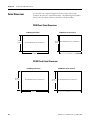
Chapter Objectives . . . . . . . . . . . . . .
Hazardous Location Considerations . .
Enclosures . . . . . . . . . . . . . . . . . . . .
Required Tools . . . . . . . . . . . . . . . . .
Mounting Dimensions . . . . . . . . . . . .
Cutout Dimensions . . . . . . . . . . . . . .
Clearances . . . . . . . . . . . . . . . . . . . .
Install the PV300 Terminal in a Panel.
.
.
.
.
.
.
.
.
.
.
.
.
.
.
.
.
.
.
.
.
.
.
.
.
.
.
.
.
.
.
.
.
.
.
.
.
.
.
.
.
.
.
.
.
.
.
.
.
.
.
.
.
.
.
.
.
.
.
.
.
.
.
.
.
.
.
.
.
.
.
.
.
.
.
.
.
.
.
.
.
.
.
.
.
.
.
.
.
.
.
.
.
.
.
.
.
.
.
.
.
.
.
.
.
.
.
.
.
.
.
.
.
.
.
.
.
.
.
.
.
.
.
.
.
.
.
.
.
139
139
140
140
141
141
142
143
Chapter Objectives . . . . . . . . . . . . . . . . . . . . . . . . . . . .
Hazardous Location Considerations . . . . . . . . . . . . . . . .
Enclosures . . . . . . . . . . . . . . . . . . . . . . . . . . . . . . . . . .
Required Tools . . . . . . . . . . . . . . . . . . . . . . . . . . . . . . .
Mounting Dimensions . . . . . . . . . . . . . . . . . . . . . . . . . .
PV550 Keypad, Keypad & Touch Screen Terminals . .
PV550 Touch Screen Terminals. . . . . . . . . . . . . . . . .
Clearances . . . . . . . . . . . . . . . . . . . . . . . . . . . . . . . . . .
Cutout Dimensions . . . . . . . . . . . . . . . . . . . . . . . . . . . .
PV550 Keypad, Keypad and Touch Screen Terminals
PV550 Touch Screen Terminals. . . . . . . . . . . . . . . . .
Install the PV550 Terminal in a Panel. . . . . . . . . . . . . . .
.
.
.
.
.
.
.
.
.
.
.
.
.
.
.
.
.
.
.
.
.
.
.
.
145
145
146
147
147
147
147
148
149
149
149
150
Chapter 6
Installing the PV300 Micro
Terminal
Chapter 7
Installing the PV300 Terminal
Chapter 8
Installing the PV550 Terminal
Publication 2711-UM014G-EN-P - September 2008
9
Table of Contents
Chapter 9
Installing the PV600 Terminal
Chapter Objectives . . . . . . . . . . . . . . . . . . . . . . . . . . . .
Hazardous Location Considerations . . . . . . . . . . . . . . . .
Enclosures . . . . . . . . . . . . . . . . . . . . . . . . . . . . . . . . . .
Required Tools . . . . . . . . . . . . . . . . . . . . . . . . . . . . . . .
Mounting Dimensions . . . . . . . . . . . . . . . . . . . . . . . . . .
PV600 Keypad, Keypad and Touch Screen Terminals
PV600 Touch Screen Terminals. . . . . . . . . . . . . . . . .
Cutout Dimensions . . . . . . . . . . . . . . . . . . . . . . . . . . . .
PV600 Keypad, Keypad and Touch Screen Terminals
PV600 Touch Screen Terminals. . . . . . . . . . . . . . . . .
Clearances . . . . . . . . . . . . . . . . . . . . . . . . . . . . . . . . . .
PV600 Keypad and Keypad and Touch Screen
Terminals . . . . . . . . . . . . . . . . . . . . . . . . . . . . . . . .
PV600 Touch Screen Terminals. . . . . . . . . . . . . . . . .
Install the PV600 in a Panel . . . . . . . . . . . . . . . . . . . . . .
.
.
.
.
.
.
.
.
.
.
.
.
.
.
.
.
.
.
.
.
.
.
153
153
154
154
155
155
155
156
156
156
157
. . 157
. . 157
. . 158
Chapter 10
Installing the PV900/1000
Terminals
Chapter Objectives . . . . . . . . . . . . . . . . . . . . . . . . .
Hazardous Location Considerations . . . . . . . . . . . . .
Enclosures . . . . . . . . . . . . . . . . . . . . . . . . . . . . . . .
Required Tools . . . . . . . . . . . . . . . . . . . . . . . . . . . .
PV900 Terminals Mounting Dimensions . . . . . . . . . .
PV900 Touch Terminal Mounting Dimensions . . .
PV900 Keypad Terminal Mounting Dimensions . .
PV1000 Terminals Mounting Dimensions . . . . . . . . .
PV1000 Touch Terminal Mounting Dimensions . .
PV1000 Keypad Terminal Mounting Dimensions .
Clearances . . . . . . . . . . . . . . . . . . . . . . . . . . . . . . .
Cutout Dimensions . . . . . . . . . . . . . . . . . . . . . . . . .
PV900 Panel Cutout Dimensions. . . . . . . . . . . . .
PV1000 Panel Cutout Dimensions . . . . . . . . . . . .
Install the PV900/PV1000 Terminals in a Panel . . . . .
.
.
.
.
.
.
.
.
.
.
.
.
.
.
.
.
.
.
.
.
.
.
.
.
.
.
.
.
.
.
.
.
.
.
.
.
.
.
.
.
.
.
.
.
.
.
.
.
.
.
.
.
.
.
.
.
.
.
.
.
.
.
.
.
.
.
.
.
.
.
.
.
.
.
.
161
161
162
162
163
163
163
164
164
164
165
166
166
166
167
.
.
.
.
.
.
.
.
.
.
.
.
.
.
.
.
.
.
.
.
.
.
.
.
.
.
.
.
.
.
.
.
.
.
.
.
.
.
.
.
.
.
.
.
.
.
.
.
.
.
169
169
169
170
170
170
171
172
172
172
Chapter 11
Installing the PV1400 Terminal
10
Chapter Objectives . . . . . . . . . . . . . . . . . . . . . . . . .
Enclosures . . . . . . . . . . . . . . . . . . . . . . . . . . . . . . .
Required Tools . . . . . . . . . . . . . . . . . . . . . . . . . . . .
Mounting Dimensions . . . . . . . . . . . . . . . . . . . . . . .
PV1400 Touch Terminal Mounting Dimensions . .
PV1400 Keypad Terminal Mounting Dimensions .
Clearances . . . . . . . . . . . . . . . . . . . . . . . . . . . . . . .
Cutout Dimensions . . . . . . . . . . . . . . . . . . . . . . . . .
PV1400 Keypad Terminals . . . . . . . . . . . . . . . . .
PV1400 Touch Screen Terminals. . . . . . . . . . . . .
Publication 2711-UM014G-EN-P - September 2008
Table of Contents
Install the PV1400 Terminal in a Panel . . . . . . . . . . . . . . . . 173
Mount Terminal with Mounting Studs . . . . . . . . . . . . . . 175
Chapter 12
Terminal Connections
Publication 2711-UM014G-EN-P - September 2008
Chapter Objectives . . . . . . . . . . . . . . . . . . . . . . . . . . . . . .
Wiring and Safety Guidelines. . . . . . . . . . . . . . . . . . . . . . .
Cable Charts . . . . . . . . . . . . . . . . . . . . . . . . . . . . . . . . . . .
Runtime Communication Cables - to Processors . . . . . .
Runtime Communication Cables - to Network Interface
Module . . . . . . . . . . . . . . . . . . . . . . . . . . . . . . . . . . . .
Application File Upload/Download (Direct) Cables . . . .
Remote I/O Terminal Connections. . . . . . . . . . . . . . . . . . .
Remote I/O Terminal Ports. . . . . . . . . . . . . . . . . . . . . .
Supported Controllers . . . . . . . . . . . . . . . . . . . . . . . . .
Making Remote I/O Connections . . . . . . . . . . . . . . . . .
Remote I/O Pass-through using DH+ . . . . . . . . . . . . . .
DH+ Terminal Connections . . . . . . . . . . . . . . . . . . . . . . . .
DH+ Terminal Ports . . . . . . . . . . . . . . . . . . . . . . . . . . .
Typical DH+ System Configuration . . . . . . . . . . . . . . . .
Making DH+ Connections . . . . . . . . . . . . . . . . . . . . . .
DH-485 Terminal Connections . . . . . . . . . . . . . . . . . . . . . .
DH-485 Terminal Ports (RJ45). . . . . . . . . . . . . . . . . . . .
Connecting to a Single SLC Controller (Point-to-point). .
Connecting to a DH-485 Network. . . . . . . . . . . . . . . . .
Connecting a Computer . . . . . . . . . . . . . . . . . . . . . . . .
Connecting a Hand-held Terminal . . . . . . . . . . . . . . . .
RS-232 (DH-485) Terminal Connections . . . . . . . . . . . . . . .
RS-232 Terminal Ports . . . . . . . . . . . . . . . . . . . . . . . . .
Connecting to an SLC, CompactLogix, MicroLogix
Controller (Point-to-point) . . . . . . . . . . . . . . . . . . . . . .
Connecting to a MicroLogix Controller through an
AIC+ Module . . . . . . . . . . . . . . . . . . . . . . . . . . . . . . . .
Connecting a Computer . . . . . . . . . . . . . . . . . . . . . . . .
Connecting a DH+ to DH-485 Pass-through Link . . . . . .
RS-232 (DF1) Terminal Connections. . . . . . . . . . . . . . . . . .
Compatible Controllers. . . . . . . . . . . . . . . . . . . . . . . . .
RS-232 (DF1) Terminal Ports. . . . . . . . . . . . . . . . . . . . .
RS-232/DF1 Port Connector . . . . . . . . . . . . . . . . . . . . .
Connecting to a MicroLogix 1000 Controller . . . . . . . . .
Connecting to an SLC, PLC, or MicroLogix 1500LRP
Controller . . . . . . . . . . . . . . . . . . . . . . . . . . . . . . . . . .
Connecting to a CompactLogix or FlexLogix . . . . . . . . .
Using a Modem . . . . . . . . . . . . . . . . . . . . . . . . . . . . . .
Connecting to a DeviceNet or EtherNet/IP Network . . .
Constructing a Null Modem Cable . . . . . . . . . . . . . . . .
177
177
178
178
183
184
185
185
186
187
188
189
189
190
191
192
192
193
194
196
198
199
199
200
201
201
202
202
203
203
204
204
205
205
206
206
207
11
Table of Contents
ControlNet Connections . . . . . . . . . . . . . . . . . . . . . . . . . .
Related Information . . . . . . . . . . . . . . . . . . . . . . . . . . .
ControlNet Protocol . . . . . . . . . . . . . . . . . . . . . . . . . . .
Compatible ControlNet Controllers . . . . . . . . . . . . . . . .
ControlNet Terminal Ports . . . . . . . . . . . . . . . . . . . . . .
Typical ControlNet Network . . . . . . . . . . . . . . . . . . . . .
Making ControlNet Connections . . . . . . . . . . . . . . . . . .
NAP and Redundant Cables . . . . . . . . . . . . . . . . . . . . .
DeviceNet Network Terminal Connections . . . . . . . . . . . . .
DeviceNet Terminal Ports. . . . . . . . . . . . . . . . . . . . . . .
Making DeviceNet Connections . . . . . . . . . . . . . . . . . .
Typical DeviceNet Network . . . . . . . . . . . . . . . . . . . . .
EtherNet/IP Connections . . . . . . . . . . . . . . . . . . . . . . . . .
EtherNet/IP Terminal Ports . . . . . . . . . . . . . . . . . . . . . .
Ethernet Connector . . . . . . . . . . . . . . . . . . . . . . . . . . .
Cables . . . . . . . . . . . . . . . . . . . . . . . . . . . . . . . . . . . . .
Typical EtherNet/IP Configuration . . . . . . . . . . . . . . . .
PanelView 300 Micro Terminal Connections . . . . . . . . . . . .
RS-232 Communication Port . . . . . . . . . . . . . . . . . . . . .
Connecting to a MicroLogix Controller . . . . . . . . . . . . .
Connecting to an SLC, PLC-5, ControlLogix, MicroLogix
1500LRP, CompactLogix, or FlexLogix. . . . . . . . . . . . . .
Connecting to an Advanced Interface Converter . . . . . .
Connecting to a DeviceNet Interface (DNI) . . . . . . . . . .
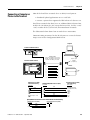
Connecting to a Personal Computer (Application File
Transfers) . . . . . . . . . . . . . . . . . . . . . . . . . . . . . . . . . .
Connecting a Computer or Printer to the Terminal . . . . . . .
207
207
208
208
208
209
210
211
212
212
213
214
215
215
216
216
217
218
218
218
219
220
220
221
223
Chapter 13
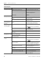
Troubleshooting and Maintenance Chapter Objectives . . . . . . . . . . . . . . . . . . . . . . . . . . . . . . 225
Equipment Required . . . . . . . .
Use the Troubleshooting Chart
Interpret Status Indicators . . . .
Clean the Display Window . . .
Remove Paint and Grease .
Equipment Hose-downs . . .
Replace the Clock Module . . . .
Replace the Backlight . . . . . . .
.
.
.
.
.
.
.
.
.
.
.
.
.
.
.
.
.
.
.
.
.
.
.
.
.
.
.
.
.
.
.
.
.
.
.
.
.
.
.
.
.
.
.
.
.
.
.
.
.
.
.
.
.
.
.
.
.
.
.
.
.
.
.
.
.
.
.
.
.
.
.
.
.
.
.
.
.
.
.
.
.
.
.
.
.
.
.
.
.
.
.
.
.
.
.
.
.
.
.
.
.
.
.
.
.
.
.
.
.
.
.
.
.
.
.
.
.
.
.
.
.
.
.
.
.
.
.
.
.
.
.
.
.
.
.
.
.
.
.
.
.
.
.
.
.
.
.
.
.
.
.
.
.
.
.
.
.
.
.
.
.
.
.
.
.
.
.
.
225
225
229
231
231
231
232
232
Micro Terminal . . . . . . . . . . . . . . .
Terminal . . . . . . . . . . . . . . . . . . . .
Terminals . . . . . . . . . . . . . . . . . . .
Color Keypad and Touch Terminals
Color Touch Only Terminals . . . .
.
.
.
.
.
.
.
.
.
.
.
.
.
.
.
.
.
.
.
.
.
.
.
.
.
.
.
.
.
.
233
234
236
238
239
Appendix A
Specifications
12
PanelView
PanelView
PanelView
PanelView
PanelView
300
300
550
600
600
Publication 2711-UM014G-EN-P - September 2008
Table of Contents
PanelView 900 Monochrome and Color Terminals
PanelView 1000 Color & Grayscale . . . . . . . . . . .
PanelView 1400 Color . . . . . . . . . . . . . . . . . . . . .
Communication. . . . . . . . . . . . . . . . . . . . . . . . . .
Agency Certifications. . . . . . . . . . . . . . . . . . . . . .
.
.
.
.
.
.
.
.
.
.
.
.
.
.
.
.
.
.
.
.
.
.
.
.
.
.
.
.
.
.
.
.
.
.
.
240
244
245
247
248
Appendix B
Messages, Codes and Self-test
Numbers
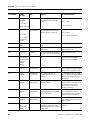
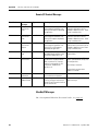
Types of Terminal Messages . . . . .
Status Messages . . . . . . . . . . . .
Reminder Messages . . . . . . . . .
Warning Messages . . . . . . . . . .
Fault Messages. . . . . . . . . . . . .
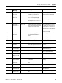
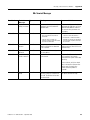
General Terminal Messages . . . . . .
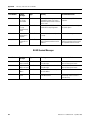
DH-485 Terminal Messages . . .
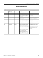
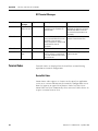
ControlNet Terminal Messages .
Remote I/O Terminal Messages
EtherNet/IP Messages. . . . . . . .
DH+ Terminal Messages. . . . . .
DF1 Terminal Messages . . . . . .
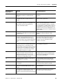
Terminal Codes. . . . . . . . . . . . . . .
DeviceNet Codes . . . . . . . . . . .
General Codes . . . . . . . . . . . . .
ControlNet Codes. . . . . . . . . . .
EtherNet/IP Codes . . . . . . . . . .
Remote I/O Communication Loss. .
Self-test Numbers . . . . . . . . . . . . .
.
.
.
.
.
.
.
.
.
.
.
.
.
.
.
.
.
.
.
.
.
.
.
.
.
.
.
.
.
.
.
.
.
.
.
.
.
.
.
.
.
.
.
.
.
.
.
.
.
.
.
.
.
.
.
.
.
.
.
.
.
.
.
.
.
.
.
.
.
.
.
.
.
.
.
.
.
.
.
.
.
.
.
.
.
.
.
.
.
.
.
.
.
.
.
.
.
.
.
.
.
.
.
.
.
.
.
.
.
.
.
.
.
.
.
.
.
.
.
.
.
.
.
.
.
.
.
.
.
.
.
.
.
.
.
.
.
.
.
.
.
.
.
.
.
.
.
.
.
.
.
.
.
.
.
.
.
.
.
.
.
.
.
.
.
.
.
.
.
.
.
.
.
.
.
.
.
.
.
.
.
.
.
.
.
.
.
.
.
.
.
.
.
.
.
.
.
.
.
.
.
.
.
.
.
.
.
.
.
.
.
.
.
.
.
.
.
.
.
.
.
.
.
.
.
.
.
.
.
.
.
.
.
.
.
.
.
.
.
.
.
.
.
.
.
.
.
.
.
.
.
.
.
.
.
.
.
.
.
.
.
.
.
.
.
.
.
.
.
.
.
.
.
.
.
.
.
.
.
.
.
.
.
.
.
.
.
.
.
.
.
.
.
.
.
.
.
.
.
.
.
.
.
.
.
.
.
.
.
.
.
.
.
.
.
.
.
.
.
.
.
.
.
.
.
.
.
.
.
.
.
.
.
.
.
.
.
.
.
.
.
.
249
249
249
249
249
250
254
255
256
256
257
258
258
258
262
262
263
267
267
EMC and Low Voltage Directives .
Intended Use of Product . . . . . . .
Wiring Recommendations. . . . . . .
Declarations of Conformity. . . . . .
Battery Replacement and Disposal
.
.
.
.
.
.
.
.
.
.
.
.
.
.
.
.
.
.
.
.
.
.
.
.
.
.
.
.
.
.
.
.
.
.
.
.
.
.
.
.
.
.
.
.
.
.
.
.
.
.
.
.
.
.
.
.
.
.
.
.
.
.
.
.
.
.
.
.
.
.
.
.
.
.
.
.
.
.
.
.
269
270
270
270
271
Appendix C
European Union Directive
Compliance
Glossary
Index
Publication 2711-UM014G-EN-P - September 2008
13
Table of Contents
14
Publication 2711-UM014G-EN-P - September 2008
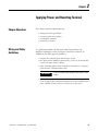
Preface
Objectives
Read this preface to familiarize yourself with the rest of this manual.
•
•
•
•
•
•
•
Intended Audience
Intended audience
Conventions used
Terminology
Installing PanelView terminals
European Union Directive Compliance
Related publications
Technical support
No special knowledge is required to understand this manual or
operate the PanelView terminals. Before running an application, you
must know the functions of all screens and screen objects. This
information is available from the application designer.
Equipment installers must be familiar with standard panel installation
techniques.
Conventions
The manual uses these conventions:
• For specific PanelView terminals, PanelView is replaced with the
PV abbreviation. For example: PV1000 refers to the PanelView
1000 terminal.
• PanelView terminal refers to any one of the PanelView
terminals.
Terminology
This manual contains some terms that may be unfamiliar.
Use the Glossary on page 273 of this manual for assistance.
Installing PanelView
Terminals
Each terminal is shipped with installation instructions and a panel
cutout. Please follow these instructions when installing your
PanelView terminal in a panel or enclosure.
European Union Directive
Compliance
Refer to Appendix C for details on installing the PanelView terminals
in industrial environments requiring compliance with European Union
Directives.
15Publication 2711-UM014G-EN-P - September 2008
15
Preface
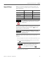
Additional Resources
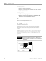
Refer to the extensive online help for the PanelBuilder32 Software or
the following publications if necessary.
Resource
Description
PanelBuilder32 Software Getting Results
Manual, publication 2711-GR003
Information about using PanelBuilder32
software
PanelBuilder32 Quick Start Manual,
publication 2711-QS003
Information about starting PanelBuilder32
software
WinPFT File Transfer Utility, publication
2711-TD006
Information about the WinPFT file transfer
utility
PROFIBUS DP Communication for
PanelView Terminals, publication 2711-6.3
Information about PROFIBUS DP
communication for PanelView terminals
Modbus Communication for PanelView
Terminals, publication 2711-6.9
Information about Modbus communication
for PanelView terminals
Programmable Controller Wiring and
Grounding Guidelines, publication 1770-4.1
Information on wiring and grounding
Data Highway/Data Highway Plus/Data
Highway-485 Cable Installation Manual,
publication 1770-6.2.2
Information about installing Data
Highway/Data Highway Plus/Data
Highway-485 cable
For information relating to your controller, refer to the appropriate
manual.
Technical Support
If you have questions about the PanelView terminals or the
PanelBuilder32 software, please refer to the online manuals or online
help provided with the PanelBuilder32 installation CD. These
publications are also available from the literature library at:
http://literature.rockwellautomation.com
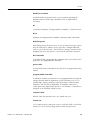
Frequently Asked Questions
Documents on frequently asked questions are available at:
http://www.rockwellautomation.com/knowledgebase
Software and Firmware Upgrades
To receive software updates (software serial number required) and
firmware upgrades for your PanelView terminal:
• locate on PanelBuilder32 installation CD.
• call Rockwell Software at 1-440-646-7700 or fax 1-440-646-7701.
• access www.software.rockwell.com.
16
Publication 2711-UM014G-EN-P - September 2008
Chapter
1
Terminal Overview
Chapter Objectives
This chapter gives an overview of the PanelView Operator Terminals.
• Intended uses
• Terminal types and features
• Applications
• Configuration mode
• Terminal messages
• Printing
• Accessories and replacement parts
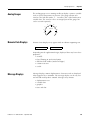
Intended Uses
You can use the PanelView operator terminals for a wide variety of
machine control and monitoring applications.
ATTENTION
Terminal Types
Do not use a PanelView terminal for emergency stops or other
controls critical to the safety of personnel or equipment. Use
separate hardwired operator interface devices that do not
depend on solid state electronics. See the inside front cover of
this manual for guidelines.
PanelView terminals are available in a variety of options.
• Display size and type (monochrome, grayscale, color)
• Operator input (touch screen or keypad)
• Communication port (DH-485, RS-232, remote I/O, DH+,
ControlNet, DeviceNet, Ethernet, EtherNet/IP, DF1)
• RS-232 printer port support
In addition, some terminals are available with:
• AC or DC power (L1 at the end of a catalog number indicates a
DC terminal, for example, 2711-B5A1L1, or -T9C1L1).
• stainless steel bezel available on PanelView 550 keypad or
keypad & touch terminals.
Contact your Allen-Bradley representative for availability.
17Publication 2711-UM014G-EN-P - September 2008
17
Chapter 1
Terminal Overview
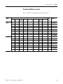
Color and Grayscale Terminals
Color terminals support a fixed palette of 32 standard EGA colors.
Grayscale terminals support a fixed palette of four colors (shades of
gray). All color in an application is defined when the application is
created. Colors are not selectable at the terminal.
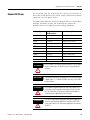
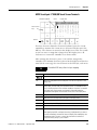
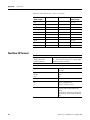
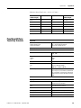
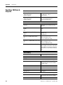
PanelView 300 Monochrome Terminals
The PanelView 300 terminal is only available with 24V DC input
power.
Operator
Input
Communication Port
Keypad
x
DH-485
RS-232
DeviceNet
(DH-485)
RS-232
(DF1)
Printer Port
RS-232
Catalog
Number
2711-K3A2L1
x
2711-K3A5L1
x
x
x
2711-K3A10L1
2711-K3A17L1
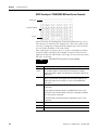
PanelView 300 Micro Monochrome Terminals
The PanelView 300 Micro terminal is available only with 24V DC input
power and does not have a printer port. The PV300 Micro terminal
contains a single RS-232 communication port which supports either
DF1 or DH485 communication protocols as specified in the table
below.
Operator
Input
Communication Port
Keypad
x
DH-485
DF1
2711-M3A19L1
x
18
Catalog
Number
2711-M3A18L1
Publication 2711-UM014G-EN-P - September 2008
Terminal Overview
Chapter 1
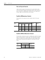
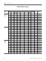
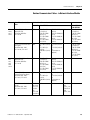
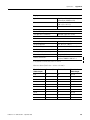
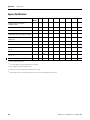
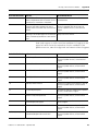
PanelView 550 Monochrome Terminals
The touch screen version of the PanelView 550 terminal is available
only with 24V DC power. The L1 in the catalog number indicates DC
power.
Operator
Input
Touch
Screen and
Keypad
Communication Port
RIO DH-485 RS-232
DH+
(DH-485)
x
x
x
x
x
x
DeviceNet ControlNet RS-232 Ethernet
(DF1)
Catalog
Number(1)
x
2711-B5A1
2711-B5A2
2711-B5A3
2711-B5A5
2711-B5A8
2711-B5A9
2711-B5A10
2711-B5A15
2711-B5A16
2711-B5A20
2711-K5A1
2711-K5A2
2711-K5A3
2711-K5A5
2711-K5A8
2711-K5A9
2711-K5A10
2711-K5A15
2711-K5A16
2711-K5A20
2711-T5A1L1
2711-T5A2L1
2711-T5A3L1
2711-T5A5L1
2711-T5A8L1
2711-T5A9L1
2711-T5A10L1
2711-T5A15L1
2711-T5A16L1
2711-T5A20L1
x
x
x
x
x
Keypad
Printer
Port
RS-232
x
x
x
x
x
x
x
x
x
x
x
x
x
x
x
x
x
x
Touch
Screen
(24V DC
only)
x
x
x
x
x
x
x
x
x
x
x
(1)
x
x
x
x
x
x
x
x
x
x
x
x
x
Add L1 to the end of the catalog number for 24V DC power.
Add L2 to the end of a catalog number for stainless steel. Not available for the touch screen terminals.
Add L3 to the end of a catalog number for 24V DC power and stainless steel. Stainless steel is not available for the touch screen terminals.
Publication 2711-UM014G-EN-P - September 2008
19
Chapter 1
Terminal Overview
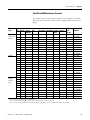
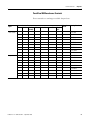
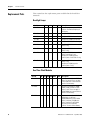
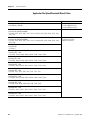
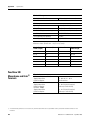
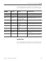
PanelView 600 Color Terminals
Operator
Input
Touch
Screen and
Keypad
Communication Port
RIO
DH-485
RS-232 DH+
(DH-485)
DeviceNet ControlNet
RS-232 Ethernet
(DF1)
x
Printer
Port
RS-232
Catalog
Number(1)
x
2711-B6C1
x
2711-B6C2
x
x
x
2711-B6C5
x
x
x
x
x
x
Keypad
x
x
2711-B6C8
x
2711-B6C9
x
2711-B6C10
x
2711-B6C15
x
2711-B6C16
x
2711-B6C20
x
2711-K6C1
x
2711-K6C2
x
x
x
x
x
x
x
x
x
x
2711-K6C8
x
2711-K6C9
x
2711-K6C10
x
2711-K6C15
x
2711-K6C16
x
2711-K6C20
x
2711-T6C1L1
x
2711-T6C2L1
x
x
x
x
x
x
x
x
20
2711-T6C3L1
2711-T6C5L1
x
(1)
2711-K6C3
2711-K6C5
x
Touch
Screen
(24V DC
only)
2711-B6C3
x
2711-T6C8L1
x
2711-T6C9L1
x
2711-T6C10L1
x
2711-T6C15L1
x
2711-T6C16L1
x
2711-T6C20L1
Add L1 to the end of the catalog number for 24V DC power.
Publication 2711-UM014G-EN-P - September 2008
Terminal Overview
Chapter 1
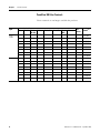
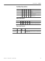
PanelView 900 Monochrome Terminals
These terminals are no longer available for purchase.
Operator
Input
Touch Screen
Communication Port
RIO
DH-485
RS-232
(DH-485)
DH+
DeviceNet
ControlNet
RS-232
(DF1)
x
Printer Port Catalog Number(1)
RS-232
x
x
2711-T9A2
x
x
x
x
x
x
x
x
x
2711-T9A8
x
2711-T9A9
x
2711-T9A10
x
2711-T9A15
x
2711-T9A16
x
2711-K9A1
x
2711-K9A2
x
x
x
2711-K9A3
2711-K9A5
x
x
x
x
x
(1)
2711-T9A3
2711-T9A5
x
Keypad
2711-T9A1
x
2711-K9A8
x
2711-K9A9
x
2711-K9A10
x
2711-K9A15
x
2711-K9A16
Add L1 to the end of the catalog number for 24V DC power.
Publication 2711-UM014G-EN-P - September 2008
21
Chapter 1
Terminal Overview
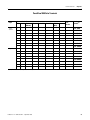
PanelView 900 Color Terminals
These terminals are no longer available for purchase.
Operator
Input
Touch
Screen
Communication Port
RIO
DH-485 RS-232
DH+
(DH-485)
DeviceNet
ControlNet RS-232 Ethernet
(DF1)
x
x
x
x
x
x
x
x
Keypad
x
x
x
x
x
x
x
x
(1)
22
Printer
Port
RS-232
Catalog
Number(1)
x
2711-T9C1
x
2711-T9C3
x
2711-T9C8
x
2711-T9C9
x
2711-T9C10
x
2711-T9C15
x
2711-T9C16
x
2711-T9C20
x
2711-K9C1
x
2711-K9C3
x
2711-K9C8
x
2711-K9C9
x
2711-K9C10
x
2711-K9C15
x
2711-K9C16
x
2711-K9C20
Add L1 to the end of the catalog number for 24V DC power.
Publication 2711-UM014G-EN-P - September 2008
Terminal Overview
Chapter 1
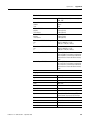
PanelView 1000 Color Terminals
Operator
Input
Touch
Screen
Communication Port
RIO DH-485 RS-232
DH+
(DH-485)
DeviceNet ControlNet
Printer
Port
RS-232 Ethernet RS-232
(DF1)
x
x
x
x
x
x
x
x
Keypad
x
x
x
x
x
x
x
x
(1)
Catalog
Number(1)
x
2711-T10C1
x
2711-T10C3
x
2711-T10C8
x
2711-T10C9
x
2711-T10C10
x
2711-T10C15
x
2711-T10C16
x
2711-T10C20
x
2711-K10C1
x
2711-K10C3
x
2711-K10C8
x
2711-K10C9
x
2711-K10C10
x
2711-K10C15
x
2711-K10C16
x
2711-K10C20
Add L1 to the end of the catalog number for 24V DC power.
Publication 2711-UM014G-EN-P - September 2008
23
Chapter 1
Terminal Overview
PanelView 1000 Grayscale Terminals
Operator
Input
Touch
Screen
Communication Port
RIO
DH-485 RS-232
(DH-485)
DH+
Printer
Port
DeviceNet ControlNet RS-232 Ethernet RS-232
(DF1)
x
x
x
x
x
x
x
x
Keypad
x
x
x
x
x
x
x
x
(1)
24
Catalog
Number(1)
x
2711-T10G1
x
2711-T10G3
x
2711-T10G8
x
2711-T10G9
x
2711-T10G10
x
2711-T10G15
x
2711-T10G16
x
2711-T10G20
x
2711-K10G1
x
2711-K10G3
x
2711-K10G8
x
2711-K10G9
x
2711-K10G10
x
2711-K10G15
x
2711-K10G16
x
2711-K10G20
Add L1 to the end of the catalog number for 24V DC power.
Publication 2711-UM014G-EN-P - September 2008
Terminal Overview
Chapter 1
PanelView 1400 Color Terminals
These terminals are no longer available for purchase.
Operator
Input
Touch
Screen
Communication Port
RIO
DH-485
RS-232
DH+
(DH-485)
DeviceNet ControlNet
RS-232 Ethernet
(DF1)
x
x
x
x
x
x
x
Keypad
x
x
x
x
x
x
x
x
x
Publication 2711-UM014G-EN-P - September 2008
Printer
Port
RS-232
Catalog
Number
x
2711-T14C1
x
2711-T14C3
x
2711-T14C8
x
2711-T14C9
x
2711-T14C10
x
2711-T14C15
x
2711-T14C16
x
2711-T14C20
x
2711-K14C1
x
2711-K14C3
x
2711-K14C8
x
2711-K14C9
x
2711-K14C10
x
2711-K14C15
x
2711-K14C16
x
2711-K14C20
25
Chapter 1
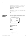
Terminal Overview
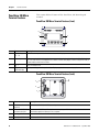
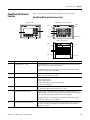
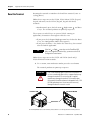
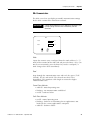
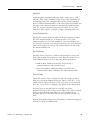
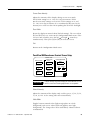
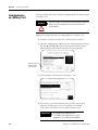
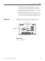
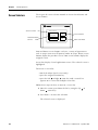
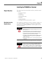
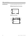
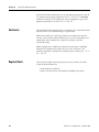
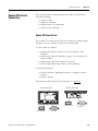
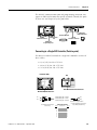
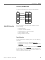
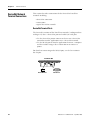
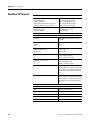
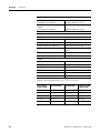
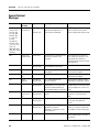
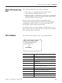
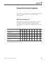
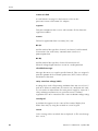
PanelView 300 Micro
Terminal Features
This section defines features of the PanelView 300 Micro keypad
terminal.
PanelView 300 Micro Terminal Features (front)
4
2
2
1
3
#
Feature
Description
1
Function keys
(F1…F4)
Use the function keys to initiate functions on the terminal display.
2
Cursor keys
Use the cursor keys (left, right, up, down) as programmed function keys in addition to the F1…F4 function
keys or to move the cursor in displayed lists, to select a numeric entry object, to enter configuration mode, or
to enter/modify numeric and ascii data.
3
4
Stores an entered value.
Keypad
terminal display
Liquid crystal display with integral backlight. Displays application text, controls, graphics.
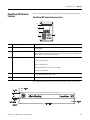
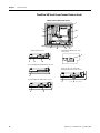
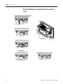
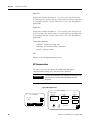
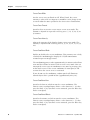
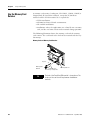
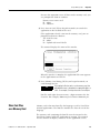
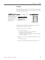
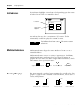
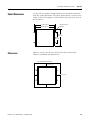
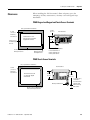
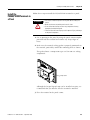
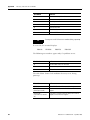
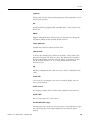
PanelView 300 Micro Terminal Features (back)
4
3
2
1
#
Feature
Description
1
Power connection
terminals
Connects to a 24V DC (11-30V DC) external power source.
2
DF1 or DH-485 (RS232)
communication port
Connects to an SLC, PLC, or MicroLogix controller by using an RS-232 connection. Also used for
downloading applications directly from a computer.
3
Sealing gasket
Seals the front of the terminal to an enclosure or panel.
4
Nameplate label
Provides product information.
26
Publication 2711-UM014G-EN-P - September 2008
Terminal Overview
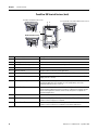
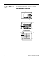
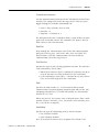
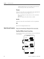
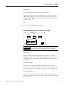
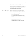
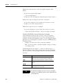
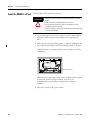
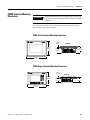
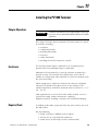
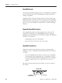
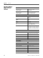
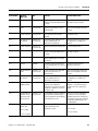
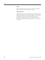
PanelView 300 Terminal
Features
Chapter 1
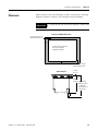
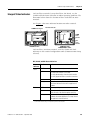
This section defines features of the PanelView 300 keypad terminal.
PanelView 300 Terminal Features (front)
5
4
1
2
3
#
Feature
Description
1
Function keys (F1…F8)
Use the function keys to initiate functions on the terminal display. These keys may have
custom legends.
2
Cursor keys
Use the up or down cursor keys to move the cursor up or down in a list or to
increment/decrement values. Use the left or right cursor keys to select an object with an
indicator bar, or to enter configuration mode.
3
Numeric entry keys
0…9 - Enters numeric values.
. Enters a decimal point.
- Enters a negative value.
←Clears entered digits or cancels the scratchpad.
↵ Stores an entered value.
4
Keypad terminal display
Initiate the function of a displayed object, such as an ON or OFF push button, by pressing
the corresponding function key (F1...F8).
5
OEM label option (series B and later)
Contact Rockwell Automation or your authorized distributor for custom label information.
The following illustration shows the dimensions for the OEM label.
Publication 2711-UM014G-EN-P - September 2008
27
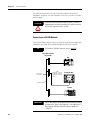
Chapter 1
Terminal Overview
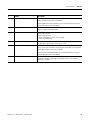
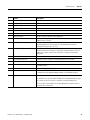
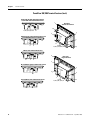
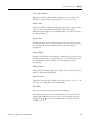
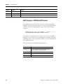
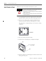
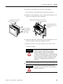
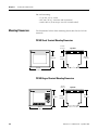
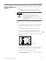
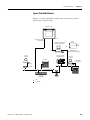
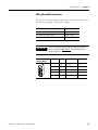
PanelView 300 Terminal Features (back)
DeviceNet with additional RS-232 Port
3
4
RS-232 (DH-485 or DF1) without additional RS-232 Port
5
10
12
9 or 11
2
DH-485 without RS-232 Port
6
1
8
7
7, 8, 9, 10, 11, 12
#
Feature
Description
1
Nameplate label
Provides product information.
2
Sealing gasket
Seals the front of the terminal to an enclosure or panel.
3
COMM Status indicator (green)
Indicates when communication is occurring.
4
FAULT Status indicator (red)
Indicates firmware or hardware faults.
5
Memory card slot
Accepts a memory card which stores applications.
6
Power connection terminals
Connects to an external 24V DC power source (18…32V DC).
7
DH-485 communication port
Connects to an SLC or MicroLogix controller, DH-485 network, or Wallmount Power
Supply (Cat. No. 1747-NP1).
8
DH-485 programming connector
Connects to a Personal Computer Interface Converter (Cat. No. 1747-PIC) for
transferring applications. Also connects to an SLC programmer, such as the
Hand-held Terminal (Cat. No. 1747-PT1).
9
RS-232 (DH-485) communication port
Connects to the Channel 0 port of an SLC 5/03, SLC 5/04, or SLC 5/05 controller for
point-to-point DH-485 communication. Connects to a MicroLogix controller through
an AIC+ Link Coupler. Also connects to the RS-232 serial port of a computer for
transferring applications.
10
DeviceNet connector
Connects to a DeviceNet network.
11
RS-232 (DF1) communication port
Connects to a PLC, SLC, or MicroLogix controller with a DF1 port. This port also
connects to the RS-232 port of a computer.
12
RS-232 Printer/File transfer port
Connects to a printer (K3A10L1 version only). On a DeviceNet terminal, this port also
connects to the RS-232 port of a computer for transferring applications.
28
Publication 2711-UM014G-EN-P - September 2008
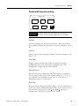
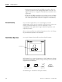
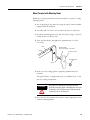
Terminal Overview
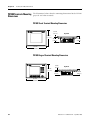
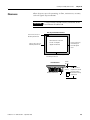
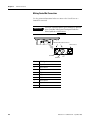
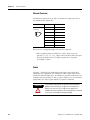
PanelView 550 Terminal
Features
Chapter 1
This section defines features of the PanelView 550 terminals.
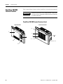
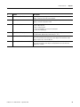
PanelView 550 Terminal Features (front)
Keypad Terminal
Keypad & Touch Screen Terminal
Cell 16
Cell 1
5
4
3
6
Cell 113
1
Cell 128
2
Touch Screen Terminal
Cell 1
Cell 16
5
6
Cell 113
Cell 128
#
Feature
Description
1
Function Keys (F1…F10)
On keypad terminals, use the function keys to initiate functions on the terminal
display. These keys may have custom legends.
On keypad and touch screen terminals, you can initiate functions by using the
function keys and/or touch screen objects.
2
Cursor Keys
Use the cursor keys to move the cursor in displayed lists, to select a numeric entry
object, or to enter configuration mode.
3
Numeric Entry Keys
0…9 - Enters numeric values.
. Enters a decimal point.
- Enters a negative value.
←Clears entered digits or cancels the scratchpad.
↵ Stores an entered value.
4
Keypad Terminal Display
On keypad terminals, initiate the function of a displayed object, such as an ON or
OFF push button, by pressing a function key (F1…F10).
5
Touch Screen Terminal Display
On touch screen or keypad & touch screen terminals, initiate the function of a
displayed object, such as an ON or OFF push button, by touching the screen object.
Each interactive screen object occupies one or more of 128 cells.
On keypad and touch screen terminals, you can initiate functions by using the
function keys and/or touch screen objects.
6
Touch Cells (Touch Screen terminal)
Publication 2711-UM014G-EN-P - September 2008
The 128 touch cells (16 columns x 8 rows) let you initiate functions by touching
the screen. Interactive screen objects are aligned with touch cells when the
application is created.
29
Chapter 1
Terminal Overview
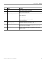
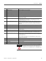
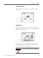
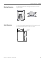
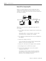
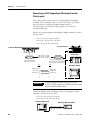
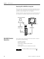
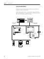
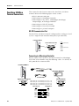
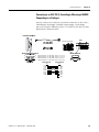
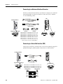
PanelView 550 Keypad or Keypad and Touch Screen Terminals
(back)
DH-485 without additional RS-232 Port
4
5
3
2
6
1
7
AC connector shown, DC
connector looks different
11
10
8
DH-485 with additional RS-232 Port
19
11
10
RS-232 (DH-485)
without additional RS-232 Port
12
9
Backlight lamp behind access cover
Series G and earlier
Remote I/O, DF1, DH+, DeviceNet, ControlNet, Ethernet,
with additional RS-232 Port
13, 14, 15, 16, 17, or 18
19
RS-232 (DH-485)
with additional RS-232 Port
19
30
12
Publication 2711-UM014G-EN-P - September 2008
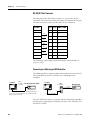
Terminal Overview
Chapter 1
#
Feature
Description
1
Power Connection Terminals
Connects to external power source.
2
Nameplate Label
Provides product information.
3
Sealing Gasket
Seals the front of the terminal to an enclosure or panel.
4
COMM Status (Green) Indicator
Indicates when communication is occurring.
5
FAULT Status (Red) Indicator
Indicates firmware or hardware faults.
6
Memory Card Slot
Accepts a memory card which stores applications.
7
Access Cover
Provides access to the replaceable backlight lamp.
8
Backlight Lamp
Light source for the display backlight. Light transmits through a fiber-optic bundle to
the back of the LCD display.(1)
9
Spare Bulb Holder
Stores a spare backlight lamp.(1)
10
DH-485 Communication Port
Connects to an SLC or MicroLogix controller, DH-485 network, or Wallmount Power
Supply (Cat. No. 1747-NP1).
11
DH-485 Programming Connector
Connects to a Personal Computer Interface Converter (Cat. No. 1747-PIC) for
transferring applications. Also connects to an SLC programmer, such as the
Hand-held Terminal (Cat. No. 1747-PT1).
12
RS-232 (DH-485) Communication Port
Connects to the Channel 0 port of an SLC 5/03, SLC 5/04, or SLC 5/05 controller for
point-to-point DH-485 communication. Connects to a MicroLogix controller through
an AIC+ Link Coupler. Also connects to the RS-232 serial port of a computer for
transferring applications.
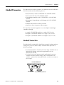
13
Remote I/O Port
Connects to a scanner or sub-scanner on a remote I/O network.
14
DH+ Communication Port
Connects to a PLC-5, SLC 5/04, or ControlLogix controller on a DH+ link.
15
DeviceNet Connector
Connects to a DeviceNet network.
16
ControlNet Connector
Connects to a ControlLogix controller (with 1756-CNB module) or PLC-5 on a
ControlNet network.
17
RS-232 (DF1) Communication Port
Connects to a PLC, SLC, or MicroLogix controller with a DF1 port.
18
Ethernet Connector
Connects to a PLC-5E or SLC 5/05 controller, or a ControlLogix, MicroLogix, FlexLogix,
or CompactLogix controller (with appropriate bridge module) on an EtherNet/IP
network.
19
RS-232 Printer/ File Transfer Port
Connects to a printer.
On remote I/O, DH+, DF1, DeviceNet, EtherNet/IP, or ControlNet terminals, this port
also connects to the RS-232 port of a computer for transferring applications.
The RS-232 port on the DH-485 or RS-232 (DH-485) terminal is used to connect a
printer but not for file transfers.
(1)
Series H and later PanelView 550 Keypad and Keypad Touch Terminals have an integrated LED backlight. This backlight is non-replaceable.
Publication 2711-UM014G-EN-P - September 2008
31
Chapter 1
Terminal Overview
PanelView 550 Touch Screen Terminal Features (back)
DH-485 without additional RS-232 Port
5
4
6
3
2
7
1
11
DH-485 with RS-232 Port
10
9
8
Backlight lamp behind access cover
Series A only
9
11
10
19
RS-232 (DH-485) without additional RS-232 Port
Remote I/O, DF1, DH+, DeviceNet,
ControlNet, Ethernet, with RS-232 Port
12
RS-232 (DH-485) with additional RS-232 Port
19
12
32
13, 14, 15, 16, 17, or 18
19
Publication 2711-UM014G-EN-P - September 2008
Terminal Overview
Chapter 1
#
Feature
Description
1
Power Connection Terminals
Connects to external DC power source.
2
Sealing Gasket
Seals the front of the terminal to an enclosure or panel.
3
FAULT Status (Red) Indicator
Indicates firmware or hardware faults.
4
COMM Status (Green) Indicator
Indicates when communication is occurring.
5
Nameplate Label
Provides product information.
6
Memory Card Slot
Accepts a memory card which stores applications.
7
Reset Button
Resets the terminal.
8
Access Cover
Provides access to the replaceable backlight lamp.(1)
9
Backlight Lamp
Light source for the display backlight. (1)
10
DH-485 Communication Port
Connects to an SLC or MicroLogix controller, DH-485 network, or Wallmount Power
Supply (Cat. No. 1747-NP1).
11
DH-485 Programming Connector
Connects to a Personal Computer Interface Converter (Cat. No. 1747-PIC) for
transferring applications. Also connects to an SLC programmer, such as the
Hand-held Terminal (Cat. No. 1747-PT1).
12
RS-232 (DH-485) Communication Port
Connects to the Channel 0 port of an SLC 5/03, 5/04, or 5/05 for point-to-point
DH-485 communication. Connects to a MicroLogix controller through an AIC+ Link
Coupler. Also connects to the RS-232 serial port of a computer for transferring
applications.
13
Remote I/O Port
Connects to a scanner or sub-scanner on a remote I/O network.
14
DH+ Communication Port
Connects to a PLC-5, SLC 5/04, or ControlLogix controller on a DH+ link.
15
DeviceNet Connector
Connects to a DeviceNet network.
16
ControlNet Connector
Connects to a ControlLogix controller (with 1756-CNB module) or PLC-5 on a
ControlNet network.
17
RS-232 (DF1) Communication Port
Connects to a PLC, SLC, or MicroLogix controller with a DF1 port.
18
Ethernet Connector
Connects to a PLC-5E or SLC 5/05 controller, or a ControlLogix, MicroLogix, FlexLogix
or CompactLogix (with appropriate bridge module) on an EtherNet/IP network.
19
RS-232 Printer/File Transfer Port
Connects to a printer.
On remote I/O, DH+, DF1, DeviceNet, EtherNet/IP, or ControlNet terminals, this port
also connects to the RS-232 port of a computer for transferring applications.
The RS-232 port on the DH-485 or RS-232 (DH-485) terminal is used to connect a
printer but not for file transfers.
(1)
Series B and later PanelView 550 Touch Terminals have an integrated LED backlight. This backlight is non-replaceable.
Publication 2711-UM014G-EN-P - September 2008
33
Chapter 1
Terminal Overview
PanelView 600 Terminal
Features
This section defines features of the PanelView 600 terminals.
PanelView 600 Terminal Features (front)
Keypad Terminal
3
4
1
2
Keypad & Touch Screen Terminal
Cell 16
Cell 1
5
6
Cell 128
Cell 113
Touch Screen Terminal
Cell 1
Cell 16
5
6
Cell 128
Cell 113
34
Publication 2711-UM014G-EN-P - September 2008
Terminal Overview
Chapter 1
#
Feature
Description
1
Function Keys (F1…F10)
Use the function keys on keypad terminals to initiate functions on the terminal
display. These keys may have custom legends.
On the keypad & touch screen terminals, you can initiate functions by using the
function keys and/or touch screen objects.
2
Cursor Keys
Use the cursor keys to move the cursor in displayed lists, to select a numeric entry
object, or to enter configuration mode.
3
Numeric Entry Keys
0…9 - Enters numeric values.
. Enters a decimal point.
- Enters a negative value.
←Clears entered digits or cancels the scratchpad.
↵ Stores an entered value.
4
Keypad Terminal Display
On keypad terminals, initiate the function of a displayed object, such as an ON or
OFF push button, by pressing a function key (F1...F10).
5
Touch Screen Terminal Display
On keypad and touch screen terminals, initiate the function of a displayed object,
such as an ON or OFF push button, by touching the screen object. Each interactive
screen object occupies one or more of 128 cells.
On touch screen and keypad terminals, you can initiate functions, by using the
function keys and/or touch screen objects.
6
Touch Cells (Touch Screen terminal)
Publication 2711-UM014G-EN-P - September 2008
The 128 touch cells (16 columns x 8 rows) let you initiate functions by touching
the screen. Interactive screen objects are aligned with touch cells when the
application is created.
35
Chapter 1
Terminal Overview
PanelView 600 Keypad or Keypad & Touch Screen Terminal
(back)
Remote I/O, DF1, DH+, DeviceNet, ControlNet,
or Ethernet with additional RS-232 Port
4
10, 11, 12, 13, 14, or 15
16
DH-485 without additional RS-232 Port
3
2
7
8
1
7, 8, 9, 10
11, 12, 13, 14, 15, 16
6
DH-485 with additional RS-232 Port
16
7
8
RS-232 (DH-485)
without additional RS-232 Port
9
36
5
RS-232 (DH-485) with additional RS-232 Port
16
9
Publication 2711-UM014G-EN-P - September 2008
Terminal Overview
Chapter 1
#
Feature
Description
1
Power Connection Terminals
Connects to external power source.
2
Nameplate Label
Provides product information.
3
Memory Card Slot
Accepts a memory card which stores applications.
4
Sealing Gasket
Seals the front of the terminal to an enclosure or panel.
5
FAULT Status (Red) Indicator
Indicates firmware or hardware faults.
6
COMM Status (Green) Indicator
Indicates when communication is occurring.
7
DH-485 Communication Port
Connects to an SLC or MicroLogix controller, DH-485 network, or Wallmount Power
Supply (Cat. No. 1747-NP1).
8
DH-485 Programming Connector
Connects to a Personal Computer Interface Converter (Cat. No. 1747-PIC) for
transferring applications. Also connects to an SLC programmer, such as the
Hand-held Terminal (Cat. No. 1747-PT1).
9
RS-232 (DH-485) Communication Port
Connects to the Channel 0 port of an SLC 5/03, 5/04, or 5/05 for point-to-point
DH-485 communication. Connects to a MicroLogix controller through an AIC+ Link
Coupler. Also connects to the RS-232 serial port of a computer for transferring
applications.
10
Remote I/O Port
Connects to a scanner or sub-scanner on a remote I/O network.
11
DH+ Communication Port
Connects to a PLC-5, SLC 5/04, or ControlLogix controller on a DH+ link.
12
DeviceNet Connector
Connects to a DeviceNet network.
13
ControlNet Connector
Connects to a ControlLogix controller (with 1756-CNB module) or PLC-5 on a
ControlNet network.
14
(RS-232) DF1 Communication Port
Connects to a PLC, SLC, or MicroLogix controller with a DF1 port.
15
Ethernet Connector
Connects to a PLC-5E or SLC 5/05 controller, or a ControlLogix, MicroLogix, FlexLogix,
or CompactLogix (with appropriate bridge module) on an EtherNet/IP network.
16
RS-232 Printer/File Transfer Port
Connects to a printer.
On remote I/O, DH+, DF1, DeviceNet, EtherNet/IP, or ControlNet terminals, this port
also connects to the RS-232 port of a computer for transferring applications.
The RS-232 port on the DH-485 or RS-232 (DH-485) terminal is used to connect a
printer but not for file transfers.
Publication 2711-UM014G-EN-P - September 2008
37
Chapter 1
Terminal Overview
PanelView 600 Touch Screen Terminal Features (back)
Remote I/O, DF1, DH+, DeviceNet, ControlNet,
or Ethernet with additional RS-232 Port
5
11, 12, 13, 14, 15, or 16
17
4
3
DH-485 without additional RS-232 Port
2
1
8
9
8, 9, 10, 11
12, 13, 14, 15, 16, 17
7
6
DH-485 with additional RS-232 Port
17
8
9
RS-232 (DH-485)
without additional RS-232 Port
10
38
RS-232 (DH-485) with additional RS-232 Port
17
10
Publication 2711-UM014G-EN-P - September 2008
Terminal Overview
Chapter 1
#
Feature
Description
1
Power Connection Terminals
Connects to external power source.
2
Nameplate Label
Provides product information.
3
Fault Status (Red)
Indicates firmware or hardware faults.
4
COMM Status (Green)
Indicates when communication is occurring.
5
Sealing Gasket
Seals the front of the terminal to an enclosure or panel.
6
Reset Button
Resets the terminal.
7
Memory Card Slot
Accepts a memory card which stores applications.
8
DH-485 Communication Port
Connects to an SLC or MicroLogix controller, DH-485 network, or Wallmount Power
Supply (Cat. No. 1747-NP1).
9
DH-485 Programming Connector
Connects to a Personal Computer Interface Converter (Cat. No. 1747-PIC) for
transferring applications. Also connects to an SLC programmer, such as the
Hand-held Terminal (Cat. No. 1747-PT1).
10
RS-232 (DH-485) Communication Port
Connects to the Channel 0 port of an SLC 5/03, 5/04, or 5/05 for point-to-point
DH-485 communication. Connects to a MicroLogix controller through an AIC+ Link
Coupler. Also connects to the RS-232 serial port of a computer for transferring
applications.
11
Remote I/O Port
Connects to a scanner or sub-scanner on a remote I/O network.
12
DH+ Communication Port
Connects to a PLC-5, SLC 5/04, or ControlLogix controller on a DH+ link.
13
DeviceNet Connector
Connects to a DeviceNet network.
14
ControlNet Connector
Connects to a ControlLogix controller (with 1756-CNB module) or PLC-5 on a
ControlNet network.
15
RS-232 (DF1) Communication Port
Connects to a PLC, SLC, or MicroLogix controller with a DF1 port.
16
Ethernet Connector
Connects to a PLC-5E or SLC 5/05 controller, or a ControlLogix, MicroLogix, FlexLogix,
or CompactLogix (with appropriate bridge module) on an EtherNet/IP network.
17
RS-232 Printer/File Transfer Port
Connects to a printer.
On remote I/O, DH+, DF1, DeviceNet, EtherNet/IP, or ControlNet terminals, this port
also connects to the RS-232 port of a computer for transferring applications.
The RS-232 port on the DH-485 or RS-232 (DH-485) terminal is used to connect a
printer but not for file transfers.
Publication 2711-UM014G-EN-P - September 2008
39
Chapter 1
Terminal Overview
PanelView 900/1000
Terminal Features
This section defines features of the PanelView 900 and 1000 terminals.
IMPORTANT
PanelView 900 terminals are no longer available. Contact your
local sales office or authorized Rockwell Automation Distributor
for suitable substitutes.
PanelView 900/1000 Terminal Features (front)
Keypad Terminal
Touch Screen Terminal
Cell 1
4
5
6
Cell 24
3
Cell 361
1
Cell 384
2
40
Publication 2711-UM014G-EN-P - September 2008
Terminal Overview
Chapter 1
#
Feature
Description
1
Function Keys (F1…F16)
Use the function keys on keypad terminals to initiate functions on the terminal
display. These keys may have custom legends.
2
Cursor Keys
Use the cursor keys to move the cursor in displayed lists, to select a numeric entry
object or to enter configuration mode.
3
Numeric Entry Keys
0…9 - Enters numeric values.
. Enters a decimal point.
- Enters a negative value.
←Clears entered digits or cancels the scratchpad.
↵ Stores an entered value.
4
Keypad Terminal Display
On keypad terminals, initiate the function of a displayed object, such as an ON or
OFF push button, by pressing a function key (F1…F16).
5
Touch Screen Terminal Display
On touch screen terminals, initiate the function of a displayed object, such as an
ON or OFF push button, by touching the screen object. Each interactive screen
object occupies one or more of 384 cells.
6
Touch Cells (Touch Screen terminal)
The 384 touch cells (24 columns x 16 rows) let you initiate functions by touching
the screen. Interactive screen objects are aligned with touch cells when the
application is created.
Publication 2711-UM014G-EN-P - September 2008
41
Chapter 1
Terminal Overview
PanelView 900/1000 Terminal Features (back)
Remote I/O, DF1, DH+, DeviceNet, Ethernet,
or ControlNet with additional RS-232 Port
4
Back View
Touch Screen Terminal
3
11, 12, 13, 14, 15, or 16
17
5
2
DH-485 Version without additional RS-232 Port
6
1
8
9
8, 9, 10
11, 12, 13, 14, 15, 16, 17
7
DH-485 with additional RS-232 Port
4
17
Back View
Keypad Terminal
9
8
3
RS-232 (DH-485) without additional RS-232 Port
5
2
6
10
1
RS-232 (DH-485) with additional RS-232 Port
17
42
8, 9, 10
11, 12, 13, 14, 15, 16, 17
7
10
Publication 2711-UM014G-EN-P - September 2008
Terminal Overview
Chapter 1
#
Feature
Description
1
Power Connection Terminals
Connects to external power source.
2
Nameplate Label
Provides product information.
3
Reset Button
Resets the terminal.
4
Sealing Gasket
Seals the front of the terminal to an enclosure or panel.
5
Memory Card Slot
Accepts a memory card which stores applications.
6
FAULT Status (Red) Indicator
Indicates firmware or hardware faults.
7
COMM Status (Green) Indicator
Indicates when communication is occurring.
8
DH-485 Communication Port
Connects to an SLC or MicroLogix controller, DH-485 network, or Wallmount Power
Supply (Cat. No. 1747-NP1).
9
DH-485 Programming Connector
Connects to a Personal Computer Interface Converter (Cat. No. 1747-PIC) for
transferring applications. Also connects to an SLC programmer, such as the
Hand-held Terminal (Cat. No. 1747-PT1).
10
RS-232 (DH-485) Communication Port
Connects to the Channel 0 port of an SLC 5/03, 5/04, or 5/05 for point-to-point
DH-485 communication. Connects to a MicroLogix controller through an AIC+ Link
Coupler. Also connects to the RS-232 serial port of a computer for transferring
applications.
11
Remote I/O Port
Connects to a scanner or sub-scanner on a remote I/O network.
12
DH+ Communication Port
Connects to a PLC-5, SLC 5/04, or ControlLogix controller on a DH+ link.
13
DeviceNet Connector
Connects to a DeviceNet network.
14
ControlNet Connector
Connects to a ControlLogix controller (with 1756-CNB module) or PLC-5 on a
ControlNet network.
15
RS-232 (DF1) Communication Port
Connects to a PLC, SLC, or MicroLogix controller with a DF1 port.
16
Ethernet Connector
Connects to a PLC-5E or SLC 5/05 controller, or a ControlLogix, MicroLogix, FlexLogix,
or CompactLogix (with appropriate bridge module) on an EtherNet/IP network.
17
RS-232 Printer/File Transfer Port
Connects to a printer.
On remote I/O, DH+, DF1, DeviceNet, EtherNet/IP, or ControlNet terminals, this port
also connects to the RS-232 port of a computer for transferring applications.
The RS-232 port on the DH-485 or RS-232 (DH-485) terminal is used to connect a
printer but not for file transfers.
Publication 2711-UM014G-EN-P - September 2008
43
Chapter 1
Terminal Overview
PanelView 1400 Terminal
Features
This section defines features of the PanelView 1400 terminals.
IMPORTANT
PanelView 1400 terminals are no longer available. Contact your
local sales office or authorized Rockwell Automation Distributor
for suitable substitutes.
PanelView 1400 Terminal Features (front)
Keypad Terminal
Touch Screen Terminal
Cell 1
3
4
5
6
Cell 361
1
44
Cell 24
Cell 384
2
Publication 2711-UM014G-EN-P - September 2008
Terminal Overview
Chapter 1
#
Feature
Description
1
Function Keys (F1…F21)
Use the function keys on keypad terminals to initiate functions on the terminal
display. These keys may have custom legends.
2
Cursor Keys
Use the cursor keys to move the cursor in displayed lists, to select a numeric entry
object, or to enter configuration mode.
3
Numeric Entry Keys
0…9 - Enters numeric values.
. Enters a decimal point.
- Enters a negative value.
← Clears entered digits or cancels the scratchpad.
↵ Stores an entered value.
4
Keypad Terminal Display
On keypad terminals, initiate the function of a displayed object, such as an ON or
OFF push button, by pressing a function key (F1…F21).
5
Touch Screen Terminal Display
On touch screen terminals, initiate the function of a displayed object, such as an
ON or OFF push button, by touching the screen object. Each interactive screen
object occupies one or more of 384 cells.
6
Touch Cells (Touch Screen terminal)
The 384 touch cells (24 columns x 16 rows) let you initiate functions by touching
the screen. Interactive screen objects are aligned with touch cells when the
application is created.
Publication 2711-UM014G-EN-P - September 2008
45
Chapter 1
Terminal Overview
PanelView 1400 Terminal Features (back and sides)
Remote I/O, DF1, DH+, DeviceNet, ControlNet,
or Ethernet with additional RS-232 Port
19
1
18
17
16
7, 8, 9
10, 11, 12
13, 14, 15, 16
2
10, 11, 12, 13, 14, or 15
DH-485 with additional RS-232 Port
6
5
4
3
Left Side
7
8
16
20
RS-232 (DH-485) with additional RS-232 Port
Right Side
9
16
21
46
Publication 2711-UM014G-EN-P - September 2008
Terminal Overview
#
1
2
3
4
5
6
7
Feature
Brightness Control
Contrast Control
Nameplate Label
FAULT Status (Red)
COMM Status (Green)
Power Connection Terminals
DH-485 Communication Port
8
DH-485 Programming Connector
9
RS-232 (DH-485) Communication Port
10
11
12
13
Remote I/O Port
DH+ Communication Port
DeviceNet Connector
ControlNet Connector
14
15
RS-232 (DF1) Communication Port
Ethernet Connector
16
RS-232 Printer/File Transfer Port
17
18
19
20
21
Memory Card Eject Button
Memory Card Slot
Sealing Gasket
Reset Button
CRT Board Adjustments
Description
Adjusts the brightness of the color display.
Adjusts the contrast of the color display.
Provides product information.
Indicates firmware or hardware faults.
Indicates when communication is occurring.
Connects to external power source.
Connects to an SLC or MicroLogix controller, DH-485 network, or Wallmount Power
Supply (Cat. No. 1747-NP1).
Connects to a Personal Computer Interface Converter (Cat. No. 1747-PIC) for
transferring applications. Also connects to an SLC programmer, such as the
Hand-held Terminal (Cat. No. 1747-PT1).
Connects to the Channel 0 port of an SLC 5/03, 5/04, or 5/05 for point-to-point
DH-485 communication. Connects to a MicroLogix controller through an AIC+ Link
Coupler. Also connects to the RS-232 serial port of a computer for transferring
applications.
Connects to a scanner or sub-scanner on a remote I/O network.
Connects to a PLC-5, SLC 5/04, or ControlLogix controller on a DH+ link.
Connects to a DeviceNet network.
Connects to a ControlLogix controller (with 1756-CNB module) or PLC-5 on a
ControlNet network.
Connects to a PLC, SLC or MicroLogix controller with a DF1 port.
Connects to a PLC-5E or SLC 5/05 controller, or a ControlLogix, MicroLogix, FlexLogix,
or CompactLogix (with appropriate bridge module) on an EtherNet/IP network.
Connects to a printer. On remote I/O, DH+, DF1, DeviceNet, EtherNet/IP, or
ControlNet terminals, this port also connects to the RS-232 port of a computer for
transferring applications.
The RS-232 port on the DH-485 or RS-232 (DH-485) terminal is used to connect a
printer but not for file transfers.
Ejects memory card from slot.
Accepts a memory card which stores applications.
Seals the front of the terminal to an enclosure or panel.
Resets the terminal.
See the warning below.
ATTENTION
Publication 2711-UM014G-EN-P - September 2008
Chapter 1
Only qualified service technicians should access the CRT board
adjustments. Failure to follow this caution could result in
electrical shock, a misadjusted monitor, or a damaged monitor.
47
Chapter 1
Terminal Overview
Applications
PanelView terminals operate with custom designed applications. The
first time you power on the terminal, (no application file loaded), the
terminal displays the Configuration Mode menu.
Chapter 3 describes the terminal functions you can configure from this
menu.
TIP
Remote I/O terminals provide an out-of-box application for
setting remote I/O communication parameters.
If an application is loaded, the terminal displays the application’s
start-up screen.
TIP
The application designer is responsible for documenting the
operation of the application and selecting a startup screen.
How the terminal operates depends on the application and the type of
terminal (touch screen or keypad).
48
Publication 2711-UM014G-EN-P - September 2008
Terminal Overview
Chapter 1
Touch Screen Operation
Applications for touch screen terminals are controlled by touching
screen objects.
Keypad Operation
Applications for keypad terminals are controlled by pressing function
keys that correspond to screen objects. Data is entered manually by
using the numeric entry keys.
A function key legend kit is available for each terminal (except the
PV300 Micro terminal) to create custom labels for the function keys.
See the accessories at the end of this chapter.
ATTENTION
Publication 2711-UM014G-EN-P - September 2008
Do not press multiple touch screen objects or multiple function
keys at the same time. This may result in unintended operation.
49
Chapter 1
Terminal Overview
IMPORTANT
Configuration Mode Menu
The keypad is designed for finger or gloved finger operation.
The touch screen may be operated with a finger, gloved finger,
or with a touch screen plastic stylus device with a minimum tip
radius of 1 mm (0.040 in) to prevent damage to the touch
screen. Using any other object or tool may damage the keypad
or touch screen.
You can configure terminal functions from the Configuration Mode
menu. These functions include how to:
•
•
•
•
•
•
•
•
select a language.
upload/download applications with a memory card.
set or display serial communication parameters.
select preset values.
obtain terminal and application information.
adjust screen parameters.
set time and date.
set printer parameters (for terminals with an RS-232 printer
port).
• return to run mode.
Chapter 3 describes how to enter configuration mode and operations
you can perform by using the Configuration Mode menu.
Terminal Messages
Terminal messages display:
• status of an operation.
• minor faults, errors, or numeric entry mistakes.
• operator prompts.
Appendix B describes terminal messages and provides a list of
recommended actions.
50
Publication 2711-UM014G-EN-P - September 2008
Terminal Overview
Printing
Chapter 1
PanelView terminals equipped with an RS-232 printer port can print:
•
•
•
•
triggered messages in a message display.
triggered states of a multistate indicator.
alarm messages.
alarm lists.
Print attributes for objects are defined in the application.
Any printer that supports the IBM enhanced character set can be
connected to the RS-232 printer port of a PanelView terminal.
Alarm List
PanelView terminals support an Alarm List queue to store information
on triggered alarms. The Alarm List stores a maximum of 100 alarms
or as many as the terminal can hold in nonvolatile RAM. The number
of alarms stored in the list is configured by using the PanelBuilder32
software.
The Alarm List stores the following data for each alarm:
•
•
•
•
•
Acknowledge indicator
Alarm date and time
Acknowledge date and time
Alarm trigger value
Alarm text including variables
The Alarm List is cleared:
• when an application is downloaded to the terminal.
• when the terminal is reset or power is cycled.
The Alarm List object may appear on the Alarm Banner or other
application screens. The data that displays in the Alarm List is
configured using the PanelBuilder32 software.
Publication 2711-UM014G-EN-P - September 2008
51
Chapter 1
Terminal Overview
Accessories
This section lists the accessories available for the PanelView terminals.
Software
Cat. No.
300M 300 550 600 900 1000 1400 Description
2711-ND3
x
x
x
x
x
x
x
Windows software required for creating
PanelView applications on a personal
computer.
Function Key Legend Kits
Cat. No.
300
2711-NF1
550
600
900
1000
1400
x
Description
5 legend inserts with key labels F1…F10 on one side. Use blank side
to create custom labels.
2711-NF2A
x
1 legend insert for PV900 keypad (monochrome) terminal with key
labels F1…F16 on one side. Use blank side to create custom labels.
2711-NF2C
x
1 legend insert for PV900 keypad (color) terminal with key labels
F1…F16 on one side. Use blank side to create custom labels.
2711-NF4
x
1 legend insert with key labels F1…F10 on one side. Use blank side to
create custom labels.
2711-NF5
x
2711-NF6
x
2711-NF7
2 legend inserts. One has key labels F1…F16; the other has key labels
F17…F21. Use blank sides to create custom labels.
1 legend insert with key labels F1…F16. Use blank side to create
custom labels.
x
2 legend inserts with key labels F1…F4 and F5…F8. Use blank side to
create custom labels.
Memory Cards and Retainer
Cat. No.
300
550
600
900
1000
1400
Description
x
x
x
x
x
x
256K memory card for storing applications.
2711-NM13
x
x
x
x
x
x
2M flash memory card for storing applications.
2711-NM14
x
x
x
x
x
x
4M flash memory card for storing applications.
2711-NM15
x
x
x
x
x
x
10M flash memory card for storing applications.
2711-NM216(1)
x
x
x
x
x
x
16M flash ATA card for storing applications and font files.
2711-NM232
x
x
x
x
x
x
32M flash ATA card for storing applications and font files.
2711-NMCC
x
x
x
x
2711-NMCD
x
2711-NM11
(1)
2711-NMCE
52
x
Secures memory card in the PanelView 500/600 keypad or the
PanelView 900/1000 keypad and touch screen. Prevents electrostatic
discharge.
Secures memory card in 550 touch screen terminal and prevents
electrostatic discharge.
x
Secures memory card in PanelView 300 keypad and 600 touch screen
terminals and prevents electrostatic discharge.
Publication 2711-UM014G-EN-P - September 2008
Terminal Overview
(1)
Chapter 1
Contact Rockwell Automation for availability.
Antiglare Overlay
Self-adhesive filters minimize the reflection of terminal displays.
Cat. No.
300M 300 550 600 900 1000
2711-NV4 (Keypad)
x
2711-NV4T (Touch Screen Terminals)
x
x
2711-NV3K (Keypad)
x
2711-NV3T (Touch Screen Terminals)
x
2711-NV5 (Keypad)
1400
x
2711-NV7K (Keypad Terminals)
x
2711-NV7T (Touch Screen Terminals)
x
2711-NV6K (Keypad Terminals)
x
2711-NV6T (Touch Screen Terminals)
x
2711-NV8 (Keypad Terminals)
x
DH-485 Operating and Programming Cables
Cat. No.
Description
1747-PIC
Personal Computer Interface Converter converts RS-232 signals to/from RS-485 signals. Use to transfer
applications between a DH-485 terminal and a computer.
1747-C10
1.83 m (6 ft) cable connects a DH-485 terminal to an SLC or DH-485 network.
1747-C11
0.30 m (1 ft) cable connects a DH-485 terminal to an SLC or DH-485 network.
1747-C20
6.1 m (20 ft) cable connects a DH-485 terminal to an SLC or DH-485 network.
1747-CP3
45 cm (17.7 in.) cable connects an RS-232 terminal to an AIC+ (Port1) through a null modem adapter.
1761-CBL-AP00
45 cm (17.7 in.) cable connects an RS-232 terminal to an AIC+ (Port2) through a null modem adapter.
1761-CBL-AC00
3 m (9.8 ft) cable connects an RS-232 terminal to an AIC+ (Port1) through a null modem adapter.
1761-CBL-AS03
3 m (9.8 ft) cable connects a DH-485 terminal to an AIC+ (Port3).
1761-CBL-AS09
9.9 m (29.5 ft) cable connects a DH-485 terminal to an AIC+ (Port3).
1761-CBL-AM00
45 cm (17.7 in.) cable with 2 mini DIN, right angle connectors.
1761-CBL-HM02
2 m (6.5 ft) cable with 2 mini DIN, right angle connectors.
2711-CBL-HM05
5 m runtime cable with 2 mini DIN, right angle connectors.
2711-CBL-HM10
10 m runtime cable with 2 mini DIN, right angle connectors.
1761-CBL-PM00
45 cm (17.7 in.) cable connects an RS-232 terminal to an AIC+ (Port2) through a null modem adapter.
Publication 2711-UM014G-EN-P - September 2008
53
Chapter 1
Terminal Overview
Cat. No.
Description
1761-CBL-PM02
2 m (6.5 ft) cable connects an RS-232 terminal to an AIC+ (Port2) through a null modem adapter.
2711-CBL-PM05
5 m programming cable with a D-shell and mini DIN connector.
2711-CBL-PM10
10 m programming cable with a D-shell and mini DIN connector.
PanelView File Transfer Utility
Cat. No.
Description
2711-ND7
Transfers .PVA files between a PanelView terminal and a computer
running Windows.
Power Supply and Link Couplers
The following items are available for all PanelView terminals.
54
Cat. No.
Description
1747-NP1
Wallmount power supply provides power for DH-485 communication
when an SLC controller or network is not connected.
1747-AIC
AIC Link Coupler links devices on a DH-485 network.
1761-NET-AIC
AIC+ Advanced Interface Converter links devices on a DH-485
network including MicroLogix.
1761-NET-DNI
DeviceNet Interface links DF1 PanelViews on a DeviceNet network.
1761-NET-ENI
Ethernet Interface links DF1 or Ethernet devices on an EtherNet/IP
network.
Publication 2711-UM014G-EN-P - September 2008
Terminal Overview
Chapter 1
RS-232 Cables
Cat. No.
Description
2711-NC13
5 m (15 ft) connects an RS-232 terminal to the Channel 0 port of an
SLC 5/03 controller or the RS-232 port of a computer or printer.
2711-NC14
10 m (32 ft) cable connects an RS-232 terminal to the Channel 0 port
of an SLC 5/03 controller or the RS-232 port of a computer or printer.
2711-NC21
5 m (15 ft) connects an RS-232 terminal to a MicroLogix controller
(except PV300 Micro).
2711-NC22
15 m (49 ft) cable connects an RS-232 terminal to a MicroLogix
controller (except PV300 Micro).
2706-NC13
3 m (10 ft) cable connects an RS-232 terminal to an SLC 5/03
controller or the RS-232 port of a computer or printer.
1761-CBL-AP00
0.5 m (1.5 ft) cable connects a PanelView 300 Micro RS-232 terminal
to an SLC or PLC.
1761-CBL-PM02
2 m (6.5 ft) cable connects a PanelView 300 Micro RS-232 terminal to
an SLC or PLC.
2711-CBL-PM05
5 m (15 ft) cable connects a PanelView 300 Micro RS-232 terminal to
a ControlLogix, AIC+, SLC controller, or computer RS-232 port.
2711-CBL-PM10
10 m (30 ft) cable connects a PanelView 300 Micro RS-232 terminal to
a ControlLogix, AIC+, SLC controller, or computer RS-232 port.
1761-CBL-AMOO
0.5 m (1.5 ft) cable connects a PanelView 300 Micro RS-232 terminal
to a MicroLogix.
1761-CBL-HM02
2 m (6.5 ft) cable connects a PanelView 300 Micro RS-232 terminal to
a MicroLogix.
2711-CBL-HM05
5 m (15 ft) cable connects a PanelView 300 Micro RS-232 terminal to
a MicroLogix 1000/1200/1500, DeviceNet DNI, or AIC+ module.
2711-CBL-HM10
10 m (30 ft) cable connects a PanelView 300 Micro RS-232 terminal to
a MicroLogix 1000/1200/1500, DeviceNet DNI, or AIC+ module.
Remote I/O or DH+ Cable
Publication 2711-UM014G-EN-P - September 2008
Cat. No.
Description
1770-CD
Shielded, 3-conductor cable (Belden 9463) for connecting a remote
I/O terminal to a remote I/O network.
55
Chapter 1
Terminal Overview
Replacement Parts
This section lists the replacement parts available for the PanelView
terminals.
Backlight Lamps
Cat. No.
550
2711-NL1
x
600
900
1000
Description
Halogen backlight lamp for all PV550
terminals. Provides backlighting for
LCD display.
2711-NL2
x
2711-NL3
Backlight for PV900 color terminal.
x
Backlight for PV600 color terminal.
2711-NL4
x
2711-NL5
Backlight for PV1000 color terminal.
x
Backlight for PV 600 (Series C only)
2711-NL6
x
Backlight for PV1000 color terminal
(Series B only)
2711-NL7
x
Backlight for PV1000 color terminal
(Series C only)
2711-NL9
x
Backlight for PV1000 color terminal
(Series D and Series E only)
Backlight for PV1000 grayscale
terminal (Series C and Series D only)
2711-NL10
x
Backlight for PV1000 color terminal
(Series F only)
Backlight for PV1000 grayscale
terminal (Series E only)
1400
Description
Real Time Clock Modules
Cat. No.
2711-NB2
x
2711-NB3
x
x
x
x
2711-NB4
56
300 550 600 900 1000
x
Real time clock module for PV550
(Series D or earlier). Does not apply
to the PV550 touch screen terminals.
Contains lithium battery.
x
x
x
x
Real time clock module for PV600,
PV900, PV1000, PV1400 or PV550
(Series E and F). Does not apply to
PV550/PV600 touch screen terminals.
Contains lithium battery.
Real time clock module for PV300,
PV550 (Series G and later),
PV550/PV600 touch screen, PV600
(Series C and later), PV1000 color
(Series D and later), and PV1000
grayscale (Series B and later)
terminals. Contains lithium battery.
Publication 2711-UM014G-EN-P - September 2008
Terminal Overview
Chapter 1
Panel Mount Clips and Studs
Cat. No.
600
900
1000
2711-NP1
2711-NP2
x
x
1400
Description
x
10 panel mount clips for PV1400
terminal.
x
6 panel mount clips for PV600, PV900
or PV1000 terminals.
2711-NP3
x
Optional panel mount studs (18) for
PV1400 terminals.
Remote I/O Connector
Cat. No.
550 600 900 1000 1400 Description
22112-046-03
x
x
x
x
x
Terminal block connector plugs into
remote I/O port of remote I/O terminals.
Power Input Connector
Cat. No.
300M
600 (touch
only)
Description
2711-TBDC
x
x
Removable dc power input connectors for PanelView 300
Micro (qty. of 10).
Publication 2711-UM014G-EN-P - September 2008
57
Chapter 1
58
Terminal Overview
Publication 2711-UM014G-EN-P - September 2008
Chapter
2
Applying Power and Resetting Terminal
Chapter Objectives
This chapter provides information on:
•
•
•
•
Wiring and Safety
Guidelines
wiring and safety guidelines.
connecting AC or DC power.
resetting the terminal.
power-up sequence.
Use publication NFPA 70E, Electrical Safety Requirements for
Employee Workplaces when wiring the PanelView terminals. In
addition to the NFPA general guidelines:
• connect the terminal to its own branch circuit.
• the input power should be protected by a fuse or circuit breaker
rated at no more than 15 Amps.
• route incoming power to the PanelView terminal by a separate
path from the communication cable.
IMPORTANT
Do not run signal wiring and power wiring in the same
conduit.
• where power and communication lines must cross, they should
cross at right angles. Communication lines can be installed in the
same conduit as low level DC I/O lines (less than 10V).
59Publication 2711-UM014G-EN-P - September 2008
59
Chapter 2
Applying Power and Resetting Terminal
Hazardous Location
Considerations
This equipment is suitable for use in Class I, Division 2, Groups A, B,
C, D; Class II, Division 2, Groups F and G; Class III; or non-hazardous
locations only. The following WARNING statement applies to use in
hazardous locations.
WARNING
EXPLOSION HAZARD
• Substitution of components may impair suitability for Class I, Class
II, Class III Division 2.
• Do not replace components or disconnect equipment unless power
has been switched off or the area is known to be non-hazardous.
• Do not connect or disconnect components unless power has been
switched off or the area is known to be non-hazardous.
• This product must be installed in an enclosure. All cables
connected to the product must remain in the enclosure or be
protected by conduit or other means.
• All wiring must comply with N.E.C. article 501-4(b), 502-4(b),
503-3(b) as appropriate.
See the nameplate on terminal for hazardous locations certifications.
ATTENTION
60
In Class I, Class II, Class III Division 2 Hazardous locations,
the PanelView terminal must be wired per the National
Electric Code as it applies to hazardous locations. Peripheral
equipment must also be suitable for the location in which it is
installed.
Publication 2711-UM014G-EN-P - September 2008
Applying Power and Resetting Terminal
Connect AC Power
Chapter 2
Below are AC electrical ratings for the PanelView terminals. The
PV550/PV600 touch screen only terminal is available only with DC
power, not AC power.
Terminal Type
Supply Voltage
Power Consumption,
Max
PV550
85…264V AC, 47…63 Hz
45 VA
PV600
85…264V AC, 43…63 Hz
60 VA
PV900M/PV900C
85…264V AC, 47…63 Hz
110 VA
PV1000G/PV1000C
85…264V AC, 47…63 Hz
55 VA
PV1400
85…264V AC, 43…63 Hz
200 VA
ATTENTION
Do not apply power to the PanelView terminal until all wiring
connections have been made. Failure to do so may result in
electrical shock.
The PanelView terminals are IEC 1131-2 Equipment Class I devices
and require you to connect the GND (Ground) or
(Protective
Earth) terminal to an earth conductor.
IMPORTANT
The PanelView terminals are designed for safe use when
installed in a NEMA Type 12, 13, 4X (indoor use only), IP54 or
IP65 rated enclosure.
Follow these steps to connect power to the AC versions of the
PanelView.
1. Secure AC power wires to the L1 and L2N terminal block screws.
2. Secure the Earth Ground/Protective Earth wire to the GND or
the
screw on the terminal block.
ATTENTION
Improper wiring of the power terminals may result in
voltage at the communication connector shells.
See the appropriate wiring diagram on page 62.
3. Apply power to the terminal.
Publication 2711-UM014G-EN-P - September 2008
61
Chapter 2
Applying Power and Resetting Terminal
PanelView 550 Terminal
120/240V AC, 3 Wire,
120/240V AC, 3 Wire,
European Harmonized Color Code
U.S. Color Code
L1 L2N GND
L1 L2N GND
Black (Line)
White (Neutral)
Blue (Neutral)
Green/Yellow
(Protective Earth)
Brown (Line)
Green (Earth Ground)
To Power Source
To Power Source
PanelView 900/1000 Terminal
Power Terminal
Block (fixed)
120/240V AC, 3 Wire,
European Harmonized Color Code
L1 L2N
GND/PE
120/240V AC, 3 Wire,
U.S. Color Code
GND/PE
L1 L2N
Black (Line)
White (Neutral)
Green (Earth Ground)
Brown (Line)
Blue (Neutral)
Green/Yellow (Protective Earth)
To Power Source
To Power Source
PanelView 1400 Terminal
Power Terminal (Fixed)
120/240V AC, 3 Wire,
U.S. Color Code
GND/PE
120/240V AC, 3 Wire,
European Harmonized Color Code
GND/PE
L2/N
L2/N
L1/L
62
L1/L
Green (Earth Ground)
White (Neutral)
Black (Line)
Green/Yellow (Protective Earth)
Blue (Neutral)
Brown (Line)
Publication 2711-UM014G-EN-P - September 2008
Applying Power and Resetting Terminal
Connect DC Power
Chapter 2
The L1 versions (Cat. No. 2711-K5 A5 A18...32V1L1, 2711-T9C1L1) of
the PV300, PV300 Micro, PV550, PV600, PV900, and PV1000 terminals
connect to a 24V DC power source.
The table below shows the electrical ratings for the DC versions of the
terminals. Electronic circuitry and an internal fuse protect the
terminals from reverse polarity and over-voltage conditions.
Terminal Type
Supply Voltage
(24V DC nominal)
Power Consumption, Max
PV300 Micro
11...30V DC
2.5 W (0.105 A @ 24V DC)
PV300
18...32V DC
6 W (0.25 A @ 24V DC)
PV550
18...30V DC
18 W (0.75 A @ 24V DC)
PV550 (touch only)
18...32V DC
18 W (0.75 A @ 24V DC)
PV600
18...32V DC
24 W (1.0 A @ 24V DC)
PV600 (touch only)
18...32V DC
24 W (1.0 A @ 24V DC)
PV900M
18...30V DC
58 W (2.5 A @ 24V DC)
PV900C
18...32V DC
50 W (2.1 A @ 24V DC)
PV1000G
18...32V DC
24 W (1.0 A @ 24V DC)
PV1000C
18...32V DC
24 W (1.0 A @ 24V DC)
ATTENTION
IMPORTANT
ATTENTION
ATTENTION
Publication 2711-UM014G-EN-P - September 2008
Do not connect a DC rated PanelView terminal to an AC power
source. Connecting to an AC power source may damage the
terminal.
The PanelView terminals are designed for use when installed in
a NEMA Type 12, 13, NEMA 4X (indoor use only), IP54 or IP65
rated enclosure.
Do not power PanelView terminals from the I/O power on a
controller or from DeviceNet network power. If you try to do
this, the PanelView will not power up and the DeviceNet or
controller power supply may be over-stressed.
Use only a safety extra-low voltage (SELV) power supply as a
source for the PanelView 300 Micro, PanelView 300 or 550
touch screen terminal. A SELV power supply does not exceed
42.4V DC.
63
Chapter 2
Applying Power and Resetting Terminal
Connect the power source to the terminal at the 3-screw terminal
block (PV300 Micro removable and PV600 Touch only, all others
fixed).
WARNING
Explosion Hazard
• Substitution of components may impair suitability for Class I,
Class II, Class III, Division 2.
• Do not replace components or disconnect equipment unless
power has been switched off or the area is known to be
non-hazardous.
• Do not connect or disconnect components unless power has been
switched off or the area is known to be non-hazardous.
• This product must be installed in an enclosure. All cables
connected to the product must remain in the enclosure or be
protected by conduit or other means.
• All wiring must comply with N.E.C. article 501-4(b).
64
Publication 2711-UM014G-EN-P - September 2008
Applying Power and Resetting Terminal
Chapter 2
Follow these steps to connect power to the dc versions of the
PanelView.
1. Secure the DC power wires to the terminal block screws.
PanelView 300 Terminal
PanelView 900/1000 Terminal
PanelView 550/600 Terminal
Power Terminal
Block (fixed)
Power Terminal
Block (fixed)
+
-
Note: In the PanelView 300, the Earth Ground
and DC Negative wires are internally connected.
Earth Ground
DC Negative
DC Positive
PanelView 300 Micro Terminal
Install Terminal Block
Press terminal block
base in first with
block leaning outward
Push top back to
vertical position
to lock-in.
DC Positive
-
DC Negative
+
Remove Terminal Block
Insert tip of screw driver
here.
Functional Earth Ground
Use #16 to #22 AWG Solid Wire or
#18 to #22 AWG Stranded Wire.
2. Secure the Functional Earth Ground (FE) wire to the correct
terminal block screw.
The dc negative and Functional Earth Ground wires are
internally connected in the PanelView 300 Micro terminal.
3. Apply 24V DC power to the terminal.
Publication 2711-UM014G-EN-P - September 2008
65
Chapter 2
Applying Power and Resetting Terminal
Reset the Terminal
Resetting the terminal re-initializes the PanelView terminal (same as
cycling power).
Follow these steps to reset the PV300, PV300 Micro, PV550 (keypad,
keypad and touch) or the PV600 (keypad, keypad and touch)
terminals.
• Simultaneously press the Left arrow , Right arrow , and Enter
↵ keys. The terminal performs its powerup sequence.
The sequence in which keys are pressed (while running an
application), determines what appears after the reset.
• If you press the Left and Right arrow keys before the Enter
↵ key, the Configuration Mode menu appears.
• If you press the Enter ↵ key before the arrow keys, the terminal
runs the loaded application.
TIP
If the Left or Right arrow keys on the PanelView 300
Micro are assigned as function keys, you must use the GoTo
Configuration Screen button.
Follow these steps to reset the PV550 and PV600 (touch only)/
PV900/PV1000/PV1400 terminals.
1. Use a narrow, non-conductive tool to press the reset button.
The terminal performs its powerup sequence.
ATTENTION
Use a nonconducting object to press the Reset button. Do
not use a conducting object such as a paper clip that may
damage the terminal. Do not use the tip of a pencil;
graphite may damage the terminal. The normally-open,
momentarily-closed Reset button is designed for only 1.3 N
(0.29 lb) operating force. Use of excessive force may
damage the button or cause it to stick.
PanelView 1400
PanelView 900/1000
Reset Button
On the PV550/PV600 touch screen terminals, the Reset button is on the right, below the Memory Card slot.
66
Publication 2711-UM014G-EN-P - September 2008
Applying Power and Resetting Terminal
Power-up Sequence
Chapter 2
When resetting or applying power to a PanelView terminal, the
terminal runs a series of self-tests. The initial display shows copyright
information and the status of each self-test number.
See Appendix B for a description of the self-test numbers.
COPYRIGHT ALLEN-BRADLEY COMPANY
1999, ALL RIGHTS RESERVED VXX.XX
TESTING VERIFICANADO PRUFEN
VERIFICATION AUTOTEST
2
Self-test Number
For DH-485 and RS-232 Terminals
• If an application is loaded, the terminal displays either the
screen that was present prior to reset or power down, or the
startup screen.
• If an application is not loaded, the Configuration Mode menu
appears.
Function keys do not
appear on touch
screen terminals.
PV900 Keypad Terminal
Note: On PV550/600 terminals, the Reset Video is F9.
On PV300 and PV300 Micro terminals, the Reset Video is F2.
Publication 2711-UM014G-EN-P - September 2008
67
Chapter 2
Applying Power and Resetting Terminal
For Remote I/O Terminals
An out-of-box application screen opens allowing you to set remote
I/O parameters for the terminal. This screen is only available for initial
setup. Once an application is downloaded, the remote I/O setup
screen is erased.
The table on the next page defines the remote I/O Parameters.
0
PV550 Terminal
PV900 Keypad Terminal
68
Publication 2711-UM014G-EN-P - September 2008
Applying Power and Resetting Terminal
Press this function key on
550/600
900/1000/1400
F1
To set this RIO
parameter
Description
Rack #
Rack address of terminal on RIO network. 0…76
Chapter 2
Options
On PV550/600: Press ↵ to open the
scratchpad. Enter the rack address and
press ↵ again.
On PV900/PV1000/PV1400: Press F1 to
set the rack #, then use the up and down
arrow keys to select an address.
F1
F2
Rack Size
F2
F3
Starting Module Group Starting module group number of the
terminal in the assigned rack. Each key
press displays a different module group.
F3
F4
Pass-through Enabled
Enables or Disables Pass-through, which Yes or No
lets you transfer applications between a
computer on a DH+ link and a terminal on
a remote I/O link. A PLC-5 controller
passes data between the networks.
F4
F5
Last Chassis
Specifies whether the terminal occupies
the last module group in the assigned
rack (applies only to PLC2 controllers).
F5
F6
F6
Rack size of terminal. Each key press
displays a different size. The terminal
occupies a single rack.
1/4, 1/2, 3/4, Full
0,1 2,3 4,5 6,7
Yes or No
Block Transfer Timeout Timeout value for block transfers. Each
key press toggles a value.
0…60 seconds
(0 is the default)
Baud Rate
BaudMax. Cable Length
57.6K 10,000 ft
115.2K 5,000 ft
230.4K 2,500 ft
Publication 2711-UM014G-EN-P - September 2008
Communication rate at which the
terminal will communicate on the RIO
network.
69
Chapter 2
70
Applying Power and Resetting Terminal
Publication 2711-UM014G-EN-P - September 2008
Chapter
3
Configuring the Terminal
Chapter Objectives
This chapter shows how to use the Configuration Mode menu to
configure terminal settings and perform operations including how to:
•
•
•
•
•
•
•
•
•
Application Settings
access the Configuration Mode menu.
select a language.
use a memory card.
configure communication (DH485, DH+, remote I/O,
ControlNet, DeviceNet, DF1, EtherNet/IP).
configure presets.
view terminal information.
set the time and date.
adjust display parameters.
set up the printer.
Configuration parameters are set from the terminal or from the
PanelBuilder32 software when creating the application. Settings
downloaded with the application have priority over terminal settings if
the following option is enabled in the Terminal Setup dialog of the
PanelBuilder32 software.
x
Use Downloaded configuration settings
In addition, the application may allow the controller to change the
following while the application is running:
• time and date
• current display screen
• piloted control lists
71Publication 2711-UM014G-EN-P - September 2008
71
Chapter 3
Configuring the Terminal
Access the Configuration
Mode Menu
The Configuration Mode menu appears on powerup if an application
is not loaded or if the menu was last displayed prior to a reset or
power down.
To access Configuration Mode on keypad terminals if an application is
running, simultaneously press the Left and Right
arrow keys on
the terminal keypad.
TIP
If the Left or Right arrow keys on the PanelView 300
Micro are assigned as function keys, you must use the GoTo
Config. Screen button.
To access Configuration Mode on touch screen terminals:
• press the GoTo Config. Screen button on application screen or
• press the filled box in the lower right corner of the screen
during powerup.
TIP
Most of the screens in this chapter are for the PanelView 900
keypad terminal. The screens for other terminals are similar. On
keypad terminals you press terminal function keys to modify
settings. These keys may differ between terminals depending
on the screen size and function key placement. On touch screen
terminals, you press the screen field or button.
Scrolling
List
Function keys do not
appear on touch
screen terminals.
PV300/PV300 Micro Keypad Terminal
On PV550/600 terminals, the Reset Video button is F9. On PanelView
300, 300 Micro terminals, the Reset Video button is F2.
Operations List
Select an operation using the Up
or Down
Enter ↵ key (keypad terminals) or press
to enter the selection.
arrow keys. Press the
(touch screen terminals)
Language
Displays the language menu.
72
Publication 2711-UM014G-EN-P - September 2008
Configuring the Terminal
Chapter 3
Run Mode
Runs the loaded application.
Reset Video
Resets the video to default settings. The reset video function is useful
if the screen is set to non-viewable settings.
Comm and Fault Status Indicators
The two status indicators on the Configuration Mode menu indicate
the operating state of the terminal. The operating states vary for each
communication protocol (and the PV300 Micro terminal).
See Chapter 13.
Select a Language
Press the Language button, [F8] key, from the Configuration Mode
menu to display the Language Selection screen.
TIP
On PV300 and PV300 Micro terminals, scroll down on the main
configuration menu to select a language.
Choisir Français
Deutsches Meün auswãhlen
Scagliere Italiano
Escoger Español
Select English
FIN
EXIT
USCITA
SALIR
EXIT
The terminal supports five languages.
•
•
•
•
•
Publication 2711-UM014G-EN-P - September 2008
French
German
Italian
Spanish
English
73
Chapter 3
Configuring the Terminal
Language List
Select a language using the up or down arrow keys. All configuration
screens and terminal messages will be displayed in the selected
language.
Exit
Returns to the Configuration Mode menu.
Use a Memory Card
Select Memory Card from the Configuration Mode menu to transfer
applications between a memory card and the terminal. The PanelView
300 Micro does not support a memory card. Chapter 4 describes the
transfer procedure.
Valid Card Inserted
APPLICATIONS ON CARD
\*.PVA
F1
Memory
Card
Listing
F8
Disconnect
Card
############
F2 Restore from Card
F3 Save to Card
F4 Erase / Format Card
EXIT
F16
Memory Card Listing
Displays the file names of applications on the memory card. Only 1
file name is displayed at a time. Press the Memory Card Listing button
or [F1] to scroll through the file names. This button does not display
the names of font files (*.OTF).
Disconnect Card
Closes all files on the memory card. Press Disconnect before removing
the card from the slot to ensure all files are closed. A message appears
when you can remove the card from the card slot. Failure to follow
this procedure could damage the card.
Applications on Card
Displays the selected application file stored on the memory card.
74
Publication 2711-UM014G-EN-P - September 2008
Configuring the Terminal
Chapter 3
Restore From Card
Transfers the application under Applications on Card to the terminal.
Any application in the terminal is overwritten.
Save to Card
Saves the current application in the terminal to the memory card.
Erase/Format Card
Erases and formats a 2711-NM11, -12, -13, -14, 15 memory card. This
function deletes all applications on the card. You can’t delete
individual files. Don’t perform this operation on a 2711-NM2xx ATA
card or the card will be inoperable.
Exit
Returns to the Configuration Mode menu.
Configure Communication
Select Communication Setup from the Configuration Mode menu to
display or change the communication settings for your PanelView
terminal. The screen that appears depends on the communication
protocol of the terminal.
DH-485 Communication
The DH-485 screen lets you modify or display DH-485 settings for
either a DH-485 or RS-232 PanelView terminal. These are the default
settings.
• Max Node Address = 31
• Node Address = 2
• Communication Rate = 19200
IMPORTANT
Publication 2711-UM014G-EN-P - September 2008
Settings downloaded with a DH-485 application take priority
over terminal settings and take effect immediately after the
download.
75
Chapter 3
Configuring the Terminal
DH-485
Max Node:
31
F1
Node:
2
F2
Baud:
19200
F3
Comm
LED
Fault
LED
EXIT
F16
Max Node
Opens the numeric entry scratchpad. Enter the highest node number
on the network (up to 31) and press the Enter ↵ key. (On touch
screen terminals, press the ↵ key on the scratchpad). A change to the
maximum node address takes effect immediately.
Node
Opens the numeric entry scratchpad. Enter the node address of the
terminal (0…31) and press the Enter ↵ key. (On touch screen
terminals, press the ø key on the scratchpad). If you enter a value
greater than the maximum node address, the value is accepted and
the maximum node address is updated. A node address change takes
effect immediately.
Baud
Steps through the communication rates with each key press: 1200,
2400, 9600, and 19200. The selected communication rate takes effect
immediately.
Comm Status Indicator
• solid fill - normal operating state
• blinking - no communication established
• no fill - hardware failure
Fault Status Indicator
• no fill - normal operating state
• blinking - hardware is functioning but an application is not
loaded or the current application is corrupted.
• solid fill - hardware failure
76
Publication 2711-UM014G-EN-P - September 2008
Configuring the Terminal
Chapter 3
DH+ Communication
The DH+ screen lets you display or modify communication settings
for the DH+ version of the PanelView terminals.
IMPORTANT
Settings downloaded with a DH+ application take priority over
terminal settings and take effect immediately after the
download.
DH+
Node:
2
F1
Baud:
57.6 K
F2
Comm
LED
Fault
LED
EXIT
F16
Node
Opens the numeric entry scratchpad. Enter the node address (0…77
octal) of the terminal on the DH+ link and press the Enter ↵ key. (On
touch screen terminals, press the Enter key on the scratchpad). A
node change takes effect immediately.
Baud
Steps through the communication rates with each key press: 57.6K
(default), 115.2K, and 230.4K. The selected rate takes effect
immediately. The maximum cable length is restricted at higher
communication rates.
Comm Status Indicator
• solid fill - normal operating state
• blinking - no communication established
• no fill - hardware failure
Fault Status Indicator
• no fill - normal operating state
• blinking - hardware is functioning but an application is not
loaded or the current application is corrupted.
• solid fill - hardware failure
Publication 2711-UM014G-EN-P - September 2008
77
Chapter 3
Configuring the Terminal
Exit
Returns to the Configuration Mode menu.
Remote I/O Communication
The remote I/O configuration screen lets you display communication
settings for a remote I/O terminal. Remote I/O settings are configured
with the out-of-box application provided with the terminal or from the
PanelBuilder32 software.
RIO Configuration
Rack Number:
Rack Size:
Starting Group:
Pass-Through Enabled:
Last Chassis:
3
Full
0,1
Yes
Yes
115.2K
Baud:
No PLC Communication
F3
EXIT
F16
Settings are read only, except for communication rate.
Rack Number (read only)
Displays the current rack number (0…76 octal) of the terminal.
Rack Size (read only)
Displays the current rack size (1/4, 1/2, 3/4, or Full) of the terminal.
Starting Group (read only)
Displays the starting module group of the terminal: 0,1 2,3 4,5 6,7
Pass-through Enabled (read only)
Enables/disables Pass-through which allows you to transfer
applications between a computer on the Allen-Bradley DH+ network
and a terminal on the remote I/O link. A PLC-5 controller passes data
between the two networks.
78
Publication 2711-UM014G-EN-P - September 2008
Configuring the Terminal
Chapter 3
Last Chassis (ready only)
Indicates whether the terminal occupies the last module group in its
assigned rack.
Baud
Steps through the communication rates with each key press: 57.6K
(default), 115.2K, and 230.4K. The selected rate takes effect
immediately. The maximum cable length is restricted at higher
communication rates.
Exit
Returns to the Configuration Mode menu.
ControlNet Communication
The ControlNet screen lets you display communication settings for a
ControlNet terminal. You are only allowed to change the Node
Address and Underscan Delay settings.
IMPORTANT
Settings downloaded with a ControlNet application take
priority over terminal settings and take effect immediately after
the download.
ControlNet
New Node Address F2:
##
Active Node Address:
03
Interscan Delay F3:
100
FW Revision: ########
Channel
Status
Comms
Status
Publication 2711-UM014G-EN-P - September 2008
Channel B
Connected
Restart
Terminal
F1
ms
Serial #: ########
EXIT
EXIT
F16
79
Chapter 3
Configuring the Terminal
New Node Address
Opens the numeric entry scratchpad. Enter the node address (01…99
decimal) of the terminal and press the Enter ↵ key. On touch screen
terminals, press the ↵ key on the scratchpad. The initial default is 3.
The change takes effect after the terminal is reset. If you enter a value
greater than the UMAX node address, the terminal will not go online
with the network.
Active Node Address (read only)
Displays the current address of the PanelView terminal.
Underscan Delay
Opens the numeric entry scratchpad so you can change the Interscan
Delay. Enter the delay (100…1000 milliseconds in multiples of 100)
and press the Enter key. On touch screen terminals, press the ↵ key
on the scratchpad. The initial default is 100. A change takes effect
immediately.
FW Revision (read only)
Shows the revision # of the firmware in the ControlNet terminal.
Serial Number (read only)
Displays a unique, 32-bit serial number for the PanelView terminal.
Comms Status
Displays the current status of the communication card. Connected
appears when the PanelView is connected to the network and
operating properly.
Channel Status
Displays a value indicating the current status of channel A and B. The
definition of each status condition follows the table. If multiple status
conditions apply, the highest priority condition is displayed.
80
Displayed
Value
Status
AB
Displayed
Value
Status
AB
Displayed
Value
Status
AB
Displayed
Value
Status
AB
119
7 7
87
7 5
55
7 3
23
7 1
118
6 7
86
6 5
54
6 3
22
6 1
117
5 7
85
5 5
53
5 3
21
5 1
116
4 7
84
4 5
52
4 3
20
4 1
Publication 2711-UM014G-EN-P - September 2008
Configuring the Terminal
Chapter 3
Displayed
Value
Status
AB
Displayed
Value
Status
AB
Displayed
Value
Status
AB
Displayed
Value
Status
AB
115
3 7
83
3 5
51
3 3
19
3 1
114
2 7
82
2 5
50
2 3
18
2 1
113
1 7
81
1 5
49
1 3
17
1 1
112
0 7
80
0 5
48
0 3
16
0 1
103
7 6
71
7 4
39
7 2
7
7 0
102
6 6
70
6 4
38
6 2
6
6 0
101
5
6
69
5 4
37
5 2
5
5 0
100
4 6
68
4 4
36
4 2
4
4 0
99
3 6
67
3 4
35
3 2
3
3 0
98
2 6
66
2 4
34
2 2
2
2 0
97
1 6
65
1 4
33
1 2
1
1 0
96
0 6
64
0 4
32
0 2
0
0 0
Status
Indicates
Priority
7
Terminal failure. Contact Allen-Bradley for technical
support.
1 (Highest)
6
Self test being performed. Wait for end of test.
2
5
Incorrect node configuration. Check for duplicate nodes.
3
4
Incorrect network configuration (such as
overflow/underflow if signaled by host, out-of-step).
Check for a node greater than UMAX.
4
3
Cable fault or lonely connection (such as disconnected
cable, redundancy warning).
5
2
Temporary network errors (such as bad MAC frame,
screeners not programmed).
6
1
Channel ok.
7
0
Channel disabled.
8 (Lowest)
Restart Terminal
Resets the PanelView terminal. A new node address takes affect after a
reset.
Exit
Returns to the Configuration Mode menu.
Publication 2711-UM014G-EN-P - September 2008
81
Chapter 3
Configuring the Terminal
DeviceNet Communication
The DeviceNet screen lets you display or modify communication
settings for a DeviceNet terminal.
IMPORTANT
Settings downloaded with a DeviceNet application take priority
over terminal settings and take effect immediately after the
download.
DeviceNet
New Node Address F2:
Active Node Address:
New Baud F3:
Active Baud:
Bus-off Interrupt F4:
Interscan Delay F5:
0
0
Hold in Reset
500 ms
Serial Number:
Comms Firmware Revision:
Restart
Terminal
F1
Input Size:
Output Size:
2
125K
125K
Mod/Net LED:
Not Connected
EXIT
F16
Restart Terminal
Resets the terminal.
New Node Address
Opens the numeric entry scratchpad. Type the node address (0…63)
of the PanelView on the DeviceNet link or enter 64 to use the address
stored on the communication card, Program Mode PGM displayed.
Press the Enter ↵ key to store the address. On touch screen terminals,
press the ↵ key on the scratchpad. A node change takes effect on
reset. If 64 is entered, the node address can be set from the network
using a DeviceNet network configuration tool.
Active Node Address (read only)
Displays the current network operating address of the PanelView
terminal. The default is 63.
82
Publication 2711-UM014G-EN-P - September 2008
Configuring the Terminal
Chapter 3
New Baud
Step through the communication rates with each key press: 125K
(default), 250K, 500K, AutoBaud, PGM. If you select AutoBaud, the
terminal determines the communication rate on startup (provided
there is sufficient network traffic). If you select PGM, the terminal uses
the most recent communication rate stored on the communication
card. The selected communication rate takes effect on reset. The
maximum cable length is restricted at higher communication rates.
Active Baud (read only)
Displays the current communication rate of the PanelView terminal.
The new communication rate is displayed after a reset. If the
communication rate was set to AutoBaud, active baud displays the
rate set by the terminal. If the communication rate was set to PGM, the
active baud displays the most recent communication rate stored on
the communication card.
Bus-off Interrupt
Specifies what occurs when a CAN bus-off interrupt occurs on the
DeviceNet network. The PanelView is not allowed network access
when Hold on Reset is selected and a Bus-off Interrupt occurs.
• Hold in Reset: holds the PanelView and waits for a
communication reset or a terminal reset.
• Reset and Continue Communication: resets DeviceNet
communication and re-establishes the communication link.
Interscan Delay
Opens the numeric entry scratchpad so you can change the delay
between scans of the Explicit-Client tags. Enter a value of 0…65535
milliseconds and press the Enter ↵ key. (On touch screen terminals,
press the ↵ key on the scratchpad.) The default is 500 milliseconds.
This time delay is inserted between each full scan of the
Explicit-Client tags in the current screen context. The value is initially
set by the downloaded application but can be changed by an
operator. The new value takes effect at the end of the current scan
delay.
Explicit-client mode will generate low priority, network messaging at
intervals less than 500 milliseconds.
Publication 2711-UM014G-EN-P - September 2008
83
Chapter 3
Configuring the Terminal
Input Size
Displays the number of words (0…64) sent by the PanelView in an
I/O message. The default value is 0, which indicates that no input data
is exchanged with the scanner. This value is set by the downloaded
application.
Output Size
Displays the number of words (0…64) received by the PanelView in
an I/O message. The default value is 0, which indicates no output data
is exchanged with the scanner. This value is set by the downloaded
application.
Comm Status Indicator
• solid fill - normal operating state
• blinking - no communication established
• no fill - hardware failure
Exit
Returns to the Configuration Mode menu.
DF1 Communication
The DF1 screen lets you display or modify DF1/full duplex
communication settings for a DF1 PanelView terminal.
IMPORTANT
Settings downloaded with a DF1 application have priority over
terminal settings and take effect immediately after the
download.
Typical DF1 Setup Screens
DF1 - Full Duplex
DF1 - Full Duplex
F1 Comms
N/8/1
F2 Baud
9600
F3 MORE
Communication
Parameters
F1 No Parity
8 Data Bits
1 Stop Bit
F2
9600
Node
F4
64
F3
F5
CRC
Handshaking
OFF
F4 EXIT
Comm
LED
84
Error
Detection
Baud Rate
Fault
LED
Connected
EXIT
F16
Publication 2711-UM014G-EN-P - September 2008
Configuring the Terminal
Chapter 3
Communication Parameters
Sets the communication parameters for the DF1 port on the PanelView
terminal. The settings must match the target device. Each key press
toggles through the available combinations for:
• Parity = None (default), Even or Odd
• Data Bits = 8
• Stop Bits = 1 (default) or 2
The DF1 port on the PLC-5 controllers allows a parity of Even or None
parity with 8 Data Bits. For the SLC controllers, the parity is fixed at
None and uses CRC error detection.
Baud Rate
Steps through the communication rates for the DF1 communication
port with each key press: 1200, 2400, 4800, 9600, and 19200. The
initial default is 9600.The communication rate must match the
communication rate of the target device.
Error Detection
Specifies the type of error checking performed on data. The default is
Cyclic Redundancy Check (CRC).
• Block Check Character (BCC) - modulo-256 arithmetic sum of an
array of data bytes used for medium-level data verification.
• Cyclic Redundancy Code (CRC) - calculated on an array of data
bytes and used for high-level data verification.
Node
Specifies the node number (0…254 decimal) for DF1 network
communication. For point-to-point communication with an SLC, PLC,
MicroLogix controller or a 1761-NET DNI module, the default node
number of 64 is used.
When you press F4, the numeric entry scratchpad opens. Enter a node
number and press the Enter ↵ key. (On touch screen terminals, press
the ↵ key on the scratchpad.)
Handshaking
Specifies the type of handshaking used by the RS-232 port.
• On (CTS/RTS enabled)
• OFF (CTS/RTS disabled)
Press F5 or touch the box to select an option. The default is Off.
Publication 2711-UM014G-EN-P - September 2008
85
Chapter 3
Configuring the Terminal
Comm Status Indicator
• solid fill - normal operating state
• blinking - no communication established with logic controller
• no fill - hardware failure
Fault Status Indicator
• no fill - normal operating state
• blinking - hardware is functioning but an application is not
loaded or the current application is corrupted.
Exit
Returns to the Configuration Mode menu.
EtherNet/IP Communication
The EtherNet/IP screen lets you display or modify some of the
EtherNet/IP communication settings for an Ethernet PanelView
terminal.
Additional parameters (Gateway Address, DNS Server and Domain
Name, and Timeout values) are set in the Communication Setup
dialog of the PanelBuilder32 software and downloaded with the
application.
IMPORTANT
Settings downloaded with an EtherNet/IP application have
priority over terminal settings and take effect immediately after
the download.
EtherNet/IP
DHCP/BootP Enable: Enabled
IP Address: 131.200.55.30
Restart
Terminal
F1
Subnet Mask: 255.255.255.0
Interscan Delay F3: 100
ms
FW Revision: ########
Serial #: ########
Ethernet Address: ##:##:##:##:##:##:##
EXIT
EXIT
F16
Comms
Attached
Status
86
Publication 2711-UM014G-EN-P - September 2008
Configuring the Terminal
Chapter 3
DHCP/BootP Enable
DHCP/BootP Enable (Dynamic Host Configuration Protocol)
automatically allocates network devices and configurations to newly
attached devices on a TCP/IP network. When DHCP/BootP Enable is
enabled, the PanelView terminal is automatically assigned an IP
Address and Subnet Mask. These fields will be read only. Select
disable to manually enter an IP Address or Subnet Mask for the
PanelView terminal.
IMPORTANT
If DHCP/BootP is enabled in the downloaded application and
then disabled on the terminal, the terminal will not have the
necessary information (Gateway Address, IP address, Subnet
Mask) to connect to the network on a restart. The Gateway
Address cannot be entered at the terminal; you must configure
this address in the Communication Setup dialog of
PanelBuilder32.
IP Address
A unique address identifying the PanelView node on the EtherNet/IP
network. The IP address is formatted as four sets of decimal numbers
with periods between them (10.0.0.1). The range of values for the first
set of decimal numbers is 1…255, unless all fields are set to 0.0.0.0.
The range of values for the last three sets of decimal numbers is
0…255. The default value is 0.0.0.0. A change is not effective until you
reset the terminal.
Subnet Mask
A 32-bit value forming the PanelView terminal’s subnet mask. This
parameter interprets IP addresses when the network is divided into
multiple networks. The subnet mask is formatted as four sets of
decimal numbers with periods between them (255.255.255.1). The
range of values for the first set of decimal numbers is 1…255. The
range of values for the last three sets of decimal numbers is 0…255.
The value of 0.0.0.0 is not a valid subnet mask.
Interscan Delay
The length of time the PanelView terminal delays before re-reading
data from the logic controller. Valid values range from 100…1,000
milliseconds. The default is 100. The terminal must be restarted for a
new interscan delay value to be accepted.
Publication 2711-UM014G-EN-P - September 2008
87
Chapter 3
Configuring the Terminal
Restart Terminal
Resets the terminal.
Exit
Returns to the Configuration Mode menu.
Configure Presets
Select Preset Operations from the Configuration Mode menu to set the
values of control objects after a reset or power cycle. You can set
presets to:
• values provided by the PanelView application.
• last values entered from terminal prior to a reset or power
down.
PRESET OPERATIONS
Power Up With:
Presets
Last States
F1
Restart Unit
And
Load Values
Key Repeat
Rate
1000
ms
F7
F15
Key Repeat
Delay
200 ms
EXIT
F16
Power-up with Presets or Last States
Displays the current power-up selection. Use the up and down arrow
keys on keypad terminals (or the up and down keys on touch screen
terminals) to select an option. The selection takes effect the next time
the terminal is powered on.
• Select Presets to load initial values of control objects (into
controller data tables) with values supplied by the application.
• Select Last States to load initial values of control objects (into
controller data tables) with values entered at the terminal prior
to a terminal reset or power down.
Restart Unit and Load Values
Loads the values selected in the Power-up With list and resets the
terminal.
88
Publication 2711-UM014G-EN-P - September 2008
Configuring the Terminal
Chapter 3
Key Repeat Rate
Specifies the number of repeats that occur per second when a key is
pressed and held. Steps through key repeat rates: 0 (disabled),
200 ms (5 times/s), 250 ms (4 times/s), 330 ms (3 times/sec),
500 ms (2 times/s), 1000 ms (1 time/s).
Key Repeat Delay
Specifies how long a key must be pressed before it is repeated. Steps
through delay rates: 200 ms, 400 ms, 600 ms, 800 ms, 1000 ms,
1500 ms, 2000 ms, 2500 ms.
Exit
Returns to the Configuration Mode menu.
Viewing Terminal
Information
Select Terminal Info from the Configuration Mode menu to display
information about your terminal. This information may be needed
when calling for technical support.
TERMINAL INFO
Boot:
############
Firmware:
############
Hardware:
#######################################
Filename:
############
############
Fontfile:
############
############
Bytes Used
Bytes Free
EXIT
F16
Boot
Displays the boot code revision.
Firmware
Displays the firmware revision.
Hardware
Displays the hardware configuration.
Keypad (CPS)
Touch Screen (TS)
Keypad and Touch Screen (TS CPS)
Publication 2711-UM014G-EN-P - September 2008
89
Chapter 3
Configuring the Terminal
Communication Port (P#.xxx, for example, P0.485 or P1.232)
Screen Size (SS5.5, SS6.0, SS9.0, SS10.0, SS14.0)
Filename
Displays the name of the active application file. If the application file
exists but is invalid, the file name appears as ********.
• Bytes Used displays the number of bytes used by the loaded
application.
• Bytes Free displays the number of bytes available.
Font File
Displays the name of the external font file used by the application.
Exit
Returns to the Configuration Mode menu.
Adjust Screen Parameters
Select Screen Setup from the Configuration Mode menu to adjust
settings of the terminal display. Changes take effect immediately.
PanelView 300 Micro Terminal Screen Setup
The PanelView 300 Micro terminal backlight is always on and intensity
is not adjustable.
SCREEN SETUP
F1 Contrast
F2 Mode
6
Normal
F3 MORE
F4 EXIT
SCREEN SAVER
F1 Mode
Off
F2 Timeout
5 min.
F3 MORE
F4 EXIT
SCREEN SETUP
F1 Reset Video
F3 MORE
90
F4 EXIT
Publication 2711-UM014G-EN-P - September 2008
Configuring the Terminal
Chapter 3
Contrast
Increases or decreases the display contrast. The contrast settings range
from 0…10.
Video Mode
Toggles between normal video (dark text/graphics on a light
background) and reverse video (light text/graphics on a dark
background). Changes take effect immediately.
Screen Saver Mode
Mode - Select Timed or Off screen saver. When Timed, the screen
intensity is reduced if user input or a controller screen change is not
received within the time specified in the Screen Saver Timeout
Timeout
Specifies when an inactive screen enters screen saver mode. The
timeout is adjusted in steps with each key press: 5, 10, 15, 20, 25, or
30 minutes.
Reset Video
Resets the display to normal (default settings). If the screen is set to a
non-viewable setting, press the Left and Right
arrow keys
simultaneously to enter the configuration mode and enter screen
setup to reset the screen settings.
PanelView 300 Terminal Screen Setup
SCREEN SETUP
F1 Contrast
F2 Mode
F3 Reset Video
F7 MORE
SCREEN SAVER
6
Normal
F8 EXIT
IMPORTANT
Publication 2711-UM014G-EN-P - September 2008
F1 Mode
F2 Timeout
F7 MORE
Off
10 min.
F8 EXIT
Certain settings may make viewing the screen difficult. Do not
exit this screen until viewing adjustments are acceptable.
91
Chapter 3
Configuring the Terminal
Contrast
Increases or decreases the display contrast. The contrast settings range
from 0…10.
Video Mode
Toggles between normal video (dark text/graphics on a light
background) and reverse video (light text/graphics on a dark
background). Changes take effect immediately.
Reset Video
Resets the display to normal (default settings). The [F3] key is also
active on the Configuration Mode menu. If the screen is set to a
non-viewable setting, press the Left and Right
arrow keys
simultaneously. Then press [F3] to reset the screen.
Screen Saver Mode
Mode - Select Timed or Off screen saver. When Timed, the screen
intensity is reduced if user input or a controller screen change is not
received within the time specified in the Screen Saver Timeout
Timeout
Specifies when an inactive screen enters screen saver mode. The
timeout is adjusted in steps with each key press: 5, 10, 15, 20, 25, or
30 minutes.
Exit
Returns to the Configuration Mode menu.
92
Publication 2711-UM014G-EN-P - September 2008
Configuring the Terminal
Chapter 3
PanelView 550 Terminal Screen Setup
SCREEN SETUP
Backlight
Off
F2
F7
Contrast
10
F3
Backlight
Timeout
10 min.
IMPORTANT
F9
Reset
Video
F4
Video Mode
Reverse
EXIT
F10
Certain settings may make viewing the screen difficult. Do not
exit this screen until viewing adjustments are acceptable.
Backlight
Turns the backlight On, Off or to Timed mode. When set to Timed,
the Backlight Timeout value determines when the backlight is turned
off.
Contrast
Increases or decreases the display contrast. The contrast settings range
from 0…10.
Video Mode
Toggles between normal video (dark text/graphics on a light
background) and reverse video (light text/graphics on a dark
background). Changes take effect immediately.
Backlight Timeout
Specifies when the backlight turns off if user input or a controller
screen change is not received. The timeout settings are 5, 10, 20, 25,
or 30 minutes. The Backlight Timeout value is used when the
Backlight parameter is set to Timed.
Reset Video
Resets the display to normal (default settings). The reset video [F9] key
is also active on the Configuration Mode menu. If the screen is set to a
non-viewable setting, press the Left and Right
arrow keys
simultaneously. Then press [F9] to reset the screen.
Publication 2711-UM014G-EN-P - September 2008
93
Chapter 3
Configuring the Terminal
Exit
Returns to the Configuration Mode menu.
PanelView 600/900/1000 Color Terminal Screen Setup
SCREEN SETUP
Screen
Saver
Off
F1
Normal
Intensity
100
F2
SCREEN SAVER
Timeout
Intensity
10 min.
0
F10
F9
SCREEN SETUP
SCREEN SAVER
Timed
Reset
Video
F15
F1
Timeout
10 min.
F9
Intensity
0
F10
EXIT
F16
Contrast
14
F2
Reset
Video
F15
color palette
adjusts with contrast
EXIT
F16
PV600 color touch-screen only
PV600/900/1000 color
IMPORTANT
Certain settings may make viewing the screen difficult. Do not
exit this screen until viewing adjustments are acceptable.
Normal Intensity
Adjusts the intensity of the display with each key press. PV600/1000
terminal settings are 10…100, in 10 step increments. PV900 terminal
settings are 50…100, in 10 step increments.
Contrast (PV600 touch-screen terminal only)
Adjusts the contrast of the display with each key press. Valid settings
are 1…32. The initial default is 14.
Screen Saver Mode
Sets the screen saver to Timed or Off. When Timed, the screen
intensity is reduced if user input or a controller screen change is not
received within the time specified in the Screen Saver Timeout box.
Screen Saver Timeout
Specifies when an inactive screen enters screen saver mode. The
timeout is adjusted in steps with each key press: 5, 10, 15, 20, 25, or
30 minutes.
94
Publication 2711-UM014G-EN-P - September 2008
Configuring the Terminal
Chapter 3
Screen Saver Intensity
Adjusts the intensity of the display during screen saver mode.
PV600/1000 settings are 0…100, in 10 step increments. PV600
touch-screen only settings are 0 or 100. PV900 settings are 0, and
50…100, in 10 step increments. It is recommended that you set the
intensity to a value less than 100 to prolong the life of the backlight.
Reset Video
Resets the display to normal video (default settings). The reset video
[F9] and [F15] keys are active on the Configuration Mode menu. If the
screen is non-viewable, press the left and right
arrow keys
simultaneously. Then press [F9] or [F15] to reset the screen.
Exit
Returns to the Configuration Mode menu.
PanelView 900 Monochrome Terminal Screen Setup
SCREEN SETUP
Normal Intensity
80
F1
Video Mode
Normal
F2
Reset
Video
F15
IMPORTANT
SCREEN SAVER
Mode
Timed
F3
Timeout
10 min.
F4
Intensity
80
F5
SCREEN CONDITIONER
Mode
Disabled
F6
Hour Minute
0#
## :
F8
F7
EXIT
F16
Certain settings may make viewing the screen difficult. Do not
exit this screen until viewing adjustments are acceptable.
Normal Intensity
Adjusts the intensity of the display with each key press: 35, 40, 50, 60,
70, 80, 90, 100. A new setting takes effect immediately.
Video Mode
Toggles between normal video (light text/graphics on a dark
background) and reverse video (dark text/graphics on a light
background). The change takes effect immediately. Normal video is
recommended.
Publication 2711-UM014G-EN-P - September 2008
95
Chapter 3
Configuring the Terminal
Screen Saver Mode
Sets the screen saver to Timed or Off. When Timed, the screen
intensity is reduced if user input or a controller screen change is not
received within the time specified in the Screen Saver Timeout box.
Screen Saver Timeout
Specifies when an inactive screen enters screen saver mode. The
timeout is adjusted in steps with each key press: 5, 10, 15, 20, 25, or
30 minutes.
Screen Saver Intensity
Adjusts the intensity of the display during screen saver mode. The
intensity is adjusted with each key press: 0, 35, 40, 50, 60, 70, 80, 90,
100.
Screen Conditioner Mode
Enables or disables the screen conditioner. This parameter sets a daily
schedule for conditioning the display of a PV900 monochrome
terminal to prevent image burn-in.
The conditioning process takes approximately 30 minutes and will not
start until the terminal is inactive and in screen saver mode. You can
interrupt the screen saver or conditioner at any time by pressing a key
or the touch screen. If the screen conditioner is interrupted, it will
resume when the screen saver is reactivated.
If you do not use the conditioner, random pixels will illuminate
around objects after a period of time (approximately one year).
Screen Conditioner Hour
Specifies the hour at which to start the screen conditioner. The
numeric entry scratchpad opens. Enter a value between 0…23, then
press the Enter ↵ key (on touch screen terminals, press the Enter key
on the scratchpad).
Screen Conditioner Minute
Specifies the minute at which to start the screen conditioner. The
numeric entry scratchpad opens. Enter a value between 0…59, then
press the Enter ↵ key (on touch screen terminals, press the Enter key
on the scratchpad).
96
Publication 2711-UM014G-EN-P - September 2008
Configuring the Terminal
Chapter 3
Reset Video
Resets the display to normal video (default settings).
On keypad terminals, the reset video [F15] key is also active on the
Configuration Mode menu. If the screen is non-viewable, press the
Left and Right
arrow keys simultaneously. Then press [F15] to
reset the screen.
Exit
Returns to the Configuration Mode menu.
PanelView 1000 Grayscale Terminal Screen Setup
SCREEN SETUP
Screen
Saver
Video
Mode
Normal
Off
F2
F1
SCREEN SAVER
Timeout
Intensity
10 min.
0
F9
F10
IMPORTANT
Reset
Video
F15
EXIT
F16
Certain settings may make viewing the screen difficult. Do not
exit this screen until viewing adjustments are acceptable.
Video Mode
Toggles between normal video (darker text/graphics on a light
background) and reverse video (lighter text/graphics on a dark
background). The change takes effect immediately. Normal video is
recommended.
Screen Saver Mode
Sets the screen saver to Timed or Off. When Timed, the screen
intensity is reduced if user input or a controller screen change is not
received within the time specified in the Screen Saver Timeout box.
Screen Saver Timeout
Specifies when an inactive screen enters screen saver mode. The
timeout is adjusted in 5 minute increments with each key press, from
5…30 minutes.
Publication 2711-UM014G-EN-P - September 2008
97
Chapter 3
Configuring the Terminal
Screen Saver Intensity
Adjusts the intensity of the display during screen saver mode. Settings
are 0 (lowest intensity) or 100 (highest intensity). 0 is recommended
to prolong the display life.
Reset Video
Resets the display to normal video (default settings).
On keypad terminals, the reset video [F15] key is also active on the
Configuration Mode menu. If the screen is non-viewable, press the
Left and Right arrow keys simultaneously. Then press reset video
[F15] to reset the screen.
Exit
Returns to the Configuration Mode menu.
PanelView 1400 Color Terminal Screen Setup
SCREEN
SAVER
Mode
Off
F1
Timeout
5 min.
F2
Intensity
100
F3
IMPORTANT
SCREEN SETUP
DEGAUSS
Auto
Enabled
F4
Hour Minute
## : 0#
F5
F6
Manual
Degauss
F7
Normal
Intensity
100
F8
Reset
Video
F15
ALIGN
TOUCH
GRID
Touch Screen only
EXIT
F16
Certain settings may make viewing the screen difficult. Do not
exit this screen until viewing adjustments are acceptable.
Screen Saver Mode
Sets the screen saver to Timed or Off. When Timed, the screen
intensity is reduced if user input or a controller screen change is not
received within the time specified in the Screen Saver Timeout box.
Screen Saver Timeout
Specifies when an inactive screen enters screen saver mode. The
timeout is adjusted in 5 minute increments with each key press, from
5…30 minutes.
98
Publication 2711-UM014G-EN-P - September 2008
Configuring the Terminal
Chapter 3
Screen Saver Intensity
Adjusts the intensity of the display during screen saver mode. The
intensity is adjusted with each key press: 0, 25, 50, 75, or 100.
Degauss Auto
Enables or disables automatic degaussing. The degauss process takes
a few seconds and will not start until the terminal is inactive.
Automatic degaussing occurs at midnight unless you adjust the hour
and time parameters.
Degauss Hour
Specifies the hour to start automatic degaussing. The numeric entry
scratchpad opens. Enter a value between 0…23, then press the Enter
↵ key (on touch screen terminals, press the Enter key on the
scratchpad).
Degauss Minute
Specifies the minute to start automatic degaussing. The numeric entry
scratchpad opens. Enter a value between 0…59, then press the Enter
↵ key (on touch screen terminals, press the Enter key on the
scratchpad).
Manual Degauss
Allows you to manually degauss the display. When you press [F7], the
display is degaussed immediately.
Normal Intensity
Adjusts the intensity of the display with each key press: 25, 50, 75, or
100. The new setting takes effect immediately.
Reset Video
Resets the display to normal video (default settings).
On keypad terminals, the reset video [F15] key is also active on the
Configuration Mode menu. If the screen is non-viewable, press the
Left and Right
arrow keys simultaneously. Then press [F15] to
reset the screen.
Publication 2711-UM014G-EN-P - September 2008
99
Chapter 3
Configuring the Terminal
Align Touch Grid - PV1400 Touch Screen Terminal only
Opens the touch alignment screen, which lets you realign the screen
with the touch grid. This function is useful when the terminal is
positioned at an angle and viewing the screen is difficult unless you
realign the screen.
EXIT
F16
Move the screen until it aligns with the touch cells. Alignment changes
are permanent.
Press
To
Move the screen up one pixel.
Move the screen down one pixel.
Move the screen to the right two pixels.
Move the screen to the left two pixels.
Move the screen to its factory default position.
Exit
Exit the touch alignment screen and return to Screen Setup.
Exit
Returns to the Configuration Mode menu.
Set the Time and Date
Select Date/Time from the Configuration Mode menu to reset the date
and/or time.
DATE/TIME
Year
####
Month
####
Day
####
F1
F2
F3
Hour
####
Minute
####
Second
####
F9
F10
F11
MMM/DD/YYYY
100
MHH:MM:SS PM
EXIT
F16
Publication 2711-UM014G-EN-P - September 2008
Configuring the Terminal
Chapter 3
Set the Time
Use screen buttons (touch screens) or function keys to set the time.
On PV300, PV300
Micro Terminals
On PV550/PV600
Terminals Press
On
PV900/1000/1400
Terminals Press
To Set
Use the left and right
cursor keys to select
the time or date item
you want to change.
Use the up and down
cursor keys to adjust
the selected date or
time variable.
Hours button [F6]
Hour button [F9] key
Current hour
Minute button [F7]
Minute button [F10]
Minutes
Second button [F8]
Second button [F11]
Seconds
The scratchpad opens to enter each setting. Use the terminal keypad
to enter the values. Press ↵ after each entry. Changes take effect
immediately.
Set the Date
Use screen buttons (touch screens) or function keys to set the date.
Press
To
Year button [F1] key
Set current year
Month button [F2]
Set month (1…12)
Day button [F3]
Set day (1…31)
The scratchpad opens to enter each setting. Use the terminal keypad
to enter the values. Press ↵ after each entry. Changes take effect
immediately.
Exit
Returns to the Configuration Mode menu.
Publication 2711-UM014G-EN-P - September 2008
101
Chapter 3
Configuring the Terminal
Set Up the Printer
Select Printer Setup from the Configuration Mode menu to set
parameters for those terminals equipped with an RS-232 printer port.
Any printer that supports the IBM enhanced character set can be
connected to the RS-232 printer port.
PRINTER SETUP
Handshaking
Communication Parameters
Baud Rate
XON/XOFF
No Parity
8 Data Bits
1 Stop Bit
F2
19200
F1
F3
Port Mode
Top Of
Form
F9
IMPORTANT
Printing
Enabled
EXIT
F16
F10
The PanelView 300 Micro terminal does not support printer
functions.
Printer settings are maintained between power cycles.
Page format parameters for printing are defined in the Terminal Setup
dialog of PanelBuilder32 software and downloaded with the
application.
Handshaking
Specifies the type of handshaking used by the RS-232 port.
• None (initial default)
• Hardware
• XON/XOFF
If you change the type of handshaking used, you must reset your
PanelView before the change takes effect.
Communication Parameters
Sets the communication parameters for the printer port. Each key
press toggles through the available combinations for:
• Parity (None, Even or Odd)
• Data Bits (7 or 8)
• Stop Bits (1 or 2)
102
Publication 2711-UM014G-EN-P - September 2008
Configuring the Terminal
Chapter 3
Baud Rate
Sets the communication rate of the printer port. The communication
rate must match the communication rate of the printer. The
communication rate is adjusted with each key press: 1200, 2400, 4800,
9600, and 19200. The initial default is 9600.
Top of Form
Notifies the PanelView terminal the printer is at the top of a page.
Manually adjust the printer to the top of the page before pressing the
Top of Form button. The printer also uses the Perforation Skip Value
(if defined in the Printer Setup of the PanelBuilder32 software) when
the Top of Form button is pressed.
On powerup, the terminal assumes the printer is at the top of a page.
We recommend that you also set the PanelView terminal to the top of
the page so that the printer and PanelView are at the same starting
point. Otherwise your printout may not start at the top of the page.
Port Mode
Enables or disables printing for the RS-232 port.
The RS-232 port on some terminals supports both printing and
application transfers. If you disable printing, the port is used for
application transfers.
Exit
Returns to the Configuration Mode menu.
Publication 2711-UM014G-EN-P - September 2008
103
Chapter 3
104
Configuring the Terminal
Publication 2711-UM014G-EN-P - September 2008
Chapter
4
Using a Memory Card
Chapter Objectives
This chapter describes:
• supported memory cards.
• using the memory card retainer.
• loading application from a memory card.
• loading application on a memory card.
• storing font files on a memory card.
• removing a memory card.
Supported Memory Cards
Memory cards are available to transfer application files to/from a
PanelView terminal with a memory card slot. The PanelView 300
Micro terminal does not support a memory card.
PanelView terminals running firmware 3.0 (or later) and computers
with an ATA card drive support the following cards.
• 4M flash ATA card (Cat. No. 2711-NM24)(1)
• 8M flash ATA card (Cat. No. 2711-NM28)(1)
• 16M flash ATA card (Cat. No. 2711-NM216)(1)
• 64M flash ATA card (Cat. No. 2711-NM232)
All PanelView terminals and computers with a DataBook TMB240 or
TMB250 card drive support these cards:
• 256K flash memory card (Cat. No. 2711-NM11)(1)
• 1M flash memory card (Cat. No. 2711-NM12)(1)
• 2M flash memory card (Cat. No. 2711-NM13)(2)
• 4M flash memory card (Cat. No. 2711-NM14)(2)
• 10M flash memory card (Cat. No. 2711-NM15)(2)
(1)
No longer available.
(2)
Limited availability.
105Publication 2711-UM014G-EN-P - September 2008
105
Chapter 4
Using a Memory Card
Use the Memory Card
Retainer
A memory card retainer (catalog no. 2711-NMCC, -NMCD, -NMCE) is
shipped with all PanelView terminals, except the PV300 Micro
terminal and the PV1400 terminal. It is required for:
• UL508 installations.
• vibration/mechanical shock environments.
• CE certified installations.
• installations where the application uses a font file on a memory
card, and the card must remain in the terminal during operation.
The following illustration shows the memory card and the memory
card retainer. The card loads in the back of the terminal with the key
slot on top.
Memory Card and Memory Card Retainer
Key Slot
Memory Card
Retainer
TIP
106
Connector Slots
A-B logo on right side
Memory Card Slot
The back of the PanelView 900 terminal is shown above. The
location of the card slot will vary between the different
terminals.
Publication 2711-UM014G-EN-P - September 2008
Using a Memory Card
Chapter 4
The memory card retainer protects against:
• electrical shock from loose high voltage wires in an electrical
enclosure per UL508.
ATTENTION
When permanently installing a memory card in an
electrical enclosure, the memory card retainer must be
used to avoid accidental contact of high voltage leads to
metal surfaces on the card. Failure to use the retainer
could result in physical injury or damage to the terminal.
• electrostatic discharge (ESD) up to 15KV.
ATTENTION
Without the memory card retainer installed,
electrostatic discharge could reset or damage the
PanelView terminal.
• accidental removal or ejection of the memory card from the card
slot.
ATTENTION
Publication 2711-UM014G-EN-P - September 2008
Accidental removal of an ATA flash card from the card
slot could result in damage to the card.
107
Chapter 4
Using a Memory Card
Load Application
from a Memory Card
The procedure below shows how to load an application on a memory
card into the PanelView terminal.
WARNING
Explosion Hazard - Do not install or remove memory card unless
power has been switched off or the area is known to be
non-hazardous.
Follow these steps to load an application from a memory card.
1. Insert the memory card in the card slot of the terminal.
If the terminal does not have an application loaded, the
Configuration Mode menu appears. Skip step 2.
2. Open the Configuration Mode menu by simultaneously pressing
the Left and Right
arrows (on keypad terminals), or the
Goto Config. Screen button (on touch screen terminals).
Function keys do not
appear on touch
screen terminals.
3. Select Memory Card and press the Enter ↵ key.
108
Publication 2711-UM014G-EN-P - September 2008
Using a Memory Card
Chapter 4
4. Press Memory Card Listing, [F1] on keypad terminals, until the
application file you want to load is displayed.
5. Press Restore From Card, [F2] on keypad terminals, to begin the
transfer.
Because this operation overwrites the current application in the
terminal, you are prompted to abort or continue.
Proceed with download?
F1 - Abort|
F2 - Continue
The terminal displays the status of the transfer.
In progress ...
6. When the transfer is complete, the PanelView terminal checks
the validity of the application, resets and runs the application.
Publication 2711-UM014G-EN-P - September 2008
109
Chapter 4
Using a Memory Card
Load Application
on a Memory Card
The steps below show how to load an application in the terminal onto
a memory card.
WARNING
Explosion Hazard - Do not install or remove memory card unless
power has been switched off or the area is known to be
non-hazardous.
Follow these steps to transfer an application to a memory card.
1. Insert the memory card into the card slot of the terminal.
2. Open the Configuration Mode menu by simultaneously pressing
the Left and Right
arrows (on keypad terminals), or the
Goto Config. Screen button (on touch screen terminals).
Function keys do not
appear on touch
screen terminals.
3. Select Memory Card and press the Enter ↵ key.
4. If necessary, press Erase/Format Card, [F4] key on keypad
terminals, to format or erase a 2711-NM11, 2711-NM12,
2711-NM13, 2711-NM14, or 2711-NM15 memory card.
IMPORTANT
110
Do not perform this operation on a
2711-NM2xx ATA card (where xx is size in
megabytes). The card becomes inoperable.
Publication 2711-UM014G-EN-P - September 2008
Using a Memory Card
Chapter 4
Because this operation erases all data on the memory card, you
are prompted to abort or continue.
Format erases entire card?
F1 - Abort
F2 - Continue
5. Press Save to Card, [F3] on keypad terminals, to transfer the
application in the terminal to the card.
If the application already exists on the memory card, you are
prompted to abort or continue.
The .PVA file exits:
F1 - Abort
F2 - Upload with new PVA file
The terminal displays the status of the transfer.
In progress...
When the transfer is complete, the application file name appears
in the Applications on Card list.
6. Press Memory Card Listing, [F1] key on keypad terminals, to
scroll through the list.
If you upload a file that exists on the memory card, the
TIP
uploaded file name is altered with a sequential digit as a
suffix. For example, Control.pva becomes Control0.pva.
For files with eight character names, a digit overwrites the last
character. For example, Motorcon.pva becomes Motorco0.pva.
Store Font Files
on a Memory Card
Memory cards also store font files for languages used by PanelView
terminal applications. The font file contains the character set for the
language.
The memory card containing the font file must be inserted in the
PanelView terminal while the application is running. The terminal
uses the font file to display characters on the application screen.
Publication 2711-UM014G-EN-P - September 2008
111
Chapter 4
Using a Memory Card
To view the name of the font file used by an application, select
Terminal Info from the Configuration Mode menu.
Because the memory card must remain in the terminal while the
application is running, we recommend that you use the memory card
retainer (Cat. No. 2711-NMCC, 2711-NMCD, 2711-NMCE) to secure the
card in the card slot. The retainer ensures the card is not accidentally
removed or dislodged during terminal operation.
Remove a Memory Card
Follow the procedure below to remove a memory card from the
PanelView terminal. Failure to follow this procedure may result in
damage to the card.
1. Select Memory Card from the Configuration Mode menu.
2. Press the Disconnect Card button.
This ensures that all files are closed on the card. A message
prompts you to remove the card from the slot. You can continue
or abort the operation.
3. Press the Continue button.
4. Remove the memory card from the card slot.
On PV1400 terminals, press the Memory Card Eject button.
112
Publication 2711-UM014G-EN-P - September 2008
Chapter
5
Running Applications
Chapter Objectives
This chapter describes operating procedures common to most
applications.
• Screen security
• Push button operation
• Control lists
• Numeric entry controls
• ASCII entry controls
• Screen selectors
• List indicators
• Multistate indicators
• Alarms
• Printing
• Time or date
• Message displays
• Numeric data displays
• Bar graphs
• Analog gauges
Application Information
The application designer is responsible for documenting the operation
of an application. Before running the application, you should
understand what processes are being controlled and monitored.
ATTENTION
Important Information for
PanelView 300 Micro
Terminal Operations
Do not press multiple touch screen objects at the same time.
Pressing multiple objects simultaneously may result in
unintended operation.
The Up/Down and Left/Right cursor keys on the PanelView 300 Micro
terminal may be assigned as additional function keys. It is the
responsibility of the application designer to inform the operator of the
assigned functions.
If cursor keys are assigned as function keys, the following (applies to
the currently active screen):
• List Selectors and Increment / Decrement objects are disabled if
the Up or Down cursor keys are used as function keys.
113Publication 2711-UM014G-EN-P - September 2008
113
Chapter 5
Running Applications
• Simultaneous pressing of Left and Right cursor keys does not
cause the terminal to enter Configuration Mode if the Left and
Right cursor keys are assigned as function keys anywhere in the
application.
• If both the Left/Right cursor keys are used on a screen and more
than one cursor operated object is present on the screen, all of
the cursor operated objects must be assigned to a function key.
Screen Security
Access to some application screens (including the terminal
configuration screens) may be restricted. Secured screens require you
to enter a password before the screen is displayed. It is the
responsibility of the application designer to provide operators with
required passwords.
Other screens may allow an authorized operator to select and change
the passwords of operators at the terminal.
Push Button Operation
Screen push buttons function like mechanical push buttons.
Push Button
ON
OFF
Push buttons have a variety of appearances. Push buttons may change
their inner text, fill pattern, border, or shape when pressed (each state
assigned different attributes).
OFF
Toggle
Foreground/Background
ON
Border, White Fill
SLOW
No Border,
Diagonal Fill
STOP
Ellipse, White Fill
The following are common to most push buttons:
114
Publication 2711-UM014G-EN-P - September 2008
Running Applications
Chapter 5
• All push buttons are momentarily disabled (0.5 second) after a
screen change. This prevents multiple buttons, in the same
location on different screens, from being pressed inadvertently.
• All push buttons must be released on the previous screen before
buttons can be pressed on the new screen.
• Momentary push buttons are assigned a hold time. The hold
time maintains the pressed state so that each change of state can
be read by the controller at least once. The hold time varies
between 0 and 1 second depending on the configured setting.
Control Lists
Control lists perform functions similar to push buttons. They can
modify either individual bits or values at a controller address.
Cursor indicates selected item.
Active selection is
highlighted.
Vertical bar indicates active control list.
Active List Item
Active item is highlighted.
Publication 2711-UM014G-EN-P - September 2008
115
Chapter 5
Running Applications
Active Control List
Has a vertical indicator bar on the left side of the list. Only one control
list or numeric entry cursor point can be active on a screen.
To activate a control list:
• touch the object (touch screen terminals only)
• or press the assigned function key
• or on a screen with multiple control lists or numeric entry cursor
points, press the Left or Right arrows to move the indicator
bar between the objects.
Tank Level Control
Empty Tank
1/4 Fill Level
1/2 Fill Level
Full Tank
Hopper Control
Open Hopper 1
Open Hopper 2
Open Hopper 2
Close Hopper 2
Moves the vertical bar
Cursor
Indicates the selected item. Move the cursor up or down the control
list using the Up
and Down arrow keys. Cursor operation is
configured by the application designer. If the cursor is at the first or
last item in a control list, pressing the Up arrow (when at the top) or
the Down arrow (when at the bottom) will either:
• cause no movement of the cursor.
• move the cursor to the top or bottom of the list.
Tank Level Control
Empty Tank
1/4 Fill
Fill Level
Level
1/4
1/2 Fill Level
Full Tank
Tank Level Control
Empty Tank
1/4 Fill
Fill Level
Level
1/4
1/2 Fill Level
Full Tank
If the list contains more items than can appear at one time, the list
scrolls. If the cursor is at the top or bottom of a scrolling list, the list
scrolls one row at a time as the arrow keys are pressed.
116
Publication 2711-UM014G-EN-P - September 2008
Running Applications
Chapter 5
List Keys
Touch screen terminals require list keys on the screen to move the
cursor in a control list and select entries. The following table shows
the list keys.
List Key
Type
Description
Move Up
Moves the cursor to the previous item in the list.
Move Down
Moves the cursor to the next item in the list.
Home
Moves the cursor to the first item in the list.
End
Moves the cursor to the last item in the list.
Page Up
Moves the cursor up one page in a scrolling list.
Page Down
Moves the cursor down one page in a scrolling list.
Backspace
Returns the cursor to the currently highlighted
selection.
Enter
Confirms a selection and sends the value to the
controller if Write on Enter was configured for the
control list.
Cursor-piloted Control Lists
On a piloted control list, some items are under controller operation
only. In addition, some items may be designated as inactive. You
cannot select controller items or inactive items. In both cases, the
cursor is hollow when you select the item.
Active State
State 1
State 2
State 3
State 4
State 5
Cursor at state 2,
an active state
Publication 2711-UM014G-EN-P - September 2008
Inactive State
State 1
State 2
State 3
State 4
State 5
Cursor at inactive state 3,
Cursor changes and highlight
remains in original position
Active State
State 1
State2
State 2
State 3
State 4
State 5
Cursor at active state 4,
Cursor changes back and
highlight moves to selection
117
Chapter 5
Running Applications
Follow these steps to select an item on a control list.
1. Select the control list by:
• touching the screen object (touch screen terminals only).
• pressing its function key.
• pressing the Left or Right arrow keys until the control list
has a vertical bar indicating it is active.
2. Move the cursor up or down the list using the Up
or Down
arrows. If the cursor is hollow, the item cannot be selected.
3. Depending on the application design, you may or may not have
to press ↵ to enter the selection indicated by the cursor.
Two types of controls allow a numeric value at a controller address:
Cursor Point and Keypad Enable button.
Cursor Point
Active Cursor
Point
Press F1 to Enter New Speed
Current Speed = 100 RPM
Motor 1
45
Motor 2
100
Numeric Entry Cursor Point
34962
Cursor points appear as a box. A vertical line on the left side of the
box appears when the cursor point is selected. Data is entered in a
numeric entry scratchpad.
Keypad Enable Button
Enter
Value
367
118
A keypad enable button appears like a standard push button. The data
displayed in the button is the last value sent to the button’s tag
address. When selected, a numeric entry scratchpad opens.
Publication 2711-UM014G-EN-P - September 2008
Running Applications
Chapter 5
Scratchpad
Both controls display a numeric entry scratchpad in the center of the
screen. The scratchpad shows the current value entered and the range
of possible values you can enter.
Current value entered in scratchpad
550/600 Touch Screen only
Terminal Scratchpad
Keypad and Keypad/Touch Screen
Terminal Scratchpad
900/1000/1400 Touch
Screen Terminal Scratchpad
During data entry, wait until the number you enter appears in the
scratchpad before entering the next number.
Follow these steps to enter a cursor point.
1. Select the cursor point by:
• touching the object (touch screen terminal only).
• pressing the associated function key.
• pressing the Left or Right
arrows until the cursor point
shows a vertical bar.
2. Press Enter ↵ or type the first digit of the number you want to
enter.
The scratchpad opens.
3. Enter the value using the terminal keypad and press Enter ↵ .
Publication 2711-UM014G-EN-P - September 2008
119
Chapter 5
Running Applications
Follow these steps to enter a value by using the keypad enable
button.
1. Press the keypad enable button.
The scratchpad opens.
2. Enter the value by using the terminal keypad and press Enter ↵ .
Follow these steps to change an entry on a scratchpad.
1. Press the backspace ←key to delete one character at a time.
2. Enter a new value and press Enter ↵ .
Follow these steps to cancel a scratchpad.
1. Press the Backspace ←key to delete one character at a time.
When pressing the Backspace ←key in an empty scratchpad
PanelView 300, 300 Micro Terminal Thumbwheel Scratchpad
The thumbwheel scratch pad lets you enter values on terminals
without a numeric keypad or touch screen by cycling through the
available characters one position at a time. Use the Up
and Down
cursors to cycle through the available characters. The thumbwheel
scratchpad shows:
• display area where the value is entered or modified
• ESC - F1 key to exit the scratchpad without saving any changes
or sending a value
Scroll through and select digits 0…9. You can select the sign (+, -)
from the leftmost column. If the decimal point is keypad controlled,
you can also select a decimal point (if one has not been previously
selected).
Keys
Function
Left / Right Cursor
Moves the cursor one position to the left or right in the
display area. The cursor wraps around to the opposite
side when reaching the leftmost or rightmost character,
Up /Down Cursor
Cycles through the available characters at the cursor
position.
Enter Key
Send the numeric value to the logic controller. Leading
and trailing spaces are removed.
TIP
120
The Up/Down/Left/Right cursor keys can have an autorepeat
configured. If you hold down the key, the key is repeated at the
set key repeat rate.
Publication 2711-UM014G-EN-P - September 2008
Running Applications
ASCII Entry Controls
Chapter 5
ASCII entry controls let you send an alphanumeric string (up to 128
characters) to a controller. Like numeric entry controls, the ASCII entry
control can appear on a screen as a keypad enable button or a cursor
point. When either object is activated, the ASCII scratchpad opens.
The look of the scratchpad depends on the terminal.
ASCII Scratchpad - Keypad or Keypad/Touch Screen Terminals
Display Area
Character Keyboard
Controls
Select characters from the Character Keyboard by moving the cursor
(with the keypad arrows) over a character and pressing the Sel-F1
function key. The character appears in the Display Area. This area
scrolls so you can enter a string that is longer than the Display Area.
All characters are sent to the controller even if not visible.
After entering characters, press ↵ to send the string to the controller.
The leftmost character is placed in the high byte of the first word (of
the write tag), the next character in the low byte, and so on.
TIP
Controls
DeviceNet ASCII entry allows for byte swapping.
Location
Function
Terminal Keypad
Moves the cursor up, down, left, or right in the Character Keyboard.
¨
Terminal Keypad
Deletes the character to the left of the cursor in the Display Area. If the cursor is at the leftmost
position when you press ←, the scratchpad closes.
ø
Terminal Keypad
Sends the character string to the assigned write tag address in the controller.
When opening the ASCII scratchpad, the string is highlighted. If you select a character
immediately, the terminal clears the Display Area and displays the selected character. If you press
a control key, the terminal continues to display the existing string, allowing you to edit it.
SEL F1
Function Keys
Selects the highlighted character and places it at the cursor position in the Display Area.
INS F2
Function Keys
Toggles between Insert and Overstrike mode. Overstrike mode appears in reverse video. In Insert
mode, the selected character is inserted before the cursor in the Display Area. If the maximum
number of characters is entered in the Display Area, new characters are ignored. In Overstrike
mode, the selected character replaces the character at the cursor in the Display Area.
<< F3
Function Keys
Moves the cursor one character to the left in the Display Area.
Publication 2711-UM014G-EN-P - September 2008
121
Chapter 5
Running Applications
Controls
Location
Function
>> F4
Function Keys
Moves the cursor one character to the right in the Display Area.
ESC 5
Function Keys
Closes the scratchpad without making any changes.
CTRL F6
Function Keys
Clears the string in the Display Area.
ASCII Scratchpad - PV300 Micro/300 Terminals
The thumbwheel scratch pad lets you enter values on terminals
without a numeric keypad or touch screen by cycling through the
available characters one position at a time. This is the character
sequence:
<space> A - Z, a - z, + - = ( ) [ ] { } < > / \ $ & @ ‘ “ , . ; : ? ! % # * _ ^ ~ ` ¬ ¡ ¿
ß ° £ ç Ç µ â à á ä Ä ê è é É î ì í Ñ ñ ô ò ó ö Ö û ù ú ü Ü, 0 - 9
The default scratchpad indicates <space>. Press the Up or Down
cursor keys on a <space> to cycle through the available characters,
beginning with A. Press the Down cursor to cycle back through the
list, beginning with 9.
The scratchpad has the following function keys.
122
Keys
Function
F1 - ESC
Exits the scratchpad without saving any changes or
sending characters to the logic controller.
F2 - Clear
Clears all characters in the display area.
F3 - INS
Inserts a space at the current cursor position.
F4 - DEL
Deletes the character at the current cursor position.
Publication 2711-UM014G-EN-P - September 2008
Running Applications
Chapter 5
ASCII Scratchpad - PV550/600 Touch Screen Terminals
Character Keyboard
Cursor
Display Area
Cursor Control
Keys
Controls
To select characters from the Character Keyboard, press the cursor
control keys to move the cursor over a character and then press the
SEL key. The character is entered in the Display Area. This area scrolls
so you can enter a string that is longer than the Display Area. All
characters are sent to the controller even if not visible.
After entering the characters, press ↵ to send the string to the
controller. The leftmost character is placed in the high byte of the first
word (of the write tag), the next character in the low byte, and so on.
TIP
DeviceNet ASCII entry allows for byte swapping.
.
Controls
Function
Moves the cursor up, down, left, or right in the Character Keyboard.
SEL
Selects the highlighted character and places it at the cursor position in the
Display Area.
INS
Toggles between Insert and Overstrike mode. Overstrike mode appears in
reverse video. In Insert mode, the selected character is inserted before the
cursor in the Display Area. If the maximum number of characters is entered in
the Display Area, new characters are ignored. In Overstrike mode, the
selected character replaces the character at the cursor in the Display Area.
<<
Moves the cursor one character to the left in the Display Area.
>>
Moves the cursor one character to the right in the Display Area.
ESC
Closes the scratchpad without making any changes
CLR
Clears the string in the Display Area.
¨
Deletes the character to the left of the cursor in the Display Area.
↵
Sends the character string to the assigned write tag address in the controller.
When opening the ASCII scratchpad, the string is highlighted. If you select a
character immediately, the terminal clears the Display Area and displays the
selected character. If you press a control key, the terminal continues to
display the existing string so you can edit it.
Publication 2711-UM014G-EN-P - September 2008
123
Chapter 5
Running Applications
ASCII Scratchpad - PV900/1000/1400 Touch Screen Terminals
Display Area
Character Keyboard
Controls
Select characters by touching the Character Keyboard on the screen.
The character is entered in the Display Area. This area scrolls so you
can enter a string that is longer than the Display Area. All characters
are sent to the controller even if not visible.
After entering the characters, press ↵ on the scratchpad to send the
characters to the controller. The leftmost character is placed in the
high byte of the first word (of the write tag), the next character in the
low byte, and so on.
DeviceNet ASCII entry allows for byte swapping.
TIP
Controls
Function
SHF
(Shift)
By default this function is off and keys are in unshifted state. When you press
SHF, the button appears in reverse video. All character keys, including
numbers and symbols, appear in the shifted state. For example, a becomes A;
2 becomes @.
CAPS
By default, keys appear in lowercase. When you press CAPS, the button
appears in reverse video. Letters appear and are entered in uppercase but
numbers and symbols are not shifted. This state is maintained between
power cycles.
INS
Toggles between Insert and Overstrike mode. Overstrike mode appears in
reverse video.
In Insert mode, the selected character is inserted before the cursor in the
Display Area. If the maximum number of characters is entered in the Display
Area, new characters are ignored.
In Overstrike mode, the selected character is replaced at the cursor in the
Display Area.
124
<<
Moves the cursor one character to the left in the Display Area.
>>
Moves the cursor one character to the right in the Display Area.
ESC
Closes the scratchpad without making any changes.
Publication 2711-UM014G-EN-P - September 2008
Running Applications
Controls
Function
CLR
Clears the string in the Display Area.
¨
Deletes the character to the left of the cursor in the Display Area.
↵
Chapter 5
Sends the character string to the assigned write tag address in the controller.
After pressing ↵ to open the ASCII scratchpad, the string is highlighted. If
you select a character immediately, the terminal clears the Display Area and
displays the selected character. If you press a control key, the terminal
continues to display the existing string so you can edit it.
ASCII Scratchpads in Other Languages
The ASCII Scratchpad is available with character keyboards in:
•
•
•
•
French.
German.
Italian.
Spanish.
If the PanelView terminal is configured for operation in one these
languages, the ASCII scratchpad will display the appropriate Character
Keyboard.
The SHF control toggles between SHF/SHF2. In SHF mode, the
Character Keyboard displays the shifted state characters (for example,
a to A, and 3 to #). In SHF2 mode, the Character Keyboard displays
additional characters available for the language.
Publication 2711-UM014G-EN-P - September 2008
125
Chapter 5
Running Applications
Screen Selectors
The 2 types of screen selector controls are Screen List Selectors and
Screen buttons.
Screen List Selector
Screen Controls
Monitor
Pump Status
Vertical Bar indicates
active list
Valve Status
Tank Control
Tank
Screen
Goto Screen Button
Previous
Screen
Return Screen Button
Goto and Return screen buttons can have a variety of appearances
such as unique inner text, fill pattern, border or shape. Return screen
buttons display the previous screen. Goto screen buttons display the
assigned screen.
Screen lists display a list of application screens. The selected screen is
highlighted.
To activate a screen list:
• touch the object (touch screen only).
• press the assigned function key.
• press the Left or Right
arrow key until a vertical bar
appears on a screen with multiple screen lists.
Follow these steps to select an item on a screen list.
1. Move the cursor up or down the list by using the Up
Down
arrow keys.
or
2. Press Enter ↵ to enter the selection.
The selected screen is displayed.
126
Publication 2711-UM014G-EN-P - September 2008
Running Applications
Chapter 5
Cursor Operation
Cursor operation is configured by the application designer. If the
cursor is at the first or last item in a screen list, pressing the Up
arrow (when at top) or Down arrow (when at bottom) will either:
• cause no movement of the cursor
• move the cursor to the top or bottom of the list
Screen Controls
Monitor
Pump Status
Valve Status
Tank Control
Screen Controls
Monitor
Pump Status
Valve Status
Tank Control
If a screen list contains more items than can appear at one time, the
list scrolls. If the cursor is at the top or bottom of a scrolling list, the
list scrolls one row at a time as the Up/Down arrows are pressed.
List Keys
Touch screen terminals require list keys on the screen to move the
cursor in a screen list and select an entry. The following table shows
the list keys.
List Key
Publication 2711-UM014G-EN-P - September 2008
Type
Description
Move Up
Moves the cursor to the previous item in the list.
Move Down
Moves the cursor to the next item in the list.
Home
Moves the cursor to the first item in the list.
End
Moves the cursor to the last item in the list.
Page Up
Moves the cursor up one page in a scrolling list.
Page Down
Moves the cursor down one page in a scrolling list.
Backspace
Returns the cursor to the currently highlighted
selection.
Enter
Confirms a selection and displays the screen.
127
Chapter 5
Running Applications
List Indicators
List indicators highlight an item from a list depending upon the status
of either a bit or value at a controller address.
List Indicator
Mixer Speed
Off
Low
Medium
High
Current status is
highlighted
Mixer
On
Mixer
Off
An indicator list may have a maximum of 255 entries. The list
automatically scrolls to display the status of an item.
List indicators do not have a cursor
selector lists.
TIP
Multistate Indicators
like control or screen
Multistate indicators display the status of either a bit or value at a
controller address.
Multistate indicators can have a variety of appearances. In addition,
multistate indicators may change their inner text, fill pattern, or
graphic with each state (each state assigned different attributes). Each
indicator may have up to 2,000 states.
Temp
High
Temp
Low
Toggle Foreground/Background
Bar Graph Displays
Border, White Fill
OFF
Normal
Cross Hatch, No Border
Ellipse, White Fill
Bar graphs provide a graphical representation of a variable value. Bar
graphs can appear with or without scales and border, and can have a
variety of fill patterns.
100
+200
-10
128
0
-200
0
+10
Vertical Bar
Vertical Bar
3 Vertical Bars
2 Horizontal Bars
Hatched Fill, No Scale
Solid Fill, with Scale
Various Fills, with Scale
Different Fill, with Scale
Publication 2711-UM014G-EN-P - September 2008
Running Applications
Analog Gauges
The analog gauge uses a rotating needle to display a process variable
such as speed, temperature or pressure. The gauge consists of a
circular scale with tick-marks, 1… 4 needles, and a label with text or
variable data. The circular scale is an integral part of the gauge but
can be created separately.
80
100
120
140
60
Pressure
40
160
180
20
0
Numeric Data Displays
Chapter 5
200
Numeric Data Displays may appear with or without supporting text.
Flow= 37 Gallons
000239.45
Depending on the application design, displayed data may have these
properties:
• zero fill
• fixed, floating or no decimal point
• different field widths (number of digits)
• various text sizes
• scaled
Message Displays
Publication 2711-UM014G-EN-P - September 2008
Message displays contain alphanumeric characters and are displayed
when triggered by a controller. The message display can be any size
and will not overlap other controls. Messages may contain:
• alphanumeric text
• variable data
• graphics
• time and date
129
Chapter 5
Running Applications
Time or Date
Time and date information can appear as a separate item or in some
control/display objects (push buttons, multistate indicators, message
displays or data displays). A time and date can appear with or without
supporting text.
The date can have a variety of formats.
Month/Day/Year
7/3/01
With Leading Zeroes
07/03/01
Day/Month/Year
3/7/01
With 4 Digit Year
3/7/2001
Year/Month/Day
01/7/3
With User-Defined Separator
7*3*01
The time can also have a variety of formats.
12 Hour Format 2:56
24 Hour Format 14:56
with Seconds
14:56:29
Printing
With Time Zone & Time
Standard Designations
07/03/00
With Leading Zeroes
02:56
With User-Defined Separator
14*56*29
Terminals equipped with an RS-232 printer port can print:
• triggered messages in a message display.
• triggered states of a multistate indicator.
• alarm messages.
• alarm list.
Text is printed without formatting options. Print attributes for objects
and alarms are defined in the application.
Printing is a background operation. While printing, the terminal
continues to update and you can perform other terminal operations.
The terminal prints messages in the order they are received. If the
print buffer is full, the terminal displays a queue full warning message.
New print requests are aborted.
The print queue is not maintained between power cycles. Any
messages in the queue when the terminal is reset are cleared.
130
Publication 2711-UM014G-EN-P - September 2008
Running Applications
Alarms
Chapter 5
Applications that support alarms may contain:
• Alarm Banner display that pops up when an alarm is triggered
• Alarm buttons that enable the operator to act on an alarm (Print
Alarm, Acknowledge Alarm, Clear Alarm, Acknowledge All)
• Alarm List which stores information on triggered alarms (Print
Alarm List or Clear Alarm List button)
Alarm configurations are application dependent. Consult your
application designer for details on how to handle alarms for your
application.
Publication 2711-UM014G-EN-P - September 2008
131
Chapter 5
132
Running Applications
Publication 2711-UM014G-EN-P - September 2008
Chapter
6
Installing the PV300 Micro Terminal
Chapter Objectives
This chapter shows how to install the PanelView 300 Micro terminal
and covers:
• hazardous locations
• enclosures
• required tools
• mounting dimensions
• clearances
• cutout dimensions
• installing the PV300 micro terminal in a panel
Hazardous Location
Considerations
This equipment is suitable for use in Class I, Division 2, Groups A, B,
C, D; Class II, Division 2, Groups F, G; Class III; or non-hazardous
locations only. The following WARNING statement applies to use in
hazardous locations.S
WARNING
EXPLOSION HAZARD
• Substitution of components may impair suitability for Class I, Class II,
Class III, Division 2.
• Do not replace components or disconnect equipment unless power
has been switched off or the area is known to be non-hazardous.
• Do not connect or disconnect components unless power has been
switched off or the area is known to be non-hazardous.
• This product must be installed in an enclosure. All cables connected
to the product must remain in the enclosure or be protected by
conduit or other means.
• All wiring must comply with N.E.C. article 501-4(b), 502-4(b), 503-3(b)
as appropriate.
See the nameplate on terminal for hazardous locations certifications.
ATTENTION
133Publication 2711-UM014G-EN-P - September 2008
In Class I, Class II, Class III, Division 2 Hazardous locations, the
PanelView terminal must be wired per the National Electric
Code as it applies to hazardous locations. Peripheral equipment
must also be suitable for the location in which it is installed.
133
Chapter 6
Installing the PV300 Micro Terminal
Use only the following communication cables in Class 1, Division 2,
Hazardous Locations.
Environmental Classification
Communication Cable
Class I, Division 2, Hazardous
Locations
1761-CBL-PM01, Series C
1761-CBL-HM02, Series C
1761-CBL-AM00, Series C
1761-CBL-AP00, Series C
2711-CBL-PM05, Series C
2711-CBL-HM05, Series C
2711-CBL-PM10, Series C
2711-CBL-HM10, Series C
Enclosures
Mount the PanelView 300 Micro terminal in a panel or enclosure to
protect the internal circuitry. The terminal meets NEMA 12/13, 4X
(indoor use), IP54 or IP65 ratings only when properly mounted in a
panel or enclosure with the equivalent rating. Allow enough space
within the enclosure for adequate ventilation. Consider heat produced
by other devices in the enclosure. The ambient temperature around
the PanelView 300 Micro terminal must be° between 0…55 °C
(32…131 °F).
Make provisions for accessing the side panel of the terminal for
wiring, maintenance and troubleshooting.
Required Tools
Other than the tools required to make panel or enclosure cutouts,
these tools are required for installation.
• 7 mm (M4) deep-well socket wrench or nut driver
• small slotted screwdriver
• torque wrench (lb-in)
Mounting Dimensions
111 mm
(4.38 in.)
35 mm
(1.39 in.)
48 mm
(1.87 in.)
133 mm
(5.23 in.)
134
Publication 2711-UM014G-EN-P - September 2008
Installing the PV300 Micro Terminal
Cutout Dimensions
Chapter 6
Use the full size template shipped with the PV300 Micro terminal to
mark the cutout dimensions. The figure below shows a reduced scale
cutout. A full scale template is also available inside the back cover of
this document.
112 mm (4.42 in.)
4.5 mm (0.178 in.)
diameter
102 mm (4.0 in.)
92 mm
(3.62 in.)
54 mm
(2.12 in.)
Clearances
Allow 51 mm (2.0 in.) of space on all sides of the terminal for
adequate ventilation and maintenance.
Side, Top and Bottom Clearances
51 mm (2.0 in.)
51 mm (2.0 in.)
Publication 2711-UM014G-EN-P - September 2008
135
Chapter 6
Installing the PV300 Micro Terminal
Install Terminal in Panel
Follow these steps to install the PV300 Micro in a panel.
ATTENTION
• Disconnect all electrical power from the panel before making cutout.
• Make sure area around the panel cutout is clear.
• Take precautions so that metal cuttings do not enter any components
already installed in panel.
• Failure to follow this warning may result in personal injury or damage
to the panel components.
1. Cut an opening in the panel by using the panel cutout template
provided with the terminal and remove sharp edges or burrs.
2. Make sure the sealing gasket is properly positioned on the
terminal, particularly around the mounting studs as shown.
This gasket forms a compression type seal. Do not use sealing
compounds.
Sealing Gasket
3. Place the terminal in the panel cutout.
4. Install the four self-locking nuts, and tighten hand tight.
Self-locking Nuts (4
used, 6 provided)
5. Alternately tighten the self-locking nuts until the terminal is held
firmly against the panel.
136
Publication 2711-UM014G-EN-P - September 2008
Installing the PV300 Micro Terminal
Chapter 6
6. Tighten the nuts to a torque of 1.13 Nm (10 lb-in).
Do not overtighten.
ATTENTION
Publication 2711-UM014G-EN-P - September 2008
Mounting nuts must be tightened to a torque of 1.13 Nm
(10 lb-in) to provide a proper seal and to prevent potential
damage to the terminal. Allen-Bradley assumes no
responsibility for water or chemical damage to the terminal or
other equipment within the enclosure because of improper
installation. A properly installed terminal has a small gap
between the bezel and enclosure.
137
Chapter 6
138
Installing the PV300 Micro Terminal
Publication 2711-UM014G-EN-P - September 2008
Chapter
7
Installing the PV300 Terminal
Chapter Objectives
This chapter shows how to install the PanelView 300 terminal and
covers:
• hazardous locations.
• enclosures.
• required tools.
• mounting dimensions.
• clearances.
• cutout dimensions.
• installing the PV300 terminal in a panel.
Hazardous Location
Considerations
This equipment is suitable for use in Class I, Division 2, Groups A, B,
C, D; Class II, Division 2, Groups F and G; Class III; or non-hazardous
locations only. The following WARNING statement applies to use in
hazardous locations.
WARNING
EXPLOSION HAZARD
• Substitution of components may impair suitability for Class I, Class
II, Class III Division 2.
• Do not replace components or disconnect equipment unless power
has been switched off or the area is known to be non-hazardous.
• Do not connect or disconnect components unless power has been
switched off or the area is known to be non-hazardous.
• This product must be installed in an enclosure. All cables
connected to the product must remain in the enclosure or be
protected by conduit or other means.
• All wiring must comply with N.E.C. article 501-4(b), 502-4(b),
503-3(b) as appropriate.
See the nameplate on terminal for hazardous locations certifications.
ATTENTION
139Publication 2711-UM014G-EN-P - September 2008
In Class I, Class II, Class III Division 2 Hazardous locations,
the PanelView terminal must be wired per the National
Electric Code as it applies to hazardous locations. Peripheral
equipment must also be suitable for the location in which it is
installed.
139
Chapter 7
Installing the PV300 Terminal
The PV300 terminals have an operating temperature code of T4
(maximum operating temperature of 135 ° C or 275 °F). Do not install
these terminals in environments where atmospheric gases have
ignition temperatures less than 135 °C (275 °F).
Enclosures
Mount the PV300 terminal in a panel or enclosure to protect the
internal circuitry. The terminal meets NEMA Type 12/13 and 4X
(indoor use) ratings only when mounted in a panel or enclosure with
the equivalent rating.
Allow enough space within the enclosure for adequate ventilation.
Consider heat produced by other devices in the enclosure. The
ambient temperature around the terminals must be between 0…55 °C
(32…131 °F).
Make provisions to access the back panel of the terminal for wiring,
maintenance, installing a memory card and troubleshooting.
Required Tools
140
Other than the tools required to make the PV300 panel cutout, the
tools required for installation are:
• 7 mm (M4) deep well socket wrench or nut driver
• small slotted screwdriver
• torque wrench (lb-in)
Publication 2711-UM014G-EN-P - September 2008
Installing the PV300 Terminal
Mounting Dimensions
Chapter 7
The illustration below shows mounting dimensions for the PV300
keypad terminals.
Top View
197 mm
(7.76 in)
69 mm
(2.73 in)
82 mm
(3.21 in)
140 mm
(5.53 in)
Cutout Dimensions
Use the full size template shipped with the PV300 terminal to mark
the cutout dimensions. Below is a reduce size cutout.
120 mm
4.71 in.)
109 mm
4.29 in.)
Recommended Panel
Publication 2711-UM014G-EN-P - September 2008
R 4.5 mm via
(0.178 in.)
140 mm
5.53 in.)
178 mm
6.99 in.)
141
Chapter 7
Installing the PV300 Terminal
Clearances
When installing the PV300 terminal, allow space for mounting, air
flow, maintenance, memory card and legend strip installation.
Side, Top and Bottom Clearances
Leave 64 mm (2.5 in.) for
Mounting and Air Flow
Terminal Cutout
Recommended
Panel
Use
full size template
shipped with terminal
Leave 64 mm (2.5 in.) for
Mounting and Air Flow
Back Clearance
69 mm
(2.73 in.)
134.6 mm
(5.3 in.)
Memory Card
Retainer
215.9 mm (8.5 in.) is required with card
retainer. Allows 6 mm (0.25 in.) in
clearance) to insert and remove a memory
card with the memory card retainer.
Card
142
Publication 2711-UM014G-EN-P - September 2008
Installing the PV300 Terminal
Install the PV300 Terminal
in a Panel
Chapter 7
Follow these steps to install the PV300 terminal in a panel.
ATTENTION
• Disconnect all electrical power from the panel before making the
cutout.
• Make sure the area around the panel cutout is clear.
• Do not allow metal cuttings to enter any components that may
already be installed in the panel.
• Failure to follow this warning may result in personal injury or damage
to the panel components.
1. Cut an opening in the panel by using the panel cutout template
provided with the terminal and remove any sharp edges or
burrs.
2. Make sure the terminal sealing gasket is properly positioned on
the terminal, particularly around the mounting studs as shown.
This gasket forms a compression type seal. Do not use sealing
compounds.
Legend Strip
Sealing Gasket
3. Verify that the end of the legend strip is fully inserted and does
not interfere with the sealing gasket.
4. Place the terminal in the panel cutout.
5. Verify that the opening is the proper size to clear the bezel and
to allow the gasket to contact the panel.
Publication 2711-UM014G-EN-P - September 2008
143
Chapter 7
Installing the PV300 Terminal
6. Install the self-locking nuts hand tight.
Protective installation label
Self-locking nuts
(4 used, 6 provided)
Mounting Studs (2 left, 2 right)
7. Alternately tighten the self-locking nuts until the terminal is held
firmly against the panel
8. Tighten the nuts to a torque of 1.13 Nm (10 lb-in).
Do not over-tighten.
ATTENTION
Mounting nuts must be tightened to a torque of 1.13 Nm
(10 lb-in) to provide a proper seal and to prevent
potential damage to the terminal. Allen-Bradley
assumes no responsibility for water or chemical damage
to the terminal or other equipment within the enclosure
because of improper installation. A properly installed
terminal has a small gap between the bezel and
enclosure.
9. Remove the protective installation label covering the top vents
of the terminal.
ATTENTION
144
Failure to remove the protective installation label
covering the top vents could result in overheating and
damage to the terminal.
Publication 2711-UM014G-EN-P - September 2008
Chapter
8
Installing the PV550 Terminal
Chapter Objectives
This chapter describes how to mount the PV550 terminal in a panel or
enclosure including:
•
•
•
•
•
•
•
Hazardous Location
Considerations
hazardous locations
enclosures
required tools
mounting dimensions
clearances
cutout dimensions
installing the PV550 terminal in a panel
This equipment is suitable for use in Class I, Division 2, Groups A, B,
C, D or non-hazardous locations only. Keypad Series H,
Keypad/touch Series H, and touch-only Series B are also rated Class
II, Division 2, Groups F, G, Class III, or non-hazardous locations only.
The following WARNING statement applies to use in hazardous
locations.
WARNING
EXPLOSION HAZARD
• Substitution of components may impair suitability for Class I, Class II,
Class III, Division 2.
• Do not replace components or disconnect equipment unless power
has been switched off or the area is known to be non-hazardous.
• Do not connect or disconnect components unless power has been
switched off or the area is known to be non-hazardous.
• This product must be installed in an enclosure. All cables connected
to the product must remain in the enclosure or be protected by
conduit or other means.
• All wiring must comply with N.E.C. article 501-4(b), 502-4(b), 503-3(b)
as appropriate.
See the nameplate label on terminal for hazardous locations
certifications.
ATTENTION
145Publication 2711-UM014G-EN-P - September 2008
In Class I, Class II, Class III, Division 2 Hazardous locations, the
PanelView 550 terminal must be wired per the National Electric
Code as it applies to hazardous locations. Peripheral equipment
must also be suitable for the location in which it is installed.
145
Chapter 8
Installing the PV550 Terminal
The following PV550 terminals have an operating temperature code of
T2 (maximum operating temperature of 300 ° C or 572 °F).
• keypad terminals (series G or earlier)
• keypad and touch screen terminals (series G or earlier)
• touch screen only terminals (series A)
Do not install these terminals in environments where atmospheric
gases have ignition temperatures less than 300 °C (572 °F).
The following PV550 following PV550 terminals have an operating
temperature code of T4 (maximum operating temperature of 135 °C or
275 °F).
• keypad terminals (series H and later)
• keypad and touch screen terminals (series H and later)
• touch screen only terminals (series B and later)
Do not install these terminals in environments where atmospheric
gases have ignition temperatures less than 135 °C (275 °F).
Enclosures
Mount the PV550 terminal in a panel or enclosure to protect the
internal circuitry. The terminal meets NEMA Type 12/13 and 4X
(indoor use) ratings only when mounted in a panel or enclosure with
the equivalent rating.
Allow enough space within the enclosure for adequate ventilation.
Consider heat produced by other devices in the enclosure. The
ambient temperature around the terminals must be between 0… 55 °C
(32…131 °F).
Make provisions to access the back panel of the terminal for wiring,
maintenance, installing a memory card and troubleshooting.
146
Publication 2711-UM014G-EN-P - September 2008
Installing the PV550 Terminal
Required Tools
Chapter 8
Other than the tools required to make the PV550 panel cutout, the
tools required for installation are:
• 7 mm (M4) deep well socket wrench or nut driver
• small slotted screwdriver
• torque wrench (lb-in)
Mounting Dimensions
The illustration below shows mounting dimensions for the PV550
terminals.
PV550 Keypad, Keypad & Touch Screen Terminals
Top View
167 mm
(6.57 in.)
106 mm
(4.17 in.)
86 mm
(3.39 in.)
266 mm
(10.47 in.)
PV550 Touch Screen Terminals
Top View
152 mm
(6.00 in.)
64 mm
(2.54 in.)
82 mm
(3.20 in.)
185 mm
(7.28 in.)
Publication 2711-UM014G-EN-P - September 2008
147
Chapter 8
Installing the PV550 Terminal
Clearances
When installing the PV550 terminal, allow space for mounting, air
flow, maintenance, memory card and legend strip installation.
PV550 Keypad, Keypad & Touch Screen Terminals
PV550 Touch Screen Terminals
Leave 25 mm (1.0 in.) for
Mounting and Air Flow
Terminal Cutout Use full
size template shipped
with terminal
Leave 25 mm (1.0 in.)
for Mounting and Air
Flow
Leave 38 mm (1.5 in.)
for Mounting, Air
Flow and Wiring
Connections
Back Clearance
64 mm
(2.54 in.)
109 mm
(4.3 in.)
Back Clearance
86 mm
(3.39 in.)
Memory Card Retainer
Card
Memory Card Retainer
Card
188 mm (7.40 in.) is required
to insert and remove a
memory card with the
memory card retainer.
148
Terminal Cutout Use full
size template shipped
with terminal
207 mm (8.15 in.) is
required to insert and
remove a memory
card with the memory
card retainer.
Publication 2711-UM014G-EN-P - September 2008
Installing the PV550 Terminal
Cutout Dimensions
Chapter 8
Use the full size template shipped with the PV550 terminal to mark
the cutout dimensions. Below is a reduce size cutout.
PV550 Keypad, Keypad and Touch Screen Terminals
25.9 mm
(1.02 in.)
3.3 mm
(0.13 in.)
150 mm
(5.91 in.)
106 mm
(4.19 in.)
191 mm
(7.51 in.)
85 mm
(3.33 in.)
243 mm
(9.55 in.)
4.8 mm dia
(0.188 in.)
Front Recommended Panel Cutout
Dimensions
3.3 mm
(0.13 in.)
144 mm
(5.66 in.)
PV550 Touch Screen Terminals
4.8 mm dia.
(0.188 in.)
98 mm
(3.86 in.)
Publication 2711-UM014G-EN-P - September 2008
165 mm
(6.49 in.) 158 mm
(6.20 in.)
Recommended Panel
Cutout Dimensions
R 1.8 mm
(0.07 in.)
125 mm
(4.91 in.)
149
Chapter 8
Installing the PV550 Terminal
Install the PV550 Terminal
in a Panel
Follow these step to install the PV550 terminal in a panel.
ATTENTION
• Disconnect all electrical power from the panel before making the
cutout.
• Make sure the area around the panel cutout is clear.
• Do not allow metal cuttings to enter any components that may
already be installed in the panel.
• Failure to follow this warning may result in personal injury or damage
to the panel components.
1. Cut an opening in the panel by using the panel cutout template
provided with the terminal and remove any sharp edges or
burrs.
2. Make sure the terminal sealing gasket is properly positioned on
the terminal, particularly around the mounting studs as shown.
This gasket forms a compression type seal. Do not use sealing
compounds.
Sealing Gasket
Adhesive Legend Strip (Keypad and Keypad and Touch Screen
Terminals only)
3. On the keypad and keypad and touch screen terminals, secure
the ends of the legend strips to the legend strip adhesive.
4. Place the terminal in the panel cutout.
5. Verify that the opening is the proper size to clear the bezel and
to allow the gasket to contact the panel.
6. On the keypad and keypad and touch screen terminals, position
the ends of the legend inserts behind the panel cutout.
7. Install the self-locking nuts hand tight.
150
Publication 2711-UM014G-EN-P - September 2008
Installing the PV550 Terminal
Chapter 8
PV550 Keypad, Keypad & Touch Screen Terminals
Mounting Studs (3 top, 3 bottom)
Protective installation label
Self-locking nuts (6
used, 8 provided)
PV550 Touch Screen Terminal
Protective installation label
Mounting Studs (2 left, 3 right)
Self-locking nuts
(4 used, 8 provided)
8. Alternately tighten the self-locking nuts until the terminal is held
firmly against the panel.
9. Tighten nuts to a torque of 1.13 Nm (10 lb-in).
Do not over-tighten.
ATTENTION
Publication 2711-UM014G-EN-P - September 2008
Mounting nuts must be tightened to a torque of 1.13 Nm
(10 lb-in) to provide a proper seal and to prevent
potential damage to the terminal. Allen-Bradley
assumes no responsibility for water or chemical damage
to the terminal or other equipment within the enclosure
because of improper installation. A properly installed
terminal has a small gap between the bezel and
enclosure.
151
Chapter 8
Installing the PV550 Terminal
10. Remove protective installation label from top vents of terminal.
ATTENTION
152
Failure to remove the protective installation label
covering the top vents could result in overheating and
damage to the terminal.
Publication 2711-UM014G-EN-P - September 2008
Chapter
9
Installing the PV600 Terminal
Chapter Objectives
This chapter describes how to mount the PV600 terminal in a panel or
enclosure including:
•
•
•
•
•
•
•
Hazardous Location
Considerations
hazardous locations
enclosures
required tools
mounting dimensions
cutout dimensions
clearances
installing the PV600 terminal in a panel
This equipment is suitable for use in Class I, Division 2, Groups A, B,
C, D; Class II, Division 2, Groups F, G; Class III; or non-hazardous
locations only. The following WARNING statement applies to use in
hazardous locations.
WARNING
EXPLOSION HAZARD
• Substitution of components may impair suitability for Class I, Class II,
Class III, Division 2.
• Do not replace components or disconnect equipment unless power
has been switched off or the area is known to be non-hazardous.
• Do not connect or disconnect components unless power has been
switched off or the area is known to be non-hazardous.
• This product must be installed in an enclosure. All cables connected
to the product must remain in the enclosure or be protected by
conduit or other means.
• All wiring must comply with N.E.C. article 501-4(b), 502-4(b), 503-3(b)
as appropriate.
See the nameplate label on terminal for certifications on hazardous
locations.
ATTENTION
In Class I, Class II, Class III, Division 2 Hazardous locations, the
PanelView terminal must be wired per the National Electric
Code as it applies to hazardous locations. Peripheral equipment
must also be suitable for the location in which it is installed.
The PV600 terminals have an operating temperature code of T4
(maximum operating temperature of 135 ° C or 275 °F). Do not install
the terminals in environments where atmospheric gases have ignition
temperatures less than 135 °C (275 °F).
153Publication 2711-UM014G-EN-P - September 2008
153
Chapter 9
Installing the PV600 Terminal
Enclosures
Mount the PV600 terminal in a panel or enclosure to protect the
internal circuitry. The terminal meets NEMA Type 12/13 and 4X
(indoor use) ratings only when mounted in a panel or enclosure with
the equivalent rating.
Allow enough space within the enclosure for adequate ventilation.
Consider heat produced by other devices in the enclosure. The
ambient temperature around the terminals must be between:
• 0…55 °C (32…131 °F) for the PV600 keypad or keypad & touch
screen terminal
• 0…50 °C (32…122 °F) for the PV600 touch screen only terminal
Make provisions to access the back panel of the terminal for wiring,
maintenance, installing a memory card and troubleshooting.
Required Tools
154
Other than the tools required to make the PV600 panel cutout, the
tools required for installation are:
• small slotted screwdriver
• torque wrench (lb-in)
• #2 phillips screwdriver
• #2 phillips bit for torque wrench
Publication 2711-UM014G-EN-P - September 2008
Installing the PV600 Terminal
Mounting Dimensions
Chapter 9
The illustration below shows mounting dimensions for the PV600
terminals.
PV600 Keypad, Keypad and Touch Screen Terminals
6.9 mm
(0.27 in.)
192 mm
(7.55 in.)
Top View
116 mm
(4.57 in.)
91 mm
(3.60 in.)
290 mm
(11.40 in.)
PV600 Touch Screen Terminals
Top View
152 mm
(6.00 in.)
79 mm
(3.12 in.)
96 mm
(3.80 in.)
185 mm
(7.28 in.)
Publication 2711-UM014G-EN-P - September 2008
155
Chapter 9
Installing the PV600 Terminal
Cutout Dimensions
Use the full size template shipped with the PV600 terminal to mark
the cutout dimensions. Below is a reduce size cutout.
PV600 Keypad, Keypad and Touch Screen Terminals
167 mm
(6.57
in.)
Recommended Panel Cut-out
Dimensions
264 mm
(10.39 in.)
PV600 Touch Screen Terminals
4.8 mm dia.
(0.188 in.)
98 mm
(3.86 in.)
156
165 mm
(6.49 in.) 158 mm
(6.20 in.)
Recommended Panel Cut-out
Dimensions
R 1.8 mm
(0.07 in.)
125 mm
(4.91 in.)
Publication 2711-UM014G-EN-P - September 2008
Installing the PV600 Terminal
Clearances
Chapter 9
When installing the PV600 terminal, allow adequate space for
mounting, air flow, maintenance, memory card and legend strip
installation.
PV600 Keypad and Keypad and Touch Screen Terminals
Side, Top and Bottom Clearances
51 mm
(2.0 in.) for
Mounting
and Air Flow
25 mm (1.0 in.)
for Mounting and
Air Flow
6.9 mm
(0.27 in.)
Terminal Cutout - Front
View Use full size template
shipped with terminal
Back Clearance
91 mm
(3.60 in.)
Memory Card Retainer
Card
51 mm (2.0 in.) for Mounting and
Wiring Connections
38 mm (1.5 in.) for
Mounting, Air Flow
and Legend Insert
220 mm (8.65 in.) is required
to insert and remove a
memory card with the
memory card retainer.
PV600 Touch Screen Terminals
Side, Top and Bottom Clearances
25 mm
(1.0 in.) for
Mounting
and Air Flow
Back Clearance
Terminal Cutout Use full
size template shipped
with terminal
79 mm
(3.12 in.)
Memory Card Retainer
38 mm (1.5 in.) for Mounting, Air
Flow and Wiring Connections
Publication 2711-UM014G-EN-P - September 2008
132 mm
(5.21 in.)
211 mm (8.30 in.)
is required to
insert and remove
a memory card
with the memory
card retainer.
157
Chapter 9
Installing the PV600 Terminal
Install the PV600 in a Panel
To install the PV600 terminal in a panel:
ATTENTION
• Disconnect all electrical power from the panel before making the
cutout.
• Make sure the area around the panel cutout is clear.
• Do not allow metal cuttings to enter any components that may
already be installed in the panel.
• Failure to follow this warning may result in personal injury or damage
to the panel components.
1. Cut an opening in the panel by using the panel cutout template
provided with the terminal and remove any sharp edges or
burrs.
2. Make sure the terminal sealing gasket is properly positioned on
the terminal, particularly around the mounting studs as shown.
This gasket forms a compression type seal. Do not use sealing
compounds.
Sealing Gasket
Although the keypad legend strip can be installed on the keypad
and keypad & touch screen terminals at any time, we
recommend that you install the strip after the terminal is
installed.
3. Place the terminal in the panel cutout.
158
Publication 2711-UM014G-EN-P - September 2008
Installing the PV600 Terminal
Chapter 9
4. Install the 4 mounting clips (2 on top, 2 on bottom).
The ends of the clips slide into the slots on the terminal.
5. Tighten the clip mounting screws by hand until the gasket seal
contacts the mounting surface uniformly.
PV600 Touch Screen Terminal
PV600 Keypad, Keypad & Touch Screen Terminal
2 Protective installation labels
1 Protective installation label
Install 4 mounting clips: Top left and right slots Bottom - left
and right slots
Self-Locking Nuts
(4 used, 8 provided)
Mounting Studs
(2 left / 2 right)
6. Alternately tighten the self-locking nuts or mounting clip screws
until the terminal is held firmly against the panel.
7. Tighten the nuts or screws to a torque of 1.13 Nm (10 lb-in).
Do not over-tighten.
ATTENTION
Mounting nuts must be tightened to a torque of 1.13 Nm
(10 lb-in) to provide a proper seal and to prevent
potential damage to the terminal. Allen-Bradley
assumes no responsibility for water or chemical damage
to the terminal or other equipment within the enclosure
because of improper installation. A properly installed
terminal has a small gap between the bezel and
enclosure.
8. Remove protective installation labels over top vents of terminal.
ATTENTION
Publication 2711-UM014G-EN-P - September 2008
Failure to remove the protective installation label
covering the top vents could result in overheating and
damage to the terminal.
159
Chapter 9
160
Installing the PV600 Terminal
Publication 2711-UM014G-EN-P - September 2008
Chapter
10
Installing the PV900/1000 Terminals
Chapter Objectives
This chapter describes how to mount the PV900 and PV1000 terminals
in a panel or enclosure including:
•
•
•
•
•
•
Hazardous Location
Considerations
hazardous locations and enclosures
required tools
mounting dimensions
clearances
cutout dimensions
installing the PV900/PV1000 terminal in a panel
This equipment is suitable for use in Class I, Division 2, Groups A, B,
C, D; or non-hazardous locations only. PV 1000 terminals are also
suitable for use in Class II, Division 2, Groups F, G, Class III, or
non-hazardous locations. The following WARNING statement applies
to use in hazardous locations.
WARNING
EXPLOSION HAZARD
• Substitution of components may impair suitability for Class I, Class
II, Class III Division 2.
• Do not replace components or disconnect equipment unless power
has been switched off or the area is known to be non-hazardous.
• Do not connect or disconnect components unless power has been
switched off or the area is known to be non-hazardous.
• This product must be installed in an enclosure. All cables
connected to the product must remain in the enclosure or be
protected by conduit or other means.
• All wiring must comply with N.E.C. article 501-4(b), 502-4(b),
503-3(b) as appropriate.
See the nameplate on terminal for hazardous locations certifications.
ATTENTION
161Publication 2711-UM014G-EN-P - September 2008
In Class I, Class II, Class III Division 2 Hazardous locations,
the PanelView 900/1000 terminals must be wired per the
National Electric Code as it applies to hazardous locations.
Peripheral equipment must also be suitable for the location in
which it is installed.
161
Chapter 10
Installing the PV900/1000 Terminals
The PV900/PV1000 terminals have an operating temperature code of
T4 (maximum operating temperature of 135 ° C or 275 °F). Do not
install the terminals in environments where atmospheric gases have
ignition temperatures less than 135 °C (275 °F).
Enclosures
The PV900/PV1000 terminal must be mounted in an environment that
provides IEC-1131-2 Pollution degree 2 protection.
Mount the terminal in a panel or enclosure to protect the internal
circuitry. The terminal meets NEMA Type 12/13 and 4X (indoor use)
ratings only when mounted in a panel or enclosure with the
equivalent rating.
Allow enough space within the enclosure for adequate ventilation.
Consider heat produced by other devices in the enclosure. The
ambient temperature around the terminals must be between 0…55 °C
(32…131 °F).
Required Tools
Other than the tools required to make the panel cutout, the tools
required for installation are:
• small slotted screwdriver
• torque wrench (lb-in) with slotted or phillips head driver
162
Publication 2711-UM014G-EN-P - September 2008
Installing the PV900/1000 Terminals
PV900 Terminals Mounting
Dimensions
IMPORTANT
Chapter 10
PanelView 900 terminals are no longer available. Contact your
local sales office or authorized Rockwell Distributor for suitable
substitutes.
The illustrations below show mounting dimensions for the PV900
monochrome and color terminals.
PV900 Touch Terminal Mounting Dimensions
6.9 mm
(0.27 in.)
249 mm
(9.80 in.)
Top View
112 mm
(4.40 in.)
90 mm
(3.54 in.)
336 mm
(13.24 in.)
PV900 Keypad Terminal Mounting Dimensions
6.9 mm
(0.27 in.)
249 mm
(9.80 in.)
90 mm
(3.54 in.)
Top View
112 mm
(4.40 in.)
406 mm
(15.97 in.)
Publication 2711-UM014G-EN-P - September 2008
163
Chapter 10
Installing the PV900/1000 Terminals
PV1000 Terminals Mounting
Dimensions
The illustrations below show the mounting dimensions for the PV1000
grayscale and color terminals.
PV1000 Touch Terminal Mounting Dimensions
6.9 mm
(0.27 in.)
282 mm
(11.11 in.)
Top View
112 mm
(4.40 in.)
90 mm
(3.54 in.)
370 mm
(14.58 in.)
PV1000 Keypad Terminal Mounting Dimensions
6.9 mm
(0.27 in.)
282 mm
(11.11 in.)
90 mm
(3.54 in.)
Top View
112 mm
(4.40 in.)
423 mm
(16.64 in.)
164
Publication 2711-UM014G-EN-P - September 2008
Installing the PV900/1000 Terminals
Clearances
Chapter 10
Allow adequate space for mounting, air flow, maintenance, memory
card and legend strip installation.
IMPORTANT
If using a memory card and/or memory card retainer, allow a
back clearance to load the card.
Side, Top and Bottom Clearances
Leave 51 mm (2.0 in.) for
Mounting and Air Flow
Leave 51 mm (2.0 in.) for
Mounting and Air Flow
Terminal Cutout - Front View
Use full size template
shipped with terminal
Leave 51 mm (2.0 in.)
for Mounting, Air
Flow and Legend
Insert
Leave 51 mm (2.0 in.) for Mounting
and Wiring Connections
Back Clearance
6.9 mm
(0.27 in.)
90 mm
(3.54 in.)
Memory Card Retainer
Publication 2711-UM014G-EN-P - September 2008
Card
222 mm (8.73 in.) is
required to insert and
remove a memory
card with the memory
card retainer.
165
Chapter 10
Installing the PV900/1000 Terminals
Cutout Dimensions
Use the full size template shipped with the PV900 and PV1000
terminals to mark the cutout dimensions. The following illustrations
show reduced cutouts for these terminals with dimensions.
PV900 Panel Cutout Dimensions
PV900 Touch Screen Terminals
PV900 Keypad Terminals
224 mm
(8.8 in.)
Recommended Panel Cut-out Dimensions
224 mm Recommended Panel Cut-out Dimensions
(8.8 in.)
305 mm
(12.00 in.)
375 mm
(14.75 in.)
PV1000 Panel Cutout Dimensions
PV1000 Keypad Terminals
257 mm
(10.11 in.)
Recommended Panel Cut-out Dimensions
390 mm
(15.35 in.)
166
PV1000 Touch Screen Terminals
257 mm
Recommended Panel Cut-out Dimensions
(10.11 in.)
338 mm
(13.29 in.)
Publication 2711-UM014G-EN-P - September 2008
Installing the PV900/1000 Terminals
Install the
PV900/PV1000 Terminals in
a Panel
Chapter 10
Follow these steps to install the PV900/PV1000 terminal in a panel.
ATTENTION
• Disconnect all electrical power from the panel before making the
cutout.
• Make sure the area around the panel cutout is clear.
• Do not allow metal cuttings to enter any components that may
already be installed in the panel.
• Failure to follow this warning may result in personal injury or damage
to the panel components.
1. Cut an opening in the panel by using the panel cutout template
provided with the terminal and remove any sharp edges or
burrs.
2. Make sure the terminal sealing gasket is properly positioned on
the terminal, particularly around the mounting studs as shown.
This gasket forms a compression type seal. Do not use sealing
compounds.
Sealing Gasket
Although the keypad legend strip can be installed any time, we
recommend that you install it after the terminal is installed.
3. Place the terminal in the panel cutout.
Publication 2711-UM014G-EN-P - September 2008
167
Chapter 10
Installing the PV900/1000 Terminals
4. Install the 6 mounting clips (2 on top, 2 on bottom, 1 on each
side).
The ends of the clips slide into the slots on the terminal.
5. Tighten the clip mounting screws by hand until the gasket seal
contacts the mounting surface uniformly.
Protective installation labels
Install six mounting clips:
Top - left and right slots
Bottom - left and right slots
Sides - left and right
6. Alternately tighten the mounting clip screws to a torque of
1.13 Nm (10 lb-in).
Do not over-tighten.
ATTENTION
Mounting nuts must be tightened to a torque of 1.13 Nm
(10 lb-in) to provide a proper seal and to prevent
potential damage to the terminal. Allen-Bradley
assumes no responsibility for water or chemical damage
to the terminal or other equipment within the enclosure
because of improper installation. A properly installed
terminal has a small gap between the bezel and
enclosure.
7. Remove the two protective labels covering the top vents of the
terminal.
ATTENTION
168
Failure to remove the protective installation label
covering the top vents could result in overheating and
damage to the terminal.
Publication 2711-UM014G-EN-P - September 2008
Chapter
11
Installing the PV1400 Terminal
Chapter Objectives
IMPORTANT
PanelView 1400 terminals are no longer available. Contact your
local sales office or authorized Rockwell Distributor for suitable
substitutes.
This chapter describes how to mount the PV1400 terminal in a panel
or enclosure including:
• enclosures
• recommended tools
• mounting dimensions
• clearances
• cutout dimensions
• installing the PV1400 terminal in a panel
Enclosures
The PV1400 terminal must be mounted in an environment that
provides IEC-1131-2 Pollution degree 2 protection.
Mount the PV1400 terminal in a panel or enclosure to protect the
internal circuitry. The terminal meets NEMA Type 12/13 and 4X
(indoor use) ratings only when mounted in a panel or enclosure with
the equivalent rating.
Allow enough space within the enclosure for adequate ventilation.
Consider heat produced by other devices in the enclosure. The
ambient temperature around the terminals must be between 0…55 °C
(32…131 °F).
Make provisions to access the back sides of the terminal. Access is
required for wiring, routine maintenance, adjusting
brightness/contrast, installing a memory card and troubleshooting.
Required Tools
In addition to the tools required to make the panel cutout, you need
the tools below.
For clip mounting:
• socket screwdriver (phillips head or slotted)
• 406 mm (16 in.) extension rod (minimum)
• socket driver (in/lab torque wrench recommended)
169Publication 2711-UM014G-EN-P - September 2008
169
Chapter 11
Installing the PV1400 Terminal
For stud mounting:
• 7/32 and 3/8 in. socket
• 406 mm (16 in.) extension rod (minimum)
• socket driver (lb-in torque wrench recommended)
Mounting Dimensions
The illustrations below show mounting dimensions for the PV1400
terminals.
PV1400 Touch Terminal Mounting Dimensions
3.3 mm
(0.13 in.)
355 mm
(13.97 in.)
Top View
394 mm
(15.53 in.)
370 mm
(14.58 in.)
441 mm
(17.37 in.)
PV1400 Keypad Terminal Mounting Dimensions
3.3 mm
(0.13 in.)
3 mm
(13.97 in.)
370 mm
(14.58 in.)
Top View
394 mm
(15.53 in.)
483 mm
(19.0 in.)
170
Publication 2711-UM014G-EN-P - September 2008
Installing the PV1400 Terminal
Clearances
Chapter 11
Allow adequate space for mounting, air flow, maintenance, adjusting
brightness/contrast, memory card and legend strip installation.
IMPORTANT
If using a memory card, allow a back clearance to load the card.
Side, Top and Bottom Clearances
Leave 51 mm (2.0 in.) for
Mounting and Air Flow
Terminal Cutout - Front View
Use full size template
shipped with terminal
Leave 51 mm (2.0 in.) for Mounting
Leave 51 mm (2.0 in.) for
Mounting and Air Flow
3.3 mm
(0.13 in.)
Back Clearance
370 mm
(14.58 in.) Approximately
400 mm (15.74 in.)
is required to
insert and load a
memory card.
Card
Publication 2711-UM014G-EN-P - September 2008
171
Chapter 11
Installing the PV1400 Terminal
Cutout Dimensions
Use the full size template provided with the terminal to mark cutout
dimensions. The illustration below shows reduced size cutouts with
dimensions.
PV1400 Keypad Terminals
419 mm
(16.50 in.)
110 mm
(4.35 in.)
221 mm
(8.70 in.)
170 mm
(6.70 in.)
5.56 mm (7/32 in.)
18 holes
140 mm
(5.50 in.)
38 mm
(1.50 in.)
Ignore stud holes if
mounting terminal
using panel clips.
305 mm
(12.0 in.)
233 mm
(9.16 in.)
PV1400 Touch Screen Terminals
391 mm
(15.40 in.)
127 mm
(5.0 in.)
169 mm
(6.65 in.)
5.56 mm (7/32 in.)
18 holes
140 mm
(5.50 in.)
Ignore stud holes if
mounting terminal
using panel clips.
305 mm
(12.0 in.)
212 mm
(8.35 in.)
172
Publication 2711-UM014G-EN-P - September 2008
Installing the PV1400 Terminal
Install the PV1400 Terminal
in a Panel
Chapter 11
This section gives procedures for mounting a PV1400 terminal by
using:
• mounting clips (10 shipped with terminal, 10 required)
• mounting studs (ordered separately, Catalog No. 2711-NP3)
ATTENTION
• Disconnect all electrical power from the panel before making the
cutout.
• Make sure the area around the panel cutout is clear.
• Do not allow metal cuttings to enter any components that may
already be installed in the panel.
• Failure to follow this warning may result in personal injury or damage
to the panel components.
Follow these steps to install the PV1400 terminal in a panel using
clips.
1. Cut an opening in the panel by using the panel cutout template
provided with the terminal and remove any sharp edges or
burrs.
Do not drill the mounting stud holes if you are using clips.
2. Make sure the sealing gasket is properly positioned on the
terminal, particularly around the mounting studs as shown.
This gasket forms a compression type seal. Do not use sealing
compounds.
Sealing Gasket
Although the keypad legend strip can be installed any time, we
recommend that you install them after the terminal is installed.
3. Place the PV1400 terminal in the panel cutout.
The terminal will snap into the panel as the temporary retaining
tabs lock against the panel.
Publication 2711-UM014G-EN-P - September 2008
173
Chapter 11
Installing the PV1400 Terminal
TIP
The PV1400 terminal has two metal tabs (on bottom
edge) that temporarily lock the terminal against the
panel. These tabs only facilitate installation of the
mounting hardware. The tabs are not designed to
provide permanent mounting.
4. Install the 10 mounting clips (three on top, three on bottom, two
on each side).
The ends of the clips slide into slots on the terminal.
5. Tighten the clip mounting screws hand tight.
Install 10 Mounting Clips
Keypad Version
= Recommended
Placement of
Mounting Clips
Touch Screen
Version
6. Alternately tighten the mounting clip screws until the terminal is
held firmly against the panel.
7. Tighten mounting screws to a torque of 1.13 Nm (10 lb-in.).
Do not over-tighten.
ATTENTION
174
Mounting nuts must be tightened to a torque of 1.13 Nm
(10 lb-in.) to provide a proper seal and to prevent
potential damage to the terminal. Allen-Bradley
assumes no responsibility for water or chemical damage
to the terminal or other equipment within the enclosure
because of improper installation.
Publication 2711-UM014G-EN-P - September 2008
Installing the PV1400 Terminal
Chapter 11
Mount Terminal with Mounting Studs
Follow these steps to install the PV1400 terminal in a panel by using
mounting studs.
1. Cut an opening in the panel by using the panel cutout template
shipped with the terminal.
2. Carefully drill 5.56 mm (7/32 in.) holes for studs as indicated.
3. Install the mounting studs (Cat. No. 2711-NP3) using a 7/32-inch
socket on the end of the stud.
4. Turn stud clockwise and tighten to approximately 1.13 Nm
(10 in.-lb).
Bezel
Mounting Studs
(Qty 18 for Keypad, 12 for Touch)
Gasket
Panel or Enclosure
Self-locking Nuts
Spacer
5. Make sure the sealing gasket is properly positioned on the
terminal.
This gasket forms a compression type seal (NEMA Type 4). Do
not use sealing compounds.
ATTENTION
Be careful not to damage the sealing gasket when
installing or removing studs. A damaged seal may result
in damage to the PanelView terminal and other panel
components due to a leaking seal.
6. Place the PV1400 terminal in the panel cutout aligning the studs
with the mounting holes.
Publication 2711-UM014G-EN-P - September 2008
175
Chapter 11
Installing the PV1400 Terminal
7. Install the self-locking nuts hand tight.
Tighten mounting nuts to a torque of 1.13 Nm (10 lb-in.)
to provide a proper seal and prevent potential damage to
the terminal. Allen-Bradley assumes no responsibility for
water or chemical damage to the terminal or other
equipment within the enclosure because of improper
installation. A properly installed terminal has a small
gap between the bezel and enclosure.
ATTENTION
8. Alternately tighten the self-locking nuts (use 3/8 in. socket) until
the PV1400 terminal is held firmly against the panel.
The recommended tightening sequence is shown below.
The studs have an integral spacer that prevents the gasket from
being over-compressed. The amount of torque required
increases significantly as the gasket reaches the proper
compression. Tighten nuts to a torque of 1.13 Nm (10 lb-in.).
18
9
1
5
9
13
16
15
Recommended Torque
Sequence Keypad
Terminals
4
7
8
11
12
17
10
2
6
14
7
3
4
1
5
Recommended
Torque Sequence
Touch Terminals
8
3
11
12
10
2
6
Note the sequence starts at center studs and continues to the corner studs.
176
Publication 2711-UM014G-EN-P - September 2008
Chapter
12
Terminal Connections
Chapter Objectives
This chapter describes network and device connections for PanelView
terminals.
• Wiring and safety guidelines
• Cable charts
• Remote I/O connections
• DH+ connections
• DH-485 connections
• RS-232 (DH-485) connections
• RS-232 (DF1) connections
• ControlNet connections
• DeviceNet connections
• EtherNet/IP connections
• PanelView 300 Micro connections
• Computer or printer connection to RS-232 serial port
Wiring and Safety
Guidelines
Use publication NFPA 70E, Electrical Safety Requirements for
Employee Workplaces when wiring the PanelView terminals. In
addition to the NFPA general guidelines:
• route communication cables to terminal by a separate path from
incoming power.
IMPORTANT
Do not run signal wiring and power wiring in the
same conduit.
• where power and communication lines must cross, they should
cross at right angles. Communication lines can be installed in the
same conduit as low level dc I/O lines (less than 10 volts).
• grounding minimizes noise from Electromagnetic Interference
(EMI) and is a safety measure in electrical installations.
• use the National Electric Code published by the National Fire
Protection Association as a source for grounding.
177Publication 2711-UM014G-EN-P - September 2008
177
Chapter 12
Terminal Connections
Cable Charts
Refer to the following charts for a summary of PanelView terminal
connections to controllers and network interface modules.
Runtime Communication Cables - to Processors
Protocol
PanelView Standard Comm Port Cables: PanelView to Processor
SLC-500, 5/01,
5/02
CH1 RJ45
(DH-485)
DF1
xxx16
xxx17
xxx18
DH-485
xxx2
xxx3
xxx5
xxx9
xxx19
RS-232 (DF1) Comm Port (8-pin Mini N/A
Din)
PanelView 300 Micro
2711-xxx18
SLC 5/03
CH1 (RJ45)
(DH-485)
SLC 5/04
CH1
(DH+)
SLC 5/05
CH1
(ENET)
1761-CBL-AP00
(0.5 m/1.5 ft)
1761-CBL-PM02
(2 m/6.5 ft)
2711-CBL-PM05
(5 m/16 ft)
2711-CBL-PM10
(10 m/32 ft)
N/A
N/A
N/A
N/A
N/A
N/A
use AIC+
Module
(1761-NET-AIC)
Connect to Port
1 or 2
N/A
N/A
use AIC+
Module
(1761-NET-AIC)
Connect to Port
1 or 2
N/A
N/A
N/A
RS-232 (DF1) Communication Port
(9-pin)
PanelView 300 - 1400
2711-xxx16, 2711-xxx17
N/A
2711-NC13 (5 m/16 ft) N/A
2711-NC14 (10 m/32 ft)
2706-NC13 (3 m/10 ft)
RS-232 (DH-485) Comm Port (8-pin
Mini Din)
PanelView 300 Micro
2711-xxx19
use AIC+ Module
(1761-NET-AIC)
Connect to Port 1
or 2
1761-CBL-AP00
(0.5 m/1.5 ft)
1761-CBL-PM02
(2 m/6.5 ft)
2711-CBL-PM05
(5 m/16 ft)
2711-CBL-PM10
(10 m/32 ft)
RS-232 (DH-485) Communication
Port (9-pin)
PanelView 300 - 1400
2711-xxx5, 2711-xxx9
use AIC+ Module 2711-NC13 (5 m/16 ft)
2711-NC14 (10 m/32 ft)
(1761-NET-AIC)
Connect to Port 1 2706-NC13 (3 m/10 ft)
or 2
DH-485 Communication Port (RJ45) 1747-C10
PanelView 300 - 1400
(2 m/6 ft)
2711-xxx2, 2711-xxx3
1747-C11
(1 ft/0.3 m)
1747-C20
(6 m/20 ft)
178
SLC-5/03, 5/04, 5/05
CH0 (9-pin RS-232)
(DF1 or DH-485)
use AIC+ Module
(1761-NET-AIC)
Connect to Port 3
1747-C10
(2 m/6 ft)
1747-C11
(1 ft/0.3 m)
1747-C20
(6 m/20 ft)
Publication 2711-UM014G-EN-P - September 2008
Terminal Connections
Protocol
Chapter 12
PanelView Standard Comm Port Cables: PanelView to Processor
SLC-500, 5/01,
5/02
CH1 RJ45
(DH-485)
SLC-5/03, 5/04, 5/05
CH0 (9-pin RS-232)
(DF1 or DH-485)
SLC 5/03
CH1 (RJ45)
(DH-485)
SLC 5/04
CH1
(DH+)
SLC 5/05
CH1
(ENET)
DeviceNet
xxx10
DeviceNet Communication Port
PanelView 300 - 1400
2711-xxx10
to SLC 5/02
with 1747-SDN
and
DeviceNet cable
use 1747-SDN Module with DeviceNet cable
ControlNet
xxx15
ControlNet Communication Port
PanelView 550T - 1400
2711-xxx15
N/A
not applicable - PanelView does not support SLC ControlNet
configurations
N/A
N/A
EtherNet/IP Ethernet Comm Port
xxx20
PanelView 550T - 1400
2711-xxx20
Publication 2711-UM014G-EN-P - September 2008
N/A
N/A
Ethernet
cable
179
Chapter 12
Protocol
Terminal Connections
PanelView Standard Comm Port
Cables: PanelView to Processor
PLC-5, PLC-5C, PLC-5E
CH0 (25-pin RS-232)
(DF1)
ControlLogix
CH0 (9-pin RS-232)
(DF1)
MicroLogix 1000, 1200,
1500LSP
CH0 (8-pin Mini DIN)
(DF1 or DH-485)
RS-232 (DF1) Comm Port (8-pin Mini
Din)
PanelView 300 Micro
2711-xxx18
1761-CBL-AP00
(1.5 ft/0.5 m)
1761-CBL-PM02
(6.5 ft/2 m)
2711-CBL-PM05
(16 ft/5 m)
2711-CBL-PM10
(32 ft/10 m)
(9-to-25 pin adapter
required)
1761-CBL-AP00
(1.5 ft/0.5 m)
1761-CBL-PM02
(6.5 ft/2 m)
2711-CBL-PM05
(16 ft/5 m)
2711-CBL-PM10
(32 ft/10 m)
1761-CBL-AM00
(1.5 ft/0.5 m)
1761-CBL-HM02
(6.5 ft/2 m)
2711-CBL-HM05
(16 ft/5 m)
2711-CBL-HM10
(32 ft/10 m)(1)
RS-232 (DF1) Communication Port
(9-pin)
PanelView 300 - 1400
2711-xxx16, 2711-xxx17
2711-NC13 (16 ft/5 m)
2711-NC14 (32 ft/10 m)
2706-NC13 (10 ft/3 m)
(9-to-25 pin adapter
required)
2711-NC13 (16 ft/5 m)
2711-NC14 (32 ft/10 m)
2706-NC13 (10 ft/3 m)
2711-NC21 (16 ft/5 m)
2711-NC22 (49 ft/15 m)
(null modem not
required)(1)
RS-232 (DH-485) Comm Port (8-pin Mini N/A
Din)
PanelView 300 Micro
2711-xxx19
N/A
1761-CBL-AM00
(1.5 ft/0.5 m)
1761-CBL-HM02
(6.5 ft/2 m)
2711-CBL-HM05
(16 ft/5 m)
2711-CBL-HM10
(32 ft/10 m)(1)
RS-232 (DH-485) Communication Port
(9-pin)
PanelView 300 - 1400
2711-xxx5, 2711-xxx9
N/A
N/A
2711-NC21 (16 ft/5 m)
2711-NC22 (49 ft/15 m)
(null modem not
required)(1)
DH-485 Communication Port (RJ45)
PanelView 300 - 1400
2711-xxx2, 2711-xxx3
N/A
N/A
use AIC+ Module
(1761-NET-AIC)
Connect to Port 3
DeviceNet
xxx10
DeviceNet Communication Port
PanelView 300 - 1400
2711-xxx10
use 1771-SDN Module
with
DeviceNet cable
use 1756-DNB Module
with
DeviceNet cable
use 1761-NET-DNI
Module with DeviceNet
cable
ControlNet
xxx15
ControlNet Communication Port
PanelView 550T - 1400
2711-xxx15
to PLC-5C
with
ControlNet cable
use 1756-CNB Module
with
ControlNet cable
N/A
DF1
xxx16
xxx17
xxx18
DH-485
xxx2
xxx3
xxx5
xxx9
xxx19
180
Publication 2711-UM014G-EN-P - September 2008
Terminal Connections
Protocol
PanelView Standard Comm Port
Chapter 12
Cables: PanelView to Processor
PLC-5, PLC-5C, PLC-5E
CH0 (25-pin RS-232)
(DF1)
ControlLogix
CH0 (9-pin RS-232)
(DF1)
MicroLogix 1000, 1200,
1500LSP
CH0 (8-pin Mini DIN)
(DF1 or DH-485)
EtherNet/IP Ethernet Communication Port
xxx20
PanelView 550T - 1400
2711-xxx20
to PLC-5E
with
Ethernet cable
Use 1756-ENET Module
with
Ethernet cable
Use 1761-NET-ENI
Module with Ethernet
cable
Remote I/O
xxx1
Remote I/O Communication Port
PanelView 550T - 1400
2711-xxx1
shielded twinaxial cable
(1770-CD)
use 1756-DHRIO Module
with
shielded twinaxial cable
(1770-CD)
N/A
DH+
xxx8
DH+ Communication Port
PanelView 550T - 1400
2711-xxx8
shielded twinaxial cable
(1770-CD)
use 1756-DHRIO Module
with
shielded twinaxial cable
(1770-CD)
N/A
(1)
AIC + Module recommended for isolation purposes when PanelView and controller are not on same power supply
Publication 2711-UM014G-EN-P - September 2008
181
Chapter 12
Protocol
DF1
xxx16
xxx17
xxx18
DH-485
xxx2
xxx3
xxx5
xxx9
xxx19
Terminal Connections
PanelView Standard Comm Port Cables: PanelView to Processor
MicroLogix 1500LRP
CH1 (9-pin RS-232)
(DF1 or DH-485)
CompactLogix CH0
(9-pin RS-232)
(DF1 or DH-485)
FlexLogix
CH0 (9-pin RS-232)
(DF1)
RS-232 (DF1) Comm Port (8-pin Mini
Din)
PanelView 300 Micro
2711-xxx18
1761-CBL-AP00 (1.5
ft/0.5 m)
1761-CBL-PM02 (6.5 ft/2
m)
2711-CBL-PM05 (16 ft/5
m)
2711-CBL-PM10 (32 ft/10
m)
1761-CBL-AP00 (1.5
ft/0.5 m)
1761-CBL-PM02 (6.5 ft/2
m)
2711-CBL-PM05 (16 ft/5
m)
2711-CBL-PM10 (32 ft/10
m)
1761-CBL-AP00 (1.5 ft/0.5
m)
1761-CBL-PM02 (6.5 ft/2 m)
2711-CBL-PM05 (16 ft/5 m)
2711-CBL-PM10 (32 ft/10
m)
RS-232 (DF1) Communication Port
(9-pin)
PanelView 300 - 1400
2711-xxx16, 2711-xxx17
2711-NC13 (16 ft/5 m)
2711-NC14 (32 ft/10 m)
2706-NC13 (10 ft/3 m)
2711-NC13 (16 ft/5 m)
2711-NC14 (32 ft/10 m)
2706-NC13 (10 ft/3 m)
2711-NC13 (16 ft/5 m)
2711-NC14 (32 ft/10 m)
2706-NC13 (10 ft/3 m)
RS-232 (DH-485) Comm Port (8-pin
Mini Din)
PanelView 300 Micro
2711-xxx19
1761-CBL-AP00 (1.5
ft/0.5 m)
1761-CBL-PM02 (6.5 ft/2
m)
2711-CBL-PM05 (16 ft/5
m)
2711-CBL-PM10 (32 ft/10
m)
N/A
1761-CBL-AP00 (1.5
ft/0.5 m)
1761-CBL-PM02 (6.5 ft/2
m)
2711-CBL-PM05 (16 ft/5
m)
2711-CBL-PM10 (32 ft/10
m)
RS-232 (DH-485) Communication
Port (9-pin)
PanelView 300 - 1400
2711-xxx6, 2711-xxx9
2711-NC13 (16 ft/5 m)
2711-NC14 (32 ft/10 m)
2706-NC13 (10 ft/3 m)
2711-NC13 (16 ft/5 m)
2711-NC14 (32 ft/10 m)
2706-NC13 (10 ft/3 m)
N/A
use AIC+ Module
(1761-NET-AIC)
Connect to Port 3
N/A
DH-485 Communication Port (RJ45) use AIC+ Module
PanelView 300 - 1400
(1761-NET-AIC)
2711-xxx2, 2711-xxx3
Connect to Port 3
DeviceNet
xxx10
DeviceNet Communication Port
PanelView 300 - 1400
2711-xxx10
use 1761-NET-DNI Module
with
DeviceNet cable
ControlNet
xxx15
ControlNet Communication Port
PanelView 550T - 1400
2711-xxx15
N/A
N/A
use 1788-CNC module
with ControlNet cable
EtherNet/IP Ethernet Communication Port
xxx20
PanelView 550T - 1400
2711-xxx20
use 1761-NET-ENI
Module
with
Ethernet cable
use 1761-NET-ENI
Module
with
Ethernet cable
use 1761-NET-ENI Module
with
Ethernet cable
Remote I/O
xxx1
Remote I/O Communication Port
PanelView 550T - 1400
2711-xxx1
N/A
N/A
N/A
DH+
xxx8
DH+ Communication Port
PanelView 550T - 1400
2711-xxx8
N/A
N/A
N/A
182
N/A
Publication 2711-UM014G-EN-P - September 2008
Terminal Connections
Chapter 12
Runtime Communication Cables - to Network Interface Module
Protocol
DF1
xxx16
xxx17
xxx18
DH-485
xxx2
xxx3
xxx5
xxx9
xxx19
PanelView Standard Comm
Port
Cables: PanelView to Interface Module
1747-AIC
1761-NET-AIC
RS-232 (DF1) Comm Port
(8-pin Mini Din)
PanelView 300 Micro
2711-xxx18
N/A
1761-CBL-AP00
(1.5 ft/0.5 m)
1761-CBL-PM02
(6.5 ft/2 m)
2711-CBL-PM05
(16 ft/5 m)
2711-CBL-PM10
(32 ft/10 m)
1761-CBL-AM00 (1.5 N/A
ft/0.5 m)
1761-CBL-HM02 (6.5
ft/2 m)
2711-CBL-HM05 (16
ft/5 m)
2711-CBL-HM10 (32
ft/10 m)
1761-CBL-AM00
(1.5 ft/0.5 m)
1761-CBL-HM02
(6.5 ft/2 m)
2711-CBL-HM05
(16 ft/5 m)
2711-CBL-HM10
(32 ft/10 m)
RS-232 (DF1) Communication
Port (9-pin)
PanelView 300 - 1400
2711-xxx16, 2711-xxx17
N/A
2711-NC13 (16 ft/5
m)
2711-NC14 (32
ft/10 m)
2706-NC13 (10 ft/3
m)
2711-NC21 (16 ft/5
m)
2711-NC22 (49 ft/15
m)
(null modem not
required)
1761-CBL-AP00
(1.5 ft/0.5 m)
1761-CBL-PM02
(6.5 ft/2 m)
2711-CBL-PM05
(16 ft/5 m)
2711-CBL-PM10
(32 ft/10 m)
RS-232 (DH-485) Comm Port
(8-pin Mini Din)
PanelView 300 Micro
2711-xxx19
N/A
1761-CBL-AP00
(1.5 ft/0.5 m)
1761-CBL-PM02
(6.5 ft/2 m)
2711-CBL-PM05
(16 ft/5 m)
2711-CBL-PM10
(32 ft/10 m)
1761-CBL-AM00 (1.5 N/A
ft/0.5 m)
1761-CBL-HM02 (6.5
ft/2 m)
2711-CBL-HM05 (16
ft/5 m)
2711-CBL-HM10 (32
ft/10 m)
N/A
RS-232 (DH-485)
Communication Port (9-pin)
PanelView 300 - 1400
2711-xxx5, 2711-xxx9
N/A
2711-NC13 (16 ft/5
m)
2711-NC14 (32
ft/10 m)
2706-NC13 (10 ft/3
m)
2711-NC21 (16 ft/5 N/A
m)
2711-NC22 (49 ft/15
m)
(null modem not
required)
N/A
DH-485 Communication Port
(RJ45)
PanelView 300 - 1400
2711-xxx2, 2711-xxx3
1747-C10 N/A
(6 ft/2 m)
1747-C11
(1 ft/0.3
m)
1747-C20
(20 ft/6 m)
Publication 2711-UM014G-EN-P - September 2008
1761-NET-DNI or
1761-NET-ENI
N/A
1761-CBL-A N/A
S03
(10 ft / 3 m)
1761-CBL-A
S09
(30 ft / 9 m)
183
Chapter 12
Terminal Connections
Application File Upload/Download (Direct) Cables
PanelView Standard Type
Cable to Personal Computer
PanelView 300 Micro
2711-M3A18L1, -M3A19L1
1761-CBL-PM02 (6.5 ft/2 m)
2711-CBL-PM05 (16 ft/5 m)
2711-CBL-PM10 (32 ft/10 m)
DH-485 Comm Port only or DH-485 Comm Port & RS-232 Printer Port
PanelView 300, 550/550T, 600/600T
2711-KxA2, -KxC2, -BxA2, -BxA3, -TxA2, -TxC2, 2711-KxA3, -KxC3, -KxG3, -BxA3, -BxC3, -TxA3,
-TxC3, -TxG3
1747-PIC
RS-232 (DH-485) Comm Port only or RS-232 (DH-485) Comm Port & RS-232 Printer Port
PanelView 300, 550/550T, 600/600T
2711-KxA5, -KxC5, -BxA5, -BxC5, -TxA5, -TxC5, 2711-KxA9, -KxC9, -KxG9, -BxA9, -BxC9, -TxA9,
-TxC9, -TxG9
2711-NC13 (16 ft/5 m)
2711-NC14 (32 ft/10 m)
2706-NC13 (10 ft/3 m)
RS-232 (DF1) Comm Port only
PanelView 300
2711-K3A17
RS-232 (DF1) Comm Port & RS-232 Printer/Download Port
PanelView 550T - 1400
2711-KxA16, -KxC16, -KxG16, -BxA16, -BxC16, -TxA16, -TxC16, -TxG16
DeviceNet Comm Port & RS-232 Printer Port
PanelView 300 - 1400
2711-KxA10, -KxC10, -KxG10, -BxA10, -BxC10, -TxA10, -TxC10, -TxG10
ControlNet Comm Port & RS-232 Printer Port
PanelView 550T - 1400
2711-KxA15, -KxC15, -KxG15, -BxA15, -BxC15, -TxA15, -TxC15, -TxG15
Remote I/O Comm Port & RS-232 Printer Port
PanelView 550T - 1400
2711-KxA1, -KxC1, -KxG1, -BxA1, -BxC1, -TxA1, -TxC1, -TxG1
Ethernet Comm Port and RS-232 Printer Port
PanelView 550T - 1400
2711-KxA20, -KxC20, -KxG20, -BxA20, -BxC20, -TxA20, -TxC20, -TxG20
DH+ Comm Port & RS-232 Printer Port
PanelView 550T - 1400
2711-KxA8, -KxC8, -KxG8, -BxA8, -BxC8, -TxA8, -TxC8, -TxG8
Profibus Comm Port & RS-232 Printer Port
PanelView 550T - 1400
2711-KxA12, -KxC12, -KxG12, -BxA12, -BxC12, -TxA12, -TxC12, -TxG12
Modbus Comm Port & RS-232 Printer Port
PanelView 550T - 1400
2711-KxA14, -KxC14, -KxG14, -BxA14, -BxC14, -TxA14, -TxC14, -TxG14
184
Publication 2711-UM014G-EN-P - September 2008
Terminal Connections
Remote I/O Terminal
Connections
Chapter 12
This section describes connections for the remote I/O PanelView
terminals including:
• remote I/O port.
• supported controllers.
• making remote I/O connections.
• remote I/O pass-through.
Remote I/O Terminal Ports
The remote I/O versions of the PanelView terminal (catalog numbers
ending in 1) have a remote I/O port and an RS-232 port.
Use the remote I/O port to:
• communicate with the remote I/O scanner port on a PLC
controller.
• communicate with SLC controllers using a 1747-SN remote I/O
scanner module.
• communicate with other remote I/O scanners.
• transfer applications using remote I/O pass-through.
Use the RS-232 Port to:
• transfer PanelView applications between a computer and the
terminal.
• connect a printer.
For details on connecting to the RS-232 port, see page 223.
PanelView 550 Keypad
PanelView 1000 Keypad
Remote I/O Port
Remote I/O Port
Publication 2711-UM014G-EN-P - September 2008
RS-232 Port
RS-232 Port
185
Chapter 12
Terminal Connections
Supported Controllers
The remote I/O terminal connects to any Allen-Bradley 1771 remote
I/O link. Applicable host controllers include almost all Allen-Bradley
PLCs, computers, VME controllers, and DEC Q-Bus controllers with a
remote I/O scanner module. New PLC product releases that support
1771 remote I/O will also work with PanelView.
When connecting a PanelView terminal to a controller refer to the
user manual for your controller or scanner module for connection
diagrams and any remote I/O limitations. The table below provides a
summary of possible connections.
Controller
Scanner
Comments
ControlLogix
1756-DHRIO
Connect PanelView terminals through the 1756-DHRIO module.
PLC-5/11, 5/15(1),
5/20, 5/25,
5/30, 5/60, 5/80,
5/250
PLC Integral 1771-SN
Connect PanelView terminals directly to the remote I/O port (scanner
mode). Connect PanelView terminals through the 1771-SN
subscanner module.
PLC-5/10, 5/12
1771-SN
Connect PanelView terminals through the 1771-SN subscanner
module.
PLC-2
1771-SN or 1772-SD2(2)
Connect PanelView terminals to the PLC-2 family of processors
through a 1771-SN I/O subscanner module.
PLC-3 and
PLC-3/10
None
PLC-3/10
remote I/O Scanner(3)
Connect PanelView terminals directly to a PLC-3.
Connect PanelView terminals to the PLC-3/10 through the remote I/O
scanner.
SLC-5/02, 5/03, 5/04,
5/05
1747-SN
Connect PanelView terminals through the 1747-SN subscanner
module. Each module provides an additional remote I/O link for up to
4 racks.
Important: Only Series B and later versions of the 1747-SN
subscanner support block transfers.
IBM PC
6008-SI
6008-SI I/O scanner is compatible with IBM PC or compatible
computers. The scanner provides a computer access to the 1771
remote I/O link.
VME
6008-SV
6008-SV I/O scanner provides access to the 1771 remote I/O link for
VME controllers.
DEC Q-BUS
6008-SQ
6008-SQ I/O scanner provides access to the 1771 remote I/O link for
DEC Q-BUS controllers.
(1)
If using a PLC-5/15 with partial rack addressing and block transfers, you must use Series B, Rev. J or later.
(2)
If using a 1772-SD2 Remote Scanner/Distribution Panel, use revision 3 or later.
(3)
If using a 1775-S4A Remote Scanner/Distribution Panel, user Series B or later.
186
Publication 2711-UM014G-EN-P - September 2008
Terminal Connections
Chapter 12
Making Remote I/O Connections
To connect a PanelView terminal to a remote I/O scanner, use cable
Catalog No. 1770-CD (equivalent to Belden 9463). The maximum
cable length (link distance) is determined by the communication rate.
• 2,800 m (10,000 ft) for 57.6K baud
• 1,400 m (5,000 ft) for 115.2K baud
• 700 m (2,500 ft) for 230.4K baud
See Programmable Controller Wiring and Grounding Guidelines,
publication 1770-4.1. The user manual for the I/O scanner module
also provides cabling information.
PanelView 550 Keypad
PanelView 1000 Keypad
Remote I/O Port 3-pin Terminal Block
Connector
Blue = 1
Clear = 2
To PLC or Scanner
Remote I/O Port
Shield
Connector (One provided with
terminal)
Cable (Cat. No. 1770-CD)
TIP
The polarity of the remote I/O connector on the PanelView
terminal is reversed from the PLC Scanner connector. However,
the polarity is the same as the scanner card connection to the
SLC controller.
TIP
If the terminal is the last device on the link, connect a 1/2 watt
terminating resistor across terminals 1 and 2. The value of the
resistor depends on the remote I/O communication rate:
• for 57.6 kilobaud and 115.2 kilobaud, use a 150-ohm resistor
• for 230 kilobaud, use an 82-ohm resistor
Publication 2711-UM014G-EN-P - September 2008
187
Chapter 12
Terminal Connections
Remote I/O Pass-through using DH+
Remote I/O terminals allow the transfer of applications from a
computer on the Allen-Bradley DH+ link to a PLC-5 or SLC-5/04
controller. The controller passes data to the PanelView terminal over
the remote I/O network.
PLC-5
DH+
Computer
Remote I/O
Pass-through
Remote I/O Network
PanelView
Follow these steps to transfer an application using remote I/O
pass-through:
1. A Data Highway Plus Interface Module must be installed in the
computer.
Allen-Bradley offers a variety of interface cards for a DH+
connection between a computer and a controller.
2. The appropriate communication driver must be configured on
the computer.
3. Connect the computer to the PLC.
See the instruction sheets provided with the communication
module or card to select the proper cable.
4. Connect the cable between the computer and the controller.
5. Pass-through must be enabled for the terminal.
6. Check the RIO Configuration screen on the terminal’s
Configuration Mode menu.
Pass-through is enabled using the out-of-box application
provided with the terminal or when defining remote I/O
parameters in the PanelBuilder32 software.
188
Publication 2711-UM014G-EN-P - September 2008
Terminal Connections
Chapter 12
7. Refer to the online help in the PanelBuilder32 software for
procedures on how to transfer applications by using
pass-through.
TIP
If the terminal is the last device on the link, connect a 1/2 watt
terminating resistor across terminals 1 and 2. The value of the
resistor depends on the DH+ baud rate:
• for 57.6 kilobaud and 115.2 kilobaud, use a 150-ohm resistor
• for 230 kilobaud, use an 82-ohm resistor
DH+ Terminal Connections
This section describes connections for the DH+ PanelView terminals
including:
• DH+ ports
• typical DH+ system configuration
• making DH+ connections
DH+ Terminal Ports
The DH+ versions of the PanelView terminals (catalog numbers
ending in 8) have a DH+ port and an RS-232 port.
Use the DH+ port to:
• communicate with a PLC-5 controller on the Allen-Bradley DH+
link via the processor’s DH+ port.
• communicate with an SLC 5/04 controller (Channel 1 port) on
the Allen-Bradley DH+ link via the processor’s DH+ port.
• communicate with a ControlLogix controller on the
Allen-Bradley DH+ link via the 1756-DHRIO module.
• transfer applications over the DH+ link from a computer with a
DH+ connection.
Publication 2711-UM014G-EN-P - September 2008
189
Chapter 12
Terminal Connections
Use the RS-232 port to:
• transfer PanelView applications between a computer and the
DH+ terminal using a direct connection.
• connect a printer. For connection details, see the last section in
this chapter.
PanelView 550
PanelView 1000
Power
DH+ Port
DH+ Port
RS-232 Port
RS-232 Port
Typical DH+ System Configuration
For more information on the Allen-Bradley DH+ link, refer to the Data
Highway/Data Highway Plus/Data Highway II/Data Highway 485
Cable Installation Manual, publication 1770-6.2.2.
SLC 5/04
PLC-5
Download applications to PanelView 1
over local DH+ link 2 over a direct
serial link
DH+ RSLinx Port DH+
communication card
installed in computer
1
1
PanelView 1000 DH+ Terminal
PanelView 600 DH+ Terminal
Computer for developing
PanelView applications
DH+ Port
DH+ Port
RS-232 Port
2 Serial Link
190
Publication 2711-UM014G-EN-P - September 2008
Terminal Connections
Chapter 12
Making DH+ Connections
Use the Belden 9463 twin axial cable (1770-CD) to connect a DH+
PanelView terminal to the DH+ link.
You can connect a DH+ link in 2 ways.
• trunk line/drop line - from the drop line to the connector
screw terminals on the DH+ connectors of the processor
• daisy chain - to the connector screw terminals on the DH+
connectors on the processor
Follow these guidelines when installing DH+ communication links.
• do not exceed these cable lengths:
– trunk line-cable length: 3,048 m (10,000 ft)
– drop-cable length: 30.4 m (100 ft)
• do not connect more than 64 stations on a single DH+ link
PLC-5/30, -5/40, -5/46, -5/40L, - 5/60, -5/60C
-5/60L, -5/80, 5/80C, -5/86 Processor
PanelView 550 DH+ Terminal
PLC 5/11, -5/20, 5/26 Processor
Clear 1
Shield SH
Blue 2
1770-CD (Belden
Cable)
Blue 2
Shield SH
Clear 1
82 or 150 Ohm Resistor
PanelView 1000 DH+ Terminal
Blue 2
Shield SH
Clear 1
82 or 150 Ohm Resistor
Clear = 1
Shield
Publication 2711-UM014G-EN-P - September 2008
Blue = 2
191
Chapter 12
Terminal Connections
DH-485 Terminal
Connections
This section describes connections for the DH-485 PanelView
terminals.
•
•
•
•
•
DH-485 terminal ports
Connecting to a single SLC controller (Point-to-point)
Connecting to a DH-485 network
Connecting a computer
Connecting a Hand-held terminal
TIP
For PanelView 300 Micro terminals, refer to page 218.
DH-485 Terminal Ports (RJ45)
DH-485 PanelView terminals with catalog numbers ending in 2 have
two DH-485 ports. Terminals with catalog numbers ending in 3 also
have an RS-232 printer port.
Use the DH-485 communication port to:
• communicate with a single or multiple SLC controllers over a
DH-485 network.
Use the DH-485 SLC Programming connector to:
• upload/download PanelView applications.
• monitor SLC operation, enter/modify SLC programs, test network
devices.
Use the RS-232 Printer port to:
• connect a printer that supports the IBM enhanced character set.
For details on connecting to the RS-232 port, see the last section
in this chapter.
192
Publication 2711-UM014G-EN-P - September 2008
Terminal Connections
Chapter 12
The DH-485 communication port and programming connector may
appear in different locations on specific terminals. Identify the ports
by their size and shape or by the port labels.
RS-232 Printer Port
DH-485
Communication Port
RS-232 Printer
Port
DH-485 SLC
Programming Port
DH-485
Communication Port
DH-485 SLC
Programming Port
Connecting to a Single SLC Controller (Point-to-point)
To connect a DH-485 terminal to a single SLC controller use one of
these cables:
• 0.3 m (1 ft) Cat. No. 1747-C11
• 1.83 m (6 ft) Cat. No. 1747-C10
• 6.1 m (20 ft) Cat. No. 1747-C20
PanelView 1000
SLC
SLC 500 Communication Connector
DH-485 Communication Port
Pin 1
Cable, Catalog No. 1747-C10
Cable, Catalog No. 1747-C11
Cable, Catalog No. 1747-C20
Pin 8
To PanelView Terminal 8-pin
Female Plug
Publication 2711-UM014G-EN-P - September 2008
Connection Diagram
Pin #
Pin #
Connect to:
1
1
2
2
3
3
4
4
5
5
6
6
7
7
8
8
Pin 1
Pin 8
Side shown is opposite latch
To SLC Communication Connector
8-pin, Male, Modular Plug
193
Chapter 12
Terminal Connections
The DH-485 connectors are not electrically isolated. If electrical
isolation is required, use Link Couplers (Cat. No. 1747-AIC) as shown
on next page.
Electrical isolation using Link Couplers (Cat. No. 1747-AIC) is
required where the distance between the PanelView terminal
and the SLC is greater than 6.1 m (20 ft).
ATTENTION
Connecting to a DH-485 Network
This section shows how to connect a DH-485 terminal to multiple SLC
controllers on a DH-485 network through the AIC Link Coupler.
For PanelView 300 Micro terminals, refer to page 218.
TIP
Link Coupler Catalog
No. 1747-AIC
SLC
Power Source
or 1747-NP1
Cable
Catalog No. 1747-C10
Catalog No. 1747-C11
Catalog No. 1747-C20
PanelView 1000
Belden 9842
SLC 5/01
IMPORTANT
194
The DH-485 network cable requires proper shielding, grounding
and termination. Refer to Data Highway / Data Highway Plus /
Data Highway-485 Cable Installation Manual, publication
1770-6.2.2).
Publication 2711-UM014G-EN-P - September 2008
Terminal Connections
Chapter 12
The illustration below shows how to connect a DH-485 terminal to a
MicroLogix or SLC controller using the AIC+ Link Coupler (Cat. No.
1761-NET-AIC).
AIC+
1761-NET-AIC
PanelView 1000
MicroLogix 1000, 1200, 1500LSP
Cable Cat. No.
1761-CBL-AS03 Cat. No.
1761-CBL-AS09
Cat. No.
1761-CBL-HM02
1761-CBL-AM00
SLC 5/03, 5/04, 5/05
AIC+
1761-NET-AIC
PanelView 1000
Cable
Cat. No. 1761-CBL-AS03
Channel 0 Port
Cat. No. 1747-CP3
To 24V DC Power
AIC
1747-AIC
AIC+
1761-NET-AIC MicroLogix 1000, 1200, 1500LSP
Belden 9842
To PanelView
Cat. No.
1761-CBL-HM02
1761-CBL-AM00
PanelView 1000
Do not connect the PanelView
to Port 3 of the AIC+ when Port
3 is networked to other devices.
Cable Cat. No.
1747-C10 Cat. No.
1747-C11 Cat. No.
1747-C20
Publication 2711-UM014G-EN-P - September 2008
195
Chapter 12
Terminal Connections
Connecting a Computer
On DH-485 terminals, PanelView applications are transferred:
• through the DH-485 programming connector to the terminal.
• through any node on a DH-485 network.
To connect a computer to the PanelView terminal, you need:
• a cable (same cables used to transfer applications from APS
software to SLC)
– 0.3 m (1 ft) cable, Cat. No. 1747-C11
– 1.83 m (6 ft) cable, Cat. No. 1747-C10
– 6.1 m (20 ft) cable, Cat. No. 1747-C20
• Personal Computer Interface Converter (PIC), Cat. No. 1747-PIC.
The PIC connects to the computer. The cable connects the PIC
to the DH-485 programming connector.
Personal Computer Interface Converter (PIC)
The Personal Computer Interface Converter (PIC) receives power from
a controller through DH-485 connections. When connecting a
computer directly to a PanelView terminal without a controller
connected, you need to use a power supply (Cat. No. 1747-NP1). The
power supply connects to the DH-485 communication connector with
the same cables used to connect an SLC.
IMPORTANT
The terminal must be connected to an SLC, DH-485 network, or
power supply (Cat. No. 1747-NP1). This connection provides
power to the PIC.
Connecting Earth Ground to PanelView Terminals
When using the 1747-PIC converter with the PV600, PV900, PV1000
color, and PV1000 grayscale terminals, you must connect the Earth
Ground terminal on the back of the terminal to Earth Ground.
Connect the Earth Ground terminal using 14-gauge, stranded wire no
longer than 1 meter (40 inches).
Earth Ground Terminal
PV900 Color Terminal
196
Publication 2711-UM014G-EN-P - September 2008
Terminal Connections
Chapter 12
Connecting a Computer to DH-485 Connector Using a Power Supply
PanelBuilder32
PanelView 1000
Wallmount Power Supply
Cat. No. 1747-NP1
To DH-485
Programming Connector
25-pin to 9-pin
Adapter (if
required)
Personal Computer
Interface Converter
(Cat. No. 1747-PIC)
To DH-485
Communication Port
Cable Cat. No.
1747-C10 Cat. No.
1747-C11 Cat. No.
1747-C20
Connecting a Computer to DH-485 Connector Using a DH-485 Powered Device
PanelView 1000
PanelBuilder32
SLC 500 or DH-485
Network
To DH-485 Programming
Connector
25-pin to 9-pin
Adapter (if
required)
Personal Computer
Interface Converter
(Cat. No. 1747-PIC)
TIP
Publication 2711-UM014G-EN-P - September 2008
To DH-485
Communication Port
Cable Cat. No.
1747-C10 Cat. No.
1747-C11 Cat. No.
1747-C20
The computer can connect to any node on the network. It is not
necessary to directly connect the computer to the PanelView
terminal.
197
Chapter 12
Terminal Connections
Connecting a Hand-held Terminal
To connect a Hand-held Terminal (HHT) to the PanelView terminal,
use cable Cat. No. 1747-C10. One end of the cable connects to the
HHT connector and the other end connects to the DH-485
programming connector on the terminal. All power is supplied to the
HHT through the cable.
IMPORTANT
The PanelView terminal must be connected to an SLC, DH-485
network, or power supply. This connection provides power for
the HHT.
Hand-Held Terminal
Catalog No. 1747-PT1
PanelView 1000
To DH-485 Programming
Connector
DH-485 Communication Port Must be
connected to an SLC, DH-485 network, or
wallmount power supply (Cat. No. 1747-NP1) to
provide power for the HHT.
Cable, 2 m (6 ft) Cat. No. 1747-C10
198
Publication 2711-UM014G-EN-P - September 2008
Terminal Connections
RS-232 (DH-485) Terminal
Connections
Chapter 12
This section describes connections for the RS-232 (DH-485) PanelView
terminals including:
• RS-232 ports
• connecting to a SLC, CompactLogix, or MicroLogix Controller
(point-to-point)
• connecting to a MicroLogix Controller through the AIC+ module
• connecting a computer
• connecting to a DH-485 link
Refer to page 218 for PanelView 300 Micro RS-232 connections.
RS-232 Terminal Ports
RS-232 (DH-485) PanelView terminals with catalog numbers ending in
5 have a single RS-232 communication port. Terminals with catalog
numbers ending in 9 also have an RS-232 printer port.
Use the RS-232 communication port to:
• communicate with a single SLC 5/03, 5/04 or 5/05 controller
(Channel 0 port) or MicroLogix 1000, 1200 or 1500 controller
using point-to-point communication
• download/upload PanelView applications
Use the RS-232 printer port to:
• connect a printer that supports the IBM enhanced character set.
For connection details, see the last section in this chapter.
The RS-232 communication port and the printer port are reversed on
the PanelView 550 touch screen terminals.
PanelView 1000 Terminal
PanelView 550 Terminal
RS-232 Printer Port
RS-232 Printer Port
Publication 2711-UM014G-EN-P - September 2008
RS-232 Communication Port
RS-232 Communication Port
199
Chapter 12
Terminal Connections
Connecting to an SLC, CompactLogix, MicroLogix Controller
(Point-to-point)
This section shows how to connect a CompactLogix, MicroLogix
1500LRP, or SLC controller (SLC 5/03, SLC 5/04, or SLC 5/05) to the
RS-232 PanelView terminal for point-to-point (DH-485)
communication. On terminals with two ports, use the RS-232
communication port.
For the SLC, CompactLogix or MicroLogix 1500LRP controller, use one
of these cables:
• 5 m (16.4 ft) Cat. No. 2711-NC13
• 10 m (32.7 ft) Cat. No. 2711-NC14
• 3 m (10 ft) Cat. No. 2706-NC13
SLC 5/03, 5/04, 5/05
PanelView 1000 Terminal
CompactLogix
5
9
1
6
5
9
Cable, Cat. No. 2711-NC13
Cable, Cat. No. 2711-NC14
Cable, Cat. No. 2706-NC13
To SLC 5/03, 5/04, 5/05, Compact
Logix or MicroLogix 1500LRP Channel
0 Port 9-pin, Male, D-Shell Connector
To PanelView Terminal 9-pin,
Male, D-Shell Connector
Pin #
Required
1
Data Out (TXD) 2
Data In (RXD) 3
4
Signal Common 5
6
7
8
9
IMPORTANT
1
6
Pin #
MicroLogix 1500LRP
1
2 Data In (RXD)
3 Data Out (TXD)
4
5 Signal Common
6
7
8
9
You must configure the Channel 0 Port of the SLC 5/03,
SLC 5/04, SLC 5/05 controller for DH-485 communication using
the Resolutes 500 or AI500 software.
For the MicroLogix 1000, MicroLogix 1200, or MicroLogix 1500LSP
controller, use one of these cables:
• 5 m (16.4 ft) Cat. No. 2711-NC21
• 15 m (49 ft) Cat. No. 2711-NC22
PanelView 1000 Terminal
MicroLogix 1000, 1200, 1500LSP
Cable, Cat. No. 2711-NC21
Cable, Cat. No. 2711-NC22
(null modem not required)
200
Publication 2711-UM014G-EN-P - September 2008
Terminal Connections
Chapter 12
Connecting to a MicroLogix Controller through an AIC+ Module
This section shows how to connect the RS-232 (DH-485) version of
the PanelView terminal to a MicroLogix controller through an AIC+
Link Coupler.
AIC+ Cat. No.
1761-NET-AIC
MicroLogix 1000, 1200, 1500LSP
Belden Cable 9842
Catalog No.
1761-CBL-HM02
1761-CBL-AM00
Catalog No. 1747-CP3
RS-232 Communication Cables Cable,
Cat. No. 2711-NC13 Cable, Cat. No.
2711-NC14 Cable, Cat. No. 2706-NC13
PanelView 1000
Computer
Note: On PanelView 550 terminals, pin
8 on the RS-232 connector is pulled
high. Do not use the 2711-NC13 cable.
Connecting a Computer
This section shows how to connect a computer to the RS-232
(DH-485) PanelView terminal for transferring applications.
PanelView 1000
Computer
To Comm1 or Comm2 Port
25-pin to 9-pin
Adapter (if
required)
Publication 2711-UM014G-EN-P - September 2008
To RS-232
Communication Port
RS-232 Communication Cables Cat.
No. 2711-NC13, 5 m (16.4 ft) Cat.
No. 2711-NC14, 10 m (32.7 ft) Cat.
No. 2706-NC13, 3 m (10 ft)
201
Chapter 12
Terminal Connections
Connecting a DH+ to DH-485 Pass-through Link
This section shows connections for transferring applications between
a computer on the Allen-Bradley DH+ link and an RS-232 (DH-485)
PanelView terminal, through an SLC 5/04 controller.
The RS-232 (DH-485) communication port on the terminal connects to
the CH0 port of the controller using one of the cables listed below.
PanelView 1000
Computer with PanelBuilder32
To 1784-KT/B Port
To RS-232 Communication Port
SLC 5/04 Processor
DH+ Network Cable
Catalog No. 1784-CP6 or
Catalog No. 1784-CP
with 1784-CP7 Adapter
Cable Catalog No.
2706-NC13, 2711-NC13,
2711-NC14
To CH1 Port
To CH0 Port
RS-232 (DF1) Terminal
Connections
This section describes connections for the RS-232 (DF1) versions of
the PanelView terminal including:
•
•
•
•
•
compatible controllers
RS-232 terminal ports
connecting to a controller (point-to-point)
using a modem
connecting to a DeviceNet or EtherNet/IP network
TIP
202
For PanelView 300 Micro terminals, refer to page 218.
Publication 2711-UM014G-EN-P - September 2008
Terminal Connections
Chapter 12
Compatible Controllers
The RS-232 (DF1) terminals support full duplex communication with
the following controllers.
• MicroLogix 1000, 1200, 1500 controllers via the communication
port.
• ControlLogix, CompactLogix, FlexLogix controller via RS-232
port
• SLC, PLC or MicroLogix 1000, 1200 or 1500 controllers via
1761-Net-DNI modules (for DeviceNet Network).
• SLC 5/03, SLC 5/04, or SLC 5/05 controllers via Channel 0/DF1
port.
• PLC-5/10, PLC-5/12, PLC-5/15, or PLC-5/25 controllers via bridge
such as the 1770-KF2, or 1785-KE.
• Enhanced PLC-5 controllers (for example, PLC-5/11, PLC-5/20,
PLC-5/20C, PLC-5/20E) via Channel 0/DF1 port.
RS-232 (DF1) Terminal Ports
The RS-232 (DF1) PanelView terminals, with catalog numbers ending
in 17, have a single RS-232 communication port supporting DF1 (Full
Duplex) communication port. PanelView terminals with catalog
numbers ending in 16 also have an RS-232 printer/file transfer port.
• Use the DF1 port to communicate with a logic controller using
DF1 full duplex communication.
• Use the RS-232 printer/file transfer port to transfer applications
between a computer and the terminal or to connect a printer.
For connection details, see the last section in this chapter.
PanelView 1000 shown
Note: The PanelView 300
has one DF1 port which is
used for communication
and transferring
applications.
DF1 Port
Publication 2711-UM014G-EN-P - September 2008
RS-232 File Transfer/Printer Port
203
Chapter 12
Terminal Connections
RS-232/DF1 Port Connector
The DF1 port on the PanelView terminal is a 9-pin, male, RS-232
connector. The table below shows the pinout descriptions for this port
and how these pins map to the DF1 ports on the controllers.
DF1 Port
9-pin DCE
SLC PLC
9-pin 25-pin
MicroLogix/
DNI 8-pin DIN
1
2
RXD
2
3
4
3
TXD
3
2
7
4
DTR
4
20
5
COM
5
7
6
DSR
6
6
7
RTS
7
4
8
CTS
8
5
2
9
The maximum cable length for DF1/full duplex communication is
15.24 m (50 ft).
Connecting to a MicroLogix 1000 Controller
The following shows a point-to-point connection between the RS-232
(DF1) port of the PanelView terminal and a MicroLogix 1000
controller.
PanelView
Cables:
2711-NC21
2711-NC22
MicroLogix 1000, 1200, 1500LSP
PanelView
AIC+
1761-NET-AIC
MicroLogix 1000
DF1 Port
1761-CBL-HM02
DF1 Port
DF1 Port
Use a direct connection when both the PanelView and MicroLogix
use the same power supply. Otherwise, use the AIC for electrical
isolation as shown to the right.
2711-NC13, -NC14 Cable
The 1761-NET-AIC module is used only with the MicroLogix controller
and eliminates grounding level differences between the controller and
PanelView terminal.
204
Publication 2711-UM014G-EN-P - September 2008
Terminal Connections
Chapter 12
Connecting to an SLC, PLC, or MicroLogix 1500LRP Controller
The following shows a point-to-point connection between the DF1
port of the PanelView terminal and an SLC or PLC controller.
PanelView
SLC 5/03, 5/04, 5/05
MicroLogix
1500LRP
DF1 Port
2711-NC13, -NC14 Cable
DF1 Port
PLC 5
2711-NC13, -NC14 Cable
9 to 25-Pin
Adapter
DF1 Port
Use an optical isolator or equivalent when grounding level differences
exist between the controller or modem and the PanelView.
Connecting to a CompactLogix or FlexLogix
The following shows a point-to-point connection between the DF1
port of the PanelView and a CompactLogix or FlexLogix controller.
CompactLogix
PanelView
DF1 Port
DF1 Port
FlexLogix
2711-NC13, -NC14 Cable
DF1 Port
Publication 2711-UM014G-EN-P - September 2008
205
Chapter 12
Terminal Connections
Using a Modem
Wire or radio modem communication is possible between a DF1
terminal and controller. Each modem must support full duplex
communication. Refer to your modem user manual for details on
settings and configuration.
PanelView
Optical Isolator
DF1 Port
Controller
Modem
Modem
Connecting to a DeviceNet or EtherNet/IP Network
The following illustration shows a DF1 PanelView terminal connected
to a single controller (MicroLogix, SLC or PLC) on:
• a DeviceNet network via 1761-NET-DNI modules or
• an EtherNet/IP network via 1761-NET-ENI modules
DF1 PanelView
MicroLogix 1000
1761-NET-DNI Module for DeviceNet
1761-NET-ENI Module for EtherNet/IP
DF1
1761-CBL-HM02
or
DeviceNet or EtherNet/IP
SLC 5/03, 5/04, 5/05
1761-CBL-PM02
DF1 port
2711-NC22 or -NC22
DF1
24V DC Power Supply
2755-PW46
or
PLC 5/40C
The SLC or PLC requires the PM02 cable. Only
a single processor can be connected.
206
DF1
Publication 2711-UM014G-EN-P - September 2008
Terminal Connections
Chapter 12
Constructing a Null Modem Cable
To construct a null modem cable, refer to the following pinout:
9-pin
ControlNet Connections
25-pin
9-pin
3
3
3
2
2
2
5
7
5
1
8
1
4
20
4
6
6
6
8
5
8
7
4
7
This section describes connections for the ControlNet PanelView
terminals including:
•
•
•
•
•
ControlNet Protocol
Compatible ControlNet Controllers
ControlNet ports on the PanelView terminal
Typical ControlNet network
Making ControlNet connections
Related Information
For more information on ControlNet products, refer to the following
publications.
• ControlNet System Overview, publication NETS-SG001
• ControlNet System Planning and Installation Manual, publication
CNET-IN002
• ControlNet Cable System Component List, publication AG-PA002
The Allen-Bradley website (www.ab.com) provides information and
product descriptions of ControlNet products. Under the Products and
Services heading, select Communication.
Publication 2711-UM014G-EN-P - September 2008
207
Chapter 12
Terminal Connections
ControlNet Protocol
The PanelView terminal supports release 1.5 of ControlNet. Scheduled
and Unscheduled PLC-5C and ControlLogix messaging. Redundant
cabling is supported.
ControlNet allows a flexible control architecture that can work with
multiple processors and up to 99 nodes (via taps) anywhere along the
trunk cable of the network. There is no minimum tap separation and
you can access the ControlNet network from every node (including
adapters).
Compatible ControlNet Controllers
The ControlNet PanelView terminal communicates with a PLC-5C
(using PCCC commands) or a ControlLogix processor (using CIP
protocol) using unscheduled and scheduled messaging. The following
controllers are supported:
• ControlLogix using 1756-CNB module
• PLC-5/20C, PLC-5/40C, PLC-5/60C, PLC-5/80C
ControlNet Terminal Ports
ControlNet versions of the PanelView terminal (catalog numbers
ending in 15) have a ControlNet communication port and an RS-232
serial port.
• Use the ControlNet port to connect to devices on a ControlNet
network and transfer applications over a ControlNet network.
• Use the RS-232 port to transfer applications between a computer
and the terminal using a direct connection or to connect a
printer.
For details on connecting to the RS-232 port, see the last section in
this chapter.
PanelView 1000
ControlNet
Communication Port
208
RS-232 Port
Publication 2711-UM014G-EN-P - September 2008
Terminal Connections
Chapter 12
Typical ControlNet Network
Below is a typical ControlNet network with a PanelView terminal
installed on a network drop.
PanelView 1000
ControlNet Port BNC
Coaxial Cable
RS-232 Port
Printer
Computer for developing
PanelView applications
OR
1784-KTC(X) Card to
ControlNet (RSLinx) & WinPFT
Serial Link
Personal
Computer
ControlLogix 5550
1756-CNB Module
PLC-5/40C
Personal
Computer
1784-KTC(X)
Interface Card
Serial Link
1770-KFC
1786-RG6 Cable
PLC-5/80C
Flex I/O
(1784-ACN)
Repeater
(1786-RPT)
= Taps
= Terminators
Publication 2711-UM014G-EN-P - September 2008
209
Chapter 12
Terminal Connections
Making ControlNet Connections
Use the pinout information below to connect the PanelView to a
ControlNet network.
IMPORTANT
Follow the ControlNet network layout and design as specified
in the ControlNet Cable System Planning and Installation
Manual, publication CNET-IN002.
Redundant BNC Cable Connectors
NAP Connector
Channel B
Pin 1
Channel A
210
Pin #
NAP Signal
1
Signal Common
2
No Connection
3
TX_H
4
TX_L
5
RX_L
6
RX_H
7
No Connection
8
Signal Common
Shell
Earth Ground
Publication 2711-UM014G-EN-P - September 2008
Terminal Connections
Chapter 12
NAP and Redundant Cables
ControlNet cables, taps, connectors. Refer to the ControlNet Cable
System Planning and Installation manual, publication CNET-IN002 for
descriptions of these components. For information on purchasing
these items, refer to the Allen-Bradley ControlNet Cable System
Component List, publication AG-PA002.
Item
Catalog Number
RG-6 quad-shield
1786-RG6
Coax repeater
1786-RPT, -RPTD
Coax taps
1786-TPR, -TPS, -TPYR, -TPYS
Network access cable
1786-CP
Coax tool kit
1786-CTK
Segment terminators
1786-XT
BNC connectors
1786-BNC, -BNCJ, -BNCP, -BNCJ1
IMPORTANT
Publication 2711-UM014G-EN-P - September 2008
Do not connect to a network using both the redundant cable
BNC connector and the Network Access Port (NAP).
211
Chapter 12
Terminal Connections
DeviceNet Network
Terminal Connections
This section describes connections for the DeviceNet PanelView
terminals including:
• DeviceNet connectors
• connections
• typical DeviceNet network
DeviceNet Terminal Ports
The DeviceNet versions of the PanelView terminals (catalog numbers
ending in 10) have a DeviceNet port and an RS-232 serial port.
• Use the DeviceNet port to connect to devices on a DeviceNet
network or transfer applications over a DeviceNet network.
• Use the RS-232 port to transfer applications between a computer
and the terminal using a direct connection or to connect a
printer.
For details on connecting to the RS-232 port, see the last section in
this chapter.
PanelView 1000
DeviceNet Port
212
RS-232 Port
Publication 2711-UM014G-EN-P - September 2008
Terminal Connections
Chapter 12
Making DeviceNet Connections
Use one of the cables below to connect the DeviceNet version of the
PanelView terminal to a DeviceNet network.
Cable
Publication No.
DeviceNet Cable, 50 m (164 ft)
1485C-P1A50
DeviceNet Cable, 100 m (328 ft)
1485C-P1A150
DeviceNet Cable, 150 m (492 ft)
1485C-P1A300
IMPORTANT
DeviceNet
Terminal Block
1
5
Publication 2711-UM014G-EN-P - September 2008
Refer to DeviceNet Cable System Planning and Installation
manual, publication DNET-UM072 for network layout and
design information
Terminal
Signal
Function
Color
1
COM
Common
Black
2
CAN_L
Signal Low
Blue
3
SHIELD
Shield
Uninsulated
4
CAN_H
Signal High
White
5
V DC+
Power Supply
Red
213
Chapter 12
Terminal Connections
Typical DeviceNet Network
Below is a typical DeviceNet network with PanelView terminals
installed on 2 of the network drops.
A DeviceNet network requires a 24V DC power supply. DeviceNet
power consumption is 24…90 mA @24V DC. The PanelView terminal
does not receive its power from the network.
PLC-5
SLC 5/04
or
DeviceNet Scanner
Module (Cat. No.
1747-SDN)
DeviceNet Scanner
Module (Cat. No.
1771-SDN)
PanelView
PanelView
1770-KFD
Module
RS-232 Port
DeviceNet Port
DeviceNet Port
Computer for developing
PanelView applications
Serial Link
Download/
Upload
SM
C
Smart Motor Controller
RediSTATION
Drive
214
Publication 2711-UM014G-EN-P - September 2008
Terminal Connections
EtherNet/IP Connections
Chapter 12
The EtherNet/IP PanelView terminal can communicate on an EtherNet
TCP/IP network with the following devices:
• PLC-5E or PLC-5 with 1761-NET-ENI or 1785-ENET module
• SLC-5/05 or SLC with 1761-NET-ENI module
• ControlLogix controller with 1756-ENET/B or 1761-NET-ENI
module
• MicroLogix, CompactLogix, or FlexLogix with 1761-NET-ENI
module
• Another EtherNet/IP PanelView terminal
• Any device that can process CIP messages
The PanelView terminal supports access to multiple ControlLogix
controllers through:
• a single 1756-ENET/B module in a single 1756-I/O rack.
• multiple 1756-ENET/B modules in a single 1756-I/O rack.
• multiple 1756-ENET/B modules in multiple 1756-I/O racks.
EtherNet/IP Terminal Ports
The EtherNet/IP versions of the PanelView terminals (catalog numbers
ending in 20) have an Ethernet RJ45 communication port and an
RS-232 serial port.
• Use the RJ45 port to communicate with a logic controller on an
EtherNet/IP network and transfer applications over an
EtherNet/IP network.
• Use the RS-232 serial port to transfer applications between a
computer and the terminal using a direct connection or to
connect a printer. For connection details, see the last section in
this chapter.
PanelView 1000 shown
Ethernet Connector
Publication 2711-UM014G-EN-P - September 2008
RS-232 File Transfer/Printer Port
215
Chapter 12
Terminal Connections
Ethernet Connector
The Ethernet connector is an RJ45, 10/100Base-T connector. This is
the pinout for the connector.
Pin
RJ45
Connector
8
1
Pin
Pin Name
1
TD+
2
TD-
3
RD+
4
NC
5
NC
6
RD-
7
NC
8
NC
When to use a straight-through and cross-over pin-out:
• Direct point-to-point 10/100Base-T cables, with cross over
pin-out (1-3, 2-6, 3-1, 6-2), connect the PanelView Ethernet port
directly to another SLC 5/05 Ethernet port (or a computer
10/100Base-T port).
Cables
Category 5 shielded and unshielded twisted-pair cables with RJ45
connectors are supported. The maximum cable length between the
PanelView Ethernet port and a 10/100Base-T port on an Ethernet hub
(without repeaters or fiber) is 100 m (328 ft). However, in an industrial
application, the cable length should be kept to a minimum.
ATTENTION
216
If you connect or disconnect the Ethernet cable with power
applied to the PanelView or any device on the network, an
electrical arc can occur. This could cause an explosion in
hazardous location installations. Be sure that power is removed
or the area is nonhazardous before proceeding.
Publication 2711-UM014G-EN-P - September 2008
Terminal Connections
Chapter 12
Typical EtherNet/IP Configuration
The following illustration shows a ControlLogix Controller (with
1756-ENET/B modules), a PLC-5E controller, SLC 5/05, a
MicroLogix/CompactLogix/FlexLogix (with 1761-NET-ENI module),
and an Ethernet PanelView terminal connected to an EtherNet/IP
network. Note that each node has a unique IP address.
MicroLogix, FlexLogix, or CompactLogix
with 1761-NET-ENI Module
PLC-5E Controller
ControlLogix 5550 Controller
SLC 5/05
10.0.0.5
1756-ENET/B
Hub
10.0.0.4
10.0.0.3
Ethernet Cable
10.0.0.2
PanelView Terminal
Ethernet Port
Publication 2711-UM014G-EN-P - September 2008
217
Chapter 12
Terminal Connections
PanelView 300 Micro
Terminal Connections
This section describes how to connect the PanelView 300 Micro
terminal. Refer to the following topics in this section:
• RS-232 communication port
• Connecting to a MicroLogix Controller
• Connecting to a SLC, PLC-5, ControlLogix, MicroLogix,
CompactLogix, or FlexLogix Controller
• Connecting to a DH-485 Network
• Connecting to a DeviceNet Network
• Connecting to a personal computer
RS-232 Communication Port
The PanelView 300 Micro terminal (catalog numbers ending in 18 and
19) has a single RS-232 communication port (8-pin mini DIN).
PanelView 300 Micro
Pin #
1 NC (No Connection)
2 GND
3 RTS
4 RXD
5 NC (No Connection)
6 CTS
7 TXD
8 GND
RS-232 Communication Port
1
2
5
4
3
8
7
6
Connecting to a MicroLogix Controller
Directly connect the PanelView 300 Micro terminal to a MicroLogix
1000/1200/1500 controller using the following cables. Use DH-485 or
DF1 protocols for communication.
PanelView 300 Micro
1761-CBL-HM02
2711-CBL-HMxx
MicroLogix 1000 Shown
1761-CBL-AM00
RS-232 Communication Port
2
1
5
4
3
8
218
7
6
RS-232 Comm Port
Cable, Catalog No. 1761-CBL-AM00, Series C (.5 m, 1.5 ft)
Cable, Catalog No. 1761-CBL-HM02, Series C (2 m, 6.5 ft)
Cable, Catalog No. 2711-CBL-HM05, Series C (5 m, 15 ft)
Cable, Catalog No. 2711-CBL-HM10, Series C (10 m, 30 ft)
Cable Connector
Pin #
24V 1
GND 2
RTS 3
CTS 6
DCD 5
RXD 4
TXD 7
GND 8
Cable Connector
Pin #
1 24V
2 GND
3 RTS
6 CTS
5 DCD
4 RXD
7 TXD
8 GND
2
1
5
4
3
8
7
6
Publication 2711-UM014G-EN-P - September 2008
Terminal Connections
Chapter 12
Connecting to an SLC, PLC-5, ControlLogix, MicroLogix 1500LRP,
CompactLogix, or FlexLogix
Directly connect the PanelView 300 Micro terminal to an SLC, PLC-5
ControlLogix, MicroLogix 1500LRP, CompactLogix, or FlexLogix
processor using the following cables. Use DH-485 (SLC only) or DF1
protocols for communication.
PanelView 300 Micro
1761-CBL-PM02
2711-CBL-PMxx
SLC
ControlLogix Module
1761-CBL-AP00
RS-232 Communication Port
8-Pin Mini-DIN
2
1
5
4
3
8
7
6
Publication 2711-UM014G-EN-P - September 2008
Cable, Catalog No. 1761-CBL-AP00, Series C (.5 m, 1.5 ft)
Cable, Catalog No. 1761-CBL-PM02, Series C (2 m, 6.5 ft)
Cable, Catalog No. 2711-CBL-PM05, Series C (5 m, 15 ft)
Cable, Catalog No. 2711-CBL-PM10, Series C (10 m, 30 ft)
Cable Connector
Pin #
1 24V
2 GND
3 RTS
6 CTS
5 DCD
4 RXD
7 TXD
8 GND
RS-232 Connector
9-Pin D-Shell
5
1
9
6
Cable Connector
Pin #
9 RI
5 GND
7 RTS
8 CTS
1 DCD
2 RXD
3 TXD
4 DTR
6 DSR
219
Chapter 12
Terminal Connections
Connecting to an Advanced Interface Converter
DH-485 versions of the PanelView 300 Micro can operate on a DH-485
network through an Advanced Interface Converter (AIC+) module.
Use the following cables.
AIC+
PanelView 300 Micro
1761-CBL-PM02, 2711-CBL-PMxx
(to Port 1 of AIC+)
1761-CBL-HM02, 2711-CBL-HMxx
(to Port 2 of AIC+)
RS-232 Communication Port
1
2
5
4
3
8
7
6
1761-CBL-AP00
(to Port 1)
1761-CBL-AM00
(to Port 2)
5
Cable, Catalog No. 1761-CBL-AM00, Series C (.5 m, 1.5 ft)
Cable, Catalog No. 1761-CBL-HM02, Series C (2 m, 6.5 ft)
Cable, Catalog No. 2711-CBL-HM05, Series C (5 m, 15 ft)
Cable, Catalog No. 2711-CBL-HM10, Series C (10 m, 30 ft)
Cable, Catalog No. 1761-CBL-AP00, Series C (.5 m, 1.5 ft)
Cable, Catalog No. 1761-CBL-PM02, Series C (2 m, 6.5 ft)
Cable, Catalog No. 2711-CBL-PM05, Series C (5 m, 15 ft)
Cable, Catalog No. 2711-CBL-PM10, Series C (10 m, 30 ft)
9
Port 1
1
3
2
5
4
1
6
8 7 6
Port 2
Refer to previous sections for cable diagrams.
Connecting to a DeviceNet Interface (DNI)
Operate the PanelView 300 Micro on a DeviceNet network using DF1
protocol through a point-to-point connection to a DNI module.
PanelView 300 Micro
V±
CAN_L
NE T
SHIE L
D CAN_H
V+
MOD
NODE
1761-CBL-HM02
2711-CBL-HMxx
TX /RX
GND
1761-CBL-AM00
RS-232 Communication Port
1
2
5
4
3
8
220
7
6
RS-232 Comm Port
Cable, Catalog No. 1761-CBL-AM00, Series C (.5 m, 1.5 ft)
Cable, Catalog No. 1761-CBL-HM02, Series C (2 m, 6.5 ft)
Cable, Catalog No. 2711-CBL-HM05, Series C (5 m, 15 ft)
Cable, Catalog No. 2711-CBL-HM10, Series C (10 m, 30 ft)
Cable Connector
Cable Connector
Pin #
Pin #
24V 1
1 24V
2 GND
GND 2
3 RTS
RTS 3
6 CTS
CTS 6
5 DCD
DCD 5
4 RXD
RXD 4
7 TXD
TXD 7
8 GND
GND 8
2
1
5
4
3
8
7
6
Publication 2711-UM014G-EN-P - September 2008
Terminal Connections
Chapter 12
Connecting to a Personal Computer (Application File Transfers)
Transfer applications between a computer and PV300 Micro terminal
using one of the following cables.
TIP
Applications for the PanelView 300 Micro terminal are
developed using PanelBuilder32 Software (Catalog No.
2711-ND3, V3.60 or later).
PanelView 300 Micro
Personal Computer
(Running PanelBuilder32)
1761-CBL-PM02
2711-CBL-PM05
2711-CBL-PM10
RS-232 Communication Port
1
2
Cable, Catalog No. 1761-CBL-PM02, Series C (2 m, 6.5 ft)
Cable, Catalog No. 2711-CBL-PM05, Series C (5 m, 15 ft)
5
3
Cable, Catalog No. 2711-CBL-PM10, Series C (10 m, 30 ft)
4
8
7
6
Cable Connector
Pin #
24V 1
GND 2
RTS 3
CTS 6
DCD 5
RXD 4
TXD 7
GND 8
Cable Connector
Pin #
9 RI
5 GND
7 RTS
8 CTS
1 DCD
2 RXD
3 TXD
4 DTR
6 DSR
RS-232 Connector
5
1
9
6
Refer to the PanelBuilder32 software user manual for application
download instructions. Here’s a short summary of the methods that
can be used to transfer files to a PanelView 300 Micro terminal.
Publication 2711-UM014G-EN-P - September 2008
221
Chapter 12
Terminal Connections
PanelBuilder32 Software
Supports the direct transfer of application files from PanelBuilder32
using an RS-232 link.
Windows PanelView File Transfer (WinPFT) Utility
Supports the direct transfer of PanelBuilder32 application files from
WinPFT over an RS-232 link. The WinPFT utility is included with the
PanelBuilder32 Software. RSLinx software may be required to transfer
applications to the terminal for DH-485 and DF1 protocols.
This method is recommended for direct downloads to installed
PanelView 300 Micro terminals using a portable or laptop computer.
Windows CE Pocket PanelView File Transfer (PocketPFT) Utility
Supports the direct transfer of PanelBuilder32 application files from
the PocketPFT software over an RS-232 link. The PocketPFT software
and an RS232 cable is available from Rockwell Software as part of the
MaintenCE suite of tools. You will also need one of the recommended
download cables.
This method is recommended for direct downloads to installed
PanelView 300 Micro terminals using an HPC JORNADA portable CE
computer, available only from Rockwell Software.
IMPORTANT
222
After a successful download of an application, you may not be
able to download another application. The downloaded
application may have different communication settings than the
settings in PanelBuilder32 software. Either change the terminal
settings using the Communication Setup screen (see page 72)
or the Application settings dialog in PanelBuilder 32 software.
Publication 2711-UM014G-EN-P - September 2008
Terminal Connections
Connecting a Computer or
Printer to the Terminal
Chapter 12
Most of the PanelView terminals have an RS-232 serial port to:
• download/upload applications over a serial link.
• connect a printer that supports the IBM enhanced character set.
PanelView terminals that don’t have an additional RS-232 Printer Port
include the 300 Micro, the 300 (except for DeviceNet), and the -xxA2/
-xxA5 versions of the 550/600 and 900 monochrome terminals.
The illustration below shows how to make these connections.
Communication parameters for the RS-232 port are set on the Printer
Setup screen of the Configuration Mode menu.
Computer
PanelView 1000 DH+ Terminal
RS-232 Port
PanelView 550 DH+ Terminal
RS-232 Port
PV550 Printer Port (DCE)
without Handshaking
9-pin male
1 NC
RXD
2
TXD
3
4 NC
COM
5
6 (pulled high to +12V)
7 NC
8 (pulled high to +12V)
9 NC
Available Cables
Cat. No. 2711-NC13, 5 m (16.4 ft)
Cat. No. 2711-NC14, 10 m (32.7 ft)
Cat. No. 2706-NC13, 3 m (10 ft)
1
2
3
4
5
6
7
8
9
1
2
3
4
5
6
7
8
9
PV600/900/1000/1400 Printer Port (DCE)
9-pin male
1 NC
RXD
2
TXD
3
4 NC
COM
5
6 (pulled high to +12V)
RTS
7
CTS
8
9 NC
25-pin to 9-pin
Adapter
(if required)
Printer
RS-232 Port
Printer/Computer Port (DTE)
with Handshaking
9-pin female
1 DCD
2 RXD (Data Receive)
3 TXD (Data Transmit)
4 DTR
5 COM
6 DSR
7 RTS
8 CTS
9 NC
Upload/Download or Printer Cable without Hardware Handshaking
PV550 Printer Port (DCE)
9-pin male
2
3
5 COM
Publication 2711-UM014G-EN-P - September 2008
RXD
TXD
COM
Printer/Computer Port (DTE)
9-pin 25-pin
2
3
3
2
5
7
223
Chapter 12
224
Terminal Connections
Publication 2711-UM014G-EN-P - September 2008
Chapter
13
Troubleshooting and Maintenance
Chapter Objectives
This chapter tells how to isolate and correct common operating
problems and perform routine maintenance tasks.
•
•
•
•
•
•
Using required equipment
Using troubleshooting chart
Interpreting status indicators
Cleaning display window
Replacing clock module
Replacing backlight
TIP
You cannot access the PanelView 300 Micro terminal's internal
components. The rear cover is not removable; do not attempt to
remove the cover. The real-time clock battery and LCD display
backlight are not replaceable.
Equipment Required
Use a voltmeter to verify that the correct power source is connected to
the terminal. No other electronic diagnostic equipment is required for
troubleshooting.
Use the Troubleshooting
Chart
The following pages provide a troubleshooting chart for the terminal.
This chart lists the most common operating problems, causes, and
steps to correct them.
ATTENTION
225Publication 2711-UM014G-EN-P - September 2008
The PanelView terminals contain hazardous voltages. Do not
insert objects or let objects fall into the terminal through
ventilation slots. Always disconnect power when checking
wiring connections. Failure to take adequate precautions may
result in electrical shock.
225
Chapter 13
Troubleshooting and Maintenance
Troubleshooting Chart
Problem
Probable Causes
Terminal does not power up. Improper connection to power source.
Corrective Actions
Verify wiring and connections to power source.
Incorrect input voltage level.
Verify correct voltage is present at power terminals.
The dc power wires reversed (dc terminals only).
Make sure dc power positive and negative are
connected to the proper terminals.
Power terminal block not fully seated (PV300
terminals only).
Verify power terminal block is snapped onto base of
PV300 Micro.
Communication cable disconnected.
Check communication cable type and connections.
Incorrect communication rate or communication
settings.
Verify computer and terminal are set to same
communication settings.
Incorrect computer COM port selection.
Verify correct COM port number in WinPFT or
PanelBuilder32 software.
Application file will not
download (subsequent
downloads).
Incorrect communication or communication rate
settings.
Verify computer and terminal have same
communication settings. Change settings in
Communication Setup screen of the terminal.
No communication with
MicroLogix, ControlLogix,
SLC or PLC controller.
Communication (COMM) fault.
Check status of COMM Status.
Application file will not
download (first download).
No communication with PLC
but COMM Status is active.
No communication with
computer.
Verify cable connections using cable diagrams
in Chapter 12.
Communication rates not set properly.
Verify that terminal and controller are set at the
same communication rate.
Controller is not in run mode.
Place controller in run mode.
Terminal node and maximum node numbers are not
set correctly.
Verify node address settings.
PanelView is trying to communicate with a
controller at a different address.
Verify address of the controller.
The inhibit bit is set as the default on the Channel
Status Screen in the PLC.
Change setting of the inhibit bit.
Communication (COMM) fault.
Check status of COMM Status.
Verify cable connections using cable diagrams
in Chapter 10.
226
No SLC, network, or power supply connection at
terminal’s DH-485 port.
Personal Computer Interface Converter (PIC)
receives power from DH-485 connection. Verify that
the terminal is connected to an SLC, network, or
wallmount power supply as shown in Chapter 12.
Communication rates not set correctly.
Verify that terminal and computer are set at the
correct communication rate.
Terminal node and maximum node numbers are not
set correctly.
Verify node number settings.
Computer fault.
Refer to user manual for computer.
Communication driver not properly loaded.
Refer to RSLinx online help or manual.
Printer port is enabled.
Disable printing on the Printer Setup screen of the
Configuration Mode menu.
Publication 2711-UM014G-EN-P - September 2008
Troubleshooting and Maintenance
Chapter 13
Troubleshooting Chart
Problem
Probable Causes
Corrective Actions
Clock Module Battery Low
message is displayed.
Internal parameters corrupt.
Reload application and cycle power to the terminal.
Clock module battery failure.
Replace clock module as described in instructions
provided with clock module kit. For PanelView 300
Micro, clock module cannot be replaced.
Cannot transfer application
from memory card.
Memory card is not properly installed.
Verify correct installation.
Application is too large for terminal memory.
Reduce size of application file.
Data checksum is incorrect.
Check that memory card is properly seated.
Application may be corrupt.
Invalid file format.
Verify file format (.PVA) being transferred.
Cannot transfer application
to memory card.
Memory card is not properly installed.
Memory card is write protected.
(1)
Verify correct installation.
Change memory card protection switch.
File currently exists on memory card.(1)
Erase and reformat card.
Application file is too large, not enough space on
memory card.
Reduce size of application file or erase/format
memory card.
Invalid memory card format.(1)
Replace or reformat memory card. If problem
continues, try another card.
Data checksum is incorrect.
Check that card is installed correctly. If problem
continues, try another card.
Application does not exist.(1)
Check the Terminal Info screen to verify that an
application exists.
Terminal not communicating with controller.
Check status of COMM Status indicator. See
problem No communication with SLC or PLC
controller for more information.
Terminal in screen saver mode.
Access Screen Setup from the terminal
Configuration Mode to check if terminal is in Screen
Saver Mode.
Application file name
appears as ******* on
Terminal Info screen.
Application is invalid.
Download application and try again.
Application is unusable because of error.
Download new application.
Area on color screen
appears dark.
One of the backlight tubes has burnt out.
Replace color backlight.
Screen objects are not
visible.
Correct power is not applied.
Verify power connections.
Contrast or intensity is not set correctly.
Access Screen Setup on the Configuration Mode
menu and adjust the contrast. On keypad terminals,
press the left and right arrow keys simultaneously,
then press [F9] or [F15].
Terminal is in screen saver mode.
Access Screen Setup on the Configuration Mode
menu to see if terminal is set for screen saver
mode.
PV550 backlight lamp is not on.
Access Screen Setup on the Configuration Mode
menu and turn on backlight.
Terminal’s backlight is burnt out.
Replace backlight.
Screen objects do not
function.(1)
Publication 2711-UM014G-EN-P - September 2008
227
Chapter 13
Troubleshooting and Maintenance
Troubleshooting Chart
Problem
Probable Causes
Corrective Actions
Values do not update on
display but appear as
asterisks ****
Terminal is not communicating with controller.
Check status of COMM Status indicator.
Can’t enter Configuration
Mode when pressing Left
and Right arrow keys
simultaneously.
(1)
228
Refer to problem No communication with SLC or
PLC controller for more details.
Value is invalid or exceeds the field width defined
for the object.
Change the field width for the object.
Left and right arrow keys are assigned to screen
objects in the terminal application.
Contact Allen-Bradley technical support for
assistance.
Terminal displays a warning message with instructions if these errors occur.
Publication 2711-UM014G-EN-P - September 2008
Troubleshooting and Maintenance
Interpret Status Indicators
Chapter 13
On PanelView terminals (except PanelView 300 Micro), use the
COMM and Fault Status indicators to isolate operating problems. The
illustration below shows the location of these indicators on some
terminals.
See Chapter 1 for status indicator locations on other terminals.
COMM Status Indicator
Fault Status Indicator
COMM
Status
Indicator
Fault
Status
Indicator
PV900 Back View
PV600/PV1000 is similar
PV550 Back View
On PanelView 300 Micro terminals, view the Comm and Fault
indicators in the terminal configuration mode (Communication Setup
selected).
DF1, DH-485, and DH+ Status Indications
Status
This Pattern
Indicator
Comm(1)
Fault
(1)
Publication 2711-UM014G-EN-P - September 2008
Indicates
Solid Fill
Normal operating state (no communication faults).
No Fill
Fault detected.
• Make sure controller is run mode
• Verify baud settings of terminal and controller
• Verify proper terminal to controller connections
Flashing
When power is first applied (momentarily).
Blinking
No communication established. For DF1 terminals,
the Comm indicator flashes until an application is
loaded.
No Fill
Normal operating state
Solid
Fault detected. Cycle power to the terminal. If the
fault still exists, the terminal requires servicing.
Blinking
Hardware is functioning but no application is
loaded or the current application is corrupt. Reload
the application into the terminal.
Comm Status indicator stays on until powerup self-tests are complete.
229
Chapter 13
Troubleshooting and Maintenance
Remote I/O Status Indications
Status
Indicator
This pattern
Indicates
Comm(1)
Solid Fill
Normal operating state (no communication faults)
No Fill
Communication not functioning
• Verify that baud rate and rack settings match
the PLC settings
• Verify proper terminal to controller connections
• Verify that the PLC enables remote I/O
communication
Fault
(1)
Blinking
No communication established. PLC is in program
mode.
Flashing
When power is first applied (momentarily)
No Fill
Normal operating state
Solid Fill
Fault detected. Cycle power to the terminal. If the
fault still exists, the terminal requires servicing.
Blinking
Hardware is functioning but no application is
loaded or the current application is corrupt.
Comm Status indicator stays on until powerup self-test are complete
DeviceNet, ControlNet, and EtherNet/IP Network Indicators
Status
Indicator
This Pattern
Indicates
Comm
Solid Fill
Normal operating state (no communication faults).
No Fill
Hardware failed.
Flashing
When power is first applied (momentarily).
Blinking
No communication established.
Solid Fill
Hardware failed.
No Fill
Normal operating state (no communication faults).
Blinking
Hardware is functioning but no application is
loaded or the current application is corrupt.
Fault
230
Publication 2711-UM014G-EN-P - September 2008
Troubleshooting and Maintenance
Clean the Display Window
Chapter 13
Follow these steps to clean the display window.
ATTENTION
Use of abrasive cleansers or solvents may damage the window.
Do not scrub or use brushes.
1. Disconnect power from the terminal at the power source.
2. Use a clean sponge or a soft cloth to clean the display with a
mild soap or detergent.
3. Dry the display with a chamois or moist cellulose sponge to
avoid water spots.
Remove Paint and Grease
Remove fresh paint splashes and grease before drying by rubbing
lightly with isopropyl alcohol (70% concentration). Afterward, provide
a final wash using a mild soap or detergent solution. Rinse with clean
water.
Equipment Hose-downs
Be aware that screen objects on touch cell terminals may activate
during equipment hose-downs.
ATTENTION
Publication 2711-UM014G-EN-P - September 2008
Because touch terminals have sensitive touch cell regions, it is
possible for screen objects to activate during equipment
hose-downs.
231
Chapter 13
Troubleshooting and Maintenance
Replace the Clock Module
The real-time clock (RTC) module contains a lithium battery used only
by the real-time clock. The battery is not used for application backup
or input retention. The clock module has a typical life expectancy of
seven years.
TIP
The real-time clock on the PanelView 300 Micro terminal is not
replaceable.
The clock module replacement kits for the PanelView terminals are
listed on page 56 under Replacement Parts. Replacement instructions
are provided with the kits.
ATTENTION
Replace the Backlight
The clock module contains lithium. Do not attempt to dispose of
the module in a fire or incinerator. Doing so may cause the clock
module to explode. Follow disposal regulations in your area for
lithium battery disposal.
Replacement backlights are available for the PanelView terminals.
See Replacement Parts on page 56 for the catalog numbers.
Replacement instructions are provided with the kits.
TIP
ATTENTION
232
The backlight on the PanelView 300 and 300 Micro terminal,
the PanelView 550 (series H and above) keypad and 550 (series
B) touch screen, and PanelView 600 touch screen is not
replaceable.
The PanelView 600 and PanelView 1000 LCD backlights contain
mercury. At the end of its life, this equipment should be
collected separately from any unsorted municipal waste.
Publication 2711-UM014G-EN-P - September 2008
Appendix
A
Specifications
PanelView 300 Micro
Terminal
Electrical
DC Power
Supply Voltage Limits
Power Consumption
11…30V DC (24V nominal), Class 2 Power Supply
2.5 W maximum (0.105A @24V DC)
Mechanical
Enclosure
NEMA Type 12/13, 4X (Indoor use only),
IP54, IP65
Weight
284 g (10 oz.)
Dimensions
mm
inches
133 (H) x 112 (W) x 48 (D)
5.23 (H) x 4.38 (W) x 1.87 (D)
Installed Depth
35mm (1.39 in.)
Display
Type
Liquid Crystal Display (LCD) with integral
LED backlight (100,000 hour life)
Size
73 mm (w) x 42 mm (h)
2.87 in. (w) x 1.67 in. (h)
Pixels
128 x 64
Terminal Memory
Total Application Flash Memory
240K bytes (application screens)
Environment
Publication 2711-UM014G-EN-P - September 2008
Operating Temperature
0…55 ° C (32…131 ° F)
Storage Temperature
-20…85 ° C (-4…188 ° F)
Relative Humidity (noncondensing)
5…95% at 0…55 ° C (32…131 ° F)
Heat Dissipation
2.5 Watts (8.5 BTU/Hour)
Shock (operating, nonoperating)
30 g/50 g
Vibration (operating)
2 g up to 2,000 Hz
233
Appendix A
Specifications
Character Sizes (Pixel size = 0.48 x 0.48 mm)
Size in Pixels
width x height)
Characters/Row
Maximum Rows
Dimensions in mm
Width x Height
4x6
31
10
1.9 x 2.9
6x8
20
7
2.9 x 3.8
6 x 16
20
3
2.9 x 7.7
6 x 24
20
2
2.9 x 11.5
12 x 8
10
7
5.8 x 3.8
12 x 16
10
3
5.8 x 7.7
12 x 24
10
2
5.8 x 11.5
18 x 8
6
7
8.6 x 3.8
18 x 16
6
3
8.6 x 7.7
18 x 24
6
2
8.6 x 11.5
PanelView 300 Terminal
Electrical
DC Power
Supply Voltage Limits
Power Consumption
18…32V DC (24V DC nominal), Class 2 Power Supply
6 Watts (0.25 Amps at 24V DC)
Mechanical
Enclosure
Status Indicators
COMM
Fault
Green
Red
Weight
673 g (1.48 lb)
Dimensions
mm
in
197 (H) x 140 (W) x 82 (D)
7.76 (H) x 5.53 (W) x 3.21 (D)
Installed Depth
234
NEMA Type 12/13, 4X (Indoor use only),
IP54, IP65
69 mm (2.73 in.)
122.4 mm (4.82 in.) with memory card
retainer
216 mm (8.5 in.) with memory card retainer
and clearance to insert and remove memory
card
Publication 2711-UM014G-EN-P - September 2008
Specifications
Appendix A
Display
Type
Liquid Crystal Display (LCD) with integral
LED backlight (100,000 hour life)
Size
73 mm (w) x 42 mm (h)
2.87 in. (w) x 1.67 in. (h)
Pixels
128 x 64
Terminal Memory
Total Application Flash Memory
240K bytes (application screens)
Environment
Operating Temperature
0…55 ° C (32…131 ° F)
Storage Temperature
-25…85 ° C (-4…188 ° F)
Relative Humidity (non-condensing)
5…95% at 0…55 ° C (32…131 ° F)
Heat Dissipation
6 Watts (13 BTU/HR)
Shock (operating/non-operating)
15 g/30 g
Vibration (operating)
2 g up to 2,000 Hz
Airborne Contaminants(1)
ANSI/ISA-S71.04-1985 severity level G3,
reference EN60654-4:1998 Class 3
(1)
Only applicable to conformal coated products: 2711-K3A5L1K.
Character Sizes (Pixel size = 0.48 x 0.48 mm)
Publication 2711-UM014G-EN-P - September 2008
Size in Pixels
width x height)
Characters/Row
Maximum Rows
Dimensions in mm
Width x Height
4x6
31
10
1.9 x 2.9
6x8
20
7
2.9 x 3.8
6 x 16
20
3
2.9 x 7.7
6 x 24
20
2
2.9 x 11.5
12 x 8
10
7
5.8 x 3.8
12 x 16
10
3
5.8 x 7.7
12 x 24
10
2
5.8 x 11.5
18 x 8
6
7
8.6 x 3.8
18 x 16
6
3
8.6 x 7.7
18 x 24
6
2
8.6 x 11.5
235
Appendix A
Specifications
PanelView 550 Terminals
Electrical
DC Power
Supply Voltage Limits
Power Consumption
Supply Voltage Limits (touch screen only)
Power Consumption (touch screen only)
18…30V DC (24V DC nominal)
18 W, max (0.75 A @ 24V DC)
18…32V DC (24V DC nominal)
18 W, max (0.75 A @ 24V DC)
AC Power
Supply Voltage Limits
Power Consumption
85…264V AC, 47…63 Hz
45 VA maximum
Mechanical
Enclosure
NEMA Type 12/13, 4X (Indoor use only),
IP54, IP65
Status Indicators
COMM
Fault
Green
Red
Weight
Keypad, Keypad & Touch
Touch Screen
1.2 kg (2.7 lb)
.93 kg (2.1 lb)
Dimensions- Keypad, Keypad & Touch
mm
in
167 (H) x 266 (W) x 106 (D)
6.57 (H) x 10.47 (W) x 4.17 (D)
Dimensions- Touch Screen
mm
in
152 (H) x 185 (W) x 82 (D)
6.00 (H) x 7.28 (W) x 3.20 (D)
Installed Depth- Keypad, Keypad & Touch
86 mm (3.39 in.)
118 mm (4.64 in.) with memory card retainer
207 mm (8.15 in.) with memory card retainer
and clearance to insert and remove memory
card
Installed Depth- Touch Screen
64 mm (2.54 in.)
109 mm (4.30 in.) with memory card retainer
188 mm (7.40 in.) with memory card retainer
and clearance to insert and remove memory
card
Display
236
Type
Liquid Crystal Display (LCD)
Size
120 x 60 mm (4.75 x 2.38 in.)
Pixels
256 x 128
Touch Cells
128 (16 columns x 8 rows)
Touch Cell Size
16 x 16 pixels
Publication 2711-UM014G-EN-P - September 2008
Specifications
Appendix A
Terminal Memory
PV550 (Series E or later) or
PV550T (Series A or later)
Total Application Flash Memory
240K bytes (application screens)
PV550 (Prior to Series E)
Total Application Flash Memory
112K bytes (application screens)
Environment
Operating Temperature
0…55 ° C (32…131 ° F)
Storage Temperature
-20…70 ° C (-4…158 ° F)
Relative Humidity (non-condensing)
5…95% at 0…30 ° C (32…86 ° F)
5…75% at 31… 40 ° C (88…104 ° F)
5…50% at 41…55 ° C (106…131 ° F)
Heat Dissipation
20 W (69 BTU/HR) for AC Power or
DC Power
Shock (operating/non-operating)
30 g/50 g
Vibration (operating)
2 g up to 2,000 Hz
Character Sizes (Pixel size = 0.47 x 0.47 mm)
Publication 2711-UM014G-EN-P - September 2008
Size in Pixels
width x height)
Characters/Row
Maximum Rows
Dimensions in mm
Width x Height
6x8
40
16
2.2 x 3.2
6 x 16
20
16
3.8 x 5.6
6 x 24
13
16
3.8 x 8.4
12 x 8
40
8
7.6 x 2.8
12 x 16
20
8
7.6 x 5.6
12 x 24
13
8
7.6 x 8.4
18 x 8
40
5
11.2 x 2.8
18 x 16
20
5
11.2 x 5.6
18 x 24
13
5
11.2 x 8.4
237
Appendix A
Specifications
PanelView 600 Color
Keypad and Touch
Terminals
Electrical
AC Power
Supply Voltage Limits
Power Consumption
85…264V AC, 43…63 Hz
60 VA maximum
DC Power
Supply Voltage Limits
Power Consumption
18…32V DC (24V DC nominal)
24 W max. (1.0A @ 24V DC)
Mechanical
Enclosure
NEMA Type 12/13, 4X (Indoor use only),
IP54, IP65
Status Indicators
COMM
Fault
Green
Red
Weight
2 kg (4.4 lb)
Dimensions
mm
in
192 (H) x 290 (W) x 116 (D)
7.55 (H) x 11.40 (W) x 4.57 (D)
Installed Depth
99 mm (3.89 in.)
131 mm (5.14 in.) with memory card retainer
220 mm (8.65 in.) with memory card retainer
and clearance to insert and remove memory
card
Display
Type
Active Matrix Thin-Film Resistor (TFT) with
Cold Cathode Fluorescent (CCF) Backlight
Size
115 x 86 mm (4.54 x 3.4 in.)
Pixels
320 x 234
Touch Cells
128 (16 columns x 8 rows)
Touch Cell Size
20 x 29 pixels
Terminal Memory
Total Application Flash Memory
240K bytes (application screens)
Environment
238
Operating Temperature
0…55 ° C (32…131 ° F)
Storage Temperature
-25…70 ° C (-13…158 ° F)
Relative Humidity (noncondensing)
5…95% at 0…55 ° C (32…131 ° F)
Heat Dissipation
32 Watts (107 BTU/HR) for AC or DC Power
Shock (operating/nonoperating)
15 g/30 g
Vibration (operating)
2 g up to 2,000 Hz
Publication 2711-UM014G-EN-P - September 2008
Specifications
Appendix A
Character Sizes (Pixel size = 0.36 x 0.37 mm)
PanelView 600 Color
Touch Only Terminals
Size in Pixels
width x height)
Characters/Row
Maximum Rows
Dimensions in mm
Width x Height
6x9
52
25
2.9 x 5.9
8 x 16
39
14
2.9 x 5.9
8 x 24
39
9
2.9 x 8.9
16 x 24
19
9
5.8 x 8.9
24 x 32
13
7
8.6 x 11.8
32x 40
9
5
11.5 x 14.8
Electrical
DC Power
Supply Voltage Limits
Power Consumption
18…32V DC (24V DC nominal)
24 W max (1.0A @ 24V DC)
Mechanical
Enclosure
NEMA Type 12/13, 4X (Indoor use only),
IP54, IP65
Status Indicators
COMM
Fault
Green
Red
Weight
1 kg (2.3 lb)
Dimensions
mm
in
152 (H) x 185 (W) x 96 (D)
6.00 (H) x 7.28 (W) x 3.80 (D)
Installed Depth
79 mm (3.12 in.)
132 mm (5.21 in.) with memory card retainer
211 mm (8.30 in.) with memory card retainer
and clearance to insert and remove memory
card
Display
Publication 2711-UM014G-EN-P - September 2008
Type
Active Matrix TFT with Cold Cathode
Fluorescent (CCF) Backlight
Size
115 x 87 mm (4.54 x 3.43 in.)
Pixels
320 x 240
Touch Cells
128 (16 columns x 8 rows)
Touch Cell Size
20 x 30 pixels
Backlight
50,000 hours, 1/2 life at 25 °C (77 °F)
239
Appendix A
Specifications
Terminal Memory
Total Application Flash Memory
240K bytes (application screens)
Environment
Operating Temperature
0…50 ° C (32…122 ° F)
Storage Temperature
-25…70 ° C (-13…158 ° F)
Relative Humidity (non-condensing)
5…95% at 0…40 ° C (32…104 ° F)
Heat Dissipation
17 W (577 BTU/HR)
Shock (operating/non-operating)
15 g/30 g
Vibration (operating)
2 g up to 2,000 Hz
Character Sizes (Pixel size = 0.35 x 0.35 mm)
PanelView 900
Monochrome and Color(1)
Terminals
Size in Pixels
width x height)
Characters/Row
Maximum Rows
Dimensions in mm
Width x Height
6x9
52
25
2.1 x 3.1
8 x 16
39
14
2.8 x 5.6
8 x 24
39
9
2.8 x 8.4
16 x 24
19
9
5.6 x 8.4
24 x 32
13
7
8.4 x 11.1
32x 40
9
5
11.1 x 13.9
Electrical
AC Power - PV900M and PV900C
Supply Voltage Limits
Power Consumption
DC Power - PV900M
Supply Voltage Limits
Power Consumption
DC Power - PV900C
Supply Voltage Limits
Power Consumption
(1)
240
85…264V AC, 47…63 Hz
110 VA maximum
18…30 V DC (24V DC nominal)
58 W max (2.5 A @ 24V DC)
18…32 V DC (24V DC nominal)
50 W max (2.1 A @ 24V DC)
The PanelView 900 specifications are for reference only. PanelView 900 Terminals are n longer available. Contact your Rockwell Automation distributor for more
information.
Publication 2711-UM014G-EN-P - September 2008
Specifications
Appendix A
Mechanical
Enclosure
NEMA Type 12/13, 4X (Indoor use only)
IP54, IP65
Status Indicators
COMM
Fault
Green
Red
Weight - PV900M
Keypad
Touch Screen
3.14 kg (4.4 lb)
2.91 kg (6.4 lb)
Weight - PV900C
Keypad
Touch Screen
3.18 kg (7.0 lb)
2.95 kg (6.5 lb)
Dimensions - PV900M/900C Keypad
mm
in
249 (H) x 406 (W) x 112 (D)
9.80 (H) x 15.97 (W) x 4.40 (D)
Dimensions - PV900M/900C Touch Screen
mm
in
249 (H) x 336 (W) x 112 (D)
9.80 (H) x 13.24 (W) x 4.40 (D)
Installed Depth - PV900M
97 mm (3.81 in.)
129 mm (5.06 in.) with memory card retainer
220 mm (8.65 in.) with memory card retainer
and clearance to insert and remove memory
card
Installed Depth - PV900C
99 mm (3.89 in.)
131 mm (5.14 in.) with memory card retainer
222 mm (8.73 in.) with memory card retainer
and clearance to insert and remove memory
card
Display
PV900M
Type
AC Gas Plasma
Size
210 x 131 mm (8.27 x 5.17 in.)
Pixels
640 x 400
Touch Cells
384 (24 columns x 16 rows)
Touch Cell Size
26 x 25 pixels
PV900C
Publication 2711-UM014G-EN-P - September 2008
Type
Active Matrix Thin-Film Resistor (TFT) with
Cold Cathode Fluorescent (CCF) Backlight
Size
171 x 130 mm (6.73 x 5.12 in.)
Pixels
640 x 480
Touch Cells
384 (24 columns x 16 rows)
Touch Cell Size
26 x 30 pixels
241
Appendix A
Specifications
Terminal Memory
PV900M (prior to Series E)
Total Application Flash Memory
240K bytes (application screens)
PV900M (Series E, firmware 3.0 or later),
PV900C
Total Application Flash Memory
1008K bytes (application screens)
Environment
PV900M
Operating Temperature
0…55 ° C (32…131 ° F)
Storage Temperature
-25…70 ° C (-13…158 ° F)
Relative Humidity (non-condensing)
5…85% at 0…30 ° C (32…86 ° F)
Heat Dissipation
50 Watts (165 BTU/HR) for AC Power or DC
Power
Shock (operating/non-operating)
15 g/30 g
Vibration (operating)
1 g up to 2,000 Hz
PV900C
Operating Temperature
0…55 ° C (32…131 ° F)
Storage Temperature
-25…70 ° C (-13…158 ° F)
Relative Humidity (non-condensing)
5…95% at 0…55° C (32…131° F)
Heat Dissipation
39 W (133 BTU/HR)
Shock (operating/non-operating)
15 g/30 g
Vibration (operating)
1 g up to 2,000 Hz
Character Sizes PV900M (Pixel size = 0.33 x 0.33 mm)
242
Size in Pixels
width x height)
Characters/Row
Maximum Rows
Dimensions in mm
Width x Height
8 x 16
79
24
2.6 x 5.3
8 x 24
79
16
2.6 x 7.9
16 x 24
39
16
5.3 x 7.9
24 x 32
26
12
7.9 x 10.6
32x 40
19
9
10.6 x 13.2
Publication 2711-UM014G-EN-P - September 2008
Specifications
Appendix A
Character Sizes PV900C (Pixel size = 0.27 x 0.27 mm)
Publication 2711-UM014G-EN-P - September 2008
Size in Pixels
width x height)
Characters/Row
Maximum Rows
Dimensions in mm
Width x Height
8 x 16
79
24
2.2 x 4.3
8 x 24
79
19
2.2 x 6.5
16 x 24
39
19
4.3 x 6.5
24 x 32
26
14
6.5 x 8.6
32x 40
19
11
8.6 x 10.8
243
Appendix A
Specifications
PanelView 1000 Color &
Grayscale
Electrical
AC Power - PV1000G and PV1000C
Supply Voltage Limits
Power Consumption
85…264V AC, 47…63 Hz
55 VA maximum
DC Power - PV1000G and PV1000C
Supply Voltage Limits
Power Consumption
18…32 V DC (24V DC nominal)
24 W max (1.0A @ 24V DC)
Mechanical
Enclosure
NEMA Type 12/13, 4X (Indoor use only)
IP54, IP65
Status Indicators
COMM
Fault
Green
Red
Weight - PV1000G and PV1000C
Keypad
Touch
3.06 kg (6.7 lb)
3.00 kg (6.6 lb)
Dimensions-PV1000G/1000C Keypad
mm
in
282 (H) x 423 (W) x 112 (D)
11.11 (H) x 16.64 (W) x 4.40 (D)
Dimensions - PV1000G/1000C Touch Screen
mm
282 (H) x 370 (W) x 112 (D)
in
11.11 (H) x 14.58 (W) x 4.40 (D)
Installed Depth - PV1000G and PV1000C
97 mm (3.81 in.)
129 mm (5.06 in.) with memory card retainer
220 mm (8.65 in.) with memory card retainer
and clearance to insert and remove memory
card
Terminal Memory
Total Application Flash Memory
1008K bytes (application screens)
Display
PV1000G
Type
Active Matrix Thin-Film Resistor (TFT) with
Cold Cathode Fluorescent (CCF) Backlight
(4 shades of gray)
Size
211 x 158 mm (8.3 x 6.2 in.)
Pixels
640 x 480
Touch Cells
384 (24 columns x 16 rows)
Touch Cell Size
26 x 30 pixels
PV1000C
244
Type
Active Matrix Thin-Film Resistor (TFT) with
Cold Cathode Fluorescent (CCF) Backlight
Size
211 x 158 mm (8.3 x 6.2 in.)
Publication 2711-UM014G-EN-P - September 2008
Specifications
Appendix A
Display
Pixels
640 x 480
Touch Cells
384 (24 columns x 16 rows)
Touch Cell Size
26 x 30 pixels
Environment
Operating Temperature
0…55 ° C (32…131 ° F)
Storage Temperature
-25…70 ° C (-13…158 ° F)
Relative Humidity (non-condensing)
5…95% at 0…55 ° C (32…131 ° F)
Heat Dissipation
39 W (132 BTU/HR) for Grayscale and Color
Shock (operating/non-operating)
15 g/30 g
Vibration (operating)
2 g up to 2,000 Hz
Character Sizes PV1000G and 1000C (Pixel size = 0.33 x 0.33 mm)
Size in Pixels
width x height)
Characters/Row
Maximum Rows
Dimensions in mm
Width x Height
8 x 16
79
24
2.2 x 5.3
8 x 24
79
19
2.6 x 7.9
16 x 24
39
19
5.3 x 7.9
24 x 32
26
14
7.9 x 10.6
32x 40
19
11
10.6 x 13.2
PanelView 1400 Color
Electrical
AC Power
Supply Voltage Limits
Power Consumption
85…264V AC, 43…63 Hz
200 VA maximum
Mechanical
Enclosure
Publication 2711-UM014G-EN-P - September 2008
NEMA Type 12/13, 4X (Indoor use only)
IP54, IP65
Status Indicators
COMM
Fault
Green
Red
Weight
Keypad
Touch Screen
20.3 kg (44.75 lbs)
19.6 kg (43.2 lbs)
245
Appendix A
Specifications
Mechanical
Dimensions - PV1400 Keypad
mm
inches
355 (H) x 483 (W) x 394 (D)
13.97 (H) x 19.0 (W) x 15.53 (D)
Dimensions - PV1400 Touch Screen
mm
in
355 (H) x 441 (W) x 394 (D)
13.97 (H) x 17.37 (W) x 15.53 (D)
Installed Depth
370 mm (14.58 in.)
400 mm (15.75 in.) with clearance to insert
and remove memory card
Terminal Memory
Total Application Flash Memory
1008K bytes (application screens)
Display
Type
Color CRT
Size
255 x 191 mm (10.0 x 7.5 in.)
Pixels
800 x 600
Touch Cells
384 (24 columns x 16 rows)
Touch Cell Size
33 x 37 pixels
Environment
Operating Temperature
0…55 ° C (32…131 ° F)
Storage Temperature
-40…85 ° C (-40…185 ° F)
Relative Humidity (non-condensing)
5…95% at 0…55 ° C (32…131 ° F)
Heat Dissipation
78 W (264 BTU/HR)
Shock (operating/non-operating)
15 g/30 g
Vibration (operating)
1 g up to 2,000 Hz
Character Sizes PV1400 (Pixel size = 0.32 x 0.32 mm)
246
Size in Pixels
width x height)
Characters/Row
Maximum Rows
Dimensions in mm
Width x Height
8 x 20
99
29
2.5 x 6.4
16 x 24
49
24
5.1 x 7.6
24 x 32
33
18
7.6 x 10.2
32 x 40
24
14
10.2 x 12.7
32 x 64
24
9
10.2 x 20.4
Publication 2711-UM014G-EN-P - September 2008
Specifications
Appendix A
Communication
DH-485 Network
Communication Rate
Distance Maximum
1200, 2400, 9600, 19.2K
1219 m (4,000 ft)
DH+ Network
Communication Rate
Distance Maximum
57.6K, 115.2K, 230.4K
3048 m (10,000 ft)
RS-232 or DH-485 Point-to-Point
Communication Rates
Distance Maximum
1200, 2400, 9600, 19.2K
6.1 m (20 ft)
Remote I/O
Communication Rates
Publication 2711-UM014G-EN-P - September 2008
57.6K, 2,800 m (10,000 ft)
115.2K, 1,400 m (5,000 ft)
DeviceNet
Communication Rates
125K, 250K, 500K
ControlNet Network
Communication Rate
Distance Maximum
5M
1,000 m (3,280 ft)
EtherNet/IP Network
Distance Maximum
100 meters (328 feet)
DF1/Full Duplex Communication
Communication Rate
Distance Maximum
1200, 2400, 4800, 9600, 19.2K
15.24 m (50 ft)
RS-232 Printer Port
Communication Rates
Parity
Data Bits
Stop Bits
Handshaking
1200, 2400, 9600, 19.2K
None, Even, Odd
7 or 8
1 or 2
None, Software (XON, XOFF), Hardware
247
Appendix A
Specifications
Agency Certifications
300
Micro
300
550
600
900M
900C
1000G
1000C
1400
Emissions (Class A: Industrial)
EN50081-2:1993
x
x
x
x
x
x
x
x
x
Immunity (Industrial) EN61000-6-2:1999
x
x(1)
x(1)
x(1)
x(1)
x(1)
x(1)
x(1)
x(1)
Immunity (Industrial) EN50082-2:1995(2)
x
x
x
x
x
x
x
x
Programmable Controllers Equipment
Requirements and Tests) EN61131 2:1995
x
x
x
x
x
x
x
x
x
x(3)
x
x
x
x
x
x
Low Voltage Directive (Safety Sections of
EN61131-2)
UL508
x
x
x
x
x
x
x
x
UL1604 Class 1, Div 2, Groups A, B, C, D, T4 x
x
x (4)(5)
x
x
x
x
x
x
x
UL2279 (IEC79-15) Class 1, Zone 2, Groups
IIC, T4
x
CSA 22.2, No. 142
x
x
x
x
x
x
x
x
CSA 22.2, No. 213 Class 1, Div 2, Groups A,
B, C, D, T4
x
x
x(4)(5)
x
x
x
x
x
EU Batteries Directive, 2006/66/EC
x
x
x
x
x
x
x
x
(1)
Meets standard as of April 2002.
(2)
This standard applies to products manufactured prior to April 2002.
(3)
Does not apply to 600 Touch Screen Only terminals
(4)
PV550 (Series H or later) or PV550 Touch Screen Only (Series B or later)
(5)
PV550 terminals (Series G or earlier) and PV550 Touch Screen (Series A) have a Temperature Code Rating of T2
248
x
x
Publication 2711-UM014G-EN-P - September 2008
Appendix
B
Messages, Codes and Self-test Numbers
This appendix lists:
• terminal messages and codes that may appear during terminal
operation.
• description of self-test numbers.
Types of Terminal
Messages
The terminals have different messages to display.
Status Messages
Indicate the terminal is performing an operation that may limit access
to the terminal, such as an application download or a communication
problem. The message disappears when the terminal completes the
operation or when the condition is satisfied.
Reminder Messages
Indicate a minor fault or mistake. Reminder messages appear when an
invalid operation is attempted, such as entering an out-of-range value.
Pressing any key removes the message.
Warning Messages
Indicate the operation may produce undesirable results. You must
respond to warning messages as indicated in the message.
Fault Messages
Indicate the terminal has detected a condition which prevents further
operation. The current application will halt. The terminal must be
reset (power cycled) to recover from this type of error.
Publication 2711-UM014G-EN-P - September 2008
249
Appendix B
Messages, Codes and Self-test Numbers
General Terminal
Messages
Error Number
Type
Meaning
A fault has
200-206, 300,
occurred. Error =
318-321, 328,
X
329, 331, 346,
347, 355, 356,
358, 367, 404,
411, 416, 417,
421-425,
447-449, 457,
459, 700, 1105,
1111, 1113, 1115,
1207-1211,
2002-2009, 2016,
2018, 2021, 2028
and 2029
Minor Fault
or
Terminal Fault
A minor fault was detected that could Press any key to recover from a minor
impact terminal operation or a
fault. For terminal faults, contact
terminal fault was detected.
technical support with the error code.
208
Write to logic
controller failed
Comm Status
Controller does not accept data from
the terminal. Controller is not
connected.
Check connections (on remote I/O
units). Verify that controller is in run
mode and not busy. Verify that
controller data files are not in use by
other applications.
303
Aborted.
Reminder/File
Transfer Status
The terminal received an abort
command during a file transfer.
Try again.
304
File read access
error
Reminder
Error reading the source file from a
source device.
Try again. If problem continues,
contact technical support.
305
File write access
error
Reminder
Error writing source file.
Try again. If problem continues,
contact technical support.
307
File not
supported
Reminder/File
Transfer Status
File is incompatible with the
terminal’s firmware.
Contact technical support to verify
compatibility. File must be a .PVA file.
308
Timeout
Reminder / File
Transfer Status
The terminal was waiting for the
partner device in a file transfer, but
the terminal timed out before the
data or expected reply was received.
Check cable connections or data
corruption with noise on cable. Verify
that the computer was not reset. Try
again.
309-311
Data corrupted.
Verify file and
retry.
Reminder/File
Transfer Status
The data checksum failed in a file
transfer.
Check electrical and cable
connections. Try the file transfer
again.
312
Unknown device
Reminder / File
Transfer Status
Verify the file type entered. Try again. Destination or source device is invalid
for a read or write application
transfer.
313
File too large
Reminder / File
Transfer Status
Reduce application size. See
Appendix A for terminal
requirements. If copying to a card,
check card space.
File too large to be transferred to the
terminal. In a memory card transfer,
the card does not have enough space.
314
No Card Inserted
Reminder
Install a memory card and try again.
You tried to transfer data to/from a
memory card but there is no card in
the card slot.
250
Terminal
Messages
Recommended Action
Publication 2711-UM014G-EN-P - September 2008
Messages, Codes and Self-test Numbers
Error Number
Terminal
Messages
315
Type
Appendix B
Meaning
Recommended Action
Unformatted card Reminder
Memory card is unformatted,
contains an unrecognizable format or
is corrupt.
Reformat the card or replace it with a
new card if corrupt. Try again.
316
Write Protected
Card
A write command to the card failed
because the card switch is in the
protected mode.
Select write mode by changing the
switch on the top edge of the card.
Try again.
317
File exists.
Reminder/File
Cannot overwrite Transfer Status
See message 342. This message only
occurs when the file cannot be
renamed.
Change the file name or save to a
new memory card.
323
No application on Reminder/File
PV terminal
Transfer Status
You tried to load an application on a
memory card but there is no
application in the terminal.
View the Terminal Info screen to see
if an application is loaded in the
terminal.
324
Check card status Reminder/File
Transfer Status
Problem formatting the memory card. Try a new memory card.
325
Unformatted card Reminder
Memory card is unformatted,
contains an unrecognizable format or
is corrupt.
Reformat the card or replace it with a
new card. Try again.
326
No Card Inserted
Reminder
You tried to transfer data to/from a
memory card but there is no card in
the card slot.
Install a memory card and try again.
327
No files
Reminder
You tried to transfer a file from the
memory card but there are no files on
the card.
Use memory card containing
application (.PVA) files.
330
Write Protected
Card
Reminder / File
Transfer Status
A write command to the card failed
because the card switch is in
protected mode.
Select write mode by changing the
switch on the top edge of the card.
Try again.
332
No application on Reminder/File
PV terminal
Transfer Status
You tried to load an application on a
memory card but there is no
application in the terminal.
View the Terminal Info screen to see
if an application is loaded in the
terminal.
333
File in use Request denied
Reminder
Attempt to format memory card
containing a file used by the
application. This usually occurs when
an application requires a font file on
the memory card.
Format the memory card on a
computer or a PanelView terminal
that does not have an application
loaded.
334
Unexpected card
removal. Please
disconnect card
before removal.
Reminder / File
Transfer Status
You removed the memory card during
normal operation and did not press
the Disconnect button on the Memory
Card configuration screen.
Press the Disconnect Card button to
close the files on the card. When
prompted, remove the card from the
slot and then re-insert the card. Enter
Configuration Mode and press the
Run Mode button.
340
Format erases
entire card:
Warning
Operator pressed [F4] Erase / Format
Card on the Memory Card
configuration screen.
Enter appropriate response:
Reminder / File
Transfer Status
0 or F1 to abort
0 or F1 Abort
1 or F2 to continue
1 or F2 - Continue
Publication 2711-UM014G-EN-P - September 2008
251
Appendix B
Messages, Codes and Self-test Numbers
Error Number
Terminal
Messages
Type
Meaning
Recommended Action
341
Proceed with
download?
Warning
You pressed [F2], Restore From Card
on the Memory Card configuration
screen.
Enter appropriate response:
0 or F1 to abort
0 or F1 -Abort
1 or F2 to continue
1 or F2 - Continue
342
The PVA File
exists.
Reminder / File
Transfer Status
You pressed [F3], Save To Card on the
Memory Card configuration screen
when the file exists on the card.
Enter appropriate response:
0 or F1 to abort
0 or F1 -Abort
1 or F2 to upload new PVA file.
1 or F2 - Upload
with new PVA
filename
361
Value not in
range
Reminder
Entered value is outside of valid
range.
Enter a value within the valid range.
364
Closing Files...
Status
Terminal is preparing for removal of
memory card.
Wait for files to close before
removing memory card.
365
Remove card...
Reminder
You must remove the memory card for Remove the memory card.
the terminal to continues operation.
366
Card
disconnection
will require card
removal to
continue
operation.
Warning
Attempt to disconnect the memory
card.
After memory card is disconnected it
must be removed from card slot
before the terminal will operate.
392
File not
supported
Reminder/File
Transfer Status
File is incompatible with the terminal
type.
In PanelBuilder32, select the Setup
tab on the Application Settings dialog
and select the correct terminal type.
393
File not
supported
Reminder/File
Transfer Status
File is incompatible with the
communication protocol of the
terminal.
In PanelBuilder32, select the Setup
tab on the Application Settings dialog
and make sure the protocol matches
your terminal.
394
File not
supported
Reminder/File
Transfer Status
File is incompatible with the
terminal’s firmware.
In PanelBuilder32, click the Catalog &
Revisions button on the Setup tab on
the Application Settings dialog.
Select a firmware version that
matches your terminal.
395
File not
supported
Reminder/File
Transfer Status
File is incompatible with the operator
input type (keypad, touch or keypad
and touch) of terminal.
In PanelBuilder32, select the Setup
tab on the Application Settings
dialog. Select the type of operator
input that matches your terminal.
396
File not
supported
Reminder/File
Transfer Status
File is incompatible with the terminal. Download the file to the terminal
again. If problem reoccurs, contact
technical support.
415
Retained memory Reminder
lost.
Presets were
loaded.
252
The battery backed memory was
invalid during startup. The system
defaulted to preset values instead of
the last states.
No action necessary. Terminal reverts
to defaults.
Publication 2711-UM014G-EN-P - September 2008
Messages, Codes and Self-test Numbers
Appendix B
Error Number
Terminal
Messages
Type
Meaning
Recommended Action
436
Logic Controller
has screen
control
Reminder
You tried to change the application
screen but it is configured for
controller only access.
No action required, controller will
change screens as programmed.
634
Read Fail or
Write Fail
Status
ControlLogix Tag or address does not
exist or is the wrong data type.
Check tag address.
Check for data type mismatch.
Designated slot does not contain a
ControlLogix Processor.
Verify ControlLogix slot location.
1109
Font file
unavailable,
Font error = ****
Minor Fault or
Terminal Fault
You downloaded an application to the
PanelView without the appropriate
memory card (containing the font file)
inserted in the card slot of the
terminal.
From the Memory Card screen, press
the Disconnect button to close the
files on the card. Remove the card
from the card slot. Locate the card
containing the font file or copy the
correct font file to a card. Insert the
correct memory card in the card slot
and enter Run mode.
1110
No valid
application
Reminder
You tried to run an application that
has not been downloaded to the
terminal.
Download application to terminal.
1118
Access denied.
Status
Wrong password entered.
Enter a valid password.
1119
Access denied.
Status
Password not recognized
Enter a valid password.
1120
Security
tampering.
Status
PVA file was corrupted - attempt to
bypass security was detected
New application file must be
downloaded to the terminal.
1121
No operator
selected.
Status
There is no currently selected
operator, but a password change has
been requested
Select the operator requiring the new
password.
1122
Password change Reminder
is not allowed.
Password is unchangeable
Password cannot be changed at the
current level of security.
1123
Password change Reminder
is not allowed.
Operator cannot change password
Current operator does not have
access for password changes.
1124
New password
must be entered
before it can be
verified.
Reminder
New pass words must be entered
twice.
Enter the new password again to
verify that it was entered correctly.
1125
New and verify
passwords differ.
Status
The same password was not entered
for verification.
Enter the same password for New
and Verify.
1126
Please verify new Reminder
password.
New pass words must be entered
twice.
Enter the new password again.
1127
Password
changed
Reminder
Password change is effective.
You must use new password for
security access.
2005
Application file:
Insufficient RAM
Terminal Fault
Application file may be too large.
Try again. If possible, reduce the size
of the application.
2007 - 2010
Application file
contains errors
Terminal Fault
Application contains incompatible
data.
Check application and try again.
Publication 2711-UM014G-EN-P - September 2008
253
Appendix B
Messages, Codes and Self-test Numbers
Error Number
Terminal
Messages
Type
Meaning
Recommended Action
2011
Retained memory Reminder
lost. Presets
were loaded.
The battery backed memory was
invalid during startup. The system
defaulted to preset values instead of
the last states.
No action necessary. Terminal reverts
to defaults.
2012
Application file:
Too many
retained memory
devices
Terminal Fault
The battery-backed RAM is too full to
hold all devices requiring presets.
Reduce the number of control objects.
Use global objects.
2014
Hardware
configuration is
corrupted
Terminal Fault
The terminal hardware configuration
is corrupt.
Contact technical support.
2030, 2031
Hardware and
firmware do not
match
Terminal Fault
A mismatch exists between the
terminal firmware and the terminal
hardware.
Verify that the series and revision
markings on the back of the terminal
are compatible with the firmware.
DH-485 Terminal Messages
Error Number
Terminal
Messages
612
No active node(s) Comm Status
found on network
Tag or address does not exist or is the Check tag address.
wrong data type.
Check for data type mismatch.
613
Required network Comm Status
node(s) not found
Tag or address does not exist or is the Check tag address.
wrong data type.
Check for data type mismatch.
615
Duplicate node
address
Comm Status
More than one node was assigned
the same address.
Verify all device nodes.
616
Data errors on
the link
Comm Status
Corrupt data packets were detected
on DH-485 network.
Verify controller addressing and baud
rate settings. Check for loose or
reversed wiring.
254
Type
Meaning
Recommended Action
Publication 2711-UM014G-EN-P - September 2008
Messages, Codes and Self-test Numbers
Appendix B
ControlNet Terminal Messages
See Terminal Codes for messages below
Error Number
Terminal
Messages
634
Type
Meaning
Recommended Action
PanelView offline Comm Warning
PanelView is offline.
Check connections
634
Write fail.
Comm Warning
PanelView is communicating with the Check / define data table address in
controller. The data table address
the controller.
does not exist.
634
Write timeout.
Comm Warning
PanelView is not communicating with Check connections and node
the logic controller.
configuration in the application.
634
Read fail.
Comm Warning
PanelView is communicating with the Check/define data table address in
controller. The data table address
the controller.
does not exist.
634
Read timeout.
Comm Warning
PanelView is not communicating with Check/define data table address in
the controller.
the controller.
636
Initial write
failed.
Reminder
Check/define data table address in
Write to Logic Controller on Startup
was configured and on powerup, the the controller.
PanelView could not write initial
values to a node's data table address. Check communication connections
and node configuration in the
application.
or
Write to Logic Controller on Startup
was not configured and the
PanelView was unable to write a
controller. Note: The error is only
displayed on the first write attempt.
Publication 2711-UM014G-EN-P - September 2008
255
Appendix B
Messages, Codes and Self-test Numbers
Remote I/O Terminal Messages
Error Number
Terminal
Messages
Type
Meaning
Recommended Action
661
Timeout - No
Block Transfer
Writes
Comm Status
The PLC is communicating with the
terminal, but the PanelView is not
receiving BTW requests required by
the application.
Check ladder logic for missing BTW
instructions (instructions are not
enabled) or addressing errors. Check
for logic controller errors.
662
Timeout - No
Block Transfer
Reads
Comm Status
The PLC is communicating with the
terminal, but the PanelView is not
receiving BTR requests required by
the application.
Check ladder logic for missing BTR
instructions (instructions are not
enabled) or addressing errors. Check
for logic controller errors.
663
Timeout - No
Block Transfer
Requests
Comm Status
The PLC is communicating with the
terminal, but the PanelView is not
receiving BTR or BTW requests
required by the application.
Check ladder logic for missing BTR or
BTW instructions (instructions are not
enabled) or addressing errors. Check
for logic controller errors.
664
PLC in program
mode
Comm Status
The PLC is offline (in Program Mode).
The COMM Status indicator on the
Configuration Mode menu is off.
Place the PLC in run mode to resume
communication.
665
No PLC
communication
Comm Status
The PLC is not communicating.
Possible causes are disconnected
cable, no power to PLC, incorrect
baud rate or rack settings for PLC
configuration. COMM Status
indicator is off.
Check for pulled cables and PLC
power. Check baud rate settings and
rack configurations.
Check wiring of connector.
Communication resumes when
problem is corrected.
666
Invalid Rack
Configuration
Comm Status
No communication can occur because Correct the RIO rack configuration.
of an invalid rack configuration.
667
Remote I/O
Hardware Failed
Comm Status
During startup, the terminal detected Contact technical support and provide
a missing, corrupt or nonfunctional
specific message.
remote I/O card. The terminal will run
but not communicate.
EtherNet/IP Messages
For a description of EtherNet/IP terminal codes, see page 263.
256
Publication 2711-UM014G-EN-P - September 2008
Messages, Codes and Self-test Numbers
Appendix B
DH+ Terminal Messages
Error Number
Terminal
Messages
Type
675 or 684
Required network Comm Status
node(s) not found
676 or 685
File access error
Comm Status
Meaning
Recommended Action
The network is active, but the logic
controller(s) are not located at the
expected nodes.
Verify that the logic controller(s)
required by the application are at the
expected node addresses and that
the communication parameters are
set properly.
1. The terminal is trying to access one or
more controller data files that are
unavailable.
1. The data files do not exist on the
controller. Create the data files.
2. If the message is flashing, the
terminal is trying to read or write data
files that are unavailable.
2. The data file is smaller than what is
required. For example, the PanelView
uses N7:10 but only N7:0 is defined in
the controller.
677 or 686
Unstable DH+
network
Comm Status
Corrupt data packets or intermittent
system configuration was detected
on DH+ network.
Verify all controller addressing and
baud rate settings. Check for loose or
reversed wiring.
678 or 687
Duplicate node
detected
Comm Status
More than one node was assigned
the same address.
Verify all device nodes.
679 or 688
No active Node(s) Comm Status
found on network
No other DH+ devices can be located
on the network.
Verify that PanelView terminal and
logic controller(s) are correctly
connected to the system. Check cable
and wiring.
If error continues, verify that baud
rates on the terminal and controller
are the same. Communication
resumes when the problem is
corrected.
681 or 690
DH+ hardware
failed
Comm Status
Publication 2711-UM014G-EN-P - September 2008
During startup, the terminal detected
a missing, corrupt, or nonfunctional
DH+ card. The terminal will run but
not communicate.
Contact technical support and provide
the specific terminal message.
257
Appendix B
Messages, Codes and Self-test Numbers
DF1 Terminal Messages
Error Number
Terminal
Messages
675 or 682
Meaning
Recommended Action
Required network Comm Status
node(s) not found
The network is active, but the logic
controller(s) are not located at the
expected nodes.
Verify that the logic controller(s)
required by the application are at the
expected node addresses and that
the communication parameters are
set properly.
676 or 683
File access error
The data files do not exist on the
The terminal is trying to access one
or more controller data files that are controller. Create the data files.
unavailable. If the message is
flashing, the terminal is trying to read
or write data files that are
unavailable.
679 or 686
Panelview offline Comm Warning
PanelView is offline.
Check connections
681 or 688
DF1 hardware
failed
During startup the terminal detected
a missing, corrupt, or nonfunctional
DF1+ card. The terminal will run but
not communicate.
Contact technical support and provide
terminal message.
Terminal Codes
Type
Comm Status
Comm Status
Terminal Codes are displayed on the PanelView terminal during
operation or terminal configuration.
DeviceNet Codes
Comm Status codes appear as a banner at the top of an application
screen or as a status indicator on the terminal’s Configuration screen.
Error 634 appears in upper left of banner. Codes less than 12 are
minor faults and clear automatically when corrected. Codes above 12
require a terminal reset to clear.
258
Publication 2711-UM014G-EN-P - September 2008
Messages, Codes and Self-test Numbers
Appendix B
DeviceNet Comm
Status Code
Indicates
Recommended Action
1
No connections established. Occurs on power-up
until a device connection is established on the
network.
Establish a connection over DeviceNet to the
PanelView.
2
A connection is in the timed out state. Occurs when
I/O polling stops after an I/O poll connection is
running.
Check that the network wiring and that the master
device (scanner) is operational.
3
An peer tag cannot be obtained. Occurs if the device
associated with a peer tag is not responding or the
peer tag does not exist at the specified class,
instance, and attribute number.
Ensure the data location is correct and that the end
device is attached and operational. For write tags,
ensure that the appropriate attribute is targeted. If
the targeted device is UCMM capable, ensure it has
enough explicit message connections to allow the
PanelView to take one. If the targeted device is not
UCMM capable, ensure that it is owned by a Master
device (scanner).
4
A zero length I/O message was received placing the Error clears when switched back to run. Correct the
I/O application in idle mode. Occurs when scanner is problem of the Master sending the I/O idle
in program mode.
condition.
5
Message Overrun. Message traffic from the
PanelView is being generated quicker than it is
possible to send the data. Occurs with large I/O
sizes when Change-Of-State is being used and state
changes are occurring very quickly or if polling too
fast.
6
Offline Connection Set Identify Received. An Offline No action required. The error clears within 500 ms of
Connection Set Point-to-Point Identify Message has the last Identify message sent.
been received. Occurs if a Client device on the
network capable of executing the Offline Connection
Set sends a Point-to-Point Identify message to the
terminal while it is in the Offline State. (It failed
Duplicate MAC ID Detection on startup).
7
A Listen Only connection has timed out. It has not
received a message in at least four times the
expected packet rate value. This occurs if the
message associated with the Listen Only tag is not
occurring or was not identified correctly.
Check that the Listen Only tags are properly
configured. Verify that the associated message is
occurring at the expected packet rate. DeviceNet
traffic monitor may be helpful.
10
Autobaud in Progress. Occurs on startup while the
Autobaud process is executing.
No action required. The error clears within 10
seconds, the maximum time allowed to detect a
baud rate.
11
No network power detected. Occurs if network 24V
is not present.
Check the wiring. This message will clear
automatically when 24V power is restored.
12
Dup MAC Failure. Occurs if the PanelView powers
up with the same Node Address present on the
network.
Change the node address to an unused address and
reset the terminal.
13
Bus-off Interrupt occurred. CAN Chip is held in reset. Check baud rate and network wiring, including
termination resistors. Reset the terminal.
Caused by noise on network signal lines or an
attempt to connect to the network at the wrong baud
rate.
Publication 2711-UM014G-EN-P - September 2008
Slow down I/O polling or the state changes
generating Change-of-State I/O messages. Use
Cyclic I/O at a fast heartbeat rate rather than
Change-of-State. Use the production inhibit
capability on the master.
259
Appendix B
Messages, Codes and Self-test Numbers
Alert codes appear as a box in the middle of the screen. Error 636
appears in the upper left corner. Operation of the terminal continues.
Alert messages can be cleared.
DeviceNet Alert Codes
Indicates
Recommended Action
2
Unsupported DeviceNet Message received. The
Network Access Object received a message that is
not supported.
Should not occur in normal operation. Clear the
message. If problem re-occurs, contact technical
support.
3
Initial Writes Failure. The Motherboard failed to
send all input data to the daughter card prior to
network startup.
Should not occur during normal operation. Clear the
message. If problem reoccurs, contact technical
support.
4
Invalid Peer Address. Occurs at runtime if the node
address of a peer tag is the same as the PanelView.
Clear the message and determine which tag in the
application is pointing to the PanelView’s node
address. Correct the application and or the Indirect
Address tag, if used.
7
Change-Of-State Input Overrun. Occurs if PanelView
state changes on I/O input data occurs faster than
the PanelView can send them to the I/O scanner.
Clear the message. Excessive network traffic could
cause this problem if inputs are changing rapidly.
8
An external network process has caused the reset of
the network access process. Connections are
temporarily lost. Occurs if an external device sends
an Identify Object Reset Service to the terminal or if
an external device changes the terminal’s node
address (directly or using the Offline Connection
Set).
No action required. Any server connections will need
to be re-established.
10
Unsupported DeviceNet message received.
Should not occur during normal operation. Clear the
message. If problem reoccurs, contact technical
support.
12
Invalid ASA Number (0x00000000 or 0xFFFFFFFF).
Occurs if the flash memory is corrupt or an invalid
ASA number was programmed.
Clear the message. The message occurs each time
the terminal is reset. The terminal operates normally
but you should correct the problem. Contact
technical support.
14
Get Next Scan Item Failed in peer mode.
Should not occur in normal operation. Clear the
message. If problem reoccurs, contact technical
support.
15
Peer Input Data not received. Will occur if an input
(push button) changes a second time before its
previous state was sent on the network. Only for
Peer tags.
Clear the message. Excessive network traffic could
cause this problem if inputs are changing rapidly.
Handle high speed input data over I/O connections if
possible.
16
I/O Connection Size does not match size of the data
in I/O Assembly Instances (typically Instances 1 and
2). Programmed connection sizes for I/O do not
match the amount of data represented by the I/O
type tags.
Clear the message and if the problem reoccurs,
consult technical support.
19
Get Next Context Request Failure. In Peer Mode
scanning, the request to obtain the next tag in
current context failed.
Should not occur in normal operation. Clear the
message. If problem reoccurs, contact technical
support.
260
Publication 2711-UM014G-EN-P - September 2008
Messages, Codes and Self-test Numbers
Appendix B
DeviceNet Alert Codes
Indicates
Recommended Action
20
Autobaud Failure. The autobaud process failed to
detect a valid baud rate within 10 seconds. Occurs if
network traffic is nonexistent or intermittent.
Start the terminal when network traffic exists or use
a fixed baud rate.
23
Nonvolatile Objects have been reset. Nonvolatile
storage of some objects required a full reset on
powerup. Certain nonvolatile values will be reset to
defaults.
Can occur when the daughtercard firmware in the
terminal is upgraded. Clear the message and
continue. If problem reoccurs, contact technical
support.
38
An external client device on the network has
performed a Set Attribute request on the Baud Rate
setting. The baud may be different on next terminal
reset.
Confirm the Active Baud on the Communication
Setup screen of the terminal.
Fault codes appear as a full screen box with Error 635 appears in the
upper left corner. Reset the terminal to clear the condition. If the
problem reoccurs, note the 2-digit code and contact technical support.
DeviceNet Fault Codes
Indicates
Recommended Action
5
PCCC Message Transaction error during the transfer
Should not occur in normal operation. Clear the
message. If problem re-occurs, contact technical
support.
6
Stack overflow fault
Should not occur during normal operation. Clear the
message. If problem reoccurs, contact technical
support.
13
Invalid Screen Context Priority Received
Should not occur during normal operation. Clear the
message. If problem reoccurs, contact technical
support.
17
Client Object Failed
Should not occur during normal operation. Clear the
message. If problem reoccurs, contact technical
support.
18
CAN Chip Failed to initialize
Should not occur during normal operation. Clear the
message. If problem reoccurs, contact technical
support.
33
I/O Assembly Remap Error
Revalidate the application and download. If problem
re-occurs, contact technical support.
37
The size of a particular channel exceeds the size
limitation set by the daughtercard.
Should not occur during normal operation. Clear the
message. If problem reoccurs, contact technical
support.
39
The application contains more Listen Only channels
that the daughtercard supports.
Reset the terminal. If problem re-occurs, contact
technical support.
20xx
Critical Internal DeviceNet firmware fault
Should not occur during normal operation. Clear the
message. If problem reoccurs, contact technical
support.
9, 11, 21, 22, 24-32, 34-36
Internal faults associated with
motherboard/daughtercard communication
Should not occur during normal operation. Clear the
message. If problem reoccurs, contact technical
support.
Publication 2711-UM014G-EN-P - September 2008
261
Appendix B
Messages, Codes and Self-test Numbers
General Codes
General
Terminal
Alert Code
Alert Type
Indicates
Recommended Action
603
Critical fault
File download error
Reset the terminal. If problem occurs again, contact
technical support.
9020
Critical fault
An internal fault occurred.
Reset the terminal. If problem occurs again, contact
technical support.
ControlNet Codes
These errors appear at the top of the application screen or on the
terminal’s configuration screen. If you should get an alert number that
is not listed, contact technical support.
ControlNet
Error Codes
Error Type
Indicates
Recommended Action
1803
Informational
The communication device has
completed the request to force
the device into the listen-only
state.
The PanelView was detected as having a duplicate
node address and is in the listen-only mode. Check
the node address (MAC ID) of the devices on the
network to verify that addresses are not duplicated.
1824
Warning
The PanelView was forced to a
listen-only state.
Contact technical support.
1826
Warning
A fixed tag packet was received Contact technical support.
but there is no place to route the
packet. The data packet is
discarded and the error message
is displayed.
1828
Warning
An attempt was made to open
an unsupported transport class.
Contact technical support.
1829
Warning
An attempt was made to open a
Class 1 transport with
application triggering or a Class
3 transport with cyclic
triggering.
Contact technical support.
3333
Warning
A connection has timed out.
A file transfer was unexpectedly interrupted. Try to
transfer again.
262
Publication 2711-UM014G-EN-P - September 2008
Messages, Codes and Self-test Numbers
Appendix B
These messages appear on the terminal screen as DC Error=xx. If you
get an alert number that is not listed here, contact technical support.
ControlNet
Alert Codes
Alert Type
Indicates:
Recommended Action
9000
Critical fault
Interface startup failed.
Contact technical support.
9003
Critical fault
CIP S/N is not valid.
Contact technical support.
9004
Critical fault
Out of buffers.
Contact technical support.
9010
Critical fault
Invalid target node, target node
is the same as the PanelView, or
larger than the UMAX.
Check node address of all devices on the network
including the PanelView terminal.
9012
Communication
Warning
ControlNet object received a
reset request.
Contact technical support.
9014
Critical fault
A fatal CPU fault occurred.
Contact technical support.
9015
Critical fault
A ControlNet hardware fault
occurred.
Contact technical support.
9016
Critical fault
RAM verification failed at
startup.
Contact technical support.
9017
Critical fault
CRC verification failed at
startup.
Contact technical support.
9018
Critical fault
A critical internal error occurred. Contact technical support.
9019
Critical fault
An internal fault occurred.
Reset terminal, if problem occurs again, contact
technical support.
9020
Critical fault
An internal fault occurred.
Reset terminal. If problem occurs again, reload
application. If problem persists, contact technical
support.
EtherNet/IP Codes
These messages appear on the terminal screen as DC Error=xx. If you
get an alert number that is not listed here, contact technical support.
Publication 2711-UM014G-EN-P - September 2008
263
Appendix B
Messages, Codes and Self-test Numbers
Error Number
Terminal
Messages
Type
Meaning
Recommended Action
xx,xx,xx
Communication
Interface Fault
Critical Fault
A hardware problem was detected
during power-up. If you ignore
message and display the EtherNet/IP
Communication Screen, the Comm
Status displays “Comms hardware
fault:” without an error number. The
FW revision, serial number and
EtherNet/IP address fields are
displayed.
Contact technical support to have unit
repaired.
770
Buffer overflow
Comm Status
Internal error occurred.
Contact technical support.
771
Buffer underflow
Comm Status
Internal error occurred.
Contact technical support.
1799
Heap partition
empty
Comm Status
Internal error occurred.
Contact technical support.
16387
Comms not
started yet...
Comm Status
The PanelView has not connected to
the network.
Check IP configuration (on the
Communication Setup screen) and
wait for PanelView to connect to the
network.
16388
CIP S/N is not
valid
Critical fault.
DC incorrectly configured.
Contact technical support.
16389
Out of buffers
Critical fault.
No buffers are available for read or
write operations.
Contact technical support.
16390
An initial write
failed
Comm Warning
Check/define data table address in
Write to Logic Controller on Startup
was configured and on powerup, the the controller.
PanelView could not write initial
values to a node's data table address. Check communication connections
and node configuration in the
application.
or
Number depends
on hardware fault
detected.
Write to Logic Controller on Startup
was not configured and the
PanelView was unable to write a
controller. Note: The error is only
displayed on the first write attempt.
16391
PV write failed
Comm Warning
PanelView is communicating with the Check/define data table address in
controller. The data table address
the controller.
does not exist.
16392
PV write timeout
Comm Warning
PanelView is not communicating with Check connections and node
the logic controller.
configuration in the application.
16393
PV read fail
Comm Warning
PanelView is communicating with the Check/define data table address in
controller. The data table address
the controller.
does not exist.
16394
PV read timeout
Comm Warning
PanelView is not communicating with Check/define data table address in
the controller.
the controller.
16397
CN object
received a reset
request
Comm Warning
An Ethernet object received a reset
The PanelView does not support
request from a device on the network. network resets.
264
Publication 2711-UM014G-EN-P - September 2008
Messages, Codes and Self-test Numbers
Appendix B
Error Number
Terminal
Messages
Type
Meaning
Recommended Action
16398
The Connection
Originator is
indicating it is in
Program Mode
Comm Warning
The logic controller is offline (in
Program Mode). The COMM Status
indicator on the Configuration Mode
menu is off.
Place the logic controller in run mode
to resume communication.
16399
A fatal CPU fault
occurred
Critical Fault
A fatal CPU fault occurred.
Contact technical support.
16401
The RAM check
failed
Critical Fault
RAM verification failed at startup.
Contact technical support.
16402
The CRC check of
the firmware
failed
Critical Fault
CRC verification failed at startup.
Contact technical support.
16403
OS startup failed
Critical Fault
Operating system failed to start.
Contact technical support.
16404
PV Client Task
Fault
Critical Fault
Internal error has occurred.
Contact technical support.
16405
Invalid preset
information
received from
motherboard.
Critical Fault
Internal error has occurred.
Contact technical support.
16406, 16407
Connection with
Addr or scan rate
invalid or no
connection being
attempted.
Critical Fault
Internal error has occurred.
Contact technical support.
16408
No buffers
Critical Fault
available for read
operation
Internal error has occurred.
Contact technical support.
16409
DC couldn’t send
out the write
request in time.
Too many write operations are
occurring.
Contact technical support.
16410
Too many clients Critical Fault
attempted to
connect to server
Internal error has occurred.
Contact technical support.
16411
XS-WD creation
error
Critical Fault
Internal error has occurred.
Contact technical support.
16412
XS-WD start
error
Critical Fault
Internal error has occurred.
Contact technical support.
16413
ENet addr is not
valid
Communication
Warning
The EtherNet address for a device on
the EtherNet/IP network is invalid.
Contact technical support.
16414
Duplicate IP
Critical Fault
address detected
The PanelView has the same IP
address as another device on the
EtherNet/IP network.
Change the IP address of the
PanelView (on the Communication
Setup screen) so that is unique on the
network.
16415
Unknown error
detected
Communication
Warning
An operating system message has
occurred.
Contact technical support.
16416
No network link
Critical Fault
Communication has not been
established with network.
Check Ethernet cable.
Critical Fault
Publication 2711-UM014G-EN-P - September 2008
265
Appendix B
Messages, Codes and Self-test Numbers
Error Number
Terminal
Messages
Type
Meaning
Recommended Action
16417
DHCP/BootP
Enable failed
Communication
Warning
The DHCP/BootP Enable server failed
to allocate an IP address, subnet
mask and gateway address to the
PanelView terminal
Check DHCP/BootP Enable server on
your network.
16418
Invalid IP Address Communication
or Subnet Mask Warning
The IP address or the subnet mask of
the PanelView terminal is not valid.
Enter a valid IP address and/or the
subnet mask of the PanelView
terminal on the Communication Setup
screen.
Important: The Gateway Address
cannot be entered at the terminal;
you must configure this address in
the Communication Setup dialog of
PanelBuilder32.
16420
266
Invalid Gateway
Address
Communication
Warning
The Gateway Address is not valid.
This error occurs if the downloaded
application has DHCP/BootP enabled
and it is then disabled at the
terminal. On a restart, the terminal
will not have the necessary
information (IP Address, Subnet
Mask, Gateway Address) to connect
to the network.
Change the Gateway Address in the
PanelBuilder32 software.
Publication 2711-UM014G-EN-P - September 2008
Messages, Codes and Self-test Numbers
Remote I/O Communication
Loss
Appendix B
When communication fails on a remote I/O network:
• Object states are maintained and the message No PLC
Communication is displayed on the screen.
• If Block Transfers are defined for the application, but no BTR or
BTW instructions are received, another message appears when
the Block Transfer Timeout occurs.
These messages continue to display until communication is
established. If a write operation is attempted to the logic program
controlling the PanelView objects, the terminal will display the
message Error: Write to Logic Controller failed.
If a PanelView object is activated during a communication loss, the
object retains its new state and sends this state value to the controller
when communication is established.
Self-test Numbers
The self-test numbers appear on the screen during powerup.
COPYRIGHT ALLEN-BRADLEY COMPANY
1999, ALL RIGHTS RESERVED VXX.XX
TESTING VERIFICANADO PRUFEN
VERIFICATION AUTOTEST
2
Self-test Number
Publication 2711-UM014G-EN-P - September 2008
Test Number
Indicates
1
STATIC RAM test
2
Terminal searching for a file to download.
10
Erase boot flash area.
11
Copy boot code
12
Boot code copy successful
13
Boot code copy failed. Check for error after boot code is
copied to the onboard flash EPROM.
20
Erase firmware from flash EPROM
21
Copy firmware to firmware flash memory
22
Firmware copy successful
23
Firmware copy failed
24
Performed CRC base firmware check
267
Appendix B
Messages, Codes and Self-test Numbers
Test Number
Indicates
25
Firmware not compatible with boot code
26
Firmware not compatible with hardware
30
Watchdog test
31
Stuck key test
32
Real time clock test
33
LCD RAM failed
34
Performed CRC extended firmware check
TIP
You may not see all of these test numbers during a powerup.
If a test fails, the terminal displays:
ERROR!
FEHLER!
ERREUR!
ERRORE!
The following test numbers appear only if a problem occurs.
Test Number
Indicates
40
No executable code to run after boot
50
Wrong memory card format
60
CPU could not execute code
The table below shows fault conditions that may occur during
powerup.
268
Fault Indicator
Indicates
Solid Red
Static RAM Test failed. Contact technical support.
Blinking Red
(6 times per second)
Checksum test on boot code failed. Contact technical
support.
Blinking Red
(5 seconds on/5 seconds
off)
Boot code is incorrect for terminal type (touch screen or
keypad). Contact technical support.
Publication 2711-UM014G-EN-P - September 2008
Appendix
C
European Union Directive Compliance
If the PanelView Operator Terminals are installed within the European
Union or EEA regions and have the CE mark, the following
regulations apply.
EMC and Low Voltage Directives
These apparatuses are tested to meet Council Directive 89/336/EEC
Electromagnetic Compatibility (EMC), and amending directives
92/31/EEC, 93/68/EEC; 73/23/EEC Low Voltage Directive, and
amending directive 93/68/EEC using the following standards, in whole
or in part:
300
Micro
300
550
600
900M
900C
1000G
1000C
1400
Emissions (Class A: Industrial)
EN50081-2:1993
x
x
x
x
x
x
x
x
x
Immunity (Industrial) EN61000-6-2:1999
x
x(1)
x(1)
x(1)
x(1)
x(1)
x(1)
x(1)
x(1)
Immunity (Industrial) EN50082-2:1995(2)
x
x
x
x
x
x
x
x
Programmable Controllers Equipment
Requirements and Tests) EN61131 2:1995
x
x
x
x
x
x
x
x
x
x
x
x
x
x
x
Low Voltage Directive (Safety Sections of
EN61131-2)
(1)
Meets standard as of April 2002.
(2)
This standard applies to products manufactured prior to April 2002.
Publication 2711-UM014G-EN-P - September 2008
269
Appendix C
European Union Directive Compliance
Intended Use of Product
According to these Standards, the factor which determines, for EMC
purposes, whether a product is deemed to be Industrial rather than
Residential, commercial or light industrial, is given in clause 1 of
EN50081-2 as follows:
Apparatus covered by this standard is not intended for
connection to a public mains network supplied from a high- or
medium-voltage transformer dedicated for the supply of an
installation feeding a manufacturing or similar plant.
When installed in Europe, any other application is in contravention of
European Union Directives, and a breach of these laws.
The PanelView 900 color, the 1000 grayscale and the 1400 terminals
are certified for direct connection to a low-voltage public mains
supply or to a dedicated source, which is intended to interface to a
low-voltage public mains supply.
Wiring Recommendations
To reduce electrical noise, connect the PanelView terminal to its own
branch circuit. The input power source should be protected by a fuse
or circuit breaker rated no more than 15 amps. Route incoming power
to the PanelView terminal by a separate path from the communication
cable.
Where power and communication lines must cross, they should cross
at right angles. Communication lines can be installed in the same
conduit as low-level dc I/O lines (less than 10 Volts).
Declarations of Conformity
Declarations of Conformity are available for each of the PanelView
terminals at the website http://www.ab.com/support under Product
Certification.
270
Publication 2711-UM014G-EN-P - September 2008
European Union Directive Compliance
Appendix C
Battery Replacement and Disposal
The terminal contains a lithium battery, which is intended to be
replaced during the life of the product.
At the end of its life, the used battery should be collected
separately from any unsorted municipal waste and recycled.
The Micro 300 terminal contains a lithium battery, which is
permanently connected and should only be removed or replaced by
trained professionals.
Please refer to the terminal installation instructions for procedures to
remove the terminal battery.
Publication 2711-UM014G-EN-P - September 2008
PanelView Terminal
Publication
PanelView 300 Micro
2711-IN008
PanelView 300 Keypad
2711-IN027
PanelView 550
2711-IN009
PanelView 550/600 Touch
2711-IN034
PanelView 600
2711-IN010
PanelView 1000
2711-IN036
271
Appendix C
272
European Union Directive Compliance
Publication 2711-UM014G-EN-P - September 2008
Glossary
adapter
ControlNet device that responds to scanner messages (also called
slave device).
address
1) A character string that uniquely identifies a memory location. 2) A
character string that uniquely identifies the physical location of an
input or output circuit.
application
In the context of PanelBuilder32 software, an application is a logical
arrangement of screens that replace the functions of a control panel
and consist of push buttons, data entry objects, control lists, and
indicators. The application runs in a PanelView terminal.
application file
File containing configuration information for a PanelView terminal.
Files exist in either a PanelView (.PVA) or a PanelBuilder32 (.PBA)
format. Files transferred to a terminal are in a .PVA format. Files within
PanelBuilder32 software are in a .PBA format.
ATA card
Advanced Technology Attachment (ATA), Intelligent Drive Electronics
(IDE), PC cards (formerly PCMCIA) combine the drive controller and
memory storage device. ATA cards can be accessed with standard
Copy or Delete commands on a computer. The card looks like a hard
drive. You can use the card on a variety of computers without any
special setup.
baud
A unit of signaling speed equal to the number of discrete conditions
or signal events per second. Where one bit is encoded on each
signalling event, the number of baud is the same as the number of
bit/s.
boot revision
Revision number of the terminal boot code.
bridge
Device that lets network data pass from one link to another link.
Publication 2711-UM014G-EN-P - September 2008
273
Glossary
controller
A unit, such as a programmable controller or relay panel, that controls
machine or process elements.
cursor keys
Up, down, left, right arrows on the terminal keypad. These keys are
used to move a selection cursor or the active object indicator bar.
DF1
Allen-Bradley communication protocol based on an ANSI X3.28-1976
specification.
download
See upload/download.
DH-485 link
Data Highway 485 link. An Allen-Bradley token-passing carrier-band
link for a local area network.
DH+™ link
Data Highway Plus link. An Allen-Bradley token-passing baseband
link for a local area network.
DHCP
Dynamic Host Configuration Protocol (DHCP) software allows for
dynamic allocation of addressing information for new attached
devices on a TCP/IP network.
Domain Name
Character string mapping the local domain to the IP address of the
DNS server. See DNS Server.
DNS Server
The domain name server (DNS) converts more convenient host names
into IP addresses. The DNS server is identified by a 32-bit IP address.
EMI
Electromagnetic interference. Any electromagnetic disturbance that
interrupts, obstructs, or otherwise impairs the performance of
electronic equipment.
274
Publication 2711-UM014G-EN-P - September 2008
Glossary
EPROM
Erasable programmable read-only memory. A PROM that can be
erased, usually with ultraviolet light, then re-programmed with
electrical signals. As with all PROMs, it is nonvolatile random-access
memory.
EEPROM (flash)
Electrically-erasable programmable read-only memory. A type of
PROM that can be erased and re-programmed by electrical signals. As
with all PROMs, it is nonvolatile random-access memory. Used by the
PanelView terminals to store applications.
firmware
Logic stored in read-only memory.
function keys
Set of keys (labeled F1-F10, F1-F16 or F1-21) on the PanelView
terminals used to initiate functions. The function keys are user-defined
and may have custom labels.
gateway address
A unique 32-bit address of the gateway connecting two individual IP
networks into a system of networks. When a node needs to
communicate with a node on another network, the gateway transfers
the data between the two networks. The IP address is formatted as
four sets of decimal numbers (0…255) with periods between them
(130.200.25.30).
interscan delay
Determines the amount of time the PanelView terminal waits before
re-reading the current screen data from the logic controller.
IP address
A unique 32-bit address of a node on the EtherNet/IP network.
keeper
The network controller of a ControlNet network.
Publication 2711-UM014G-EN-P - September 2008
275
Glossary
keypad
Set of 14 keys (numeric 0-9, decimal point, backspace, minus, and
enter) to the right of the display on keypad terminals. These keys are
used to enter data.
LED
Light-emitting diode. See status indicator.
Memory Card
A storage medium that can store a PanelView application and/or a
font file.
MicroLogix
An Allen-Bradley programmable controller.
NEMA standards
Consensus standards in the United States for electrical equipment
approved by the members of the National Electrical Manufacturers
Association (NEMA).
network
Collection of connected nodes including the connection paths,
repeaters, and bridges.
network access point (NAP)
Port providing temporary access to a ControlNet network through the
RJ-45 connector.
network update time (NUT)
The ControlNet network update time established for the
communication link.
node
The connection point at which medium access is provided.
PanelBuilder32 software
A Windows program used to develop applications that run in
PanelView terminals.
276
Publication 2711-UM014G-EN-P - September 2008
Glossary
PanelView terminal
An Allen-Bradley keypad or touch screen terminal providing the
operator interface to the logic controller when an application is
executing.
PC
1) Personal Computer. 2) Programmable Controller. 3) Printed Circuit.
PCCC
Acronym for Programmable Controller Communication Commands.
PGM (Program)
PGM setting means the baud rate is set via an explicit message request
over the network by another device (typically a configuration tool,
such as a PC or DeviceView). This baud rate setting is retained by the
daughtercard when the power is cycled on the PanelView terminal.
PLC controller
1) An Allen-Bradley programmable controller with a name that has the
prefix PLC. See programmable controller.
preset value
A value loaded into a controller data table when an application is first
started.
programmable controller
A solid-state control system that has a user-programmable memory for
storage of instructions to implement specific functions such as I/O
control, logic, timing, counting, report generation, communication,
arithmetic, and data file manipulation. A controller consists of a
central processor, input/output interface, and memory. A controller is
designed as an industrial control system.
real time clock
Internal clock that provides time, day, month and year.
remote I/O
1) I/O connected to a processor across a serial link. With a serial link,
remote I/O can be located long distances from the processor.
Publication 2711-UM014G-EN-P - September 2008
277
Glossary
remote I/O link
A serial link for carrying I/O data between a PLC or SLC
processor/scanner and remote I/O adapters.
repeater
Two-port component that receives and transmits all data from one
segment to another.
restore
To load an application from a memory (PC) card.
RS-232
An EIA standard that specifies electrical, mechanical, and functional
characteristics for serial binary communication circuits in a
point-to-point link.
RS-485
An EIA standard that specifies electrical characteristics of
balanced-voltage digital interface circuits in a multi-point link.
scheduled messages
Messages that occur at a regular specified interval. They are assigned a
particular portion of the network update time (NUT) and are always
transmitted at that time.
safety extra-low voltage (SELV)
A voltage that, under all operating conditions does not exceed 42.4 V
peak or dc between conductors, or between any conductor and earth,
in a circuit that is isolated from the main power supply by means of a
safety isolating transformer or an equivalent means. National
regulations have to be considered for a correct isolation voltage rating.
scratchpad
A window that appears in the center of the terminal display that
allows data entry by using the terminal or screen keypad.
screen
1) the viewing surface on which data is displayed. 2) The visual image
on a screen.
278
Publication 2711-UM014G-EN-P - September 2008
Glossary
segment
Trunk-cable sections connected through taps with terminators at each
end and no repeaters.
SLC
An Allen-Bradley programmable controller with a name that has the
prefix SLC.
SMAX
Highest ControlNet node address that can communicate during the
scheduled portion of the network update interval.
status indicator
An LED that indicates Comm or Fault status.
subnet mask
A 32-bit value forming the PanelView terminal’s subnet mask. This
parameter interprets IP addresses when the EtherNet/IP network is
divided into multiple networks. The IP address is formatted as four
sets of decimal numbers (0…255) with periods between them
(130.200.25.30).
tap
Hardware component that connects devices to the ControlNet trunk
cable.
touch cell
1 of 128 or 384 rectangular areas on the terminal display that can
sense when touched.
touch screen
The display window of the terminal that responds when touched.
trunk cable
Bus or central part of a cable system.
unscheduled messages
Messages that are sent on an as needed basis. Unscheduled messages
are sent during the unscheduled portion of the network update
interval.
Publication 2711-UM014G-EN-P - September 2008
279
Glossary
UMAX
Highest ControlNet node address that can communicate during the
unscheduled portion of the network update interval.
upload/download
Commonly referred to the reading/writing across a link relatively large
blocks of data from one device to another. Whether it is considered an
upload or download may depend upon whether it is a read or write
and upon which device initiates the transaction. When data is
transferred to a programming device, it is considered an upload.
When data is transferred from a programming device, it is considered
a download.
280
Publication 2711-UM014G-EN-P - September 2008
Index
A
ac power
connecting 61
electrical ratings 61
accessories
antiglare overlay 53
backlight lamp 56
cables 53-55
file transfer utility 54
function key legend kits 52
memory card retainer 52
memory cards 52
mounting clips 57
mounting studs 57
real time clock 56
wallmount power supply 54
alarms
content 131
description 51
antiglare overlay 53
application files
running 48
settings 71
ASCII entry controls
description 121
entering data 121-124
scratchpad in other languages 125
scratchpads 121-124
audience 15
B
backlight lamps 56
replacing 232
bar graphs 128
boot code revision 89
C
cables
application file upload/download direct
184
DeviceNet 213
DH+ 191
DH-485 53, 193
Ethernet 216
remote I/O 55, 187
RS-232 55
runtime communication cables to
network interface module 183
runtime communication cables to
processor 178
card, memory 52, 105
Publication 2711-UM014G-EN-P - September 2008
certifications 248
cleaning, display window 231
Comm status indicator 73, 229
communication ports 18-25
configuration mode menu 50
accessing 72
operations list 72
configuration screens
DF1 84
DH+ 77
DH-485 75
EtherNet/IP 86
language selection 73
memory card transfers 74
preset operations 88
printer setup 102
remote I/O 68, 78
screen setup 90
terminal information 89
time and date 100
control lists 115
activating 115
active item 115
active list 115
cursor 116
list keys 117
piloted 117
selecting an item 118
vertical indicator bar 116
ControlNet communication
active node 80
available terminals 19-25
channel status 81
communication status 80
compatible controllers 208
connecting a printer 223
ControlNet ports 208
ControlNet protocol 208
firmware revision 80
related information 207
serial number 80
typical network 209
D
data entry
ASCII entry cursor point 121
ASCII entry keypad enable button 121
ASCII scratchpad 121
keypad enable button 118
numeric entry cursor point 118
numeric scratchpad 119
date and time setup 100
281
Index
dc power
connecting 63-??
electrical ratings 63
declarations of conformity 270
DeviceNet communication
active baud rate 83
active node 82
available terminals 18-25
connecting a computer 223
connecting a printer 223
DeviceNet ports 212
input size 84
making connections 213
output size 84
status indicators 84
DF1 communication
available terminals 18-25
baud rate 85
Comm status indicator 86
compatible controllers 203
configuration screen 84
connecting to a CompactLogix 205
connecting to a DeviceNet or EtherNet/IP
network 206
connecting to a FlexLogix 205
connecting to a MicroLogix 1000 204
connecting to an SLC or PLC 205
DF1 port pinouts 204
DF1 ports 202
error detection (CRC or BCC) 85
handshaking 85
null modem cable 207
serial communication parameters 85
using a modem 206
DH+ communication
available terminals 18-25
cable 191
configuration screen 77, 84
connecting a computer 223
connecting a printer 223
DH+ communication port 189
making DH+ connections 191
RS-232 port 190
status indicators 77
typical system configuration 190
DH-485 communication
available terminals 17
cables 193
configuration screen 76
connecting a computer 196
connecting a printer 223
DH-485 communication port 192
DH-485 programming connector 192
282
DH-485 communications
hand-held terminal connection 198
LED indicators 76
link coupler 194
MicroLogix connection 195
network connection 194
ports 192
power supply 196
RS-232 port 192
SLC connection 193
SLC connection using AIC+ 195
display
adjusting settings 90-99
cleaning window 231
color 18
grayscale 18
monochrome 18
E
EtherNet/IP communication
available terminals 19-25
cable 216
compatible controllers 215
configuration screen 86
DHCP/BootP Enable 87
interscan delay 87
IP address 87
network configuration 217
RJ45 Ethernet connector 216
terminal ports 215
European Union Directive Compliance
15, 269
F
fault messages 249
fault status indicator 73, 229
file transfer utility 54
firmware revision 89
font files 90, 111
function key legend kits 49, 52
I
indicators
bar graphs 128
list indicators 128
multistate indicators 128
initial screen 67
installation of terminals 15, 16
Publication 2711-UM014G-EN-P - September 2008
Index
installing the PanelView 1000
clearances 165
cutout dimensions 166
enclosures 162
mounting dimensions 164
panel installation 167
required tools 162
installing the PanelView 1400
clip mounting 173
cutout dimensions 172
enclosures 169
mounting dimensions 170
required tools 169
stud mounting 175
installing the PanelView 300
clearances 142
cutout dimensions 141
enclosures 140
mounting dimensions 140
panel installation 143
required tools 140
installing the PanelView 300 Micro
clearances 135
cutout dimensions 135
enclosures 134
hazardous locations 133
mounting dimensions 134
panel installation 136
required tools 134
installing the PanelView 550
clearances 148
cutout dimensions 149
enclosures 145
hazardous locations 145
mounting dimensions 147
panel installation 150
required tools 147
installing the PanelView 600
clearances 157
cutout dimensions 156
enclosures 154
hazardous locations 153
mounting dimensions 155
panel installation 158
required tools 154
installing the PanelView 900
clearances 165
cutout dimensions 166
enclosures 162
mounting dimensions 163
panel installation 167
required tools 162
Publication 2711-UM014G-EN-P - September 2008
K
keypad enable button 118
keypad terminals
available options 17
operation 49
L
language
selection 73
types 73
link coupler 54, 194, 195
list indicators 128
list keys
control lists 117
screen selector lists 127
M
memory card 52
installation 106
loading application from card 108
loading application onto card 110
removing 74, 112
storing font files 111
types 105
using retainer 106
write protection 227, 251
message displays 129
messages
fault 249
general 250
reminder 249
remote I/O 267
status 249
warning 249
mounting clips 57
mounting studs 57
multistate indicators 128
N
numeric data displays 129
numeric entry controls
cursor point 118
description 118
entering data 119
keypad enable button 118
scratchpad 119
283
Index
P
PanelView 1000
connecting AC power 61
connecting dc power 63
features 40, 163, 169
installation 161
resetting 66
screen adjustments 94
screen saver 94
specifications 244
PanelView 1400
aligning the touch grid 100
connecting AC power 61
features 44
installation 169
resetting 66
screen adjustments 98
specifications 245
PanelView 300
connecting dc power 63
features 26, 27
resetting 66
specifications 233
PanelView 300 Micro
connecting to AIC+ 220
connecting to DNI 220
connecting to MicroLogix 218
connecting to personal computer 221
connecting to SLC or ControlLogix 219
features 18, 26
installation 133
resetting 66
screen adjustments 90
specifications 233
PanelView 550
connecting AC power 61
connecting dc power 63
features 29
installation 145
resetting 66
screen adjustments 90
specifications 236
turning backlight on and off 91, 93, 94,
95, 97, 98
PanelView 600
connecting AC power 61
connecting dc power 63
features 34
installation 153
resetting 66
screen adjustments 94
screen saver 94
specifications 238
284
PanelView 900
connecting AC power 61, 63
features 40, 163, 169
installation 161
resetting 66
screen adjustments 94, 95
screen saver 94
specifications 240
PanelView terminals
operation 49
types 17
pass-through 69, 78
personal computer interface converter
53
connecting earth ground 196
PIC converter 196
power connection
ac power 61
dc power 63-??
power supply 54, 196
powerup sequence 67
DH-485 terminals 67
remote I/O terminals 68
RS-232 terminals 67
preset operations
initial values 88
last state values 88
powerup screen 88
preset values 88
restart and load values 88
printer port setup
configuring 102
handshaking 102
port pinout 223
printing 51, 130
push buttons
hold time 114
operation 114
R
real time clock 56
replacement 232
reminder messages 249
remote I/O communication
available terminals 19-25
baud rate 69
block transfer timeout 69
cable 187
configuration screen 78
connecting a computer 223
connecting a printer 223
Publication 2711-UM014G-EN-P - September 2008
Index
connecting to a remote I/O scanner 187
last chassis 69, 79
out-of-box application 68
pass-through 69, 78
rack number 69, 78
rack size 69, 78
remote I/O port 185
RS-232 port 185
starting module group 69
supported controllers 186
resetting
PanelView 1000 66
PanelView 1400 66
PanelView 300 66
PanelView 300 Micro 66
PanelView 550 66
PanelView 600 66
PanelView 900 66
RS-232 (DH-485) communication
available terminals 19-25
CompactLogix connection 200
connecting a computer 223
connecting a printer 223
connecting to DH+ link 202
RS-232 port 199
SLC connection 200
RS-232 serial port
cables 223
configuring 102
connecting a computer 223
connecting a printer 223
port pinout 223
S
scale, bar graph 128
scratchpad
ASCII entry 121-124
screen saver 94
screen selectors
activating a list 126
description 126
list keys 127
selecting an item 126
vertical indicator bar 127
self-test numbers 67, 267
specifications
PanelView 1000 244
Publication 2711-UM014G-EN-P - September 2008
PanelView 1400 245
PanelView 300 234
PanelView 300 Micro 233
PanelView 550 236
PanelView 600 238
PanelView 900 240
status indicator
Comm 73, 229
fault 73, 229
status messages 249
T
terminal codes
ControlLogix 262
ControlNet 262
DeviceNet 258
Ethernet 263
terminal information
boot revision 89
current application 89
firmware revision 89
font file in use 90
hardware configuration 89
terminal messages
ControlNet 255
DF1 258
DH+ 257
DH-585 254
remote I/O 256
terminals
installation 15, 16
types 17
terminology 15
time and date setup 100
touch screen terminals
available options 19-25
troubleshooting
correcting problems 225
problems 225
W
wallmount power supply 54, 196
warning messages 249
write protection
memory card 227, 251
285
Index
286
Publication 2711-UM014G-EN-P - September 2008
How Are We Doing?
Your comments on our technical publications will help us serve you better in the future.
Thank you for taking the time to provide us feedback.
You can complete this form and mail (or fax) it back to us or email us at
[email protected].
Pub. Title/Type PanelView Standard Operator Terminals
Cat. No.
PV300 Micro, PV300,
PV550, PV600, PV900,
PV1000, PV1400
Pub. No.
2711-UM014G-EN-P
Pub. Date September 2008
Part No.
PN 14527
Please complete the sections below. Where applicable, rank the feature (1=needs improvement, 2=satisfactory, and 3=outstanding).
Overall Usefulness
Completeness
(all necessary information
is provided)
Technical Accuracy
(all provided information
is correct)
1
2
3
How can we make this publication more useful for you?
1
2
3
Can we add more information to help you?
1
Clarity
1
(all provided information is
easy to understand)
2
3
procedure/step
illustration
feature
example
guideline
other
explanation
definition
Can we be more accurate?
text
2
Other Comments
3
illustration
How can we make things clearer?
You can add additional comments on the back of this form.
Your Name
Your Title/Function
Location/Phone
Would you like us to contact you regarding your comments?
___No, there is no need to contact me
___Yes, please call me
___Yes, please email me at _______________________
___Yes, please contact me via _____________________
Return this form to:
Rockwell Automation Technical Communications, 1 Allen-Bradley Dr., Mayfield Hts., OH 44124-9705
Publication CIG-CO521D-EN-P- July 2007
Fax: 440-646-3525
Email: [email protected]
PLEASE FASTEN HERE (DO NOT STAPLE)
Other Comments
PLEASE FOLD HERE
NO POSTAGE
NECESSARY
IF MAILED
IN THE
UNITED STATES
BUSINESS REPLY MAIL
FIRST-CLASS MAIL PERMIT NO. 18235 CLEVELAND OH
POSTAGE WILL BE PAID BY THE ADDRESSEE
1 ALLEN-BRADLEY DR
MAYFIELD HEIGHTS OH 44124-9705
Rockwell Automation
Support
Rockwell Automation provides technical information on the Web to assist
you in using its products. At http://support.rockwellautomation.com, you can
find technical manuals, a knowledge base of FAQs, technical and application
notes, sample code and links to software service packs, and a MySupport
feature that you can customize to make the best use of these tools.
For an additional level of technical phone support for installation,
configuration, and troubleshooting, we offer TechConnect support programs.
For more information, contact your local distributor or Rockwell Automation
representative, or visit http://support.rockwellautomation.com.
Installation Assistance
If you experience a problem within the first 24 hours of installation, please
review the information that's contained in this manual. You can also contact a
special Customer Support number for initial help in getting your product up
and running.
United States
1.440.646.3434
Monday – Friday, 8am – 5pm EST
Outside United
States
Please contact your local Rockwell Automation representative for any
technical support issues.
New Product Satisfaction Return
Rockwell Automation tests all of its products to ensure that they are fully
operational when shipped from the manufacturing facility. However, if your
product is not functioning and needs to be returned, follow these
procedures.
United States
Contact your distributor. You must provide a Customer Support case
number (call the phone number above to obtain one) to your distributor
in order to complete the return process.
Outside United
States
Please contact your local Rockwell Automation representative for the
return procedure.
Publication 2711-UM014G-EN-P - September 2008 292
Supersedes Publication 2711-UM014F-EN-P - August 2007
PN 14572
Copyright © 2008 Rockwell Automation, Inc. All rights reserved. Printed in the U.S.A.