1
USER’S MANUAL
SYNC/570i
and
SYNC/570
Synchronous Expansion Boards
90500018C
Digi International is a registered trademark of Digi International Inc. The D&i
logo is a trademadr of Digi International Inc. Au other brand and product names are
the trademarks of their respective holders.
63 Digi International Inc. 1996 AR Rights Reserved
Information in this document is subject to change without notice and does not
represent a commitment on the part of Digi International.
Digi provides this document =as is”, without warranty of any kind, either expressed
or implied, including, but not limited to, the implied wananties of fitness or
merchantability for a particular purpose. Digi may make improvements and/or
changes in this manual or in the product(s) and/or the program(s) described in this
manualatanytime.
This .product could include technical inaccuracies or typographical errors. Changes
are pericxiically made to the information herein, these changes may be incorporated
in new editions of the publication.
A Note Concerning Radio and Telephone Network Interference
FCC InfomWion ibr the HA SYNC/570, the MI axXhanne1 SYNU570, and
the Miaochannel SYNC/57Oi
This equipment generates, uses, and can radiate radio frequency energy, and if not
installed and used in accordance with the instruction manual, may cause interference
to radio communications.
The ISA SYIW570, the MicroChannel SYIW570, and the MicroChannel SYNC/57Oi
have been tested and found to comply with the limits for a Class A computing device
pursuant to Subpart J of Part 15 of FCC Rules, whiih are designed to provide reasonable protection against such interference when operated in a commercial environment. Operation of this equipment in a residential area is likely to cause interference;
in which case, the user at his own expense will be required to take whatever measures
may be required to correct the interference.
SHIELDED CABLE MUST BE USED TO REMAIN lNCOMPLIANCEWITHFCC
CLASSA.
ii
FCC Information for the ISA SYNC/5701
The ISA SYNC/57Oi has been tested and found to comply with the limits for a Qass B
computing device pursuant to Subpart J of Part 15 of FCC rules.
Warning: Changes or modifications to this unit not expressly approved by the party
responsible for comphance could void the user’s authority to operate the
equipment.
This device complies with part 15 of the FCC Rules. Operation is subject to the
foIIowing two conditions: (1) This device may not cause harmfuI Interference, and
(2) this device must accept any interference received, including interference that
may cause undesired operation.
However, there is no guarantee that radio interference wiR not occur in a particuhu
installation. If this equipment does cause harmfuI Interference to radio or television
reception, which can be determined by turning the equipment off and on, the user
is encouraged to try to correct the interference by one or more of the following
measures:
c
Reorient or relocate the receiving antenna.
Increase the separation between the equipment and receiver.
Connect the equipment into an outlet on a circuit different from that to which
the receiver is connected.
Consult the dealer or an experienced radio/TV technician for help.
SHIELDED CABLES MUST BE USED TO REMAIN IN COMPLIANCE WrnI PART
15 OF THE FCC RULES.
This booklet is available from the U.S. Government Printing Office, Washington, DC
20402, Stock No. 004-OOO-OO34S-4.
iii
TABLE OF CONTENTS
t
1.
Introduction . . . . . . . . . . . . . . . . . . . . . . . . . . . . . . . . . . . . . . . . . . . ..l
2.
Protecting Your Equipment and Data. . . . . . . . . . . . . . . . . . . . . . . . .3
3.
Checking Your Package Contents .......................... .7
4.
Installing the SYNC/570 and SYNCWOi ..................... -9
5.
Setting the ISA SYNC/570 and SYNC/57Oi Switch .............. 11
6.
Configuring the Micro Channel SYNC/570 and SYNC/57Oi. ...... 15
7.
ConnectingPeripherals...................................17
8.
Using the Diagnostics Disk. ............................... 19
9.
InCaseofTrouble.......................................3 7
AppendixA
SYNC/570 Host Adapter EIA-232-D Interface . . . . . . . . . . . . . . . . . . . . . . . . . . . . . . . . . . . . 41
AppendixB
V.35/EI.A-232-D Daughterboard (SYNC/57Oi) . . . . . . . . . . . . . . . . . . . . . . . . . . . . . . . . . . . 43
AppendixC
X.21/F&i-530 (EIA-422) Daughterboard (SYNC/57Oi)......... . . . . . . . . . . . ...47
AppendixD
SYNC/570 Features and Specifications . . . . . . . . . . . . . . . . . . . . . . . . . . . . . . . . . . . . . . . . . . . . . . 51
AppendixE
SYNC/57Oi Features and Specifications . . . . . . . . . . . . . . . . . . . . . . . . . . . . . . . . . . . . . . . . . . . . . 53
iv
LIST OF FIGURES
1.
SYNC/570 DB-15 female connector and
connector pin assignments . . . . . . . . . . . . . . . . . . . . . . . . . . . . . . . . . . . . . . . . . . . . . . . . . . . . . . . . . . . . . . . . 41
2.
Cable DE25 male connector and connector pin assignments.........4 2
3.
SYNC/570 DB-15 male loopback connector wiring diagram.. ........ .42
4.
SYNC/57Oi 2-port, V.35 daughterboard ............................................43
5.
SYNW57Oi Cport, V.35 daughterboard ............................................4 3
6.
Jumper positions for V.35 and EIA-232-D.. .......................................44
7.
Cable DB-25 male connector pinout.. ...............................................45
8.
V.35 and EIA-232-D DE25 male connector pin assignments ....... ..4 5
9.
Converter cable V.35 male connector pinout and pin assignments ...46
10.
V.35 and HA-232-D loopback connector wiring diagram.. ..............46
11.
SYNW57Oi X.21 daughterboard ........................................................47
12.
Cable DE15 male connector pinout.. ...............................................47
13.
X.21 DB-15 male connector pin assignments ..................................48
14.
X21 DB-15 female loopback connector wiring diagram .................48
15.
Cable DB-25 male connector pinout . . . . . . . . . . . . . . . . . . . . . . . . . . . . . . . . . . . . . . . . . . . . . . . . . 49
16.
EIA-53O/EIA422 DB-25 male connector pin assignments . . . . . . . . . . . . . . . 49
17.
EIA-53O/EIA422 DB-25 female loopback connector wiring diagram . ..50
V
t-
vi
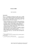
CHAPTER ONE
Introduction
The Digi SYNC/570 and the SYNCY57Oi are high-performance expansion
boards for ISA or Micro Channel computers. The SYNC/570 adds two synchronous/asynchronous serial ports while the SYNW57Oi adds two or four
synchronous/ asynchronous ports. They are designed for applications
requiring cost-effective communications. Each board and connector
package is supplied with all the hardware and software needed for a
complete board installation.
The Hitachi HD64570 Serial Communications Adapter WA) provides a
highly-integrated advanced communications subsystem for the SYNC/570
and the SYNW57Oi. It further maximizes synchronous communications
performance by using protocol-specific features to minimize driver
overhead.
The onboard memory of both the SYNC/570 and the SYIW57Oi is directly
addressable by both the system and the SCA’s DMA. Program-initiated DMA
transfers operate at DMA/memory speed independently of other system
activity. This architecture provides low system overhead and high
performance.
The optional OEM software lock ensures that OEM software will operate
only with OEM-supplied boards.
SYNW57Oi (and SYNC/570 optionally) includes SurgeBlock”, which is
designed to protect the board and the computer in which it is installed
against damage from data line surges.
SYNC/S70
Multiple SYNC/570 boards may share a common memory window. Micro
Channel boards may also share a common interrupt request line.
The two ports of the SYNC/570 each have a high density DB-15 connector
to connect any device with an EIA-232-D interface to your computer. The
board operates at line speeds from 4800 baud to over 115K.
1
A complete list of SYNC/570 features and specifications is located in the
appendices.
!!xNc/57oi
The SYNW57Oi communicates at Tl/El line speeds up to 5 Mbps. Each
HI64570 chip supports two synchronous/asynchronous ports and four
channels of DMA as well as interrupt and timer logic.
Digi SYNC/57Oi is available with several interface options. Interface specific
information (interface setting instructions, cables, connector information)
can be found in the interface appendices.
Multiple SYNC/57Oi boards may share a common memory window. Micro
Channel boards may also share a common interrupt request line.
t
A complete list of SYNC/57Oi features and specifications is located in the
appendices.
2
Chapter One: Introduction
CHAPTER WO
Protecting Your Equipment and Data
Elect&xl Surge and Power Protection
Lightning, electrical surges, and power fluctuations can damage your equipment and/or data through the power lines and/or the serial data lines. When
electrical storms occur, the most effective method of protecting your computer system is to unplug your computer and peripherals, and disconnect
all data and telephone lines.
To protect against lightning, electrical surges, and power fluctuations, Digi
recommends uninterruptible power supplies CUPS), power line filters, and
surge protectors for every installation.
A UPS can provide protection from electrical surges and fluctuations in the
power supplied to the computer. However, it does little good to protect the
main console if you have no protection on the other devices attached to the
system. Power line filters protect against electrical surges and transient
spikes. Some filters even have a shutdown feature that drops power to the
device if voltage drops below a preset level. This prevents the spikes and
surges caused by the typical “off and on” electrical problems that occur
during a thunderstorm. AC line filters should be used with all electrical
devices connected to a computer system, no matter how small or simple.
The interface cables themselves present another potential danger. Nearby
lightning strikes can induce high-voltage surges into the cables. Machinery,
especially commercial machines with electric motors, often generates electrical noise that can be picked up by cables and cause data errors or
equipment damage. Digi includes SurgeBlock on every SYNCY57Oi and
optionally on the SYNW70. SurgeBlock clips fast-rising peak voltages to
help protect against spikes over twenty-five volts caused by lightning,
static, or induced voltage. For maximum protection we recommend surge
suppressors on the peripheral end of all serial cables.
Cables running long distances and/or through electrically noisy areas are
subject to noise pickup that can cause data errors or equipment damage.
Destructive power surges can also enter through modems via telephone
connections. Filters made specifically for this purpose should be included
on all telephone line connections.
3
Using a receptacle for only the computer and terminal also protects against
data errors or equipment damage. Sharing the receptacle with noiseproducing devices such as fax machines, printers, calculators, and heaters
may allow noise pickup.
Grounding T e c h n i q u e s
Many terminals and computers are dependent on earth ground to set a
reference for signal ground. Improper grounding or differences in ground
potential between your computer and terminals can damage your equipment or even create a safety hazard. Consequently, you should make sure
that every component in your system is properly grounded.
Connect your computer and all terminals and other peripherals to threepronged grounded receptacles, making sure that the receptacles are wired
properly. If you must use three-prong to two-prong adapters, make sure
that the adapter ground tabs are properly grounded.
A proper chassis ground guarantees that no dangerous voltages exist on
terminal frames. Proper grounding also helps cancel noise that can otherwise be induced on the frame or equipment.
Local electrical codes may also dictate special grounding arrangements.
Your electrician can make sure that your installation complies with all
applicable codes. If you have any doubt about the integrity of the grounding system in your location, have the system checked by a licensed
electrician.
Static Protection
Your computer’s case not only houses its family of computer components,
but it also protects these sensitive electronic components from stray magnetic @VII) and electrical WI, static) fields.
&ILL
WARNING
Using pn@er stattc control metboa is esseniial wheneoeryou use, move, or
open ymcr computerfor modifications.
4
Chapter Two: Protecting Your Equipment and Data
Make sure that you are working in a static-controlled area which includes at
least a conductive benchtop mat or chair mat that is electrically connected
to earth ground. Conductive wrist straps in conjunction with ground cords
provide extra protection for handling electronic components. Always store
and/or move individual printed circuit boards in a conductive bag. Consult
your local electronics or office supply distributor for static control products.
If you would like an overview of grounding and static protection theories
and techniques, you can obtain a copy of Federal Information Processing
Standards Publication 94: Gutdel{ne on Ekcttical Power oJALlP Instalhtfons. This booklet is available from the National Technical Information
Service, U.S. Department of Commerce, Springfield, VA ~?161703/4874650.
5
t
6
Chapter Two: Protecting Your Equipment and Data
CHAPTER THREE
Checking Your Package Contents
After opening the shipping box, check the contents.
ALL
Lease the board in ttspmttxti~ anti-static bag until tnstalkatton. When
WARNING
tnstalling or movtng boa&, always use adequutepmautions Gucb as a
groundtng strap) topmmt electrostatic damage.
sMyc/570 Contents:
l SYNC/570 board
l Two, g-foot, DB-15 to DE25 cables
l Loopback connector
l Information packet, including
-User’s manual
-Diagnostic diskette
-Customer Information Packet
SYNC/57Oi Contents:
l SYNC/57Oi board
l One duo-cable for two-port boards or one quad-cable for four port
boards
l Loopback connector
l Information packet, including
-User’s manual
-Diagnostic diskette
-Customer Information Packet
7
8
Chapter Three: Checking Your Package Contents
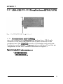
CHAPTER FOUR
Installing the SYNC/570 and SYNC/57Oi
&!L
‘15cm ofl$ower to your cornwet- and disconnect
WARNING
the power cord. Insetttng
a board into the system u&power applied could damage the system, the
board, or both. Such abuse wtll void yrmr warranty.
1.
Remove the cover of the computer (see computer mantiacturer’s
instructions~.
2.
Determine which 16-bit slot your SYNC/570 or SYNC/57Oi will
occupy. Loosen the thumb screw Micro Channel) or remove the
hold-down screw at the top of: the blank card bracket of the slot and
remove the blank card bracket (ISA).
23s are hstalling a
NOTE
SMvU57(H with a jumper selectable h-&$ce, set
the jumpets on the board for the correct inte@ce. Refer to the appendix
pertahtng to your Yetsion of SYiW57Oi for insmttons.
rfrou
SL
JumperJPl con.tnA the Fast select
NOTE
citcuitty on board. Botb the XVU570
and the syNc/57# are shipped wttb ajumper connecting pin 2 andptn 3
ofpI. 7lH.s setttng allows the boara3 to uxxiz with any combination of 8 or
16 btt vtdeo and/or network cards supporting Fast Select. W%enphs 1 and
2 anz jumpered, the board must be h.Mled in a 128KBparagrapb wbicb
contains only 16 bit cards. l’be default setttng @ins 2 and 3 jumpemd)
works tn most computers and should not be changed without veri’ation
from Dtgi Technical Suppott.
3.
If you are installing a SYNC/570 or SYIW57Oi in an ISA computer,
you must configure the I/O address by setting the switch on the
9
board before you install the board. Refer to Section 5 for switch
settings. When you have set the switch, continue with the board
installation below.
If you are installing a SYNC/570 or SYNC/57Oi in a Micro Channel
computer, proceed with the board installation. When the board is
installed, configure it as described in Section 6.
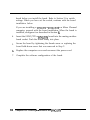
4.
Insert the SYNC/570 or SYNC/57Oi board into the mating motherboard socket. Push the board firmly into place.
5.
Secure the board by tightening the thumb screw or replacing the
board hold-down screw that was removed in Step 2.
6.
Replace the computer cover and reconnect the power cord
7.
Complete the software configuration of the board.
10
Chapter Four: Installing the SYNC/570 and SYNC/570i
CHAPTER FIVE
Setting the ISA SYNC/570 and SYNC/57Oi
Switch
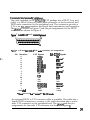
Before installing the SYNC/570 or SYNC/57Oi in an ISA system, set the
multi-segment switch on the board The setting of the switch selects the
starting address of the block of I/O locations which the SYNC/570 or
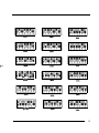
SYNC/57Oi uses. The board is shipped with a setting of 300H. Diagrams of
commonly used I/O address switch settings begin on the following page.
za
NOTE
The memory address and intewpt line @RQI are sojhare con&urable
Ceitber your operating system or an installable drtverj. You will be asked to
@ectfL a 1GKB memory wtndour location.
JE!L
All VO addresses menttoned in this manual are in
NOTE
htxahcimal format.
&!L
Ifvou am installing a SMvcj/5701 that is tnterjhce con&urable, set the
NOTE
jumper on the daugbte&oanI befow conttndng the hstalkztion press.
Refi to the ap~ixpertaintng to your version of SYiW5701 for more
fnformatton.
11
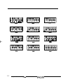
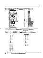
commonly
12
used
r/o Address
switchsewgs
Chapkr Five: Setting the ISA SYNC/570 and SYNC/570i Switch
jPaeerR6l
I2 3
44b
25oH
27OH
13
pwRQQ
1
1
a
4
5
,
34w
1 m m
I -
yaaeRQQ
1
t
a
a
4
I
b
I
I
I -
qRQQQQQ
I
I
a&H
14
Chapter Five: Setting he ISA SYNC/570 and SYNC/570i Switch
3
4
1
4
CHAPTER SIX
Configuring the Micro Channel SYNC/570 and
SYNC/570i
Configure the SYNC/570 and SYNW57Oi through your computers Micro
Channel Programmable Options Select @OS) system, using data from the
Digi Adapter Definition File (ADI on the diagnostic diskette. This system
uses hardware registers, selected and loaded through software, to assign
system resources to an expansion board. Each type of expansion board has
its own unique code number, assigned in conjunction with the computer
manufacturer, which identifies it to the system. <If you cannot determine
the proper setup information, check with an operating system vendor or
Digi Customer Support.)
zE!L
Refer to JQW computer system documentation for informution on the
NOTE
Programmable Option Select.
-
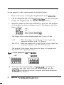
1.
Install the board as described in Section 4.
2.
Determine which ADF file on the Digi Diagnostics Diskette you need
for configuration. Refer to the note below for an explanation of the
files. If necessary, copy and rename the file you need.
NOTE
,q
The diagnostics diskette actually contatns tbme ALIFfiks: @6163.AD4
@6163.4X, and @6163.AD2. Thefiles @GlG3ADF and @6163ALIl are
tahticaL clots ADFCple is the one that b copied to your reference dtskette.)
i%e ADF and AD1 flks contain the most commonly used con_f&urations.
The @6163ALI2jIk contains everypcxslbk option for conflguratlon.
Isyou wish to use the AD2Jile, you must copy thefile to the wfmnce
diskette as @6163_ALIF. Since the reference dtikette will copy only the ALIF
fire, copy tbeji’le to another diskette and rename tt ALIF.
15
f
3.
Reboot the computer with the backup copy of your computer
system’s reference diskette. The computer will show error 165 and
beep twice. Continue as instructed.
4.
Follow the instructions shown on the screen to select the mode
necessary to manuaIly set the configuration--do not use the automatic amfIguration. (The instructions for manual configuration will
vary for computers ma& by different manufacturers.)
s.
When you are prompted to copy the new adapter files, insert the Digi
Diagnostics Diskette.
6.
Press ENTER. The computer will read the @6163.ADP file.
7.
At the prompt, remove the diagnostics disk and reinsert the reference
diskette.
8.
Press ENTER. The file @6163ADF copies to the reference disk.
9.
Follow the instructions shown on the screen to set or change the
configuration for the Digi SYNC/570 or SYIW57Oi.
10.
Select the I/O address, memory address, and IRQ from the list of
addresses and interrupt lines shown.
11.
Follow the instructions to save the configuration you have chosen
and to exit the program.
12.
Remove the copy of the reference diskette.
lb
Chapter Six: Configuring the Micm Channel SYNC/570 and SYNC/570i
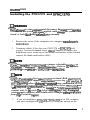
CHAPTER SEVEN
Connecting Peripherals
Your application may specify the cable configuration required for
connecting modems to a computer. If so, you should follow their recommendations. If cable configuration is not specified, you can use the cable
type described in the appendix pertaining to your version of SYNC/570 or
SYNC/57Oi.
If you supply your own cables for SYNC/570 or SYNC/57Oi, Digi
recommends shielded cables (15 pF or less capacitance per foot) for all
installations. The FCC requires the use of shielded cables to comply with
EMI/RFI emission limits. In addition, cables that run long distances or
through electrically noisy areas are subjjct to voltage surges that can cause
data errors or equipment damage.
t
EIA-232-D specifies a maximum cable length of 50 feet. If you run cables
farther than 50 feet, you increase the risk of surge damage and data loss.
(However, using shielded cable of lo-15 pP capacitance per foot somewhat
lessens the risk of data errors.>
zE4
W%en muting
NOTE
your cables, do not run them parallel to AC wiring or on top
ofjluomcen# igbt ballasts. BunaYfng several EIA-232-D cables together fs
acceptable.
Refer to the appendix pertaining to your version of SYNC/570 or
SYNC/57Oi for cable and connector information.
17
f
18
Chapter seven: Connecting Periphemls
CHAPTER EGHT
Using the Diagnostics Disk
The diagnostics diskette in conjunction with the loopback connector is
designed to verify correct installation. Make a copy of this disk and
store the originaL Should a problem develop in the future, you can
run the diagnostics to locate the problem.
ZEL
Your system must be runntng DOS in order to use the diagnwicsprogram.
NOTE
The diagnostics tests one board at a time. Although the active board by
default is the ISA board at the highest I/O address or the Micro Channel
board at the highest slot number, you may change the active board. The
screen header indicates the active board and its address.
t
The tests will fail if there is an address or interrupt conflict If the
diagnostics cannot determine your switch settings, there is probably a
conflict. In this case, try other address and/or interrupt settings.
For an ISA system, the diagnostics program displays IRQ, the base memory
address, and the base I/O address. You may modify the address and IRQ
selections from the diagnostics. The IRQ must be active, and you must
select a non-zero address. If you cannot determine a setting, call Digi
Customer Support for assistance.
For a Micro Channel system, the diagnostics program displays the current
POS registers which identify the IRQ, the base memory address, and the
base I/O address. If any of these parameters need to be changed, repeat
the procedure in Section 6 beginning with Step 3 on Page 16. If you cannot
determine a setting, call Digi Customer Support for assistance.
1.
Insert the diagnostic disk into Drive A.
2.
+Iype ArSYNCS70 to start the diagnostics.
3.
Follow the instructions on the screen.
19
When IRQ and address selection are acceptable, the adapter memory
is tested. ‘Ihe test does write/verify at every location with word
accesses only. Each 16K memory window is selected and tested
independently. Address and data buses are tested separately.
The program then runs a window uniqueness test. A different, single
word is written to each of the eight 16K windows; then the test reads
each window to verify that the windows are indeed unique.
When prompted, install the single channel loopback connector onto
line 1 (the lower connector for Micro Channel). The wiring diagram
for the loopback connector is in the appendix pertaining to your
version of SYNC/570 or SYIW57Oi. The diagnostics program tests the
control and data lines. The control line loopback tests RI’S to CTS,
and DTR to DSR to DCD. The data loopback test is the default single
channel chained-block DhL4 transfer mode test. When the line 1 tests
are complete, install the loopback connector on line 2 (the upper
connector for Micro Channel). The tests will be repeated for line 2.
The diagnostics program also tests the ability of the card to generate
interrupts by way of internal data loopbacks. It tests all found ports.
For example, a 4 port board will prompt you to move the loopback
connector when performing the external data and control signal tests.
The internal and external tests are run at the maximum supported bit
rates for their respective interfaces. On the internal tests, all available
channels are run simultaneously at the maximum bit rate to help
resolve arbitration and memory bandwidth issues.
20
Chapter Eight: Using the Diagnostics Disk
CHAPTER NINE
In Case of Trouble
BL
WARNING
Make sum your computer 13 turned off befom hstalltng or nvrwuing
boar& When installhzg or removing boards, always use adequuteprecautions b4ch as a grvunding strap) top- electnxtattc damage.
Test your SYNC/570 or SYNC/57Oi using the diagnostics disk provided If
the SYNC/570 or SYNW7Oi passes all the tests, the problem is probably
elsewhere. The symptoms of particular problems may vary between
operating systems. Common problems are listed below.
Addxess/Interrupt conflicts
All devices in your system must have unique addresses that must not
overlap. The memory location must be outside the caching memory
range. If you think you have a conflict problem, try alternate settings.
Inconsistent Baud Rate
The baud rate and other parameters chosen via the operating system
must be the same for the SYNC/570 or SYNC/57Oi and the peripherals
connected to it.
No Handshaking Signals
Some peripheral devices may need some or all of the handshaking
signals that SYNC/570 or SYNW57Oi supports.
Iucomplete or Incorrect Iustallation
Some operating systems require that an installation procedure be run
before SYNC/570 or SYlW57Oi is recognized Refer to your operating
system user’s manual. Verify correct SYNC/570 or SYNW57Oi hardware installation.
21
Improper Grounding
Make sure that every component in your system is properly grounded.
Differences in ground potential between your computer and terminals can
damage equipment.
If your board fails the diagnostics or you are unable to isolate the problem,
call Digi Technical Support @OO-344-4273) anytime between 8 a.m. and 6
p.m. Central Time (Monday through Friday). We can give you suggestions
for things to try. Please have the following information ready when you
call:
Fill in information here
.
.
.
.
t
.
.
.
.
.
.
.
22
Computer make
Computer model number
Operating system
Which Digi board you are using
Serial number
Revision number
Type of hard drive in your system
Type of video card in your system
Type of tape backup in your system
Failure symptoms
Results of diagnostics
Whether the board has worked before
(was it installed successfully?)
Dealer/store where you purchased
your Digi board
Chapter Nine: In Case of Trouble
IfYou Have
to Return
a Board
Sometimes our boards do have problems and have to be returned for service. In this case, you’ll need to call us for an RMA number. You must have
an RMA number to return a board to Digi. The RMA number must appear
on the outside of the package. Before calling for the number, make sure
you can answer the following questions:
t-
1.
Where did you buy your board? If you bought from a dealer, you
should go through the dealer to return the board. If you bought it
from Digi, you can deal directly with us for repair.
2.
What is your boards serial number, revision level number, and date
of purchase?
3.
Have you followed the checklist at the beginning of this section and
tried all of the steps? We’ve found that these procedures eliminate
most problems encountered during installation.
4.
Have you contacted the dealer from whom you originally purchased
the board for his advice and assistance?
Your Digi board is one of the most reliable parts of your multiuser system.
As a matter of fact, if you purchase a board from us and it doesn’t work in
your application, or if you decide not to keep it for any reason during the
first 30 days, we will refund your money. But remember, we’re here to help
in any casecause our ultimate goal is to keep your system up and
running, and to keep you a satisfied customer.
23
24
Chapter Nine: in Case of Trouble
APPENDIX A
SYNC/570 Host Adapter EIA 2321) Interface
The SYNC/570 has two high density 15pin D-subminiature female port
connectors. The connectors provide an EIA 232D interface and serial data
transmission and reception.
Your application may specify the cable configuration required for
connecting modems to a computer. If so, you should follow their recom-.
men&&ions. If cable configuration is not specified, you can use the cable
types discussed below. Cables for use with synchronous modems need a
minimum of eleven wires plus a shield.
DB-15Connectors~Cabllng
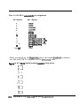
The DB-15 connectors are compatiile with HA-232-D devices. Figure 1
shows the pinout and pin assignments for the DB-15 connectors on the
SYNW570.
Figure 1, SYNC/570 DB-15 female connector and connector pin asgnments
\3?jj$$)6
1
2
3
Not connected
Tmnsmitbd Data (TXD)
RacoiiDakJ(RxD)
15
6
7
8
12
13
DataSetRwdy(DSR)
SignalGmund
DakCuniwDetect(DCD)
ReceiiUock(RXC)
Tmnsmit Cbck (TXq
14
15
shell
TmnsmitCkekfTX~
DanTwminalReady(DTRj
CGND
Gwt
WJt
byut
Input
%&
The cables included in the SYNC/570 package have a DB-15 male connector
on the board end, and a DE25 male connector on the peripheral end. The
pinout and pin assignments for the DB-25 connector are shown in Figure 2.
25
-
Figure 2, Cab& 08-25 male conneckr and cannector
1
2
3
4
5
6
7
8
17
24
15
20
shell
pin assignmenI5
Notcumecbd
Tmnsmitbd Data (TXO)
-m(RxD)
5igmlGmund
Data Cmior Debct (DCD)
ReceimClock(RXCl
Tmnunit Cbck (TXC)
Tmnsmit Cbck (TXC4
Data Tuminal Ready (DTltj
CGND
When prompted by the diagnostics, insert the male loopback connector
into the female DE15 connector on the SYIW570.
F&u 3,5YNC/570 D&l 5 male bopbak connector wiring diimm
3
6
8
15 3
26
&pendix A: SYNC/570 Host
Adapter
EIA-232-D Interface
APPENDIX B
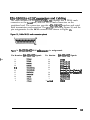
V.35/EIA-232-D Daughterboard (SYNC/57Oi)
Fiium 5,5YNc/57oi 4-Port, v.35 daughkriloald
Jumper Setdng for Interface Selecdon
Before installing the SYNW57Oi in your system, make sure the jumper
block on the board is set for the correct interface - EZA-232-D or V.35.
za
WARNING
When disconnecting the &ughte&oard in order to set the jumper, use
adequateptvcautions (such as a grounding w&t strap that is connected to
earth gnnuad) toprwent electrostatic damage.
27
Set the jumpers for the correct interface as described below.
1.
Remove the screws securing the daughterboard to the SYNC/57Oi.
2.
Pull the daughterboard from the SYNU57Oi. mere are two connectors
holding the daughterboard. Do not use a twisting motion.)
3.
Install the jumper for the correct interface for each port. The positions
of the jumpers are shown in Figures 4 and 5. The jumpers control the
lines as follows:
line 1
JPI-Jp5
line 2
JPG-JP 10
line 3 (4 port board only)
JPll-JPl5
line 4 (4 port board only)
JP16-JP20
The jumper block on the daughterboard has 3 rows of 5 pins.
v.35
EIA-232-D
When the jumpers are on the top 2 rows of pins, the
connectors interface with V.35 devices.
When the jumpers are on the bottom 2 rows of pins, the
connectors interface with EIA-232-D devices.
The position of the jumper block shown in Figure 6 is upright with
the small 1 at the upper left comer.
Fgure 6, lumper positions for V.35 and E&232-D
v.35
4.
28
-
EIA-232-D
Reconnect the daughterboard to the SYNW57Oi by matching the
connectors and screw wells. Push the daughterboard onto the
SYNC/57Oi and replace the screws. Continue with board installation
as described in Section 4.
Appendix B: V.35/EL4-232-D Daughterboard
CoMectors
and c*ling
The cable included in the SYNW7Oi V.35 package has a DB-37 (two port
cable) or a DB-62 (four port cable) male connector on the board end, and
DE25 male connectors on the peripheral end. The connectors provide a
V.35 or an E&232-D interface and serial data transmission and reception.
The pinout is shown in Figure 7 and the pin assignments for the DB-25
connector are shown in Figure 8.
Fiium 7, cable D6-25 male conneckr
pinout
Fiium 8, V.35 and EIA-232-D DE25 male connector pin assignments
Pin Number
t
2
14
3
16
15
12
17
9
4
5
20
6
8
24
11
7
1 and rhoI1
V.35 Signals
EIA-232-D Signals
TxD(Bl
R)WJB)
~tJJGN(ry
J’X-tNtRI
wcu(w
mQK(Rt
RTS
CrS
DTR
DSR
DCD
lXCLKOUT(Aj
~CUKMtIlR)
GND
CGND
l%D
lmuved*
RXD
lucend’
lxClN
Nnmd*
RXC
rmold*
RTS
CTS
DTR
DSR
DCD
TXCOUT
rmowmd*
GND
CGND
’ &so pins must k ‘no conno& in EIA-232-D mode.
An optional DB-25 to V.35 converter cable is available. The cable has a
female DB-25 connector to connect to the cable described above and a
male V.35 connector on the peripheral end. The pinout and the pin
assignments for the male V.35 connector are shown in Figure 9.
29
Fgun 9, C mmier cab40 V.35 male camector p’bout and pin as+mmts
0
0
0
P-A
@-.C
Z-O-. E
0
o--H
0
0
0
0
0
w0-L
0
0
0 0 0 0
0
0
0
0
0
0 0
01
CGND
GND
RTS
CTS
DSR
DCD
A
B
C
D
E
F
H
P
R
S
T
U
V
W
X
%I
TXDIsl
RxD(BI
TXCtJCOUT[cy
RXCwAl
TXClKOUT(Bj
RXCU@I
When prompted by the diagnosics, insert the female loopback connector
into the male DB-25 connector on the SYNW7Oi cable.
Figurn 10, V.35 and EIA-232-D DE25 female bopback connector wing diimms
v.35
EtA-232-D
cl
Kl
457
457
:
20 3
lz
El
30
Appendix 0: V.35/EIA-232-D Daughterbowd
:
20 3
APPENDIX C
X.2 1 /EIA-530 (EIA-422) Daughterboard (SYNC/57Oi)
x.21 coMecmrsandcabuflg
The cable included in the SYNW57Oi X.21
package has a DB-44 male
connector on the board end, and two DB-15 male connectors on the
peripheral end. The connectors provide a X21 interface and serial data
transmission and reception. The pinout is shown in Figure 12 and the pin
assignments for the DB-15 connector are shown in Figure 13.
Fgum 12,CabkDB-15makconnechx pinout
31
Fiiun 13, X.21 DB-15 male conmcbr pin assignments
Pin Number
2
9
3
10
4
11
5
12
6
7
13
1 4
a
1 and rholl
X21 Signals
WB)
InhdiihW(B)
S@d Elommtllmi~ In W
Bi~nd Eknmt TiinB Gut W
Bi~nal Ebnont Tiing In (B)
Biinal Eland liin~ Gut(B)
Sinal Ground
CGND
When prompted by the diagnosics, insert the female loopback connector
into the male DB-15 connector on the SYNC/57Oi cable.
Fiiure 14, X.21 DE1 5 female bopback cormscbx wiring diimm
xl
3
5
32
7
Appendix C: X.21 /E&530 (EIA-422) Daughterboard
EIA-530 (EIA-422) Connect0rsandcabling
The cable included in the SYNC/57Oi JZIA-530 package has a DB-44 male
connector on the board end, and two DB-25 male connectors on the
peripheral end. The connectors provide a E&530/422 interface and serial
data transmission and reception. The pinout is shown in Figure 15, and the
pin assignments for the DB-25 connector are shown in Figure 16.
Fiiurr, 16, EIA-530/ElA-422 DE-25 male connechx
Pin Number EIA-SO/422 Signals
t
2
14
3
16
15
12
17
9
19
4
5
pin assignments
Pin Number
13
20
23
6
22
B
10
24
11
7
1 andshall
EIA-5301422 Signals
WB)
DlER-+W
D1ERadyON
=WW
=R-JY(B)
RdV@dUllOSlpllDhChWW
Raalvad Uno Siinal Dotatar (6)
TXClKOlN(Aj
TXClKOUT(B)
SignaiGmund
CGND
33
When prompted by the diagnosics, insert the female loopback connedor
into the male DB-25 connector on the SYNW7Oi cable.
Fiium 17, EIA-530/422 D&25 fmab bopback connector wiring diimm
t
34
I
Appendix C: X.2 1 /EIA-530 (EIA-422) Daughterboard
APPENDIX D
SYNC/570 Features and Specifications
l
Hitachi HD64570 Serial Communications Adapter (SCA)
l
‘I’wo EIA-232-DC serial ports
l
Line speeds to lK)Kb/second
l
Full modem control
0 Four DMA channels for full duplex operation
l
128KB onboard shared memory &i-stated)
l
16KB shared memory window
l
Software configurable
l
T&state IRQ logic for Micro Channel
l
16-bit ISA and Micro Channel @S/2 and RS/6000)
. OEM software lock
. Optional SurgeBlock surge protection
35
specifications:
USART:
Memory:
Shared Memory Window:
Serial Ports:
Cabling:
EIA-232-D Modem Signals:
Connectors:
USART:
Baud Rate:
DMA:
Programmable Timers:
VO Address:
PC Interrupts:
Diagnostics:
Power Requirements:
Operating Temperature:
Relative Humidity:
Certifications:
SurgeBlock:
36
Hitachi I-ID64570 Serial Communications
Adapter 1OMhz
128KB Dual-Ported (tri-stated)
16KB (assignable within first 16~~ of system
memory)
Two EIA-232-D
Two DB-15 (male) to DB25 (male) 8 ft. cables
TXD, RXD, CTS, RTS, DSR, DTR, TXC, RXC, DCD
Two DB-15 Female (High Density)
Hitachi HD64570 Serial Communications
Adapter (XX)
Up to 5 Mb/second each line
Four channels (Hitachi HI%45701
Hitachi HD64570
ISA - hardware switch configurable
Micro Channel - software configurable
3,5,7, 10, 12, 15 (software configurable>
DOS-based
75OmA@+5vDC
4OmA@+/-12vDC
lo-55O c
5-90%, noncondensing
FCC Class A
Optional
Appendix D: SYNC/570 Features and Specificationr
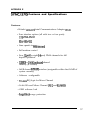
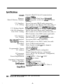
APPENDIX E
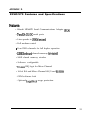
SYNC/570i Features and Specifications
Features:
Hitachi I-ID64570 Serial Communications Adapter (SCA)
l
l
Four interface options (all with two or four ports):
V.35/EW-232-D
x.21
JZIA-530/422
l
Line speeds to SMb/second
l
Full modem control
l
l
l
Four (2 port> or eight (4 port) DMA channels for full
duplex operation
128KB or 256~~ onboard shared
memory (u-i-stated)
16KB shared memov window (assignable within first 16MB of
system memory
l
Software configurable
l
T&state IRQ logic for Micro Channel
l
16-bit ISA and Micro Channel (PS/2 and RS/6000)
l
OEM software lock
l
SurgeBlock surge protection
37
Specifications:
USART:
Memory:
Shared Memory Window:
V.35 Interface:
V.35 Cabling:
V.35 Modem Signals:
Hitachi I-ID64570 Serial Communications
Adapter 1OMhz
12fKB or 256KB Dual-Ported &i-stated>
16~1.3 (assignable within first 16~~ of system
memory)
Two or four ports (DB-25 male connectors)
DE37 (male) to two DB-25 (male) duo-cable, or
DB-62 (male) to four DE25 (male> quad-cable
T)(D+_, RX& CIS, R’IS, DSR, DIR, TX& IUQ, DCD
EIA-232-D Interface: Two or four ports (DE25 male connectors)
EIA-232-D Cabling: DE37 (male) to two DE25 (male) duo-cable, or
DB-62 (male) to four DE25 (male) quad-cable
X.21 Interface: Two ports (DB-15 male connectors~
X.21 Cabling: DB-44 (male) to two DE15 (male> duo-cable
E&530/422 Interface: Two ports (DE25 male connectors)
E&530/422 Cabling: DB-44 (male) to two DB-25 (male) duo-cable
Baud Rate:
DMA:
Programmable Timers:
I/O Address:
PC Interrupts:
Diagnostics:
Power Requirements:
Operating Temperature:
Relative Humidity:
CertiEcations:
SurgeBlock:
38
Up to 5 Mb/second each line
Four (2 port) or eight (4 port) channels
(Hitachi HD64570)
Hitachi HD64570
ISA - hardware switch configurable
Micro Channel - software configurable
3, 5, 7, 10, 11, 12, 15 (software configurable)
DOS-based
1.5A @ +5 VDC, 125mA @ -5VDC
4OmA@ +/- 12VDC
lo-55O c
5-!90%, noncondensing
ISA SYNC/57Oi - FCC Class B
MicroChannel SYNC/57Oi - FCC Class A
Optional
Appendix E: SYNC/570i Features and Specifications