
1
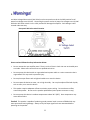
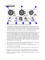
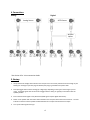
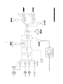
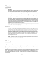
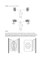
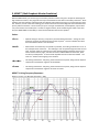
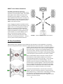
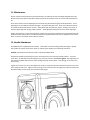
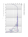
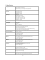
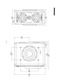
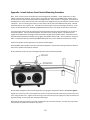
Owner’s Manual Contents page Description Warnings! (please read carefully) Inputs and Controls Connections Startup Signal Flow Diagram Protection Positioning MEME™ Voicing Force Cancelation Maintenance Handle Attachment Frequency Response Specifications Drawings Warranty Appendix : Stand Mounting 01 02 03 04 04 05 06 06 08 09 10 10 11 12 13 14 15 1. Description The MicroMain27 Gen2 is a 3.5-way active loudspeaker capable of nearfield, mid-field and far-field operation. The five drive units are all housed in sealed enclosures. The DSP controlled four-way power amplifier module can deliver 500 Watts continuously. The system accepts either analog or 24 bit/192 kHz digital audio signals. Cutting edge MEME™ (Multi Emphasis Monitor Emulation™) technology enables the MicroMain27 Gen2 to model the frequency, phase and transient responses, dynamic compression, distortion signature and overall translation characteristics of classic studio monitors. 1 2. The Mains Voltage Select switch (VAC Select) on the rear panel must be in the 230V position for AC power line voltages over 132 VAC. Connecting the power cord to AC power line voltages over 132 VAC while the VAC Select switch is in the 115V position will damage the amplifier. Such damage is NOT covered under warranty. Rear panel VAC Select switch location Please read and follow the safety information below: Do not remove the rear amplifier panel. There is a risk of electric shock. No user serviceable parts are inside. Please refer service issues to a qualified technician. Do not operate this device with an ungrounded mains power cable or a mains connection that is ungrounded. This may result in personal injury. Do not place open flames such as lighted candles on or near this device . Do not expose this device to water, rain or high humidity. Do not place objects filled with liquids, such as vases, on or near this device. This speaker requires adequate airflow to maintain proper cooling. Do not obstruct airflow around the speaker. Do not run the speaker upside down (mains power connector on top). Do not operate this device in ambient temperatures above 30°C (85°F). Over-temperature may cause device failure. Caution! This speaker is capable of producing sound pressure levels in excess of 85dB which may cause permanent hearing damage. Always verify that input signal levels are attenuated before powering on the speaker. 2 3. Inputs and Controls 1. [INPUT] Toggle switch selects between the analog (A) and digital (D) inputs. 2. [ANLG] XLR connector is designed to receive analog balanced line level audio signal from sources such as preamplifiers, sound cards, monitor controllers and mixing consoles. Pin 1 is tied to chassis ground. Pins 2 & 3 are fully floating differential inputs. Pin 3 must be referenced to ground for single ended input signals. The analog signal is converted to 24bit/192kHz digital audio via a precision, ultra-high-fidelity analog to digital converter section inside the MicroMain27 Gen2. 3. [AES3] XLR connector is designed to receive digital AES3 standard audio signal from sources such as sound cards and digital audio workstations (DAW). The digital signal must be attenuated at the source (“In The Box”). Caution: Non-attenuated digital audio will produce very high sound pressure levels that can potentially damage your hearing and/or the speakers. Each AES3 XLR carries both left and right audio signals. For stereo or multiple speaker operation the monitor output signal must be assigned to two or more AES3 output XLRs within the DAW. Otherwise, a passive AES splitter or an active AES distribution amplifier is required to deliver signal from a signal from a single AES output XLR. Use the CHNL switch on the back of each speaker to select appropriate left or right audio signal from the stereo AES signal. 4. [CHNL] Toggle switch selects between the left (L) or right (R) channel coming from the AES3 data signal. This switch is only active when the INPUT toggle is in the (D) position. 5. [LEVEL] Eight position rotary switch adjusts the level of both the Analog and Digital inputs in precise 1dB increments from +3dB to –6dB. 6. [SUB] Three position toggle switch adjusts the level of the subwoofers from 0dB to +2dB or –2dB. 7. [VOICE] 3.5mm stereo phone jack for connection to MEME™ Selector Switch. See Section 9 for MEME™ setting s and connection details. The default setting with no switch connected is Flat. 8. [USB] The universal serial bus connector is for factory adjustments and calibrations. This connector is NOT an audio input. 3 4. Connections Analog: Digital: Analog Source AES3 Source AES/EBU Splitter * See Section 9 for Voice connection details. 5. Startup 1. Verify that the AC Voltage select switch on the rear panel is in the correct position for the AC voltage in your facility (see warnings on pervious page for details) then plug in grounded mains power cable. 2. Set Input toggle switch to either analog (A) or digital (D) depending on the type of source signal you are using. For digital signals also set the Channel toggle switch to left (L) or right (R) in accordance with the speaker position. 3. Ensure that the audio signal is fully attenuated (AES3 signal requires digital attenuation). 4. Power on the speaker with the rocker switch located on the rear panel above the mains connector. The LED indicator on the front of the speaker will illuminate Red for a couple of seconds then turn Aqua. 5. Turn up the audio signal and enjoy! 4 24bit/192kHz Receiver 24bit/192kHz ADC INPUT 6. Signal Flow Diagram ANLG AES3 CHNL LEVEL Input Level Crossovers and MEME™ VOICE Sub Level SUB 5 Limiters Amplifiers Clip LED MEME™ Voice Selector Switch DACs Tweeter Midbass Midbass Sub Woofer 7. Protection Limiters Peak Limiter The Subwoofer, Midbass and Tweeter channels have individual Peak Limiters designed to protect each driver from high amplitude, short duration audio input signal spikes that might cause damage due to over excursion of the voice coil. These limiters are implemented digitally within the DSP in such a manner that they have zero effect on the audio signal below their thresholds. The front LED indicator light will flash RED when a Peak Limiter on any of the driver channels is triggered. The duration of such events is only a fraction of a second. Therefore, the LED flash may appear pink or orange as the eye naturally blends the normally aqua-blue color of the LED with the red. RMS Limiter The Subwoofer, Midbass and Tweeter channels have individual RMS Limiters designed to protect each driver from long duration, high amplitude audio input signals that might cause thermal damage due to the voice coil. These limiters are implemented digitally within the DSP in such a manner that they have zero effect on the audio signal below their thresholds. The front LED indicator light will flash RED when a RMS Limiter on any of the driver channels is triggered. Caution: Signals large enough to trigger any of the limiters can generate very high sound pressure levels that may result in permanent hearing damage. Over Current In the event of a large audio input signal that might damage the amplifiers or power supply due to current overload, the power supply is designed to enter into Over Current protect mode. This state typically results from a large, broadband input signal burst that flat lines the limiters on all four channels simultaneously. While the fault persists the amplifier power rails shut down, the speaker goes quiet, and the front panel LED turns red. Once the audio input signal is turned down the speaker should reboot within a few seconds. If the speaker fails to reboot or the LED light goes out completely, disconnect the audio input cable and power cycle the speaker. Verify the signal level is attenuated before reconnecting audio input cable. Caution: Signals that cause Over Current protection to trigger can generate very high sound pressure levels that may result in permanent hearing damage. 8. Positioning The acoustic center of the MicroMain27 Gen2 is located at the center of the tweeter. The MM27 Gen2 is designed to work equally well as a nearfield or mid-field monitor. The minimum recommended listening distance is 1 meter (39.4”). While speaker positioning can sometimes be dependent on the nature of the room, a good starting point is to create an equilateral triangle between the two speakers and the listening position. The speakers should be angled inward approximately 30 degrees so the tweeter axes aim towards the listener’s ears, crossing a few inches behind the head. When the speakers are standing vertically, the “Barefoot” text on the front faceplates of both speakers should be on top. When the speakers are turned on their sides to the horizontal orientation, the “Barefoot” text on the front faceplates should be towards the outside. This places the ’bottom’ midbass drivers towards the center of the stereo field. 6 Example: Symmetrical stereo arrangements. BAREFOOT text BAREFOOT text Cooling While the Hypex amplifier modules that drive the MicroMain27 Gen2 are a very efficient, the speaker still generates a significant amount of heat that must be dissipated. This heat is transmitted to the air via the rear amplifier plate, heat sink and the subwoofer cones. In order to ensure proper airflow, a minimum of 5” (127mm) clearance should be maintained between the speaker and any large obstructions. An ambient temperature below 30°C (85°F) should be maintained. Over-temperature may cause speaker to overheat and shut down. 7 9. MEME™ (Multi Emphasis Monitor Emulation) With the MM27 GEN2, you can box up your secondary reference monitors for good. Despite the advantages of high-resolution monitors, many engineers still rely on their NS10s and mix cubes as secondary references. These speakers have long traditions and people find them familiar and useful for focusing in on certain aspects of their mix. However, it's also a fact that crowding your console with those extra boxes degrades the sound field of the primary reference monitors. Not to mention, they are no longer manufactured, need amplifiers, require cable runs, and consume more studio space. To offer an elegant solution, while streamlining the studio at the same time, the MM27 GEN2 has the ability to sound and translate like those classic speakers. Voices: Flat - Optimal setting for accuracy, transparency and outstanding translation. Setting has a flat Hi-Fi - While it does not emulate any one speaker in particular, this setting is indicative of “hi-fi” in OldScl - This setting emulates the frequency, phase and transient response, along with the dynamic Cube - This setting emulates the frequency, phase and transient response, along with the dynamic frequency response and extremely fast transient response. This is the default voice when the Voice Selector Switch is not connected. the colloquial sense of the term. The midrange is a bit scooped and highs are little accentuated. The bass response is altered to have less damping yielding a hybrid character somewhere between the fast, tight, articulate sound of a sealed cabinet and the slower, fatter sound of a ported speaker. A touch of tube amplifier warmth has also been added. The result is a sweeter more forgiving sonic character. compression and distortion signature of the NS10M. compression and distortion signature of classic mix cubes. MEME™ Voicing Frequency Responses: dB SPL at 1 meter, -15 dBV input (attenuator = 0db) 8 MEME™ Voice Selector Connection: The MEME™ Voice Selector switch box is connected to the Voice jack of the speaker via any standard 3.5 mm stereo phone cable. The included 6-way splitter can be used to control the Voice Emulation of up to 5 speakers. Furthermore, the input impedance of the Voice jack is very high. So, additional splitters can be daisy chained in order to control virtually any number of speakers with the MEME™ Voice Selector switch. Caveat: Plugging the speaker into different mains outlets can potentially cause erratic behavior in the MEME™ control. The safety grounds of different outlets can sometimes have ground potential differences of a few volts of more. The resulting voltage spread between the grounded chassis of various speakers can cause the MEME™ control inputs to read incorrect settings or become unstable. Care must be taken with the studio mains power and safety ground layout. If this is a concern, please consult a qualified electrician. Example: 5 channel MEME™ Voice control layout. 10. Force Cancellation Cabinet vibrations are a significant source of distortion and coloration in most loudspeakers. The primary mechanism that generates cabinet vibrations is simple Newtonian action and reaction. As the driver motor (magnet and voice coil) forces the cone to move back and forth in order to generate sound, the cone exerts an equal and opposite force on the motor. This force is transmitted through the driver frame to the cabinet, vibrating the cabinet walls and coloring the sound emitted by the cone. This effect is most especially prevalent in the low frequency drivers where the cone motion is greatest. While, the MicroMain27 Gen2 is built with a massive and well braced cabinet, we also tackle the problem at its source by eliminating vibrations before they even begin. This is achieved through our innovative force cancellation design. The low frequency drivers are mounted on opposing sides of the cabinet and their motors are locked together. As the cones are driven in and out in opposite directions the forces exerted on the motors cancel one another. The vibrations never make it to the cabinet because they are not allowed to develop in the first place. This layout has further benefits. Since the drivers are locked together, the motors and frames function as a massive internal metal cabinet bracing. And because the wavelengths generated by the subwoofers are much larger than the speaker cabinet dimensions, the subs radiate as if they were a single point source located on axis with the tweeter. 9 11. Maintenance Exterior surfaces of this product may be cleaned using a non-abrasive lint-free cloth lightly damped with water. Disconnect the mains power cable when cleaning to avoid risk of electric shock. Do not use alcohol-based cleaners. Driver active surfaces such as diaphragms and surrounds may be cleaned using dry soft bristle brushes. Driver diaphragms are very delicate and easily damaged. So proceed with great care. Clean new sable artist brushes or cosmetic brushes work well for this task. Gently brush dust away from the surface starting at the center of the driver diaphragm and moving radially outward. Avoid applying inward pressure to the driver diaphragm. Repairs, maintenance, or other servicing of this product when its interior compartment is exposed should only be performed under specific advice from Barefoot Sound by a qualified technician or by the Barefoot Service Center. There are no user-serviceable parts inside this product. 12. Handle Attachment Each MM27 Gen2 is supplied with two handles. The handles are useful for lifting and positioning the speaker. The handles can also be used as base “skids” for mounting the speaker in the horizontal orientation. Caution: the handles should never be used to suspend the MM27 Gen2. Attached the handle by positioning it over the mounting holes on the side of the speaker cabinet. Insert the 5/16”-18 x 1.25” flat head screws and tighten using the 3/16” hex key. Do not over tighten! Over tightening can strip out the threaded cabinet inserts and/or damage the finish of the cabinet. Such damage is not covered under warranty. A good way to ensure you do not over tighten the screws is to put the long end of the hex key into the screw and turn it using the short end. Tighten the screw using no more force than you can apply to the short end of the hex key while holding it in the tips of your thumb and index finger. 10 13. MicroMain27 Gen2 Frequency Response dB SPL at 1 meter, free field, -15 dBV input (attenuator = 0db) 11 14. Specifications Analog Input XLR female, Pin 1 ground, Pin 2 positive, Pin 3 negative Input Impedance = 100k Ohms Input Sensitivity (1m) = 90 dB @ -18 dBV (pass band) Analog to Digital Conversion Word Length: 24 bit Sample Rate: 192 kHz Oversampling = 128x Signal/Noise ≥ 125 dB Digital Input XLR female AES/EBU (AES3 standard) Input Impedance = 110 Ohms Word Length: 16,18, 20 or 24 bit Sample Rate: 32 kHz to 192 kHz Signal/Noise ≥ 133 dB Frequency Response 30 Hz - 45 kHz (+/- 3 dB ), 40 Hz - 40 kHz (+/- 1 dB ) Bass Response -3 dB @ 30 Hz Q = 0.707 Slope = 12 dB/octave Cabinet 32 liters total internal volume Sealed subwoofer and midbass enclosures Machined aluminum baffle plate Aluminum subwoofer frames function as lateral cabinet bracing Long fiber wool acoustic damping throughout Crossover Frequencies 100 / 600 / 3000 Hz Tweeter 1" ring radiator with Advanced neodymium motor Rear waveguide chamber Amplifier: 250W Hypex Midbass 1 5.25" poly/paper cone with Advanced neodymium motor +/- 5 mm linear excursion Amplifier: 250W Hypex Midbass 2 5.25" poly/paper cone with Advanced neodymium motor +/- 5 mm linear excursion Amplifier: 250W Hypex Subwoofers 2 x 10" aluminum cone with low distortion motor +/- 13 mm linear excursion Amplifier: 500W Hypex Power Mains Voltage Input: 115 or 230 VAC selectable Idle Power Consumption = 30W Maximum Power Consumption = 650 W Weight Speaker: 68 lbs each (31 kg) Shipping: 80 lbs each (36 kg) Dimensions HxWxD Cabinet: 20.5 x 9.5 x 15.5 inches (521 x 241 x 394 mm) Overall: 20.5 x 10.5 x 17.4 inches (521 x 267 x 442 mm) 12 13. Drawing 13 14. Warranty This product is under limited warranty as described in the following conditions. The warranty period commences on the date of purchase from the authorized dealer. Barefoot Sound reserves the right to request your original purchase receipt as proof of the date of purchase. The warranty follows the product and is transferable to any subsequent owner(s) as long as a copy of the original purchase receipt from the authorized dealer can be provided. Electronic components and cabinetry of the product are warranted for a period of three (3) years against manufacturing defect, covering parts and labor for necessary repairs. Moving speaker components are warranted for a period of one (1) year against manufacturing defect. The manufacturer’s warranties are limited to physical defects in the materials, parts and workmanship used in making the product. Misuse, incorrect installation, connection or handling, repairs or modifications performed by unauthorized persons, abnormal conditions, deliberate abuse, damage due to accidents such as power surges, water, fire, or any other are excluded from any warranty claims. In addition, faulty or unsuitable ancillary equipment, accessories, or options are fitted at owner’s risk. Barefoot Sound warrants all service repairs and replacements for 180 days from the date of return to the customer/owner. This warranty specifically excludes unrelated additional defects or failures. Otherwise the same general provisions of the limited product warranties apply. Technical Support and Service For warranty service and assistance, contact the original authorized dealer/distributor to arrange for return and/ or repair of the product. Barefoot Sound will strive to satisfy all service requests in the fastest manner possible. Under the warranty, Barefoot Sound will repair, or at its discretion, replace the product at no charge, provided it is returned (postage paid) to an authorized Barefoot Sound service center. Any shipping or duties incurred are the customer’s responsibility. Products should be returned suitably packaged to protect from shipping damage, or in their original packaging. Barefoot Sound shall be the sole and final authority to determine the validity of all warranty issues. All non-warranty repairs for current products will be charged according to the service repair pricing schedule. Repair prices will either be based on a flat fee for repair or replacement, or will be estimated depending on the repair deemed necessary. 14 Appendix: Sound Anchors Stand Vertical Mounting Procedure Note: There are two variants of Sound Anchor stands designed for the MM27. Earlier models have 1” thick tubular steel mounting brackets. These require 2” long 5/16”-18 screws to fit the MM27 Gen2. Newer Sound Anchor stands have 0.5” thick solid aluminum mounting brackets. These require 1.5” long 5/16”-18 screws to fit the MM27 Gen2. Please check the size of the mounting screws supplied with your Sound Anchor stands to insure a proper fit. Prior to mounting the stands, turn the screws into the side of the MM27 Gen2 by hand. M8 and 5/16-18 screws are very similar in size. Incorrect size screws will go in a few turns then begin to lock up. If this occurs, contact Sound Anchors, Barefoot ([email protected]) or your dealer for the correct size screws. 1. Test the length of the screws by removing the mounting bracket from the stand and placing it on the side of the speaker cabinet. Line up the mounting holes, insert the screws and finger tighten. The screws should engage the threaded inserts and begin to pull the bracket snug against the speaker cabinet. If the bolts are too long and bottom out before the bracket is snug against the speaker cabinet, STOP. You may have the wrong size bolts. Contact Sound Anchors, Barefoot ([email protected]) or your dealer for the correct size screws. 2. Secure the speaker mounting bracket to the stand at desired height. 3. Attach MM27 Gen2 handles to the side of the cabinet opposite to the side the mounting bracket will attach to. Then set the speaker horizontally on the floor. 4. Tilt stand down and line up the mounting bracket holes with the cabinet bolt holes. 5. Insert bolts and tighten until the mounting bracket is snug against the speaker cabinet. Do not over tighten! A good way to ensure you do not over tighten the screws is to put the long end of the hex key into the screw and turn it using the short end. Tighten the screw using no more force than you can apply to the short end of the hex key while holding it in the tips of your thumb and index finger. 6. Carefully tilt the entire speaker and stand assembly back up so it stands vertically. This step may require assistance because the speaker and stand are very heavy. 15 Barefoot Sound LLC http://barefootsound.com 2013


![Audio Extremes Entertainment [Graffiti Spray User Manual]](http://vs1.manualzilla.com/store/data/005858722_1-74e7fc11dae975c9529a69c83302f350-150x150.png)