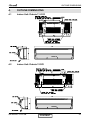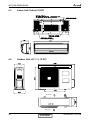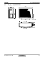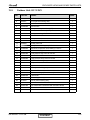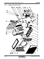
1
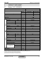
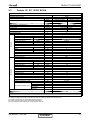
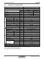
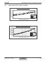
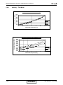
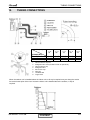
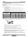
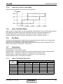
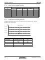
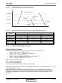
Dakota WDI DCI Series Indoor Units Dakota 7 Dakota 9 Dakota 12 Dakota 18 Outdoor Units GC 7 GC 9 GC 12 GC 18 REFRIGERANT REFRIGERANT R410A SM WDIDCI 1-A.2 GB HEAT PUMP SEPTEMBER – 2008 CONTENT LIST OF EFFECTIVE PAGES LIST OF EFFECTIVE PAGES Note: Changes in the pages are indicated by a “Revision#” in the footer of each effected page (when none indicates no changes in the relevant page). All pages in the following list represent effected/ non effected pages divided by chapters. Dates of issue for original and changed pages are: Original ....... 0 ........ 15 March 2005 Total number of pages in this publication is 79 consisting of the following: Page No. Revision No. # Page No. Revision No. # Page No. Revision No. # Title ....................... 2 A ........................... 2 i ............................. 2 1-1 - 1-3 ................ 2 2-1 - 2-4 ................ 2 3-1 ........................ 2 4-1 - 4-3 ................ 2 5-1 - 5-20 .............. 2 6-1 - 6-4 ................ 2 7-1 ........................ 2 8-1 ........................ 2 9-1 ........................ 2 10-1 ...................... 2 11-1-11-14............. 2 12-1-12-7 .............. 2 13-1-13-11 ............ 2 Appendix -A ...........2 • Zero in this column indicates an original page. *Due to constant improvements please note that the data on this service manual can be modified with out notice. **Photos are not contractual A CONTENT SM WDIDCI 1-A.2 GB TABLE OF CONTENTS Table of Contents 1. INTRODUCTION ...................................................................................................1-1 2. PRODUCT DATA SHEET ......................................................................................2-1 3. RATING CONDITIONS ..........................................................................................3-1 4. OUTLINE DIMENSIONS .......................................................................................4-1 5. PERFORMANCE DATA & PRESSURE CURVES ...............................................5-1 6. SOUND LEVEL CHARACTERISTICS ..................................................................6-1 7. ELECTRICAL DATA ..............................................................................................7-1 8. WIRING DIAGRAMS .............................................................................................8-1 9. REFRIGERATION DIAGRAMS .............................................................................9-1 10. TUBING CONNECTIONS......................................................................................10-1 11. CONTROL SYSTEM .............................................................................................11-1 12. TROUBLESHOOTING ..........................................................................................12-1 13. EXPLODED VIEWS AND SPARE PARTS LISTS .................................................13-1 14. APPENDIX A .........................................................................................................14-1 SM WDIDCI 1-A.2 GB i INTRODUCTION 1. INTRODUCTION 1.1 General The new Dakota DC Inverter split wall mounted series comprise RC (heat pump) models, as follows: ● Dakota 7 ● Dakota 9 ● Dakota 12 ● Dakota 18 The indoor Dakota units are available as LED display types only, featuring esthetic design, compact dimensions, and low noise operation. 1.2 Main Features The Dakota series benefits from the most advanced innovations, namely: ● DC Inverter Technology ● R410A ● Microprocessor control. ● Infrared remote control with liquid crystal display. ● Indoor large diameter cross flow fan, allowing low noise level operation. ● Bended indoor coil with treated aluminum fins and coating for improved efficiency. ● High COP. ● Pre-Charged units up to the max allowing tubing distance. ● Heating operation at outdoor temperature down to -15ºC ● Advanced test and diagnostics mode. ● M2L diagnostics softwear cable port (for PC) ● Easy access to the interconnecting tubing and wiring connections, so that during installation removing the front grill or casing is not necessary. ● Refrigerant pipes can be connected to the indoor unit from 5 different optional directions. ● Automatic treated air sweep. ● Easy installation and service. SM WDIDCI 1-A.2 GB CONTENT 1-1 INTRODUCTION 1.3 Indoor Unit The indoor unit is wall mounted, and can be easily fitted to many types of residential and commercials applications. It includes: ● Casing with air inlet and outlet grills. ● A large-diameter tangential fan. ● Bended coil with treated aluminum fins. ● Motorized flaps. ● Variable Speed motor (PG). ● Advanced electronic control box assembly. ● Interconnecting wiring terminal block. ● Mounting plate. 1.4 Filtration The Dakota series presents several types of air filters: ● Easily accessible, and re-usable pre-filters (mesh) ● Pre-charged electrostatic filter (optional) ● Active carbon filter (optional) 1.5 Control The microprocessor indoor controller, and an infrared remote control, supplied as standard, provide complete operating function and programming. For further details please refer to the Operation Manual, Appendix A. 1.6 Outdoor Unit The Dakota outdoor units can be installed as floor or wall mounted units by using a wall supporting bracket. The metal sheets are protected by anti- corrosion paint work allowing long life resistance. All outdoor units are pre-charged. For further information please refer to the Product Data Sheet, Chapter 2. It includes : ● Single DC Rotary Compressor mounted in a soundproofed compartment ● Axial fan. ● Outdoor coil with hydrophilic louver fins. ● Outlet air fan grill. ● Outdoor advanced controller. ● 2 fan speed AC motor 1-2 CONTENT SM WDIDCI 1-A.2 GB INTRODUCTION 1.7 Tubing Connections Flare type interconnecting tubing to be produced on site. For further details please refer to the Installation Manual, Appendix A. 1.8 Inbox Documentation Each unit is supplied with its own installation and operation manuals. 1.9 Matching Table INDOOR UNITS OUTDOOR UNITS MODEL REFR” Dakota 7 Dakota 9 Dakota 12 Dakota 18 GC 7 GC 9 GC 12 R410A √ √ √ ― GC 18 R410A ― ― ― √ SM WDIDCI 1-A.2 GB CONTENT 1-3 PRODUCT DATA SHEET 2. PRODUCT DATA SHEET 2.1 Dakota 7 / GC 7 DCI R410A Model Indoor Unit Model Outdoor Unit Installation Method of Pipe Characteristics Dakota 7 DCI GC 7 R410A Flared Capacity (1) OUTDOOR INDOOR Power input (1) EER (Cooling) or COP(Heating) (1) Energy efficiency class Power supply Rated current Starting current Circuit breaker rating Fan type & quantity Fan speeds H/M/L Air flow (2) H/M/L External static pressure Min-Max Sound power level (3) H/M/L Sound pressure level (4) H/M/L Moisture removal Condensate drain tube I.D Dimensions WxHxD Weight Package dimensions WxHxD Packaged weight Units per pallet Stacking height Refrigerant control Compressor type, model Fan type & quantity Fan speeds H/L Air flow H/L Sound power level H/L Sound pressure level (4) H/L Dimensions WxHxD Weight Package dimensions WxHxD Packaged weight Units per pallet Stacking height Refrigerant type Refrigerant chargless distance Additional charge per 1 meter Liquid line Suction line Connections between units Max.tubing length Max.height difference Operation control type Heating elements Others (1) (2) (3) (4) Units Btu/hr kW kW W/W V/Ph/Hz A A A RPM m3/hr Pa dB(A) dB(A) l/hr mm mm kg mm kg units units RPM m3/hr dB(A) dB(A) mm kg mm kg Units units kg/m g/m In.(mm) In.(mm) m. m. Cooling Heating 7500(4440-8870) 8530(4440-10580) 2.2(1.3-2.6) 2.5(1.3-3.1) 0.66 0.73 3.33 3.42 A B 220-240V/Single/50Hz 3.0 3.3 10.5 10 Crossflow x 1 1100/950/800 400/350/300 0 49/46/43 36/33/30 1 16 680x250x185 7 740x265x320 10 36 units per pallet 9 levels EEV Rotary, Panasonic 5RS092XDJ01 Propeller(direct) x 1 770 1400 64 54 760x245x545 35 880x310x610 38 12 units per pallet 3 levels R410A 0.7kg/7.5m No need 1/4”(6.35) 3/8”(9.53) Max.15 Max. 10 Remote control kW Rating conditions in accordance with ISO 5151 and ISO 13253 (for ducted units) and EN 14511. Airflow in ducted units; at nominal external static pressure. Sound power in ducted units is measured at air discharge. Sound pressure level measured at 1 meter distance from unit. SM WDIDCI 1-A.2 GB CONTENT 2-1 PRODUCT DATA SHEET 2.2 Dakota 9 / GC 9 DCI R410A Model Indoor Unit Model Outdoor Unit Installation Method of Pipe Characteristics Capacity (1) OUTDOOR INDOOR Power input (1) EER (Cooling) or COP(Heating) (1) Energy efficiency class Power supply Rated current Starting current Circuit breaker rating Fan type & quantity Fan speeds H/M/L H/M/L Air flow (2) External static pressure Min-Max H/M/L Sound power level (3) H/M/L Sound pressure level(4) Moisture removal Condensate drain tube I.D Dimensions WxHxD Weight Package dimensions WxHxD Packaged weight Units per pallet Stacking height Refrigerant control Compressor type, model Fan type & quantity Fan speeds H/L Air flow H/L Sound power level H/L H/L Sound pressure level(4) Dimensions WxHxD Weight Package dimensions WxHxD Packaged weight Units per pallet Stacking height Refrigerant type Refrigerant chargless distance Additional charge per 1 meter Liquid line Suction line Connections between Max.tubing length units Max.height difference Operation control type Heating elements Others (1) (2) (3) (4) Dakota 9 GC 9 Flared Units Btu/hr kW kW W/W V/Ph/Hz A A A RPM m3/hr Pa dB(A) dB(A) l/hr mm mm kg mm kg units units RPM m3/hr dB(A) dB(A) mm kg mm kg Units units kg/m g/m In.(mm) In.(mm) m. Cooling Heating 8530(4440-10240) 9550(4774-11940) 2.5(1.3-3.0) 2.8(1.4-3.5) 0.75 0.82 3.33 3.41 A B 220-240V/Single/50Hz 3.2 3.6 10 12 Crossflow x 1 1200/1050/850 420/350/270 0 52/48/45 39/35/32 1 16 680x250x185 7 740x265x320 10 36 units per pallet 9 levels EEV Rotary, Panasonic 5RS092XDJ01 Propeller(direct) x 1 760 1390 64 54 760x245x545 36 880x310x610 39 12 units per pallet 3 levels R410A 0.85kg/7.5m No need 1/4”(6.35) 3/8”(9.53) Max.15 m. Max. 10 Remote control kW Rating conditions in accordance with ISO 5151 and ISO 13253 (for ducted units) and EN 14511. Airflow in ducted units; at nominal external static pressure. Sound power in ducted units is measured at air discharge. Sound pressure level measured at 1 meter distance from unit. 2-2 CONTENT SM WDIDCI 1-A.2 GB PRODUCT DATA SHEET 2.3 Dakota 12 / GC 12 DCI R410A Model Indoor Unit Model Outdoor Unit Installation Method of Pipe Characteristics Dakota 12 GC 12 Flared Units Btu/hr kW kW W/W Capacity (1) OUTDOOR INDOOR Power input (1) EER (Cooling) or COP(Heating) (1) Energy efficiency class Power supply Rated current Starting current Circuit breaker rating Fan type & quantity Fan speeds Air flow (2) External static pressure Sound power level (3) Sound pressure level(4) Moisture removal Condensate drain tube I.D Dimensions Weight Package dimensions Packaged weight Units per pallet Stacking height Refrigerant control Compressor type, model Fan type & quantity Fan speeds Air flow Sound power level Sound pressure level(4) Dimensions Weight Package dimensions Packaged weight Units per pallet Stacking height Refrigerant type Refrigerant chargless distance Additional charge per 1 meter Connections between units Operation control type Heating elements Others (1) (2) (3) (4) V/Ph/Hz A A A H/M/L H/M/L Min-Max H/M/L H/M/L WxHxD WxHxD H/L H/L H/L H/L WxHxD WxHxD Liquid line Suction line Max.tubing length Max.height difference RPM m3/hr Pa dB(A) dB(A) l/hr mm mm kg mm kg units units RPM m3/hr dB(A) dB(A) mm kg mm kg Units units kg/m g/m In.(mm) In.(mm) m. Cooling Heating 11940(4440-13990) 12280(5115-13990) 3.5(1.3-4.1) 3.6(1.65-4.1) 1.03 1.05 3.39 3.43 A B 220-240V/Single/50Hz 4.9 4.8 10.5 15 Crossflow x 1 1200/1000/850 550/450/350 0 56/46/42 39/33/29 1.5 16 840x250x185 8 930x265x320 11 36 units per pallet 9 levels EEV Rotary, Panasonic 5RS102XAB Propeller(direct) x 1 760 1390 65 55 760x245x545 37 880x310x610 40 12 units per pallet 3 levels R410A 1.0kg/7.5m No need 1/4”(6.35) 3/8”(9.53) Max.15 m. Max. 10 kW Remote control No Rating conditions in accordance with ISO 5151 and ISO 13253 (for ducted units) and EN 14511. Airflow in ducted units; at nominal external static pressure. Sound power in ducted units is measured at air discharge. Sound pressure level measured at 1 meter distance from unit. SM WDIDCI 1-A.2 GB CONTENT 2-3 PRODUCT DATA SHEET 2.4 Dakota 18 / GC 18 DCI R410A Model Indoor Unit Model Outdoor Unit Installation Method of Pipe Characteristics Capacity (1) (1) OUTDOOR INDOOR Power input (1) EER (Cooling) or COP(Heating) Energy efficiency class Power supply Rated current Starting current Circuit breaker rating Fan type & quantity Fan speeds H/M/L (2) H/M/L Air flow External static pressure Min-Max (3) Sound power level H/M/L (4) Sound pressure level H/M/L Moisture removal Condensate drain tube I.D Dimensions WxHxD Weight Package dimensions WxHxD Packaged weight Units per pallet Stacking height Refrigerant control Compressor type, model Fan type & quantity Fan speeds H/L Air flow H/L Sound power level H/L (4) H/L Sound pressure level Dimensions WxHxD Weight Package dimensions WxHxD Packaged weight Units per pallet Stacking height Refrigerant type Refrigerant chargless distance Additional charge per 1 meter Liquid line Suction line Connections between units Max.tubing length Max.height difference Operation control type Heating elements Others (1) (2) (3) (4) DELTA 50 DCI DCR 50 R410A Flared Units Btu/hr kW kW W/W V/Ph/Hz A A A RPM m3/hr Pa dB(A) dB(A) l/hr mm mm kg mm kg units units RPM m3/hr dB(A) dB(A) mm kg mm kg Units units kg/m g/m In.(mm) In.(mm) m. m. Cooling Heating 17060(4780-18770) 18080(5460-20130) 5.0(1.4-5.5) 5.3(1.6-5.9) 1.56 1.55 3.21 3.42 A B 220-240V/Single/50Hz 7.0 6.9 10.5 20 Crossflow x 1 1230/1100/900 720/620/480 0 56/54/47 44/41/34 2 16 900x205x295 11 960x270x360 14 24 units per pallet 8 levels EEV Scroll, PANASONIC 5CS130XCC03 Propeller(direct) x 1 920 2160 63 53 795x290x610 38 945x395x655 41 9 units per pallet 3 levels R410A 1.26kg/7.5m No need 1/4"(6.35) 1/2"(12.7) Max.15 Max. 10 Remote control kW Rating conditions in accordance with ISO 5151 and ISO 13253 (for ducted units) and EN 14511. Airflow in ducted units; at nominal external static pressure. Sound power in ducted units is measured at air discharge. Sound pressure level measured at 1 meter distance from unit. 2-4 CONTENT SM WDIDCI 1-A.2 GB RATING CONDITIONS 3. RATING CONDITIONS Rating conditions in accordance with ISO 5151 and ISO 13253 (for ducted units). Cooling: Indoor: 27oC DB 19oC WB Outdoor: 35 oC DB Heating: Indoor: 20oC DB Outdoor: 7oC DB 6oC WB 3.1 Operating Limits 3.1.1 R410A Indoor o Outdoor o 46oC DB Upper limit 32 C DB 23 C WB 10oC DB Lower limit 21oC DB 15oC WB 27oC DB 24oC DB 18oC WB Upper limit Heating 10oC DB -15oC DB -16oC WB Lower limit 198 – 264 V Voltage Cooling SM WDIDCI 1-A.2 GB CONTENT 3-1 OUTLINE DIMENSIONS 4. OUTLINE DIMENSIONS 4.1 Indoor Unit: Dakota 7, 9 DCI 4.2 Indoor Unit: Dakota 12 DCI SM WDIDCI 1-A.2 GB CONTENT 4-1 OUTLINE DIMENSIONS 4.3 Indoor Unit: Dakota 18 DCI 4.4 Outdoor Unit: GC 7, 9, 12 DCI AIR INTAKE AIR OUTLET 4-2 CONTENT SM WDIDCI 1-A.2 GB OUTLINE DIMENSIONS 4.5 Outdoor Unit: GC 18 DCI SM WDIDCI 1-A.2 GB CONTENT 4-3 PERFORMANCE DATA & PRESSURE CURVES 5. PERFORMANCE DATA 5.1 Dakota 7 DCI 5.1.1 Cooling Capacity (kW) – Run Mode 230[V] : Indoor Fan at High Speed. ID COIL ENTERING AIR DB/WB TEMPERATURE [oC] OD COIL ENTERING AIR DB TEMPERATURE [oC] DATA TC SC PI TC SC PI TC SC PI TC SC PI TC SC PI TC SC PI -10 - 20 (protection range) 25 30 35 40 46 22/15 24/17 27/19 29/21 32/23 2.12 1.62 0.52 2.02 1.58 0.58 1.92 1.54 0.64 1.82 1.50 0.70 1.70 1.46 0.77 80 - 110 % of nominal 80 - 105 % of nominal 25 - 50 % of nominal 2.26 2.40 2.54 1.65 1.69 1.72 0.53 0.54 0.55 2.16 2.30 2.44 1.61 1.65 1.68 0.60 0.59 0.61 2.06 2.34 2.20 1.58 1.61 1.64 0.66 0.65 0.67 1.96 2.24 2.10 1.54 1.57 1.60 0.71 0.72 0.73 1.84 1.98 2.12 1.49 1.52 1.56 0.78 0.79 0.80 2.68 1.75 0.56 2.58 1.71 0.62 2.48 1.68 0.68 2.38 1.64 0.74 2.26 1.59 0.81 LEGEND TC SC PI WB DB ID OD 5.1.2 – – – – – – – Total Cooling Capacity, kW Sensible Capacity, kW Power Input, kW Wet Bulb Temp., (oC) Dry Bulb Temp., (oC) Indoor Outdoor Capacity Correction Factors Cooling Capacity Ratio Vs. Outdoor Temperature 1.20 Capacity Ratio 1.10 1.00 0.90 0.80 0.70 0.60 0.50 20 25 30 35 40 45 Outdoor Temperature [deg C] SM WDIDCI 1-A.2 GB CONTENT 5-1 PERFORMANCE DATA & PRESSURE CURVES 5.1.3 Heating Capacity (kW) - Run Mode 230[V] : Indoor Fan at High Speed. ID COIL ENTERING AIR DB TEMPERATURE [oC] OD COIL ENTERING AIR DB/WB TEMPERATURE [oC] -15/-16 -10/-12 -7/-8 -1/-2 2/1 7/6 10/9 15/12 15-24 (Protection Range) DATA 15 20 25 TC PI TC PI TC PI TC PI TC PI TC PI TC PI TC PI TC PI 1.59 0.44 1.77 0.53 1.91 0.60 1.97 0.63 2.02 0.65 2.61 0.69 2.75 0.73 2.90 0.77 1.48 0.48 1.66 0.57 1.80 0.64 1.86 0.67 1.91 0.70 2.50 0.73 2.64 0.77 2.79 0.81 85 - 105 % of nominal 80 - 120 % of nominal 1.37 0.53 1.55 0.62 1.68 0.68 1.75 0.72 1.80 0.74 2.39 0.77 2.53 0.82 2.68 0.86 LEGEND TC PI WB DB ID OU 5.1.4 – – – – – – Total Heating Capacity, kW Power Input, kW Wet Bulb Temp., (oC) Dry Bulb Temp., (oC) Indoor Outdoor Capacity Correction Factors Heating Capacity Ratio Vs. Outdoor Temperature Capacity Ration 1.20 1.10 1.00 0.90 0.80 0.70 0.60 0.50 -15 -10 -5 0 5 10 15 Outdoor WB Temperature [deg C] 5-2 CONTENT SM WDIDCI 1-A.2 GB PERFORMANCE DATA & PRESSURE CURVES 5.2 Dakota 9 DCI 5.2.1 Cooling Capacity (kW) – Run Mode 230[V] : Indoor Fan at High Speed. ID COIL ENTERING AIR DB/WB TEMPERATURE [oC] OD COIL ENTERING AIR DB TEMPERATURE [oC] DATA TC SC PI TC SC PI TC SC PI TC SC PI TC SC PI TC SC PI -10 - 20 (protection range) 25 30 35 40 46 22/15 24/17 27/19 29/21 32/23 2.41 1.67 0.59 2.30 1.63 0.66 2.18 1.59 0.73 2.07 1.55 0.80 1.93 1.50 0.88 80 - 110 % of nominal 80 - 105 % of nominal 25 - 50 % of nominal 2.57 2.73 2.89 1.71 1.74 1.77 0.60 0.61 0.62 2.46 2.62 2.77 1.67 1.70 1.73 0.68 0.67 0.69 2.34 2.66 2.50 1.63 1.66 1.69 0.75 0.74 0.76 2.23 2.54 2.39 1.59 1.62 1.65 0.81 0.82 0.83 2.09 2.25 2.41 1.54 1.57 1.61 0.89 0.90 0.91 3.05 1.81 0.63 2.93 1.77 0.70 2.82 1.73 0.77 2.70 1.69 0.84 2.56 1.64 0.92 LEGEND TC SC PI WB DB ID OD 5.2.2 – – – – – – – Total Cooling Capacity, kW Sensible Capacity, kW Power Input, kW Wet Bulb Temp., (oC) Dry Bulb Temp., (oC) Indoor Outdoor Capacity Correction Factors Cooling Capacity Ratio Vs. Outdoor Temperature 1.20 Capacity Ratio 1.10 1.00 0.90 0.80 0.70 0.60 0.50 20 25 30 35 40 45 Outdoor Temperature [deg C] SM WDIDCI 1-A.2 GB CONTENT 5-3 PERFORMANCE DATA & PRESSURE CURVES 5.2.3 Heating Capacity (kW) - Run Mode 230[V] : Indoor Fan at High Speed. ID COIL ENTERING AIR DB TEMPERATURE [oC] OD COIL ENTERING AIR DB/WB TEMPERATURE [oC] DATA 15 20 25 1.78 0.49 1.98 0.59 2.14 0.67 2.21 0.71 2.26 0.73 2.92 0.77 3.09 0.82 3.25 0.86 1.66 0.54 1.86 0.64 2.01 0.72 2.09 0.76 2.14 0.78 2.80 0.82 2.96 0.87 3.12 0.91 85 - 105 % of nominal 1.53 0.59 1.73 0.69 1.89 0.77 1.96 0.81 2.01 0.83 2.68 0.87 2.84 0.92 3.00 0.96 15-24 TC PI TC PI TC PI TC PI TC PI TC PI TC PI TC PI TC (Protection Range) PI -15/-16 -10/-12 -7/-8 -1/-2 2/1 7/6 10/9 15/12 80 - 120 % of nominal LEGEND TC PI WB DB ID OU 5.2.4 – – – – – – Total Heating Capacity, kW Power Input, kW Wet Bulb Temp., (oC) Dry Bulb Temp., (oC) Indoor Outdoor Capacity Correction Factors Heating Capacity Ratio Vs. Outdoor Temperature Capacity Ration 1.20 1.10 1.00 0.90 0.80 0.70 0.60 0.50 -15 -10 -5 0 5 10 15 Outdoor WB Temperature [deg C] 5-4 CONTENT SM WDIDCI 1-A.2 GB PERFORMANCE DATA & PRESSURE CURVES 5.3 Dakota 12 DCI 5.3.1 Cooling Capacity (kW) - Run Mode 230[V] : Indoor Fan at High Speed. ID COIL ENTERING AIR DB/WB TEMPERATURE [oC] OD COIL ENTERING AIR DB TEMPERATURE [oC] DATA TC SC PI TC SC PI TC SC PI TC SC PI TC SC PI TC SC PI -10 - 20 (protection range) 25 30 35 40 46 22/15 24/17 27/19 29/21 32/23 3.38 2.54 0.81 3.22 2.48 0.90 3.06 2.42 1.00 2.90 2.36 1.09 2.70 2.28 1.21 80 - 110 % of nominal 80 - 105 % of nominal 25 - 50 % of nominal 3.60 3.82 4.04 2.59 2.64 2.69 0.83 0.84 0.86 3.44 3.66 3.88 2.53 2.58 2.63 0.94 0.92 0.95 3.28 3.72 3.50 2.47 2.52 2.57 1.03 1.01 1.05 3.12 3.56 3.34 2.41 2.46 2.51 1.11 1.12 1.14 2.92 3.15 3.37 2.34 2.39 2.44 1.22 1.24 1.25 4.26 2.74 0.87 4.10 2.68 0.97 3.94 2.62 1.06 3.78 2.56 1.16 3.59 2.49 1.27 LEGEND TC SC PI WB DB ID OD 5.3.2 – – – – – – – Total Cooling Capacity, kW Sensible Capacity, kW Power Input, kW Wet Bulb Temp., (oC) Dry Bulb Temp., (oC) Indoor Outdoor Capacity Correction Factors Cooling Capacity Ratio Vs. Outdoor Temperature 1.20 Capacity Ratio 1.10 1.00 0.90 0.80 0.70 0.60 0.50 20 25 30 35 40 45 Outdoor Temperature [deg C] SM WDIDCI 1-A.2 GB CONTENT 5-5 PERFORMANCE DATA & PRESSURE CURVES 5.3.3 Heating Capacity (kW) - Run Mode 230[V] : Indoor Fan at High Speed. ID COIL ENTERING AIR DB TEMPERATURE [oC] OD COIL ENTERING AIR DB/WB TEMPERATURE [oC] DATA 15 20 25 2.29 0.63 2.55 0.76 2.75 0.86 2.84 0.91 2.91 0.94 3.76 0.99 3.97 1.04 4.17 1.10 2.13 0.69 2.39 0.82 2.58 0.92 2.68 0.97 2.75 1.00 3.60 1.05 3.81 1.11 4.01 1.17 85 - 105 % of nominal 1.97 0.76 2.23 0.89 2.42 0.98 2.52 1.03 2.59 1.07 3.44 1.11 3.65 1.17 3.85 1.23 15-24 TC PI TC PI TC PI TC PI TC PI TC PI TC PI TC PI TC (Protection Range) PI -15/-16 -10/-12 -7/-8 -1/-2 2/1 7/6 10/9 15/12 80 - 120 % of nominal LEGEND TC PI WB DB ID OU 5.3.4 – – – – – – Total Heating Capacity, kW Power Input, kW Wet Bulb Temp., (oC) Dry Bulb Temp., (oC) Indoor Outdoor Capacity Correction Factors Heating Capacity Ratio Vs. Outdoor Temperature Capacity Ration 1.20 1.10 1.00 0.90 0.80 0.70 0.60 0.50 -15 -10 -5 0 5 10 15 Outdoor WB Temperature [deg C] 5-6 CONTENT SM WDIDCI 1-A.2 GB PERFORMANCE DATA & PRESSURE CURVES 5.4 Dakota 18 DCI 5.4.1 Cooling Capacity (kW) – Run Mode 230[V] : Indoor Fan at High Speed. ID COIL ENTERING AIR DB/WB TEMPERATURE [oC] OD COIL ENTERING AIR DB TEMPERATURE [oC] 22/15 24/17 29/21 32/23 TC SC PI TC SC PI TC SC PI TC SC PI TC SC PI TC SC 4.93 3.68 1.18 4.67 3.53 1.34 4.42 3.39 1.51 4.17 3.25 1.67 3.86 3.08 80 - 110 % of nominal 80 - 105 % of nominal 25 - 50 % of nominal 5.22 5.51 5.80 3.73 3.79 3.84 1.21 1.23 1.26 4.96 5.25 5.54 3.59 3.64 3.70 1.40 1.37 1.42 4.71 5.29 5.00 3.45 3.50 3.55 1.56 1.53 1.59 4.46 5.04 4.75 3.30 3.36 3.41 1.70 1.72 1.75 4.15 4.44 4.73 3.13 3.18 3.24 6.09 3.90 1.29 5.83 3.75 1.45 5.58 3.61 1.61 5.33 3.47 1.78 5.02 3.29 PI 1.87 1.89 1.97 DATA -10 - 20 (protection range) 25 30 35 40 46 27/19 1.92 1.95 LEGEND TC SC PI WB DB ID OD 5.4.2 – – – – – – – Total Cooling Capacity, kW Sensible Capacity, kW Power Input, kW Wet Bulb Temp., (oC) Dry Bulb Temp., (oC) Indoor Outdoor Capacity Correction Factors Cooling Capacity Ratio Vs. Outdoor Temperature 1.20 Capacity Ratio 1.10 1.00 0.90 0.80 0.70 0.60 0.50 20 25 30 35 40 45 Outdoor Temperature [deg C] SM WDIDCI 1-A.2 GB CONTENT 5-7 PERFORMANCE DATA & PRESSURE CURVES 5.4.3 Heating Capacity (kW) - Run Mode 230[V] : Indoor Fan at High Speed. ID COIL ENTERING AIR DB TEMPERATURE [oC] OD COIL ENTERING AIR DB/WB TEMPERATURE [oC] -15/-16 -10/-12 -7/-8 -1/-2 2/1 7/6 10/9 15/12 DATA 15 20 25 TC PI TC PI TC PI TC PI TC PI TC PI TC PI TC PI 3.37 0.93 3.76 1.12 4.04 1.26 4.18 1.34 4.28 1.38 5.54 1.46 5.84 1.54 6.14 1.63 3.14 1.02 3.52 1.22 3.81 1.36 3.95 1.43 4.04 1.48 5.30 1.55 5.60 1.64 5.91 1.72 2.90 1.12 3.28 1.31 3.57 1.45 3.71 1.53 3.81 1.57 5.06 1.64 5.37 1.73 5.67 1.82 15-24 TC 85 - 105 % of nominal (Protection Range) PI 80 - 120 % of nominal LEGEND TC PI WB DB ID OU 5.4.4 – – – – – – Total Heating Capacity, kW Power Input, kW Wet Bulb Temp., (oC) Dry Bulb Temp., (oC) Indoor Outdoor Capacity Correction Factors Heating Capacity Ratio Vs. Outdoor Temperature Capacity Ration 1.20 1.10 1.00 0.90 0.80 0.70 0.60 0.50 -15 -10 -5 0 5 10 15 Outdoor WB Temperature [deg C] 5-8 CONTENT SM WDIDCI 1-A.2 GB PERFORMANCE DATA & PRESSURE CURVES 5.5 Capacity Correction Factor Due to Tubing Length 5.5.1 Dakota 7 DCI : Cooling 1.01 Capacity Ratio 1.00 0.99 0.98 0.97 0.96 0.95 0.94 0.93 3 5 7 9 11 13 7 9 11 Tubing Length[m ] 13 15 Tubing Length[m ] Heating Capacity Ratio 5.5.2 1.01 1.00 0.99 0.98 0.97 0.96 0.95 0.94 0.93 0.92 3 SM WDIDCI 1-A.2 GB 5 CONTENT 15 5-9 PERFORMANCE DATA & PRESSURE CURVES Dakota 9 DCI : Cooling Capacity Ratio 5.5.3 1.01 1.00 0.99 0.98 0.97 0.96 0.95 0.94 0.93 0.92 0.91 0.90 3 5.5.4 5 7 9 11 Tubing Length[m ] 13 15 5 7 9 11 Tubing Length[m ] 13 15 Heating Capacity Ratio 1.02 1.00 0.98 0.96 0.94 0.92 0.90 0.88 0.86 0.84 3 5-10 CONTENT SM WDIDCI 1-A.2 GB PERFORMANCE DATA & PRESSURE CURVES 5.5.5 Dakota 12 DCI : Cooling 1.01 Capacity Ratio 1.00 0.99 0.98 0.97 0.96 0.95 0.94 3 5.5.6 5 7 9 11 Tubing Length[m ] 13 15 5 7 9 11 Tubing Length[m ] 13 15 Heating 1.005 Capacity Ratio 1.000 0.995 0.990 0.985 0.980 0.975 0.970 3 SM WDIDCI 1-A.2 GB CONTENT 5-11 PERFORMANCE DATA & PRESSURE CURVES 5.5.7 Dakota 18 DCI : Cooling 1.01 Capacity Ratio 1.00 0.99 0.98 0.97 0.96 0.95 0.94 3 5.5.8 5 7 9 11 Tubing Length[m ] 13 15 7 9 Tubing Length[m ] 13 15 Heating 1.005 Capacity Ratio 1.000 0.995 0.990 0.985 0.980 0.975 0.970 3 5-12 5 CONTENT 11 SM WDIDCI 1-A.2 GB PERFORMANCE DATA & PRESSURE CURVES 5.6 Pressure Curves 5.6.1 Model: Dakota 7 DCI Cooling – Test Mode Suction Pressure VS.Outdoor Temp. Suction Pressure [kPa] 1200 1100 1000 900 22/15 DB /WB 24/17 DB /WB 27/19 DB /WB 29/21 DB /WB 32/23 DB /WB 800 700 600 10 15 20 25 30 35 40 45 Outdoor DB Temperature [ºC] Discharge Pressure [kPa] Discharge Pressure VS. Outdoor Temp. 4000 3750 3500 3250 3000 2750 2500 2250 2000 1750 1500 1250 22/15 DB /WB 24/17 DB /WB 27/19 DB /WB 29/21 DB /WB 32/23 DB /WB 10 15 20 25 30 35 40 45 Outdoor DB Temperature [ºC] SM WDIDCI 1-A.2 GB CONTENT 5-13 PERFORMANCE DATA & PRESSURE CURVES 5.6.2 Heating – Test Mode Suction Pressure VS. Outdoor Temp. Suction Pressure [kPa] 1000 900 800 700 600 15 DB 500 20 DB 400 25 DB 300 -15 -10 -5 0 5 10 15 Outdoor WB Temperature[ºC] Discharge Pressure [kPa] Discharge Pressure VS. Outdoor Temp. 3500 3250 3000 2750 2500 2250 2000 15 DB 1750 20 DB 1500 25 DB 1250 -15 -10 -5 0 5 10 15 Outdoor WB Temperature[ºC] 5-14 CONTENT SM WDIDCI 1-A.2 GB PERFORMANCE DATA & PRESSURE CURVES 5.6.3 Model: Dakota 9 DCI Cooling – Test Mode Suction Pressure VS.Outdoor Temp. Suction Pressure [kPa] 1100 1000 900 800 22/15 DB /WB 24/17 DB /WB 27/19 DB /WB 29/21 DB /WB 32/23 DB /WB 700 600 500 10 15 20 25 30 35 40 45 Outdoor DB Temperature [ºC] Discharge Pressure [kPa] Discharge Pressure VS. Outdoor Temp. 4000 3750 3500 3250 3000 2750 2500 2250 2000 1750 1500 1250 1000 22/15 DB /WB 24/17 DB /WB 27/19 DB /WB 29/21 DB /WB 32/23 DB /WB 10 15 20 25 30 35 40 45 Outdoor DB Temperature [ºC] SM WDIDCI 1-A.2 GB CONTENT 5-15 PERFORMANCE DATA & PRESSURE CURVES 5.6.4 Heating – Test Mode Suction Pressure VS. Outdoor Temp. Suction Pressure [kPa] 1000 900 800 700 600 15 DB 500 20 DB 400 25 DB 300 -15 -10 -5 0 5 10 15 Outdoor WB Temperature [ºC] Discharge Pressure [kPa] Discharge Pressure VS. Outdoor Temp. 4000 3750 3500 3250 3000 2750 2500 2250 2000 1750 1500 15 DB 20 DB 25 DB -15 -10 -5 0 5 10 15 Outdoor WB Temperature [ºC] 5-16 CONTENT SM WDIDCI 1-A.2 GB PERFORMANCE DATA & PRESSURE CURVES 5.6.5 Model: Dakota 12 DCI Cooling – Test Mode Suction Pressure VS. Outdoor Temp. Suction Pressure [kPa] 1200 1100 1000 900 800 700 22/15 DB /WB 24/17 DB /WB 27/19 DB /WB 29/21 DB /WB 32/23 DB /WB 600 500 400 10 15 20 25 30 35 40 45 Outdoor DB Temperature [ºC] Discharge Pressure [kPa] Discharge Pressure VS. Outdoor Temp. 4000 3750 3500 3250 3000 2750 2500 2250 2000 1750 1500 1250 1000 22/15 DB /WB 24/17 DB /WB 27/19 DB /WB 29/21 DB /WB 32/23 DB /WB 10 15 20 25 30 35 40 45 Outdoor DB Temperature [ºC] SM WDIDCI 1-A.2 GB CONTENT 5-17 PERFORMANCE DATA & PRESSURE CURVES 5.6.6 Heating – Test Mode Suction Pressure VS. Outdoor Temp. Suction Pressure [kPa] 1000 900 800 700 600 15 DB 500 20 DB 400 25 DB 300 -15 -10 -5 0 5 10 15 Outdoor WB Temperature [ºC] Discharge Pressure [kPa] Discharge Pressure VS. Outdoor Temp. 4000 3750 3500 3250 3000 2750 2500 2250 2000 1750 1500 15 DB 20 DB 25 DB -15 5-18 -10 -5 0 5 Outdoor WB Temperature[ºC] CONTENT 10 15 SM WDIDCI 1-A.2 GB PERFORMANCE DATA & PRESSURE CURVES 5.6.7 Model: Dakota 18 DCI Cooling – Test Mode Suction Pressure VS. Outdoor Temp. Suction Pressure [kPa] 1200 1100 1000 900 800 700 22/15 DB /WB 24/17 DB /WB 27/19 DB /WB 29/21 DB /WB 32/23 DB /WB 600 500 400 10 15 20 25 30 35 40 45 Outdoor DB Temperature [ºC] Discharge Pressure [kPa] Discharge Pressure VS. Outdoor Temp. 4000 3750 3500 3250 3000 2750 2500 2250 2000 1750 1500 1250 1000 22/15 DB /WB 24/17 DB /WB 27/19 DB /WB 29/21 DB /WB 32/23 DB /WB 10 15 20 25 30 35 40 45 Outdoor DB Temperature [ºC] SM WDIDCI 1-A.2 GB CONTENT 5-19 PERFORMANCE DATA & PRESSURE CURVES 5.6.8 Heating – Test Mode Suction Pressure VS. Outdoor Temp. Suction Pressure [kPa] 1000 900 800 700 600 15 DB 500 20 DB 400 25 DB 300 -15 -10 -5 0 5 10 15 Outdoor WB Temperature [ºC] Discharge Pressure [kPa] Discharge Pressure VS. Outdoor Temp. 4000 3750 3500 3250 3000 2750 2500 2250 2000 1750 1500 15 DB 20 DB 25 DB -15 5-20 -10 -5 0 5 Outdoor WB Temperature[ºC] CONTENT 10 15 SM WDIDCI 1-A.2 GB SOUND LEVEL CHARACTERISTICS 6. SOUND LEVEL CHARACTERISTICS 6.1 Sound Pressure Level 6.2 Figure 1. Wall Mounted Figure 2. Floor Mounted Figure 3. Ducted Figure 4. Cassette Soud Pressure Level Spectrum (Measured as Figure 1) Dakota 9 -70NC -60NC -50NC -40NC -30NC APPROXIMATE THRESHOLD OF HEARING FOR CONTINUOUS NOISE -20NC MICRO AR0. 02 dB re , OCT VE BAN S UN PRES URE L VEL MICRO AR0. 02 dB re , OCT VE BAN S UN PRES URE L VEL Dakota 7 Hz, AND CE TER FREQUENC ES FAN SPEED -70NC -60NC -50NC -40NC -30NC APPROXIMATE THRESHOLD OF HEARING FOR CONTINUOUS NOISE -20NC Hz, AND CE TER FREQUENC ES LINE HI ME LO SM WDIDCI 1-A.2 GB CONTENT 6-1 SOUND LEVEL CHARACTERISTICS Dakota 18 -70NC -60NC -50NC -40NC -30NC APPROXIMATE THRESHOLD OF HEARING FOR CONTINUOUS NOISE -20NC MICRO AR0. 02 dB re , OCT VE BAN S UN PRES URE L VEL MICRO AR0. 02 dB re , OCT VE BAN S UN PRES URE L VEL Dakota 12 Hz, AND CE TER FREQUENC ES FAN SPEED -70NC -60NC -50NC -40NC -30NC APPROXIMATE THRESHOLD OF HEARING FOR CONTINUOUS NOISE -20NC Hz, AND CE TER FREQUENC ES LINE HI ME LO 6-2 CONTENT SM WDIDCI 1-A.2 GB SOUND LEVEL CHARACTERISTICS 6.3 Outdoor units Microphone Distance from Unit 6.4 Sound Pressure Level Spectrum (Measured as Figure 5) GC 7 Heating -70NC -60NC -50NC -40NC -30NC APPROXIMATE THRESHOLD OF HEARING FOR CONTINUOUS NOISE -20NC MICRO AR0. 02 dB re , OCT VE BAN S UN PRES URE L VEL MICRO AR0. 02 dB re , OCT VE BAN S UN PRES URE L VEL GC 7 Cooling -70NC -60NC -50NC -40NC -30NC APPROXIMATE THRESHOLD OF HEARING FOR CONTINUOUS NOISE Hz, AND CE TER FREQUENC ES Hz, AND CE TER FREQUENC ES GC 9 Heating -70NC -60NC -50NC -40NC -30NC -20NC MICRO AR0. 02 dB re , OCT VE BAN S UN PRES URE L VEL MICRO AR0. 02 dB re , OCT VE BAN S UN PRES URE L VEL GC 9 Cooling APPROXIMATE THRESHOLD OF HEARING FOR CONTINUOUS NOISE Hz, AND CE TER FREQUENC ES SM WDIDCI 1-A.2 GB -20NC -70NC -60NC -50NC -40NC -30NC APPROXIMATE THRESHOLD OF HEARING FOR CONTINUOUS NOISE -20NC Hz, AND CE TER FREQUENC ES CONTENT 6-3 SOUND LEVEL CHARACTERISTICS GC 18 Heating -70NC -60NC -50NC -40NC -30NC APPROXIMATE THRESHOLD OF HEARING FOR CONTINUOUS NOISE -20NC MICRO AR0. 02 dB re , OCT VE BAN S UN PRES URE L VEL MICRO AR0. 02 dB re , OCT VE BAN S UN PRES URE L VEL GC 12 Cooling -70NC -60NC -50NC -40NC -30NC APPROXIMATE THRESHOLD OF HEARING FOR CONTINUOUS NOISE Hz, AND CE TER FREQUENC ES Hz, AND CE TER FREQUENC ES GC 18 Heating -70NC -60NC -50NC -40NC -30NC -20NC MICRO AR0. 02 dB re , OCT VE BAN S UN PRES URE L VEL MICRO AR0. 02 dB re , OCT VE BAN S UN PRES URE L VEL GC 18 Cooling APPROXIMATE THRESHOLD OF HEARING FOR CONTINUOUS NOISE Hz, AND CE TER FREQUENC ES FAN SPEED -20NC -70NC -60NC -50NC -40NC -30NC APPROXIMATE THRESHOLD OF HEARING FOR CONTINUOUS NOISE -20NC Hz, AND CE TER FREQUENC ES LINE HI ME LO 6-4 CONTENT SM WDIDCI 1-A.2 GB ELECTRICAL DATA 7. ELECTRICAL DATA 7.1 Single Phase Units MODEL Dakota 7 Dakota 9 To indoor To indoor 1PH,220-240V,50Hz 1PH,220-240V,50Hz Max Current, A 5.2 6.3 Circuit Breaker,A Power Supply 12 12 Power Supply Wiring No. X Cross Section mm2 3x1.0 mm2 3x1.0 mm2 Interconnecting Cable RC Model No. X Cross Section mm2 4x1.0 mm2 4x1.0 mm2 MODEL Dakota 12 Dakota 18 To indoor To indoor Power Supply 1PH,220-240V,50Hz 1PH,220-240V,50Hz Max Current, A 7.5 10.3 Circuit Breaker,A 15 20 Power Supply Wiring No. X Cross Section mm2 3x1.5 mm2 3x1.5 mm2 Interconnecting Cable RC Model No. X Cross Section mm2 4x1.5 mm2 5x1.5 mm2 (a) The Inrush current is the current when power is up (charging the DC capacitors of the outdoor unit controller). (b) Starting current is the current when starting the compressor. NOTE Power wiring cord should comply with local lows and electrical regulations requirements SM WDIDCI 1-A.2 GB CONTENT 7-1 % ODFN 5 HG % URZ Q 1 / &20 3 8 9 : 3 3 3 * UHHQ X)9 FDSDFLWRU 3 + 2 ) $1 1 ( 8 75 $/ < * <HOORZ 7R0HWDO 6KHHW 3 3 CONTENT PDJQHWLFULQJ JUD\ 5H G %URZQ %OXH %URZQ %OXH %OXH 1 / <* 7RPHWDOVKHHW 5HG %URZQ Z KLWH 33 33 3 EOXH 3 3+ 3:KLWH 0 3 & 3 / 3 1 3 3:KLWH 0(*$722/ a9+] 3RZHUVXSSO\ %OXH %URZQ <* 3 3 )/$6+ 3 1RWH7KHGDVKHGSDUWLVRSWLRQDO -803(5 ,QGRRUXQLWFRQWUROOHU3&% 3 UHG 3ZKLWH 'LVSOD\ 6WHSPRWRU Dakota 7, 9, 12 / GC 7, 9, 12 DCI 5HG & JUD\ 3 X)9 5$7 ,&7 8.1 <* -3 )ODVK EURZQ FDSDFLWRU EODFN ,)$1 WIRING DIAGRAMS <* -3 -XPSHU 3 &77 8. ((9 3 2XWGRRUXQLWFRQWUROOHU3&% 3 5HYHUVH YDOYH 2&7 UHG &203 /2 )$1 % OXH 5 HG 2$7 - 2)$1 - % ODFN ,1'22581,7&,5&8,7',$*5$0 - SM WDIDCI 1-A.2 GB - 287'22581,7&,5&8,7',$*5$0 WIRING DIAGRAMS 8-1 W hite B lack R ed B row n P14 B lue P4 1 2 P1 1 2 P6 1 2 3 4 5 6 1 2 3 4 5 6 P2 1 2 OAT P19 1 2 CONTENT Brown Blue Red Black Y/ G JP9 1 2 3 4 5 6 Jumper L-F N- F COM NCOM EARTH FUSE N COM L EARTH EMI f i l t er PCB EARTH L N COM N-COM Y/G P12 P10 Y/G Blue Brown Red N/3 L/4 C/5 EEV 6 5 4 3 2 1 P7 P8 1 2 Blue Brown Red Y/G JP1 1 2 3 4 Flash P20 1 2 OCT CTT Outdoor unit controller PCB U V W P3 P9 P11 P13 Base heater Vdc Red Reverse valve B la ck brow n gray P11P15 P19P14 P3 g ray Blue Brown Red Y/G To metal sheet P16 2uF 450V capacitor blue 1 2 3 4 5 6 IFAN w hite Choke coil E A R TH V cc V sp O range black COMP FG B lue red OFAN 1 2 P9 PH-12 Display P6(White) 1 2 3 4 5 M1 Step motor P10 C P22 L P1 N P8 1 2 3 4 P7(White) 1 2 3 4 MEGATOOL ~230V 50Hz Power supply Blue Brown Y/G P2 P13 FLASH P20 1 2 3 4 5 6 Note: The dashed part is optional JUMPER Indoor unit controller PCB P4( red) P5(white) 1 2 RAT ICT J1 Y ellow INDOOR UNIT CIRCUIT DIAGRAM J3 8-2 J2 8.2 J4 OUTDOOR UNIT CIRCUIT DIAGRAM WIRING DIAGRAMS Dakota 18 / GC 18 DCI SM WDIDCI 1-A.2 GB REFRIGERATION DIAGRAMS 9. REFRIGERATION DIAGRAMS 9.1 Heat Pump Models 9.1.1 Dakota 7 / GC 7 DCI EEV EEV SM WDIDCI 1-A.2 GB CONTENT 9-1 REFRIGERATION DIAGRAMS 9.1.2 Dakota 9, 12 / GC 9, 12 DCI EEV EEV 9-2 CONTENT SM WDIDCI 1-A.2 GB REFRIGERATION DIAGRAMS 9.1.3 Dakota 18 / GC 18 DCI EEV EEV SM WDIDCI 1-A.2 GB CONTENT 9-3 TUBING CONNECTIONS 10. TUBING CONNECTIONS TUBE (Inch) ¼” ⅜” ½” ⅝” ¾” 11-13 13-20 11-13 40-45 13-20 11-13 60-65 18-25 11-13 70-75 18-25 11-13 80-85 40-50 11-13 TORQUE (Nm) Flare Nuts Valve Cap Service Port Cap 1. 2. 3. 4. 5. 6. 7. 8. Valve Protection Cap-end Refrigerant Valve Port (use Allen wrench to open/close) Valve Protection Cap Refrigerant Valve Service Port Cap Flare Nut Unit Back Side Copper Tube When the outdoor unit is installed above the indoor unit an oil trap is required every 5m along the suction line at the lowest point of the riser. Incase the indoor unit is installed above the outdoor, no trap is required. SM WDIDCI 1-A.2 GB CONTENT 10-1 CONTROL SYSTEM 11. CONTROL SYSTEM 11.1 General Functions and Operating Rules The DCI software is fully parametric.All the model dependent parameters are shown in Blue color and with Italic style [parameter]. The parameters values are given in the last section of this control logic chapter of the service manual. 11.1.1 System Operation Concept The control function is divided between indoor and outdoor unit controllers. Indoor unit is the system ‘Master’, requesting the outdoor unit for cooling/heating capacity supply. The outdoor unit is the system ‘Slave’ and it must supply the required capacity unless it enters into a protection mode avoiding it from supplying the requested capacity. The capacity request is transferred via indoor to outdoor communication, and is represented by a parameter called ‘NLOAD’. NLOAD is an integer number with values between 0 and 127, and it represents the heat or cool load felt by the indoor unit. 11.1.2 Compressor Frequency Control (NLOAD setting) The NLOAD setting is done by the indoor unit controller, based on a PI control scheme. The actual NLOAD to be sent to the outdoor unit controller, is based on the preliminary LOAD calculation, the indoor fan speed, and the power shedding function. NLOAD limits as a function of indoor fan speed: Indoor Fan Speed Maximum NLOAD Cooling Maximum NLOAD Heating Low Max NLOADIF1C 127 Medium Max NLOADIF2C 127 High Max NLOADIF3C 127 Turbo Auto Max NLOADIF4C Max NLOADIF5C 127 127 11.1.3 Target Frequency Setting The compressor target frequency is a function of the NLOAD number sent from the indoor controller and the outdoor air temperature. Basic Target Frequency Setting: NLOAD 127 10 < NLOAD < 127 Target Frequency Maximum frequency Interpolated value between minimum and maximum frequency 10 Minimum frequency 0 Compressor is stopped SM WDIDCI 1-A.2 GB CONTENT 11-1 CONTROL SYSTEM Target frequency limits as a function of outdoor air temperature (OAT): OAT Range Cool mode limits OAT < 6 No limit 6 ≤ OAT < 15 MaxFreqAsOATC 15 ≤ OAT < 28 28 ≤ OAT 11.1.4 Heat mode limits No limit MaxFreqAsOAT1H MaxFreqAsOAT2H Frequency Changes Control Frequency change rate is 1 Hz/sec. 11.1.5 Compressor Starting Control Frequency Step 3 Step 2 Step 1 1 Minute 1 Minute Time Min 10 Minutes 11.1.6 Minimum On and Off Time 3 minutes. 11.1.7 Indoor Fan Control 10 Indoor fan speeds are determined for each model. 5 speeds for cool/dry/fan modes and 5 speeds for heat mode. When user sets the indoor fan speed to a fixed speed (Low/ Medium/ High), unit will operate constantly at set speed. When Auto Fan is selected, indoor unit controller can operate in all speeds. The actual speed is set according to the cool/heat load. 11.1.8 Turbo Speed The Turbo speed is activated during the first 30 minutes of unit operation when auto fan speed is selected and under the following conditions: • Difference between set point and actual room temperature is bigger then 3 degrees. • Room temperature > 22 for cooling, or < 25 for heating. 11-2 CONTENT SM WDIDCI 1-A.2 GB CONTROL SYSTEM 11.1.9 Heating Element Control Heating element can be started if LOAD > 0.8 * MaximumNLOAD AND Indoor Coil temperature < 45. The heating element will be stopped when LOAD < 0.5 * MaximumNLOAD OR if Indoor Coil temperature > 50. 11.1.10 Outdoor Fan Control • The OFAN motor is an AC type that operates with 2 speeds (Low/High), controlled by Relays. • OFAN speed depends on the compressor Target Frequency, and it’s set according to the following table and graphs. • OFAN can change its Speed only if it has been working in the current speed for at least 35 seconds: OFAN Speed Compressor Target Frequency Normal cases State A at cool / Heat State B at cool State C at cool OAT>15 oC at heat Freq=0 OFF OFF OFF OFF 10 ≤ Freq < OFLowFreq Low Low Low Low OFLowFreq ≤ Freq< OFMedFreq High Low Low Low OFMedFreq≤ Freq High Low Low High Notes: When OAT is faulty or disabled OFAN will follow ‘Normal cases’ rules (left column). OFAN St at e at Cool Mode A 3 Degrees 3 Degrees B C 7 20 OAT Not e: Per i or i t i es A>B>C 1. OFLowFreq = OFLowFreqC in cool mode, and OFLowFreqH in heat mode. 2. OFMedFreq = OFMedFreqC in cool mode, and OFMedFreqH in heat mode. The OFAN will be off when the compressor is off. • An exception for the following rule is when compressor was operating in cool mode before stopped. In this case OFAN will remain on in low speed for 1 minute. • Whenever the indoor unit is under indoor coil overheating protection, as long as the protection status is HzD2, the outdoor fan will change to off. It will be enabled to be back on when the status of this protection becomes normal. • Upon receiving night mode signal (ON), through communication, the OFAN will be operating in LOW speed only in Cool. It will be back to its normal operation when receiving OFF signal. SM WDIDCI 1-A.2 GB CONTENT 11-3 CONTROL SYSTEM 11.1.1 EEV (electronic Expansion valve) Control EEV opening is defined as EEV = EEVOL + EEVCV EEVOL is the initial EEV opening as a function of the compressor frequency, operation mode, unit model and capacity. EEVCV is a correction value for the EEV opening that is based on the compressor temperature. During the first 5 minutes of compressor operation EEVCV = 0. Once the first 5 minutes are over, the correction value is calculated as follow: EEVCV(n) = EEVCV(n1) + EEVCTT EEVCTT is the correction based on the compressor temperature. A target compressor temperature is set depending on frequency and outdoor air temperature, and the actual compressor temperature is compared to the target temperature to set the required correction to the EEV opening. 11.1.2 Reversing Valve (RV) Control Reversing valve is on in heat mode. Switching of RV state is done only after compressor is off for over 3 minutes. 11.2 Fan Mode In high/ medium/ low indoor fan user setting, unit will operate fan in selected speed. In AutoFan user setting, fan speed will be adjusted automatically according to the difference between actual room temperature and user set point temperature. 11.3 Cool Mode NLOAD is calculated according to the difference between actual room temperature and user set point temperature by PI control. In high/ medium/ low indoor fan user setting, unit will operate fan in selected speed. In AutoFan user setting, fan speed will be adjusted automatically according to the calculated NLOAD. 11.4 Heat Mode NLOAD is calculated according to the difference between actual room temperature and user set point temperature by PI control. In high/ medium/ low indoor fan user setting, unit will operate fan in selected speed. In AutoFan user setting, fan speed will be adjusted automatically according to the calculated NLOAD. 11.4.1 Temperature Compensation 4 degrees are reduced from RT sensor temperature reading (excluding I-Feel mode), to compensate for temperature difference between high and low areas in the heated room, and due to coil heat radiation on RT sensor. 11-4 CONTENT SM WDIDCI 1-A.2 GB CONTROL SYSTEM 11.4.2 Indoor Fan Control in Heat Mode Indoor fan speed depends on the indoor coil temperature: ICTST 11.5 ICTVL ICTL ICTH ICTT Auto Cool/Heat Mode When in auto cool heat mode unit will automatically select between cool and heat mode according to the difference between actual room temperature and user set point temperature (ΔT). Unit will switch from cool to heat when compressor is off for 3 minutes, and ΔT < -3. Unit will switch from heat to cool when compressor is off for 5 minutes, and ΔT < -3. 11.6 Dry Mode As long as room temperature is higher then the set point, indoor fan will work in low speed and compressor will work between 0 and MaxNLOADIF1C Hz. When the room temperature is lower than the set point, compressor will be switched OFF and indoor fan will cycle 3 minutes OFF, 1 minute ON. 11.7 Protections There are 5 protection codes. Normal (Norm) – unit operate normally. Stop Rise (SR) – compressor frequency can not be raised but does not have to be decreased. HzDown1 (D1) – Compressor frequency is reduced by 2 to 5 Hz per minute. HzDown2 (D2) – Compressor frequency is reduced by 5 to 10 Hz per minute. Stop Compressor (SC) – Compressor is stopped. 11.7.1 Indoor Coil Defrost Protection ICT Trend ICT ICT < -2 -2 ≤ ICT < 0 0 ≤ ICT < 2 2 ≤ ICT < 4 4 ≤ ICT < 6 6 ≤ ICT < 8 8 ≤ ICT Fast Increasing SC D1 SR SR Norm Norm SM WDIDCI 1-A.2 GB Increasing No change Decreasing SC D1 SR SR Norm Norm SC D2 D1 SR SR Norm Normal SC D2 D2 D1 SR SR CONTENT Fast Decreasing SC D2 D2 D2 D1 SR 11-5 CONTROL SYSTEM 11.7.2 Indoor Coil over Heating Protection ICT Trend ICT ICT > 55 53 < ICT ≤ 55 49 < ICT ≤ 53 47 < ICT ≤ 49 45 < ICT ≤ 47 43 < ICT ≤ 45 ICT ≤ 43 11.7.3 Fast Decreasing SC D1 SR SR Norm Norm Decreasing No Change Increasing SC D1 SR SR Norm Norm SC D2 D1 SR SR Norm Normal SC D2 D2 D1 SR SR Fast Increasing SC D2 D2 D2 D1 SR Compressor over Heating Protection Compressor temperature can be in one of 5 control zones (4 in protection, and 1 normal), according to the following chart. CTT Stop-Compresor CTTOH4 P3 CTTOH3 P2 CTTOH2 P1 CTTOH1 Normal Compressor Temperature Increases Else P1 Norm SR P2 D1 SR P3 D2 D1 Control Status Stop Compressor 11-6 SC CONTENT SM WDIDCI 1-A.2 GB CONTROL SYSTEM 11.7.4 Compressor over Current Protection CCR Stop-Compresor CCROC4 HzDown2 CCROC3 HzDown1 CCROC2 Stop-Rise CCROC1 Normal 11.7.5 Heat Sink Over Heating Protection (NA for DCI 25 and 35) HST HST > 90 85 < HST ≤ 90 82 < HST ≤ 85 80 < HST ≤ 82 78 < HST ≤ 80 HST Trend No Change SC D2 D1 SR Norm Decreasing SC D1 SR SR Norm HST ≤ 78 11.7.6 Increasing SC D2 D2 D1 SR Normal Outdoor Coil Deicing Protection Deicing Starting Conditions Deicing operation will start when either one of the following conditions exist: • Case 1: OCT < OAT – 8 AND TLD > DI • Case 2: OCT < OAT – 12 AND TLD > 30 minutes. • Case 3: OCT is Invalid AND TLD > DI • Case 4: Unit is just switched to STBY AND OCT < OAT – 8 • Case 5: NLOAD = 0 AND OCT < OAT -8 OCT – Outdoor Coil Temperature OAT – Outdoor Air Temperature TLD – Time from Last Deicing DI – Deicing Interval (Time Interval Between Two Deicing) Deicing interval time when compressor is first started in heat mode, is 10 minutes if OCT < -2, and is 40 minutes in other cases. Deicing interval time is changed (increased/ decreased in 10 minutes steps) as a function of deicing time. If deicing time is shorter then former deicing time, the deicing interval time will be increased. If deicing time is longer then former deicing time, the deicing interval time will be decreased. SM WDIDCI 1-A.2 GB CONTENT 11-7 CONTROL SYSTEM Deicing Protection Procedure OCT 12 0 Threshold COMP ON T1 T2 T1 max. 12 minutes RV COOL OFAN DT HEAT T3 T3 ON OFF EEVDeicerOpen EEV Any T1 =60 seconds, T2 = 36 seconds, T3 = 6 seconds 11-8 CONTENT SM WDIDCI 1-A.2 GB CONTROL SYSTEM 11.8 Operating the Unit from the Mode Button Forced operation allows to start, stop and operate in Cooling or Heating, in pre-set temperature according to the following table: 11.9 Forced operation Mode Pre-set Temperature Cooling 200C Heating 280C On Unit Controls and Indicators The following is schematic drawing for the display: STBY/OPER Mode/Reset Button Infra Red Receiver SM WDIDCI 1-A.2 GB Timer Filter CONTENT 11-9 CONTROL SYSTEM STAND BY INDICATOR OPERATION INDICATOR 1. Lights up when the Air Conditioner is connected to power and the mode is STBY. 2. Blinks for 3 seconds, when the system is switched to Heat Mode by using the Mode/Reset Switch on the unit (the operation indicator will be off during this blinking time). 1. Lights up during operation mode (except for item in STBY indicator). 2. Blinks for 300 msec., to announce that a R/C infrared signal has been received and stored. 3. Blinks continuously during protections (according to the relevant spec section). 4. Blinks for 3 seconds when the system is switched to Cool Mode by using the Mode/Reset Switch on the unit. TIMER INDICATOR Lights up during Timer and Sleep operation. FILTER INDICATOR Lights up when Air Filter needs to be cleaned. MODE / RESET BUTTON As long as the filter Led is off, the Mode/Reset button functions as Mode switch. Once filter Led is on, the Mode/Reset button functions as Reset switch. Mode Function: Every short pressing , the next operation mode is selected, in this order: SB → Cool Mode → Heat Mode → SB → … In long pressing system enters diagnostic mode (refer to diagnostic mode Sect.) Reset Function: For short pressing: When Filter LED is on, it turns off the filter indicator. Notes 1. Pressing time is defined as the time between press and release. 2. If pressing time is one second or less – press is considered as short pressing. 3. If pressing time is three seconds or longer – pressing is considered as long pressing. In between, pressing is undetermined and system will not respond to pressing. 4. For the LED functionality during diagnostics, refer to the diagnostics Sect. 11-10 CONTENT SM WDIDCI 1-A.2 GB CONTROL SYSTEM 11.10 Outdoor Unit Controller Indicators Unit has three LED’s. SB LED, STATUS LED, FAULT LED. SB LED is ON when power is ON (230 VAC), STATUS LED is ON when COMP is ON, and Blinks according to diagnostics mode definitions when either fault or protection occurs. FAULT LED Blinks according to diagnostics mode definitions when either fault or protection occurs. 11.11 11.11.1 Test Mode Entering Test Mode System can enter Test mode in two ways: • Automatically when the following conditions exists for 30 minutes continuously: o Mode = Cool, Set point = 16, Room temperature = 27±1, Outdoor temperature = 35±1 Or o Mode = Heat, Set point = 30, Room temperature = 20±1, Outdoor temperature = 7±1 • Manually when entering diagnostics with the following settings: • o Mode = Cool, Set point = 16 o Mode = Heat, Set point = 30 11.11.2 Unit Operation in Test Mode In test mode, the unit will operate in fixed settings according to the indoor fan speed setting: Indoor Fan Speed Setting Unit Setting Low Minimum Capacity Setting High Nominal Capacity Setting Auto Maximum Capacity Setting During test mode, protections are disabled, except for stop compressor status. SM WDIDCI 1-A.2 GB CONTENT 11-11 CONTROL SYSTEM 11.12 SW Parameters 11.12.1 Indoor Units SW Parameters General Parameters for All Models: Parameters defining the indoor fan speed as a function of Indoor Coil temperature in heat mode (ICT): ICTST Speed ICTVLSpeed ICTLSpeed ICTHSpeed ICTTSpeed ICT to stop indoor fan ICT to go down to very low speed ICT to start in very low speed ICT to start in increase speed from very low ICT to enable Turbo fan speed 25 28 30 32 40 Parameters for defrost protection: ICTDef1 ICTDef2 ICTDef3 ICTDef4 ICTDef5 ICTDef6 ICT to go back to normal ICT to ‘stop rise’ when ICT decrease ICT to ‘stop rise’ when ICT is stable ICT to ‘Hz Down’ when ICT decrease ICT to ‘Hz Down’ when ICT is stable ICT to stop compressor 8 6 4 2 0 -2 Parameters for indoor coil over heating protection: ICTOH1 ICT to go back to normal ICTOH2 ICT to ‘stop rise’ when ICT increase ICTOH3 ICT to ‘stop rise’ when ICT is stable ICTOH4 ICT to ‘Hz Down’ when ICT increase ICTOH5 ICT to ‘Hz Down’ when ICT is stable ICTOH6 ICT to stop compressor 45 48 52 55 60 62 Model Depended Parameters: Parameter name 22 Models 25 35 NLOAD limits as a function of selected indoor fan speed MaxNLOADIF1C MaxNLOADIF2C MaxNLOADIF3C MaxNLOADIF4C MaxNLOADIF5C IFVLOWC IFLOWC IFMEDC IFHIGHC IFTURBOC IFVLOWH IFLOWH IFMEDH IFHIGHH IFTURBOH NomLoadC NomLoadH 11-12 40 40 55 51 120 90 127 127 127 127 Indoor Fan speeds 700 700 800 850 950 1050 1050 1200 1150 1250 700 700 850 950 1000 1050 1100 1250 1200 1350 Nominal Compressor Frequency 40 51 55 58 40 55 90 127 127 700 850 1000 1200 1250 700 950 1100 1250 1300 61 62 CONTENT SM WDIDCI 1-A.2 GB CONTROL SYSTEM 11.12.2 Outdoor Units SW Parameters Parameter Name DCI25 DCI35 DCI 50 MinFreqC MaxFreqC MinFreqH MaxFreqH Compressor Parameters 30 35 52 62 30 35 60 73 35 70 40 66 Step1Freq 45 45 Step2Freq 55 55 Step3Freq 65 65 Frequency limits as a function of outdoor air temperature MaxFreqAsOATC 50 60 MaxFreqAsOAT1H 58 60 MaxFreqAsOAT2H 50 50 CTTOH1 CTTOH2 CTTOH3 CTTOH4 CTTOH5 CCR01 CCR02 CCR03 CCR04 OFLOWC OFMEDC Compressor Over Heating Protection 94 94 98 98 102 102 105 105 120 120 Compressor Over Current Protection [A] 40 40 42 42 44 44 47 47 Outdoor Fan Speed (RPM) 610 600 700 760 SM WDIDCI 1-A.2 GB CONTENT 94 98 102 105 120 40 42 44 47 600 760 11-13 CONTROL SYSTEM 11.12.3 Outdoor Units SW Parameters Parameter Name MinFreqC MaxFreqC MinFreqH MaxFreqH Step1Freq Step2Freq Step3Freq DCR22 DCR25 DCR 35 Compressor Parameters 35 52 38 67 40 50 63 35 62 35 73 43 55 63 DCR50 35 70 40 66 45 55 65 20 77 26 79 60 70 80 Frequency limits as a function of outdoor air temperature MaxFreqAsOATC MaxFreqAsOAT1H MaxFreqAsOAT2H 44 53 45 50 58 50 60 60 50 64 75 60 Compressor Over Heating Protection CTTOH1 CTTOH2 CTTOH3 CTTOH4 CTTOH5 94 98 102 105 120 94 98 102 105 120 94 98 102 105 120 94 98 102 105 120 Compressor Over Current Protection [A] CCR01 CCR02 CCR03 CCR04 28 30 32 35 35 37 39 42 40 42 44 47 100 105 108 102 600 760 920 Outdoor Fan Speed (RPM) OFLOWC OFMEDC OFMAXC 11-14 610 600 600 700 760 760 CONTENT SM WDIDCI 1-A.2 GB TROUBLESHOOTING 12. TROUBLESHOOTING WARNING!!! When Power Up – the whole outdoor unit controller, including the wiring, is under HIGH VOLTAGE!!! Never open the Outdoor unit before turning off the Power!!! When turned off, the system is still charged (400V)!!! It takes about 4 Min. to discharge the system. Touching the controller before discharging may cause an electrical shock!!! 12.1 Single Split system failures and corrective actions No SYMPTOM 1 Power supply indicator (Red LED) does not light up. Unit does not respond to remote control message 2 3 Unit responds to remote control message but Operate indicator (Green LED) does not light up Indoor fan does not start (louvers are opened and Green LED does light up) 4 5 6 7 8 PROBABLE CAUSE No power supply Remote control message not reached the indoor unit Problem with display PCB Unit in heat mode and coil is still not warm. Problem with PCB or capacitor Indoor fan works when unit is OFF, and indoor fan speed is not changed by remote control command. Compressor does not start Compressor stops during operation and Green LED remains on Compressor is on but outdoor fan does not work SM WDIDCI 1-A.2 GB CORRECTIVE ACTION Check power supply. If power supply is OK, check display and display wiring. if OK, replace controller. Check remote control batteries, if batteries are OK, check display and display wiring, if OK, replace display PCB. If still not OK replace controller. Replace display PCB. If still not OK replace controller. Change to cool mode and check. Change to high speed and Check power supply to motor is higher than 130VAC (for triack controlled motor) or higher than 220VAC for fixed speed motors, if OK replace capacitor, if not replace controller Replace controller PCB problem Electronics control problem or protection Electronic control or power supply problem Problem with outdoor electronics or outdoor fan CONTENT Perform diagnostics , and follow the actions described. Perform diagnostics ,and follow the actions described. Check outdoor fan motor according to the procedure in section, if not OK replace controller 12-1 TROUBLESHOOTING No 9 10 11 12 13 14 15 16 12.2 SYMPTOM Unit works in wrong mode (cool instead of heat or heat instead of cool) All components are operating properly but no cooling or no heating Compressor is over heated and unit does not generate capacity Units goes into protections and compressor is stopped with no clear reason Compressor motor is generating noise and no suction occurs Water leakage from indoor unit Freezing of outdoor unit in heat mode and outdoor unit base is blocked with ice Unit operates with wrong fan speeds or wrong frequency PROBABLE CAUSE CORRECTIVE ACTION Electronics or power connection to RV Check RV power connections, if OK, Check RV operation with direct 230VAC power supply, if OK, Replace outdoor controller. Refrigerant leak Check refrigeration system. EEV problem Check EEV Control problem or refrigeration system problem Perform diagnostics and follow the actions described. Phase order to compressor is wrong Check compressor phase order. Indoor unit drainage tube is blocked Check and open drainage tube. Connect base heater. Wrong jumper settings Perform diagnostics, and check if units is operating by EEPROM parameters. Checking the refrigeration system Checking system pressures and other thermodynamic measures should be done when system is in Test Mode (in Test mode, system operates in fixed settings). The performance curves given in this manual are given for unit performance in test mode when high indoor fan speed is selected. Entering test mode: Set unit to Cool/16 degrees/High indoor fan speed, or Heat/30 degrees/High indoor fan speed, and enter diagnostics. 12-2 CONTENT SM WDIDCI 1-A.2 GB TROUBLESHOOTING 12.3 Judgment by Indoor/Outdoor Unit Diagnostics Enter diagnostics mode - press for five seconds Mode/Reset button in any operation mode. Acknowledgment is by 3 short beeps and lights of all Display LED’s. Then, The units will enter into Indoor and Outdoor unit diagnostic modes. During the Outdoor unit diagnostics all three Indoor LED’s (STBY/Operate, Filter and Timer) are blinking. When Indoor diagnostics is displayed, all three LED’s (STBY/Operate, Filter and Timer) are ON. When system enters diagnostics mode, only one fault code is shown. Order of priority is from the lower to the higher number. Diagnostics is continuously ON as long as power is ON. The current system operation mode will not be changed. If no fault occurred in the system, no fault code will be displayed during normal operation mode. The last fault code will be displayed even if the system has recovered from that fault. The last fault will be deleted from the EEPROM after the system has exit diagnostics mode. In diagnostics mode, system fault / status will be indicated by blinking of Filter & Timer LEDs. The coding method will be as follows: Filter LED will blink 5 times in 5 seconds, and then will be shut off for the next 5 seconds. Timer LED will blink during the same 5 seconds according to the following Indoor / Outdoor unit tables: Note: 0 – OFF, 1-ON 12.3.1 Indoor unit Diagnostics No 1 2 Problem 5 4 3 2 1 RT-1 is disconnected RT-1 is shorted 3 RT-2 is disconnected 4 RT-2 is shorted 5 Reserved 7 Communication mismatch 8 No Communication 9 No Encoder 0 0 1 1 0 0 1 1 0 1 10 11 … 17 Reserved Outdoor Unit Fault Reserved Defrost protection 18 Deicing Protection 19 Outdoor Unit Protection 20 Indoor Coil HP Protection 21 Reserved 22 24 Reserved EEPROM Not Updated 25 Bad EEPROM 26 Bad Communication 27 Using EEPROM data 28 Model A 29 Model B 30 Model C 31 SM WDIDCI 1-A.2 GB Model D CONTENT 12-3 TROUBLESHOOTING 12.3.2 No. 1 2 3 4 5 6 7 8 9 Indoor unit diagnosis and corrective actions Fault Probable Cause Sensor failures of all types Indoor and Outdoor controllers are Communication with different versions mismatch No Communication Communication or grounding wiring is not good. Indoor electronics or motor No Encoder Corrective Action Check sensor connections or replace sensor Replace Indoor controller Check Indoor to Outdoor wiring and grounding Check motor wiring, if ok, replace motor, if still not ok, replace Indoor controller. Outdoor controller problem Switch to Outdoor diagnostics. Outdoor Unit Fault System is using ROM parameters and No action, unless special EEPROM Not not EEPROM parameters parameters are required for Updated unit operation. No action, unless special Bad EEPROM parameters are required for unit operation. Bad Communication Communication quality is low reliabilityCheck Indoor to Outdoor wiring and grounding No problem. System is using Using EEPROM EEPRRRROM parameters data 12.3.3 Outdoor unit Diagnostics : DCR 22/25/35 Diagnostics No 1 2 3 4 5 6 7 8 9 10 11 12 13 14 15 16 17 18 19 20 21 22 23 24 25 26 27 20 21 22 26 27 12-4 Problem OCT is disconnected OCT is shorted CTT is disconnected CTT is shorted reserved reserved OAT is disconnected (when enabled) OAT is shorted (when enabled) reserved reserved IPM Fault reserved DC under voltage DC over voltage AC under voltage Indoor / Outdoor unit Communication mismatch No Communication Reserved Reserved Reserved Deicing Compressor Over Heating Compressor Over Current Reserved Reserved Copressor Lock Bad Communication Heat sink Over Heating Deicing Compressor Over Heating Copressor Lock Bad Communication CONTENT 5 4 3 2 1 0 0 0 0 0 0 0 0 0 0 0 1 0 1 1 0 1 0 1 0 0 0 0 1 1 0 1 0 1 0 0 1 0 1 1 0 0 0 1 1 1 1 1 0 0 1 1 1 0 0 0 1 1 0 0 1 0 1 0 1 1 1 1 0 0 0 1 1 1 0 1 1 1 0 1 1 1 1 1 1 1 1 1 1 0 0 0 1 1 0 0 1 1 1 0 0 1 1 0 0 1 1 1 0 1 0 1 0 0 1 SM WDIDCI 1-A.2 GB TROUBLESHOOTING DCR50 diagnostics: No 1 2 3 4 5 6 7 8 9 10 11 12 13 14 15 16 17 18 20 21 22 23 24 25 26 27 Problem OCT is disconnected OCT is shorted CTT is disconnected CTT is shorted HST is disconnected (when enabled) HST is shorted (when enabled) OAT is disconnected (when enabled) OAT is shorted (when enabled) TSUC is disconnected (when enabled) TSUC is shorted (when enabled) IPM Fault Bad EEPROM DC under voltage DC over voltage AC under voltage Indoor / Outdoor unit Communication mismatch No Communication Reserved Heat sink Over Heating Deicing Compressor Over Heating Compressor Over Current No OFAN Feedback OFAN Locked Compressor Lock Bad Communication SM WDIDCI 1-A.2 GB CONTENT 5 4 3 2 1 0 0 0 0 0 0 0 0 0 0 0 0 0 0 0 1 1 1 1 1 1 1 1 1 1 1 0 0 0 0 0 0 0 1 1 1 1 1 1 1 1 0 0 0 0 0 0 0 1 1 1 1 0 0 0 1 1 1 1 0 0 0 0 1 1 1 1 0 0 0 1 1 1 1 0 0 0 0 0 1 1 0 0 1 1 0 0 1 1 0 0 1 1 0 0 1 0 0 1 1 0 0 1 1 1 0 1 0 1 0 1 0 1 0 1 0 1 0 1 0 1 0 0 1 0 1 0 1 0 1 12-5 TROUBLESHOOTING 12.3.4 NO 1 Outdoor unit diagnosis and corrective actions Probable Cause Fault Sensors failures of all types Electronics HW problem 2 IPM Fault 3 Bad EEPROM 4 DC under/over Voltage 5 AC under Voltage 6 Indoor / Outdoor unit Communication mismatch 7 No Communication 8 Compressor Lock 9 Bad Communication 12.4 Electronics HW problem Indoor and Outdoor controllers are with different versions Communication or grounding wiring is not good. Communication quality is low reliability Corrective Action Check sensors connections or replace sensors. Check all wiring and jumper settings, if OK, replace electronics. No action, unless special parameters are required for unit operation. Check outdoor unit power supply voltage Check outdoor unit power supply voltage Replace Indoor controller Check Indoor to Outdoor wiring and grounding Switch unit to STBY and restart Check Indoor to Outdoor wiring and grounding Judgment by MegaTool MegaTool is a special tool to monitor the system states. Using MegaTool requires: A computer with RS232C port. A connection wire for MegaTool. A special MegaTool software. Use MegaTool according to following procedure: 12.5 Setup MegaTool software: copy the software to the computer. Connect RS232C port in computer with MegaTool port in Indoor/Outdoor unit controller by the connection wire. Run the software and choose the COM port, you can monitor the A/C system state in monitor tab. Simple procedures for checking the Main Parts 12.5.1 Checking Mains Voltage. Confirm that the Mains voltage is between 198 and 264 VAC. If Mains voltage is out of this range, abnormal operation of the system is expected. If in range check the Power (Circuit) Breaker and look for broken or loosed cable lugs or wiring mistake(s). 12-6 CONTENT SM WDIDCI 1-A.2 GB TROUBLESHOOTING 12.5.2 Checking Power Input. If Indoor unit power LED is unlighted, power down the system and check the fuse of the Indoor unit. If the fuse is OK replace the Indoor unit controller. If the fuse has blown, replace the fuse and power up again. Checking Power Input procedure for the Outdoor unit is the same as with the Indoor unit. 12.5.3 Checking the Outdoor Fan Motor. Enter Test Mode (where the OFAN speed is high) Check the voltage between lead wires according to the normal value as following: Between red wire and black wire: 310VDC +/- 20V Between orange wire and black wire: 15VDC +/- 1V Between yellow wire and black wire: 2-6VDC 12.5.4 Checking the Compressor. The compressor is brushless permanence magnetic DC motor. Three coil resistance is same. Check the resistance between three poles. The normal value should be below 0.5 ohm (TBD). 12.5.5 Checking the Reverse Valve (RV). Running in heating mode, check the voltage between two pins of reverse valve connector, normal voltage is 220VAC. 12.5.6 Checking the electrical expansion valve (EEV). The EEV has two parts, drive part and valve. The drive part is a step motor; it is ringed on the valve. Check the drive voltage (12VDC). When Outdoor unit is power on, EEV shall run and have click and vibration. 12.6 Precaution, Advise and Notice Items 12.6.1 High voltage in Outdoor unit controller. Whole controller, including the wires that are connected to the Outdoor unit controller may have the potential hazard voltage when power is on. Touching the Outdoor unit controller may cause an electrical shock. Advise: Don’t touch the naked lead wire and don’t insert finger, conductor or anything else into the controller when power is on. 12.6.2 Charged Capacitors Three large-capacity electrolytic capacitors are used in the Outdoor unit controller. Therefore, charging voltage (380VDC) remains after power down. Discharging takes about four minutes after power is off. Touching the Outdoor unit controller before discharging may cause an electrical shock. 12.6.3 Additional advises When disassemble the controller or the front panel, turn off the power supply. When connecting or disconnecting the connectors on the PCB, hold the whole housing, don’t pull the wire. SM WDIDCI 1-A.2 GB CONTENT 12-7 EXPLODED VIEWS AND SPARE PARTS LISTS 13. EXPLODED VIEWS AND SPARE PARTS LISTS 13.1 Indoor Unit: Dakota 7, 9, 12 DCI SM WDIDCI 1-A.2 GB CONTENT 13-1 EXPLODED VIEWS AND SPARE PARTS LISTS 13.2 13-2 Intdoor Unit: Dakota 7, 9 DCI No. Part No. Name Quan. 1 453037000 Grill A / Dakota 7,9 1 2 453100500 Grill L axis 1 3 453100600 Grill R axis 1 4 453036500 Filter for Dakota 7/9 2 7 465720000 Silk-screen front frame for Electra 1 8 4525987 SCREW COVER 3 9 453070701 Evap. System Assy./Dakota 7,9v 1 10 4523526 BERAING ASSY FAN 1 11 4523523 FAN ASSY PLASTIC 1 12 452784400 IOD-7,9 Air Outlet Assy. (no wire) 1 13 4523693 DRAIN HOSE 1 14 4526659 REAR PANEL ASSY 1 15 453027400 Mount Bracket Assy./Alfa 7,9 1 16 4526000 TUBE CLIP 1 17 453130700 Remote Controller RC-7Silver )EHK P/N 977-800-40 1 18 4526133 Power cord cable 1 19 4523507 Step motor 1 20 453089600 Display assy. for Dakota EHK:936-034-00 1 21 453088600 PG Resin motor 12W 1 22 453089500 Dakota DCI indoor controller EHK: 916-540-00 1 23 4525998 MOTOR COVER 1 24 438082 Thermistor Indoor coilBLACK 1 25 4519813 Thermistor room 1 26 453027000 v 1 CONTENT SM WDIDCI 1-A.2 GB EXPLODED VIEWS AND SPARE PARTS LISTS 13.3 Indoor Unit: Dakota 12 DCI No. Part No. Name Quan. 1 453036800 Grill A / Dakota 12 1 2 453100500 Grill L axis 1 3 453100600 Grill R axis 1 4 453082900 Filter for Dakota 12 2 7 465720001 Silk-screen front frame for Electra 1 8 4525987 SCREW COVER 3 9 453058201 Evap. System Assy./Dakota 12 1 10 4523526 BERAING ASSY FAN 1 11 4527111 FAN ASSY PLASTIC 1 12 452784401 IOD-12 Air Outlet Assy. (no wire) 1 13 4523693 DRAIN HOSE 1 14 4527186 IOD-12 REAR PANEL ASSY 1 15 453027500 Mount Bracket Assy./Alfa 12 1 16 4527512 Tube Clip 1 17 453130700 Remote Controller RC-7 (Silver )EHK P/N 977-800-40 1 18 4526133 Power cord cable 1 19 4523507 Step motor 1 20 453089600 Display assy. for Dakota EHK:936-034-00 1 21 453088600 PG Resin motor 12W 1 22 453089500 Dakota DCI indoor controller EHK: 916-540-00 1 23 4525998 MOTEOR COVER BLACK 1 24 438082 Thermistor Indoor coil 1 25 4519813 Thermistor room 1 26 453027000 Terminal Cover 1 SM WDIDCI 1-A.2 GB CONTENT 13-3 EXPLODED VIEWS AND SPARE PARTS LISTS 13.4 Indoor Unit: Dakota 18 DCI 1 2 28 3 27 4 26 25 5 24 23 6 22 21 7 8 20 19 9 18 10 11 17 16 12 15 13 14 13-4 CONTENT SM WDIDCI 1-A.2 GB EXPLODED VIEWS AND SPARE PARTS LISTS 13.5 Indoor Unit: Dakota 18 DCI No. Part No. Name 1 465800000 Grill A Assy./Dakota 18 1 2 453080800 Filter 2 3 470500003 Filter Assy. 1 4 465720020 Front Frame Assy./Dakota 18 AIRWELL FOR EU 1 5 453081000 Screw Cover 3 6 462350006 Evaporator Assy. 1 7 4518662 Bearing assy fan 1 8 453082400 Impeller Fan 1 9 467300007 Display Board Assy./Dakota EHK: 936-035-00 1 10 453101600 Air Outlet Frame Assy./ALPHA-17 FOR EU 1 465800003 Air Outlet Frame Assy./ALPHA-17 FOR AUS 1 11 4518664 Drain hose 1 12 453101400 Unit Housing Assy./ALPHA-17 1 13 453081900 Mount Bracket Assy. 1 14 4526000 TUBE CLIP 1 15 453130700 Remote Controller RC-7 (Silver)EHK P/N 977-800-40 1 438600 Remote controller RC3-RC 973-600-00 (OPTION) 1 16 4523507 Step motor 1 17 452766401 Power Cord European 2m 1 452766400 Power Cord ISRAEL 1 18 4518651 Cover Side Motor 1 19 453024500 PG Motor 1 20 452918800 Cover/motor 1 21 467300025 DCI Indoor Controller/Dakota EHK: 916-541-00 1 22 4525988 CABLE LOCKER 1 23 436525 SUPPLY CORD LATCH WMN 1 24 438082 hermistor Indoor coil BLACK 1 25 4519813 Thermistor room 1 26 453027000 Terminal Cover 1 27 465440001 Grill Left Crank 1 28 465440002 Grill Right Crank 1 SM WDIDCI 1-A.2 GB Quan. CONTENT 13-5 EXPLODED VIEWS AND SPARE PARTS LISTS 13-6 15 30 29 1 2 28 3 27 26 4 5 6 25 7 24 23 8 9 10 22 11 12 13 14 16 17 20 19 18 Outdoor Unit: GC 7, 9, 12 DCI 21 13.6 CONTENT SM WDIDCI 1-A.2 GB EXPLODED VIEWS AND SPARE PARTS LISTS 13.7 Outdoor Unit: GC 7 DCI No. Part No. Name 1 4522551 Grille A of GCN 1 2 4523441 Front panel A Painting assy 1 3 4519251 Axial Fan OD=400 1 4 453238900 Sensor/OAT 1 5 4526775 Compressor top thermistor(CTT) 1 6 4526776 Outdoor coil thermistor(OCT) 1 7 453170100 Compressor Assy. MATSUSHIBA 5RS092XDJ01 1 8 453052500 PAINTING BASE ASSY. 1 9 4526221 Compressor wire 1 10 4518951 4-W valve SHF-4H for R410A 1 11 4522509 4-Way valve coil 1 12 453058600 4way valve soldering assy FOR GC 7 1 13 453026600 Electronic expansion valve ZDPF(L)-1.5C-01 1 14 4526216 EEV COIL QA(L)12-MD-02 1 15 453047000 Low pressure stop valve for R410A 1 16 4516857 BIG SIDE COVER 1 17 453046900 High pressure stop valve for R410A 1 18 464630000 Side Plate Painting Assy. 1 19 204107 Clip set PVC 1 20 4519188 4 poles terminal block 1 21 4516156 Rear panel Painting assy 1 22 453230000 Connect Plate 1 23 453048000 Condenser assy. (OD7.94x1row) for GC 7 1 24 453052700 PATITION 1 25 323156 Motor support assy 1 26 4516158 Cover panel Painting assy 1 27 453031300 Metal motor 20W 1 28 453031000 DC INVERTER CONTROLLER EHK:906-106-00 1 29 452841100 Earth wire 1 30 453129300 Wire UL1007 16AWG/Controller with 250 connector 1 SM WDIDCI 1-A.2 GB Quan. CONTENT 13-7 EXPLODED VIEWS AND SPARE PARTS LISTS 13.8 Outdoor Unit: GC 9 DCI No. 13-8 Part No. Name Quan. 1 4522551 Grille A of GCN 1 2 4523441 Front panel A Painting assy 1 3 4519251 Axial Fan OD=400 1 4 453238900 Sensor/OAT 1 5 4526775 Compressor top thermistor(CTT) 1 6 4526776 Outdoor coil thermistor(OCT) 1 7 453170100 Compressor Assy. MATSUSHIBA 5RS092XDJ01 1 8 453052500 PAINTING BASE ASSY. 1 9 4526221 Compressor wire 1 10 4518951 4-W valve SHF-4H for R410A 1 11 4522509 4-Way valve coil 1 12 453058700 4way valve soldering assy FOR GC 9 1 13 453026600 Electronic expansion valve ZDPF(L)-1.5C-01 1 14 4526216 EEV COIL QA(L)12-MD-02 1 15 453047000 Low pressure stop valve for R410A 1 16 4516857 BIG SIDE COVER 1 17 453046900 High pressure stop valve for R410A 1 18 464630000 Side Plate Painting Assy. 1 19 204107 Clip set PVC 1 20 4519188 4 poles terminal block 1 21 4516156 Rear panel Painting assy 1 22 453230000 Connect Plate 1 23 453048200 Condenser assy. (OD7x2rows) for GC 9 1 24 453052700 PATITION 1 25 323156 Motor support assy 1 26 4516158 Cover panel Painting assy 1 27 453031300 Metal motor 20W 1 28 453031000 DC INVERTER CONTROLLER EHK:906-106-00 1 29 452841100 Earth wire 1 30 453129300 Wire UL1007 16AWG/Controller with 250 connector 1 CONTENT SM WDIDCI 1-A.2 GB EXPLODED VIEWS AND SPARE PARTS LISTS 13.9 Outdoor Unit: GC 12 DCI No. Part No. Name 1 4522551 Grille A of GCN 1 2 4523441 Front panel A Painting assy 1 3 4519251 Axial Fan OD=400 1 4 453238900 Sensor/OAT 1 5 4526775 Compressor top thermistor(CTT) 1 6 4526776 Outdoor coil thermistor(OCT) 1 7 4526204 Compressor Assy. MATSUSHIBA 5RS102XAB 1 8 453052500 PAINTING BASE ASSY. 1 9 4526221 Compressor wire 1 10 4518951 4-W valve SHF-4H for R410A 1 11 4522509 4-Way valve coil 1 12 453058800 4way valve soldering assy FOR GC 12 1 13 453026600 Electronic expansion valve ZDPF(L)-1.5C-01 1 14 4526216 EEV COIL QA(L)12-MD-02 1 15 453047000 Low pressure stop valve for R410A 1 16 4516857 BIG SIDE COVER 1 17 453046900 High pressure stop valve for R410A 1 18 464630000 Side Plate Painting Assy. 1 19 204107 Clip set PVC 1 20 4519188 4 poles terminal block 1 21 4516156 Rear panel Painting assy 1 22 453230000 Connect Plate 1 23 453048400 Condenser assy. (OD7.94x2rows) for GC 12 1 24 453052700 PATITION 1 25 323156 Motor support assy 1 26 4516158 Cover panel Painting assy 1 27 453031200 Metal motor 27W 1 28 453031000 DC INVERTER CONTROLLER EHK:906-106-00 1 29 452841100 Earth wire 1 30 453129300 Wire UL1007 16AWG/Controller with 250 connector 1 SM WDIDCI 1-A.2 GB Quan. CONTENT 13-9 EXPLODED VIEWS AND SPARE PARTS LISTS 13.10 13-10 Outdoor Unit: GC 18 DCI CONTENT SM WDIDCI 1-A.2 GB EXPLODED VIEWS AND SPARE PARTS LISTS 13.11 Outdoor Unit: GC 18 DCI No. Part No. Name Quan. 1 433219 Front Panel A1 1 2 4526340 Air inlet ring-420 1 3 433223 Painting Insulation Plate 1 4 4526476 Axial fan OD=401 1 5 452889600R DC Resin Motor(Nidec) 1 6 433215 Motor Support 1 7 4527363 Base Painting Assy. 1 8 4526299 Partition 1 9 453030500R Outdoor DCI Controller/2.8kW(English) 90 1 10 4524595 Gas Valve for ONG R410A 1 11 4526301 High pressure stop valve R410a 1 12 467300024R Filter Board/901A108-00 1 13 4526396 Choke assy. 167-021-01 1 14 4526223 AC-IN wire 1 15 4526968 Earthing wire with magnetic ring 1 16 4526222 Fuse connected wire 1 17 4526300 Therminal sheet 1 18 4526220 Fuse stand JEF-511B(EHK P/N:150-038-00) 1 19 4526533 6C(20A,250VAC) 1 20 204107 Cable clip Nylon 1 21 4519188 4 poles terminal block 1 22 433229 Valve Cover 1 23 4522509 4-Way valve coil 1 24 461600003 4-WayValveAssy 1 25 4518952 4-W valve SHF-7H for R410A 1 26 4526221 Compressor wire 1 27 4523446 Scroll comp assy. 5CS13 1 28 4526775 Compressor top 1 29 4526774 Outdoor air thermistor(OAT) 1 30 4526776 OU coil thermistor (OCT) for DCI 1 31 4526215 Electronic expansion valve ZDPF(L)- 1 32 4526216 EEV COIL QA(L)12-HR-01A-RK 1 33 4519606 Right side panel (painting plate) 1 34 433228 Back Side Net 1 35 470660008 CondenserList/GC50R410A 1 36 4526298 Bridge 1 37 4519614 Painting Top Cover 1 38 4526480 Gasket for axial fan 1 39 4519300 Nut M5 L 1 40 433225 Handle 1 41 4519607 Left Side Panel Painting Plate 1 SM WDIDCI 1-A.2 GB CONTENT 13-11 APPENDIX A APPENDIX A INSTALLATION AND OPERATION MANUAL ► OPERATING MANUAL DAKOTA 7/9/12/18 DCI ► INSTALLATION MANUAL DAKOTA 7/9/12/18 DCI SM WDIDCI 1-A.2 GB CONTENT 14-1