1
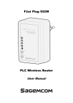
HIGH PERFORMANCE WIRELESS N300 VPN
ROUTER
User Manual
F9K1004v1 8820-01044 Rev. A00
Table Of COnTenTs
Introduction… . . . . . . . . . . . . . . . . . . . . . . . . . . . . . . . . . . . . . . . . . . . . .1
system . . . . . . . . . . . . . . . . . . . . . . . . . . . . . . . . . . . . . . . . . . . . . . . . . 27
Package Contents . . . . . . . . . . . . . . . . . . . . . . . . . . . . . . . . . . . . . . . . . . . .
System Requirements . . . . . . . . . . . . . . . . . . . . . . . . . . . . . . . . . . . . . . . . .
Introduction. . . . . . . . . . . . . . . . . . . . . . . . . . . . . . . . . . . . . . . . . . . . . . . . . .
LED Overview. . . . . . . . . . . . . . . . . . . . . . . . . . . . . . . . . . . . . . . . . . . . . . . .
Status . . . . . . . . . . . . . . . . . . . . . . . . . . . . . . . . . . . . . . . . . . . . . . . . . . . . . 27
LAN . . . . . . . . . . . . . . . . . . . . . . . . . . . . . . . . . . . . . . . . . . . . . . . . . . . . . . . 31
DHCP. . . . . . . . . . . . . . . . . . . . . . . . . . . . . . . . . . . . . . . . . . . . . . . . . . . . . . 35
Schedule . . . . . . . . . . . . . . . . . . . . . . . . . . . . . . . . . . . . . . . . . . . . . . . . . . . 38
Log . . . . . . . . . . . . . . . . . . . . . . . . . . . . . . . . . . . . . . . . . . . . . . . . . . . . . . . . 40
Language . . . . . . . . . . . . . . . . . . . . . . . . . . . . . . . . . . . . . . . . . . . . . . . . . . 41
1
1
2
3
before you begin . . . . . . . . . . . . . . . . . . . . . . . . . . . . . . . . . . . . . . . . . .4
Considerations for Wireless Installation . . . . . . . . . . . . . . . . . . . . . . . . . . 4
Computer Settings (Windows XP/Windows Vista/Windows 7) . . . . . . . 5
Hardware Installation. . . . . . . . . . . . . . . . . . . . . . . . . . . . . . . . . . . . . . . . . 10
Configuring your Router . . . . . . . . . . . . . . . . . . . . . . . . . . . . . . . . . . .11
Internet . . . . . . . . . . . . . . . . . . . . . . . . . . . . . . . . . . . . . . . . . . . . . . . . . 42
Status . . . . . . . . . . . . . . . . . . . . . . . . . . . . . . . . . . . . . . . . . . . . . . . . . . . . . 42
Dynamic IP Address . . . . . . . . . . . . . . . . . . . . . . . . . . . . . . . . . . . . . . . . . 43
Static IP Address . . . . . . . . . . . . . . . . . . . . . . . . . . . . . . . . . . . . . . . . . . . . 44
PPP over Ethernet (PPPOE). . . . . . . . . . . . . . . . . . . . . . . . . . . . . . . . . . . 45
Point-to-Point Tunneling Protocol (PPTP). . . . . . . . . . . . . . . . . . . . . . . . 47
Layer-2 Tunneling Protocol (L2TP) . . . . . . . . . . . . . . . . . . . . . . . . . . . . . 49
setup Wizard . . . . . . . . . . . . . . . . . . . . . . . . . . . . . . . . . . . . . . . . . . . . .12
Wireless . . . . . . . . . . . . . . . . . . . . . . . . . . . . . . . . . . . . . . . . . . . . . . . . 51
VPn Wizard . . . . . . . . . . . . . . . . . . . . . . . . . . . . . . . . . . . . . . . . . . . . . 26
Basic . . . . . . . . . . . . . . . . . . . . . . . . . . . . . . . . . . . . . . . . . . . . . . . . . . . . . . 51
Advanced . . . . . . . . . . . . . . . . . . . . . . . . . . . . . . . . . . . . . . . . . . . . . . . . . . 54
Security . . . . . . . . . . . . . . . . . . . . . . . . . . . . . . . . . . . . . . . . . . . . . . . . . . . . 56
Filter. . . . . . . . . . . . . . . . . . . . . . . . . . . . . . . . . . . . . . . . . . . . . . . . . . . . . . . 62
Wi-Fi Protected Setup (WPS). . . . . . . . . . . . . . . . . . . . . . . . . . . . . . . . . . 64
Client List . . . . . . . . . . . . . . . . . . . . . . . . . . . . . . . . . . . . . . . . . . . . . . . . . . 67
Policy . . . . . . . . . . . . . . . . . . . . . . . . . . . . . . . . . . . . . . . . . . . . . . . . . . . . . . 68
Table Of COnTenTs
firewall . . . . . . . . . . . . . . . . . . . . . . . . . . . . . . . . . . . . . . . . . . . . . . . . 69
VPn . . . . . . . . . . . . . . . . . . . . . . . . . . . . . . . . . . . . . . . . . . . . . . . . . . . . 85
Enable . . . . . . . . . . . . . . . . . . . . . . . . . . . . . . . . . . . . . . . . . . . . . . . . . . . . . 69
Advanced . . . . . . . . . . . . . . . . . . . . . . . . . . . . . . . . . . . . . . . . . . . . . . . . . . 69
DMZ . . . . . . . . . . . . . . . . . . . . . . . . . . . . . . . . . . . . . . . . . . . . . . . . . . . . . . . 70
Denial of Service (DoS). . . . . . . . . . . . . . . . . . . . . . . . . . . . . . . . . . . . . . . 70
MAC Filter . . . . . . . . . . . . . . . . . . . . . . . . . . . . . . . . . . . . . . . . . . . . . . . . . . 71
IP Filter . . . . . . . . . . . . . . . . . . . . . . . . . . . . . . . . . . . . . . . . . . . . . . . . . . . . 72
URL Filter . . . . . . . . . . . . . . . . . . . . . . . . . . . . . . . . . . . . . . . . . . . . . . . . . . 73
Status . . . . . . . . . . . . . . . . . . . . . . . . . . . . . . . . . . . . . . . . . . . . . . . . . . . . . 86
Profile Setting . . . . . . . . . . . . . . . . . . . . . . . . . . . . . . . . . . . . . . . . . . . . . . . 87
IPSec . . . . . . . . . . . . . . . . . . . . . . . . . . . . . . . . . . . . . . . . . . . . . . . . . . . . 88
L2TP over IPSec . . . . . . . . . . . . . . . . . . . . . . . . . . . . . . . . . . . . . . . . . . . 94
L2TP. . . . . . . . . . . . . . . . . . . . . . . . . . . . . . . . . . . . . . . . . . . . . . . . . . . . . 95
User Setting . . . . . . . . . . . . . . . . . . . . . . . . . . . . . . . . . . . . . . . . . . . . . . . . 98
Wizard . . . . . . . . . . . . . . . . . . . . . . . . . . . . . . . . . . . . . . . . . . . . . . . . . . . . . 99
advanced . . . . . . . . . . . . . . . . . . . . . . . . . . . . . . . . . . . . . . . . . . . . . . . 74
Tools . . . . . . . . . . . . . . . . . . . . . . . . . . . . . . . . . . . . . . . . . . . . . . . . . . 118
Network Address Translation (NAT) . . . . . . . . . . . . . . . . . . . . . . . . . . . . 74
Port Mapping . . . . . . . . . . . . . . . . . . . . . . . . . . . . . . . . . . . . . . . . . . . . . . . 75
Port Forwarding . . . . . . . . . . . . . . . . . . . . . . . . . . . . . . . . . . . . . . . . . . . . . 76
Port Trigger . . . . . . . . . . . . . . . . . . . . . . . . . . . . . . . . . . . . . . . . . . . . . . . . . 77
Application Layer Gateway (ALG) . . . . . . . . . . . . . . . . . . . . . . . . . . . . . . 78
Universal Plug and Play (UPnP). . . . . . . . . . . . . . . . . . . . . . . . . . . . . . . . 79
Quality of Service (QoS) . . . . . . . . . . . . . . . . . . . . . . . . . . . . . . . . . . . . . . 80
Routing . . . . . . . . . . . . . . . . . . . . . . . . . . . . . . . . . . . . . . . . . . . . . . . . . . . . 83
Admin . . . . . . . . . . . . . . . . . . . . . . . . . . . . . . . . . . . . . . . . . . . . . . . . . . . . 118
Time. . . . . . . . . . . . . . . . . . . . . . . . . . . . . . . . . . . . . . . . . . . . . . . . . . . . . . 119
Dynamic DNS (DDNS) . . . . . . . . . . . . . . . . . . . . . . . . . . . . . . . . . . . . . . 120
Power. . . . . . . . . . . . . . . . . . . . . . . . . . . . . . . . . . . . . . . . . . . . . . . . . . . . . 122
Diagnosis . . . . . . . . . . . . . . . . . . . . . . . . . . . . . . . . . . . . . . . . . . . . . . . . . 123
Firmware . . . . . . . . . . . . . . . . . . . . . . . . . . . . . . . . . . . . . . . . . . . . . . . . . . 124
Back-up . . . . . . . . . . . . . . . . . . . . . . . . . . . . . . . . . . . . . . . . . . . . . . . . . . . 125
Reset . . . . . . . . . . . . . . . . . . . . . . . . . . . . . . . . . . . . . . . . . . . . . . . . . . . . . 126
Technical support, Warranty, fCC statement . . . . . . . . . . . . . . 127
InTRODUCTIOn
Package Contents
system Requirements
•BelkinWirelessN300VPNRouter
•RJ-45EthernetBasedInternet(ADSLorCableModem)
•PowerAdapter
•ComputerwithWirelessNetworkfunction
•RJ-45EthernetLANCable
•Windows,MacOSorLinuxbasedoperatingsystems
•CD-ROMwithUserManualandSetupWizard
•InternetExplorerorFirefoxorSafariWeb-BrowserSoftware
•QuickGuide
1
InTRODUCTIOn
Introduction
F9K1004isaWireless11NGigabitVPNRouterwith2
attachableantennasthatdeliversupto6xfasterspeedsand
3xextendedcoveragethan802.11gdevices.F9K1004supports
variousnetworkwithsuperiorthroughputandperformanceand
unparalleledwirelessrange.WithitsWPSfunction,ithelpsusers
toconnecttheirwirelessdeviceswithjustapushofabutton.
There’salsoabuilt-in4-portfull-duplex10/100/1000Fast
SwitchtoconnectyourwiredEthernetdevicestogether.The
Routerfunctiontiesitalltogetherandletsyourwholenetwork
shareahigh-speedcableorDSLInternetconnection.
2
InTRODUCTIOn
leD lights
Icon
Description
Color –Blu e
Wireless lan
Ligh tswhe nWirel es ssignal is activated .
Blinks when Wireless data transfer and blinks when WPS handshake is initialized.
WAN
Internet
Color –Blu e
Steady light-up when ethernet port is plugged in.
Blinks when data transfer.
L AN
lan
Color –Blu e
Ligh tswhe nwired ne t workdeviceis conne cted toRJ - 45po r t.
Blinkswhendatatransferocc ur sonRJ - 4 5por t.
Color –Oran ge
Ligh tswhe ndeviceis po wered ON.
Power
Blink sdeviceis Res et.
3
befORe YOU beGIn
before you begin
Considerations for Wireless Installation
This section will guide you through the installation process.
Placement of the F9K1004 is very important to avoid poor
signal reception and performance. Avoid placing the device
in enclosed spaces such as a closet or cabinet..
The operating distance of all wireless devices cannot be predetermined due to a number of unknown obstacles in the
environment that the device is placed. These could be the
number, thickness and location of walls, ceilings or other objects
that the wireless signals must pass through. Here are some key
guidelines to ensure that you have the optimal wireless range.
1. Keep the number of walls and ceilings between the Belkin
access point and other network devices to a minimum.
Each wall or ceiling can reduce the signal strength; the
degradation depends on the building’s material.
2. Building materials makes a difference. A solid metal door or
aluminum stubs may have a significant negative effect on
range. Position your wireless devices carefully so the signal
can pass through drywall or open doorways. Materials such
as glass, steel, metal, concrete, water (fish tanks), mirrors, file
cabinets and brick will also degrade your wireless signal.
3. Interference can also come from other electrical devices
or appliances that generate RF noise. The most
common types are microwaves or cordless phones.
4
befORe YOU beGIn
Computer settings (Windows XP/Windows Vista/Windows 7)
Windows XP
Windows Vista
•ClickStartbuttonandopenControlPanel.
5
Windows 7
befORe YOU beGIn
•WindowsXP,click[NetworkConnection]
•W indowsVista,click[ViewNetworkStatusandTasks]then[ManageNetworkConnections]
•Windows7,click[ViewNetworkStatusandTasks]then[Changeadaptersettings]
6
befORe YOU beGIn
•Rightclickon[LocalAreaConnection]andselect[Properties].
7
befORe YOU beGIn
•S elect“InternetProtocol(TCP/IP)”andclick[Properties]
•C heck“ClientforMicrosoftNetworks”,“FileandPrinter
SharingforMicrosoftNetworks”,and“InternetProtocol
(TCP/IP)isticked.Ifnot,pleaseinstallthem.
8
befORe YOU beGIn
•S elect“ObtainanIPAddressautomatically”and“Obtain
DNSserveraddressautomatically”thenclick[OK].
9
befORe YOU beGIn
Hardware Installation
This diagram depicts the hardware configuration:
1. Place the unit in an appropriate location
after conducting a site survey.
2.PlugoneendoftheEthernetcableintotheLANportof
thedeviceandanotherendintoyourPC/Notebook.
3.PlugoneendofanotherEthernetcabletoWANportofthe
deviceandtheotherendintoyoucable/DSLmodem(Internet)
4. InserttheDC-inletofthepoweradapterintotheportlabeled
“DC-IN”andtheotherendintothepoweroutletonthewall.
10
COnfIGURInG YOUR ROUTeR
This section will show you how to configure the device
using the web-based configuration interface.
Please use your wireless network adapter to
connect the WIRELESS ROUTER.
Default settings
IP Address
192.168.2.1
Username / Password
admin / admin
Wireless Mode
Enable
Wireless SSID
belkin.xxx
Wireless Security
None
Note: xxx represented in the wireless SSID above is the last 3
characters (lowercase) of your device WLAN MAC Address. This
can be found on the device ID label and is unique for each device.
11
seTUP WIzaRD
1. Open a web browser (Internet Explorer/Firefox/Safari)
and enter the IP Address http://192.168.2.1
2. The default username and password are admin. Once you
have entered the correct username and password, click the
OK button to open the web-base configuration page.
note: If you have changed the default LAN IP Address of the
WIRELESS ROUTER, ensure you enter the correct IP Address.
12
seTUP WIzaRD
3. You will see this webpage if login is successful.
4. Click Wizard to enter the Setup Wizard.
Then click next to begin the wizard.
13
seTUP WIzaRD
5. Select the Operation Mode.
Please ensure you have the proper cables connected
as described in the Hardware Installation section.
14
seTUP WIzaRD
aP Router Mode
a. The device will search for the correct Internet settings automatically.
b. The most appropriate WAN type will be determined and
selected automatically. If it is incorrect, please select
Others to set up the WAN settings manually.
15
seTUP WIzaRD
c. There are many WAN service types available. Please obtain
the correct settings from your Internet Service Provider (ISP).
16
seTUP WIzaRD
static IP address
If your ISP Provider has assigned you a fixed IP address, enter the
assigned IP address, Subnet mask, Default Gateway IP address, and
Primary DNS and Secondary DNS (if available) of your ISP provider.
17
seTUP WIzaRD
Dynamic IP address
The IP Address is allocated automatically. However some
ISP’s will also recognize the MAC address and will reject
connections if the MAC address does not match.
If your ISP has recorded the MAC address of your computer’s
Ethernet LAN card, please connect only the computer with the
authorized MAC address, and click the Clone MaC address button.
This will replace the AP Router MAC address to the
computer MAC address. The correct MAC address
is used to initiate the connection to the ISP.
Dynamic IP Address
18
Hostname
This is optional. Only required if specified by ISP
MaC
The MAC Address that is used to connect to the ISP.
seTUP WIzaRD
PPP over ethernet
ISP requires an account username and password.
PPP over ethernet
19
Username
Username assigned to you by the ISP
Password
Password for this username.
Service
You can assign a name for this service. (Optional)
MTU
The maximum size of packets.
Do not change unless mentioned by the ISP.
seTUP WIzaRD
Point-to-Point Tunneling Protocol (PPTP)
PPTP is used by some ISPs.
20
seTUP WIzaRD
PPTP Wan Interface settings
Wan Interface Type
Select whether the ISP is set to Static IP or Dynamic IP address.
Hostname
This is optional. Only required if specified by ISP
MaC address
The MAC address that is used to connect to the ISP.
PPTP settings
login
Username assigned to you by the ISP
Password
Password for this username.
service IP address
The IP Address of the PPTP server.
Connection ID
This is optional. Only required if specified by ISP
MTU
The maximum size of packets.
Do not change unless mentioned by the ISP.
21
seTUP WIzaRD
layer-2 Tunneling Protocol (l2TP)
L2TP is used by some ISPs.
22
seTUP WIzaRD
l2TP Wan Interface settings
Wan Interface Type
Select whether the ISP is set to Static IP or Dynamic IP address.
Hostname
This is optional. Only required if specified by ISP
MaC address
The MAC address that is used to connect to the ISP.
l2TP settings
login
Username assigned to you by the ISP
Password
Password for this username.
service IP address
The IP Address of the PPTP server.
MTU
The maximum size of packets.
Do not change unless mentioned by the ISP.
23
seTUP WIzaRD
d. Choose the level of wireless security.
Belkin recommends the Highest level of security.
Note: 802.11n wireless speeds may not be achievable
if the security level is setting the Lowest or Low.
SSID
Enter the name of your wireless network.
Key
Enter the security key for your wireless network.
24
seTUP WIzaRD
e. Check the settings are correct, and then
click Reboot to apply the settings.
25
VPn WIzaRD
Using the VPN Wizard, you can establish VPN
connection easily. Please refer to page 99.
26
sYsTeM
status
This page will display the status of the device.
status
Model
Description of this device.
Mode
The mode the device is currently in.
Uptime
The duration of time the device has been operating without powering down or rebooting.
Current Date/Time
The device’s system time.
If this is incorrect, please set the time in the Tools / Time page.
Hardware version and
serial number
Hardware information for this device.
application version
Firmware information for this device.
27
sYsTeM
Wan settings
attain IP Protocol
Method used to connect to the Internet.
IP address
The WAN IP Address of the device.
subnet Mask
The WAN Subnet Mask of the device.
MaC address
The MAC address of the device’s WAN Interface.
Primary and secondary Dns
Primary and Secondary DNS servers assigned to the WAN connection.
28
sYsTeM
lan settings
IP address
The LAN IP Address of the device.
subnet Mask
The LAN Subnet Mask of the device.
DHCP server
Whether the DHCP server is Enabled or Disabled.
MaC address
The MAC address of the device’s LAN Interface.
29
sYsTeM
Wlan settings
Channel
The wireless channel in use.
essID
The SSID (Network Name) of the wireless network.
(up to 4 SSIDs are supported)
security
Wireless encryption is enabled for this SSID.
bssID
The MAC address of this SSID.
associated Clients
The number of wireless clients connected to this SSID.
30
sYsTeM
lan
This page allows you to modify the device’s LAN settings.
31
sYsTeM
lan IP
IP address
The LAN IP Address of this device.
IP subnet Mask
The LAN Subnet Mask of this device.
802.1d spanning Tree
When Enabled, the Spanning Tree protocol will prevent network loops in your LAN network.
32
sYsTeM
DHCP server
DHCP server
The DHCP Server automatically allocates IP addresses to your LAN device.
lease Time
The duration of time that the DHCP server will allocate each IP address to a LAN device.
start / end IP
The range of IP addresses that the DHCP server will allocate to a LAN device.
Domain name
The domain name for this LAN network.
33
sYsTeM
Two DNS servers can be assigned for use by your LAN device.
There are four modes available.
Dns servers
from IsP
The DNS server IP address is assigned from your ISP.
User-Defined
The DNS server IP address is assigned manually.
Dns Relay
LAN clients are assigned the device’s IP address as the DNS server.
34
sYsTeM
DHCP
This page shows the status of the DHCP server and also allows you to control how the IP addresses are allocated.
35
sYsTeM
The DHCP Client Table shows the LAN clients that have
been allocated an IP address from the DHCP Server
DHCP Client Table
IP address
The LAN IP address of the client.
MaC address
The MAC address of the client’s LAN interface.
expiration Time
The time that the allocated IP address will expire.
Refresh
Click this button to update the DHCP Client Table.
36
sYsTeM
You can also manually specify the IP address that will be allocated
to a LAN client by associating the IP address with its MAC address.
Type the IP address you would like to manually
assign to a specific MAC address and click Add to
add the condition to the Static DHCP Table.
37
sYsTeM
schedule
This page allows you to setup the schedule times that the Firewall
and Power Saving features will be activated / deactivated.
Click Add to create a Schedule entry.
38
sYsTeM
schedule
schedule Description
Assign a name to the schedule.
service
The service provides for the schedule.
Days
Define the Days to activate or deactivate the schedule.
Time of day
Define the Time of day to activate or deactivate the schedule.
Please use a 24-hour clock format.
39
sYsTeM
log
This page displays the system log of the device. When
powered down or rebooted, the log will be cleared.
log
save
Save the log to a file.
Clear
Clear the log.
Refresh
Update the log.
40
sYsTeM
language
This page allows you to change the Language of the User Interface.
41
InTeRneT
The Internet section allows you to manually set the
WAN type connection and its related settings.
status
This page shows the current status of the device’s WAN connection.
42
InTeRneT
Dynamic IP address
The IP Address is allocated automatically. However some
ISP’s will also recognize the MAC address and will reject
connections if the MAC address does not match.
If your ISP has recorded the MAC address of your computer’s
Ethernet LAN card, please connect only the computer with the
authorized MAC address, and click the Clone MaC button.
This will replace the AP Router MAC address to the
computer MAC address. The correct MAC address
is used to initiate the connection to the ISP.
Dynamic IP address
Hostname
This is optional. Only required if specified by ISP
MaC address
The MAC Address that is used to connect to the ISP.
Dns servers
Two DNS servers can be assigned for use by your LAN devices.
There are two modes available.
from IsP
LAN devices are assigned the DNS server IP address of your ISP.
User-Defined
Set the DNS server IP address manually.
43
InTeRneT
static IP address
If your ISP Provider has assigned you a fixed IP address, enter the
assigned IP address, Subnet mask, Default Gateway IP address, and
Primary DNS and Secondary DNS (if available) of your ISP provider.
static IP address
IP address
Assign an IP address Manually.
IP subnet Mask
Specify an IP address’s subnet mask.
Default Gateway
Specify the gateway of your network.
Primary Dns
Specify the primary DNS server’s IP address.
secondary Dns
Specify the second DNS server’s IP address.
44
InTeRneT
PPP over ethernet
ISP requires an account username and password
45
InTeRneT
PPP over ethernet (PPPoe)
Username
Username assigned to you by the ISP
Password
Password for this username.
service
You can assign a name for this service. (Optional)
MTU
The maximum size of packets.
Do not change unless mentioned by the ISP.
authentication type
Select whether the ISP uses PAP or CHAP methods for authentication. Select auto if unsure.
You can choose the method that the router maintains the connection with the ISP.
Keep Connection:
Type
Manual Connection:
Idle Timeout:
The device will maintain a constant connection with the ISP.
automatic Connection: The device will only initiate connection to the ISP when there is an
Internet connection request made from a LAN device.
The user will need to manually connect to the ISP by clicking the Connect button.
When the connection type is automatic Connection, and Internet traffic is
idle, then the device will automatically disconnect from the ISP.
Please specify the Idle time in minutes.
46
InTeRneT
Point-to-Point Tunneling Protocol (PPTP)
PPTP is used by some ISPs.
47
InTeRneT
Point-to-Point Tunneling Protocol (PPTP)
Wan Interface Type
Select whether the ISP is set to Static IP or will allocate a Dynamic IP address.
Hostname
This is optional. Only required if specified by ISP.
MaC address
The MAC Address that is used to connect to the ISP.
Username
Username assigned to you by the ISP.
Password
Password for this username.
service IP address
The IP Address of the PPTP server.
Connection ID
This is optional. Only required if specified by ISP.
MTU
The maximum size of packets.
Do not change unless mentioned by the ISP.
Type
Keep Connection:
You can choose the method that the router maintains a connection with the ISP.
The device will maintain a constant connection with the ISP.
automatic Connection: The device will only initiate a connection to the ISP when there is
an Internet connection request made from a LAN device.
Manual Connection:
Idle Timeout:
The user will need to manually connect to the ISP by clicking the Connect button.
When the connection type is automatic Connection, when Internet traffic is
idle, then the device will automatically disconnect from the ISP.
Please specify the Idle time in minutes.
48
InTeRneT
layer-2 Tunneling Protocol (l2TP)
L2TP is used by some ISPs..
49
InTeRneT
layer-2 Tunneling Protocol (l2TP)
Wan Interface Type
Select whether the ISP is set to Static IP or will allocate a Dynamic IP address.
Hostname
This is optional. Only required if specified by ISP
MaC address
The MAC Address that is used to connect to the ISP.
Username
Username assigned to you by the ISP
Password
Password for this username.
service IP address
The IP Address of the L2TP server.
MTU
The maximum size of packets.
Do not change unless mentioned by the ISP.
Type
Keep Connection:
You can choose the method that the router maintains a connection with the ISP.
The device will maintain a constant connection with the ISP.
automatic Connection: The device will only initiate a connection to the ISP when there is
an Internet connection request made from a LAN device.
Manual Connection:
Idle Timeout:
The user will need to manually connect to the ISP by clicking the Connect button.
When the connection type is automatic Connection, and when Internet traffic
is idle, then the device will automatically disconnect from the ISP.
Please specify the Idle time in minutes.
50
WIReless
The Wireless section allows you to configure the Wireless settings.
basic
This page shows the current status of the device’s Wireless settings.
51
WIReless
basic
Radio
Enable or Disable the device’s wireless signal.
Mode
Select between Access Point or Wireless Distribution System (WDS) modes.
Select the types of wireless clients that the device will accept.
band
e.g.: 2.4 GHz (b+G+n)
Only 802.11b and 11g clients will be allowed.
enable ssID#
Select the number of SSID’s (Wireless Network names) you would like.
You can create up to 4 separate wireless networks.
ssID#
Enter the name of your wireless network. You can use up to 32 characters.
auto Channel
When enabled, the device will scan the wireless signals around your
area and select the channel with the least interference.
Channel
Manually select which channel the wireless signal will use.
Check Channel Time
When Auto Channel is Enabled, you can specify the period that the
device will scan the wireless signals around your area.
52
WIReless
Wireless Distribution system (WDs)
Use WDS to connect Access Point wirelessly. Doing
so extends a wired infrastructure to locations where
cabling is not possible or inefficient to implement.
Note that compatibility between different brands and models is
not guaranteed. It is recommended that the WDS network be
created using the same models for maximum compatibility.
Also note that all Access Points in the WDS network needs
to use the same Channel and Security settings.
To create a WDS network, please enter the MAC addresses
of the Access Points that you want included in the WDS.
There can be a maximum of four access points.
53
WIReless
advanced
This page allows you to configure wireless advance
settings. It is recommended the default settings are used
unless the user has experience with these functions.
54
WIReless
advanced
fragment Threshold
Specifies the size of the packet per fragment. This function can reduce the chance of packet collision.
However when this value is set too low, there will be increased overheads resulting in poor performance.
RTs Threshold
When the packet size is smaller than the RTS Threshold, then the packet will be sent
without an RTS/CTS handshake which may result in an incorrect transmission.
beacon Interval
The time interval that the device broadcasts a beacon. This beacon is
used to synchronize all wireless clients on the network.
DTIM Period
A Delivery Traffic Indication Message informs all wireless clients that
the access point will be sending Multi-casted data.
n Data Rate
You can limit the transfer rates between the device and wireless clients. Each
Modulation Coding Scheme (MCS) refers to a specific transfer speed.
Channel bandwidth
Set whether each channel uses 20 or 40Mhz.
To achieve 11n speeds, 40Mhz channels must be used.
A preamble is a message that helps access points synchronize with the client.
Preamble Type
A Long Preamble is standard based so it increases compatibility.
A Short Preamble is non-standard, so it decreases compatibility but increases performance.
CTs Protection
When Enabled, the performance is slightly lower however the chances of packet collision is greatly reduced.
Tx Power
Set the power output of the wireless signal.
55
WIReless
security
This page allows you to set the wireless security settings.
56
WIReless
security
ssID selection
Select the SSID that the security settings will apply to.
broadcast ssID
If Disabled, the device will not broadcast the SSID. It will be invisible to wireless clients.
WMM
Wi-Fi Multi-Media is a Quality of Service protocol which prioritizes traffic in
the order according to voice, video, best effort, and background.
Note that in certain situations, WMM needs to be enabled to achieve 11n transfer speeds.
encryption
The encryption method to be applied.
You can choose from WEP, WPA pre-shared key or WPA RADIUS.
• Disabled - no data encryption is used.
• WeP - data is encrypted using the WEP standard.
• WPa-PsK - data is encrypted using the WPA-PSK standard. This is a later standard than WEP, and
provides much better security than WEP. If all your Wireless stations support WPA-PSK, you should use
WPA-PSK rather than WEP.
• W Pa2-PsK - This is a further development of WPA-PSK, and offers even greater security, using the AES
(Advanced Encryption Standard) method of encryption.
• WPa-RaDIUs - This version of WPA requires a Radius Server on your LAN to provide the client
authentication according to the 802.1x standard. Data transmissions are encrypted using the
WPA standard.
If this option is selected:
• ThisAccessPointmusthavea“clientlogin”ontheRadiusServer.
• Eachusermusthavea“userlogin”ontheRadiusServer.
• Eachuser’swirelessclientmustsupport802.1xandprovidethelogindatawhenrequired.
• A
lldatatransmissionsareencryptedusingtheWPAstandard.Keysareautomaticallygenerated,sono
key input is required
57
WIReless
IEEE 802.1x is an authentication protocol. Every user must use
a valid account to login to this Access Point before accessing
the wireless LAN. The authentication is processed by a RADIUS
server. This mode only authenticates users by IEEE 802.1x,
but it does not encrypt the data during communication.
802.1x authentication
RaDIUs server IP address
The IP Address of the RADIUS Server
RaDIUs server port
The port number of the RADIUS Server.
RaDIUs server password
The RADIUS Server’s password.
58
WIReless
WeP encryption:
WeP encryption
authentication Type
Please ensure that your wireless clients use the same authentication type.
Key type
asCII: regular text (recommended)
HeX: for advanced users
Key length
Select the desired option, and ensure the wireless clients use the same setting.
• 64 Bit - data is encrypted, using the default key, before being transmitted. You must enter at
least the default key. For 64 Bit Encryption, the key size is 10 chars in HEX (0~9 and A~F).
•128 bit - data is encrypted, using the default key, before being transmitted. You must enter at
least the default key. For 128 Bit Encryption, the key size is 26 chars in HEX (0~9 and A~F).
Default Key
Select the key you wish to be the default. Transmitted data is ALWAYS encrypted
using the Default Key; the other Keys are for decryption only.
You must enter a Key Value for the Default Key.
encryption Key #
Enter the key value or values you wish to use. Only the Key selected
as Default is required. The others are optional.
59
WIReless
WPa RaDIUs encryption:
WPa RaDIUs encryption
WPa type
Select the WPA encryption you would like.
Please ensure that your wireless clients use the same settings.
RaDIUs server IP address
Enter the IP address of the RADIUS Server.
RaDIUs server Port
enter the port number used for connections to the RaDIUs server.
RaDIUs server password
Enter the password required to connect to the RADIUS server.
60
WIReless
WPa Pre-shared Key encryption:
WPa Pre-shared Key encryption
authentication Type
WPa type
Pre-shared Key Type
Pre-shared Key
Please ensure that your wireless clients use the same authentication type.
Select the WPA encryption you would like.
Please ensure that your wireless clients use the same settings.
Select whether you would like to enter the Key in HEX or Passphrase format.
Wireless clients must use the same key to associate the device.
If using passphrase format, the Key must be from 8 to 63 characters in length.
61
WIReless
filter
This page allows you to create filters to control which
wireless clients can connect to this device by only allowing
the MAC addresses entered into the Filtering Table.
62
WIReless
Wireless filter
enable Wireless
access Control
Check the box to Enable Wireless Access Control.
Description
Enter a name or description for this entry.
MaC address
Enter the MAC address of the wireless client that you wish to allow a connection.
add
Click this button to add the entry.
Reset
Click this button if you have made a mistake and want to reset the MAC address and Description fields.
When Enabled, only wireless clients on the Filtering Table will be allowed.
MaC address filtering Table
Only clients listed in this table will be allowed access to the wireless network.
Delete selected
Delete the selected entries.
Delete all
Delete all entries.
Reset
Un-check all selected entries.
63
WIReless
Wi-fi Protected setup (WPs)
WPS feature is follows the Wi-Fi Alliance WPS standard
and it eases the setup of security-enabled Wi-Fi networks
in the home and small office environment.
It reduces the user steps required to configure a network and
supports two methods that are familiar to most consumers
for configuring a network and enabling security.
64
WIReless
Wi-fi Protected setup (WPs)
WPs
Check to Enable the WPS feature.
WPs button
Check to Enable the WPS push button.
Wi-fi Protected setup Information
Shows whether the WPS function is Configured or Un-configured.
WPs Current status
Configured means that WPS has been used to authorize a connection
between the device and wireless clients.
ssID
The SSID (wireless network name) used when connecting using WPS.
authentication Mode
Shows the encryption method used by the WPS process.
Passphrase Key
This is the passphrase key that is randomly generated during the WPS process. It is required
if wireless clients that do not support WPS attempt to connect to the wireless network.
WPs Via Push button
Click this button to initialize the WPS feature using the push button method.
WPs Via PIn
Enter the PIN code of the wireless device and click this button to
initialize the WPS feature using the PIN method.
65
WIReless
Initializing WPs feature
There are two methods to initialize the WPS feature: Push Button and Pin Code methods.
1. WPs Push button Method
2. Pin Code Method
Push the WPS button on the F9K1004, the Wireless LED
light will start to flash when WPS process is ready.
Note the Pin code of your WIRELESS ROUTER device.
While the Wireless LED is flashing on the F9K1004, press the
WPS button on your wireless client. This could either be a
physical hardware button, or a software button in the utility.
Please use this Pin code to initiate the WPS process
from the wireless client configuration utility.
This process will be different for each brand or model. Please
consult the user manual of the wireless client for more information.
66
WIReless
Client list
This page shows the wireless clients that are
connected to the WIRELESS ROUTER device.
67
WIReless
Policy
This page allows you to configure the access
policies for each SSID (wireless network).
Policy
Wan Connection
Allow wireless clients on this SSID to access the WAN port which typically is an Internet connection.
Communication between
Wireless clients
Dictates whether or not each wireless client can communicate with each other in this
SSID. When Disabled, the wireless clients will be isolated from each other.
Communication between
Wireless clients and
Wired clients
Dictates whether or not wireless clients on this SSID can communicate
with computers attached to the wired LAN port.
68
fIReWall
The Firewall section allows you to set the access control and Firewall settings.
enable
advanced
This page allows you to Enable / Disable the Firewall features.
If Enabled Firewall service, the Denial of Service (DoS) and SPI
(Stateful Packet Inspection) features will also be enabled.
You can choose whether to allow VPN (Virtual Private
Network) packets to pass through the Firewall.
69
fIReWall
DMz
Denial of service (Dos)
If enabled this feature, allows the DMZ computer on your LAN to be
exposed to all users on the Internet.
Denial of Service (Denial of Service) is a type of Internet
attack that sends a high amount of data to you with
the intent to overload your Internet connection.
Enable the DoS firewall feature to automatically
detect and block these DoS attacks.
• Thisallowsalmostanyapplicationtobeusedontheserver.
• The“DMZPC”willreceiveallUnknownconnectionsanddata.
• I ftheDMZfeatureisenabled,pleaseentertheIPaddressof
thePCtobeusedasthe“DMZPC”
note: The“DMZPC”iseffectivelyoutsidetheFirewall,makingitmore
vulnerable to attacks. For this reason, you should only enable the
DMZ feature when required.
70
fIReWall
MaC filter
You can choose whether to Deny or Allow those computers listed in
theMACFilteringtableaccesstotheInternet.
MaC filter
enable MaC filtering
CheckthisboxtoEnabletheMACfilteringfeature.
Deny all clients with MaC addresses
listed below to access the network
Whenselected,thecomputerslistedintheMACFilteringtablewillbeDeniedaccesstotheInternet.
allow all clients with MaC addresses Whenselected,onlythecomputerslistedintheMACFiltering
listed below to access the network
table will be Allowed access to the Internet.
71
fIReWall
IP filter
You can choose whether to Deny or Allow computers with IP
Addresses listed from accessing certain Ports.
This can be used to control which Internet applications the computers
can access.
You may need to have knowledge of what Internet ports the
applications use.
IP filter
enable IP filtering
CheckthisboxtoEnabletheIPfilteringfeature.
Deny all clients with IP addresses
listed below to access the network
When selected, the computers with IP addresses specified will
be Denied access to the indicated Internet ports.
allow all clients with IP addresses
listed below to access the network
When selected, the computers with IP addresses specified will be
Allowed access only to the indicated Internet ports.
72
fIReWall
URl filter
You can deny access to certain websites by blocking keywords in the
URLwebaddress.
Forexample,“gamer”hasbeenaddedtotheURLBlockingTable.Any
webaddressthatincludes“gamer”willbeblocked.
73
aDVanCeD
The Advanced section allows you to configure
the Advanced settings of the router.
network address Translation (naT)
This page allows you to Enable / Disable the Network Address
Translation (NAT) and Network Turbine features. NAT is required
to share one Internet account with multiple LAN users. Enabling
Network Turbine will speed up your NAT throughput. It is required for
certain Firewall features to work properly, but may cause software
compatibility issues. Please disable the feature if it creates issues.
74
aDVanCeD
Port Mapping
Port Mapping allows you to redirect a particular range
of ports to a computer on your LAN network. This helps
you host servers behind the NAT and Firewall.
Port Mapping
enable Port Mapping
Check this box to Enable the Port Mapping feature.
Description
Enter a name or description to help you identify this entry.
local IP
The local IP address of the computer the server is hosted on.
Protocol
Select to apply the feature to either TCP, UDP or Both types of packet transmissions.
Port range
The range of ports that this feature will be applied to.
75
aDVanCeD
Port forwarding
Port Forwarding allows you to redirect a particular public
port to a computer on your LAN network. This helps
you host servers behind the NAT and Firewall.
In the example below, there is a WEB Server running on port 80
on the LAN. For security reasons, the Administrator would like
to provide this server to Internet connection on port 1000.
There is a connection from the Internet on port 1000
and it will be forwarded to the computer with the IP
address 192.168.2.100 and changed to port 80.
Port forwarding
enable Port forwarding
Check this box to Enable the Port Forwarding feature.
Description
Enter a name or description to help you identify this entry.
local IP
The local IP address of the computer the server is hosted on.
Protocol
Select to apply the feature to either TCP, UDP or Both types of packet transmissions.
local Port
The port that the server is running on the local computer.
Public Port
When a connection from the Internet is on this port, then it will be forwarded to the indicated local IP address.
76
aDVanCeD
Port Trigger
If you use Internet applications which use non-standard connections
or port numbers, you may find that they do not function correctly
because they are blocked by the Wireless Router’s firewall. A
Port Trigger will be required for these applications to work.
Port Trigger
enable Port forwarding
Check this box to Enable the Port Trigger feature.
Popular applications
This is a list of some common applications with preset settings.
Select the application and click add to automatically enter the settings.
Trigger port
This is the outgoing (outbound) port numbers for this application.
Trigger type
Select whether the application uses TCP, UDP or Both types of protocols for outbound transmissions.
Public Port
These are the inbound (incoming) ports for this application.
Public type
Select whether the application uses TCP, UDP or Both types of protocols for inbound transmissions.
77
aDVanCeD
application layer Gateway (alG)
Certain applications may require the use of the ALG feature
to function correctly. If you use any of the applications
listed, please check and select it to enable this feature.
78
aDVanCeD
Universal Plug and Play (UPnP)
The UPnP function allows automatic discovery and
configuration of UPnP enabled devices on your network.
It also provides automatic port forwarding for supported
applications to seamlessly bypass the Firewall.
Universal Plug and Play (UPnP)
enable the UPnP feature
Check this box to Enable the UPnP feature to allow supported devices to be visible on the network.
allow users to make
port forwarding changes
through UPnP
Check this box to allow applications to automatically set their port forwarding
rules to bypass the firewall without any user set up.
79
aDVanCeD
Quality of service (Qos)
QoS refers to the capability of a network to provide better service
to selected network traffic. This is to ensure that applications get
enough Internet bandwidth for a pleasant user experience.
If not, then the performance and user experience of time sensitive
transmissions such as voice and video could be very poor.
In order for this feature to function properly, the user
should first set the Uplink and Downlink bandwidth
provided by your Internet Service Provider.
Total bandwidth settings
Uplink
Set the Uplink bandwidth provided by your Internet Service Provider.
Downlink
Set the Downlink bandwidth provided by your Internet Service Provider.
Priority Queue
Sets the QoS method to Priority Queue.
bandwidth allocation
Sets the QoS method to Bandwidth Allocation.
Disabled
Disable the QoS feature.
80
aDVanCeD
Priority Queue Method
Bandwidth priority is set to either High or Low. The
transmissions in the High queue will be processed first.
Unlimited Priority Queue
local IP address
Traffic to this IP address will not be affected by QoS rules.
High / low Priority Queue
Protocol
The type of network protocol.
High / low Priority
Sets the protocol to High or Low priority.
specific Port
Each protocol uses a specific port range. Please specify the ports used by this protocol.
81
aDVanCeD
bandwidth allocation Method
You can set the maximum amount of bandwidth a certain
protocol will use at one time. Or you can set a minimum amount
of bandwidth that will be guaranteed to a certain protocol.
bandwidth allocation
Type
Set the QoS rules to apply to transmissions that are Downloaded/Uploaded or Both directions.
local IP range
Enter the IP address range of the computers that you would like the QoS rules to apply to.
Protocol
Select from this list of protocols to automatically set the related port numbers.
Port range
Each protocol uses a specific port range. Please specify the ports used by this protocol.
Policy
Choose whether this rule sets a limit on the Maximum amount of bandwidth allocated to
this protocol, or sets a guaranteed Minimum amount of bandwidth for this protocol.
82
aDVanCeD
Routing
If your WIRELESS ROUTER device is connected to a
network with different subnets, then this feature will allow
the different subnets to communicate with each other.
static Routing
enable static Routing
Check this box to Enable the Static Router feature.
Destination lan IP
Enter the IP address of the destination LAN.
subnet Mask
Enter the Subnet Mask of the destination LAN IP address
Default Gateway
Enter the IP address of the Default Gateway for this destination IP and Subnet.
Hops
Specify the maximum number of Hops in the static routing rule.
Interface
Select whether the routing applies to LAN or WAN interfaces.
83
aDVanCeD
Destination
subnet Mask
Gateway
Hop
Interface
192.168.11.0
255.255.255.0
192.168.2.216
1
LAN
192.168.10.0
255.255.255.0
192.168.2.103
1
LAN
For example, if Client3 wants to send an IP data packet to 192.168.10.2 (Client 2), it will use
the above table to determine that it has to go via 192.168.2.103 (Router 2)
If it sends Packets to 192.168.11.11 (Client 1) will go via 192.168.2.216 (Router 1)
84
VPn
A Virtual Private Network (VPN) provides a secure connection
between two or more computers or protected networks over the public
Internet. It provides authentication to ensure that the information is
going to and from the correct parties. It provides security to protect
the information from being viewed or being tampered with en route.
F9K1004 supports IPSec (Site to Site, Remote to Site), L2TP
over IPSec and L2TP methods to establish VPN connections.
The maximum VPN session number is up to 5.
85
VPn
status
This page displays the connect status of VPN connection. You can
select one of them to connect or disconnect the VPN connection.
Note: If connection type is remote dial-in (Client to Site or L2TP
over IPSec), you can’t disconnect this session manually.
86
VPn
Profile setting
This page allows you to enable, add, edit and Delete VPN profiles.
Profile setting
enable
Check the box to Enable the VPN profile.
add
Click this button to add the entry.
edit
Select one profile and click this button to edit the entry.
Delete selected
Delete the selected entries.
Delete all
Delete all entries
87
VPn
IPsec
IPSec (Internet Protocol Security) is a protocol suite for securing
Internet Protocol (IP) communications by authenticating and
encrypting each IP packet of a communication session. IPSec
also includes protocols for establishing mutual authentication
between agents at the beginning of the session and negotiation
of cryptographic keys to be used during the session.
IPSec is an end-to-end security scheme operating in the
Internet Layer of the Internet Protocol Suite. It can be used in
protecting data flows between a pair of hosts (host-to-host),
between a pair of security gateways (network-to-network), or
between a security gateway and a host (network-to-host).
General
The page allows you to configure the general VPN settings.
88
VPn
General
name
Enter a name for your VPN policy.
Connection Type
Supports IPsec, l2TP over IPsec and l2TP methods to establish VPN connection.
authentication Type
Supports pre-shared key method for authentication.
shared Key
Enter the Shared Key in box. (example: 1234567890)
Confirm
Enter your Shared Key again for verification.
local ID Type
Supports IP address, Domain name, email address methods for Local ID Type.
local ID
Enter an ID to identify and authenticate the local VPN endpoint. (WAN IP of the local F9K1004)
Peer ID Type
Supports IP address, Domain name, email address methods for Peer ID Type.
Peer ID
Enter an ID to identify and authenticate the remote VPN endpoint. (WAN IP of
the remote VPN router, only required for Site to Site VPN connection)
89
VPn
sa (security association)
A Security Association (SA) is the establishment of shared
security attributes between two network entities to support
secure communication. An SA may include attributes such as:
cryptographic algorithms and mode; traffic encryption keys;
and parameters for the network data to be passed over the
connection. Establishment of an SA is described in RFC 2408, the
Internet Security Association and Key Management Protocol.
This page allows you to configure SA.
90
VPn
sa (security association)
IKe (Phase 1) Proposal
exchange
Select Main Mode or Aggressive Mode for IKE Phase 1 negotiation.
• Main Mode: Select this option to configure the standard negotiation parameters
for IKE Phase 1 of the VPN Tunnel. (Recommended Setting)
• Aggressive Mode: Select this option to configure IKE Phase 1 of the VPN Tunnel to carry
out negotiation in a shorter amount of time. (Not Recommended - Less Secure)
DH Group
Select a DH Group from the drop-down menu (Group 1, Group2, Group5 and Group14). As the DH
Group number increases, the higher the level of encryption implemented for IKE Phase 1.
encryption
F9K1004 supports Des, 3Des, aes128, aes192, aes256 encryption methods for traffic through the VPN.
authentication
F9K1004 supports SHA1, MD5 methods for authentication.
life Time
Enter the number of seconds for the IKE Lifetime. The period of time to pass before establishing a
new IKE security association (SA) with the remote endpoint. The default value is 28800.
IPsec (Phase 2) Proposal
Protocol
Select ESP (Encapsulating Security Payload) or AH (Authentication Header) for traffic through the VPN.
• AH (Authentication Header) to provide connectionless integrity and data origin
authentication for IP datagrams and to provide protection against replay attacks.
• esP (encapsulating security Payload) to provide confidentiality, data origin authentication, connectionless
integrity, an anti-replay service (a form of partial sequence integrity), and limited traffic flow confidentiality.
encryption
F9K1004 supports Des, 3Des, aes128, aes192, aes256 encryption methods for traffic through the VPN.
authentication
F9K1004 supports SHA1, MD5 methods for authentication.
Perfect forward secrecy
Select Enable or Disable to enable or disable PFS (Perfect Forward Secrecy). PFS is an additional security protocol.
DH Group
Select a PFS DH Group from the drop-down menu (Group 1, Group2, Group5, Group14). As the
DH Group number increases, the higher the level of encryption implemented for PFS.
life Time
Enter the number of seconds for the IPSec Lifetime. The period of time to pass before establishing a
new IPSec security association (SA) with the remote endpoint. The default value is 28800.
91
VPn
network
This page allows you to configure the VPN
server and local/remote subnet.
network
security Gateway Type
Security Gateway Type supports IP address and Domain name. Select one of them.
security Gateway
The IP address or domain name of the VPN server.
local network
Enter the local (LAN) subnet and mask. (ex. 192.168.2.0/255.255.255.0)
Remote network
Enter the remote subnet and mask. (ex. 192.168.9.0/255.255.255.0)
92
VPn
advanced
This page allows you to configure advanced VPN settings.
advanced
naT Traversal
Enabling naT Traversal allows IPSec traffic from this endpoint to traverse through
the translation process during NAT. The remote VPN endpoint must also support
this feature and it must be enabled to function properly over the VPN.
Dead Peer Detection
Enable DPD (Dead Peer Detection) to delete the VPN tunnel if there is no traffic
detected. The VPN will re-establish once traffic is again sent through the tunnel.
93
VPn
l2TP over IPsec
L2TP over IPSec VPNs enable a business to transport data
over the Internet, while still maintaining a high level of security
to protect data. You can use this type of secure connection
for small or remote office clients that need access to the
corporate network. You can also use L2TP over IPSec VPNs
for routers at remote sites by using the local ISP and creating
a demand-dial connection into corporate headquarters.
General
The page allows you to configure the general VPN settings.
General
name
Enter a name for your VPN policy.
Connection Type
F9K1004 Supports IPsec, l2TP over IPsec and l2TP methods to establish VPN connection.
authentication Type
F9K1004 supports pre-shared key method for authentication.
shared Key
Enter the Shared Key in box. (example: 1234567890)
Confirm
Enter your Shared Key again for verification.
94
VPn
network
l2TP
l2TP
network
authentication
Select the desired authentication
protocol (PAP, CHAP, MSCHAP_V2).
Select MSCHAP_V2 by default
server IP
Assign the VPN Server IP address.
(example: 192.168.99.1)
account
Select accounts form available Users to
member for authentication. You should set
these available users in user setting page.
Remote IP Range
Assign a range of IP addresses. The assigned
IP range should be on the same range as the
Server IP (example: 192.168.99.21 – 50)
95
VPn
General
l2TP
L2TP (The Layer 2 Tunnel Protocol) is a tunneling protocol used
to support virtual private networks (VPNs). It does not provide any
encryption or confidentiality by itself; it relies on an encryption
protocol that it passes within the tunnel to provide privacy.
General
96
name
Enter a name for your VPN policy
Connection Type
Supports L2TP methods to
establish VPN connection
VPn
network
l2TP
l2TP
network
authentication
Select the desired authentication
protocol (PAP, CHAP, MSCHAP_V2).
Select MSCHAP_V2 by default
server IP
Assign the VPN Server IP address.
(example: 192.168.99.1)
account
Select accounts form available to member
for authentication. You should set these
available users in user setting page.
Remote IP Range
Assign a range of IP addresses. The assigned
IP range should be on the same range as the
Server IP (example: 192.168.99.21 – 50)
97
VPn
User setting
This page display the available users of VPN connection. You can
add and delete the VPN available users here. You can enter the
user name and password then click Add button to add a user.
You can select users in Current VPN User Table then
click Delete Selected button to delete users.
User setting
98
name
User’s name to be setup
Password
Assign password
Confirm
Re-enter password
add
Create the user account
Reset
Clear the input box
Delete selected
Delete the selected entries.
Delete all
Delete all entries
VPn
Wizard
You can use Wizard to create a VPN profile easily.
1. Click next button to begin the wizard.
2. Enter the VPN policy name then click
the next button to next page.
99
VPn
3. You can select [IPSec] or [L2TP over IPSec] or [L2TP] in this
page then click the next button to go to the next page. If you
select [IPSec] then go to step “a.” If you select [L2TP over IPSec]
then go to step “b.” if you select [L2TP] then go to step “c.”
a. IPsec
You can select [Client to Site] or [Site to Site] in this page
then click the next button to go to the next page.
note. If you select [Client to Site], you will skip Step 4.
100
VPn
Enter the Security Gateway and remote network. Then
click the next button to go to the next page.
b. l2TP over IPsec
Enter the username, password and VPN server IP setting.
Then click the next button to go to the next page.
101
VPn
c. l2TP
Enter the username, password and VPN server IP setting.
Then click the next button to go to the next page.
4. Enter the shared key for the VPN connection
102
VPn
5. Setup successful, enable this policy immediately. If you
don’t want to enable this policy, you can un-check the box.
Then click the apply button to apply the settings.
103
VPn
How to establish an l2TP over IPsec VPn
connection on Windows XP
1. Click the Start button and open Control Panel.
2. Click [Network Connections], double click [New
Connection Wizard] then click the next button.
104
VPn
3. Select [Connect to the network at my
workplace] then click the next button.
4. Select [Virtual Private Network connection]
then click the next button.
105
VPn
5. Enter the [Company Name] then click the next button.
6. Select [Do not dial the initial connection]
then click the next button.
106
VPn
7. Enter the VPN server IP address then click the next button.
8. Select [Do not use my smart card] then click the next button.
107
VPn
9. Click the finish button to complete the wizard.
10. Click the Properities button.
108
VPn
11. In Security, select [Advanced (custom settings)]
then click the settings button.
12. Check [Unencrypted password (PAP)] and [Challenge Handshake
Authentication Protocol (CHAP)] then click the OK button.
109
VPn
13. Click [IPSec Settings] then check [Use pre-shared key for
authentication], Enter the Key then click the OK button.
14. In Networking, select [L2TP IPSec VPN] then click the OK button.
110
VPn
15. Click the Connect button to connect VPN connection.
16. You can see that the VPN Connection has been established
111
VPn
How to establish an l2TP over IPsec
VPn connection in Windows 7
1. Click the Start button and open Control Panel.
2. Click [View Network Status and Tasks] then
[Set up a new connection or network]
112
VPn
3. Click [Connect to a workplace] then [Use
my Internet connection (VPN)]
113
VPn
4. Enter the VPN server IP address: [Internet address],
[Destination name] and check [Don’t connect now; just set
it up so I can connect later], then click the next button.
5. Enter the correct User name and Password
then click the Create button.
114
VPn
7. Click [Change adapter settings] in Step 2, then select VPn
Connection and click [Change settings of this connection]
6. Click the Close button to close the VPN connection settings.
115
VPn
8. Change Type of VPN to [Layer 2 Tunneling Protocol with IPSec
(L2TP/IPSec)] and check [Unencrypted password (PAP)] in Security.
9. Click the advanced settings button and select
[Use preshared key for authentication] and enter
the correct key. Then click the OK button.
116
VPn
10. Double click the VPn Connection then click the Connect button.
11. You can see that the VPN Connection has been established.
117
TOOls
This section allows you to configure certain device system settings.
admin
This page allows you to change the system password
and to configure remote management.
Change Password
Old Password:
Enter the current password.
new Password:
Enter your new password.
Repeat new Password:
Enter your new password again for verification.
Remote Management
Host address:
You can only perform remote management from the specified IP address.
Leave blank to allow any host to perform remote management.
Port:
Enter the port number you want to accept remote management connections.
enable:
Check to Enable the remote management feature.
118
TOOls
Time
This page allows you to set the system time.
Time
Time setup:
Select the method you want to set the time.
Time zone:
Select the time zone for your current location.
nTP Time server:
Enter the address of the Network Time Protocol (NTP) Server to
automatically synchronize with a server on the Internet.
Daylight savings:
Check if daylight savings applies to your area.
119
TOOls
Dynamic Dns (DDns)
This free service is very useful when combined with the Virtual
Server feature. It allows Internet users to connect to your
Virtual Servers using a URL, rather than an IP Address.
This also solves the problem of having a dynamic IP address. With
a dynamic IP address, your IP address may change whenever
you connect, which makes it difficult to connect to you.
120
TOOls
DDns services work as follows:
1. You must register for the service at one of
the listed DDNS Service providers.
2. After registration, use the Service provider’s normal
procedure to obtain your desired Domain name.
3. Enter your DDNS data on the F9K1004’s DDNS
screen, and enable the DDNS feature.
4. The Wireless Router will then automatically ensure
that your current IP Address is recorded at the DDNS
service provider’s Domain Name Server.
5. From the Internet, users will be able to connect
to your Virtual Servers (or DMZ PC) using your
Domain name, as shown on this screen.
Dynamic Dns
Dynamic Dns
Check this box to Enable the DDNS feature.
server address:
Select the list of Dynamic DNS homes you would like to use from this list.
Username / Password:
Enter the Username and Password of your DDNS account.
121
TOOls
Power
This page allows you to Enable or Disable the
wireless LAN power saving features.
122
TOOls
Diagnosis
This page allows you to determine if the WIRELESS
ROUTER device has an active Internet connection.
Diagnosis
address to Ping:
Enter the IP address you would like to Ping.
Ping Result:
Results of the Ping test.
123
TOOls
firmware
The firmware (software) in the F9K1004 can be
upgraded using your Web Browser.
Go to http://www.belkin.com/support/ , to download
available firmware update for the F9K1004.
To perform the firmware Upgrade:
1. Click the Browse button and navigate to
the location of the upgrade file.
2. Select the upgrade file. Its name will appear
in the field next to the Browse Button.
3. Click the Apply button to complete the firmware upgrade.
note: The Wireless Router is unavailable during the upgrade
process, and must restart when the upgrade is completed. Any
connections to or through the Wireless Router will be lost.
124
TOOls
back-up
back-up
Restore to factory default:
Restores the device to its factory default settings.
backup settings:
Save the current configuration settings to a file.
Restore settings:
Restores a previously saved configuration file.
Click browse to select the file. Then Upload to load the settings.
125
TOOls
Reset
In some circumstances it may be required
to force the device to reboot.
126
TeCHnICal sUPPORT, WaRRanTY, fCC sTaTeMenT
Technical support
Us
http://www.belkin.com/support
UK
http://www.belkin.com/uk/support
australia
http://www.belkin.com/au/support
new zealand
http://www.belkin.com/au/support
singapore
1800 622 1130
europe
http://www.belkin.com/uk/support
127
TeCHnICal sUPPORT, WaRRanTY, fCC sTaTeMenT
belkin International, Inc., limited
2-Year Product Warranty
What is not covered by this warranty?
All above warranties are null and void if the Belkin product is
not provided to Belkin for inspection upon Belkin’s request
at the sole expense of the purchaser, or if Belkin determines
that the Belkin product has been improperly installed, altered
in any way, or tampered with. The Belkin Product Warranty
does not protect against acts of God such as flood, lightning,
earthquake, war, vandalism, theft, normal-use wear and tear,
erosion, depletion, obsolescence, abuse, damage due to low
voltage disturbances (i.e. brownouts or sags), non-authorized
program, or system equipment modification or alteration.
What this warranty covers.
Belkin International, Inc. (“Belkin”) warrants to the original
purchaser of this Belkin product that the product shall be free
of defects in design, assembly, material, or workmanship.
What the period of coverage is.
Belkin warrants the Belkin product for two years.
What will we do to correct problems?
Product Warranty.
Belkin will repair or replace, at its option, any defective product
free of charge (except for shipping charges for the product).
Belkin reserves the right to discontinue any of its products without
notice, and disclaims any limited warranty to repair or replace any
such discontinued products. In the event that Belkin is unable to
repair or replace the product (for example, because it has been
discontinued), Belkin will offer either a refund or a credit toward
the purchase of another product from Belkin.com in an amount
equal to the purchase price of the product as evidenced on the
original purchase receipt as discounted by its natural use.
128
TeCHnICal sUPPORT, WaRRanTY, fCC sTaTeMenT
How to get service.
To get service for your Belkin product you
must take the following steps:
Belkin reserves the right to review the damaged Belkin product.
All costs of shipping the Belkin product to Belkin for inspection
shall be borne solely by the purchaser. If Belkin determines,
in its sole discretion, that it is impractical to ship the damaged
equipment to Belkin, Belkin may designate, in its sole discretion,
an equipment repair facility to inspect and estimate the cost to
repair such equipment. The cost, if any, of shipping the equipment
to and from such repair facility and of such estimate shall be
borne solely by the purchaser. Damaged equipment must remain
available for inspection until the claim is finalized. Whenever
claims are settled, Belkin reserves the right to be subrogated
under any existing insurance policies the purchaser may have.
1. Contact Belkin International, Inc., at 12045 E. Waterfront
Drive, Playa Vista, CA 90094, Attn: Customer Service, or
call (800)-223-5546, within 15 days of the Occurrence.
Be prepared to provide the following information:
a. The part number of the Belkin product.
b. Where you purchased the product.
c. When you purchased the product.
d. Copy of original receipt.
2. Your Belkin Customer Service Representative will then
instruct you on how to forward your receipt and Belkin
product and how to proceed with your claim.
129
TeCHnICal sUPPORT, WaRRanTY, fCC sTaTeMenT
How state law relates to the warranty.
THIS WARRANTY CONTAINS THE SOLE WARRANTY OF
BELKIN. THERE ARE NO OTHER WARRANTIES, EXPRESSED
OR, EXCEPT AS REQUIRED BY LAW, IMPLIED, INCLUDING
THE IMPLIED WARRANTY OR CONDITION OF QUALITY,
MERCHANTABILITY OR FITNESS FOR A PARTICULAR
PURPOSE, AND SUCH IMPLIED WARRANTIES, IF ANY, ARE
LIMITED IN DURATION TO THE TERM OF THIS WARRANTY.
Some states do not allow limitations on how long an implied
warranty lasts, so the above limitations may not apply to you.
IN NO EVENT SHALL BELKIN BE LIABLE FOR INCIDENTAL,
SPECIAL, DIRECT, INDIRECT, CONSEQUENTIAL OR
MULTIPLE DAMAGES SUCH AS, BUT NOT LIMITED TO,
LOST BUSINESS OR PROFITS ARISING OUT OF THE
SALE OR USE OF ANY BELKIN PRODUCT, EVEN IF
ADVISED OF THE POSSIBILITY OF SUCH DAMAGES.
This warranty gives you specific legal rights, and you may also have
other rights, which may vary from state to state. Some states do
not allow the exclusion or limitation of incidental, consequential,
or other damages, so the above limitations may not apply to you.
130
TeCHnICal sUPPORT, WaRRanTY, fCC sTaTeMenT
fCC statement
federal Communications Commission notice
This equipment has been tested and found to comply with the
limits for a Class B digital device, pursuant to Part 15 of the FCC
Rules. These limits are designed to provide reasonable protection
against harmful interference in a residential installation.
DeClaRaTIOn Of COnfORMITY WITH fCC RUles
fOR eleCTROMaGneTIC COMPaTIbIlITY
We, Belkin International, Inc., of 12045 E. Waterfront Drive, Playa
Vista, CA 90094, declare under our sole responsibility that the device,
f9K1004v1, complies with Part 15 of the FCC Rules. Operation is
subject to the following two conditions: (1) this device may not cause
harmful interference, and (2) this device must accept any interference
received, including interference that may cause undesired operation.
This equipment generates, uses, and can radiate radio frequency
energy, and if not installed and used in accordance with the
instructions, may cause harmful interference to radio communications.
However, there is no guarantee that interference will not occur
in a particular installation. If this equipment does cause harmful
interference to radio or television reception, which can be determined
by turning the equipment off and on, the user is encouraged to try and
correct the interference by one or more of the following measures:
Caution: exposure to Radio frequency Radiation.
The device shall be used in such a manner that the potential
for human contact normal operation is minimized.
•
•
•
This equipment complies with FCC radiation exposure
limits set forth for an uncontrolled environment. This
equipment should be installed and operated with a minimum
distance of 20cm between the radiator and your body.
•
Reorientorrelocatethereceivingantenna.
Increasethedistancebetweentheequipmentandthereceiver.
C
onnecttheequipmenttoanoutletonacircuitdifferent
from that to which the receiver is connected.
Consultthedealeroranexperiencedradio/TVtechnicianforhelp.
FCC Caution: Any changes or modifications not expressly
approved by the party responsible for compliance could
void the user’s authority to operate this equipment.
This device and its antenna(s) must not be co-located or
operating in conjunction with any other antenna or transmitter.
131
TeCHnICal sUPPORT, WaRRanTY, fCC sTaTeMenT
Canada-Industry Canada (IC)
The wireless radio of this device complies with RSS
139 & RSS 210 Industry Canada. This Class B digital
apparatus complies with Canadian ICES-003.
Operation is subject to the following two conditions: (1)
this device may not cause interference, and (2) this device
must accept any interference, including interference
that may cause undesired operation of the device.
Cet appareil numérique de la classe B conforme
á la norme NMB-003 du Canada.
132
© 2012 Belkin International, Inc. All rights reserved. All trade names are registered
trademarks of respective manufacturers listed. Safari is a trademark of Apple Inc., registered
in the U.S. and other countries. Internet Explorer is either a registered trademark or
trademark of Microsoft Corporation in the United States and/or other countries.