1
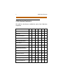
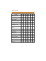
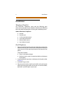
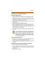
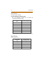
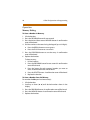
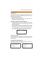
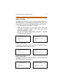
TM STAR P LU S 2700-Ser ies Tel e phones User Guide with Caller ID Features I Issue Release Date Description 1 05-99 Last Revision 2 08-00 Document contains new product information. LIFE SUPPORT APPLICATIONS POLICY VODAVI Technology, Inc. products are not authorized for and should not be used within Life Support applications. Life Support systems are equipment intended to support or sustain life and whose failure to perform when properly used in accordance with instructions provided can be reasonably expected to result in significant personal injury or death. VODAVI Technology, Inc. warranty is limited to replacement of defective components and does not cover injury to persons or property or other consequential damages Copyright © 2000 VODAVI Technology, Inc. All Rights Reserved This material is copyrighted by VODAVI Technology, Inc. Any unauthorized reproductions, use or disclosure of this material, or any part thereof, is strictly prohibited and is a violation of the Copyright Laws of the United States (17 U.S.C. Section 101 et. seq.). VODAVI reserves the right to make changes in specifications at any time and without notice. The information furnished by VODAVI in this material is believed to be accurate and reliable, but is not warranted to be true in all cases. STARPLUS™ is a registered trademark of VODAVI Technology, Inc. seh/2000 PRINTED IN THAILAND Contents Important Safety Instructions .................................................... 1 2700-Series Features ..................................................................... 2 Installation ........................................................................................ 4 Telephone Checklist ............................................................. 4 Desk Telephone ...................................................................... 4 Wall Mounting ........................................................................ 5 A-Lead ........................................................................................ 7 Data Jack ................................................................................... 7 Connecting a Modem to Your Telephone .................... 8 Setting the Volume ............................................................... 8 Ringer Volume Switch..................................................... 8 Speakerphone Volume Switch .................................... 9 Handset Volume ............................................................... 9 B/Z -Type Ringer ............................................................... 9 Directory Card ......................................................................... 9 Operation ........................................................................................ 10 Changing From Handset to Speakerphone ............... 10 Hold (2702, 2703, 2706 models) ..................................... 10 Hold (2704 and 2705 models) ......................................... 11 Message Waiting Indicator ............................................... 11 Flash .......................................................................................... 11 Last Number Redial ............................................................. 12 Mute .......................................................................................... 12 Memory Dialing (2702, 2703, 2704, 2705 models) ... 13 Conferencing (2704/2705 models) ................................ 14 Programming ................................................................................ 15 Tone/Pulse .............................................................................. 15 Flash Timing ........................................................................... 16 Pause Timing ......................................................................... 16 Positive Disconnect ............................................................. 17 S/W Reset ................................................................................ 17 ii August 2000 Caller ID Operation & Programming ..................................... 18 Before You Begin ................................................................. 18 General Caller ID Information .......................................... 19 Caller ID Displays ............................................................ 19 Date and Time Displayed............................................. 19 Things You Should Know …....................................... 19 Operation ................................................................................ 20 Memory Dialing............................................................... 20 Placing a Display Call..................................................... 21 Marking a Call................................................................... 22 Removing Call Records from Call History .............. 22 Caller ID Options .................................................................. 22 Language Select Programming................................. 22 Home Area Code............................................................. 23 Local 1 Area Code........................................................... 23 Local 2 Area Code........................................................... 23 Caller ID with Call Waiting ........................................... 24 Call History ........................................................................ 24 Repeated Calls ................................................................. 25 Visual Message Waiting................................................ 25 Special Ring Alert............................................................ 26 LCD Contrast .................................................................... 26 Programming Functions ................................................... 26 Dial Mode Select ............................................................. 26 Positive Disconnect ....................................................... 27 Flash Time ......................................................................... 27 Pause Time ........................................................................ 27 Software Reset and Memory Initialization............. 27 Troubleshooting Guide ..................................................... 28 Important Safety Instructions 1 Important Safety Instructions When using your telephone equipment, basic safety precautions (including the following) should always be followed to reduce the risk of fire, electric shock, and injury to persons. Read and understand all instructions. Follow all warnings and instructions marked on telephone. Do not use liquid cleaners or aerosol cleaners on the telephone; use a damp cloth for cleaning. Do not operate the telephone near water (i.e., near a bath tub, wash bowl, kitchen sink, laundry tub, in a wet basement, or near a swimming pool). Do not place this telephone on an unstable cart, stand, or table. The telephone may fall causing serious damage to the telephone. Slots and openings on the bottom of the telephone are provided for ventilation to protect it from overheating. These openings must not be blocked or covered. The openings should never be blocked by placing the telephone on the bed, sofa, rug, or other similar surface. This telephone should never be placed near or over a radiator or heat register. This telephone should not be placed in a built-in installation unless proper ventilation is provided. Never push any objects into this telephone through slots as they may touch dangerous voltage points or short-out parts that could result in a fire or electric shock. Never pour any liquids on the telephone. To reduce the risk of electric shock, do not disassemble this telephone. Take the telephone to a qualified serviceman when service or repair work is needed. Opening or removing covers may expose you to dangerous voltage or other risks. Incorrect reassembly can cause electric shock when the appliance is subsequently used. Avoid using a telephone (other than a cordless type) during an electrical storm. There may be a remote risk of electric shock from lightning. Do not use the telephone to report a gas leak in the vicinity of the leak. SAVE THESE INSTRUCTIONS 2 2700-Series Features 2700-Series Features This table lists the features available for each of the 2700-Series Telephones. Feature A-Lead 2701 2703 ▲ ▲ 2705 2702 2704 ▲ 2706 ▲ ▲ Caller ID ▲ Conference Button ▲ Data Jack ▲ ▲ ▲ ▲ ▲ ▲ Desk/Wall Mountable ▲ ▲ ▲ ▲ ▲ ▲ Flash Button ▲ ▲ ▲ ▲ ▲ ▲ Handset Volume ▲ ▲ ▲ ▲ ▲ ▲ ▲ ▲ Hidden Programming Button (hotel/motel only) Hold Button ▲ ▲ ▲ ▲ ▲ Hold for each line ▲ ▲ ▲ ▲ ▲ Line In Use Indicator ▲ ▲ ▲ ▲ ▲ ▲ ▲ ▲ Low/Higher Ringer Low/High/Off Ringer ▲ ▲ ▲ 2700-Series Features Feature 3 2701 2703 2705 2702 2704 2706 ▲ ▲ ▲ ▲ ▲ ▲ Mute Button ▲ ▲ ▲ ▲ ▲ Mute with LED ▲ ▲ ▲ ▲ ▲ 1 1 1 1 100 ▲ ▲ ▲ ▲ ▲ ▲ ▲ ▲ ▲ ▲ Programmable Flexible Buttons 10 10 10 10 12 Programmable Timers ▲ ▲ ▲ ▲ ▲ ▲ ▲ ▲ ▲ ▲ Ring Indicator ▲ ▲ ▲ ▲ ▲ Speakerphone ▲ ▲ ▲ ▲ ▲ Speaker with LED ▲ ▲ ▲ ▲ ▲ Speaker Volume Control ▲ ▲ ▲ ▲ ▲ ▲ ▲ ▲ ▲ ▲ Message Wait Lamp Number Memory (Redial) 1 Pause Positive Disconnect Hookswitch Redial Button Tone/Pulse Two Lines ▲ ▲ ▲ ▲ ▲ 4 Installation Installation Telephone Checklist The 2700-Series Telephones come with the following parts necessary for operation of your telephone. Verify that the following items have been included prior to starting the installation process: Vodavi 2700-Series Telephone Handset Handset cord 12’ line cord (desk mount) 4” line cord (wall mount) Pedestal (desk mount) User Guide (this book) Desk Telephone 1. Plug one end of the handset cord into the handset and plug the other end into the jack on the bottom of the phone. Route and secure the cord in the channel provided on the bottom of the phone. 2706 Caller ID Model: Plug in 9-volt power adapter. Route and secure cord in channel provided on the bottom of the phone. 2. Snap the pedestal into place on the bottom of the phone (refer to Figure 1). 3. Set the B/Z ringer switch. 4. Plug one end of the line cord into the LINE1 jack and plug the other end into the jack outlet on the wall. On two-line models, both LINE1 and LINE2 jacks may be used. Installation 5 Wall Mounting Your telephone is designed for GTE- and AT&T-type RJ11W wall jack mounting. If desired, the telephone can be converted for wall mounting by performing the following steps (refer to Figure 1): 1. When installed in the desk mode, unplug the line cord and remove the pedestal. 2. Reconfigure the handset cradle tab for wall installation by first removing the number designation strip with a paper clip to expose the tab. Rotate the tab and reinstall it into the housing. 3. Plug one end of the line cord into the LINE1 jack. Route the cord through the channel on the base. Plug the other end of the cord into the jack outlet on the wall. 2706 Caller ID Model: Plug in 9-volt power adapter. Route and secure cord in channel provided on the bottom of the phone. 4. Align the mounting holes on the base with the mounting posts on the jack outlet. 5. When the base is positioned onto the posts, move the phone down to secure the base to the jack outlet. 6 Installation 2706 POWER PLUG Figure 1: Bottom of 2700-Series Telephones Installation 7 A-Lead A-Lead is available on the 2701, 2702, 2703, and 2706 models. The A-Lead Connection is done via the LINE1 jack outer pairs. 4 Figure 2: A-Lead Connection Data Jack The data jack on the 2704 and 2705 models is wired to LINE2 from the factory. This can be changed so that LINE1 can be used for data applications. To change from LINE2 to LINE1, perform these steps: 1. 2. 3. 4. 5. Unscrew the four (4) screws on the bottom of the telephone. Separate the bottom housing from upper housing. Remove wire/plug located on connector CNI2 (LINE2). Replace wire/plug on Connector CN11 (LINE1). Reassemble telephone. Make sure all wires are plugged in when re-assembling. 8 Installation Connecting a Modem to Your Telephone All models have the capability to provide a connection to a modem. This connection may be established by means of a computer equipped with modem function or a modem connected by hard-wiring. This feature allows data transmission via the DATA jack on the right side of the telephone. On single-line models (2701, 2702, 2703, 2706), LINE1 is used for modem transmissions. On twoline models (2704, 2705), LINE2 is used for modem transmissions. 1. Locate the DATA jack on the right-side of the phone (Lift the rubber cover from the jack to allow the line cord to be inserted). 2. Locate the telephone jack connection on the modem. Connect a line cord to the jack on the modem and plug the other end of the cord into the DATA jack on the phone (RJ11 connection). The modem is now connected through your telephone on LINE1 or LINE2. Calls can be originated and passed to the modem. Consult the instructions provided with your modem. On two-line models (2704, 2705), LINE2 can be used as a normal line for incoming and outgoing calls when the modem is not in use. Setting the Volume Ringer Volume Switch The switch is located on the right side of the phone. You may set the switch to HI for high volume, LO for low volume, or OFF to turn the ringer volume off. When switch is moved to the OFF position you will not hear ringing from the phone. However, an extension phone using the same line will ring during an incoming call. 2706 Model: Volume may be adjusted to one of four levels when phone is ringing by using the volume arrow buttons. Two-Line Models: Have two volume switches, one for each line. The 2702 and 2704 models are hospitality models and do not have an OFF ringer position. These models have LO and HI ringer positions only. Installation 9 Speakerphone Volume Switch Speakerphone models are equipped with a sliding volume switch to adjust the speakerphone volume. Slide the switch toward you for lower volume or away from you for higher volume. Speakerphone models are: 2702, 2703, 2704, 2705. The Caller ID model (2706) is also a speakerphone, however, the volume is controlled by pressing the two volume (VOL) buttons. Handset Volume Each model has a volume button(s) that can be pressed to increase or decrease the handset volume while on an active call. B/Z -Type Ringer The B/Z ringer switch is located on the bottom of the phone near the LINE jacks. This switch should be set to the Z mode for business/hospitality applications and the B mode for residential applications. The MSG light and the Line In Use (LIU) LEDs will not operate when set in the B ringer mode. Directory Card Frequently dialed numbers may be recorded on the directory card. For models with speed dial memory, the card is used to record the telephone numbers you store in the One-Touch speed dial memory. To remove the card, place a paper clip in the hole located at the top of the vinyl overlay covering the card. Gently lift to expose the card. 10 Operation Operation If you have a two-line model, press the appropriate line button before lifting the handset or pressing the SPKR button. The green LIU indicator will then illuminate on your phone (as well as extension phones with LIU indication) when you lift the handset or press the SPKR button. Each line button has two indicators. The green indicator is illuminated when the line is in use. The red indicator is illuminated when the line is placed on Hold or to show an incoming call. On single-line models, the HOLD button functions as a LIU indicator. This LED will be green when you lift the handset or press the SPKR button. The LED will be red when a call is waiting to be answered. Changing From Handset to Speakerphone While using the handset: 1. Press the SPKR button. 2. Hang up the handset (the SPKR indicator will light). While using the speakerphone: Lift the handset and the SPKR indicator will turn off. Hold (2702, 2703, 2706 models) To place a call on hold: 1. Press the HOLD button (Hold indicator will illuminate red). 2. Hang-up the handset. To retrieve a call from hold: 1. If you have already hung-up the handset, lift the handset or press the SPKR button on your phone. 2. If the handset is not hung-up, press the HOLD button to resume conversation (Hold indicator will illuminate green). Operation 11 Hold (2704 and 2705 models) To place a call on hold: Press the HOLD button (the Line indicator will illuminate red for that line). To retrieve a call from hold: 1. Lift the handset or press the SPKR button on your telephone or an extension telephone. 2. Press the line button where the call is on Hold (Line indicator will turn green). If the call was placed on HOLD without hanging up the handset, after 30 seconds the call is re-connected to the phone in the MUTE state. You must press the MUTE button to resume conversation. Message Waiting Indicator If you have telephone messaging service the MSG lamp will illuminate to indicate a message is waiting. Information regarding the availability and operation may be obtained through your service. (Message Indicator requires 70-volts DC.) Two-Line Models (2704/2705) The MSG lamp will illuminate for messages on LINE1 only. Flash The Flash feature allows you to access features available through Custom Calling services. Flashes may be stored in the telephone memory. Press the FLASH button while on a call to generate a flash. 12 Operation Last Number Redial To dial the last number dialed from your phone (2701/2702/ 2703/2706 models): 1. Lift the handset or press the SPKR button (2702/2703/2706 models). 2. Press the REDIAL button. The number will automatically dialout on the phone. To dial the last number dialed from your phone (2704/2705 models): 1. Press a LINE button. 2. Lift the handset or press the SPKR button. 3. Press the REDIAL button. The number will automatically dialout on the phone. The last number dialed from the phone will be stored when you hang up. Last Number Redial memory can store a telephone number up to 48-digits in length. Mute To mute your voice while on a call: 1. Press the MUTE button (the red Mute indicator will illuminate). 2. Press the MUTE button again to resume your involvement in the conversation (the Mute indicator will turn off). The Mute feature will automatically disengage when changing from handset to speaker Operation 13 Memory Dialing (2702, 2703, 2704, 2705 models) Ten frequently dialed telephone numbers can be stored in the telephone memory. A number stored in memory can be accessed with one-touch of a speed dial button. A lithium battery is used to retain the telephone numbers stored in memory when the telephone is unplugged. Therefore, no other batteries are required. The STORE button on the 2702/2704 models is located underneath the overlay. The overlay must be removed to gain access to the STORE button. To store a telephone number in memory: 1. Lift the handset. 2. Press and hold the STORE button until dial tone ceases, and a beep is heard. 3. Press one of the ten speed dial buttons where you want to store that telephone number. 4. Dial the number to be stored in memory. (0-9, *, #, REDIAL button=Pause, FLASH=Flash). 5. Press the STORE button. A confirmation tone is heard and the number is stored. To clear a number from a speed button: 1. Lift the handset. 2. Press and hold the STORE button. Dial tone will cease and a beep is heard. 3. Press one of the ten speed dial buttons where you want to store that telephone number. 4. Press the STORE button. A confirmation tone is heard and the number is cleared. To dial a telephone number stored in memory: 1. Lift the handset or press the SPKR button. 2. Press the speed dial button where you stored the telephone number. 14 Operation Conferencing (2704/2705 models) To initiate a conference call: 1. Select the desired line and dial first party’s telephone number. 2. When first party answers, advise that a conference call is being established and then press the CONF button once. The red Conference LED will blink at a 60-IPM rate. 3. Press the other LINE button; first line is placed in a HOLD state automatically. 4. Dial the second party’s telephone number. 5. When the second party answers, advise that a conference call is being established and then press the CONF button again. The first call removed from the HOLD state and the 3-way conference call is now established. 6. The red Conference LED illuminates steady. The green line LEDs remain lit. If the second party’s line is busy, press the first LINE button to return to the first party. The first party is removed from held state and resumes conversation with originator. The Conference LED will extinguish. The Conference set up is cancelled when the second party’s line is removed (not added to the call) and the second party’s line is pressed, the line returns to the first party automatically. To terminate a conference call: 1. The telephone is placed in the On-Hook idle state (hang up the handset or press the SPKR button if in SPKR mode). 2. The red Conference LED will extinguish; the green Line LED will extinguish. To talk with only one party after establishing a conference: 1. Press the Line button for desired conversation. 2. The red Conference LED will extinguish; the Line LED will illuminate steady for the selected line and the other line will be disconnected. 3. Resume the conversation. Programming 15 To terminate a conference, placing both lines on Hold: 1. Press the HOLD button. 2. The red Conference LED will extinguish; the LIU LEDs will illuminate steady red. 3. Both first and second parties will be placed on HOLD. Programming To program Caller ID model 2706, refer to the “Caller ID Operation & Programming ” section. To enter programming mode: 1. The telephone line cord must be installed first. Lift the handset. 2. Press and hold the STORE button until a tone is heard. 3. You may now program the Tone/Pulse mode, Flash Timing, Pause Timing, or Positive Disconnect. 4. Hang-up to end the programming mode. All programming is stored consecutively after entering the programming mode. Tone/Pulse Default setting is TONE. To set the telephone to PULSE: 1. After entering the programming mode, press [#]. 2. A confirmation tone will be heard at the end of the program sequence. To set the telephone back to TONE: 1. After entering the programming mode, press [*]. 2. A confirmation tone will be heard at the end of the program sequence. 16 Programming Flash Timing The default setting is 500 Msec. To set the telephone to a different setting: Press the appropriate sequence on the keypad that corresponds to the desired setting. For the Setting (Msec) Program Sequence (Press Flash, then Dial #) 300 3 400 4 500 5 600 6 700 7 800 8 900 9 A confirmation tone is heard following the program sequence. Pause Timing Default setting is 2 sec. For the Setting (sec) Program Sequence (press redial, then dial #) 1 1 2 2 3 3 4 4 5 5 Programming 17 Positive Disconnect Default setting is Enabled. 1. Enter Programming Mode. 2. To change setting to Disable, press 0. 3. To change setting to Enable, press 1. S/W Reset To clear all data: 1. 2. 3. 4. Hang-up. Press and hold the keypad buttons 1, 4, and 7 simultaneously. While still holding the buttons, lift the handset. On releasing the pressed buttons, all of the data will be cleared, and previously stored settings will return to the factoryinstalled defaults. 18 Caller ID Operation & Programming Caller ID Operation & Programming Before You Begin The Caller ID Phone must be on-hook in order to access the programming functions. Both the telephone line cord and the power cord must also be installed. If either cord is disconnected, the telephone will automatically go into idle mode. DELETE To delete marked entries, press twice to delete all calls MARK To tag calls as old or new DIAL 10:14 AM 01/05 To select displayed number 4 Calls 2 New SCROLL To scroll through new calls MEMORY BUTTONS To store phone numbers MSG OPTION To select number of digits to be dialed Figure 3: Caller ID Telephone Caller ID Operation & Programming 19 General Caller ID Information Caller ID Displays When a call is received, the display will show the caller’s name and number after the second ring. If you have Call Waiting and you are on a call, the display will show the new caller ID information. Caller ID … 09:10 Vo davi Comm 4 8 0 -4 4 3 -6 0 0 0 0 1/ 0 5 Caller ID with Call Waiting … 09:15 Jo nath an Go ld 8 0 4 -5 5 5 -1 0 0 0 01/05 Incoming Calls -- The display will also indicate: How many calls have been received (CL# = 1 to 100). If call has been answered (ANS). Area is blank if call is unanswered. If calls are repeat calls (Rep) and how many times the same number called (3x). 12:20 Vo d av i Co mm 4 8 0 -4 4 3 -6 0 0 0 CL # (AN S) 01/05 Rep 3x Date and Time Displayed When your phone is first connected and in idle mode, the current date and time will automatically display when the first incoming call is received. Time is displayed in a 12-hour format indicating AM/PM. The current date is displayed in a MM/DD format. Things You Should Know … If you answer a call too quickly (between the 1st and 2nd ring), you may hear a (FSK) signal before the call has been connected. If you answer a call before the caller ID information is presented, the display will be blank. 20 Caller ID Operation & Programming Operation Memory Dialing To Store a Number in Memory: 1. Lift the handset. 2. Press the PROGRAM button for one second. 3. Press the desired direct access MEMORY button. A confirmation tone will be heard. 4. Dial the number to be stored using the keypad (up to 32 digits). Press the REDIAL button to store a pause. Press the FLASH button to store a flash. 5. Press the PROGRAM button to save the entry. A confirmation tone will be heard. 6. Replace the handset. To clear an entry: 1. Lift the handset. 2. Press the PROGRAM button for one second. A confirmation tone will be heard. 3. Press the button for each memory location you want to erase. A confirmation tone will be heard. 4. Press the DELETE button. A confirmation tone will be heard. 5. Replace the handset. To Store a Number from Call History: For numbers inside your local area code(s): 1. Lift the handset. 2. Scroll up or down (▲ ▼) until desired number shows in the display. 3. Press the PROGRAM button. A confirmation tone will be heard. 4. Press the MEMORY button. A confirmation tone will be heard. 5. Replace the handset. Caller ID Operation & Programming 21 For numbers outside your local area code(s): 1. 2. 3. 4. Perform steps 1-3 as shown above. Press the OPTION button. Select the desired dialing method. (Default = 10-digit dialing) Press the MEMORY button. A confirmation tone will be heard. To clear an entry: 1. Lift the handset. 2. Press the PROGRAM button for one second. 3. Press the button for each memory location you want to erase, then press the DELETE button. A confirmation tone will be heard. Placing a Display Call Calls stored in Call History are listed in date order from the newest to the oldest call received. To select a number from Call History: 1. Use the up or down (▲ ▼) to scroll through the Call History list. 2. When you locate the number you want, press the DIAL button. To select a different mode of dialing: 1. Press the OPTION button. Example: When a 1 is needed prior to dialing the listed number. ➾ Na me 1 2 3 -4 5 6 7 1 -2 3 4 -5 6 7 8 1 -4 8 0 -1 2 3 - 4 5 67 N om b r e 1 2 3 -4 5 6 7 1 -2 3 4 - 56 7 8 ➾ 1 -4 8 0 - 12 3 - 4 5 6 7 2. Scroll up or down (▲ ▼) to select preferred dialing method. 3. Press the DIAL button. 22 Caller ID Operation & Programming Marking a Call The MARK button is used to designate a call as NEW or OLD. To keep track of a call that has already been reviewed, change its designation from OLD to NEW. 1. Scroll through the Call History list. 2. When the desired number shows on the display, press the MARK button to tag the entry as NEW. Removing Call Records from Call History 1. To delete a single call record, press the DELETE button when the desired number shows on the display. The screen will display “Call Removed”. 2. To remove all calls from Call History, press the DELETE button while the telephone is idle. The screen will display “Removing All Calls”. Press the DELETE button again and the entire Call History list will be deleted. The display screen will return to idle mode. hh:mm mm/dd 0 c al ls 0 new Caller ID Options To change the Caller ID Option settings, use the arrow keys (▲ ▼) to make your selection. To advance to the next display, press the OPTION button. Language Select Programming Select which language you want to display, then press the PROGRAM button to save your selection. Which Lang uage ? ➾ Eng lish Esp ano l Le ngu ag e? ➾ Ing les Esp ano l Caller ID Operation & Programming 23 Home Area Code To program your home area code, enter the number and press the PROGRAM button to save the entry. To change an area code, enter a new number and press the PROGRAM button to save the entry. The standard format for Caller ID is 10 digits. When any of the three (3) Area Code option screens are completed, telephone numbers within those areas will be dialed and displayed as 7 digits. Example: The number 480-443-6000 is displayed as: 443-6000. The 480 area code is omitted. Ho me Area Cod e 000 Enter cod e ** * Aru a Lo ca l 000 Oprima S u Codig o ** * Local 1 Area Code To program a second local area code, enter the number and press the PROGRAM button to save your entry. Loca l1 Area Cod e 000 Enter cod e ** * 1 : Aru a Loca l 000 Oprima S u Codig o ** * Local 2 Area Code To program a third local area code, enter the number and press the PROGRAM button to save your entry. Loca l2 Area Cod e 000 Enter cod e ** * 2 : Aru a Loca l 000 Oprima S u Codig o ** * 24 Caller ID Operation & Programming Caller ID with Call Waiting The default setting is Enable. When this feature is enabled, and you are currently on a call: The display will show the caller ID for the new incoming call. (You might notice your line going mute for 1 second as the new call is being connected.) If the new call is not answered, the display will reset to the first caller ID. If the new call is answered, the display will show the new caller ID. ➾ Ca ller I D with Ca ll Wa iting Ena ble Disa ble Ad entfic ad a L lama d a Espera ➾ Permiten Inhib ir Call History The default setting is All Calls. Ca ll Hi stor y ➾ All Calls Unans wered Ca lls No Calls Anterio des ➾ To d as L lama d as No Co ntesta sas N o Ay L la mad a s All Calls -- Stores and displays all calls in the order received. Unanswered Calls -- Stores and displays unanswered calls. No Calls -- Does not store any number history. Caller ID Operation & Programming 25 Repeated Calls The default setting is Separate Entry. Repeated Calls L lama d a R epetid a ➾ S eparate E ntr y ➾ Entrad a S epa ra d a Combined Entr y Combin ad a Separate Entry -- Lists all repeat calls individually. Combined Entry -- Combines all repeat calls and updates the date and time. Visual Message Waiting The default setting is Lamp OFF. V isua l M ess ag e Wait ing OFF? Lamp ON ➾ Lamp OFF M ensa ge V isu a l Esp era Apa ga d a? L am p a r a Pue s ta ➾ L ampa ra A pag ad a The light is enabled by a CO FSK signal when a new voice mail is received. The new call light remains steady when new call information has been received but not yet reviewed. If you subscribe to a voice mail service, the light flashes if there is an unretrieved message. (To activate the Visual Message Waiting feature, some voice mail subscribers will need to place a call to their telephone VM box.) Unless you change the setting to Lamp OFF prior to the signal being sent, a second CO FSK signal will turn off the light after a predetermined amount of time. 26 Caller ID Operation & Programming Special Ring Alert When a number is saved on a MEMORY button, Caller ID will: Recognize that number on the second ring. Give a special ring tone to alert the user of a priority call. (The power adapter must be plugged in to active this feature.) LCD Contrast The LCD Contrast is adjustable. You may increase or decrease the setting, 10 positions have been allowed. The default setting is mid range. LCD Co nt ra st Contra ste [ 00 0 0 0 _ _ _ _ _ ] [ 0 00 0 0 _ _ _ _ _ ] Programming Functions To change the following at the request of your telephone company, use the arrow keys (▲ ▼) to select a new setting. Dial Mode Select The default setting is Touch Tone. Dia l M o d e S e l e c t ➾ To uch Tone Dia l Pu lse M a rce En Es pero ➾ M a rc De To n o R ot ar io D e Pu l s o Caller ID Operation & Programming 27 Positive Disconnect The default setting is Enable. Po sitive D iscon ➾ Ena ble D esco nec t ad o ➾ Permiten Disa ble Inhib ir Flash Time The default setting is 600ms. Fla sh 300ms 400ms 500ms ➾ 600ms 700ms 800ms 900ms Fla sh 300ms 400ms 500ms ➾ 600ms 700ms 800ms 900ms Pause Time The default setting is 2 sec. ➾ Pa us e 1 sec 2 sec 3 sec 4 sec 5 sec Pa us a 1 sec ➾ 2 sec 3 sec 4 sec 5 sec Software Reset and Memory Initialization To reset all data to their default values: Hang up the handset; press and hold the OPTION button for two seconds. A confirmation tone will be heard and the display will show the following: Press DELETE BTN (to restore factory defaults). -orPress SPKR (to exit without deleting programming). 28 Caller ID Operation & Programming Troubleshooting Guide If this telephone does not work properly, try the following suggestions. Condition No Dial Tone Suggestion Check all cabling to make sure that all connections are secure and not damaged. Check hook switch. Does it fully extend when handset is lifted from cradle? Check to make sure the phone is not on Hold. Unplug the telephone an connect it to another modular jack. If it still does not work, and other telephones in your home are working, the problem is with this phone. No Display Check the power plug. No information is shown after the phone rings Did you order Caller ID Service from your local telephone company? This unit requires that you subscribe to Caller ID service in order to work. Be sure to wait until the second ring before answering. Phone does not dial out Check the dial mode in the programming mode. Is it set to tone, which may not be compatible with your local dialing service.? Phone does not ring Are you using too many phones on one line? The total REN of all phones on the same line should not be greater than the maximum REN for your calling area. (See FCC Registration Information) Incoming and outgoing voice volume low Are other phones off hook at the same time? If so, this is normal condition as volume drops when additional phones are used at once. Caller ID Operation & Programming 29 Condition Suggestion Speakerphone does not work If the other person cannot hear you, make sure the MUTE light is off. Difficulty storing numbers in memory Make sure you are pressing the correct sequence of buttons for storing memory. NEW call light stays on Make sure you have reviewed the entire call history and checked for voice mail. The caller’s name and number do not show on the display If you answer a call before the caller ID information is presented, the display will be blank. When the unit is connected to a PBX system, you cannot receive caller ID information. When you receive a call the display shows “Out of Area” or Private Call” In some calling areas, the name display service may not be available. For further information, contact your telephone company. You can’t dial numbers from the caller ID list When the unit is connected to a PBX system, this option may not work even if you have edited the number correctly. You hear a noise on the line when you answer a call If you answer a call too quickly (between the 1st and 2nd ring), you may hear a (FSK) signal before the call has been connected. This is normal operation. REGULATORY INFORMATION FCC Part 68 Compliance These telephones are hearing-aid compatible and comply with Part 68 of the Federal Communications Commission (FCC) rules. On the bottom of the phone is a label that contains, among other information, the FCC registration number and Ringer Equivalence Number (REN) for the phone. If requested, this information must be provided to the telephone company. Installation The modular telephone outlet or jack to which the telephone must be connected is a Universal Service Order Code (USOC) RJ11C or RJ11W. For modem interface purposes on two-line models, the connection may be made using a USOC RJ14 type jack. The telephones are registered to operate in Central Office (CO), private branch exchange (PABX), key system and Centrex applications. The phones cannot be used on telephone company-provided coin service. Connection to Party Line Service is subject to state tariffs. Ringer Equivalence Number The REN is used to determine the quantity of devices which may be connected to the telephone line. Excessive RENs on the telephone line may result in the devices not ringing in response to an incoming call. In most, but not all, areas the sum of the RENs should not exceed 5. To be certain of the number of devices that may be connected to the line, as determined by the total RENs, contact the telephone company to determine maximum REN for calling area. Incidence of Harm If this equipment causes harm to the telephone network the telephone company will notify you in advance that temporary discontinuance of service may be required. If advance notice isn't practical, the telephone company will notify you as soon as possible. Also, you will be advised of your right to file a complaint with the FCC if you believe it is necessary. Telephone Company Rights The telephone company may make changes in its communications facilities, equipment, operations, or procedures that could affect the operation of the equipment. If this happens, the telephone company will provide advance notice in order for you to make the necessary modifications to maintain uninterrupted service. FCC Part 15 Compliance These telephones have been tested and found to comply with the limits for a Class B digital device, pursuant to Part 15 of the FCC Rules. These limits are designed to provide reasonable protection against harmful interference in residential installation. This equipment may generate, use, and/or radiate radio frequency, and if not installed and used in accordance with the instructions, may cause interference to radio communications. However, there is no guarantee that interference will not occur in a particular installation. If this equipment does cause interference to radio or television reception, which can be determined by turning the equipment on and off, try to correct the interference by one or more of the following measures: Reorient or relocate the receiving antenna. Increase the separation between the equipment and receiver. Connect the equipment to an outlet on a circuit different from that to which the receiver is connected. Consult dealer or an experienced radio/TV technician for assistance. Changes or modifications not expressly approved can void the user's authority to operate the equipment. UL Compliance These telephones comply with UL 1459, second edition requirements and bear the NRTL/C label denoting compliance. For your own protection, please observe the following: Never install telephone wiring during a lightning storm. Never install telephone jacks in wet locations unless the jack is specifically designed for use in wet locations. Never touch un-insulated telephone wires or terminals unless the telephone line has been disconnected at the network interface. Use caution when installing or modifying telephone lines. WARRANTY INFORMATION If trouble is experienced with the telephone, please contact your servicing agent/distributor for repair and/or warranty information. VODAVI TECHNOLOGY, INC. 8300 East Raintree Drive Scottsdale, AZ 85260 Issue 2 - August 2000 P/N: 2750-00