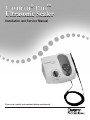
1
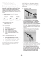
Cavitron Plus
Ultrasonic Scaler
®
™
Installation and Service Manual
Please read carefully and completely before operating unit.
TABLE OF CONTENTS
Introduction . . . . . . . . . . . 3
product overview . . . . . . . . 3
Technical support . . . . . . . . 3
supplies & replacement parts . . 3
indications for use . . . . . . . . 4
SYSTEM SETUP, OPERATION
AND TECHNIQUES FOR USE
8.1 Handpiece Setup . . . . . . . .
8.2 Patient Positioning . . . . . . .
8.3 Performing Ultrasonic .
Scaling Procedures . . . . . . .
8.4 Patient Comfort Considerations .
. 11
. 12
. 12
. 12
SYSTEM CARE
9.1 Daily Maintenance . . . . . . . . 12 .
contraindications . . . . . . . . 4
Start-up procedures .
at the beginning of the day . . . 12 .
warnings . . . . . . . . . . . . . . 4
Between patients . . . . . . . . 13 .
precautions
Shut-down procedures at .
the end of the day . . . . . . . 13 .
4.1 System Precautions . . . . . . . . 4
4.2 Procedural Precautions . . . . . 4-5
INFECTION CONTROL
5.1 General Information . . . . . . . . 5
5.2 Water Supply Recommendation . . 5
INSTALLATION INSTRUCTIONS
6.1 Water Line Requirements . . . . . 5
6.2 Electrical Requirements . . . . . . 5
6.3 Unpacking the System . . . . . . . 6
6.4 System Installation . . . . . . . . 6
6.5 Power Cord Connection . . . . . . 6
6.6 Water Supply Line Connection . 6-7
6.7 Foot Control Battery Installation/ .
Replacement . . . . . . . . . . . 7
6.8 Foot Control Synchronization . . . 7
CAVITRON® PLUS
SCALER DESCRIPTION
7.1 System Controls . . . . . . . . . . 8
7.2 Diagnostic Display Indicators and .
Controls . . . . . . . . . . . . . . 9
7.3 Handpiece / Cable . . . . . . . . 10
7.4 Cavitron® 30K™ Ultrasonic
Inserts . . . . . . . . . . . . . . 10
7.5 Wireless Foot Control Information .
and Operation . . . . . . . . . . 11
7.6 Accessories and User .
Replaceable Parts . . . . . . . . . 11
7.6.1 Accessories . . . . . . . 11
7.6.2 User Replaceable Part .
Kits . . . . . . . . . . . . 11
9.2 Weekly Maintenance . . . . . . . 13
9.3 Water Line Filter Maintenance . . 13
TROUBLESHOOTING
10.1 Troubleshooting Guide . . . 13-14
10.2 Technical Support and Repairs . 14
WARRANTY PERIOD . . . . . . . . 15
SPECIFICATIONS . . . . . . . . . . 15
CLASSIFICATIONS . . . . . . . . . . 15
DISPOSAL OF UNIT . . . . . . . . . 15
QUICK REFERENCE GUIDE . . . 16-17
TROUBLESHOOTING
& ANALYSIS . . . . . . . . . . . 18-23
DISASSEMBLY AND
SERVICE PROCEDURES . . . . . 24-27
WATER FLOW DIAGRAM . . . . . . 28
SERVICE PARTS . . . . . . . . . . 29-37
Introduction
These features combine with established features, such as
the Steri-Mate® detachable, sterilizable handpiece and swivel
cable with lavage control, low power range, and hands-free
boost mode to provide the ultimate in ultrasonic scaling
experiences for your patients, while still providing the quality
and reliability you’ve come to expect from Cavitron brand
ultrasonic systems. Congratulations!
Your decision to add the Cavitron® Plus™ Ultrasonic Scaler to
your practice represents a wise investment in good dentistry.
For over four decades, dental professionals have preferred
the clinical benefits and labor-saving advantages inherent in
Cavitron ultrasonic scalers. Clinical studies and independent
research have proven that no other method of supra- and
subgingival calculus removal can surpass the speed,
efficiency, and versatility of ultrasonic scaling. The Cavitron Plus Ultrasonic Scaler is UL/ULc certified and approved. The Cavitron Plus Ultrasonic Scaler is classified by Underwriters Laboratories Inc. with respect to
electric shock, fire, mechanical hazards in accordance with
IEC 60601 Standard. The Cavitron Plus Ultrasonic Scaler
complies with Part 15 of the FCC Rules. Operation is subject
to the following two conditions: 1) this device may not cause
harmful interference, and 2) this device must accept any
interference received, including interference that may cause
undesired operation. Cavitron Plus base FCC certification/
registration number: FCC ID: TF3-DPD73227323; IC: 4681B73227323. Cavitron Plus foot control FCC certification/
registration number: FCC ID: TF3-DPD81675; IC: 4681B81675. The term IC before the certification/registration
number signifies that the Industry Canada technical
specifications were met.
DENTSPLY Professional is an ISO 13485 registered company. All DENTSPLY Professional medical devices sold in Europe are
CE marked in conformance with Council Directive 93/42/EEC.
Website: www.professional.dentsply.com
Rx Only: This product is intended for use by qualified dental
professional healthcare providers.
Product Overview
Technical Support
The Cavitron Plus Ultrasonic Scaler is a precision engineered
and manufactured instrument. It contains controls and
components for ultrasonic scaling. The system produces
30,000 strokes per second at the ultrasonic insert’s working tip that when combined with the cavitational effect of
the coolant lavage creates a synergistic action that literally “powers away” the heaviest calculus deposits while
providing exceptional operator and patient comfort. The Cavitron Plus Ultrasonic Scaler is equipped with a
Sustained Performance System™ (SPS Technology), which
offers a constant balance between scaling efficiency and
patient comfort by maintaining clinical power when the insert
tip encounters tenacious deposits, allowing the clinician to
effectively scale even at a decreased/lower power setting.
The Cavitron Plus System has extended the SPS technology
by spreading out the Blue Zone range, providing finer
resolution to the power settings. Advanced features that
make the Cavitron Plus a wise investment include a wireless
foot control, illuminated diagnostic display, rinse setting, and
automated purge function.
For technical support and repair assistance in the U.S., call
Dentsply Professional Cavitron CareSM Factory Certified
Service at 1-800-989-8826, Monday through Friday, 8:00
A.M. to 5:00 P.M. (Eastern Time). For other areas, contact
your local DENTSPLY Professional Representative.
SupplieS &
Replacement Parts
To order supplies or replacement parts in the U.S., contact
your local DENTSPLY Professional Distributor or call 1-800-989-8826, Monday through Friday, 8:00 A.M. to 5:00
P.M. (Eastern Time). For other areas, contact your local DENTSPLY Professional Representative.
3
Section 1:
Indications For Use
•
All general supra and subgingival scaling applications
•
Periodontal debridement for all types of periodontal diseases
•
Endodontic procedures
Section 2:
Contraindications
•
Ultrasonic Systems should not be used for restorative dental procedures involving the condensation of amalgam.
Persons fitted with cardiac pacemakers, defibrillators and other active implanted medical devices, have been cautioned that some types of electronic equipment might interfere with the operation of the device. Although no instance of interference has ever been reported to DENTSPLY, we recommend that the handpiece and cables be kept 6 to 9 inches (15 to 23 cm) away from any device and their leads during use.
•
Failure to follow the recommendations for environmental operating conditions, including input water temperature, could result in injury to patients or users.
•
The use of High Volume Saliva Evacuation to reduce the quantity of aerosols released during treatment is highly recommended.
•
It is the responsibility of the Dental Healthcare Professional to determine the appropriate uses of this product and to understand the health of each patient, the dental procedures being undertaken, and industry and governmental agency recommendations, requirements, and regulations for safe practice of dentistry.
•
Where asepsis is required or deemed appropriate in the best professional judgment of the Dental Healthcare Professional, this product should not be used.
•
During boil-water advisories, this product should not be operated as an open water system (e.g. connected to a public water system). A Dental Healthcare Professional should disconnect the system from the central water source. The Cavitron DualSelect™ system can be attached to this unit and operated as a closed system until the advisory is cancelled. When the advisory is cancelled, flush all incoming waterlines from the public water system (e.g. faucets, waterlines and dental equipment) in accordance with the manufacturer’s instructions for a minimum of 5 minutes.
•
Prior to beginning treatment, patients should rinse with an antimicrobial such as Chlorhexidine Gluconate 0.12%. Rinsing with an antimicrobial reduces the chance
of infection and reduces the number of microorganisms released in the form of aerosols during treatment.
•
Per FCC Part 15.21, changes or modifications not expressly approved by the party responsible for compliance could void the user’s authority to operate this equipment.
Section 4: Precautions
Section 3: Warnings
•
4.1 System Precautions
There are a variety of pacemakers and other medically implanted devices on the market. Clinicians should contact the device manufacturer or the patient’s physician for specific recommendations. This unit complies with IEC 60601 Medical Device Standards.
•
Do not place the system on or next to a radiator or other heat source. Excessive heat may damage the system’s electronics. Place the system where air is free to circulate on all sides and beneath it.
•
The system is portable, but must be handled with care when moving.
•
Equipment flushing and dental water supply system maintenance are strongly recommended. See Section 9: System Care.
•
Close manual shut-off valve on the dental office water supply every night before leaving the office. •
The use of an in-line water filter is recommended.
•
Never operate system without fluid flowing through handpiece.
4.2 Procedural Precautions
•
4
The Cavitron Plus unit works with Cavitron inserts as
a system, and was designed and tested to deliver
maximum performance for all currently available Cavitron
and Cavitron Bellissima™ brand ultrasonic inserts. Companies that manufacture, repair or modify inserts
carry the sole responsibility for proving the efficacy and
performance of their products when used as a part of
this system. Users are cautioned to understand the
operating limits of their inserts before using in a clinical
setting.
•
Like bristles of a toothbrush, ultrasonic insert tips “wear” with use. Inserts with just 2 mm of wear lose about 50% of their scaling efficiency. In general, it is recommended that ultrasonic inserts be discarded and replaced after one year of use to maintain optimal efficiency and avoid breakage. A DENTSPLY Professional Insert Efficiency Indicator is enclosed for your use.
•
If excessive wear is noted, or the insert has been bent, reshaped or otherwise damaged, discard the insert immediately.
•
Ultrasonic insert tips that have been bent, damaged, or reshaped are susceptible to in-use breakage and should be discarded and replaced immediately.
•
Retract the lips, cheeks and tongue to prevent contact with the insert tip whenever it is placed in the patient’s mouth.
Section 6:
Installation Instructions
If the installation of your Cavitron Plus System is performed
by someone other than trained DENTSPLY Professional
Distributor personnel, care should be taken to observe the
following requirements and recommendations.
6.1 Water Line Requirements
Section 5:
Infection Control
5.1 General Information
•
As with all dental procedures, use universal precautions (i.e., wear face mask, eyewear, or face shield, gloves and protective gown).
•
For operator and patient safety, carefully practice the infection control procedures detailed in the Infection Control Information Booklet accompanying your System. Additional booklets can be obtained by calling Customer Service at 1-800-989-8826, Monday through Friday, 8:00 A.M. to 5:00 P.M. (Eastern Time). For areas outside the U.S., contact your local DENTSPLY Professional representative.
•
As with high speed handpieces and other dental devices, the combination of water and ultrasonic vibration from the Cavitron Plus Scaler will create aerosols. Following the procedural guidelines in Section 8 of this manual can effectively control and minimize aerosol dispersion. It is highly recommended that all dental water supply systems conform to applicable CDC (Centers for Disease Control and Prevention) and ADA (American Dental Association) standards, and that all recommendations be followed in terms of flushing, chemical flushing, and general infection control procedures. See Sections 6.1 and 9.
•
As a medical device, this product must to be installed in accordance with applicable local, regional, and national regulations, including guidelines for water quality (e.g. drinking water). As an open water system, such •
A water supply line with user-replaceable filter is supplied with your system. See Section 9 System Care for replacement instructions.
•
Incoming water supply line pressure to the system must be 20 psi (138kPa) to 40 psi (275kPa). If your dental water system’s supply line pressure is above 40 psi, install a water pressure regulator on the water supply line to your Cavitron Plus Ultrasonic Scaling System.
•
A manual shut-off valve on the dental water system supply line should be used so that the water can be completely shut-off when the office is unoccupied.
•
In addition to the water filter supplied, it is recommended that a filter in the dental water system supply line be installed so that any particulates in the water supply will be trapped before reaching the Cavitron system.
•
After the above installations are completed on the dental water supply system, the dental office water line should be thoroughly flushed prior to connection to the Cavitron system.
6.2 Electrical Requirements
5.2 Water Supply Recommendations
•
regulation may require this device to be connected to a centralized water control device. The Cavitron® DualSelect™ Dispensing System may be installed to allow this unit to operate as a closed water system.
5
•
Incoming power to the system must be 100 volts AC to 240 volts AC, single phase 50/60 Hz capable of supplying 1.0 amps.
•
The system power should be supplied through the AC power cord provided with your system.
6.3 Unpacking the System
6.5 Power Cord Connection
•
Verify the Main Power ON/OFF switch, located at the center front underside of the System, is set to the OFF (O) position before proceeding.
•
Insert the AC power cord into the power input on the back of the System.
•
Insert the pronged plug into an AC wall outlet.
Carefully unpack your Cavitron Plus System and verify that all components and accessories are included:
1.
2.
3. 4.
5.
6.
7.
8.
9.
10.
11.
12.
Cavitron® Plus™ Scaler with handpiece cable assembly with swivel
Detachable AC Power Cord
Wireless Foot Control
“AA” Batteries (4-Pack)
Auxiliary Cable for Foot Control
Water Line Assembly (Blue) with Filter and Quick Disconnect
Additional Water Line Filter
Steri-Mate® Detachable Sterilizable Handpiece
Steri-Mate® Grip Accessory (not shown)
Cavitron® Ultrasonic Inserts (quantity optional)
Efficiency Indicator for Cavitron Inserts
Literature Packet
6.6 Water Supply Line Connection
6.4 System Installation
•
The Cavitron Plus System is designed to rest on a level surface. Be sure unit is stable and resting on four feet.
•
Placing unit in direct sunlight may discolor plastic housing.
•
The system has been equipped with a wireless foot control which was factory synchronized to operate with the system’s base unit. If your office contains more than one Cavitron Plus system, it is recommended that you mark the foot control and base unit for easy reference as to which foot control operates with which base unit. Should resynchronization be necessary, follow the instructions in Section 6.8.
6
•
Grasp the Water Supply Line (blue hose) by the end
opposite the quick-disconnect and insert it into the water
inlet connector until fully seated.
•
Connect the quick disconnect to the dental office water
supply or a Cavitron DualSelect Dispensing System.
•
Inspect all connections to make certain there are no leaks.
•
To remove the water line from the Cavitron Plus System, turn off the dental office water supply. Disconnect the water supply line from the dental office water supply. If a quick-disconnect connector is attached to the end of the hose, relieve the water pressure by pressing the tip of the connector in an appropriate container and allow water to drain. To remove the hose from the system, push on the outer ring of the system’s water inlet and gently pull out the water line.
6.8 Foot Control Synchronization
The wireless foot control supplied with your system has been
factory synchronized with the base unit. Should a replacement
foot control be necessary, synchronization will be required
prior to system operation. Perform the following steps to
synchronize the foot control with the base unit.
1.
2.
Press ring to release
water supply tube.
Turn the Main Power switch located at the center front underside of the system to the OFF (O) position.
Install a new set of “AA” batteries into the foot control (See Section 6.7) Leave the battery cover of the foot control open so the red push button is accessible.
6.7 Foot Control Battery
Installation/Replacement
•
Turn foot control over and using a Philips screwdriver carefully remove battery cover screw and battery cover. If applicable, remove used batteries and install two new “AA” batteries as shown. Do not depress foot control while installing batteries. •
The communication light will blink for approximately
two seconds to indicate the foot control’s ability to
communicate with the unit. If the light does not blink,
check the batteries. If the batteries are good and
the light doesn’t blink, a communications error may
exist. Re-establish communication with Foot Control
Synchronization procedure Section 6.10.
Look for blinking
communications
light.
•
The remote frequency communication can be bypassed
using the auxillary foot control cable. Refer to Section
10.2 Technical Support and Repair for further action.
•
Replace the battery cover and screw and hand tighten
with Philips screwdriver.
•
Remove batteries if foot control is to be stored for an extended period of time.
7
3.
4.
5.
Maintain a distance of no more than 10 feet between
the base unit and foot control during the synchronization process.
Turn the Main Power switch to the ON (I) position and wait for the Diagnostic Display graphics to light (refer to Section 7.2).
While all graphics are lit, press the Purge button,
located on the Diagnostic Display. The graphics will
begin to blink in a sequential pattern, representing
the synchronization mode. This mode will last 5 to 6
seconds.
During this mode, press the red button located in the battery compartment of the foot control. This will complete the synchronization process.
Synchronization is successful when all graphics blink at the same time.
To verify proper communication, press the foot control to the Boost position (foot control fully pressed – 2nd position) and ensure the Boost graphic on base unit lights.
Replace battery cover and the screw.
6.
7.
8.
9.
Section 7: Cavitron Plus Scaler Description
7.1 System Controls
Ultrasonic Power Level Control
Turn knob to select the ultrasonic power level for operation. Turning the knob clockwise
increases the distance the insert tip moves (stroke) without changing the frequency; turning
the knob counterclockwise decreases the distance the insert tip moves (stroke) without
changing the frequency.
The Blue Zone is a low-power range for effective subgingival debridement and improved
patient comfort during definitive therapy.
inse
R
Turn ultrasonic power level control knob fully counterclockwise until a “click” is heard. Rinse
mode is for use during an ultrasonic scaling procedure when lavage is desired with minimal
cavitation. Handpiece
Operates all
Cavitron® 30K™
Ultrasonic inserts
and transmits
power and lavage
from the system to insert.
Diagnostic
Display
ee Section
S
7.2.
Handpiece Holder
ecurely holds the
S
system’s handpiece
(with or without insert)
when the system is
not in use. Also holds
cable connector when
handpiece is not installed.
Main Power ON/OFF Switch
N/OFF Switch located at the center front underside of the
O
system. Dual Position
Foot Control
See Section 7.5
8
7.2 Diagnostic Display Indicators and Controls
Blue Zone Indicator
ights when the Power Level Control is positioned
L
in the Blue Zone of the power scale. Ideal for effective subgingival debridement and greater patient comfort.
Rinse Indicator
ights when the Power
L
Level Control is turned
fully counterclockwise. Rinse mode provides
lavage to flush the
procedural area with
negligible tip movement.
Boost Indicator
ights when the L
Boost Mode has been activated.
Low Battery
Indicator
ights when the foot
L
control battery power
is approaching end of
life. Replace batteries as instructed in
Section 6.7.
Service Indicator
Lights when the system is
not functioning properly.
This diplay has three
distinct modes.
• A fast blink (3 blinks per second) indicates an improper set-up.
Power Indicator
Lights (3 Sec. delay)
when the Main Power
ON/OFF Switch is ON
(“I” position).
• A slow blink (1 blink per second) means the system is operating out of factory specifications.
• A steady light indicates the system is overheating.
Refer to Section 10.1 for
Troubleshooting guidelines.
Purge Control
ights when the Purge function is activated. L
To activate Purge, remove insert from the handpiece, and press the Purge button. Water will purge through system for 2 minutes. For optimal efficiency, turn the handpiece lavage control to maximum water flow. To
deactivate mode during the 2 minute cycle, press Purge button again or press foot control.
The Purge Control is also used during the Foot Control
Synchronization process. See Section 6.8.
9
7.3 Handpiece / Cable
Lavage Control
Turn the Lavage Control to select flow rate during
system operation. Clockwise increases flow at insert tip,
counterclockwise decreases flow. The flow rate through the
handpiece also determines the temperature of the lavage. Lower flow rates produce warmer lavage. Higher flow rates
produce cooler lavage. If the handpiece becomes warm, increase the flow rate. With experience, the Dental Healthcare Professional will be
able to determine the best flow rate setting for optimum
operating efficiency and patient comfort.
Steri-Mate®
Handpiece
Swivel Feature
Reduces cable drag as handpiece rotates during procedures.
Steri-Mate Grip Accessory (not shown)
The Steri-Mate Grip provides an ergonomic and comfortable
grasp of the handpiece. The grip is sterilizable and is
available in several different colors as an accessory for your
Steri-Mate Handpiece. See installation instructions provided
with the grip.
7.4 Cavitron 30K Ultrasonic Inserts
The many styles of Cavitron and Cavitron Bellissima 30K Ultrasonic Inserts are easily interchangeable for various procedures
and applications. See enclosed literature for specific information.
O-Ring
Provides seal for handpiece coolant. O-ring should be replaced when worn.
Insert Tip
Shape and size of tip determines access and adaptation. Preheated Lavage
directed to tip.
Finger Grip
Connecting Body
Transfers and amplifies mechanical motion of stack to insert tip.
Insert Marking
Manufacturer, Date
(YDDD=Single Digit Year
and Triple Digit Day of
the Year), Frequency,
Type, Tip Lot Number (if applicable)
10
Magnetostrictive Stack
Converts energy provided by the handpiece
into mechanical oscillations used to activate
the insert tip.
Section 8: System Setup,
Operation and Techniques
for Use
7.5 Wireless Foot Control
Information and Operation
The foot control is a two-positioned momentary switch. The first position activates both the ultrasonic energy and
lavage at the insert tip. The second position activates the
Boost Mode. The Boost Mode (fully depressed foot control)
increases the ultrasonic power level for quick, efficient
removal of tenacious deposits without touching the system
base. To deactivate Boost Mode, release foot control to first
position. •
8.1 Handpiece Setup
Pressing anywhere on the top of the foot control
activates the system. DEPRESSED
DEPRESSED
NON-DEPRESSED
1st POSITION
2nd POSITION
7.6 Accessories and User
Replaceable Part
7.6.1 Accessories
1. 2. 3. 4. 5. 6. 7. AC Power Cord
Dual Position Foot Control (Wireless)
Auxiliary Foot Control Cable
Cavitron 30K Ultrasonic Inserts
Cavitron DualSelect Dispensing system
Cavitron Steri-Mate Sterilizable Handpiece
Cavitron Steri-Mate Grip (Available in a variety of colors)
7.6.2 User Replaceable Part Kits
1.
2.
3.
Cavitron Insert Replacement O-ring 12/Packs
PN: 62351 (black) for plastic and Bellissima inserts
PN: 62605 (green) for metal grips and prophy
Steri-Mate Handpiece Cable O-ring, PN: 79357
Lavage (Water) Filter, 10/Pack, PN: 90158
For detailed information, contact your local DENTSPLY
Professional Representative or authorized DENTSPLY
Professional Distributor.
11
•
Connect the Handpiece to the Cable Assembly by aligning the electrical connections. If Cable Assembly does not seat into the handpiece, gently rotate the handpiece until contacts align, then fully insert handpiece.
•
Hold empty handpiece in an upright position over a sink or drain. Activate the Foot Control until water exits to bleed any air bubbles that might be trapped inside the handpiece.
•
Lubricate the O-ring on the insert with water before placing it into the handpiece. Fully seat insert with a gentle push-twist motion. DO NOT FORCE.
•
Turn the Lavage Control to select flow rate during system operation. Clockwise increases flow at insert tip, counterclockwise decreases flow. The flow rate through the handpiece also determines the temperature of the lavage. Lower flow rates produce warmer
lavage. Higher flow rates produce cooler lavage. If the handpiece becomes warm, increase the flow rate. With experience the Dental Healthcare Professional will be able to determine the best flow rate setting for optimum operating efficiency and patient comfort.
8.2 Patient Positioning
8.4 Patient Comfort Considerations
For optimal access to both the upper and lower arches, the
backrest of the chair should be adjusted as for other dental
procedures. This assures patient comfort and clinician
visibility.
Reasons for sensitivity
•
Incorrect tip placement. The point should never be directed toward tooth root surfaces.
Have the patient turn his/her head to the right or left. Also
position chin up or down depending upon the quadrant and
surface being treated. Evacuate irrigant using either a saliva
ejector or High Volume Evacuator (HVE).
•
Not keeping tip in motion on tooth. Do not allow the insert to remain in a static position on any one area of the tooth. Change the insert’s path of motion.
•
Applying excessive pressure. Use a very light grasp and pressure, with a soft tissue fulcrum whenever possible, especially on exposed cementum.
•
If sensitivity persists, decrease power setting and/or move from the sensitive tooth to another and then return.
8.3 Performing Ultrasonic
Scaling Procedures
Note: Refer to the Infection Control Information
booklet supplied with your system and Section 9 of
this manual for general procedures to be followed
at the beginning of each day and between patients.
Section 9: System Care
It is recommended that you perform the following maintenance
procedures to help maximize water quality and to be in
compliance with CDC guidelines for infection control. •
The edges of Cavitron Ultrasonic Inserts are intentionally rounded so there is minimal danger of tissue laceration with proper ultrasonic scaling technique. Whenever the insert tip is placed in the patient’s mouth, the lips, cheek and tongue should be retracted to prevent accidental (prolonged) contact with the activated tip.
•
Turn Power Level Control to select ultrasonic power level for operation. Clockwise increases system power. Power level will increase throughout the full range of the control. Hold the handpiece over a sink or drain. Press the foot control to activate the system. Check spray to verify fluid is reaching the working end of the insert tip. Adjust the Lavage Control to ensure adequate
flow for the selected power setting. Greater flow settings
provide cooler irrigation.
•
It may be necessary to adjust lavage with the system in
“Boost” mode (Foot Control fully depressed) so adequate
fluid will be available to cool tip to tooth interface.
•
In general, it is suggested that a “feather-light-touch” be used for ultrasonic scaling. The motion of the activated tip and acoustic effects of the irrigating fluid, in most cases, are adequate to remove even the most tenacious calculus.
•
Periodically check the Cavitron Ultrasonic Insert for wear with the Cavitron Insert Efficiency Indicator.
•
The use of a saliva ejector or High Volume Evacuator (HVE) is recommended during all procedures.
•
Set the system’s Power Level Control to the lowest efficient power setting for the application and the selected insert.
9.1 Daily Maintenance
12
Start-Up Procedures at the beginning of the day:
1.
2.
3.
4.
5. 6. 7. Open the manual shut-off valve on the dental office water supply system.
Install a sterilized Steri-Mate handpiece on the handpiece cable.
Turn Main Power Switch to the ON (I) position. Verify the ON/OFF indicator light is lit. Set the Power Level Control to the minimum setting (not rinse).
Set the Lavage Control on the handpiece cable to maximum.
Hold the Handpiece (without an insert installed)
upright over a sink or drain. Activate the Purge Control button.
• The Purge button will light for two minutes indicating activation of the purge function.
• If the Purge button is activated with an insert present in the handpiece, the button will blink for 3 seconds and disable. Remove the insert from the handpiece and press the Purge button again.
• The Purge function can be interrupted at any time by pressing the Purge button again or by pressing the foot control.
After completing the purge cycle, place a sterilized insert into the Handpiece and set the Ultrasonic Power Level Control and Lavage Control to your preferred operating position.
Use manual. If connected to another device, please follow
those directions for use, keeping in mind that a chemical
flush should be performed at maximum water flow for at least
30 seconds. The system should be left undisturbed for 10
minutes but no more than 30 minutes to allow the sodium
hypochlorite solution to soak in the lines. As a suggestion, it
is recommended that a sign be placed on the system stating
that the SYSTEM IS BEING DISINFECTED WITH A STRONG
DISINFECTANT AND SHOULD NOT BE USED. When ready,
flush system with clean water for at least 30 seconds or
until sodium hypochlorite odor disappears. ALL CHEMICALS
MUST BE FLUSHED FROM THE SYSTEM BEFORE IT IS READY
FOR PATIENT USE.
Between Patients:
1. Remove ultrasonic insert used. Clean and sterilize the ultrasonic insert(s) following the procedures
outlined in the Cavitron Ultrasonic Insert Infection Control Direction for Use enclosed with every insert. 2. Hold the handpiece over a sink or drain and activate
Purge function as described in Step 6 of Start-Up Procedures.
3. After the purge cycle is complete, turn the system
OFF, (O) position.
4. Remove the Steri-Mate handpiece. Clean and sterilize
the handpiece following the procedure outlined in the
booklet enclosed with your unit.
5. Disinfect the surfaces of the cabinet, Power Cord,
Handpiece Cable, Water Supply Line, Foot Control
and Auxillary Cable (if applicable) by applying an
approved non-immersion type disinfectant solution*
carefully following the instructions provided by the
disinfectant solution manufacturer. To clean System,
generously spray disinfectant solution on a clean
towel and wipe all surfaces. Discard used towel. Dry
with a clean cloth. To disinfect system, generously
spray disinfectant on a clean towel and wipe all
surfaces. Allow disinfectant solution to air dry. Never
spray disinfectant solution directly on the system.
6. Inspect the handpiece cable for any breaks or tears.
7. If using a closed water supply or DualSelect Dispensing system, check for adequate fluid volume for the next patient.
8. When ready for use, place a sterilized Steri-Mate
handpiece on the handpiece cable and a sterilized
insert into the handpiece and adjust system controls
to preferred operator positions.
9.3 Water Line Filter Maintenance
When the water line filter becomes discolored, the filter
should be replaced to prevent reduced water flow to the
Cavitron Plus Ultrasonic Scaler. A 10-pack of replacement
filters is available by ordering Part Number 90158 from your
local authorized DENTSPLY Distributor.
Shut-Down Procedures at the end of the day:
Follow the “Between Patients” maintenance procedures,
Steps 1 through 6. In addition, it is recommended to close
the manual shut-off valve on the dental water supply system.
1.
2.
3.
4.
5.
Verify system is turned OFF.
Disconnect the water supply hose from the water source. If a quick-disconnect connector is attached to the end of the hose, relieve the water pressure by pressing the tip of the connector in an appropriate container to drain the water.
Grasp the fitting on either side of the filter disk and twist counterclockwise. Remove the filter section from either side of the water hose.
Install the replacement filter onto the water hose fittings. The filter should be positioned to match up with the correct hose fitting.
Hand tighten the two hose fittings in a clockwise direction. Reconnect the water supply hose, operate the unit to bleed the air and test for leaks.
Section 10:
Troubleshooting
Although service and repair of the Cavitron Plus Ultrasonic
Scaler should be performed by DENTSPLY personnel, the
following are some basic trouble shooting procedures that
will help avoid unnecessary service calls. Generally, check all
lines and connections to and from the System, a loose plug
or connection will often create problems. Check the settings
on the System’s controls.
*NOTE: Water-based disinfection solutions are
preferred. Some alcohol-based disinfectant
solutions may be harmful and may discolor
plastic materials.
9.2 Weekly Maintenance
It is strongly recommended that this system be disinfected
by chemically flushing the waterlines with a 1:10 Sodium
Hypochlorite solution (NaOCl) at the end of each week.
This can be accomplished by connecting this device to the
Cavitron DualSelect Dispensing System or a number of other
devices available from your local distributors. Where this
device is connected to the Cavitron DualSelect Dispensing
System, please follow the DualSelect system’s Directions for
10.1 Troubleshooting Guide
Symptom:
System will not operate: No Power ON indicator
13
1. Check that the Main Power Switch is in the ON (l) position, and that the detachable Power Cord is fully seated in the receptacle on back of System.
Symptom:
2. Check that the system’s power cord plug is fully seated in an approved AC wall outlet.
3. Check that the wall outlet is functional.
System operates: Service Indicator blinking
• Slow Blinking (1 blink per second) The system is not operating within factory specifications.
1. Remove insert.
2. Turn Main Power Switch OFF, (O) position. Wait five
seconds. Turn unit ON, (I) position.
3. Operate Purge function.
4. If service indicator still blinks, refer to Section 10.2 Technical Support and Repairs to have unit serviced as soon as possible.
• Fast Blinking (3 blinks per second) – Indicates improper set-up
1. If insert is in the handpiece, remove. Verify the handpiece is properly seated and depress the foot control for 2 seconds. If blinking stops, the system is ready for use. If blinking remains, continue to the next step.
2. Attach a NEW handpiece and depress foot control for 2 seconds. If blinking stops, the system is ready for use. Discard the old handpiece or return if
within warranty. If blinking remains, continue to the next step.
3. Install and fully seat an insert into handpiece. Depress foot control for 2 seconds. If blinking stops, unit is ready for use. If blinking remains, continue to the next step.
4. Install and fully seat a NEW insert in handpiece and
depress foot control for 2 seconds. If blinking
stops, system is ready for use. Discard old insert
or return if within warranty. If blinking remains,
refer to Section 10.2 Technical Support and
Repairs to have unit serviced as soon as possible.
Symptom:
System will not operate: Power ON Indicator is
illuminated
1. If the office has more than one foot control, test each
to ensure that the proper foot control is being used.
With a handpiece and insert installed, depress the
foot control to the first position. The system should
dispense water. If none of the foot controls operate
the system, continue to the next step.
2. Resynchronize one foot control to the system (see
Section 6.8 Foot Control Synchronization).
Symptom:
System operates: No water flow to insert tip
1.
2.
3.
4.
5.
Assure that handpiece lavage control is properly adjusted.
Check for clogged insert.
Check that dental office water supply valves are open.
If the system is connected to DualSelect Dispensing System, check that fluid level in the selected bottle is sufficient. Make sure valves are open when using external water source.
Check that the water line filter is clean. Replace filter if needed.
Symptom:
System operates: No insert cavitation
1. Check that the Power Level Control is not in Rinse
Mode.
2. Check the insert for damage and that it is properly installed in the handpiece.
3. Check that the handpiece is properly installed to the cable assembly.
4. If Steri-Mate grip is used on the handpiece, verify that the grip is flush with the hard plastic of the insert port.
5. Turn the system’s Main Power Switch to the OFF (0) position. Wait 5 seconds and turn the system back ON.
6. If problem still exists, replace both “AA” batteries in foot control with new “AA” batteries (Refer to Section 6.7) or connect auxiliary foot control cable.
Symptom:
System operates: Service Indicator illuminated
1. Ensure that the base unit has adequate ventilation and is not near a heat source (i.e. radiator, heat lamp, sunlight or other heat producing operatory equipment).
2. Turn Main Power Switch to the OFF (O) position. Allow
system to cool for 10 minutes and turn system ON, (I)
position. Verify light is not illuminated.
3. If light is still illuminated, refer to Section 10.2 Technical Support and Repairs to have unit serviced as soon as possible.
Symptom:
System operates: Purge Mode will not function
– icon flashing
10.2 Technical Support and Repairs
1. Check that there is no insert in the handpiece.
2. Check that handpiece is properly installed to the cable assembly.
For technical support and repair assistance call DENTSPLY
Professional Cavitron CareSM Factory Certified Service at 1800-989-8826 Monday through Friday, 8:00 A.M. to 5:00
P.M. (Eastern Time). For areas outside the U.S., contact your
local DENTSPLY Professional representative.
14
Section 11:
Warranty Period
The Cavitron Plus Ultrasonic Scaler is warranted for TWO YEARS from date of purchase. The Steri-Mate Handpiece enclosed
with your system is warranted for SIX MONTHS from date of purchase. Refer to the Warranty Statement Sheet furnished with
your system for full Warranty Statement and Terms.
Section 12: Specifications
Electrical Voltage
Continuous (100-240 VAC)
Current
1.0 Amperes, Maximum
Phase
Single
Frequency
50/60 Hertz
Water Pressure
20 to 40 psig (138 to 275 kPa)
Water Flow Rate
Minimum Setting (CCW) < 15 ml/min
Maximum Setting (CW) > 55 ml/min
Weight
3.3 lbs (1.5 Kg)
Dimensions
Height: 5 in (12,7 cm)
Width: 9.5 in (24,13 cm)
Depth: 8 in (20,32 cm)
Handpiece Cable length: 6.5 ft. (2.0 M)
Auxillary Foot Control Cable length: 8ft. (2.4 M)
Water Supply Line length: 8 ft. (2.4 M)
Foot Control Protection Class IPX1. Not for operating theatres.
Remote Communication Frequency:
Power: Channels:
Operating Environment
Temperature: 15 to 40 Deg. Celsius (59 to 104 Deg. Fahrenheit)
Relative Humidity: 30% to 75% (non-condensing)
Transport and Storage Conditions
Temperature: -40 to 70 Deg. Celsius (-40 to 158 Deg. Fahrenheit)
Relative Humidity: 10% to 100% (non-condensing)
Atmospheric Pressure: 500 to 1060 hPa
2405 to 2480 MHz
< 1mW
16
Section 13: Classifications
• Type of protection against electric shock: • Degree of protection against electric shock: • Degree of protection against the harmful ingress of water:
• Mode of operation: • Degree of safety of application in the presence of a flammable
anaesthetic mixture with air or with oxygen or nitrous oxide: Section 14: Disposal of Unit
• Accordance with local and state laws.
15
Class 1
Type B
Ordinary
Continuous
Equipment not suitable for use in the presence of flammable anaesthetic or oxygen. IIA (rule 9)
(ISO/IEC 60601)
Cavitron Plus Ultrasonic Scaler
Quick Reference Guide
Diagnostic Display
ON/OFF
Illuminates when the Main Power On/Off switch is in the “ON” position.
.
BLUE ZONE
Illuminates when the ultrasonic power control is positioned in the Blue Zone
of the power scale. The Blue Zone extended low-power range is effective for
subgingival debridement and greater patient comfort during definitive therapy.
RINSE
Illuminates when the ultrasonic power level control is turned fully
counterclockwise. With an insert in the handpiece, activate the Foot
Control and lavage will occur with negligible tip movement.
PURGE
Boost
Illuminates when the Boost Mode is activated by the Foot Control. To
activate, fully depress Foot Control to the second position. To deactivate
Boost Mode, release Foot Control to first position.
PURGE button
Illuminates when the Purge function is activated. To activate Purge, remove insert from the handpiece,
press the Purge button on the Diagnostic Display and water will purge through system lines for two
minutes. For optimal efficiency, turn the Handpiece Lavage Control to maximum water flow. To
deactivate during the two minute cycle, press Purge button again or press Foot Control.
SERVICE
Lights when the system is not functioning properly. This display has three distinct modes:
•
Slow blink (1 blink per second) means the system is not operating within factory specifications.
•
Fast blink (3 blinks per second) indicates an improper set-up.
•
Steady light indicates the system is overheating.
Refer to Troubleshooting guidelines on reverse side.
LOW BATTERY
Illuminates when the Foot Control battery power is approaching end of life. Replace batteries as
instructed in the Directions for Use.
Power Control
POWER LEVEL CONTROL
Turn knob to select ultrasonic power level for operation. Turning the knob clockwise increases the
distance the insert tip moves (stroke) without changing the frequency; turning the knob counterclockwise
decreases the distance the insert tip moves (stroke) without changing the frequency.
RINSE
Rinse mode is used during an ultrasonic scaling procedure when lavage is required to flush the procedural
area. To activate, turn Power Level Control fully counterclockwise until a “click” is heard. BLUE ZONE
Provides an extended low-power range for effective subgingival debridement and greater patient comfort
during definitive therapy.
16
QUICK REFERENCE GUIDE TROUBLESHOOTING
SYMPTOM ACTION TAKEN
System will
not operate:
No Power ON
Indicator
1. 2.
3.
Check that the Main Power Switch is in the ON (I) position, and that the detachable power cord is fully seated in the receptacle on back of system. Check that the system’s power cord plug is fully seated in an appropriate AC wall outlet.
Check that the wall outlet is functional.
System will
not operate:
Power ON
Indicator is
illuminated
1. If the office has more than one foot control, test each to ensure that the proper foot control is
being used. With a handpiece and insert installed, depress the foot control to the first position. The system should dispense water. If none of the foot controls operate the system, continue to the next step.
Resynchronize one foot control to the system (see Directions for Use Section 6.8 Foot Control
Synchronization).
System operates:
No water flow to
insert tip
1.
2.
3.
4.
5.
Assure that handpiece lavage control is properly adjusted.
Check for clogged insert; Replace insert if necessary.
Check that dental office water supply valves are open.
If the system is connected to DualSelect Dispensing System, check that fluid level in theselected bottle is sufficient. Make sure valves are open when using external water source.
Check that the water line filter is clean; Replace filter, if needed.
System operates:
No insert
cavitation
1.
2.
3.
4.
5.
6.
Check that the Power Level Control is not in Rinse Mode.
Check the insert for damage and that it is properly installed in the Handpiece.
Check that the handpiece is properly installed to the cable assembly.
Verify that the handpiece’s soft grip is flush with the hard plastic of the insert port.(Skip this step if not using Soft Grip Accessory)
Turn the system’s Main Power Switch OFF, (O) position. Wait 5 seconds and turn the system back ON.
If problem still exists, replace both “AA” batteries in foot control with new “AA” batteries, or connect Auxiliary Foot Control Cable.
Service
indicator
blinking
1.
2.
Slow blinking (1 blink per second) - The system is not operating within factory specifications.
A. Remove insert.
B. Turn Main Power Switch OFF, (O) position. Wait five seconds. Turn switch ON, (I) position.
C. Operate Purge function.
D. If service indicator still blinks, refer to Technical Support and Repairs to have unit serviced as soon as possible.
Fast blinking (3 blinks per second) – Indicates improper set-up
A. If insert is in the handpiece, remove. Verify the handpiece is properly seated and depress the foot control for 2 seconds. If blinking stops, the system is ready for use. If blinking remains, continue to the next step.
B. Attach a NEW handpiece and depress foot control for 2 seconds. If blinking stops, the system is ready for use. Discard the old handpiece or return if within warranty. If blinking
remains, continue to the next step.
C. Install and fully seat an insert into handpiece. Depress foot control for 2 seconds. If blinking stops, unit is ready for operation. If blinking remains, continue to the next step.
D. IInstall and fully seat a NEW insert in handpiece and depress foot control for 2 seconds. If blinking stops, system is ready for use. Discard old insert or return if within warranty. If blinking remains, refer to Technical Support
System operates:
Service indicator
illuminated
1.
2.
3.
Ensure that the base unit has adequate ventilation and is not near a heat source (i.e. radiator, heat lamp, sunlight or other heat producing operatory equipment).
Turn Main Power Switch OFF, (O) position. Allow system to cool for 10 minutes and turn system ON, (I) position. Verify light is not illuminated.
If light is still illuminated, refer to Technical Support and Repairs to have unit serviced as soon as possible
System operates:
Purge mode will
not function -icon flashing
1.
2.
Check that there is no insert in the handpiece.
Check that handpiece is properly installed to the cable assembly.
2.
17
Section 16: Cavitron® Plus™ Troubleshooting and Analysis
This troubleshooting section is meant for use by qualified Cavitron® Service Technicians.
SYMPTOMS
Cavitron Plus™ scaler does
not power up: pilot light does
not illuminate.
®
CAUSES
CORRECTIVE MEASURES
1. Faulty wall outlet.
1. Check wall outlet and if faulty take necessary corrective measures.
2. Damaged power cord.
2. Replace the power cord.
3. Fuse F3 and/or F4 blown.
3. Replace internal fuses F3 and F4 with specified fuses.
4. Damaged On/Off switch.
4. Replace the On/Off switch.
Slo-Blo Fuses good. No power
to circuitry.
1. Unit is installed in a confined area 1. Provide adequate air circulation around unit.
(such as a cabinet), or is too close to a heat source to insure proper air circulation around unit.
Slo-Blo Fuse F3 and/or F4
Failed.
1. Short in Power supply assembly.
1. Replace the Power Supply assembly.
2. Short in Power Drive PC Board assembly.
2. Replace the Power Drive PC Board assembly.
Low insert scaling power or
insert stops vibrating when
contacting tooth surface.
1. Insert malfunction.
1. Test with another Cavitron® insert. If test insert works properly, discard the original insert.
2. Insert is not pushed in far enough 2. a. Check if insert is fully seated in the handpiece.
for automatic pick-up.
b. If a handpiece soft grip is being used, verify that the grip is flush with the hard plastic of the
insert port. Refer to the Installation Instructions provided with the soft grip for correct installation.
3. Unit improperly calibrated.
3. a. Return scaler to DENTSPLY® for factory certified service.
b. Refer to DENTSPLY® Professional Division- Product Service SOP PS-153.
18
Cavitron® Plus™ Troubleshooting and Analysis, continued
This troubleshooting section is meant for use by qualified Cavitron® Service Technicians.
SYMPTOMS
Intermittent scaling power or no
scaling power.
CAUSES
CORRECTIVE MEASURES
1. Insert malfunction.
1. Test with another Cavitron® insert. If test insert works properly, discard the original insert.
2. Insert is not pushed in far enough for automatic pick-up.
2. a. Check if insert is fully seated in the handpiece.
3. Malfunction in Steri-Mate™ Handpiece.
3. Replace Steri-Mate™ Handpiece.
4. Bent or missing electrical pin in Steri-Mate™ Handpiece.
4. Replace Steri-Mate™ Handpiece.
5. Open or intermittent wires in handpiece cable assembly.
5. Install a working Steri-Mate™ Handpiece on the cable. Unplug the Handpiece cable connector at J3 of the Power Drive PC Board and check the continuity of the wires.
a. Connect the ohmmeter between RED-GRN wire terminals. Flex the handpiece cable and check for intermittent readings. If the ohmmeter reading is not consistent or it is indicating an open circuit, the handpiece cable assembly is likely to be damaged and should be replaced.
b. If a handpiece soft grip is being used, verify that the grip is flush with the hard plastic of the insert port. Refer to the Installation Instructions provided with the soft grip for correct installation.
b. Connect the ohmmeter between WHT-GRN wire terminals and repeat the procedure above.
6. Loose wiring or defective solder 6. Troubleshoot the unit wiring and connectors.
joint in the unit wiring
7. Foot Control battery weak.
7. a. Check information center for Low Battery
light indication. Replace battery as needed.
b. Connect an auxiliary Foot Control cable between the Foot Control and the unit. The unit can be operated with the cable until the battery is replaced.
8. Foot Control not synchronized to the unit.
19
8. a. Follow Directions for Use & Service Manual
instructions for Foot Control synchronizing.
b. Connect the auxiliary Foot Control cable between the Foot Control and unit. Unit can be operated with the cable until the Foot Control is
synchronized.
Cavitron® Plus™ Troubleshooting and Analysis, continued
This troubleshooting section is meant for use by qualified Cavitron® Service Technicians.
SYMPTOMS
CAUSES
CORRECTIVE MEASURES
Intermittent scaling power or no 9. Foot Control malfunction.
scaling power.
(Continued)
Handpiece heats up.
9. Connect the auxiliary Foot Control cable between the Foot Control and the unit. If the unit will not operate with the auxiliary cable connected, replace
the Foot Control. Follow the Directions for Use and Service Manual instructions for Foot Control synchronizing.
1. Insufficient water to cool handpiece.
1. Increase the setting on the handpiece lavage control until handpiece runs cool.
2. Air trapped in the handpiece.
2. When the inserts are changed, hold the handpiece in an upright position until the trapped air is removed and the water flows properly.
3. Insert water passageway clogged. 3. Replace the Cavitron® insert and check operation.
4. Handpiece cable not supported during procedure.
4. Loop handpiece cable around arm or support with finger to prevent water restriction.
5. Worn insert being used.
5. Replace with a new Cavitron® insert. Worn inserts require higher power settings producing more heat.
Insert vibrates but no water or
1. Low incoming dental office water 1. Measure water pressure at dental office.
insufficient water flows from the pressure.
Adjust incoming source water pressure to handpiece.
specification. Water pressure should be 20-40 psi.
2. Water filter clogged.
2. Replace the water filter when discolored or restriction occurs.
3. Handpiece cable water tubing and 3. Remove restriction if possible or replace wires twisted.
handpiece cable assembly.
4. Damaged handpiece cable Flow Control.
4. Replace handpiece cable assembly.
5. Obstruction or mineral deposits in 5. a. Remove the insert and turn the water valve
the water system in the unit.
full open. Observe the water flow. If the flow is good then the obstruction is in the insert.
b. If the obstruction is not in the insert, then
remove the handpiece water line at solenoid and check the water flow. If flow is good, then
the obstruction is in handpiece supply line.
20
Cavitron® Plus™ Troubleshooting and Analysis, continued
This troubleshooting section is meant for use by qualified Cavitron® Service Technicians.
SYMPTOMS
CAUSES
CORRECTIVE MEASURES
No water flow from handpiece
with no insert installed.
1. High dental office water pressure. 1. Install a water pressure regulator on the main water supply line and reduce the pressure to 20-40 psi.
Water spray from insert is not
properly covering the operating
area of the activated tip.
1. Improper water flow adjustment.
1. Refer to “Instructions For Using DENTSPLY® Cavitron® Plus™ Ultrasonic Dental Unit” for instructions on water flow adjustment.
2. P-style insert water tube incorrectly aimed.
2. Use small smooth pliers, reposition the water tube and direct the spray at the back of the insert tip.
3. Insert is partially clogged.
3. Replace the insert.
Water drips from the handpiece
when not operating.
1. Water solenoid valve leaking due 1. Try plugging the water supply hose into an air to trapped debris.
source to blow out the dirt. If the leak persists, replace the regulator/solenoid assembly. Be sure the external hose filter is installed.
Water leak from the handpiece
while in operation.
1. O-ring worn on insert.
1. Replace the o-ring with genuine Cavitron® o-rings. O-rings are available in packs of 12: Green O-Rings P/N 62605 Black O-Rings P/N 62351
2. Water leak in plastic water line at handpiece or inside the SteriMate™ Handpiece.
2. a. Unplug the Steri-Mate™ handpiece from the cable and replace the small o-ring on the connector. Part No. 79357 (12-Pack)
b. Replace the Steri-Mate™ handpiece and/or cable assembly.
Water flow not controllable
by turning the handpiece flow
control knob.
1. Malfunction of water regulator / solenoid assembly.
1. Replace the water regulator / solenoid valve assembly. Adjust the water regulator to specifications.
Intermittent activation or no
activation when stepping on the foot control.
1. Foot Control battery is weak.
1. a. Check Foot Control battery condition. Replace battery as required.
b. Connect the auxiliary Foot Control cable between the Foot Control and unit. The unit can be operated with the cable until the battery is replaced.
21
Cavitron® Plus™ Troubleshooting and Analysis, continued
This troubleshooting section is meant for use by qualified Cavitron® Service Technicians.
SYMPTOMS
CAUSES
CORRECTIVE MEASURES
Intermittent activation or no
activation when stepping on the
foot control.
2. Foot Control is not synchronized to the base unit.
(Continued)
2. a. Follow the Directions for Use and Service Manual instructions for Foot Control synchronization.
b. Connect the Auxiliary Foot Control cable between the Foot Control and the unit. The unit can be operated with the cable until the Foot Control is re-synchronized.
3. Malfunction in the Foot Control.
3. Replace the Foot Control. Follow the Directions for Use and Service Manual instructions for Foot Control synchronization.
Boost Power mode does
not activate. Information
Center “Boost” LED does not
illuminate.
1. Foot Control not fully depressed.
1. Depress the Foot Control fully. The “Boost” LED should illuminate.
2. The Foot Control is defective.
2. Replace the Foot Control. Follow the Directions for Use and Service Manual instructions for Foot Control synchronization.
Inserts cannot be installed in
the handpiece properly.
1. O-ring on the insert is dry.
1. Lubricate the o-ring with water. If the o-ring is worn, replace it.
2. Incorrect or damaged O-ring installed on the insert
2. Replace the insert O-ring with Cavitron® O-rings. O-rings are available in packs of 12: Green O-Rings P/N 62605 Black O-Rings P/N 62351
1. Scaling insert is installed in the handpiece.
1. Purge mode will only operate with the handpiece empty. Remove the insert and re-press the Purge button.
Purge modes does not activate
and the Purge light blinks five
times when depressed.
2. The Steri-Mate™ is not installed 2. Install a Steri-Mate™ on the handpiece cable on the handpiece cable assembly. assembly. Press the Purge button.
3. Open coil or connection on the Steri-Mate™ assembly.
3. Replace the Steri-mate™ with a known good handpiece. Press the Purge button.
4. Open connection on the handpiece cable assembly.
4. Replace the handpiece cable assembly. Press the Purge button.
5. Problem on the PC board(s).
5. Return the unit to DENTSPLY® for factory certified service.
22
Cavitron® Plus™ Troubleshooting and Analysis, continued
This troubleshooting section is meant for use by qualified Cavitron® Service Technicians.
SYMPTOMS
Info Center Service light is
blinking fast (3 blinks per
second).
Info Center Service light is
blinking slowly (1 blink per
second).
Info Center Service light stays lit.
CAUSES
CORRECTIVE MEASURES
1. The Steri-mate™ is not installed 1. Install the Steri-Mate™ on the handpiece cable and on the end of the handpiece cable activate the Foot Control.
assembly.
2. Open coil or connection on the Steri-Mate™.
2. Replace the Steri-Mate™ with a known good one. Activate the Foot Control.
3. Open connection on the handpiece cable assembly.
3. Replace handpiece cable assembly.
4. Problem on the PC board(s).
4. Return unit to DENTSPLY® for factory certified service.
1. Insert is damaged or out of specification.
1. Install a new Cavitron® 30K insert in to the handpiece and activate the Foot Control.
2. Faulty Steri-mate™ handpiece.
2. Install a new Steri-mate™ handpiece on the handpiece cable and activate the Foot Control.
3. Base unit is out of calibration.
3. Return the unit to DENTSPLY® for factory certified service.
4. Problem on the PC board(s).
4. Return the unit to DENTSPLY® for factory certified service.
1. Unit is installed in a confined area 1. Provide adequate air circulation around unit. (such as a cabinet), or is too Service light will turn off when the unit returns to close to a heat source to insure normal operating temperature.
proper air circulation around unit.
2. Problem on the PC board(s).
23
2. Return unit to DENTSPLY® for factory certified service.
Section 17:
Disassembly and
Service Procedures
B.Fuse Testing Procedure:
White Wire
CAUTION: THIS UNIT CONTAINS COMPONENTS
WHICH ARE SUBJECT TO ELECTROSTATIC
DISCHARGE (ESD) DAMAGE. THE WORKSTATION
SURFACE AND REPAIR TECHNICIAN MUST BE
PROPERLY GROUNDED PRIOR TO REMOVAL OF
THE COVER.
INDEX:
A. B. C. D. E. F. G. H. I. Top Cover Removal
Fuse Testing Procedure
Fuse Replacement
Handpiece Cable Assembly Replacement
Power Supply Assembly Replacement
Water Solenoid/Regulator Replacement
Power Drive PC Board Replacement
Information Center PC Board Replacement
Main Controller PC Board Replacement
A. Top Cover Removal:
1. 2. 3. 4. 5. 6. 7. 8. 1. 2. 3. 4. 5. 6. 7. 8. 9. Black Wire
Follow this procedure to test the condition of fuses, F3 and F4, without removing the protective cover on the power entry module.
Unplug the power cord from the rear Power Entry module.
Refer to the “Top Cover Removal” in Section A.
Ensure that the Power Switch is in the ON position.
Use a DVM in the Ohm setting to measure the continuity.
Place one probe on the LEFT terminal of the Power Entry module.
Place the other probe on the WHITE wire connector at the front of the Power Supply assembly.
If the DVM reads continuity, the F4 fuse is good.
Repeat Steps 6 thru 8 to test fuse F3 using the right terminal of the power entry module and BLACK wire.
C.Fuse Replacement:
Power off the Cavitron® Plus™ Scaler using the front rocker switch.
Unplug the Power Cord from the rear receptacle.
If the auxiliary Foot Control cable was being used, disconnect it from the rear of the unit.
Disconnect the blue water hose by unplugging the quick disconnect at the supply. Depress the tip of the quick disconnect in a suitable container to relieve the water pressure.
Turn the Cavitron® Plus™ Scaler over. Place it on a clean non-abrasive surface to prevent damage to the cabinet cover.
Use a screwdriver and remove the six #6 x 1/2” Hi-Lo recessed screws located along the front and back of the unit.
Support the Top Cover against the cabinet base and return the scaler to the upright position. Collect and save the six screws for re-assembly.
Lift the Top Cover from the front and support it adjacent to the Bottom Housing to prevent damage to the ribbon cable.
24
1.
2. 3. 4. 5. 6. 7. Refer to the “Top Cover Removal” in Section A. Ensure
that the power cord has been unplugged from the rear power entry module.
The Power Drive PC board is mounted vertically in the left-rear of the base cabinet. Unplug the Top Cover ribbon cable at J5 on the Power Drive PC board and place the Top Cover to the side. Unplug the power supply harness from J1 on the Power Drive PC board.
Remove the plastic barrier from the center of the unit. Pull the barrier away from the heatsink to release the two-sided tape and lift it out of the unit.
Use a screwdriver and remove the two #8 x 1/2” Hi-Lo screws at the base of the heatsink bracket. Work carefully to prevent damage to the Power Drive PC board components.
Use a screwdriver and remove the two #6 x 1/2” Hi Lo screws located at the back corners of the Power Supply Assembly.
Tilt the Power Supply assembly up to allow the Power Drive PC board to be lifted out of position. Use care not to damage connector J7. It is mounted on the back of the Power Drive PC board and protrudes through the rear cabinet housing. This will allow access to the power entry cover.
Use a screwdriver and remove the #6-32 x 3/8” screw on the Power Entry cover.
8. 9. 10. 11. 12. 13. 14. 15. 16. 17. Lift the protective cover from the Power Entry module. The fuses are mounted vertically under the cover. Use a small flat blade screwdriver and lift the fuses from the clips.
Replace the fuses with the specified current rating and voltage.
Replace the Power Entry module cover. Insert and tighten the cover screw. Lower and align the heatsink bracket and tighten the two screws with a screwdriver. Check for proper alignment of the auxiliary Foot Control cable connector on the back panel and that no wires are trapped.
Install and tighten the two screws at the rear corners of the Power Supply assembly.
Align the plastic barrier with the Bottom Housing and fully seat. Replace the two-sided tape, if necessary, to secure the barrier to the heatsink.
Reconnect the ribbon cable from the Top Cover. Support the Top Cover on the rear of the base cabinet.
Align the Top Cover on the Bottom Housing and securely fasten the six #6 x 1/2” Hi-Lo screws using a screwdriver.
Plug in the power cord into the power entry module.
Power up the unit using the power rocker switch and test unit operation.
Calibrate and final test the Cavitron® Plus™ Scaler using the DENTSLY® Professional - Product Service Standard Operating Procedure, PS-153.
10. Plug the 3-wire connector onto J3 of the Power PC board. Route the Handpiece cable down against the chassis.
1.
2. 3. 4. 5. 6. 7. 8. 9. Water Regulator/Solenoid
11. 12. 13. 14. 15. D.Handpiece Cable
Assembly Replacement:
HP
J3
J2
Align the plastic barrier with the Bottom Housing and fully seat. Replace the two-sided tape, if necessary, to secure the barrier to the heatsink.
Route the handpiece water tubing by first creating a counter-clockwise loop above the strain relief. Then route the tubing along the chassis and connect it to the water regulator/solenoid.
Reconnect the ribbon cable at J5 on the Power PC Drive board. Support the Top cover to prevent damage to cable.
Power up the unit, install an insert in the handpiece, and check the scaling power and water flow. Inspect the clear handpiece water tubing for any water leaks.
Calibrate and final test the Cavitron® Plus™ Scaler using DENTSPLY® Professional - Product Service Standard Operating Procedure, PS-153.
E.Power Supply Assembly Replacement:
If possible, plug the water supply hose into a compressed air source (40 psi max.) and operate the unit to discharge all water from the unit and handpiece.
Follow the steps above in Section A for “Top Cover Removal”.
Unplug the Top Cover ribbon cable at J5 on the Power Drive PC board and place the Top Cover to the side.
Remove the plastic barrier from the unit. Pull the barrier away from the heatsink to release the two-
sided tape and lift the barrier out of the unit.
Unplug the 3-wire Handpiece cable from J3 on the Power Drive PC board.
Carefully slide the Handpiece water tubing from the Regulator/Water Solenoid assembly.
Apply slight pressure upward on the Handpiece cable strain relief. At the same time, separate the plastic clips and fully disengage the handpiece strain relief and cable from the cabinet base.
Pass the wiring and water tubing through the Bottom Housing opening.
Insert the new handpiece wire connector and water tubing through the bottom of the cabinet base. Align and snap the strain relief into the tabs.
25
1.
2. 3. 4. 5. 6. 7. 8. 9. Follow the steps in Section A for “Top Cover Removal”.
Unplug the Top Cover ribbon cable at J5 on the Power Drive PC board and place the Top Cover to the side.
Remove the plastic barrier from the unit. Pull the barrier away from the heatsink to release the two-sided tape and lift the barrier out of the unit.
Locate the BLK-WHT wire harness that is connected to the power switch and unplug it from the Power Supply assembly.
Unplug the Ground Lug at the front-right corner of the Power Supply assembly.
Unplug the BLK-RED wire connector at J1 on the Power Drive PC board.
Use a screwdriver and remove the two #6 x 1/2” Hi-Lo screws at the back corners of the Power Supply assembly.
Lift and slide the Power Supply assembly toward the rear of the unit to disengage it from the front mounted tabs and remove.
Inspect the cabinet base for the presence of the two D-section support cushions. Replace if damaged or missing.
10. 11. 12. 13. 14. 15. 16. NOTE: The small clear Handpiece tube goes on the
TOP port (marked A). The larger blue water supply
tube goes on the BOTTOM port (marked P). Refer
to image below.
Position the replacement Power Supply assembly with the RED-BLK wire connector at the rear.
Slide the Power Supply assembly under the front molded tabs and fasten with the two #6 x 1/2” Hi-Lo using a screwdriver.
Reconnect the RED-BLK wire connector to J1 on the Power Drive PC board.
Reconnect the BLK-WHT mains voltage wires from the rocker switch to the Power Supply connector. Install the Ground wire to the tab at the front right corner on the Power Supply. Ensure all connectors are fully seated.
Align the plastic barrier with the Bottom Housing and fully seat. Replace the two-sided tape, if necessary, to secure the barrier to the heatsink.
Reconnect the ribbon cable at J5 on the Power PC Drive board. Support the Top cover to prevent damage to cable.
Calibrate and final test the Cavitron® Plus™ Scaler using DENTSPLY® Professional - Product Service Standard Operating Procedure, PS-153.
9. 10. 11. 12. F.Water Regulator/Solenoid
Assembly Replacement:
1.
2. 3. 4. 5. 6. 7. 8. Follow the steps above in Section A for “Top Cover Removal”.
Unplug the Top Cover ribbon cable at J5 on the Power Drive PC board and place the Top Cover to the side.
Unplug the blue water hose assembly at the source and relieve the water pressure by pressing the quick disconnect tip in a suitable container. Disconnect the blue water hose at the rear of the unit by fully depressing the gray connector ring and gently pulling out the hose.
Remove the plastic barrier from the unit. Pull the barrier away from the heatsink to release the two-sided tape and lift the barrier out of the unit.
Unplug the Water Regulator/Solenoid assembly at J2 on the Power Drive PC board.
Use a screwdriver and remove the two #6 x 1/2” Hi-Lo screws at the front corners of the water chassis assembly. Use a screwdriver and remove the #6-32 x 3/8” screw on the Power Entry cover. Carefully lift up the water chassis assembly.
Use a screwdriver and remove the two #6 x 3/8” screws directly under the Water Regulator/Solenoid assembly. Use a flat blade screwdriver and remove the two elbow barbed fittings from the rear of the water Regulator/Solenoid assembly. The tubing does NOT have to be removed from the barbed fittings.
Position the replacement water Regulator/Solenoid assembly over the same chassis holes and fasten with the removed screws. Reinstall the elbow barbed fittings onto the replacement Water Regulator/
Solenoid assembly. Lower the water chassis assembly and slide it back under the molded tab located adjacent to the water inlet hole.
Ensure that the Regulator/Solenoid wires, Handpiece cable assembly and Handpiece water tubing and blue supply tube are not trapped under the water chassis assembly. Use a screwdriver and fasten the water chassis assembly to the cabinet base. The Ground wire terminal must be reinstalled over the left mounting bracket tab. Place the lock-washer between the screw head and the Ground wire terminal.
Use a screwdriver and fasten the Power Entry cover to the water chassis assembly.
Plug the Water Regulator/Solenoid Wire connector into J2 on the Power Drive PC board.
HP
Water Regulator/Solenoid
26
13. 14. 15. 16. J3
J2
Insert the blue water hose into the lower right-hand hose connector in the back panel. Be sure it is fully seated.
Align the plastic barrier with the Bottom Housing and fully seat. Replace the two-sided tape, if necessary, to secure the barrier to the heatsink.
Reconnect the ribbon cable at J5 on the Power Drive PC board. Support the Top Cover to prevent damage to the cable.
Calibrate and final test the Cavitron® Plus™ Scaler using DENTSPLY Professional - Product Service Standard Operating Procedure, PS-153.
G.Power Drive PC Board Replacement:
1.
2.
3.
4.
5.
6. 7. 8. 9.
10.
11.
12.
13.
14.
15.
Follow the steps above in Section A for “Top Cover Removal”.
Unplug the Top Cover ribbon cable at J5 on the Power Drive PC board and place the Top Cover to the side.
Remove the plastic barrier from the unit. Pull the barrier away from the heatsink to release the two-sided tape and lift it out of the unit.
Unplug the BLK-RED wire connector from the Power Drive PC board at J1.
Unplug the Handpiece Cable assembly at J3 on the Power Drive PC board.
Unplug the Water Regulator/Solenoid assembly cable at J2 on the Power Drive PC board.
Use a screwdriver and remove the two #6 x 1/2” Hi Lo screws at the back corners of the Power Supply assembly.
Use a screwdriver and remove the two #8-18 x 1/2” Hi-Lo heatsink bracket screws at the bottom. Tilt the Power Supply assembly up to allow the Power Drive PC board to be lifted out of position. Remove the Power Drive PC board / heatsink bracket assembly from the unit. The Power Drive PC board, pink Sil-pad and heatsink bracket are manufactured, tested and available only as a complete assembly.
Lower the replacement Power Drive PC board assembly back into the Bottom Housing. Use caution to prevent damage to connector J7 on the back of the Power Drive PC board.
Securely fasten the Power Drive PC board assembly with the two #8 x 1/2” Hi-Lo screws using a screw-
driver. Install and tighten the two screws in the Power Supply assembly.
Reconnect the Handpiece cable to J3 and the Water Solenoid at J2.
Reconnect the BLK-RED wire connector from the Power
Supply Assembly to J1.
Align the plastic barrier with the Bottom Housing and fully seat. Replace the two-sided tape, if necessary, to secure the barrier to the heatsink.
Reconnect the ribbon cable at J5 on the Power Drive PC board. Support the Top Cover to prevent damage to the cable.
Calibrate and final test the Cavitron® Plus™ Scaler using DENTSPLY Professional - Product Service Standard Operating Procedure, PS-153.
3. 4. 5. 6.
Unplug the ribbon cable that is plugged into J1 on the Information Center PC board. Use a screwdriver and remove the four 4-24 x 1/2” Hi-Lo screws.
Replace the Information Center PC board. Align the board against the molded overlay panel and fasten with the four 4-24 x 1/2” Hi-Lo screws. Be sure the leveling washers are correctly positioned. Do not over-
tighten the screws. Reconnect the ribbon cable to J1 on the Info Center PC board.
Reconnect the ribbon cable at J5 on the Power Drive PC board. Support the Top Cover to prevent damage to the cable.
Calibrate and final test the Cavitron® Plus™ Scaler using DENTSPLY Professional - Product Service Standard Operating Procedure, PS-153.
Info Center PCB
4” Folded Ribbon Cable
Main Controller Board
Molded Overlay
I. Main Controller PC Board Replacement:
1. 2. 3. 4. 5. 6. 7. 8. 9.
10.
H. Information Center
PC Board Replacement:
1. Follow the steps above in Section A for “Top Cover Removal”.
2. Unplug the ribbon cable at the Power Drive PC board at J5 to allow better access to the Top cover assembly.
27
Follow the steps above in Section A for “Top Cover Removal”.
Unplug the ribbon cable at the rear at J5 on the Main Controller PC board.
Unplug the ribbon cable from the Information Center PC board at J1 on the Main Controller PC board.
Unplug the Power Potentiometer cable harness at J4 on the Main Controller PC board.
Use a screwdriver and remove the four 4-24 x 1/2” Hi-Lo screws. Lift off the leveling washers.
Lift off the Main Controller PC board and install the replacement, with grommets over the molded studs. Be sure the board is level. Use the four 4-24 x 1/2” Hi-Lo screws and leveling washers to secure the PC board. The leveling washers must be rotated to have the thicker profile facing the rear of the top cover.
Reinstall the Power Potentiometer cable harness at J4.
Install the connector on the ribbon cable from the Information Center PC board at J1.
Position the Top Cover assembly behind the Bottom Housing and install the ribbon cable at J5 on the Power Drive PC board.
Calibrate and final test the Cavitron® Plus™ Scaler using DENTSPLY® Professional - Product Service Standard Operating Procedure, PS-153.
SECTION 18: Water Flow Diagram
28
SECTION 19: Service Parts
29
Service Parts, continued
30
Service Parts, continued
31
Service Parts, continued
32
Service Parts, continued
33
Service Parts, continued
34
Service Parts, continued
35
Service Parts, continued
36
Service Parts, continued
37
Worldwide Service Centers
U n i te d S t a te s o f A m e ri c a
DENTSPLY Professional
Technical Service and Repair Department
1301 Smile Way
York, PA 17404-1785
Phone: (800) 989-8826 or (717) 767-8502
Deutschland
Au s t r a l i a France
DENTSPLY DeTrey GmbH
DENTSPLY DeTrey
DENTSPLY (Australia) Pty. Ltd
De-Trey-Strasse 1
17 Michael FARADAY
11-21 Gilby Road
78467 Konstanz
78380 Montigny Le Bretonneux
Mount Waverley, Victoria 3149
Germany
France
Australia
Phone: 7531 583 0
Phone: (1) 30 14 77 77
Phone: (61) 3-9538-8280
United Kingdom
Italia
Canada
DENTSPLY Ltd.
Hamm Moor Lane
Addlestone, Weybridge
Surrey KT15 2SE
England
Phone: (0) 1932 853422
DENTSPLY DeTrey Italia s.r.l.
Via A. Cavaglieri, 26
I-00173 Roma
Italia
Phone: (06) 723 3626
DENTSPLY Canada
161 Vinyl Court
Woodbridge, Ontario
L4L 4A3 Canada
Phone: (905) 851-6060
Swiss Representative
DENTSPLY DeTrey Sàrl
Baar Office
Oberdorfstr. 11
6342 Baar
Switzerland
Manufactured by:
DENTSPLY Professional
DENTSPLY International
1301 Smile Way
York, PA 17404-1785
DENTSPLY DeTrey GmbH
De-Trey-Str. 1
78467 Konstanz
Germany
Distributed by:
DENTSPLY Canada
Woodbridge, Ontario
L4L 4A3
PN: 81669 Rev.- (05/06)