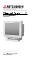
1
MITSUBISHI
AUTO-SCANNING WITH DIGITAL CONTROL
COLOR DISPLAY MONITOR
MODEL FFT9905SKHFW
USER'S GUIDE
For future reference, record the serial
number of your display monitor in the
space below:
SERIAL No.
The serial number is located on the
rear cover of the monitor.
CAUTION
The power cord provided with this monitor is designed for safety
and must be used with a properly grounded outlet to avoid possible
electrical shock.
Do not remove the monitor cabinet as this can expose you to very
high voltages and other hazards.
この装置は、情報処理装置等電波障害自主規制協議会(VCCI)の基準に基づく
第二種情報技術装置です。この装置は、家庭環境で使用することを目的としていますが、
この装置がラジオやテレビジョン受信機に近接して使用されると、受信障害を引き起こす
ことがあります。
取扱説明書に従って正しい取り扱いをしてください。
高調波ガイドライン適合品
Trademark
IBM, PC, PS/2, PS/V, Personal System/2 are registered trademarks of International Business
Machines Corp.
Apple Macintosh is a registered trademark of Apple Computer, Inc.
Quadra is a trademark of Apple Computer, Inc.
UNIX is a registered trademark in the United States and other countries, licensed exclusively through X/Open
Company Limited.
ENERGY STAR is a U.S. registered mark.
© 1998 MITSUBISHI ELECTRIC CORPORATION
RADIO INTERFERENCE REGULATIONS STATEMENT FOR U.S.A.
This equipment has been tested and found to comply with the limits for a Class B
digital device, pursuant to Part 15 of the FCC Rules. These limits are designed to
provide reasonable protection against harmful interference in a residential installation. This equipment generates, uses and can radiate radio frequency energy and,
if not installed and used in accordance with the instructions, may cause harmful
interference to radio communications. However, there is no guarantee that interference will not occur in a particular installation. If this equipment does cause harmful
interference to radio or television reception, which can be determined by turning the
equipment off and on, the user is encouraged to try to correct the interference by
one or more of the following measures:
- Reorient or relocate the receiving antenna.
- Increase the separation between the equipment and receiver.
- Connect the equipment into an outlet on a circuit different from that to which the
receiver is connected.
- Consult the dealer or an experienced radio/TV technician for help.
THIS PRODUCT HAS BEEN TESTED AND FOUND TO COMPLY
WITH THE LIMITS WITH SIGNAL CABLE SC-B102. USE IT TO
REDUCE THE POSSIBILITY OF CAUSING INTERFERENCE TO
RADIO, TELEVISION, AND OTHER ELECTRIC DEVICES.
NO USER SERVICEABLE PARTS INSIDE. DO NOT ATTEMPT TO
MODIFY THIS EQUIPMENT. IF MODIFIED, YOUR AUTHORITY TO
OPERATE THIS EQUIPMENT MIGHT BE VOIDED BY FCC.
WARNING!
This product is not designed for use in life support devices and Mitsubishi Electric
corporation makes no representations to the contrary. Life support devices are
those devices which are used to measure, diagnose, or evaluate the tissue, systems or functions of the human body; or other devices employed to support or
sustain life or good health.
MANUFACTURER DECLARATION FOR CE-MARKING:
We, Mitsubishi Electric Corp., declare under our sole responsibillity, that this
product is in conformity with the following standards:
EN60950
EN55022 Class B
EN50082-1
EN61000-3-2
EN61000-3-3
following the provisions of:
73/23/EEC Low Voltage Directive
89/336/EEC EMC Directive
As an ENERGY STAR Partner, Mitsubishi Electric Corporation has determined that
this product meets the ENERGY STAR guidelines for energy efficiency.
2
Congratulations! You have just purchased a TCO'95 approved and labelled product! Your
choice has provided you with a product developed for professional use. Your purchase has
also contributed to reducing the burden on the environment and to the further development
of environmentally-adapted electronic products.
Why do we have environmentally-labelled computers?
In many countries, environmental labelling has become an established method for
encouraging the adaptation of goods and services to the environment. The main problem
as far as computers and other electronic equipment are concerned is that environmentally
harmful substances are used both in the products and during their manufacture. Since it
has not been possible so far for the majority of electronic equipment to be recycled in a
satisfactory way, most of these potentially damaging substances sooner or later enter
Nature.
There are also other characteristics of a computer, such as energy consumption levels,
that are important from both the working and natural environment viewpoints. Since all
types of conventional electricity generation have a negative effect on the environment
(acidic and climate-influencing emissions, radioactive waste, etc.), it is vital to conserve
energy. Electronic equipment in offices consumes an enormous amount of energy, since it
is often routinely left running continuously.
What does labelling involve?
This product meets the requirements for the TCO'95 scheme, which provides for international
environmental labelling of personal computers. The labelling scheme was developed as a
joint effort by the TCO (The Swedish Confederation of Professional Employees),
Naturskyddsforeningen (The Swedish Society for Nature Conservation) and NUTEK (The
National Board for Industrial and Technical Development in Sweden).
The requirements cover a wide range of issues: environment, ergonomics, usability, emission
of electrical and magnetic fields, energy consumption and electrical and fire safety.
The environmental demands concern among other things restrictions on the presence
and use of heavy metals, brominated and chlorinated flame retardants, CFCs (freons),
and chlorinated solvents. The product must be prepared for recycling and the manufacturer
is obliged to have an environmental plan, which must be adhered to in each country where
the company implements its operational policy.
The energy requirements include a demand that the computer and/or display after a certain
period of inactivity shall reduce its power consumption to a lower level, in one or more
stages. The length of time to reactivate the computer shall be reasonable for the user.
Labelled products must meet strict environmental demands, for example in respect of the
reduction of electric and magnetic fields, along with physical and visual ergonomics and
good usability.
3
In and after the middle of this page, you will find a brief summary of the environmental
requirements met by this product. The complete environmental criteria document may be
ordered from:
TCO Development Unit
S-114 94 Stockholm
Sweden
Fax: +46 8 782 92 07
E-mail (Internet): [email protected]
Current information regarding TCO'95 approved and labelled products may also be
obtained via the Internet, using the address:
http//www.tco-info.com/
TCO'95 is a co-operative project between
Environmental Requirements
Brominated flame retardants are present in printed circuit boards, cabling, casings and
housings, and are added to delay the spread of fire. Up to 30 % of the plastic in a computer
casing can consist of flame-retardant substances. These are related to another group of
environmental toxins, PCB, and are suspected of giving rise to similar harm, including reproductive damage in fish-eating birds and mammals. Flame retardants have been found in
human blood and researchers fear that they can disturb foetus development.
Bio-accumulative* TCO'95 demands require that plastic components weighing more than 25
grammes must not contain frame retardants with organically bound chlorine or bromine.
Lead
can be found in picture tubes, display screens, solder and capacitors. Lead damages the
nervous system and in higher doses, causes lead poisoning.
The relevant bio-accumulative* TCO'95 requirement permits the inclusion of lead, as no
replacement has yet been developed.
Cadmium
is present in rechargeable batteries and in the colour-generating layers of certain computer
displays. Cadmium damages the nervous system and is toxic in high doses.
The relevant bio-accumulative* TCO'95 requirement states that batteries may not contain
more than 25 ppm (parts per million) of cadmium. The colour-generating layers of display
screens must not contain any cadmium.
Mercury
is sometimes found in batteries, relays and switches. Mercury damages the nervous system
and is toxic in high doses. The relevant bio-accumulative* TCO'95 requirement states that
batteries may no contain more than 25 ppm (part per million) of mercury.
demands require that no mercury is present in any of the electrical or electronic components
concerned with the display unit.
CFCs (freons) are sometimes used for washing printed circuit boards and in the
manufacture of expanded foam for packaging. CFCs break down ozone and thereby damage
the ozone layer in the stratosphere, causing increased reception on Earth of ultra-violet
light with consequent increased risks of skin cancer (malignant melanoma).
The relevant TCO'95 requirement: Neither CFCs nor HCFCs may be used during
manufacture of the product or its packaging.
* Bio-accumulative is defined as substances which accumulate within living organisms.
4
Diamond Scan 90e
User’s Guide
CONTENTS
1. INTRODUCTION ..................................................................................................
1.1 Features .....................................................................................................
1.2 Internal Preset Memory Capability .............................................................
1.3 Power Management Function ....................................................................
1.4 DDC ...........................................................................................................
1.5 Location Considerations ............................................................................
1.6 Cleaning Your Monitor ...............................................................................
1.7 Unpacking ..................................................................................................
1.8 Tilt/Swivel Base .........................................................................................
Screen Position Adjustment .......................................................................
1.9 Quick Operation Chart ...............................................................................
6
6
7
7
8
8
8
9
9
9
10
2. CONNECTING THE MONITOR ...........................................................................
2.1 AC Power Connection ...............................................................................
2.2 Signal Cable Connection ...........................................................................
2.2.1 Connecting to Any IBM VGA Compatible System ..............................
2.2.2 Connecting to An Apple Macintosh Centris, Quadra, and
Apple Macintosh II Family ..................................................................
2.2.3 Connecting to a Unix Workstation & Third Party Graphics Card ........
11
11
11
11
12
12
3. USER CONTROLS ............................................................................................. 14
3.1 Control Names ........................................................................................... 14
3.2 Function ..................................................................................................... 14
4. OSD(On Screen Display) FUNCTIONS ............................................................... 16
4.1 Operation ................................................................................................... 17
4.2 POWER SAVE ........................................................................................... 23
5. TROUBLESHOOTING ......................................................................................... 24
6. SPECIFICATIONS ............................................................................................... 25
7. APPENDIX ...........................................................................................................
7.1 Monitor Signal Input Connector (DB9-15P) ...............................................
7.2 Serial Interface Input Connector (DIN-8P) For Serial Interface Function ..
7.3 SC-B102 Signal Cable ...............................................................................
7.4 Macintosh Adapter AD-A205 settings ........................................................
26
26
26
27
28
Note : This manual is designed for use with Diamond Scan 90e color display monitor.
5
1
INTRODUCTION
Congratulations on your purchase of the Diamond Scan 90e high resolution color monitor. Mitsubishi
designed this monitor to provide you with years of reliable trouble-free operation. Once again, thank
you for selecting our product and welcome to Mitsubishi!
This guide tells you how to connect, adjust and care for your Diamond Scan 90e monitor. This guide
also provides technical specifications and instructions for troubleshooting any basic problems you
may experience with your monitor.
1.1
Features
The Diamond Scan 90e is a 49.5cm/19"(46cm/18.0" Diagonal Viewable Image) intelligent, microprocessor-based monitor compatible with most analog RGB (Red, Green, Blue) display standards,
including PS/V®, PS/2®, Apple® Macintosh® Centris, Quadra, and Macintosh II family signals.
It provides crisp text and vivid color graphics with VGA, SVGA, XGA (non-interlaced), and most
Macintosh compatible color video cards.
• The monitor’s wide auto-scanning compatibility range makes it possible to upgrade video cards or
software without purchasing a new monitor.
• Digitally controlled auto-scanning is done using an internal microprocessor, for horizontal scan
frequencies between 30kHz and 95kHz, and vertical scan frequencies between 50Hz and 152Hz.
The microprocessor-based intelligence allows the monitor to operate in each frequency mode with
the precision of a fixed frequency monitor.
• The monitor contains resident memory for pre-programmed screen display standards and is also
capable of storing additional user adjustment parameters.
• The monitor is capable of producing a maximum horizontal resolution of 1600 dots and a maximum
vertical resolution of 1200 lines typically. This display is well suited for windowing environments.
• Because of the analog signal inputs, the monitor can display an unlimited palette of colors that can
be manually adjusted to suit your specific needs.
• The monitor has a power management function accorded to VESA-DPMS-standard. To save
energy, the monitor must be connected to a system compliant with the VESA DPMS-standard.
(Refer to your computer and/or video card instructions for proper operation.)
• To ensure ease of installation and ongoing use, the monitor features Moire Clear Function and OnScreen Display (OSD) of all monitor set-up and adjustment functions.
• For use in a variety of applications, the monitor complies with UL 1950, CSA C22.2 No.950 and
EN60950 for safety, FCC Class-B, VCCI Class II and EN55022 Class-B for EMI, MPR-II, ISO 92413 and ISO 9241-8 for ergonomics. The monitor also complies with TCO'95 guideline for
environmental safe use.
• Digital Chassis design for lighter, more compact enclosure and increased screen performance.
• Short neck (ZENTAN) CRT with 0.25mm pitch shadow mask, advanced-focus DQ-DAF (Double
Quadrupole-Dynamic Astigmatism and Focus system) electron gun and high contrast opticalquality coating.
TM
• The monitor complies with Video Electronics Standards Association (VESA ) DDC1/2B(EDID)
specification. If your computer provides DDC1/2B(EDID) function, setup will be done automatically.
• USB-HUB unit KT-X406 is prepared as an optional parts for this monitor.
6
1.2
Internal Preset Memory Capability
To minimize adjustment needs, the factory has preset popular display standards into the monitor,
as shown in Table 1. If any of these display standards are detected, the picture size and centering are automatically adjusted. All of the factory presets may be overwritten by adjusting the user
controls. The monitor is capable of automatically storing up to 6 additional display standards.
The new display information must differ from any of the existing display standards by at least
1kHz for the horizontal scan frequency or 5Hz for the vertical scan frequency or the sync signal
polarities must be different.
Table 1. Memory Buffer Factory Presets
Polarity
640
1024
1280
1.3
Resolution
x 480
x 768
x 1024
N.I.
N.I.
N.I.
Fh (kHz)
31.5
60.0
80.0
Fv (Hz)
60.0
75.0
75.0
H
+
+
V
+
+
Power Management Function
The monitor has the power management function which reduces the power consumption of the
monitor when not in use. There are three reduced power level modes.
Stand-by mode
When the horizontal sync signal is off after about 10 seconds, the monitor is switched to a
stand-by mode. When the monitor is in stand-by mode, the screen is off.
After the horizontal sync signal is restored, picture will be displayed immediately.
Suspend mode
When the vertical sync signal is off, after about 10 seconds the monitor is switched to a
suspend mode which reduces the monitor power consumption to less than 15W.
When the monitor is in suspend mode, the screen is off and the power indicator will change to
amber. After the vertical sync signal is restored, picture will be displayed within a few seconds.
Power-off mode
When the horizontal sync signal and vertical sync signal are off, after about 10 seconds the
monitor is switched to a power-off mode, which reduces the monitor power consumption to
less than the power consumed at suspend mode above.
When the monitor is in power-off mode, the screen is off, and the power indicator will change
to amber.
After both the sync signals are restored, picture will be displayed within several seconds.
7
1.4
DDC
The monitor includes the DDC1 and DDC2B feature. DDC (Display Data Channel) is a communication channel over which the monitor automatically informs the host system about its capabilities
(e.g. each supported resolution with its corresponding timing).
DDC is routed through previously unused pins of the 15-pin VGA connector.
The system will perform "Plug and Play" feature if both, monitor and host, implement the DDC
protocol.
1.5
Location Considerations
When setting up and using the monitor, keep the following in mind:
*
For optimum viewing, avoid placing the monitor against a bright background or where sunlight
or other light sources may reflect on the display area of the monitor; place the monitor just
below eye level.
*
Place the monitor away from strong magnetic or electromagnetic fields, such as
high capacity transformers, electric motors, large current power lines, steel pillars,
etc.... Magnetism can cause distortion in the picture and/or color purity.
*
Avoid covering the slots or openings of the monitor. Allow adequate ventilation
around the monitor so the heat from the monitor can properly dissipate. Avoid putting the
monitor into any enclosure that does not have adequate ventilation.
*
Avoid exposing the monitor to rain, excessive moisture, or dust, as this can
cause a fire or shock hazard.
*
Avoid placing the monitor, or any other heavy object, on the power cord.
Damage to the power cord can cause a fire or electrical shock.
*
When transporting the monitor, handle it with care.
CAUTION
Keep your fingers away from the pivot area of the tilt/swivel base.
1.6
Cleaning Your Monitor
When cleaning the monitor, please follow these guidelines:
*
*
*
Always unplug the monitor before cleaning.
Wipe the screen and cabinet front and sides with a soft cloth.
If the screen requires more than dusting, apply a household window cleaner to a soft cloth to
clean the monitor screen.
CAUTION
Do not use benzene, thinner or any volatile substances to clean the unit as the finish may be
permanently marked. Never leave the monitor in contact with rubber or vinyl for an extended time
period.
8
1.7
Unpacking
After you unpack the box you should have all of the items indicated in Figure 1. Save the box
and packing materials in case you ship or transport the monitor. Complete and mail in warranty
cards.
1
4
3
2
N
1
5
20
-A
AD
O
2
3
M
4
IT
5
SU
BI
6
SH
I
1. Diamond Scan 90e Color Monitor
2. AC Power Cord
3. Signal Cable SC-B102
4. Macintosh Adapter AD-A205
5. User’s Guide
6. Warranty-Set
6
5
M
o
m ide
u
ia
D r's G
O
DE
L
e
s
U
AU
CO TO
LO -TR
R AC
DI
SP KI
LA NG
Y WI
MO TH
NI DI
TO GI
R TA
L
I
e
H
0
9
IS
n
B
a
U
c
S
S
d
IT
n
M
FF
T99
05
SK
HK
W
CO
NT
RO
L
Figure 1.
1.8
Tilt/Swivel Base
The monitor comes with a tilt/swivel base. This enables you to position the monitor to the best
angle and tilt for maximum viewing comfort.
Screen Position Adjustment
Adjust the tilt and rotation of the monitor by placing your hands at opposite sides of the case, as
shown in Figure 2. You can adjust the monitor 45 degrees right or left, 10 degrees up or 5
degrees down, as shown below.
10
45
45
5
Figure 2.
9
1.9 Quick Operation Chart
To summarize the steps in connecting your computer and adapter with Diamond Scan 90e color
monitor and setting the necessary controls and switches, refer to the chart below.
Connect the power cord to the Diamond Scan 90e color
monitor and the signal cable between the Diamond
Scan 90e and the graphics adapter.
See 2.1 AC Power Connection
2.2 Signal Cable Connection
Turn on the computer.
Turn on the Diamond Scan 90e color monitor.
See 3. USER CONTROLS
4. FUNCTION CONTROLS
Set the controls and switches.
If a problem appears.
OK
OK
See 5. TROUBLESHOOTING
If the problem persists.
Call for your authorized MITSUBISHI
Product Support at 1-800-344-6352.
10
2
CONNECTING THE MONITOR
On the back of the monitor are four plug-in connections: one for the AC power cord, DB9-15P
connector, BNC connector for video and a DIN-8P connector for the optional USB-unit.
2.1
AC Power Connection
One end of the AC power cord is connected into the AC power connector on the back of the
monitor. The other end is plugged into a properly grounded three-prong AC outlet. The
monitor’s auto-sensing power supply can automatically respond to the power supply input of 100240V AC and 50/60Hz.
2.2
Signal Cable Connection
The attached video signal cable provides a DB9-15P connector for the VGA compatible analog
RGB outputs on your computer. The RGB signal may be derived from an IBM® PS/2, or compatible Apple Macintosh built-in video. Most third party color cards can also be interfaced using the
free Mitsubishi Apple adaptor available from your dealer.
2.2.1 Connecting to Any IBM VGA Compatible System
Figure 3 shows the SC-B102 cable connection to the Video Graphics Array (VGA) port in an IBM
Personal System/2® Model 50, 60, 70 and 80, or any VGA compatible system.
1.
2.
3.
4.
5.
Power off, the monitor and the computer.
Connect the one end of the SC-B102 cable to the DB9-15P connector on the VGA
controller card.
Connect the other end of the SC-B102 cable to the DB9-15P receptacle on the back of
the monitor.
Power on the computer, then the monitor.
After using the system, power off the monitor, then the computer.
Computer
VGA
Compatible
System
D-SUB
R
Serial
G
B
COMP.
HD
VD
DB9-15P
DB9-15P
Power Cord
CABLE SC-B102
Figure 3.
CAUTION
The socket-outlet shall be installed near the equipment and shall be easily accessible. During
servicing, disconnect the plug from the socket-outlet.
Méme si le moniteur est mis hors tension il reste toujours alimenté. La prise secteur devrait
ainsi ètre facilement accssible en cas d'urgence.
11
2.2.2 Connecting to An Apple Macintosh Centris, Quadra, and Apple Macintosh II Family
Figure 4 shows the SC-B102 cable and AD-A205 Adapter to the video port in an Apple Macintosh.
1.
2.
3.
4.
5.
6.
7.
Power off, both the monitor and the computer.
Set the DIP switches of Macintosh Adapter according to the setting chart.
(See 7.4 Macintosh Adapter AD-A205 settings)
Connect the 15-pin (DB-15P) end of the AD-A205 Adapter to the straight 15-pin connector on
the Macintosh video port on the CPU or on the video board.
Connect the sub-miniature 15-pin (DB9-15P) end of AD-A205 Adapter to the SC-B102 cable.
Connect the other end of the SC-B102 cable to the DB9-15P receptacle on the back of the
monitor.
Power on the Macintosh, then the monitor.
After using the system, power off the monitor, then the Macintosh.
Apple
Macintosh
Computer
Macintosh
DB-15P
Adapter
DB9-15P
AD-A205
D-SUB
R
G
B
Serial
COMP.
HD
VD
DB9-15P
Power Cord
CABLE SC-B102
Please see APPENDIX (7.4 Macintosh Adapter AD-A205 settings).
Figure 4.
2.2.3 Connecting to a Unix Workstation & Third Party Graphics Card
Figure 5 shows the SC-B102 or “75 ” coaxial cable (not supplied) connection to the graphics
video card (PC-CAD and workstation).
1.
2.
3.
4.
5.
Power off, both the monitor and the computer.
Connect one end of the SC-B102 cable or the “75 ” coaxial cable to the output connector on
the CPU, or on the video board.
Connect the other end of the SC-B102 cable or the “75 ” coaxial cable to the DB9-15P
receptacle or the BNC receptacles on the back of the monitor.
Power on the computer, then the monitor.
After using the system, power off the monitor, then the computer.
High Resolution
Graphic Video Card
D-SUB
R
Serial
G
B
COMP.
HD
High Resolution
Graphic Video Card
VD
“75Ω” coaxial cable
Power Cord
Please see next page about BNC connection.
DB9-15P
Cable SC-B102
Figure 5.
12
BNC CONNECTION
(1) IN CASE OF A COMPOSITE SYNC ON GREEN VIDEO SIGNAL (SYNC ON GREEN):
Connect the R, G and B video signals to the BNC receptacles on the back of the monitor.
D-SUB
R
G
B
COMP.
HD
VD
Serial
(2) IN CASE OF EXTERNAL COMPOSITE SYNC SIGNAL:
Connect the R, G and B video signals and the Composite sync signal to BNC receptacles on
rear panel, respectively.
D-SUB
R
G
B
COMP.
HD
VD
Serial
(3) IN CASE OF SEPARATE HORIZONTAL AND VERTICAL SYNC SIGNALS:
Connect the R, G and B video signals and the horizontal and vertical sync signals to the BNC
receptacles on the rear panel.
D-SUB
R
Serial
13
G
B
COMP.
HD
VD
3
USER CONTROLS
3.1
Control Names
See Figure 6 and 7 for the location of the following user controls and indicators.
Each control is identified by number and is described individually on page 14.
[How to use the front control panel]
” on
Press the button marked “
the control panel to open.To close,
press it again.
FRONT
1. POWER SWITCH
2. POWER-ON INDICATOR
4. OSD OFF BUTTON
BNC/D-SUB
6. FUNCTION ADJUST BUTTONS
OFF
ADJUST
DEGAUSS
SELECT
3. INPUT CONNECTOR SELECT BUTTON
7. DEGAUSS BUTTON
5. FUNCTION SELECT BUTTONS
Figure 6
3.2
Function
1.
POWER SWITCH: A push-on push-off switch for AC power.
2.
POWER-ON INDICATOR: This indicator illuminates Green when AC power is on or Standby mode, and illuminates Amber when suspend or power-off mode.
3.
INPUT CONNECTOR SELECT BUTTON: Push the BNC/D-SUB button to select the input
signal BNC or D-SUB.
4.
OSD OFF BUTTON: A push type button that is used to turn off the OSD.
5.
FUNCTION SELECT BUTTONS: Push the select buttons to choose one of the functions that
is superimposed on the display screen.
6.
FUNCTION ADJUST BUTTONS: Push the adjust buttons to adjust the image on the screen
that is selected via the function select buttons.
7.
DEGAUSS BUTTON: A push type button that is used to eliminate possible color shading or
impurity.
14
REAR
D-SUB
R
G
B
Serial
COMP.
HD
VD
SIGNAL INPUT CONNECTOR
(DB9-15P)
AC POWER CONNECTOR
9. DC POWER OUTPUT CONNECTOR
D-SUB
R
G
B
COMP.
HD
VD
Serial
8. SERIAL INTERFACE CONNECTOR
(DIN-8P)
SIGNAL INPUT CONNECTOR (BNC)
Figure 7
8.
SERIAL INTERFACE CONNECTOR: The monitor has a DIN-8P connector for serial
interface communication. This connector will be used for optional USB unit. For the
information about connecting, please refer to the instruction which is included in each
optional kit.
For further information about the optional USB kit, please contact your authorized
MITSUBISHI dealer.
9.
DC POWER OUTPUT CONNECTOR:
CAUTION Do not connect the DC power connector with any models except MITSUBISHI
USB unit.
15
4
OSD(On Screen Display) FUNCTIONS
(1)
(2)
(3)
(4)
CONTRAST:
Adjusts to the desired contrast level.
BRIGHTNESS: Adjusts to the black level of the screen.
COLOR-TEMPERATURE: Adjusts the color temperature of the screen image.
INFORMATION: Indicate current Scanning frequency and input Video signal port
(signal connector)
(5) H-SIZE (Horizontal Size): Controls the horizontal size of the image on the screen.
(6) H-PHASE (Horizontal Position): Controls the horizontal position of the image on the screen.
(7) V-SIZE (Vertical Size): Controls the vertical size of the image on the screen.
(8) V-POSITION (Vertical Position): Controls the vertical position of the image on the screen.
(9) SIDE-BOW (Pincushion or Bow Amplitude): Straightens the left and right sides of the screen
image.
(10) KEY STONE:
Adjusts the parallelism of the left and right sides of the screen image.
(11) PIN-BALANCE: Adjusts the curvature of the left and right sides of the screen image.
(12) KEY-BALANCE: Adjusts the vertical slant or tilt of the screen image.
(13) H-MOIRE:
Adjusts the horizontal moire level on the screen.
(14) V-MOIRE:
Adjusts the vertical moire level on the screen.
(15) ROTATION:
Adjusts the rotation or twist of the picture.
(16) GEOMETRY-RESET: Restore to factory preset following mode; H-SIZE, H-PHASE, V-SIZE, VPOSI, SIDE-BOW, KEY STONE, PIN-BALANCE, KEY-BALANCE.
(17) POWER-SAVE (ON/OFF): When adjusting ON, reduces the power consumption of the monitor when not
in use.
(18) VIDEO LEVEL: Selects video levels 1.0V or 0.7V.
(19) CLAMP-POSITION: Use this function to eliminate excessive green or white background that may
occur when both Sync-On-Green and external sync signals are applied to the
monitor.
(20) USB PORT SELECT: Control upstream connection with using optional USB unit KT-X406.
16
4.1
Operation
Press any select button and control indicators will be superimposed on the display screen called
1st layer.
Refer to Figure 6 for the location of the monitor function (
) controls. Press the
select buttons to choose one of the following controls.
The indication of a function symbol changes to blue.
When selected the function symbol of above OSD, press the adjust button (
or
), the OSD
screen changes to following called 2nd layer. Then you can adjust each function by
buttons.
SELECT
1st OSD layer
z
z z
Push any button
USB
VIDEO
CLAMP
CONT R AS T
Push any button
LED : Stand-by, Normal : Green
Suspend, Power-off : Amber
2nd OSD layer
CON T R A S T
9 0%
Push any button
Push
button to
increase contrast.
Push
button to
decrease contrast.
17
2
10 6
14 15
3
7 11
1
4
5
8
9
12
16
13
z
17
USB
z z
CLAMP
VIDEO
20
CONT R AS T
18
Symbol of 1st
OSD layer
19
Press the Minus Adjust Button:
Press the Plus Adjust Button:
2nd OSD layer
1 CONTRAST
CON T R A S T
9 0%
LEVEL: 00 - 100%
To increase the contrast.
To decrease the contrast.
Press plus and minus buttons together, to restore
to factory preset level.
2 BRIGHTNESS
BR I GH T N E S S
9 0%
To decrease the brightness.
To increase the brightness.
Press plus and minus buttons together, to restore
to factory preset level.
LEVEL: 00 - 100%
3 COLOR TEMPERATURE
To increase the red color
level.
CO L OR - T EM P ER AT U RE
930 0 K
To increase the blue color
level.
Data indicates color temperature
(k:kelvin)
LEVEL: 5000 - 9950K
4 INFORMATION
6 9 . 0 KH Z @ 7 5 H Z
CONN E C T OR D - S UB
R
G
• Indicate the horizontal frequency and the vertical
frequency of input signal.
• Indicate input connector.
B
18
Symbol of 1st
OSD layer
Press the Minus Adjust Button:
Press the Plus Adjust Button:
To narrow the width of
the image on the screen.
To expand the width of
the image on the screen.
To move the image to
the left.
To move the image to
the right.
2nd OSD layer
5 H-SIZE
H-S IZE
9 0%
LEVEL: 00 - 100%
6 H-PHASE
H - PHASE
9 0%
LEVEL: 00 - 100%
7 V-SIZE
V- S I ZE
9 0%
LEVEL: 00 - 100%
To narrow the height of
the image on the screen.
To expand the height of
the image on the screen.
To move the image down.
To move the image up.
To collapse the center of
the image.
To expand the center of
the image.
8 V-POSITION
V - P OS I T I ON
9 0%
LEVEL: 00 - 100%
9 SIDE-BOW
S I D E - BOW
9 0%
LEVEL: 00 - 100%
19
Symbol of 1st
OSD layer
10
Press the Minus Adjust Button:
Press the Plus Adjust Button:
The decrease the width at
the top of the screen image
and to increase the width at
the bottom.
The increase the width at
the top of the screen image
and to decrease the width
at the bottom.
2nd OSD layer
KEYSTONE
KE Y S T ONE
9 0%
LEVEL: 00 - 100%
11
PIN-BALANCE
P I N - B AL A NCE
9 0%
LEVEL: 00 - 100%
12
To move the top and
bottom of the screen
image to the right.
To move the top and
bottom of the screen
image to the left.
KEY-BALANCE
KE Y - B AL A NCE
9 0%
LEVEL: 00 - 100%
13
To make the screen slant
to the left.
To make the screen slant
to the right.
H-MOIRE
Press the plus or minus button to decrease the
level of the horizontal moire wave.
H - MO I RE
9 0%
Press plus and minus buttons together, to restore
to factory preset level.
LEVEL: 00 - 100%
14
V-MOIRE
Press the plus or minus button to decrease the
level of the vertical moire wave.
V - MO I RE
9 0%
Press plus and minus buttons together, to restore
to factory preset level.
LEVEL: 00 - 100%
20
Press the Minus Adjust Button:
Symbol of 1st
OSD layer
15
Press the Plus Adjust Button:
2nd OSD layer
ROTATION
RO T A T I ON
9 0%
To rotate to the left.
LEVEL: 00 - 100%
16
To rorate to the right.
Press plus and minus buttons together, to restore
to factory preset level.
GEOMETRY RESET
To cancel the geometry
reset operation.
GEOME T R Y - R E S E T
C A NC E L
PROCEED
To reset the geometry
data to factory adjusted
condition.
MEMORY
17
POWER-SAVE
To select the constant
power-on mode.
z
z z
POWER - S A V E
OF F
ON
POWER - S A V E
OF F
ON
VIDEO-LEVEL
To select 1.0V of video
input.
VIDEO
To select 0.7V of
video input.
V I D EO - L E V E L
1 . 0V
0 . 7V
V I D EO - L E V E L
1 . 0V
0 . 7V
19
To select the
power-save mode.
ON
POWER - S A V E
OF F
18
R ES E T
V I D EO - L E V E L
1 . 0V
0 . 7V
CLAMP-POSITION
CLAMP
CL AMP - P OS I T I ON
F R ON T
BACK
To clamp the video
signal at the front of
the H-Sync pulse.
CL AMP - P OS I T I ON
F R ON T
BACK
21
To clamp the video
signal at the back of
the H-Sync pulse.
CL AMP - P OS I T I ON
F R ON T
BACK
Press the Minus Adjust Button:
Symbol of 1st
OSD layer
20
USB PORT SELECT
USB
21
Press the Plus Adjust Button:
2nd OSD layer
USB S T A T US
P L E A S E C H E CK
MO N I T OR
CO N NE C T I ON OR
USB IS S US P E NDED
This "USB PORT SELECT" is prepared for optional
part "USB-unit KT-X406" installed only.
Attention OSD screen is displayed without USB unit.
For installing USB-unit, please read the manual of
USB kit.
ADJUST LOCK
1. Press the right of select button and minus of adjust button together, the "ADJUST LOCK"
screen appears.
SELECT
AD J US T M E N T - L OCK
E NABL E
D I S AB L E
2.
Press the plus button to lock on the OSD, and "LOCKED" character is indicated on 1st layer.
You can operate OSD menu only CONTRAST, BRIGHTNESS and INFORMATION.
( LO C K E D )
3.
Press the minus button to lock off the OSD. You can operate OSD and all can be selected
menu again.
22
4.2
POWER SAVE
NOTE
When the monitor has no sync signal or incorrect connection and the signal frequency is out of
range, the following CAUTION comes on the screen. Check input signal, signal cable connection
and signal frequency.
1. POWER SAVE IS OFF
When POWER SAVE is OFF and there is no sync signal, the following screen is displayed.
AT T E N T I ON
NO S I GNAL
P L E A S E C H E CK
I N P U T S I GNAL OR
CO N NE C T I ON .
2. POWER SAVE IS ON
(1) When POWER SAVE is ON and there is
no sync signal, the following screen is
displayed for 5 seconds.
(2) Before 2 seconds POWER SAVE function
works, the following screen is displayed.
The power on indicator illuminates to
change Amber.
AT T E N T I ON
NO S I GNAL
P L E A S E C H E CK
I N P U T S I GNAL OR
CO N NE C T I ON .
POWER S A V E
3. POWER SAVE IS ON OR OFF
When signal frequency is out of range, the following screen(ex. 96.8kHz/73Hz timing
input) is displayed.
AT T E N T I ON
S I GNAL F RE QUENCY
I S OU T OF RANGE .
P L E A S E C H ANGE
S I GNAL T I M I NG .
23
5
TROUBLESHOOTING
Before calling your Authorized Product Support, please check that the items below are properly
connected or set.
In case of using a non-standard signal, please check the pin assignments and the signal timing of your
computer with the specification outlined in SPECIFICATION 6 and APPENDIX 7.
ITEMS TO CHECK
PROBLEM
No
picture
• Front (Adjust to the
maximum brightness or
push the reset button)
• Front
Power switch.
• Rear
AC power cord disconnected.
• Rear
Signal cable disconnected.
• Check the graphics
BNC cables are misconnected or the green
adapter and cables
cable is disconnected.
• Computer
Computer power switch.
• Check the power managePower management function is active.
ment function. (see P23)
• Rear
BNC cables are misconnected.
Input signal frequency range is disagreement. • Check the specification of
graphics adapter and
CGA MODE is not available.
monitor
MDA MODE is not available.
EGA MODE is not available.
• Rear
BNC cables are misconnected.
(Green and composite sync. connection is
reversed)
• Front (OSD)
Adjust H.SIZE, V.SIZE, H.PHASE, and
V.POSITION with non-standard signals
• Front (OSD)
Monitor may not be able to get full-screen image
depend on signal. In this case, please select other
resolution, or other vertical refresh timing.
Make sure you wait a few seconds after adjusting
the size of the image before changing or disconnecting the signal or powering OFF the monitor.
LED
On-Green
• Contrast and brightness controls.
LED
Off
•
•
•
•
LED
On-Amber
•
•
•
Un-stable •
picture
Abnormal
picture
No green
color with
BNC
•
•
•
Display is missing,
center shifts, or
too small or too
•
large of a display
size
Display is not stable
Display is dark
or too bright
LOCATION
• Rear
• BNC cables are misconnected.
• Front (OSD)
• Input video signal level select is not at the
appropriate position for your graphics adapter
output.(0.7V or 1.0Vp-p)
24
6
SPECIFICATIONS
Size
Mask type
Gun
Deflection angle
Phosphors
49.5cm/19" (46cm/18" Diagonal Viewable Image)
Shadow Mask
In-line
100°
CRT
Red, Green, Blue EBU
(medium short persistence) Crystal pigment
Dot pitch
0.25mm
Face Plate
Anti-glare, Anti-reflection and Anti-static coating
Focusing method
Double Quadrupole-Dynamic Astigmatism
and Focus system (DQ-DAF)
INPUT SIGNAL
Video
0.7 and 1.0Vp-p analog RGB
Sync
Sync. on Green or separated H, V
sync. or Composite sync
INTERFACE
Input Connector
5BNC, DB9-15P, DIN-8P(for USB kit)
Input Impedance
75Ω (video), 1kΩ (sync)
SCANNING
Horizontal
30 - 95kHz
FREQUENCY
Vertical
50 - 152Hz
RESOLUTION (HxV) 1600dots x 1200lines Non-Interlaced maximum addressable resolution format at 75Hz
WARM-UP TIME
30 minutes to reach optimum performance level
BRIGHTNESS
VIDEO AMPLIFIER
BLANKING TIME
DISPLAY SIZE
COLOR
POWER SOURCE
OPERATING
ENVIRONMENT
CABINET
WEIGHT
TILT/SWIVEL
BASE
REGULATIONS
≧100cd/m2, standard full white video signal at 9300K + 8MPCD
50Hz - 150MHz (typ.)
Horizontal
≧2.3 µsec (typ.)
Vertical
≧500 µsec (typ.)
340mm x 255mm (typ.)
ratio 4:3, e.g. 1600dots x 1200lines
5000 ~ 9950K
100-240VAC ±10% 50/60Hz 150W (typ.)
< 130W (typ.: without USB-Unit KT-X406) >
Temperature
5 - 35°C
Humidity
10 - 90%RH (without condensation)
(W)18.5inch x (H)18.5inch x (D)16.1inch
(W)470mm x (H)468mm x (D)408 mm
22.5kg (49.6lbs.)
Tilt Angle
-5° - +10°
Swivel Angle
±45°
Safety
UL1950 (UL), CSA C22.2 No.950 (C-UL)
EN60950 (TÜV-GS)
EMC
FCC Class-B, DOC Class-B
EN55022 Class-B, VCCI Class-2
EN50082-1, EN61000-3-2, EN61000-3-3
X-Ray
DHHS, HWC
Röv vom 8.1, 1987
Other
CE-Marking, MPR-II
ISO 9241-3, ISO 9241-8 (TÜV-ERGO)
TCO '95
ZH1/618 (TÜV-GS)
International Energy Star Program
Guidelines for the Suppression of Harmonics
in Appliances and General-Use Equipment
25
7
7.1
APPENDIX
Monitor Signal Input Connector (DB9-15P)
Pin No.
1
2
(Female)
5
DB9-15P
4
14
15
2
3
9
10
12
13
1
7
8
6
11
MOUNTED ON THE REAR PANEL
DDC .............
SDA ..............
SCL ..............
NC ................
7.2
DISPLAY DATA CHANNEL
SERIAL DATA
SERIAL CLOCK
NO-CONNECTION
3
4
5
6
7
8
9
10
11
12
13
14
15
PIN ASSIGNMENT
Signal
RED VIDEO
GREEN VIDEO
or COMPOSITE SYNC with GREEN VIDEO
BLUE VIDEO
GROUND
DDC GROUND
RED GROUND
GREEN GROUND
BLUE GROUND
NC
SYNC GROUND
GROUND
SDA
HORIZONTAL SYNC
or COMPOSITE SYNC
VERTICAL SYNC(VCLK)
SCL
Serial Interface Input Connector (DIN-8P) For Serial Interface Function
PIN ASSIGNMENT
(Female)
Pin No.
Signal
1
DTR (Data Terminal Ready)
2
NC
3
TXD (Transmited Data)
4
GND
5
RXD (Receive Data)
6
GND
7
NC
8
NC
7
DIN-8P
8
6
3
4
5
2
1
MOUNTED ON THE REAR PANEL
NC......................... NO-CONNECTION
26
7.3
SC-B102 Signal Cable
PIN ASSIGNMENT AND SIGNAL LEVEL
Approx. 1.8m
2
1
6
11
DB9-15P
(Male)
DB9-15P
(Male)
Wire : 5 coaxial
SIGNAL
ANALOG
PIN
ASSIGNMENT
1
2
3
4
5
6
7
8
9
10
11
12
13
14
15
RED
GREEN
BLUE
GROUND
DDC GROUND
RED GROUND
GREEN GROUND
BLUE GROUND
NC
SYNC GROUND
GROUND
SDA
HORIZONTAL SYNC
VERTICAL SYNC(VCLK)
SCL
SIGNAL LEVEL
NC ..................... NO-CONNECTION
DDC: DISPLAY DATA CHANNEL
SDA: SERIAL DATA
SCL: SERIAL CLOCK
27
3
12
13
5
4
9
8
7
10
14
15
7.4
Macintosh Adapter AD-A205 settings
The AD-A205 Macintosh Adapter allows you to take advantage of the built-in video capabilities
of your Macintosh computer with the monitor.
With it, you may select any available video mode via the DIP Switches.
Using the following chart, find the computer/resolution combination you wish to configure.
There are alternate settings available for most computer / resolution combinations, but we
recommend you set the factory preset timing. (see 1.2 Internal Preset Memory Capability)
The chart shows all available modes for Macintosh systems plus all possible combinations with
monitor. Please be aware that not all Macintosh modes are capable of driving all Macintosh
video modes.
Macintosh
DIP Switches
AD
20
N
O
-A
5
1
2
5
4
I
3
SH
BI
SU
IT
M
6
ON
Display Monitor
F
OF
In case of the computer corresponding to Multimode, you can select the resolution on your
computer by setting the following switch.
Please refer to instruction book of your computer about resolution setting.
21"Multimode
1,2,6 = Set DIP switches 1,2 and 6 "ON" (Supports 640X480@67Hz; 832X624@75Hz;
1024X768@75Hz; 1152X870@75Hz) or (Supports 640X480@67Hz;
832X624@75Hz; 1024X768@75Hz;
1152X870@75Hz; 1280X1024@75Hz ) or
(Supports 640X480@67Hz; 832X624@75Hz;
1024X768@75Hz;
1152X870@75Hz; 1280X960@75Hz; 1280X1024@75Hz)
17"Multimode
1,2,5 = Set DIP switches 1,2 and 5 "ON" (Supports 640X480@67Hz; 832X624@75Hz;
1024X768@75Hz)
13"Multimode
1,2,5,6 =
Set DIP switches 1,2,5 and 6 "ON" (Supports 640X480@67Hz;
832X624@75Hz)
28
AD-A205 Mac Adapter settings Chart
Apple
Apple
Power
Macintosh Macintosh Macintosh Macintosh Macintosh Macintosh Macintosh Macintosh Macintosh
LC 630,
LC III,
IIvi,llvx
Quadra
Quadra
Quadra
display
display Macintosh
LC,LC II
IIci
COMPUTER
LC 475
-orPerforma 700,900 605,610,
840AV,
Card
Card Workgroup
-orIIsi
-orPerforma
630
650,800,
660AV
4•8,8•24,
24AC
Server
Performa
-or600,
950
-or8•24GC
9150
400,405, Performa
450,460, 600 CD
Quadra
-orCentris (revision B)
410,430
466,467,
630
Centris
600AV
RESOLUTION
610,650
475,476
640X480@60Hz
640X480@67Hz
1,2
3,4
3,4
3,4
3,4
3,4
3,4
3,4
1,2
1,2
1,2
1,2
1,2
1,2
1,2
1,2
3,4
3,4
1,2,6
1,2,5,6
800X600@56Hz
800X600@60Hz
3,4
800X600@72Hz
3,4
1,2,6
3,4
800X600@75Hz
2,4
832X624@75Hz
2,4
2,4
2,4
2,4
1024X768@60Hz
3,4
1024X768@70Hz
3,4
2,4#
1,2,6
1,2,5,6
1,2,6
1024X768@72Hz
1024X768@75Hz
1024X768@75Hz
1,2,3,4
1152X870@75Hz
2,3
2,3
1,2,3,4
1,2,3,4
1,2,6
1,2,3,4
1,2,6
1280X960@75Hz
1280X1024@75Hz
Macintosh
Power
Power
Power
Power Macintosh
Power
Power
Power
COMPUTER Macintosh Macintosh Macintosh Macintosh Macintosh Macintosh Macintosh PowerBook
7500,
9500
6200
7200
6100AV,
6100,6100AV, 7100,
160,
8500
-with- 165,165C
7100AV,
7100,7100AV, 8100,
ATl
8100AV
8100,8100AV -with180,180C
Video Card
-withDRAM
-withAV
DRAM Video Card
Video Port (DB-15) Video Card
(DB-15)
(HDl-45)
RESOLUTION
Macintosh Macintosh
PowerBook PowerBook
Duo
520,520C,
540,540C 210,230,
250,270C
-withDuo Dock
-orDuo
MiniDock
Macintosh
PowerBook
Duo
210,230,
250,270C
-withDuo Dockll
640X480@60Hz
3,4
3,4
3,4
1,2,5,6
3,4
3,4
3,4
3,4
3,4
3,4
3,4
640X480@67Hz
1,2,5,6
1,2,6
1,2,6
1,2,5,6
1,2,6
1,2,6
1,2,6
1,2
1,2,5,6
1,2
1,2
1,2,5,6
3,4
3,4
3,4
3,4
3,4
1,2,5,6
3,4
3,4
3,4
3,4
3,4
3,4
1,2,6
1,2,6
1,2,5,6
1,2,6
1,2,6
1,2,6
2,4
1,2,5,6
2,4
2,4
1024X768@60Hz
3,4
3,4
3,4
3,4
3,4
1024X768@70Hz
3,4
3,4
3,4
3,4
800X600@56Hz
800X600@60Hz
800X600@72Hz
800X600@75Hz
832X624@75Hz
1,2,5,6
3,4
1024X768@72Hz
3,4
3,4
3,4
1024X768@75Hz
1,2,6
1,2,6
1,2,6
1,2,6
1,2,6
2,3
1152X870@75Hz
1,2,6
1,2,6
1,2,6
1,2,3,4
1024X768@75Hz
1,2,6
1,2,6
1280X960@75Hz
1,2,6
3,4
1280X1024@75Hz
1,2,6
1,2,6
# = Must have revision B of ROM on video board
= Not working combination.
29
CP871C144A90
MITSUBISHI ELECTRIC CORPORATION
HEAD OFFICE: MITSUBISHI DENKI BLD, MARUNOUCHI, TOKYO 100-0005
TELEX J24532 CABLE MELCO TOKYO