1
USER GUIDE / GUIDE D’UTILISATEUR / BENUTZERHANDBUCH
MANUALE UTENTE / GUÍA DEL USUARIO
™
750 VA, 1050 VA, 1425 VA, 1800 VA, 2250 VA
Languages
English . . . . . . . . . . . . . . . . . . . . . . . . . . .3
Français . . . . . . . . . . . . . . . . . . . . . . . . .27
Deutsch . . . . . . . . . . . . . . . . . . . . . . . . .51
Italiano . . . . . . . . . . . . . . . . . . . . . . . . . .73
Español . . . . . . . . . . . . . . . . . . . . . . . . .95
™
750 VA, 1050 VA, 1425 VA, 1800 VA, 2250 VA
User Guide
Guide d’utilisateur
Benutzerhandbuch
Manuale Utente
Guía Del Usuario
FSS-0389A
© Copyright 1999, Best Power. All rights reserved.
Tous droits réservés.
Alle Rechte vorbehalten.
Tutti i diritti riservati
Reservados todos los derechos.
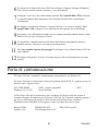
If You Have a Question
Best Power is committed to outstanding customer service. Worldwide Service is happy to help
you with your problems or questions. Trained service technicians are available 24 hours a day,
365 days a year. Just call Worldwide Service or the nearest Best Power office, or send a fax to
the Worldwide Service Fax number. Please have your unit’s serial number available when you
call; this number is on the back of the unit.
If you prefer you can contact Best on the World Wide Web to get more product information.
Best’s toll free Fax-on-Demand service is also available 24 hours a day to give you access to
technical notes and product information.
. . . . . .Worldwide Service:
. . . . . .Worldwide Service FAX:
. . . . . .World Wide Web Site:
. . . . . .Sales Fax on Demand:
. . . . . .Service Fax on Demand:
1-800-356-5737 (U.S., Canada) or 1-608-565-2100
1-608-565-7642 or 1-608-565-2509
http://www.bestpower.com
1-800-487-6813 (U.S. and Canada)
1-608-565-9499 ext. 9000
Best Power Offices Section (see Table of Contents), lists Best offices around the world.
Best Power reserves the right to change specifications without prior notice.
ENGLISH
2
Table of Contents
If You Have a Question . . . . . . . . . . . . . . . . . . . . . . . . . . . . . . . . . . . . . . . . . . . . . . . . .2
Safety Instructions . . . . . . . . . . . . . . . . . . . . . . . . . . . . . . . . . . . . . . . . . . . . . . . . . . . .4
UPS Features . . . . . . . . . . . . . . . . . . . . . . . . . . . . . . . . . . . . . . . . . . . . . . . . . . . . . . . .5
Wall Installation . . . . . . . . . . . . . . . . . . . . . . . . . . . . . . . . . . . . . . . . . . . . . . . . . . . . . .7
Rack Installation . . . . . . . . . . . . . . . . . . . . . . . . . . . . . . . . . . . . . . . . . . . . . . . . . . . . . .8
Quick Startup . . . . . . . . . . . . . . . . . . . . . . . . . . . . . . . . . . . . . . . . . . . . . . . . . . . . . . . .9
Symbols, LEDs and Audible Beeps . . . . . . . . . . . . . . . . . . . . . . . . . . . . . . . . . . . . . . .10
BestDock™ . . . . . . . . . . . . . . . . . . . . . . . . . . . . . . . . . . . . . . . . . . . . . . . . . . . . . . . . .12
Troubleshooting . . . . . . . . . . . . . . . . . . . . . . . . . . . . . . . . . . . . . . . . . . . . . . . . . . . . .12
Replacing the Batteries . . . . . . . . . . . . . . . . . . . . . . . . . . . . . . . . . . . . . . . . . . . . . . . .13
Battery Replacement Instructions . . . . . . . . . . . . . . . . . . . . . . . . . . . . . . . . . . . . .14
Communication Port . . . . . . . . . . . . . . . . . . . . . . . . . . . . . . . . . . . . . . . . . . . . . . . . . .15
DB-9 Pinouts . . . . . . . . . . . . . . . . . . . . . . . . . . . . . . . . . . . . . . . . . . . . . . . . . . . .16
Specifications . . . . . . . . . . . . . . . . . . . . . . . . . . . . . . . . . . . . . . . . . . . . . . . . . . . . . . .16
Warranty . . . . . . . . . . . . . . . . . . . . . . . . . . . . . . . . . . . . . . . . . . . . . . . . . . . . . . . . . . .18
Best Power Offices . . . . . . . . . . . . . . . . . . . . . . . . . . . . . . . . . . . . . . . . . . . . . . . . . . .21
Appendix A: Adjusting Voltage Settings . . . . . . . . . . . . . . . . . . . . . . . . . . . . . . . . . . .22
Trademarks
Fortress.TeleCom™ is a registered trademark of Best Power.
Windows is a registered trademark of Microsoft Corporation.
All other brand and product names are trademarks or registered trademarks of their respective
holders.
3
ENGLISH
Safety Instructions
IMPORTANT SAFETY INSTRUCTIONS!
SAVE THESE INSTRUCTIONS!
This User Guide contains important instructions for your Fortress.TeleCom that must be followed
during installation and maintenance of the UPS and batteries.
CAUTION!
Whenever the Fortress.TeleCom is “On,” there may be dangerous voltage present at the unit’s
outlets. This is true because the unit’s battery supplies power even if the unit is not plugged
into the wall outlet. The unit contains dangerous voltages.
To reduce the risk of electric shock, install in a temperature-controlled and humiditycontrolled indoor area free of conductive contaminants.
The power supply cord is intended to serve as the disconnect device. The socket-outlet shall
be near the equipment and shall be easily accessible.
With the exception of the user-replaceable batteries, all servicing of this equipment must be
performed by qualified service personnel.
Before maintenance or repair, all connections must be removed. Before maintenance, repair,
or shipment, the unit must be completely switched off and unplugged or disconnected.
The installation and use of this product must comply with all national, federal, state, municipal,
or local codes that apply. For assistance, call Best Power’s Worldwide Service or your local Best
Power office.
Refer to your Fortress and UNITY/I Safety Information Manual for additional safety instructions.
If the Fortress.TeleCom unit has been damaged during shipment, call your vendor immediately.
If the Fortress.TeleCom unit is stored, the batteries should be recharged every 6 months. If
stored above 25° Celsius (77° Fahrenheit), recharge the batteries more often.
ENGLISH
4
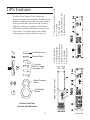
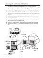
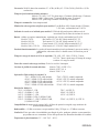
(C)
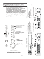
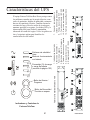
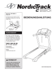
13. DB9 Communication Port
14. BestDock Access Panel
4. Battery Access Panel
5. Circuit Breaker
6. RJ11/RJ45 Jacks
8. 5-15 Outlets
% Load or
Battery Charge
(see page 10)
11. IEC 320 Outlets
(D)
3. Alarm/Program Button
Battery Mode
2. On/Standby Button
Line/Buck-boost
7. Input Power Connector or Cord
The Best Power Fortress.TeleCom provides
protection against power problems, including power
outages, brownouts, and sudden increases in power.
It also provides spike suppression and line noise
filtering to protect your equipment. Front panel
LEDs and an audible alarm keep you aware of the
unit’s status. Use the drawings on this and the
following page to identify features of the unit.
1. Status Indicators
UPS Features
(B)
Alarm/Program
Button
On/Standby
Button
Model 750 Front Panel
(A)
Fortress.TeleCom
Controls and Indicators
5
ENGLISH
ENGLISH
6
5 6
2 3
SITE WIRING
FAULT
13 7
4
5
7
1 2
3
8
9
4
14
13 14
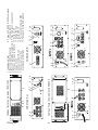
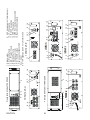
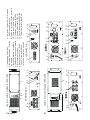
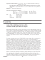
Models 1800/2250 Front Panel
1050/1425 U
SITE WIRING
FAULT
8 6
1
Models 1050/1425 Front Panel
1.
2.
3.
4.
5.
6.
7.
7 5
SITE WIRING
FAULT
7
12
13 7
14
13 14
10 13 14
5
8. 5-15 Outlets (1800 and 2250
have breaker)
9. 5-20 Outlets (2250 has breaker)
10. L5-30 Outlet
11. IEC 320 Outlets
12. CEE19 Outlet
13. DB9 Communication Port
14. BestDock Access Panel
8 9
6
6 11
1050/1425 E
5 6
11
Status Indicators
On/Standby Button
Alarm/Program Button
Battery Access Panel
Circuit Breaker
RJ11/RJ45 Jacks
Input Power Connector or Cord
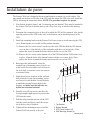
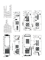
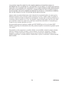
Wall Installation
The Fortress.TeleCom is shipped with screws and brackets to mount it to a wall surface. You
must attach one bracket to each side of the UPS, and then mount the UPS to the wall. Install the
UPS by following the instructions below. NOTE: The procedure requires two people.
1.
Note that the brackets (items 1 and 2 in drawing) are not identical. They must be attached to
the Fortress.TeleCom so that the narrow side of key slots is up, as shown in the drawing
below.
2.
Determine the construction type of the wall to which the UPS will be mounted. Also, decide
upon the position of the UPS on the wall, so the brackets can be attached properly to the
UPS.
3.
Install one mounting bracket on the Fortress.TeleCom at a time to avoid removing the UPS
cover. Removing the cover could void the product warranty.
3.a. Remove the five screws (item 3) on the top side of the UPS that hold the UPS bottom
cover in place. Align the holes of the top bracket with the cover-screw holes. Then,
replace the screws to attach the bracket and secure the cover to the UPS.
3.b. Remove the five screws on the bottom side of the UPS that hold the UPS bottom cover
in place. Align the holes of the bottom bracket with the cover-screw holes. Then,
replace the screws to attach the bracket and secure the cover to the UPS.
4.
Based upon the wall material, select the
required type of mounting screws (item 4): use
wood screws for wood studs, steel stud screws
for steel studs, or concrete screws for concrete
or concrete blocks.
5.
Mark desired screw locations on the wall and
drill pilot holes for the four mounting screws:
two screws for each bracket. Locate the holes
to match the spacing between holes in the
brackets, and make sure that all holes are
drilled into structural material.
6.
Partially screw all four screws into the wall,
leaving enough length exposed to position the
UPS onto the screws.
7.
With the help of another person, lift the UPS
onto the screws and lower it until the screws
are in the key slots of brackets.
8.
Tighten all four mounting screws to hold the
Fortress.TeleCom securely to the wall.
7
3
1
2
4
1
2
3
4
Top Bracket
Bottom Bracket
UPS Cover Screws (10)
Wall Mounting Screws (4)
ENGLISH
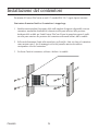
Rack Installation
To mount the Fortress.TeleCom in a 19-inch (483-mm) EIA 310 C standard rack, follow these
instructions.
Do not try to mount the unit if the rack is too wide. This procedure requires two people.
1.
Install a stationary shelf or supporting angle brackets (available as standard rack hardware
from electronics distributors) below the intended rack location for the Fortress.TeleCom.
Secure the shelf or brackets at both the front and back of the rack using bolts, nuts, and
washers.
2.
With the help of another person, carefully lift the unit onto the shelf or brackets and slide it
into the rack as shown below. The mounting holes on the sides of the front panel should
match the holes in the rack.
3.
Use bolts and washers to attach the unit securely to the rack.
ENGLISH
8
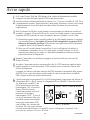
Quick Startup
1
If your Fortress.TeleCom UPS has a removable power cord, connect the power cord to the
back of the unit. Plug the UPS into a wall outlet. If the Fortress.TeleCom is a U model,
check to make sure that the rear panel Site Wiring Fault light is not lit.
2
Let the unit charge the battery for at least 3 hours (7 hours for 1425 VA model if it is fully
loaded). You may use the unit while the battery charges, but the battery backup runtime will
be reduced until the battery is fully charged.
3
Start the Fortress.TeleCom by pressing and holding the On/Standby button (large button in
the center of the front panel) in for about one second. Note: To turn the unit either on or off,
the On/Standby button must be pressed for about one second.
3.a. When it starts, the unit beeps and lights the front panel lights, turns them off, and lights
them again. Next, the Fortress.TeleCom applies AC output to the back panel
receptacles. It does a brief self test, turning various front panel lights off and on.
3.b. After 30 seconds or less, the self test is complete. The top and bottom green lights will
come on and remain on. If the unit beeps, or if the top light does not remain on even
though input power is available from the wall outlet, go to the Troubleshooting section.
4
5
Switch off the equipment you want to protect, and plug each load into the outlets on the
back of the Fortress.TeleCom.
Switch on the protected equipment, one load at a time. If the UPS beeps an alarm when you
start your equipment, the UPS may be overloaded. See the Troubleshooting section.
The bottom four lights on the front of the UPS show the % of load capacity that your
equipment is using. See Symbols, LEDs and Audible Beeps Section for more information.
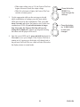
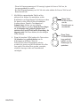
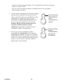
6
The RJ-11 or RJ-45 Surge Protection
750
1050, 1425, 1800 & 2250
jacks will protect equipment that uses
an RJ-11 or RJ-45 connection. Plug the OUT
IN
OUT
IN
10BASE-T network connection (or
phone, fax or modem line for U
models) into the surge protection jack
IN
OUT
labeled “IN” on the back of the
Fortress.TeleCom. Plug the protected
RJ-11 or RJ-45 Jacks
equipment into the surge protection jack
labeled “OUT.” Network cabling is not provided. Network only on European model; do not
connect any TNV equipment such as telephone, fax or modem to the circuitry. It may only
be used for network protection purposes, on E models. This connection is optional. It is not
needed to use the Fortress.TeleCom.
OR
9
ENGLISH
7
Please fill out the warranty registration card and return it to your local Best Power office. If
you are in the U.S.A. or Canada and you would like to activate the Warranty for Transient
Voltage Surge Suppression, please return the registration card within 10 days of installation.
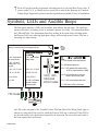
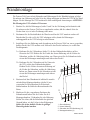
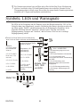
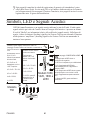
Symbols, LEDs and Audible Beeps
The front panel indicators (LEDs) and an audible beep indicate the unit status. The unit beeps
whenever the unit is on battery power or an alarm is present. See Table 1 for information about
the LEDs and Table 2 for information about beep coding. In the figure below, bucking means
that Fortress.TeleCom is reducing high input voltage, and boosting means Fortress.TeleCom is
increasing low input voltage.
Steady: Fortress is operating on AC line.
Blinking: Fortress is bucking or boosting input AC line.
A, B, C, and D indicate
per cent of full load:
A, B, C, and D indicate
battery charge:
D
A, B, C, & D, with D
flashing, load = 110%
or higher.
C
A, B, C, & D = 75-100%
A, B, C & D = 75-100 %
A, B, & C = 50-75%
B, C & D = 50-75 %
A & B = 25-50%
C & D = 25-50 %
A = 0-25%
D = 0-25 %; if D flashes,
less than 2 minutes
of runtime remain.
750 model
D
C
B
A
B
1050, 1425,
1800 and
2250 models
C = UPS shutdown due to output overload.
B = UPS failed the battery test.
B & C = UPS shutdown from communication
at RS-232, remote shutdown or SNMP.
A & B = UPS shutdown due to main relay
failure or short circuit on output.
A & C = UPS over-temperature shut down.
A = UPS Fault; Fan Fail or Overcharge
A
An LED on the rear panel of the U model Fortress.TeleCom (labled Site Wiring Fault) lights to
indicate a wiring fault in the circuit to which the Fortress.TeleCom is connected. If this LED is
on, the outlet needs to be checked and repaired by an electrician. Do not use this outlet until it
has been repaired and verified safe.
ENGLISH
10
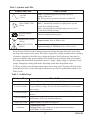
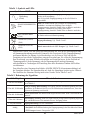
Table 1: Symbols and LEDs
Symbols and LEDs
What It Means
Steady: Acceptable input power is present. The unit is
running on line power.
Off: No input power is present or the unit is switched off.
AC LINE
(Green)
LINE CORRECTION
(Green)
Blinking: The unit is boosting or bucking utility power.
Boost = Automatically increases low input power to prevent
the unit from switching to battery.
Buck = Automatically decreases high input power to prevent
the unit from switching to battery.
BATTERY MODE
(Yellow)
The unit is running on battery power.
OVERLOAD, (D LED)
(Yellow)
Output Overload: Refer to Tables 2 and 3.
WARNING, (D LED)
(Yellow)
Replace the Battery or UPS Fault. Refer to Tables 2 and 3.
If your Fortress.TeleCom runs on batteries frequently because the input utility line varies often,
you may want to adjust your Fortress.TeleCom to accept wider voltage variations before switching
to batteries. Appendix A describes how to adjust the Fortress.TeleCom from the front panel in
response to specific utility power problems. You should have an electrician check your nominal
line voltage and determine if the problem is due to a “Surge” (high) voltage or “Brownout” (low)
voltage. Changing the setting without this knowledge could make the problem worse.
To silence an alarm, press the alarm silence button on the front panel. The beep will stop, but the
alarm light will stay on. Note: Silencing the alarm does not solve the problem that caused it. See
Tables 2 and 3.
Table 2: Audible Beeps
Number of Beeps
What It Means
1 every 10 seconds
Line Loss: The unit is on battery power. See Table 3 for more information.
2 every 10 seconds
Low Battery Alarm: The unit was running on battery power and shut down due
to very low battery voltage. The unit will restart automatically when acceptable
power returns.
3 every 10 seconds
Replace the Battery: The battery needs to be replaced. See “Replacing the
Batteries.”
3 every 5 minutes
Battery Undercharged: While on line operation, low battery voltage indicates
that the battery will provide minimal backup time.
1 beep every second
Continuous
Output Overload: Too much load equipment.
1) Output Short Circuit
2) Starting Fault: Input voltage out of range when unit is turned on.
3) UPS Fault: UPS internal failure.
11
ENGLISH
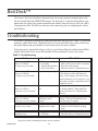
BestDockÔ
The Fortress.TeleCom’s BestDock communication slot accepts optional communication cards,
like the internal BestLink SNMP/WEB adapter. The insertion of a card into the BestDock communication slot replaces the normal communication channel from the Fortress.TeleCom’s DB-9
Communication Port. The DB-9 port becomes the connection point for configuring the card in
the BestDock.
Troubleshooting
If you have a question or problem, the troubleshooting table may help. (See Table 3.) If you need
assistance, phone Best Power’s Worldwide Service or your local Best Power office. Please have
the model number and serial number (located on the rear of the unit) available.
If the unit must be returned, Best Power will give you a Return Materials Authorization (RMA)
number. Phone Best Power for an RMA number before returning the unit for any reason.
Table 3: Troubleshooting
Problem
Possible Reasons
Utility power outage.
Loose plug.
Tripped circuit breaker.
Power cord failure.
What To Do
Yellow BATTERY LED on,
Green LINE LED off,
one beep every 10 seconds.
1.
2.
3.
4.
1.
2.
3.
4.
Wait for power to return.
Make sure the power cord is connected.
Reset the circuit breaker.
Phone Best Power’s Worldwide Service.
Yellow BATTERY LED on,
Green LINE LED off,
two beeps every 10 seconds.
Very low battery voltage.
Yellow WARNING LED on,
Green LINE LED on,
three beeps every 10 seconds.
Unit has failed the battery Turn the unit off and then on to reset
test.
the “Replace Battery” alarm and LEDs.
Replace the battery. See “Replacing the
Batteries.”
Yellow WARNING LED off,
Green LINE LED on,
three beeps every five minutes.
Battery not charged
following a power
outage.*
Plug the unit into a working wall outlet for
at least 8 hours to allow the batteries to
charge. After recharge, if the unit will not
operate on batteries, or it beeps twice every
10 seconds on batteries, phone Best Power’s
Worldwide Service.
Use the unit on utility power; wait for full
recharge. The beeps automatically stop
when the battery is charged.
Yellow OVERLOAD LED blinking, The power required by the 1. Remove load equipment.
one beep every second.
equipment is too high.
2. Reduce load level until the beeping
stops.
Yellow WARNING LED on,
continuous beep.
1. Output short circuit.
2. UPS Fault
1. Remove load and reset UPS.
2. Phone Best Power’s Worldwide Service.
* If the battery does not recharge after 24 hours in the 3-beeps/5-minute alarm state, the alarm changes to
3 beeps/10 seconds, indicating the battery must be replaced.
ENGLISH
12
Replacing the Batteries
The Fortress.TeleCom batteries are user-replaceable and can be replaced while the
Fortress.TeleCom has AC input applied and powers the loads. This means that, if necessary, you
can replace the batteries while the UPS is running. Before you replace the batteries, make sure
that you read the safety information below.
Note:
If you have a power outage while you are replacing the batteries, the UPS will not be
able to run on battery power and your protected equipment will shut down.
CAUTION!
The batteries used in the UPS and battery pack can produce dangerous voltage and high
current. Therefore, the batteries may cause severe injury if their terminals contact a tool or the
UPS cabinet. Be very careful to avoid electrical shock and burns from contacting terminals
while you replace the batteries.
Batteries contain caustic acids and toxic materials and can rupture or leak if mistreated.
Remove rings and metal wristwatches or other jewelry. Do not carry metal objects in your
pockets: these objects could fall into the UPS.
Never allow any tool to contact both a battery terminal and the UPS cabinet or another
battery terminal. Do not lay tools or metal parts on top of batteries.
To ensure continued superior performance of your UPS and to maintain proper charger
operation, you must replace the UPS batteries with the same number and type of batteries.
These batteries must be the same type as the original batteries: valve-regulated, low
maintenance. The replacement batteries should have the same voltage and ampere-hour rating
as the original batteries.
Assume that old batteries are fully charged. Use the same precautions you would use when
handling a new battery. Do not short battery terminals with a cable or tool! Batteries contain
lead. Many areas have regulations about disposing of used batteries. Please dispose of old
batteries properly. DO NOT dispose of batteries in a fire because the batteries could explode.
Do not open or mutilate batteries. Released electrolyte is harmful to the skin and eyes. It may
be toxic.
This equipment may produce ozone. Take precautions to ensure that the concentration of
ozone is limited to a safe value (0.1 ppm {0.2 mg / m3} calculated as an 8-hour time-weighted
average).
13
ENGLISH
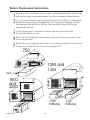
Battery Replacement Instructions
1
2
Phone Best Power’s Worldwide Service to order a replacement battery pack. It must be the
same type and rating of the original batteries. See Battery information in Specifications.
3
4
5
Use the drawings below to identify the location of the battey pack in the model
Fortress.TeleCom that you have.
If it is necessary, the batteries may be replaced while the Fortress.TeleCom is running with
the protected equipment attached. Option: You may switch off and unplug the protected
load equipment from the Fortress.TeleCom. Then, turn off the Fortress.TeleCom and
disconnect the line cord.
Remove the screws holding the exterior battery access panel (1) to the front panel. Set the
screws and panel aside.
Remove the screws holding the interior panel (2) to the battery chamber. Use care to avoid
dropping screws inside the unit. Set the screws and panel aside.
750
2
1
1050 and
1425
Black(-)
Red (+)
1800
and
2250
1
2
1
Black (-)
Red (+)
1050
Batteries
ENGLISH
2
14
1425
Batteries
6
7
Use the tabs attached to the batteries to remove the batteries from the Fortress.TeleCom. Do
not pull batteries out by pulling on battery terminals or cables.
8
9
Reconnect the cables to the new battery pack; red to positive (+), black to negative (-).
For 1800 and 2250 models: Plug the battery cable into the unit’s cable jack.
Disconnect the red and black cables from the used battery pack.
For 1800 and 2250 models: Disconnect the battery plug from the cable jack in the unit.
Dispose of old batteries properly.
Position the battery cables so they will not be pinched by the interior panel or the battery
pack. Slide the battery pack into the unit.
10
11
Use the screws removed earlier to re-install the interior panel to the battery chamber and the
exterior panel to the front panel.
12
Reconnect the load equipment. Switch on the protected load equipment one piece at a time.
If you followed the option in step 2: Reconnect the line cord to the Fortress.TeleCom and
turn the unit on.
Communication Port
The Fortress.TeleCom is plug-and-play compatible with Windows 95.
The Fortress.TeleCom comes equipped with CheckUPS II power management software.
Instructions included with the CheckUPS II CD tell you how to install the software. An interface
cable for the following systems is provided.
SCO UNIX/XENIX
Windows 3.X, 95 and NT
UNIX and Compatible Systems
Novell NetWare
OS/2
Best Power offers interface kits that allow you to connect many other computer systems to the
Fortress.TeleCom communication port. For the following computer systems, or specific information on Best Power interface kits, call Best Power’s Worldwide Service or your local Best Power
dealer.
Banyan VINES
Lantastic v4.0
IBM RS/6000 AIX
LAN Manager/Server v2.0
15
IBM AS/400 special
ENGLISH
DB-9 Pinouts
Pin 1
Pin 2
Pin 3
Pin 4
Pin 5
Pin 6
Pin 7
Pin 8
Pin 9
RS232 Receive Data: Receives incoming RS232 communication data.
RS232 Transmit Data: Sends outgoing RS232 communication data.
Normally Open On-Battery Contact: A normally open contact that closes 15 seconds
(pulls to Common) after the UPS switches to battery power.
Common: The signal ground for all signal pins.
Normally Open Low-Battery-Alarm Contact: A normally open contact that closes
(pulls to Common) during a Low Battery Alarm. This tells CheckUPS II and other
shutdown software when to start a computer shutdown.
Plug and Play Sense for Windows 95.
Remote Shutdown: Connecting this pin to Common for at least 5 seconds, while the
UPS is operating on battery, shuts the UPS off after 120 seconds.
Normally Closed On-Battery Contact: A normally closed contact that opens
15 seconds (releases from Common) after the UPS switches to battery power.
Unused.
Contacts consist of open collector circuits capable of switching up to +30 VDC, 6 mA resistive
load.
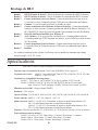
Specifications
Best Power reserves the right to change specifications without prior notice.
Line Transient Protection: Passes ANSI/IEEE C62.41 Category A testing.
Safety Compliance: Model U: Tested to UL1449; listed to UL1778, and CAN/CSA C22.2 No. 107.1 M91.
Model E: TÜV/GS listed.
EMC Compliance: Model U: FCC Class A; except 750 VA model complies to FCC Class B.
Model E: CISPR 22 Class B, Vfg 243-91/46-92 B, EN55022, CE Mark Self-certified
to: CE Marking Directive 93/68/EEC, Low Voltage Directive 73/23/EEC
Noise (RF) Suppression: Full-time EMI/RFI filtering.
Efficiency: > 95% on line.
Capacity VA/Watts: 750VA / 450W; 1050VA / 670W; 1425VA / 950W; 1800VA / 1260W;
2250VA / 1600W.
Voltage Nominal: Model U: 120 VAC, Model E: 230 VAC
Voltage Range: Model U: 0 to 160 VAC operating on battery and buck/boost; 96 to 146 VAC operating on
buck/boost only.
Model E: 0 to 300 VAC operating on battery and buck/boost; 188 to 270 VAC operating
on buck/boost only.
Frequency: 50/60 Hz auto-sensing 55 - 65 Hz (60 Hz); 45 - 55 Hz (50 Hz) (50/60 Hz ± 0.5 Hz on battery.)
ENGLISH
16
Minimum Runtime (minutes): 750, 1050, and 1425VA Models: Full load: 6.5 minutes.
Half load: 15 minutes.
1800VA Models: Full load: 7.5 minutes. Half load: 22 minutes.
2250 VA Models: Full load: 5 minutes. Half load: 12 minutes.
Transfer Time: 4 ms typical.
Telephone line surge suppression for U models: per Bellcore 1089: 1.2/50msec waveform, ± 2kV peak,
Compliant to UL497A.
Site Wiring Fault Indicator for U Models: Back panel LED indicates phase reversal fault in input utility
line.
Battery: Sealed, maintenance-free, valve-regulated, UL 924 recognized.
750 VA Models:
Two 12 V, 9 AH batteries.Nominal Voltage is 24 VDC.
1050 VA Models:
Three 12 V 9 AH batteries. Nominal Voltage is 36 VDC.
1425 VA Models:
Four 12 V 9 AH batteries. Nominal Voltage is 48 VDC.
1800 and 2250 VA Models: Eight 6 V, 12.0 AH batteries. Nominal Voltage is 48 VDC.
Automatic Battery Test: Automatic battery test occurs upon startup and every 14 days thereafter. Alarm
will sound if the battery fails this test.
Battery Recharge Time (to 95% of capacity): 750 VA, 1050 VA, 1425 VA, 1800 VA and 2250 VA:3 hours;
1425 VA: 7 hours with output fully loaded. Recharge time is
lower with reduced load.
Overcurrent Protection (on line): All Models: Circuit Breaker.
Input Fault Current (maximum): 750E and 1050E Models: 15 A.
1425E Model: 26.1 A.
2250E Models: 35 A.
AC input Plug/Cord Information:
750 U - NEMA 5-15P, cord attached.
1050 U - NEMA 5-15P, cord attached.
1425 U - NEMA 5-15P, cord attached.
1800 U - NEMA 5-20P, cord attached.
2250 U - NEMA L5-30P, cord attached.
AC Output Distribution:
750 U - (6) NEMA 5-15R.
1050 U - (6) NEMA 5-15R.
1425 U - (6) NEMA 5-15R.
1800 U - (4) NEMA 5-15R, (2) NEMA 5-20R.
2250 U - (4) NEMA 5-15R, (2) NEMA 5-20R,
(1) NEMA L5-30R.
750 E - CEE 22, recessed plug.
1050 E - CEE 22, recessed plug.
1425 E - CEE 22, recessed plug.
2250 E - CEE 19, recessed plug.
750 E - (4) CEE 22.
1050 E - (4) CEE 22.
1425 E - (4) CEE 22.
2250 E - (4) CEE 22, (1) CEE 19.
Load Compatibility: Can support 100% power factor corrected, switch-mode power supply load.
Audible Noise: < 45 dBa at one meter, except 1800 and 2250 VA models which are < 55 dBa at one meter.
Ventilation: Air around the unit must be free of dust, chemicals, or other materials that corrode or
contaminate. Air must be free to move around the unit.
17
ENGLISH
Operating Temperature: 32° - 104° F (0° - 40° C).
Storage Temperature: 5° - 122° F (-15° to +50° C). Battery life is reduced above 77° F (25 ° C).
If the Fortress.TeleCom unit is stored, the batteries should be recharged every 6
months. If stored above 77° F (25° C), recharge the batteries more often.
Humidity: 5% - 95% RH (non-condensing).
Dimensions (Height x Width x Depth): 750 VA:
1050 & 1425VA:
1800 & 2250 VA:
Weight: 750:
1050:
39.6 lbs. (18.0 kg)
51.3 lbs (23.3 kg)
3.5 in. x 17.6 x 18.7 (88 x 448 x 475 mm)
5.3 in. x 17.6 x 18.7 (133 x 448 x 475 mm)
7.0 in. x 17.6 x 18.7 (178 x 448 x 475 mm)
1425:
57.2 lbs. (26.0 kg)
1800 & 2250: 86.0 lbs. (39.1 kg)
Warranty
LIMITED TWO YEAR WARRANTY
Standard Warranty For All Purchases
BEST POWER, a division of SPX Corporation, (hereinafter called BEST POWER) warrants that each product
sold by BEST POWER is compatible with existing commercially available computer equipment with enclosed
power supplies and is free from defects in materials and workmanship under normal use and service. This
warranty is applicable only to the initial retail purchaser (PURCHASER), and is not transferable. The duration
of this warranty is two (2) years from the date of the first retail sale or the date of delivery to the
PURCHASER, whichever occurs first, subject to the following conditions.
If the PURCHASER discovers within the duration of this warranty a failure of the product to perform
compatibly with presently existing computer equipment or a defect in material or workmanship, the
PURCHASER must promptly notify BEST POWER in writing within the duration of the warranty or not
later than one month after expiration of the warranty. BEST POWER’s obligation under this warranty is
limited to the replacement or repair, subject to the conditions specified below, of such product returned
intact to BEST POWER which shall appear to BEST POWER, upon inspection, to have been either
incompatible or defective. Replacement or repair will be made at BEST POWER’s Worldwide Service,
Highway 80, Necedah, Wisconsin 54646, U.S.A. Such repair or replacement shall be at BEST POWER’s
expense. This warranty does not cover any taxes which may be due in connection with replacement or
repair, nor any installation, removal, transportation or postage costs. These expenses will be paid by
PURCHASER. If BEST POWER is unable to repair or replace the product to conform to this warranty after
a reasonable number of attempts, BEST POWER will refund the purchase price. Remedies under this
warranty are expressly limited to those specified above.
TO THE EXTENT ALLOWED BY LAW, BEST POWER DISCLAIMS ALL OTHER WARRANTIES,
EXPRESS OR IMPLIED, INCLUDING, BUT NOT LIMITED TO, ANY IMPLIED WARRANTIES OF
MERCHANTABILITY OR FITNESS FOR A PARTICULAR PURPOSE, AND ANY IMPLIED
WARRANTY OF MERCHANTABILITY OR FITNESS FOR A PARTICULAR PURPOSE ON THIS
PRODUCT IS LIMITED IN DURATION TO THE DURATION OF THIS WARRANTY. TO THE
EXTENT ALLOWED BY LAW, BEST POWER SHALL NOT BE LIABLE FOR ANY SPECIAL,
INCIDENTAL, OR CONSEQUENTIAL DAMAGES INCLUDING, BUT NOT LIMITED TO, LOSS OF
PROFITS, INJURIES TO PROPERTY, LOSS OF USE OF THE PRODUCT OR ANY ASSOCIATED
EQUIPMENT.
ENGLISH
18
Some states do not allow limitations on how long an implied warranty lasts, so that the above limitation on
duration of implied warranties may not apply to you. Some states do not allow the exclusion or limitation of
incidental or consequential damages, so the above limitation or exclusion may not apply to you. This warranty gives you specific legal rights, and you may also have other rights which vary from state to state. You
are advised to consult applicable state laws.
No warranty is made with respect to other products sold by BEST POWER which do not bear the name
BEST POWER, and no recommendation of such other product shall imply or constitute any warranty with
respect to them. This warranty does not cover repair or replacement because of damage from unreasonable
use (for example only, damage from road hazard, accident, fire or other casualty, misuse, negligence, or
incorrect wiring) and any use or installation not in conformance with instructions furnished by BEST
POWER, or repairs or replacements needed because of modifications or parts not authorized or supplied by
BEST POWER.
LIMITED WARRANTY
Transient Voltage Surge Suppression Circuitry
(For U.S. and Canadian Purchasers Only)
BEST POWER, a division of SPX Corporation, (“BEST POWER”) hereby warrants the transient voltage
surge suppression circuitry in each FERRUPS®, FORTRESS®, FORTRESS.TeleCom™, PATRIOT®,
PATRIOT® PRO, UNITY/I™, CITADEL®, or SPIKEFREE™ product (hereinafter called “Product”) sold by it
for installation in the United States of America and Canada to be free from defects in material and
workmanship under normal use and service for the lifetime of the Product, beginning with the date of sale
to the initial retail purchaser, subject to the following conditions.
This warranty is applicable only to the initial retail purchaser (hereinafter called PURCHASER), is not
transferable, and is limited to the following remedies:
1.
The replacement or repair of the transient voltage surge suppression circuitry in each Product that
is returned intact to BEST POWER and which shall appear to BEST POWER upon inspection to
have been defective in material or workmanship or to have been damaged through normal use;
2.
The reimbursement to the PURCHASER of up to $25,000 per occurrence of documented physical
damage to specified computer equipment connected to a Product where such damage could have
been prevented by transient voltage surge suppression circuitry as detailed in BEST POWER’s
specification for the Product sold.
This warranty is made in addition to BEST POWER’s Limited Two Year Warranty.
This warranty does not include any taxes which may be due in connection with replacement or repair nor
any installation, transportation or postage costs. These expenses will be paid by PURCHASER.
Replacement or repair will be made at BEST POWER’s Worldwide Service, Highway 80, Necedah,
Wisconsin 54646, U.S.A.
This warranty does not cover repair or replacement because of damage from unreasonable use (damage
from road hazards, accident, fire or other casualty, misuse, negligence, incorrect wiring) and any use or
installation not in conformance with instructions furnished by BEST POWER, or repairs or replacements
needed because of modifications or parts not authorized or supplied by BEST POWER.
This warranty is operable only upon the written acceptance by BEST POWER of an application by the
PURCHASER on BEST POWER’s standard form for the above warranty coverage for the Product sold. In
such application, the PURCHASER shall represent that the Product sold has been properly installed and
19
ENGLISH
grounded in accordance with instructions received from BEST POWER, and the PURCHASER shall also
specify the computer equipment to which the Product sold has been connected and the location of the
computer equipment. This warranty will not apply to any equipment not specified in the application by the
PURCHASER as protected equipment.
EXCEPT AS EXPRESSLY SET FORTH IN THIS WARRANTY AND BEST POWER’S LIMITED TWO
YEAR WARRANTY, BEST POWER MAKES NO OTHER WARRANTIES, AND TO THE EXTENT
ALLOWED BY LAW, BEST POWER DISCLAIMS ALL OTHER WARRANTIES, EXPRESS OR
IMPLIED, INCLUDING, BUT NOT LIMITED TO, ANY IMPLIED WARRANTIES OF
MERCHANTABILITY OR FITNESS FOR A PARTICULAR PURPOSE.
REMEDIES UNDER THIS WARRANTY ARE EXPRESSLY LIMITED TO THE REPAIR OR
REPLACEMENT OF PRODUCTS AND THE REIMBURSEMENT SPECIFIED ABOVE, AND TO THE
EXTENT ALLOWED BY LAW ANY CLAIMS FOR LOSS ARISING OUT OF THE FAILURE OF
PRODUCTS TO PERFORM FOR ANY PERIOD OF TIME, OR SPECIAL, INDIRECT, INCIDENTAL
OR CONSEQUENTIAL DAMAGES OR OTHER ECONOMIC LOSS ARE EXPRESSLY EXCLUDED.
Some states do not allow limitations on how long an implied warranty lasts, so that the above limitation on
duration of implied warranties may not apply to you. Some states do not allow the exclusion or limitation of
incidental or consequential damages, so the above limitation or exclusion may not apply to you. This
warranty gives you specific legal rights, and you may also have other rights which vary from state to state.
You are advised to consult applicable state laws.
ENGLISH
20
Best Power Offices
Best Power
P.O. Box 280
Necedah, Wisconsin 54646 U.S.A.
Telephone: 1-608-565-7200
Toll-free (U.S.A. and Canada): 1-800-356-5794
FAX: 1-608-565-2221
International FAX: 1-608-565-7675
E-mail: [email protected]
Best Power Technology Mexico, S.A. de C.V.
Golfo de Riga, 34
Colonia Tacuba
México D.F. 11410
MÉXICO
Telephone: (52) 5-527-8009
Toll-free (in Mexico): 1-800-711-8978
FAX: (52) 5-399-1320
E-mail: [email protected]
Best Power Technology, Pte. Ltd.
19 Neyhal Road
SINGAPORE 628584
Telephone: (65) 265-6866
FAX: (65) 265-6636
E-mail: [email protected]
Best Power Technology Limited
BEST House
Wykeham Industrial Estate
Moorside Road
Winchester
Hampshire
S023 7RX
ENGLAND
Telephone: (44) 1962-844414
Toll-Free (in England): 0800 378444
FAX: (44) 1962-841846
E-mail: [email protected]
Best Power Technology Germany, GmbH
Am Weichselgarten 23
D-91058 Erlangen
GERMANY
Telephone: (49) 9131-77700
Toll-Free (in Germany): 0130-84-7712
FAX: (49) 9131-7770-444
E-mail: ger.service.gensig.com
Borri Elettronica Industriale Srl
Via dei Lavoratori, 124
20092 Cinisello Balsamo (Mi)
Milan, ITALY
Telephone (39) 02-6600661-2
FAX: (39) 02-6122481
Sola Australia Ltd.
13 Healey Road
Dandenong, Victoria 3175
AUSTRALIA
Telephone: (61) 3-9706-5022
FAX: (61) 3-9794-9150
21
ENGLISH
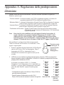
Appendix A: Adjusting Voltage Settings
When the unit is not sounding an alarm, you can use the Alarm/Program button shown below to
change the following:
• Nominal Voltage — The normal voltage the UPS is programmed to expect, and the nominal UPS
output voltage under line loss conditions.
• Buck — The input voltage at which the Fortress.TeleCom decreases voltage before providing
output because the input voltage is too high.
• Boost — The input voltage at which the Fortress.TeleCom increases voltage before providing
output because the input voltage is too low.
• Transfer to Inverter — The point at which the UPS switches to inverter (battery power), either
because AC input voltage is very low or because it is very high.
Note:
Make sure you want to change these values before you
start the procedure below. Once you press the button
shown for 10 seconds, the values will change to the
default values, and any previous changes you have
made will be lost. If you have a question, contact the
nearest Best Power office, or call Worldwide Service
at 1-800-356-5737 or 1-608-565-2100.
Press this
button for 10
seconds (until
all of the lights
blink).
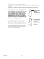
Do not change voltage settings when unit is operating on batteries. To change the values, follow these
steps:
1.
Press the button shown until LEDs on the front of the Fortress.TeleCom blink. After the LEDs
blink, three will stay lit and the Fortress.TeleCom will beep for one second.
2.
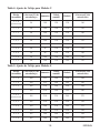
The LEDs that are lit show which voltage settings are selected. The LEDs are numbered in the
drawing below to help you identify them. Tables 4 and 5 on page 19 show the voltage settings
for each possible combination of LEDs.
1
1
For example, the U model default setting has LEDs 2, 3, and
4 lit (see diagram). You will find this combination of LEDs in
the first row of Table 4. This row shows the following:
2
3
2
(D)
4
(C)
• With 96 volts input or lower, the Fortress.TeleCom
5
switches to battery power.
(B)
• When input voltage drops to 109, the Fortress.TeleCom
6
(A)
begins to increase (boost) the output voltage.
• 120 is the nominal or expected input voltage.
LED Numbers
ENGLISH
22
3
4
5
6
Default Setting
• When input voltage rises to 130, the Fortress.TeleCom
begins to decrease (buck) the output voltage.
• With 146 volts input or higher, the Fortress.TeleCom
switches to battery power.
3.
4.
Use the appropriate table on the next page to decide
which combination of settings you need; note which
LEDs must be lit for this combination. Then, press (for
about 1 second) and release the button to move to the next
combination of LEDs. If you hold the button in longer
than 10 seconds, the Fortress.TeleCom will save the
setting that is displayed. Continue pressing and releasing
the button until the proper LEDs are lit.
Press this button
BRIEFLY to
scroll through the
settings.
Press this button
for 10 SECONDS
to save your
changes.
Once the correct LEDs are lit, press and hold the button for
10 seconds to save your changes. If the Fortress.TeleCom is
running on AC input power, the display will change back to
the percent of full load. The new values will take effect after
the display returns to normal mode.
23
ENGLISH
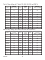
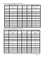
Table 4: Voltage Settings for U Models (750, 1050, 1425, 1800, and 2250 VA)
LEDs Lit
To Inverter
(Input AC is Low)
Boost
Nominal
Voltage
Buck
To Inverter
(Input AC is High)
2, 3, 4
(Default)
96
109
120
130
146
1, 3, 4
96
109
120
138
156
2, 3, 5
90
104
120
130
146
1, 3, 5
90
104
120
138
156
3, 4, 5
90
104
110
120
130
2, 4, 5
90
104
110
130
146
3, 4, 6
90
96
110
120
130
2, 4, 6
90
96
110
130
146
1, 2, 4
96
109
128
146
156
1, 2, 5
90
104
128
146
156
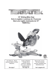
Table 5: Voltage Settings for E Models (750, 1050, 1425, and 2250 VA)
LEDs Lit
To Inverter
(Input AC is Low)
Boost
Nominal
Voltage
Buck
To Inverter
(Input AC is High)
2, 3, 4
200
222
240
250
284
1, 3, 4
200
222
240
264
290
2, 3, 5
188
210
240
250
284
1, 3, 5
188
210
240
264
290
3, 4, 5
(Default)
188
210
230
244
270
2, 4, 5
188
210
230
250
284
3, 4, 6
180
200
230
244
270
2, 4, 6
180
200
230
250
284
4, 5, 6
165
188
208
222
244
3, 5, 6
165
188
208
244
270
ENGLISH
24
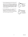
For Users in the United States only
For 750 VA Model U
Note: This equipment has been tested and found to comply with the limits for a Class B device pursuant to part 15 of
FCC Rules. These limits are designed to provide reasonable protection against harmful interference when this equipment is operated in a commercial environment. This equipment generates, uses, and can radiate radio frequency energy and, if not installed and used in accordance with the instruction manual, may cause harmful interference to radio
communications. However, there is no guarantee that interference will not occur in a particular installation. If this
equipment does cause harmful interference to radio or television reception, which can be determined by turning the
equipment off and on, the user is encouraged to try to correct the interference by one or more of the following measures:
Reorient or relocate the receiving antenna.
Increase the separation between the equipment and the receiver.
Connect the equipment into an outlet on a circuit different from that to which
the receiver is connected.
Consult the dealer or an experienced radio/TV technician for help.
For 1050, 1425, 1800, and 2250 VA Model U
Note: This equipment has been tested and found to comply with the limits for a Class A digital device pursuant to
Part 15 of FCC Rules. These limits are designed to provide reasonable protection against harmful interference when
this equipment is operated in a commercial environment. This equipment generates, uses, and can radiate radio frequency energy and, if not installed and used in accordance with the instruction manual, may cause harmful interference to radio communications. Operation of this equipment in a residential area is likely to cause harmful interference
in which case the user will be required to correct the interference at his/her own expense.
Changes or modifications not expressly approved by the party responsible for compliance could void the
user’s authority to operate the equipment.
For Users in Canada only
For 750 VA Model U
This Class B interference causing equipment meets all requirements of the Canadian Interference Causing
Equipment Regulations ICES-003.
Cet appareil numerique de la Classe B respecte toutes les exigences du Reglement sur le materiel brouileur
du Canada.
For 1050, 1425, 1800, and 2250 VA Model U
This Class A interference causing equipment meets all requirements of the Canadian Interference Causing
Equipment Regulations ICES-003.
Cet appareil numerique de la Classe A respecte toutes les exigences du Reglement sur le materiel brouileur
du Canada.
25
ENGLISH
Si vous avez des questions à poser
Best Power s'est engagé à fournir un service client remarquable. Le service international est
heureux de vous aider avec vos problèmes et questions. Un technicien de service est disponible
24 heures par jour, 365 jours par an. Appelez simplement le Service International ou le bureau le
plus proche de Best Power, ou envoyez un fax au numéro de fax du Service International. Ayez
sous la main votre numéro de série lorsque vous appelez; ce numéro est se trouve sur l'arrière de
votre appareil.
Si vous préférez, vous pouvez contacter Best sur Internet pour obtenir plus d'informations sur le
produit.
Le service à appel gratuit par fax sur demande est aussi disponible 24 heures par jour pour vous
donner l'accès aux notes techniques et informations sur le produit.
. . . . . .Service International :
. . . . . .Service international par FAX :
. . . . . .Site Web :
. . . . . .Fax de vente sur demande :
. . . . . .Fax de service sur demande :
+1 800 356 5737 (Etats-Unis et Canada) ou +1 608 2100
+1 608 565 7642 ou +1 608 565 2509
http://www.bestpower.com
+1 800 487 6813 (Etats-Unis et Canada)
+1 608 565 9499 poste 9000
La partie Bureaux de Best Power (voir table des matières) donne la liste des bureaux Best dans
le monde.
Best Power se réserve le droit de changer les spécifications sans préavis.
FRANÇAIS
26
Table des matières
Si vous avez des questions à poser . . . . . . . . . . . . . . . . . . . . . . . . . . . . . . . . . . . . . . . .26
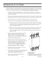
Instructions sur la sécurité . . . . . . . . . . . . . . . . . . . . . . . . . . . . . . . . . . . . . . . . . . . . . .28
Caractéristiques de l'UPS . . . . . . . . . . . . . . . . . . . . . . . . . . . . . . . . . . . . . . . . . . . . . .29
Installation de paroi . . . . . . . . . . . . . . . . . . . . . . . . . . . . . . . . . . . . . . . . . . . . . . . . . . .31
Installation de châssis . . . . . . . . . . . . . . . . . . . . . . . . . . . . . . . . . . . . . . . . . . . . . . . . .32
Démarrage rapide . . . . . . . . . . . . . . . . . . . . . . . . . . . . . . . . . . . . . . . . . . . . . . . . . . . .33
Symboles, diodes et bips sonores . . . . . . . . . . . . . . . . . . . . . . . . . . . . . . . . . . . . . . . .34
BestDock™ . . . . . . . . . . . . . . . . . . . . . . . . . . . . . . . . . . . . . . . . . . . . . . . . . . . . . . . . .36
Recherche de pannes . . . . . . . . . . . . . . . . . . . . . . . . . . . . . . . . . . . . . . . . . . . . . . . . . .36
Remplacement des batteries . . . . . . . . . . . . . . . . . . . . . . . . . . . . . . . . . . . . . . . . . . . .37
Instructions pour le remplacement de la batterie . . . . . . . . . . . . . . . . . . . . . . . . . .38
Port de communication . . . . . . . . . . . . . . . . . . . . . . . . . . . . . . . . . . . . . . . . . . . . . . . .39
Brochage de DB-9 . . . . . . . . . . . . . . . . . . . . . . . . . . . . . . . . . . . . . . . . . . . . . . . .40
Spécifications . . . . . . . . . . . . . . . . . . . . . . . . . . . . . . . . . . . . . . . . . . . . . . . . . . . . . . .40
Garantie . . . . . . . . . . . . . . . . . . . . . . . . . . . . . . . . . . . . . . . . . . . . . . . . . . . . . . . . . . .42
Bureaux de Best Power . . . . . . . . . . . . . . . . . . . . . . . . . . . . . . . . . . . . . . . . . . . . . . . .45
Annexe A : Ajustage des réglages de tension . . . . . . . . . . . . . . . . . . . . . . . . . . . . . . .46
Marques commerciales
Fortress.TeleCom™ est une marque commerciale déposée de Best Power.
Windows est une marque commerciale déposée de Microsoft Corporation.
Tous les autres noms de marque ou produits sont des marques commerciales ou marques
déposées de leurs propriétaires respectifs.
27
FRANÇAIS
Instructions sur la sécurité
INSTRUCTIONS IMPORTANTES DE SECURITE
CONSERVEZ CES INSTRUCTIONS
Ce guide d'utilisateur contient d'importantes instructions concernant votre Fortress.TeleCom, qui
doivent être suivies pendant l'installation et l'entretien de l'UPS et des batteries.
ATTENTION
Chaque fois que l'interrupteur Marche/Arrêt de l'appareil est sur "Marche" ("ON"), il peut y
avoir des tensions dangereuses aux sorties de l'appareil. Ceci est vrai parce que les batteries
de l'appareil fournissent de l'énergie même si l'appareil n'est pas enfiché dans la prise murale.
L'appareil contient des tensions dangereuses.
Pour réduire le risque d'électrocution, faites l'installation dans une zone à température et
humidité contrôlées à l'intérieur, sans contaminants conducteurs.
Le cordon d'alimentation est destiné à servir de dispositif de déconnexion. La sortie vers la
prise doit être proche du matériel et facilement accessible.
A l’exception de la batterie remplacable par l’utilisateur, toutes les visites techniques sur ce
matériel doivent être exécutées par du personnel technique qualifié.
Avant entretien ou réparation, toutes les connexions doivent être retirées. Avant entretien,
réparation ou expédition, l'appareil doit être complètement arrêté et désenfiché ou déconnecté.
L'installation et l'utilisation de ce produit doivent être conformes à tous les codes nationaux,
fédéraux, municipaux ou locaux applicables. Pour de l'aide, appelez le Service International de
Best Power ou votre bureau local de Best Power.
Référez-vous à votre Manuel d'informations sur la sécurité Fortress et UNITY/I pour avoir des
instructions supplémentaires de sécurité.
Si l'appareil Fortress.TeleCom a été endommagé pendant le transport, appelez votre fournisseur
immédiatement.
Si l'appareil Fortress.TeleCom est stocké, les batteries doivent être rechargées tous les 6 mois.
En cas de stockage à plus de 25° C (77° F), rechargez les batteries plus souvent.
FRANÇAIS
28
Transformateur
survolteur / dévolteur
Mode batterie
(D)
(C)
Charge en % ou
charge de la batterie
(voir la page 34)
7. Connecteur ou cordon
électrique d'alimentation
8. Prises 5-15 (2250 comprend
un coupe-circuit)
11. Sorties IEC 320
13. Port de communication DB9
14. Panneau d'accès de BestDock
Indicateurs d'état
Bouton marche/de secours
Bouton d'alarme/de programme
Panneau d'accès à la batterie
Coupe-circuit
Connexions RJ11/RJ45
Le Fortress.TeleCom de Best Power protège contre
les problèmes d'alimentation, y compris les coupures
de courant, les baisses de tension, et les
augmentations soudaines de tension. Il supprime
aussi les pointes et filtre les bruits de la ligne pour
protéger votre matériel. Les diodes du panneau avant
et une alarme sonore vous maintiennent au courant du
statut de l'appareil. Utilisez les dessins représentés sur
cette page et la suivante pour identifier les
caractéristiques de l'appareil.
1.
2.
3.
4.
5.
6.
Caractéristiques de l'UPS
(A)
Bouton d'alarme /
de programme
Bouton marche /
de secours
Commandes et indicateurs
Fortress.TeleCom
29
Tableau frontal du modèle 750
(B)
FRANÇAIS
FRANÇAIS
30
1050/1425 U
2 3
SITE WIRING
FAULT
13 7
4
5
5 6
SITE WIRING
FAULT
7
1 2
3
8
9
4
14
13 14
Tableau frontal du modèles 1800/2250
8 6
1
Tableau frontal du modèles 1050/1425
1.
2.
3.
4.
5.
6.
7.
7 5
5 6
11
SITE WIRING
FAULT
7
8 9
6
6 11
1050/1425 E
Indicateurs d'état
Bouton marche/de secours
Bouton d'alarme/de programme
Panneau d'accès à la batterie
Coupe-circuit
Connexions RJ11/RJ45
Connecteur ou cordon
électrique d'alimentation
12
13 7
14
13 14
10 13 14
5
8. Prises 5-15 (1800 et 2250 comprend
un coupe-circuit)
9. Prises 5-20 (avec coupe-circuit)
10. Sortie L5-30
11. Sorties IEC 320
12. Sortie CEE19
13. Port de communication DB9
14. Panneau d'accès de BestDock
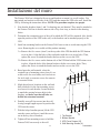
Installation de paroi
The Fortress.TeleCom is shipped with screws and brackets to mount it to a wall surface. You
must attach one bracket to each side of the UPS, and then mount the UPS to the wall. Install the
UPS by following the instructions below. NOTE: The procedure requires two people.
1.
Note that the brackets (items 1 and 2 in drawing) are not identical. They must be attached to
the Fortress.TeleCom so that the narrow side of key slots is up, as shown in the drawing
below.
2.
Determine the construction type of the wall to which the UPS will be mounted. Also, decide
upon the position of the UPS on the wall, so the brackets can be attached properly to the
UPS.
3.
Install one mounting bracket on the Fortress.TeleCom at a time to avoid removing the UPS
cover. Removing the cover could void the product warranty.
3.a. Remove the five screws (item 3) on the top side of the UPS that hold the UPS bottom
cover in place. Align the holes of the top bracket with the cover-screw holes. Then,
replace the screws to attach the bracket and secure the cover to the UPS.
3.b. Remove the five screws on the bottom side of the UPS that hold the UPS bottom cover
in place. Align the holes of the bottom bracket with the cover-screw holes. Then,
replace the screws to attach the bracket and secure the cover to the UPS.
4.
Based upon the wall material, select the
required type of mounting screws (item 4): use
wood screws for wood studs, steel stud screws
for steel studs, or concrete screws for concrete
or concrete blocks.
5.
Mark desired screw locations on the wall and
drill pilot holes for the four mounting screws:
two screws for each bracket. Locate the holes
to match the spacing between holes in the
brackets, and make sure that all holes are
drilled into structural material.
6.
Partially screw all four screws into the wall,
leaving enough length exposed to position the
UPS onto the screws.
7.
With the help of another person, lift the UPS
onto the screws and lower it until the screws
are in the key slots of brackets.
8.
Tighten all four mounting screws to hold the
Fortress.TeleCom securely to the wall.
31
3
1
2
4
1
2
3
4
Top Bracket
Bottom Bracket
UPS Cover Screws (10)
Wall Mounting Screws (4)
FRANÇAIS
Installation de châssis
Pour installer un Fortress.TeleCom dans un châssis standard 19" (483 mm) EIA 310 C, veuillez
suivre ces instructions.
Ne pas essayer de monter l'unité si le châssis est trop large.
1.
Installer une tablette fixe ou des consoles d'angle (disponibles comme matériel standard chez
les distributeurs électroniques) au-dessous de l'emplacement prévu du châssis pour le
Fortress.TeleCom. Fixer la tablette ou les consoles à l'avant et à l'arrière du châssis avec des
boulons, des écrous et des rondelles.
2.
Placer l'unité avec précaution sur la tablette ou les consoles et la faire glisser dans le châssis
comme indiqué ci-dessous. Les orifices de montage ménagés sur les côtés du tableau frontal
doivent s'ajuster aux trous dans le châssis.
3.
Utiliser des boulons et des rondelles pour fixer solidement l'unité au châssis.
FRANÇAIS
32
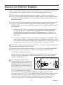
Démarrage rapide
1
2
Si votre UPS Fortress.TeleCom a un cordon d'alimentation amovible, Branchez le cordon à
l'arrière de l'appareil. Enfichez l'UPS dans une prise murale.
3
Nota : Le bouton Marche/Arrêt doit être enfoncé et tenu pendant environ une seconde pour
mettre l'appareil Fortress.TeleCom en marche ou arrêt. Pour démarrer l'appareil maintenant,
enfoncez et tenez le bouton Marche/Arrêt (le bouton du bas sur le panneau avant). Lorsque
l'appareil démarrera, il va :
Laissez l'appareil charger la batterie pendant au moins 3 heures (7 heures pour le modèle
1425 VA s'il est à pleine charge). Vous pouvez utiliser l'appareil pendant que la batterie se
charge, mais le temps de marche en secours de la batterie est réduit jusqu'à ce que la batterie
soit complètement chargée.
3.a.Faire un bip, puis allumer les lampes du panneau avant, les éteindre, et les allumer à
nouveau. Ensuite, le Fortress.TeleCom applique du courant alternatif aux réceptacles
du panneau arrière. Il fait ensuite un rapide auto-test, et allume et éteint les différentes
lampes du panneau avant.
3.b. Au bout de 30 secondes ou moins, l'auto-test se termine. Les lampes vertes du haut et du
bas s'allument et restent allumées. Si l'appareil fait un bip, ou si la lampe supérieure ne
reste pas allumée, bien que du courant d'alimentation soit disponible à la prise murale,
allez à la partie "Recherche de pannes".
4
5
Mettez hors tension le matériel que vous voulez protéger, et enfichez le dans les sorties à
l'arrière du Fortress.TeleCom.
Mettez sous tension le matériel protégé, un à la fois. Si l'UPS émet des bips lorsque vous
démarrez votre matériel, l'UPS est peut-être surchargé. Voir la section "Recherche de pannes".
Les quatre lampes du bas à l'avant de l'UPS indiquent le % de puissance de l'UPS que votre
matériel utilise. Voir la section "Symboles, Diodes et Bips sonores" pour avoir plus
d'informations.
6
750
1050, 1425, 1800 & 2250
Les jacks de protection contre les pointes
RJ-11 ou RJ-45 protègent le matériel qui
OUT
utilise une connexion RJ-11 ou RJ-45.
IN
OUT
IN
Enfichez la connexion de réseau
10BASE-T (ou à la ligne de téléphone,
fax ou modem pour les modèles U) dans
IN
OUT
le jack de protection contre les pointes
étiquetées "IN" à l'arrière du
Jacks RJ-11 ou RJ-45
Fortress.TeleCom. Enfichez le matériel
protégé dans le jack de protection contreles
pointes étiqueté "OUT". Le câblage au réseau n'est pas fourni. Réseau uniquement sur le
modèle européen; ne connectez pas de matériel TNV comme le téléphone, le fax ou un
modem sur les circuits. Il ne peut être utilisé que pour la protection de réseau, sur modèles E.
Cette connexion est en option. Elle n'est pas nécessaire pour utiliser le Fortress.TeleCom.
ou
33
FRANÇAIS
7
Veuillez remplir la carte d'enregistrement pour la garantie et la renvoyer à votre bureau local
de Best Power. Si vous êtes aux Etats-Unis ou au Canada et que vous désirez mettre en
service la garantie pour Suppression des pointes de tension transitoires, veuillez renvoyer la
carte d'enregistrement dans les 10 jours de l'installation.
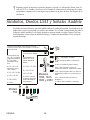
Symboles, Diodes et Bips sonores
Les diodes du panneau avant et un bip sonore indiquent le statut de l'appareil. L'appareil émet un
bip chaque fois qu'elle sur batterie ou s'il y a une alarme. Voir le Tableau 2 pour des informations
sur le codage de bips. Sur la figure ci-dessous, compensation signifie que Fortress.TeleCom
réduit la tension élevée d'entrée, et amplification signifie que Fortress.TeleCom augmente la
tension basse d'entrée.
Fixe: Fortress.TeleCom fonctionne sur le secteur alternatif
Clignotante: Fortress.TeleCom réduit ou augmente l'entrée
du secteur CA.
Fonctionnement sur
secteur CA: A, B, C
et D indiquent le
pourcentage de
pleine charge.
A, B, C et D, avec D
clignotant, charge =
110% ou plus.
Fixe: Fortress.TeleCom
fonctionne sur batteries
B, C et D = 50 - 75%
A, B et C = 50 - 75%
C et D = 25 - 50%
A = 0 - 25%
Modèle 750
D = 0 - 25%; lorsque
D clignote, il reste
moins de marche.
D
C
B
Clignotante = ETAT D'ALARME
C = Arrêt de l'UPS en raison de surcharge
C en sortie.
B = UPS n'a pas réussi le test de batterie.
A, B, C et D = 75 100%
A, B, C et D = 75 100%
A et B = 25 - 50%
D
Fonctionnement sur
batterie: A, B, C et D
indiquent la charge
de la batterie
B
B & C = Arrêt de l'UPS depuis la communication à RS-232, arrêt à distance ou SNMP.
A & B = Arrêt de l'UPS en raison d'une
A défaillance du relais principal ou court-circuit
Modèles 1050,
1425, 1800 et
2250
à la sortie.
A & C = Arrêt de l'UPS en raison de
surchauffe.
A = Défaut UPS; panne de ventilateur ou
surcharge.
A
Un voyant situé sur le panneau arrière des modèles Fortress.TeleCom U (appelé Avertissement
d'Anomalie du Site) s'allume pour indiquer un défaut de cablage dans le circuit auquel le
Fortress.TeleCom est connecté. Si ce voyant est allumé, la sortie doit être vérifiée et réparée par
un électricien. Ne pas utiliser cette sortie jusqu'à ce qu'elle soit réparée et déclarée conforme aux
normes de sécurité.
FRANÇAIS
34
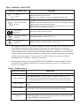
Tableau 1 : Symboles et Diodes
Symboles et Diodes
LIGNE CA
(Verte)
CORRECTION DE LIGNE
(Verte)
Ce que cela signifie
Fixe : Puissance d'entrée acceptable. L'appareil fonctionne sur
alimentation de ligne.
Eteinte : Pas d'alimentation à l'entrée ou l'appareil est hors tension.
Clignotement :L'appareil réduit ou amplifie la tension secteur.
Amplification = Augmente automatiquement une tension basse à
l'entrée pour empêcher l'appareil de passer sur batterie.
Réduction = Diminue automatiquement une tension élevée à l'entrée
pour empêcher l'appareil de passer sur batterie.
MODE BATTERIE
(Jaune)
L'appareil marche sur alimentation batterie.
SURCHARGE
(Diode D) (Jaune)
Surcharge en sortie : Voir les tableaux 2 et 3.
AVERTISSEMENT,
(Diode D) (Jaune)
Remplacer la batterie ou Défaut de l'UPS. Se référer aux tableaux 2
et 3.
Si votre Fortress.TeleCom marche souvent sur batterie parce que le courant secteur varie souvent,
vous pouvez vouloir adapter votre Fortress.TeleCom pour accepter des variations plus grandes de
tension avant le passage sur batteries. L'Annexe A décrit la manière d'ajuster le Fortress.TeleCom
par le panneau avant en réponse à des problèmes spécifiques au secteur. Vous devriez faire
vérifier votre tension nominale par un électricien pour déterminer si le problème est dû à une
tension de pointe ("Surge"/élevée) ou une baisse de tension "Brownout". Le changement du
réglage sans cette information peut faire empirer le problème.
Pour rendre une alarme silencieuse, appuyez sur le bouton ALARM SILENCE sur le panneau
avant. Le bip s'arrête, mais le voyant d'alarme reste allumé. Nota : La mise sous silence de
l'alarme ne résout pas le problème qui l'a causé. Voir Tableaux 2 et 3.
Tableau 2 : Bips sonores
Nombre de bips
Ce que cela signifie
1 toutes les 10 secondes Perte de ligne : L'appareil est sur batterie. Voir le tableau 3 pour plus d'informations.
Alarme batterie déchargée : L'appareil fonctionnait sur batterie et s'est arrêté en raison
2 toutes les 10 secondes d'une très faible tension de batterie. L'appareil redémarrera automatiquement lorsqu'une
tension acceptable reviendra.
3 toutes les 10 secondes
3 toutes les 5 minutes
1 bip par seconde
Continu
Remplacer la batterie : La batterie a besoin d'être remplacée. Voir "Remplacement des
batteries".
Batterie chargée insuffisamment : Au cours d'une connexion online, une faible tension de
la batterie indique qu'il reste une durée de sauvegarde minimum.
Surcharge en sortie : Trop de charge de matériel.
1) Court-circuit en sortie
2) Défaut au démarrage : Tension d'entrée hors limites lorsque l'appareil est mis sous tension.
3) Défaut UPS : Défaut interne de l'UPS.
35
FRANÇAIS
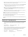
BestDock™
Le logement communication du BestDock du Fortress.TeleCom accepte des cartes de
communication en option, telles que l'adaptateur interne BestLink SNMP/WEB. L'insertion d'une
carte dans le logement de communication du BestDock remplace le canal normal de
communication sortant du port de communication DB-9 du Fortress.TeleCom. Le port DB-9
devient le point de branchement pour configurer la carte dans le BestDock.
Recherche de pannes
Si vous vous posez une question ou avez un problème, le tableau de recherches de pannes peut
être utile. (Voir le Tableau 3). Si vous avez besoin d'aide, téléphonez au Service International de
Best Power ou à votre bureau local de Best Power. Ayez sous la main le numéro de modèle et le
numéro de série (situé à l'arrière de l'appareil).
Si l'appareil doit être renvoyé, Best Power vous donnera un numéro d'Autorisation de retour de
matériels (RMA). Téléphonez à Best Power pour avoir un numéro de RMA avant de renvoyer
l'appareil pour quelle que raison que ce soit.
Tableau 3 : Recherche de pannes
Problème
Raisons possibles
Diode jaune de batterie allumée, 1. Coupure de courant secteur.
diode verte de ligne éteinte, un 2. Fiche desserrée.
bip toutes les 10 secondes.
3. Disjoncteur déclenché.
4. Panne de cordon
d'alimentation.
Diode jaune de batterie allumée, Très basse tension batterie.
diode verte de ligne éteinte,
deux bips toutes les 10 secondes.
Ce qu'il faut faire
1. Attendez que le courant soit rétabli.
2. Assurez-vous que le cordon d'alimentation est
branché.
3. Ré-enclenchez le disjoncteur.
4. Téléphonez au Service International de Best Power.
Enfichez l'appareil dans une prise murale en service,
pendant au moins 8 heures, pour permettre aux batteries
de se recharger. Après le rechargement, si l'appareil ne
fonctionne pas sur les batteries, ou si l'appareil fait deux
bips toutes les 10 secondes sur batteries, téléphonez au
Service International de Best Power.
Diode verte de ligne allumée,
diode jaune d'avertissement
allumée, trois bips toutes les 10
secondes.
Mettez l'appareil hors tension puis sous tension pour
remettre à zéro l'alarme et les diodes "Remplacez les
batteries". Remplacez les batteries. Voir "Remplacement
des batteries".
L'appareil n'a pas passé le
test des batteries.
Diode verte de ligne allumée, diode La batterie n'est pas chargée Utiliser le chargeur branché au secteur; attendre le
jaune d'avertissement éteinte, trois en raison d'une panne de
rechargement complet. Les bips s'arrêtent
bips toutes les 5 minutes.
courant.*
automatiquement lorsque la batterie est chargée.
Diode jaune de surcharge est
clignotante, un bip toutes les
secondes.
La puissance demandée par 1. Retirez le matériel en charge.
le matériel est trop élevée. 2. Réduisez le niveau de la charge jusqu'à ce que les
bips s'arrêtent.
Diode jaune d'avertissement
allumée. Bip continu.
1. Court-circuit en sortie.
2. Défaut de UPS
1. Retirez la charge et remettez l'UPS à zéro.
2. Téléphonez au Service International de Best Power.
* Si Fortress.TeleCom ne peut pas charger la batterie après 24 heures avec un état d'alarme de 3 bips par 5 minutes, l'alarme
passera à 3 bips par 10 secondes, ce qui indique qu'il faut remplacer la batterie.
FRANÇAIS
36
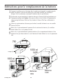
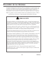
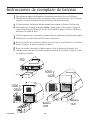
Remplacement des batteries
Les batteries du Fortress.TeleCom sont remplaçables par l'utilisateur et peuvent l'être pendant que
l'entrée du Fortress.TeleCom est sous tension et qu'il alimente les charges. Ceci signifie que, si
nécessaire, vous pouvez remplacer les batteries pendant que l'UPS fonctionne. Avant de remplacer
les batteries, n'oubliez pas de lire les informations ci-dessous sur la sécurité.
Nota : Si vous avez une coupure de courant pendant que vous remplacez les batteries, l'UPS ne
pourra pas fonctionner sur l'énergie des batteries et le matériel que vous protégez s'arrête.
ATTENTION
Les batteries utilisées dans l'UPS et la batterie de piles peuvent produire une tension
dangereuse et un courant élevé. Donc les batteries peuvent provoquer de graves blessures si
leurs bornes touchent un outil ou l'armoire de l'UPS. Faites très attention d'éviter des
décharges électriques et des brûlures par le contact avec les bornes pendant que vous
remplacez les batteries.
Les batteries contiennent des acides corrosifs et des matières toxiques et peuvent se rompre
ou fuir si elles sont maltraitées. Retirez les bagues et les montres bracelets métalliques ou
autres bijoux. Ne portez pas d'objets métalliques dans vos poches : ces objets pourraient
tomber dans l'UPS.
Ne laissez jamais un outil toucher à la fois une borne de batterie et l'armoire de l'UPS ou une
autre borne de batterie. Ne posez pas d'outils ou de pièces métalliques sur les batteries.
Pour assurer des performances continuellement supérieures de votre UPS et pour garder un
fonctionnent correct de chargeur, vous devez remplacer les batteries UPS avec le même
nombre et type de batteries. Ces batteries doivent être du même type que les batteries
originales : régulées, faible entretien. Les batteries de remplacement doivent avoir les mêmes
valeurs nominales de tension et d'ampère-heure que le batteries originales.
Supposez que les anciennes batteries sont à pleine charge. Prenez les mêmes précautions que
lorsque vous manipulez un batterie neuve. Ne court-circuitez pas les bornes de batterie avec
un câble ou un outil ! Les batteries contiennent du plomb. De nombreux endroits ont des
règlements sur le rejet de vieilles batteries. Jetez les correctement. NE JETEZ PAS de
batteries dans le feu car elles pourraient exploser. N'ouvrez pas et ne mutilez pas les batteries.
L'électrolyte libéré est nocif pour la peau et pour les yeux. Il peut être toxique.
Ce matériel peut produire de l'ozone. Prenez des précautions pour assurer que la
concentration d'ozone est limitée à une valeur de sécurité (0,1 ppm {0,2 mg/m 3} calculée
comme la moyenne pesée sur une période de 8 heures).
37
FRANÇAIS
Instructions pour le remplacement de la batterie
1
Contacter le meilleur service électrique dans le monde pour demander le remplacement du
module de batterie. Il doit être du même type et puissance nominale que les batteries
d'origine. Voir les indications concernant les batteries dans les spécifications.
2
Si nécessaire, on peut remplacer les batteries alors que le Fortress.TeleCom fonctionne avec
l'équipement protégé joint. Option: Vous pouvez arrêter et tirer la fiche de l'équipement de
charge protégé du Fortress.TeleCom. Puis, éteindre le Fortress.TeleCom et débrancher le
cordon.
3
4
5
Utiliser les représentations ci-dessous pour localiser le module de batterie sur votre modèle
Fortress.TeleCom.
Enlever les vis qui maintiennent le panneau d'accès extérieur des batteries (1) au tableau
frontal. Mettre les vis et le panneau de côté.
Enlever les vis qui maintiennent le panneau intérieur (2) au compartiment de batterie. Faire
attention de ne pas laisser tomber les vis à l'intérieur de l'unité. Mettre les vis et le panneau de
côté.
2
1
750
noir (-)
1050 et
1425
rouge (+)
1800 et
2250
2
1
2
1
noir (-)
rouge (+)
Batteries
1050
FRANÇAIS
38
Batteries
1425
6
7
Utiliser les pattes fixées sur les batteries pour les enlever du Fortress.TeleCom. Ne pas
extraire lesbatteries en tirant les bornes ou les câbles.
8
Rebrancher les câbles sur le nouveau module de batterie, le rouge sur la borne positive (+), le
noir sur la borne négative (-). Pour les modèles 1800 et 2250: Enficher le câble de batterie
dans la connexion de l'unité.
9
10
11
12
Débrancher les câbles rouge et noir du module de batterie usagé. Pour les modèles 1800 et
2250: Débrancher la fiche de batterie de la connexion de câble dans l'unité. Disposer
correctement des vieilles batteries.
Placer les câbles de batterie en évitant de les coincer entre le panneau intérieur ou le module
de batterie. Faire glisser le module dans l'unité.
Utiliser les vis enlevées précédemment pour fixer de nouveau le panneau intérieur sur le
compartiment de batterie et le panneau extérieur au tableau frontal.
Si vous avez suivi l'option de l'étape 2: Rebrancher le cordon d'alimentation au
Fortress.TeleCom et mettre en marche l'unité.
Rebrancher l'équipement de charge. Allumer l'équipement d'un seul coup.
Port de communication
Le Fortress.TeleCom est compatible avec Windows 95 pour utilisation immédiate.
Le Fortress.TeleCom est équipé de logiciel de gestion CheckUPS II. Un câble d'interface est
prévu pour les systèmes suivants :
SCO UNIX/XENIX
Windows 3.X, 95 ou NT
UNIX et systèmes compatibles
Novell NetWare
OS/2
Best Power offre des kits d'interface qui vous permettent de brancher de nombreux autres systèmes
informatiques sur le port de communication du Fortress.TeleCom. Pour les systèmes informatiques
suivants, ou pour des renseignements spécifiques sur les kits d'interface de Best Power, appelez le
Service International de Best Power ou votre revendeur local de Best Power.
Banyan VINES
Lantastic v4.0
IBM RS/6000 AIX
Gestionnaire/Serveur LAN v2.0
39
IBM AS/400 spécial
FRANÇAIS
Brochage de DB-9
Broche 1
Broche 2
Broche 3
Broche 4
Broche 5
Broche 6
Broche 7
Broche 8
Broche 9
RS232 Réception de données : Reçoit les données de communication RS232 entrantes.
RS232 Emission de données : Envoie les données de communication RS232 sortantes.
Contact normalement ouvert sur batterie : Contact normalement ouvert qui se ferme
15 secondes (revient à Commun) après que l'UPS passe sur alimentation par batteries.
Commun : La terre de signal pour toutes les broches de signal.
Contact normalement ouvert d'alarme de Batterie Déchargée : Contact normalement
ouvert qui se ferme (revient à Commun) pendant une alarme de Batterie Déchargée. Ceci
dit à CheckUPS II et autre logiciel d'arrêt quand il faut commencer un arrêt d'ordinateur.
Détection d'utilisation immédiate pour Windows 95.
Arrêt à distance : Si on court-circuite cette broche avec Commun pendant au moins
5 secondes pendant que l'UPS fonctionne sur batteries, on met l'UPS hors tension au bout
de 120 secondes.
Contact normalement fermé sur batterie : Contact normalement fermé qui s'ouvre
15 secondes (libéré de Commun) après que l'UPS passe sur alimentation par batteries.
Inutilisée.
Les contacts consistent en des circuits à collecteur ouvert capables de commuter une charge
résistive jusqu'à +30 V CC, 6 mA.
Spécifications
Best Power se réserve le droit de changer les spécifications sans préavis.
Protection contre les transitoires du secteur : Passe le test ANSI/IEEE C62.41 Catégorie A.
Conformité à la sécurité :
Modèle U : Testé selon UL1449; Classé UL1778 et CAN/CSA C22.2 N° 107.1 M91.
Modèle E : Classé TÜV/GS.
Conformité avec Compatibilité électromagnétique :
Modèle U : FCC Classe A; sauf le modèle 750 VA qui est conforme à FCC Classe B.
Modèle E: CISPR 22 Classe B, Vfg 243-91/46-92B, EN55022, Marque CE auto-certifié.
selon : Directive CE sur le marquage 93/68/EEC, Directive basse tension 72/23/EEC.
Elimination du bruit (HF) : Filtrage constant EMI/RFI.
Rendement : >95% en ligne.
Capacité VA/Watts : 750 VA/450 W; 1050 VA/670 W; 1425 VA/95 W; 1800 VA/1260 W, 2250 VA/1600 W.
Tension nominale : Modèle U : 120 V CA, Modèle E : 230 V CA.
Gamme de tension :Modèle U : 0 à 160 V CA, fonctionnant sur batterie et amplification/réduction; 96 à
146 V CA fonctionnant uniquement en amplification/réduction.
Modèle E : 0 à 300 V CA, fonctionnant sur batterie et amplification/réduction; 188 à
270 V CA fonctionnant uniquement en amplification/réduction.
Fréquence : 50/60 Hz auto détection 55 - 65 Hz (60 Hz); 45 - 55 Hz (50 Hz) (50/60 Hz ±0,5 Hz sur batterie).
Temps minimum de marche (minutes) :
Modèles 750, 1050 et 1425 VA : Pleine charge : 6,5 minutes. Demi-charge : 15 minutes.
Modeles 1800 VA : Pleine charge : 7,5 minutes. Demi-charge : 22 minutes.
Modèles 2250 VA : Pleine charge : 5 minutes. Demi-charge : 12 minutes.
FRANÇAIS
40
Temps de transfert : Typiquement 4 ms.
Suppression des pointes sur ligne téléphonique pour les modèles U : selon Bellcore 1089 : forme d'onde
1,2/50 ms, ±2 kV de pointe, conforme à
UL497A.
Indicateur de défaut de câblage sur site pour les modèles U :Diode sur panneau arrière indique un défaut
d'inversion de phase sur la ligne d'entrée secteur.
Batterie : Etanche, sans entretien, régulée, reconnue comme UL 924.
Modèles 750 VA :
Deux batteries de 12 V, 9,0 AH. Tension nominale 24 V CC.
Modèles 1050 VA :
Trois batteries de 12 V 9,0 AH. Tension nominale 36 V CC.
Modèles 1425 VA :
Quatre batteries de 12 V 9,0 AH. Tension nominale 48 V CC.
Modèles 1800/2250 VA :
Huit batteries de 6 V, 12,0 AH. Tension nominale 48 V CC.
Test automatique de batterie :Le test automatique de batterie a lieu au démarrage et tous les 14 jours ensuite.
Une alarme résonne si la batterie ne passe pas le test.
Temps de recharge de batterie :
(à 95% de la capacité)
750 VA, 1050 VA, 1425 VA, 1800 VA et 2250 VA : 3 heures.
1425 VA : 7 heures avec sortie à pleine charge. Le temps de recharge est
inférieur avec une charge réduite.
Protection contre surintensité (en ligne) : Tous les modèles : Disjoncteur.
Courant de défaut entrée (maximum): Modèles 750E et 1050E: 15 A.Modèle 1425E: 26.1 A
Modèle 2250E: 35 A.
Informations sur l'entrée CA fiche/cordon :
750 U - NEMA 5-15P; cordon attaché.
1050 U - NEMA 5-15P; cordon attaché.
1425 U - NEMA 5-15P; cordon attaché.
1800 U - NEMA 5-20P; cordon attaché.
2250 U - NEMA L5-30P; cordon attaché.
Répartition des sorties CA :
750 U - (6) NEMA 5-15R.
1050 U - (6) NEMA 5-15R.
1425 U - (6) NEMA 5-15R.
1800 U - (4) NEMA 5-15R, (2) NEMA 5-20R.
2250 U - (4) NEMA 5-15R, (2) NEMA 5-20R,
(1) NEMA L5-30R.
750 E - CEE 22, fiche encastrée.
1050 E - CEE 22, fiche encastrée.
1425 E - CEE 22, fiche encastrée.
2250 E - CEE 19, fiche encastrée.
750 E - (4) CEE 22.
1050 E - (4) CEE 22.
1425 E - (4) CEE 22.
2250 E - (4) CEE 22, (1) CEE 19.
Compatibilité des charges : Peut accepter un facteur de puissance amélioré de 100%, charge secteur en mode
commutation.
Bruit audible : < 45 dBa à un mètre, sauf le modèle 1800/2250 qui est à < 55 dBa à un mètre.
Ventilation : L'air autour de l'appareil ne doit contenir aucune poussière, produits chimiques, ou autres
matières corrosives ou contaminantes. L'air doit circuler librement autour de l'appareil.
Température de fonctionnement : 32° - 104° F (0° - 40°C)
Température de stockage : 5° - 122° F (-15°C à +50°C) La durée des batteries est réduite au dessus
de 77° F (25°C).
Si l'appareil Fortress.TeleCom est mis en stock, les batteries doivent être
rechargées tous les 6 mois. S'il est stocké à plus de 77° F (25°C), il faut recharger
les batteries plus souvent.
Humidité :
5% - 95% HR (sans condensation).
41
FRANÇAIS
Dimensions (hauteur x largeur x longueur): 750 VA
1050/1425 VA :
1800/2250 VA :
Poids :
750 VA :
1050 VA :
1425 VA :
1800/2250 VA :
39,6 lb
51,3 lb
57,2 lb
86,0 lb
3,5 x 17,6 x 18,7 " (88 x 448 x 475 mm)
5,3 x 17,6 x 18,7 " (133 x 448 x 475 mm)
7,0 x 17,6 x 18,7 " (178 x 448 x 475 mm)
(18,0 kg),
(23,3 kg),
(26,0 kg),
(39,1 kg).
Garantie
GARANTIE LIMITEE DE DEUX ANS
Garantie standard pour tous les achats
Best Power, division de SPX Corporation, (ci-après appelée BEST POWER) garantit que chaque produit
vendu par BEST POWER est compatible avec le matériel informatique actuellement dans le commerce avec
alimentation électrique incluse et ne comporte pas de défauts de matière et main d'oeuvre dans les
conditions normales d'utilisation et de service. Cette garantie ne s'applique qu'à l'acheteur initial au détail
(ACHETEUR), et n'est pas transférable.
La durée de cette garantie est de deux (2) ans à partir de la date de la première vente au détail ou de la date
de livraison à l'ACHETEUR, la première des deux, sous réserve des conditions suivantes.
Si l'ACHETEUR découvre, pendant la période de cette garantie, le non fonctionnement du produit de
manière compatible avec le matériel informatique existant ou un défaut de matière ou main d'oeuvre,
l'ACHETEUR doit immédiatement aviser BEST POWER par écrit pendant la durée de la garantie, ou au
plus tard un mois après l'expiration de la garantie. La responsabilité de BEST POWER dans le cadre de
cette garantie est limitée au remplacement ou à la réparation, sous réserve des conditions spécifiées cidessous, du produit renvoyé intact à BEST POWER qui devra se montrer à BEST POWER, suite à examen,
avoir été incompatible ou défectueux. Le remplacement ou la réparation sera fait au Worldwide Service de
BEST POWER, Highway 80, Necedah, Wisconsin 54646, Etats-Unis. Cette réparation ou ce remplacement
seront aux frais de BEST POWER. La présente garantie ne couvre pas des taxes qui pourront être dues en
rapport avec le remplacement ou la réparation, ni des frais d'installation, retrait, transport ou postaux. Ces
frais seront payés par l'ACHETEUR. Si BEST POWER est incapable de réparer ou remplacer le produit
pour se conformer à la présente garantie après un nombre raisonnable d'essais, BEST POWER remboursera
le prix d'achat. Les compensations dans le cadre de la présente garantie sont expressément limitées à celles
spécifiées ci-dessus.
DANS LA MESURE OU CELA EST AUTORISE PAR LA LOI, BEST POWER REFUSE TOUTES
AUTRES GARANTIES, EXPRESSES OU SOUS-ENTENDUES, Y COMPRIS, MAIS SANS Y ETRE
LIMITE, DES GARANTIES SOUS-ENTENDUES DE POSSIBILITE DE COMMERCIALISATION OU
DE REPONSE A UN BUT PARTICULIER, ET TOUTE GARANTIE SOUS-ENTENDUE DE
POSSIBILITE DE COMMERCIALISATION OU DE REPONSE A UN BUT PARTICULIER
CONCERNANT CE PRODUIT EST LIMITEE EN DUREE A LA DUREE DE LA PRESENTE
GARANTIE. DANS LA MESURE OU CELA EST AUTORISE PAR LA LOI, BEST POWER NE
POURRA ETRE RESPONSABLE DE DEGATS SPECIAUX, ACCIDENTELS, OU CONSECUTIFS, Y
COMPRIS, MAIS SANS Y ETRE LIMITE, A LA PERTE DE BENEFICES, DES DOMMAGES AUX
BIENS, LA PERTE DE L'USAGE DU PRODUIT OU DE TOUT MATERIEL ASSOCIE.
Certains états ne permettent pas de limitations sur la durée d'une garantie sous-entendue, et donc la
limitation de durée des garanties sous-entendues peut ne pas s'appliquer à vous. Certains états ne permettent
pas l'exclusion ou la limitation de dommages accidentels ou consécutifs, et donc la limitation ou l'exclusion
FRANÇAIS
42
ci-dessus peut ne pas s'appliquer à vous. La présente garantie vous donne des droits légaux spécifiques, et
vous pouvez avoir aussi d'autres droits qui peuvent varier d'un état à l'autre. Il vous est conseillé de
consulter les lois nationales applicables.
Aucune garantie n'est donnée concernant d'autres produits vendus par BEST POWER, qui ne portent pas le
nom de BEST POWER, et aucune recommandation de ces autres produits ne pourra sous-entendre ou
constituer une garantie en ce qui les concerne. La présente garantie ne couvre pas la réparation ou le
remplacement dû à des dommages causés par une utilisation déraisonnable (à titre d'exemple
uniquement - des dommages provenant de risques routiers, d'accidents, d'incendie ou autre victime,
mauvaise utilisation, négligence, ou câblage incorrect) et par l'utilisation ou l'installation non conforme aux
instructions fournies par BEST POWER, ni les réparations ou les remplacements nécessaires en raison de
modifications ou de pièces non autorisées ou fournies par BEST POWER.
GARANTIE LIMITEE
Circuits d'élimination de surtensions transitoires
(Uniquement pour les Acheteurs Américains et Canadiens)
BEST POWER, division de SPX Corporation, ("BEST POWER") garantit par les présentes que les circuits
d'élimination de surtensions transitoires dans chaque produit FERRUPS®, FORTRESS®,
FORTRESS.TeleCom™, PATRIOT®, UNITY/I®, CITADEL®, ou SPIKEFREE™ (ci-après appelés
"Produit") vendu par BEST POWER pour installation aux Etats-Unis d'Amérique et au Canada ne comporte
aucun défaut de matière ou main d'oeuvre en utilisation et entretien normaux pendant la durée de vie du
Produit, à partir de la date de vente à l'acheteur initial au détail, sous réserve des conditions suivantes.
La présente garantie ne s'applique qu'à l'acheteur initial au détail (ci-après appelé ACHETEUR), n'est pas
transférable, et est limitée aux compensations suivantes :
1.
Remplacement ou réparation des circuits d'élimination de surtensions transitoires dans
chaque Produit renvoyé intact à BEST POWER et qui semblera à BEST POWER, après examen,
avoir été défectueux en matière ou main d'oeuvre ou avoir été endommagé par une utilisation
normale;
2.
Le remboursement à l'ACHETEUR d'un maximum de US$25.000 par occurrence de dommages
physiquement documentés à du matériel informatique spécifié relié à un Produit, lorsque ces dom
mages pourraient avoir été évités par les circuits d'élimination de surtensions transitoires tels que
décrits dans la spécification de BEST POWER pour le Produit vendu.
La présente garantie est donnée en supplément de la Garantie limitée de deux ans de BEST POWER.
La présente garantie n'inclut pas de taxes qui pourront être dues en rapport avec le remplacement ou la ré
paration, ni des frais d'installation, transport ou postaux. Ces frais seront payés par l'ACHETEUR. Le
remplacement ou la réparation sera fait au Worldwide Service de BEST POWER, Highway 80, Necedah,
Wisconsin 54646, Etats-Unis.
La présente garantie ne couvre pas la réparation ou le remplacement dû à des dommages causés par une
utilisation déraisonnable (dommages provenant de risques routiers, d'accidents, d'incendie ou autre victime,
mauvaise utilisation, négligence, câblage incorrect) et par l'utilisation ou l'installation non conforme aux
instructions fournies par BEST POWER, ni les réparations ou les remplacements nécessaires en raison de
modifications ou de pièces non autorisées ou fournies par BEST POWER.
43
FRANÇAIS
La présente garantie est valable après acceptation écrite par BEST POWER d'une demande de
l'ACHETEUR sur formulaire standard de BEST POWER pour la couverture de garantie ci-dessus du
Produit vendu. Dans cette demande, l'ACHETEUR doit expliquer que le Produit vendu a été correctement
installé et mis à la terre conformément aux instructions reçues de BEST POWER, et l'ACHETEUR doit
aussi spécifier le matériel informatique auquel le Produit vendu a été relié et l'emplacement du matériel
informatique. Cette garantie ne s'applique pas à du matériel non spécifié, dans la demande par
l'ACHETEUR, comme matériel protégé.
SAUF SI CELA EST PRECISE CLAIREMENT DANS LA PRESENTE GARANTIE ET LA GARANTIE
LIMITEE DE DEUX ANS DE BEST POWER, BEST POWER NE DONNE AUCUNE AUTRE
GARANTIE? ET DANS LA MESURE OU CELA EST AUTORISE PAR LA LOI, BEST POWER
REFUSE TOUTES AUTRES GARANTIES, EXPRESSES OU SOUS-ENTENDUES, Y COMPRIS, MAIS
SANS Y ETRE LIMITE, DES GARANTIES SOUS-ENTENDUES DE POSSIBILITE DE
COMMERCIALISATION OU DE REPONSE A UN BUT PARTICULIER, ET TOUTE GARANTIE
SOUS ENTENDUE DE POSSIBILITE DE COMMERCIALISATION OU DE REPONSE A UN BUT
PARTICULIER.
LES COMPENSATIONS DANS LE CADRE DE LA PRESENTE GARANTIE SONT EXPRESSEMENT
LIMITEES A LA REPARATION OU AU REMPLACEMENT DES PRODUITS ET AU
REMBOURSEMENT SPECIFIE CI-DESSUS, ET, DANS LA MESURE OU CELA EST AUTORISE PAR
LA LOI, TOUTE RECLAMATION POUR DES PERTES CAUSEES PAR LA NON PERFORMANCE
DES PRODUITS PENDANT UNE PERIODE, OU DES DOMMAGES SPECIAUX, INDIRECTS,
ACCIDENTELS, OU CONSECUTIFS OU AUTRE PERTE ECONOMIQUE, EST EXPRESSEMENT
EXCLUE.
Certains états ne permettent pas de limitations sur la durée d'une garantie sous-entendue, et donc la
limitation de durée des garanties sous-entendues peut ne pas s'appliquer à vous. Certains états ne permettent
pas l'exclusion ou la limitation de dommages accidentels ou consécutifs, et donc la limitation ou l'exclusion
ci-dessus peut ne pas s'appliquer à vous. La présente garantie vous donne des droits légaux spécifiques, et
vous pouvez avoir aussi d'autres droits qui peuvent varier d'un état à l'autre. Il vous est conseillé de
consulter les lois nationales applicables.
FRANÇAIS
44
Bureaux de Best Power
Best Power
P.O. Box 280
Necedah, Wisconsin 54646 E-U
Téléphone: +1 608 565 7200
Appel gratuit : +1 800 356 5794 (E-U et Canada)
FAX: +1 608 565 2221
FAX International: +1 608 565 7675
Best Power Technology Mexico, S.A. de C.V.
Golfo de Riga, 34
Colonia Tacuba
México D.F. 11410
MÉXIQUE
Téléphone: +52 5 527 8009
Appel gratuit : +1 800 711 8978
FAX: +52 5 399 1320
Best Power Technology Limited
BEST House
Wykeham Industrial Estate
Moorside Road
Winchester
Hampshire
SO23 7RX
ANGLETERRE
Téléphone: +44 1962 844414
Appel gratuit: 0800 378444(Royaume-uni)
FAX: +44 1962-841846
Best Power Technology Germany GmbH
Am Weichselgarten 23
D-91058 Erlangen
ALLEMAGNE
Téléphone: +49 9131 77700
Appel gratuit: 0130 84 7712 (Allemagne)
FAX: +49 9131 7770 444
Best Power Technology, Pte. Ltd.
19 Neyhal Road
SINGAPOUR 628584
Téléphone: +65 265 6866
FAX: +65 265 6636
Borri Elettronica Industriale Srl
Via de Lavoratori, 124
20092 Cinisello Balsamo (Mi)
Milan, ITALIE
Téléphone +39 2 6600661 2
FAX: +39 2 6122481
Sola Australia Ltd.
13 Healey Road
Dandenong Victoria 3175
AUSTRALIE
Téléphone: +61 3 9706 5022
FAX: +61 3 9794 9150
45
FRANÇAIS
Annexe A: Ajustage des réglages de tension
Lorsque l'appareil ne sonne pas une alarme, vous pouvez utiliser le bouton illustré ci-dessous pour
changer ce qui suit :
· Tension nominale - Tension normale que l'UPS est programmé d'attendre, et tension nominale de sortie
d'UPS en cas de perte dans la ligne.
· Réduction - Tension d'entrée à laquelle le Fortress.TeleCom réduit la tension avant de fournir la sortie
parce que la tension d'entrée est trop élevée.
· Amplification - Tension d'entrée à laquelle le Fortress.TeleCom augmente la tension avant de fournir la
sortie parce que la tension d'entrée est trop basse.
· Transfert à l'onduleur - Point auquel l'UPS commute sur onduleur (alimentation par batterie), soit parce
que la tension alternative d'entrée est très basse, soit parce qu'elle est très haute.
Nota : Soyez sûr que vous voulez changer ces valeurs avant de démarrer la procédure ci-dessous. Une
fois que vous appuyez sur le bouton pendant 10 secondes, les valeurs changent aux valeurs
par défaut, et tout changement précédent que vous avez fait est perdu. Si vous désirez poser
une question, contactez le bureau de Best Power le plus proche, ou appelez Worldwide Service
au +1 800 356 5737 ou +1 608 565 2100.
Ne changez pas les réglages de tension lorsque l'appareilfonctionne sur l'onduleur. Pour changer ces
valeurs, suivez les étapes ci-après :
1.
Appuyez sur le bouton illustré jusqu'à ce que les diodes sur l'avant
du Fortress.TeleCom clignotent. Après le clignotement, trois restent
allumées et le Fortress.TeleCom émet un bip pendant une seconde.
2.
Les diodes qui sont allumées indiquent les réglages de tension qui
sont sélectionnés. Les diodes sont numérotées sur le dessin
ci-dessous pour vous aider à les identifier. Les tableaux 4 et 5
indiquent les réglages de tension pour chaque combinaison possible
de diodes.
Appuyez sur
cebouton
pendant 10
secondes
(jusqu'à ce
que toutes les
lampes
clignotent).
Par exemple, par défaut, les diodes 2, 3 et 4 sont allumées (voir le schéma). Si votre UPS est un
modèle U, vous trouverez cette ombinaison de diodes dans la première rangée du tableau 4. Cette
rangée indique ce qui suit :
1
1
• Avec 96 V d'entrée ou moins, le Fortress.TeleCom passe sur
2
2
l'alimentation batterie.
• Lorsque la tension à l'entrée tombe à 109, le Fortress.TeleCom
3
3
commence à augmenter la tension de sortie.
(D)
• 120 is the nominal or expected input voltage.
4
4
(C)
• 120 est la tension d'entrée nominale ou attendue.
5
• Lorsque la tension à l'entrée monte à 130, le Fortress.TeleCom 5
(B)
commence à augmenter la tension de sortie.
6
6
• Avec une tension à l'entrée de 146 volts ou plus, le
(A)
Fortress.TeleCom passe sur alimentation batterie.
Numéro des
Réglage par
diodes
FRANÇAIS
46
défaut
3.
4.
Utilisez le tableau approprié de la page suivante pour décider
de quelle combinaison de réglages vous avez besoin; notez
quelles diodes doivent s'allumer pour cette combinaison. Puis,
appuyez sur le bouton illustré brièvement (pendant environ
1 seconde) pour passer à la ombinaison suivante de diodes. Si
vous tenez le bouton appuyé pendant plus de 10 secondes,
le Fortress.TeleCom sauvegarde le réglage qui est affiché.
Continuez à appuyer sur le bouton jusqu'à ce que les diodes
correctes soient allumées.
Une fois les diodes correctes allumées, continuez à tenir le
bouton pendant 10 secondes pour sauvegarder vos
changements. Si le Fortress.TeleCom est en marche dur
l'alimentation secteur CA, l'affichage revient au pourcentage
de pleine charge. Les nouvelles valeurs deviennent effectives
après le retour de l'affichage au mode normal.
47
Appuyez sur ce
bouton
BRIEVEMENT
pourfaire défiler
les réglages.
Appuyez sur ce
bouton pendant
10 SECONDES
pour sauvegarder
vos changements.
FRANÇAIS
Tableau 4 : Réglages de tension pour les modèles U
Diodes
allumées
Vers l'onduleur Amplifica(Entrée CA basse)
tion
Tension
nominale
Réduction
Vers l'onduleur
(Entrée CA élevée)
2, 3, 4
(Par défaut)
96
109
120
130
146
1, 3, 4
96
109
120
138
156
2, 3, 5
90
104
120
130
146
1, 3, 5
90
104
120
138
156
3, 4, 5
90
104
110
120
130
2, 4, 5
90
104
110
130
146
3, 4, 6
90
96
110
120
130
2, 4, 6
90
96
110
130
146
1, 2, 4
96
109
128
146
156
1, 2, 5
90
104
128
146
156
Tension
nominale
Réduction
Vers l'onduleur
(Entrée CA élevée)
Tableau 5 : Réglages de tension pour les modèles E
Diodes
allumées
Vers l'onduleur Amplifica(Entrée CA basse)
tion
2, 3, 4
200
222
240
250
284
1, 3, 4
200
222
240
264
290
2, 3, 5
188
210
240
250
284
1, 3, 5
188
210
240
264
290
3, 4, 5
(Par défaut)
188
210
230
244
270
2, 4, 5
188
210
230
250
284
3, 4, 6
180
200
230
244
270
2, 4, 6
180
200
230
250
284
4, 5, 6
165
188
208
222
244
3, 5, 6
165
188
208
244
270
FRANÇAIS
48
Uniquement pour les utilisateurs au Canada :
Pour le Modèle U 750 VA
Ce matériel de Classe B générateur de parasites répond à toutes les exigences des Règlements Canadiens sur
le Matériel Générateur de Parasites ICES-003.
Pour les Modèles 1050, 1425, 1800 et 2250 VA
Ce matériel de Classe A générateur de parasites répond à toutes les exigences des Règlements Canadiens
sur le Matériel Générateur de Parasites ICES-003.
49
FRANÇAIS
Sie haben eine Frage?
Best Power ist bestrebt, einen hervorragenden Kundendienst zu bieten. Der weltweite
Kundendienst hilft Ihnen gerne bei Problemen und Fragen. Ein Kundendiensttechniker steht an
365 Tagen im Jahr rund um die Uhr zur Verfügung. Rufen Sie einfach Ihre nächstgelegene Best
Power-Niederlassung an oder senden Sie ein Telefax an den weltweiten Kundendienst. Bitte
halten Sie bei Anruf die Seriennummer Ihres Gerätes bereit; diese befindet sich auf der
Rückseite des Geräts.
Sie können stattdessen auch Best im World Wide Web aufsuchen, um weitere
Produktinformationen zu erhalten.
Der gebührenfreie Faxabrufservice von Best ist ebenfalls rund um die Uhr verfügbar, um Ihnen
Zugang zu technischen Unterlagen und Produktinformationen zu geben.
Kundendienst: Erlangen
.....Weltweiter Kundendienst:
.....Weltweiter Kundendienst-FAX:
.....World Wide Web-Seite:
............
.....Faxabruf - Verkauf:
.....Faxabruf - Kundendienst:
0180 5313495
1-800-356-5737 (USA, Kanada) oder 1-608-565-2100
1-608-565-7642 oder 1-608-565-2509
http://www.bestpower.de
http://www.bestpower.com
1-800-487-6813 (USA und Kanada)
1-608-565-9499, Durchwahl 9000
Auf der Seite 'Best Power-Niederlassungen' (siehe Inhaltsverzeichnis) sind die weltweiten Best
Power-Niederlassungen angeführt.
Best Power behält sich das Recht vor, technische Daten ohne Ankündigung zu ändern.
DEUTSCH
50
Inhaltsverzeichnis
Sie haben eine Frage? . . . . . . . . . . . . . . . . . . . . . . . . . . . . . . . . . . . . . . . . . . . . . . . . .50
Sicherheitshinweise . . . . . . . . . . . . . . . . . . . . . . . . . . . . . . . . . . . . . . . . . . . . . . . . . . .52
Eigenschaften der USV . . . . . . . . . . . . . . . . . . . . . . . . . . . . . . . . . . . . . . . . . . . . . . . .53
Wandmontage . . . . . . . . . . . . . . . . . . . . . . . . . . . . . . . . . . . . . . . . . . . . . . . . . . . . . . .55
Schrankeinbau . . . . . . . . . . . . . . . . . . . . . . . . . . . . . . . . . . . . . . . . . . . . . . . . . . . . . . .56
Schnellstart . . . . . . . . . . . . . . . . . . . . . . . . . . . . . . . . . . . . . . . . . . . . . . . . . . . . . . . . .57
Symbole, LEDs und Warntöne . . . . . . . . . . . . . . . . . . . . . . . . . . . . . . . . . . . . . . . . . .58
BestDocktm . . . . . . . . . . . . . . . . . . . . . . . . . . . . . . . . . . . . . . . . . . . . . . . . . . . . . . . . .60
Fehlersuche . . . . . . . . . . . . . . . . . . . . . . . . . . . . . . . . . . . . . . . . . . . . . . . . . . . . . . . . .60
Auswechseln der Batterien . . . . . . . . . . . . . . . . . . . . . . . . . . . . . . . . . . . . . . . . . . . . .61
Wechseln der Batterie . . . . . . . . . . . . . . . . . . . . . . . . . . . . . . . . . . . . . . . . . . . . . .62
Kommunikationsanschluß . . . . . . . . . . . . . . . . . . . . . . . . . . . . . . . . . . . . . . . . . . . . . .63
Anschlußbelegung DB-9 . . . . . . . . . . . . . . . . . . . . . . . . . . . . . . . . . . . . . . . . . . .64
Technische Daten . . . . . . . . . . . . . . . . . . . . . . . . . . . . . . . . . . . . . . . . . . . . . . . . . . . .64
Gewährleistung . . . . . . . . . . . . . . . . . . . . . . . . . . . . . . . . . . . . . . . . . . . . . . . . . . . . . .66
Best Power-Niederlassungen . . . . . . . . . . . . . . . . . . . . . . . . . . . . . . . . . . . . . . . . . . . .68
Anhang A: Spannungseinstellung . . . . . . . . . . . . . . . . . . . . . . . . . . . . . . . . . . . . . . . .69
Warenzeichen
Fortress.TeleCom™ ist eingetragenes Warenzeichen der Best Power.
Windows ist eingetragenes Warenzeichen der Microsoft Corporation.
Alle anderen Marken und Produktnamen sind Warenzeichen oder eingetragene Warenzeichen der
betreffenden Eigentümer.
51
DEUTSCH
Sicherheitshinweise
WICHTIGE SICHERHEITSHINWEISE!
DIESE ANWEISUNGEN AUFBEWAHREN!
Dieses Benutzerhandbuch enthält wichtige Hinweise für Ihr Fortress.TeleCom-Gerät. Diese sind
bei Installation und Wartung der USV und ihrer Batterien zu beachten
WARNUNG!
Sobald der Ein-/Aus-Schalter des Geräts auf "On" (Ein) steht, kann an den Ausgängen des Geräts
gefährliche Spannung anliegen. Da dieses Gerät Batterien enthält, ist dies auch dann der Fall, wenn die
USV nicht an eine Netzsteckdose angeschlossen ist. Innerhalb des Geräts sind gefährliche Spannungen
vorhanden.
Um das Risiko eines Stromschlags zu vermeiden, ist das Gerät in temperatur- und feuchtigkeitsgeregelten
Innenräumen zu installieren, die frei von leitenden Luftverunreinigungen sind.
Das Netzkabel dient als Trennvorrichtung. Die Netzsteckdose muß in der Nähe des Geräts liegen und
leicht zugänglich sein.
Mit Ausnahme der durch den Benutzer austauschbaren Batterie sind dieses Gerät darf nur von
qualifiziertem Wartungspersonal gewartet werden.
Vor Wartungs- oder Reparaturarbeiten müssen alle Anschlüsse von der USV getrennt werden. Vor
Wartung, Reparatur oder Versand muß die USV vollständig abgeschaltet, der Stecker gezogen und alle
Anschlüsse getrennt werden.
Installation und Verwendung dieses Produkts muß allen geltenden Vorschriften von Bund,
Ländern und Gemeinden entsprechen. Wenn Sie Beratung benötigen, setzen Sie sich mit dem
weltweiten Kundendienst von Best Power oder Ihrer örtlichen Best Power-Niederlassung in
Verbindung.
Weitere Sicherheitsinformationen finden Sie im Fortress and UNITY/ISicherheitsinformationshandbuch.
Wurde das Fortress.TeleCom-Gerät beim Versand beschädigt, setzen Sie sich bitte sofort mit dem
Verkäufer in Verbindung.
Bei Lagerung des Fortress.TeleCom-Geräts sind die Batterien alle 6 Monate aufzuladen. Bei
Lagerung über 25°C sind die Batterien häufiger aufzuladen.
DEUTSCH
52
(C)
11. IEC 320 Ausgänge
13. DB9 Kommunikationsanschluß
14. BestDock Abdeckplatte
4. Batterieabdeckung
5. Sicherungsautomat
6. RJ11/RJ45 Buchsen
bzw. -kabel
8. 5-15 Ausgänge
% Last oder
Batterieladung (siehe
Seite 58)
3. Alarm-/Programmtaste
(D)
2. Ein-/Standby-Taste
Leitungs-/Auf-AbwärtsTransformator
Batteriebetrieb
1. Statusmelder
Die Best Power Fortress.TeleCom schützt vor
Problemen bei der Stromversorgung, z.B. kurz- oder
langfristigem Stromausfall und plötzlichen
Überspannungen. Zum Schutz Ihrer Geräte unterdrückt
sie außerdem Spannungsspitzen und Leitungsrauschen.
Lichtemittierende Dioden (LEDs) an der Frontplatte
und akustische Warnsignale zeigen den Betriebszustand
des Geräts an. Bitte die Merkmale dieses Gerätes
anhand der Zeichnungen auf dieser und der nächsten
Seite identifizieren.
7. Speisespannungsanschluß
Eigenschaften der USV
(B)
Alarm-/
Programmtaste
Ein-/StrandbyTaste
Frontplatte Modell 750
(A)
Fortress.TeleCom
Bedienungselemente und Melder
53
DEUTSCH
DEUTSCH
54
5 6
2 3
SITE WIRING
FAULT
13 7
4
7
1 2
3
8
9
4
Frontplatte Modell 1800/2250
1050/1425 U
SITE WIRING
FAULT
8 6
1
Frontplatte Modell 1050/1425
14
13 14
5
7 5
SITE WIRING
FAULT
7
6 11
8 9
1050/1425 E 6
5 6
11
12
13 7
14
13 14
10 13 14
5
Statusmelder
9. 5-20 Ausgänge (mit Unterbrecher)
Ein-/Standby-Taste
10. L5-30 Ausgang
Alarm-/Programmtaste
11. IEC 320 Ausgänge
Batterieabdeckung
12. CEE19 Ausgang
Sicherungsautomat
13. DB9 Kommunikationsanschluß
RJ11/RJ45 Buchsen
14. BestDock Abdeckplatte
Speisespannungsanschluß
bzw. -kabel
8. 5-15 Ausgänge (2250 mit Unterbrecher)
1.
2.
3.
4.
5.
6.
7.
Wandmontage
Die Fortress TeleCom wird mit Schrauben und Halterungen für die Wandbefestigung geliefert.
Sie müssen eine Halterung auf jeder Seite der Anlage anbringen und dann die USV an die Wand
hängen. Für die Montage der USV beachten Sie bitte nachfolgende Anweisungen. ACHTUNG:
Die Montage der USV erfordert 2 Personen.
1.
Beachte Sie, daß die Halterungen (Artikel 1 und 2 in der Zeichnung) nicht identisch sind.
Sie müssen an der Fortress TeleCom so angebracht werden, daß die schmale Seite der
Löcher oben ist, wie in der Zeichnung siehe unten.
2.
Bestimmen Sie die Beschaffenheit der Wand an welcher die USV montiert werden soll.
Entscheiden Sie sich wo Sie die USV anbringen wollen, damit die Halterungen
ordnunggemäß an der USV befestigt werden können.
3.
Installieren Sie eine Halterung nach der anderen an der Fortress.TeleCom, um zu vermeiden,
daß der Deckel der USV entfernt wird. Sollten Sie den Deckel entfernen, so verfällt Ihre
Produktgarantie.
3.a. Entfernen Sie die 5 Schrauben (Artikel 3), die den Gehäuseboden halten, auf der
Oberseite der USV. Richten Sie die Löcher der oberen Halterung auf die Löcher der
Schrauben, welche die Abdeckung halten, aus. Dann setzen Sie die Schrauben wieder
ein um die Halterungen anzubringen und sichern den Deckel.
3.b. Entfernen Sie die 5 Schrauben auf der Unterseite
der USV, welche den Gehäuseboden halten.
Richten Sie die Löcher der unteren Halterung auf
die Löcher der Schrauben, welche die Abdeckung
halten, aus. Dann setzen Sie die Schrauben wieder
ein um die Halterungen anzubringen und sichern
den Deckel.
4.
Basierend auf dem Wandmaterial wählen Sie nun die
erforderlichen Montageschrauben (Artikel 4) aus:
verwenden Sie Holzschrauben für Holzwände,
Stahlschrauben für Stahl oder Betonschrauben für
Beton.
5.
Markieren Sie die vorgesehenen Positionen der
Schrauben und bohren Sie die Löcher für die 4
Montageschrauben: 2 Schrauben für jede Halterung.
Stellen Sie sicher, daß die Bohrlöcher den gleichen
Abstand haben, wie die Löcher in den Halterungen.
Stellen Sie sicher, daß die Löcher in griffiges
Material gebohrt wurden.
55
3
1
2
4
1
2
3
4
Obere Halterung
Untere Halterung
Schrauben der USV-Abdeckung (10)
Montageschrauben (4)
DEUTSCH
6.
Drehen Sie alle 4 Schrauben in die Wand, sodaß genügend Platz bleibt, um die USV an die
Schrauben zu hängen.
7.
Mit Hilfe einer zweiten Person heben Sie die USV über die Schrauben und senken sie, bis
sich die Schrauben in den Löchern der Halterung befinden.
8.
Ziehen Sie nun alle Schrauben fest, um die Fortress.TeleCom sicher an der Wand zu
befestigen.
Schrankeinbau
Um die Fortress.TeleCom in einen 19" (483-mm) EIA 310 C Standardrack einzubauen, folgen
Sie bitte diesen Instruktionen.
Das Gerät nicht einbauen, wenn Rahmen zu breit ist.
1.
Unter der Einbauposition des Fortress.TeleCom ein stationäres Regal oder einen Stützwinkel
(erhältlich als serienmäßige Rahmenteile von Elektronikhändlern) einbauen. Regal bzw.
Winkel an Vorder- und Rückseite des Rahmens mit Schrauben, Muttern und Scheiben
sichern.
2.
Das Gerät vorsichtig auf das Regal bzw. die Winkel heben und wie unten dargestellt in den
Rahmen schieben. Die Befestigungslöcher an der Frontplatte müssen mit den Löchern im
Rahmen zusammenpassen.
3.
Das Gerät mit Schrauben und Scheiben am Rahmen sichern.
DEUTSCH
56
Schnellstart
1
2
Hat Ihre Fortress.TeleCom-USV ein steckbares Netzkabel, dieses hinten ans Gerät
anschließen. USV an eine Netzsteckdose anschließen.
Das Gerät mindestens 3 Stunden lang die Batterie aufladen lassen (bei Modellen mit
1425 VA 7 Stunden bei voller Belastung). Das Gerät kann während des Ladens der Batterie
benutzt werden, doch ist die Überbrückungszeit der Batterie bei Netzausfall kürzer, bis sich
die Batterie ganz aufgeladen hat.
3
Hinweis: Zum Ein- oder Ausschalten des Fortress.TeleCom-Geräts muß der Ein-/
Aus-Schalter etwa eine Sekunde lang gedrückt werden. Zur Inbetriebnahme des Geräts den
Ein-/Aus-Schalter (unterster Schalter auf der Frontplatte) gedrückt halten. Beim Starten des
Geräts geschieht folgendes:
3.a. Es ertönt ein Signalton, die Lampen auf der Frontplatte leuchten auf, erlöschen und
leuchten erneut. Nun liegt an den rückseitigen Buchsen der Fortress.TeleCom Spannung
an. Es folgt ein kurzer Selbsttest, wobei verschiedene Lampen auf der Frontplatte
aufleuchten und wieder erlöschen.
3.b. Nach spätestens 30 Sekunden ist der Selbsttest beendet. Danach leuchtet die oberste und
unterste grüne Lampe. Wenn das Gerät einen Signalton abgibt oder die oberste Lampe
nicht leuchtet, auch wenn Netzspannung vorhanden ist, lesen Sie bitte im Kapitel
'Fehlersuche' nach.
4
5
Die zu schützenden Geräte abschalten und an die Ausgangsbuchse auf der Rückseite der
Fortress.TeleCom anschließen.
Die zu schützenden Geräte nacheinander einschalten. Gibt die USV beim Einschalten der
Geräte einen Warnton ab, so ist sie vielleicht überlastet. Siehe Kapitel 'Fehlersuche'.
Die unteren vier Lampen auf der Frontplatte der USV zeigen die prozentuale Auslastung der
USV an. Weitere Informationen finden Sie im Kapitel 'Symbole, LEDs und Warntöne'.
6
Die integrierten Überspannungsschutzbuchsen vom Typ RJ-11 bzw. RJ-45 schützen Geräte
mit Steckern des Typs RJ-11 bzw. RJ-45. Den 10BASE-T-Netzwerkstecker (bzw. die
Telefon-, Telefax- oder Modemleitung bei U-Modellen) an die Überspannungsschutzbuchse
"IN" auf der Rückseite des Fortress.TeleCom-Geräts anschließen. Geschütztes Gerät an die
Überspannungsschutzbuchse "OUT"
750
1050, 1425, 1800 & 2250
anschließen. Netzwerkkabel werden
nicht mitgeliefert. Bei europäischen
Modellen können nur Netzwerk und OUT
IN
OUT
IN
keine Telekommunikationsgeräte wie
oder
Telefon, Telefax oder Modem an den
Schaltkreis angeschlossen werden.
IN
OUT
Er darf nur zum Schutz von
Netzwerken bei E-Modellen
verwendet werde. Dieser Anschluß
RJ-11 oder RJ-45
kann wahlweise genutzt werden. Er ist
für den Betrieb der Fortress.TeleCom nicht erforderlich.
57
DEUTSCH
7
Die Garantieregistrierkarte bitte ausfüllen und an Ihre örtliche Best Power-Niederlassung
schicken. Anwender in den USA und Kanada können eine zusätzliche Garantie für den
Überspannungsschutz in Kraft setzen. Hierzu bitte die entsprechende Garantieregistrierkarte
innerhalb von 10 Tagen nach Installation zurückschicken.
Symbole, LEDs und Warnsignale
Die LEDs auf der Frontplatte und die Warntöne zeigen den Betriebszustand der USV an. Das
Gerät gibt dann einen Signalton ab, wenn die Verbraucher über Batterie betrieben werden oder
ein Alarm ansteht. Tabelle 2 gibt Informationen über die Bedeutung der Signaltöne. In der
folgenden Abbildung bedeutet "Absenken", daß die Fortress.TeleCom eine zu hohe
Eingangsspannung verringert und "Anheben", daß die Fortress.TeleCom eine zu niedrige
Eingangsspannung erhöht.
Leuchtet: Die Fortress.TeleCom arbeitet mit Netzspannung.
Blinkt: Die Fortress.TeleCom erhöht oder senkt die Netzspannung.
Netzbetrieb
A, B, C und D zeigen
den Prozentsatz der
Vollast an.
A, B, C + D, wobei D
blinkt, Last = 110%
oder mehr.
A, B, C + D = 75-100%
A, B + C = 50-74%
A + B = 25-50%
A = 0-25%
Modell 750
DEUTSCH
Leuchtet: Die Fortress.TeleCom
arbeitet mit Batterie.
Batteriebetrieb: A, B, C
und D zeigen die
Batterieladung an.
D
C
B = USV hat den Batterietest nicht bestanden.
A, B, C + D = 75-100%
B
B, C + D = 50-75%
D = 0-25%; wenn D
blinkt, reicht die
Ladung für weniger als
2 Minuten.
C
B + C = USV-Abschaltung durch
Kommunikation über RS-232, Fernabschaltung
oder SNMP.
A A + B = USV-Abschaltung durch
C + D = 25-50%
D
Blinkt - ALARMZUSTAND
C = USV-Abschaltung aufgrund zu hoher
Ausgangslast.
B
Modelle 1050,
1425, 1800
und 2250
A
58
Hauptrelaisversagen oder Kurzschluß auf
Ausgangsseite.
A + C = USV-Übertemperaturabschaltung.
A = USV-Versagen, Gebläseversagen oder
Überladung.
Tabelle 1: Symbole und LEDs
Symbole und LEDs
Netzleitung
(Grün)
Was sie bedeuten
Leuchtet: Eine akzeptable Eingangsspannung liegt an. Die Einheit
arbeitet mit Netzspannung.
Aus: Es liegt keine Eingangsspannung an oder die Einheit ist
ausgeschaltet.
Blinkt: Die Einheit erhöht oder verringert die Netzspannung.
SPANNUNGSKORREKTUR Verstärken = automatische Erhöhung einer niedrigen
(Grün)
Eingangsspannung, damit die Einheit nicht zur Batterie umschaltet.
Verringern = automatische Absenkung einer hohen
Eingangsspannung, damit die Einheit nicht zur Batterie umschaltet.
BATTERIEBETRIEB
(Gelb)
Die Einheit arbeitet mit Batteriespannung.
ÜBERLAST (LED D)
(Gelb)
Ausgangsüberlastung: Vgl. Tabelle 2 und 3.
WARNUNG (LED D)
(Gelb)
Batterie auswechseln oder USV-Versagen. Vgl. Tabelle 2 und 3.
Schaltet Ihre Fortress.TeleCom häufig auf Batteriebetrieb um, weil an der Netzeingangsleitung
oft Spannungsschwankungen auftreten, können Sie die Grenzwerte für die Eingangsspannungstoleranzen anheben. In Anhang A wird beschrieben, wie die Fortress.TeleCom über die
Frontplatte auf spezifische Netzprobleme eingestellt werden kann. Sie sollten die Nennspannung
Ihrer Netzleitung von einem Elektriker überprüfen und feststellen lassen, ob das Problem auf
"Spannungsspitzen" (hohe Spannung) oder auf Spannungsabfall (niedrige Spannung)
zurückzuführen ist. Änderungen der Einstellung ohne diese Kenntnisse könnten das Problem
verschlimmern.
Zum Abstellen eines Alarmtons den Schalter ALARM SILENCE (Alarmstummschaltung) auf
der Frontplatte drücken. Der Signalton hört auf, doch die Alarmlampe leuchtet weiter. Hinweis:
Das Abstellen des Alarmtons beseitigt nicht seine Ursache! Siehe Tabelle 2 und 3.
Tabelle 2: Bedeutung der Signaltöne
Anzahl der Piepstöne
Was sie bedeuten
Leitungsverlust: Die Einheit arbeitet mit Batteriespannung. Weitere Informationen finden
sich in Tabelle 3.
Alarm für niedrige Batterieladung: Die Einheit arbeitete mit Batteriespannung und wurde
2 Töne alle 10 Sekunden abgeschaltet, da die Batterie fast leer war. Die Einheit startet automatisch neu, wenn eine
angemessene Spannung erreicht wird.
Batterie auswechseln: Die Batterie muß ausgewechselt werden. Siehe "Auswechseln der
3 Töne alle 10 Sekunden
Batterien".
1 Ton alle 10 Sekunden
3 Töne alle 5 Minuten
1 Ton jede Sekunde
ständig
Batterieladung zu niedrig: Wenn bei Online-Betrieb niedrige Batteriespannung angezeigt
wird, wird Batteriereserve für minimale Zeit zur Verfügung stehen.
Ausgangsüberlastung: zu viele Verbraucher.
1) Kurzschluß Ausgangsseite
2) Startfehler: Bereichsüberschreitung der Eingangsspannung beim Einschalten der Einheit.
3) USV-Versagen: internes Versagen der USV.
59
DEUTSCH
BestDock™
Der BestDock-Kommunikationssteckplatz des Fortress.TeleCom-Geräts nimmt zusätzliche
Kommunikationskarten auf, z.B. den internen BestLink SNMP/WEB-Adapter. Das Einstecken
einer Karte in den BestDock-Kommunikationssteckplatz ersetzt den normalen
Kommunikationskanal über die DB-9 Kommunikationsschnittstelle der Fortress.TeleCom. Der
DB-9 Anschluß stellt dann den Anschluß für die Konfiguration der Karte im BestDockSteckplatz dar.
Fehlersuche
Bei Fragen oder Problemen kann Ihnen die Fehlersuchtabelle weiterhelfen (siehe Tabelle 3). Wenn Sie
Unterstützung benötigen, rufen Sie bitte den weltweiten Kundendienst von Best Power oder Ihre örtliche
Best Power-Niederlassung an. Bitte halten Sie die Modellnummer und Seriennummer (auf der Rückseite des
Geräts) bereit.Muß die USV eingeschickt werden, erhalten Sie von Best Power eine
Materialrückgabegenehmigungsnummer (RMA). Lassen Sie sich vom Best Power-Kundendienst
telefonisch eine RMA geben, bevor Sie das Gerät aus irgendeinem Grund einschicken.
Tabelle 3: Fehlersuche
Problem
Möglicher Grund
Was zu tun ist
Gelbes BATTERIE-LED an,
grünes LEITUNGS-LED aus,
ein Piepston alle 10
Sekunden.
1. keine Netzspannung
2. Lockerer Stecker
3. Ausgelöster Leistung-strenner
4.Versagen des Stromkabels
1. Warten, bis die Spannung wieder eingeschaltet wird.
2. Prüfen, daß das Stromkabel angeschlossen ist.
3. Den Leistungstrenner rücksetzen.
4. Den weltweiten Kundendienst von Best Power anrufen.
Gelbes BATTERIE-LED an, Batteriespannung
grünes LEITUNGS-LED aus, sehr niedrig.
zwei Piepstöne alle 10
Sekunden.
Die Einheit mindestens 8 Stunden lang in eine
funktionierende Steckdose stecken, damit sich die
Batterien wieder aufladen können. Wenn die USV nach
dem Aufladen nicht mit Batterien arbeitet oder bei
Batteriebetrieb alle 10 Sekunden zweimal piepst, ist der
weltweite Kundendienst von Best Power anzurufen.
Grünes LEITUNGS-LED an, Die Einheit hat den
gelbes WARN-LED an, drei Batterietest nicht bestanden.
Piepstöne alle 10 Sekunden.
Die Einheit aus- und dann wieder einschalten, um den
Alarm "Batterie auswechseln" und die LEDs
rückzusetzen. Die Batterie auswechseln. Siehe
"Auswechseln der Batterien".
Grünes LEITUNGS-LED an, Nach Netzausfall wird
gelbes WARN-LED aus, drei Batterie nicht geladen.*
Piepstöne alle 5 Minuten.
Das Gerät im Bereitschaftsmodus betreiben, warten, bis
Batterie voll geladen ist. Die Piepssignale werden
automatisch stoppen, wenn die Batterie geladen ist.
Gelbes ÜBERLAST-LED
lange blinkt, ein Piepston
jede Sekunde.
Die angeschlossenen Geräte
benötigen zu viel Strom.
1. Verbrauchergeräte abnehmen.
2. Spannungsbedarf verringern, bis das Piepsen
aufhört.
Gelbes WARN-LED an,
Dauerpiepsen.
1. Kurzschluß Ausgangsseite 1. Verbraucher abnehmen und USV rücksetzen.
2. USV-Versagen
2. Den weltweiten Kundendienst von Best Power anrufen.
* Falls Fortress.TeleCom die Batterie nach 24 Stunden im 3-Piepser/5-Minuten-Alarm-Zustand nicht laden kann, wird Alarm auf
3-Piepser/10 Sekunden wechseln, wodurch darauf hingewiesen wird, daß die Batterie gewechselt werden muß.
DEUTSCH
60
Auswechseln der Batterien
Die Batterien des Fortress.TeleCom-Geräts können vom Anwender ausgetauscht werden und lassen
sich auch dann auswechseln, wenn das Fortress.TeleCom-Gerät ans Netz angeschlossen ist und
Verbraucher versorgt. Dies bedeutet, daß die Batterien im Bedarfsfall während des Betriebs der USV
ausgetauscht werden können. Vor Austausch der Batterien unbedingt die nachfolgenden
Sicherheitshinweise lesen.
Hinweis: Sollte während des Austauschs der Batterien ein Stromausfall auftreten, kann die USV nicht
aus der Batterie arbeiten, und die geschützten Geräte schalten sich ab.
WARNUNG!
Die in der USV und dem Batteriesatz verwendeten Batterien können gefährliche Spannungen
und hohe Stromstärken erzeugen. Die Batterien können daher gefährliche Verletzungen
verursachen, wenn ihre Pole mit einem Werkzeug oder dem USV-Gehäuse in Berührung
geraten. Beim Austausch der Batterien äußerst vorsichtig vorgehen, um Stromschläge und
Verbrennungen durch Berührung der Batteriepole zu vermeiden.
Batterien enthalten ätzende Säuren und giftige Stoffe. Bei falscher Handhabung können sie
reißen oder undicht werden. Ringe, Armbanduhren und anderen Schmuck ablegen. Keine
metallischen Gegenstände in den Taschen tragen, da diese in die USV hineinfallen könnten.
Stets darauf achten, daß kein Werkzeug einen Batteriepol und entweder das USV-Gehäuse oder
einen anderen Batteriepol berührt. Keine Werkzeuge oder Metallgegenstände auf den Batterien
ablegen.
Um eine stets erstklassige Leistung der USV zu gewährleisten und für einen guten Ladebetrieb
zu sorgen, müssen die USV-Batterien gegen die gleiche Anzahl Batterien des gleichen Typs
ausgetauscht werden. Diese Batterien müssen vom gleichen Typ wie die Originalbatterien sein,
d.h. gasdicht und wartungsarm. Die Ersatzbatterien sollten die gleiche Spannung und
Ampèrestundenleistung haben wie die Originalbatterien.
Es ist davon auszugehen, daß die alten Batterien voll aufgeladen sind. Mit der gleichen Vorsicht
wie bei einer neuen Batterie vorgehen. Batteriepole nicht mit einem Kabel oder Werkzeug
kurzschließen! Batterien enthalten Blei. In vielen Gebieten bestehen Vorschriften über die
Entsorgung gebrauchter Batterien. Alte Batterien bitte vorschriftsmäßig entsorgen. Batterien
NICHT durch Verbrennen entsorgen, da sie explodieren könnten. Batterien nicht öffnen oder
beschädigen. Austretende Elektrolytflüssigkeit schädigt Haut und Augen. Sie kann zudem giftig
sein.
Dieses Gerät kann Ozon erzeugen. Es sind entsprechende Vorsichtsmaßnahmen zu ergreifen,
um sicherzustellen, daß die Ozonkonzentration den Sicherheits-Grenzwert nicht überschreitet
(0,1 ppm {0,2 mg / m 3}, berechnet als gewichteter Mittelwert über 8 Stunden.
61
DEUTSCH
Wechseln der Batterie
1
Ersatzbatterie telefonisch von Best Power's Worldwide Service bestellen. Die Ersatzbatterie muß vom
gleichen Typ sein und gleich bemessen sein wie die Originalbatterie. Siehe Batteriedaten in
Spezifikationen.
2
Falls erforderlich, können die Batterien gewechselt werden während das Fortress.TeleCom in Betrieb ist
und die geschützten Geräte angeschlossen sind. Option: Sie können die gesicherte Last abschalten und
vom Fortress.TeleCom ausstecken. Das Fortress.TeleCom danach abschalten und das Netzkabel
ausstecken.
3
4
5
Die Positionen am Batteriepaket Ihres Fortress.TeleCom Modells anhand der nachfolgenden
Zeichnungen identifizieren.
Die Schrauben, die die äußere Batterieabdeckung (1) an der Frontplatte befestigen, abschrauben.
Schrauben und Abdeckung auf die Seite legen.
Die Schrauben, die die innere Abdeckung (2) an der Batteriekammer befestigen, abschrauben. Darauf
achten, daß die Schrauben nicht in das Gerät fallen. Schrauben und Abdeckung auf die Seite legen.
750
2
1
schwarz (-)
1050 und
1425
rot (+)
1800 und
2250
2
1
2
1
schwarz (-)
rot (+)
Batterien
1050
DEUTSCH
62
Batterien
1425
6
7
8
9
Die Batterien anhand der Ansätze aus dem Fortress.TeleCom herausnehmen. Batterien nicht durch
Ziehen an Klemmen oder Kabeln herausziehen.
Die roten und schwarzen Kabeln vom alten Batteriepaket abklemmen. Für Modelle 1800 und 2250: Den
Batteriestecker von der Kabelbuchse im Gerät abziehen. Alte Batterien vorschriftsmäßig entsorgen.
Die Kabel am neuen Batteriepaket anstecken - rot an positiv (+), schwarz an negativ (-). Für Modelle
1800 und 2250: Das Batteriekabel in die Kabelbuchse des Gerätes einstecken.
Die Batterkabeln so legen, daß sie nicht durch die innere Abdeckung oder das Batteriepaket gequetscht
werden . Das Batteriepaket in das Gerät hineinschieben.
10
Mit Hilfe der zuvor abgenommenen Schraubteile die innere Abdeckung wieder an der
Batteriekammer und die äußere Abdeckung an der Fronttafel befestigen.
11
12
Falls Sie die Option in Schritt 2 gewählt haben: Das Netzkabel wieder am Fortress.TeleCom
anschließen und das Gerät einschalten.
Die Lastgeräte wieder anschließen. Die gesicherten Lastgeräte der Reihe nach einschalten.
Kommunikationsanschluß
Die Fortress.TeleCom ist unter Windows 95 plug-and-play-fähig.
Die Fortress.TeleCom wird mit der Managementsoftware CheckUPS II geliefert. Für die
folgenden Systeme wird ein Schnittstellenkabel geliefert:
SCO UNIX/XENIX
Windows 3.X, 95 und NT
UNIX und kompatible Systeme
Novell NetWare
OS/2
Best Power bietet Schnittstellensätze an, mit denen Sie viele andere Computersysteme an den
Kommunikationsanschluß der Fortress.TeleCom anschließen können. Rufen Sie den weltweiten
Kundendienst von Best Power oder Ihren Best Power-Vertragshändler vor Ort bezüglich der
folgenden Computersysteme oder für spezifische Informationen über die Schnittstellensätze von
Best Power an.
Banyan VINES
Lantastic v4.0
IBM RS/6000 AIX
LAN Manager/Server v2.0
63
IBM AS/400 special
DEUTSCH
Anschlußbelegung DB-9
Anschluß 1 Datenempfang RS232: Empfängt eingehende RS232-Kommunikationsdaten
Anschluß 2 Sendedaten RS232: Sendet ausgehende RS232-Kommunikationsdaten
Anschluß 3 Schließkontakt Batterie Ein: Ein Schließkontakt, der sich 15 Sekunden nach
Umschalten der USV auf Batteriespeisung schließt.
Anschluß 4 Masse: Die Signalerde für alle Signalanschlüsse
Anschluß 5 Schließkontakt Alarm bei niedriger Batterieladung: Ein Schließkontakt, der sich
bei einem Alarm bei niedriger Batterieladung schließt. Dies informiert CheckUPS II
und andere Abschaltsoftware, wann mit dem Herunterfahren eines Computers zu
beginnen ist.
Anschluß 6 Plug-and-Play-Feststellung für Windows 95.
Anschluß 7 Fernabschaltung: Wenn dieser Anschluß mindestens 5 Sekunden lang auf Masse
geschaltet wird, während die USV mit der Batterie arbeitet, schaltet sich die USV
nach 120 Sekunden ab.
Anschluß 8 Öffnungskontakt Batterie Ein: Ein Öffnungskontakt, der sich 15 Sekunden nach
Umschalten der USV auf Batteriespeisung öffnet.
Anschluß 9 Frei
Die Kontakte bestehen aus offenen Kollektorschaltungen, die eine Wirkstromlast von bis zu
+30 V Gleichspannung und 6 mA schalten können.
Technische Daten
Best Power behält sich das Recht vor, die technischen Daten ohne vorherige Mitteilung zu ändern.
Leitungsstoßstromschutz: besteht Prüfung nach ANSI/IEEE C62.41 Kategorie A.
Sicherheitsanforderungen: Modell U: geprüft nach UL1449; zugelassen nach UL1778 und CAN/CSA
C22.2 Nr. 107.1 M91.
Modell E: zugelassen nach TÜV/GS
EMV-Nachweis:
Modell U: FCC Klasse A; mit Ausnahme von Modell 750 VA, das FCC Klasse B
entspricht.
Modell E: CISPR 22 Klasse B, Vfg 243-91/46-92 B, EN55022, CE-Kennzeichen selbst
zertifiziert nach: CE-Kennzeichnungsdirektive 93/68/EWG,
Niederspannungsdirektive 73/23/EWG
Störungsunterdrückung (HF):Vollzeitfilterung elektromagnetische Störung/HF-Störung
Wirkungsgrad: > 95% Netzspannung
Leistung VA/Watt: 750VA / 450W; 1050VA / 670W; 1425VA / 950W; 1800VA / 1260W; 2250VA / 1600W.
Nennspannung: Modell U: 120 V~, Modell E: 230 V~
Spannungsbereich:Modell U: 0 bis 160 V~, bei Batterie- mit Verringerungs-/Verstärkungsbetrieb; 96 bis
146 V~ bei Verringerungs-/Verstärkungsbetrieb
Modell E: 0 bis 300 V~, bei Batterie- mit Verringerungs-/Verstärkungsbetrieb; 188 bis
270 V~ bei Verringerungs-/Verstärkungsbetrieb
Frequenz:50/60 Hz selbstumschaltend 55 - 65 Hz (60 Hz); 45 - 55 Hz (50 Hz) (50/60 Hz ± 0,5 Hz
bei Batteriebetrieb)
DEUTSCH
64
Minimum Arbeitszeit (Minuten): Modelle mit 750 / 1050 / 1425 VA: Vollast: 6,5 Minuten. Halblast:
15 Minuten.
Modelle mit 1800 VA: Vollast: 7,5 Minuten. Halblast: 22 Minuten.
Modelle mit 2250 VA: Vollast: 5 Minuten. Halblast: 12 Minuten.
Umschaltzeit: typischer Wert 4 ms
Stoßspannungsunterdrückung für Telefonleitungen, Modell U: nach Bellcore 1089: Wellenform 1,2/50 ms,
± 2 kV Spitze, entspricht UL497A
Verdrahtungsfehleranzeige für Modell U: LED auf der Rückseite zeigt die Phasenumkehr der
Netzeingangsleitung an.
Batterie: wartungsfreie, gasdichte Zelle, anerkannt nach UL 924
Modell 750 VA:
Zwei Batterien 12 V, 9,0 Ah. Nennspannung 24 V GS.
Modell 1050 VA:
Drei Batterien 12 V, 9,0 Ah. Nennspannung 36 V GS.
Modell 1425 VA:
Vier Batterien 12 V, 9,0 Ah. Nennspannung 48 V GS.
Modell 1800 und 2250 VA: Acht Batterien 6 V, 12,0 Ah. Nennspannung 48 V GS.
Automatischer Batterietest:
Beim Einschalten wird ein automatischer Batterietest ausgeführt, der alle 14
Tage wiederholt wird. Ein Alarm ertönt, wenn die Batterie den Test nicht besteht.
Batterieladezeit (bis 95% der Leistung):
750 VA, 1050 VA, 1425 VA, 1800 VA und 2250 VA: 3 Stunden;
1425 VA: 7 Stunden bei maximalem Verbraucheranschluß. Die
Ladezeit ist bei geringerer Last kürzer.
Überstromschutz (Netz): Alle Modelle: Leistungstrenner.
Eingangsfehlerstrom (maximal):
Modell 750E und 1050E: 15 A. Modell 1425E: 26,1 A
Modell 2250E: 35 A.
Netzstecker-/-kabeldaten:
750 U - NEMA 5-15P, festes Kabel.
1050 U - NEMA 5-15P, festes Kabel.
1425 U - NEMA 5-15P, festes Kabel.
1800 U - NEMA 5-20P, festes Kabel
2250 U - NEMA L5-30P, festes Kabel.
750 E - CEE 22, Steckkupplung.
1050 E - CEE 22, Steckkupplung.
1425 E - CEE 22, Steckkupplung.
2250 E - CEE 19, Steckkupplung.
Wechselstromverteilung:
750 U - (6) NEMA 5 15R.
1050 U - (6) NEMA 5 15R.
1425 U - (6) NEMA 5 15R.
1800 U - (4) NEMA 5-15R, (2) NEMA 5-20R.
2250 U - (4) NEMA 5 15R, (2) NEMA 5-20R,
(1) NEMA L5 30R.
750 E (4) CEE 22.
1050 E (4) CEE 22.
1425 E (4) CEE 22.
2250 E (4) CEE 22, (1) CEE 19.
Lastverträglichkeit: unterstützt Betrieb als Schaltnetzteil mit 100% Leistungsfaktorverbesserung.
Geräusch:
45 dB(A) in einem Meter Entfernung, außer Modell 1800 und 2250 mit < 55 dB(A) in einem
Meter Entfernung.
Luftzufuhr:
Die Luft um die Einheit herum muß frei von Staub, Chemikalien oder anderen Stoffen sein, die
sie korrodieren oder verschmutzen könnten. Die Luft muß frei um die Einheit herum fließen
können.
Betriebstemperatur:
0° - 40°C.
Lagertemperatur: -15° bis +50°C. Die Lebensdauer der Batterie verringert sich bei Temperaturen über 25°C.
Wenn die Fortress.TeleCom-Einheit aufbewahrt wird, sind die Batterien alle 6 Monate aufzu
laden. Bei Lagerung bei einer Temperatur über 25°C sind die Batterien häufiger aufzu laden.
65
DEUTSCH
Luftfeuchtigkeit:
5% - 95% rel. Luftfeuchtigkeit (nicht kondensierend)
Maße (Höhe x Breite x Länge):
750 VA:
1050 und 1425 VA:
1800 und 2250 VA:
Gewicht: 750:
1425:
1050:
1800 und 2250:
18,0 kg
26,0 kg
88 x 448 x 475 mm
133 x 448 x 475 mm
178 x 448 x 475 mm
23,3 kg
39,1 kg
Gewährleistung
BESCHRÄNKTE ZWEIJÄHRIGE GARANTIE
Standardgarantie für alle verkauften Geräte
BEST POWER, ein Geschäftsbereich der SPX Corporation, (im folgenden BEST POWER genannt)
garantiert, daß jedes von BEST POWER verkaufte Produkt mit gegenwärtig handelsüblichen
Computeranlagen mit gekapselten Netzteilen kompatibel ist und daß es bei normaler Benutzung und
Wartung frei von Material- und Verarbeitungsfehlern ist. Diese Garantie gilt nur für den Erstkäufer im
Einzelhandel (KÄUFER) und ist nicht übertragbar. Diese Garantie ist auf zwei (2) Jahre ab dem Datum des
Erstverkaufs im Einzelhandel oder ab dem Datum der Lieferung an den KÄUFER beschränkt, je nachdem,
was zuerst eintritt, und unterliegt den folgenden Bedingungen.
Stellt der Käufer innerhalb der Gültigkeitsdauer dieser Garantie fest, daß das Produkt nicht mit gegenwärtigen
Computeranlagen kompatibel ist, oder stellt er einen Material- oder Verarbeitungsfehler fest, so muß der
KÄUFER BEST POWER dies innerhalb der Garantiezeit oder höchstens einen Monat nach Ablauf der
Garantiezeit unverzüglich schriftlich mitteilen. Vorbehaltlich der unten angeführten Bedingungen ist die
Verpflichtung von BEST POWER unter dieser Garantie darauf beschränkt, für ein intakt an BEST POWER
zurückgeschicktes Produkt Ersatz zu liefern oder eine Reparatur durchzuführen, sofern BEST POWER nach
einer Überprüfing feststellt, daß das Gerät entweder nicht kompatibel oder defekt war. Ersatz oder Reparatur
wird durch den Kundendienst von BEST POWER, Highway 80, Necedah, Wisconsin 54646, USA geleistet.
Eine derartige Reparatur oder ein derartiger Ersatz erfolgt auf Kosten von BEST POWER. Diese Garantie
deckt keine Steuern ab, die in Zusammenhang mit dem Ersatz oder der Reparatur fällig werden, und sie deckt
auch nicht die Kosten für Installation, Ausbau, Transport oder Porto. Diese Kosten trägt der KÄUFER. Wenn
BEST POWER nach einer angemessenen Anzahl von Versuchen nicht in der Lage ist, das Produkt zu
reparieren oder zu ersetzen, so daß es unter dieser Garantie arbeitet, erstattet BEST POWER den Kaufpreis.
Die Rechtsbehelfe dieser Garantie sind ausdrücklich auf die oben genannten beschränkt.
SOWEIT DIES GESETZLICH ZULÄSSIG IST, LEHNT BEST POWER ALLE WEITEREN
AUSDRÜCKLICHEN ODER IMPLIZITEN GARANTIEN AB. DIES SCHLIESST ALLE IMPLIZITEN
GEWÄHRLEISTUNGEN HANDELSÜBLICHER QUALITÄT ODER DER EIGNUNG FÜR EINEN
BESTIMMTEN ZWECK EIN, IST ABER NICHT AUF DIESE BESCHRÄNKT. ALLE IMPLIZITEN
GARANTIEN DER HANDELSÜBLICHEN QUALITÄT ODER DER EIGNUNG DIESES PRODUKTS
FÜR EINEN BESTIMMTEN ZWECK SIND AUF DIE LAUFZEIT DIESER GARANTIE BESCHRÄNKT.
SOWEIT DIES GESETZLICH ZULÄSSIG IST, HAFTET BEST POWER NICHT FÜR BESONDERE,
NEBEN- ODER FOLGESCHÄDEN. DIES SCHLIESST SCHÄDEN AUS ENTGANGENEM GEWINN,
SACHSCHÄDEN UND NUTZUNGSVERLUST DES PRODUKTS ODER ANDERER
ANGESCHLOSSENER GERÄTE EIN, IST JEDOCH NICHT AUF DIESE BESCHRÄNKT.
DEUTSCH
66
Einige Staaten lassen keine derartigen Einschränkungen der Gültigkeitsdauer impliziter Garantien zu, so daß
die obige Einschränkung der Gültigkeitsdauer implizierter Garantien Sie u.U. nicht betrifft. Einige Staaten
lassen keine Ausschlüsse oder keine Beschränkung von Neben- oder Folgeschäden zu, so daß obige
Beschränkung bzw. obiger Ausschluß Sie u.U. nicht betrifft. Diese Garantie verleiht Ihnen bestimmte Rechte,
und zusätzlich können Sie noch andere Rechte haben, die von Staat zu Staat unterschiedlich sind. Sie sind
gehalten, die entsprechenden Gesetze zu Rate zu ziehen.
Hinsichtlich anderer Produkte von BEST POWER, die nicht den Namen BEST POWER tragen, wird keine
Garantie gegeben, und eine Empfehlung solch anderer Produkte stellt keine diesbezügliche Garantie dar.
Diese Garantie erstreckt sich nicht auf Reparatur oder Ersatz aufgrund einer Beschädigung durch
unangemessenen Einsatz (z.B. Beschädigung im Straßenverkehr, durch Unfall, Brand oder andere
unabwendbare Ereignisse, Mißbrauch, Fahrlässigkeit oder falsche Verdrahtung) oder Einsatz oder Installation,
die nicht den von BEST POWER gegebenen Anweisungen entspricht, oder Reparatur oder Ersatz, die
aufgrund von Änderungen am Gerät oder Verwendung von Teilen nötig werden, die nicht von BEST POWER
genehmigt oder geliefert wurden.
67
DEUTSCH
Best Power Niederlassungen
Best Power
P.O. Box 280
Necedah, Wisconsin 54646 U.S.A.
Telefon: 1-608-565-7200
Gebührenfrei: 1-800-356-5794 (U.S.A. und Canada)
FAX: 1-608-565-2221
International FAX: 1-608-565-7675
Best Power Technology Limited
BEST House
Wykeham Industrial Estate
Moorside Road
Winchester
Hampshire
SO23 7RX
GROSSBRITANNIEN
Telefon: (44) 1962 844414
Gebührenfrei: 0800 378444 (in Grossbritannien)
FAX: (44) 1962-841846
Best Power Technology Mexico, S.A. de C.V.
Golfo de Riga, 34
Colonia Tacuba
México D.F. 11410
MÉXIKO
Telefon: (52)(5) 527-8009
Gebührenfrei: 1-800-711-8978 (in Méxiko)
FAX: (52)(5) 399-1320
Best Power Technology Germany GmbH
Am Weichselgarten 23
D-91058 Erlangen
DEUTSCHLAND
Telefon: +(49)9131/77700
Gebührenfrei: 0130/84/7712 (in Deutschland)
FAX: +(49)9131/7770-444
Best Power Technology, Pte. Ltd.
19 Neythal Road
SINGAPUR 628584
Telefon: (65) 265 6866
FAX: (65) 265 6636
Borri Elettronica Industriale Srl
Via de Lavoratori, 124
20092 Cinisello Balsamo (Mi)
Milan, ITALIEN
Telefon (39) 02-6600661-2
FAX: (39) 02-6122481
Sola Australia Ltd.
13 Healey Road
Dandenong Victoria 3175
AUSTRALIEN
Telefon: 61-3-9706-5022
FAX: 61-3-9794-9150
DEUTSCH
68
Anhang A: Spannungseinstellung
Solange die Einheit keinen Alarmton ausgibt, können Sie die unten gezeigte Drucktaste verwenden,
um folgendes zu ändern:
· Nennspannung - Die normale Spannung, die die USV erwartet, und die Nennausgangsspannung der
USV bei Netzspannungsverlust.
· Verringern - Die Eingangsspannung, bei der die Fortress.TeleCom die Spannung vor Abgabe der
Ausgangsspannung absenkt, da die Eingangsspannung zu hoch ist.
· Verstärken - Die Eingangsspannung, bei der die Fortress.TeleCom die Spannung vor Abgabe der
Ausgangsspannung erhöht, da die Eingangsspannung zu niedrig ist.
· Umleitung zum Wechselrichter - Der Punkt, an dem die USV zum Wechselrichter (Batteriespannung)
schaltet, da die Netzeingangsspannung entweder sehr niedrig oder sehr hoch
ist.
Anmerkung: Überprüfen Sie gründlich, daß Sie diese Werte ändern möchten, ehe Sie die
unten aufgeführten Schritte durchführen. Wenn die Taste 10 Sekunden lang
gedrückt gehalten wird, werden die Werte wieder auf die Standardwerte
gestellt, und alle vorherigen Änderungen, die Sie orgenommen haben, gehen
verloren. Im Falle von Fragen wenden Sie sich bitte an Ihre nächste
Geschäftsstelle von Best Power oder rufen Sie den weltweiten Kundendienst
auf 1-800-356-5737 oder 1-608-565-2100 an.
Die Spannungseinstellungen dürfen nicht geändert werden, während die Einheit über den
Wechselrichter arbeitet. Zur Änderung der Werte wie folgt vorgehen:
1.
2.
Die gezeigte Taste drücken, bis die LEDs vorne auf der
Fortress.TeleCom blinken. Wenn die LEDs blinken,
bleiben drei der LED an, und die Fortress.TeleCom piepst
eine Sekunde lang.
Diese Taste
10 Sekunden
lang gedrückt
halten (bis alle
Lampen
blinken).
Die leuchtenden LEDs zeigen an, welche
Spannungseinstellung gewählt ist. Die LEDs sind in der
Zeichnung unten numeriert, damit Sie diese leichter
identifizieren können. Tabelle 4 und 5 zeigen die
Spannungseinstellungen für jede mögliche Kombination
von LEDs.
Zum Beispiel leuchten LEDs 2, 3 und 4 standardmäßig
(siehe Diagramm). Wenn es sich bei Ihrer USV um
Modell U handelt, finden Sie diese Kombination von
LEDs in der ersten Reihe von Tabelle 4. Diese Reihe
zeigt folgendes:
· Bei einer Eingangsspannung von 96 Volt oder weniger
schaltet die Fortress.TeleCom auf Batteriebetrieb um.
· Wenn die Eingangsspannung auf 109 abfällt, beginnt die
Fortress.TeleCom, die Ausgangsspannung zu erhöhen.
· 120 ist der Nennwert oder die erwartete
Eingangsspannung.
69
1
1
2
2
3
4
5
6
(D)
(C)
(B)
(A)
LED-Nummern
3
4
5
6
Standardeinstellung
DEUTSCH
· Wenn die Eingangsspannung auf 130 ansteigt, beginnt die Fortress.TeleCom, die
Ausgangsspannung zu senken.
· Bei einer Eingangsspannung von 146 Volt oder mehr schaltet die Fortress.TeleCom auf
Batteriebetrieb um.
3.
4.
DEUTSCH
Mit Hilfe der entsprechenden Tabelle auf der
nächsten Seite können Sie entscheiden, welche
Kombination von Einstellungen Sie benötigen; achten
Sie darauf, welche LEDs für diese Kombination
leuchten müssen. Dann die Taste kurz (ca. 1
Sekunde lang) drücken, um zur nächsten
LED-Kombination zu gehen. Wenn die Taste länger
als 10 Sekunden lang gedrückt gehalten wird,
speichert die Fortress.TeleCom die Einstellung, die
angezeigt wird. Die Taste drücken, bis die richtigen
LEDs leuchten.
Wenn die korrekten LEDs leuchten, die Taste weitere
10 Sekunden lang gedrückt halten, um die
Änderungen zu speichern. Wenn die
Fortress.TeleCom mit Netzspannung arbeitet,
wechselt die Anzeige auf den Prozentsatz der vollen
Last zurück. Die neuen Werte werden verwendet,
sobald die Anzeige wieder auf Normalbetrieb
zurückgeht.
70
Diese Taste
KURZ drücken,
um die
Einstellungen zu
durchlaufen.
Diese Taste
10 SEKUNDEN
lang gedrückt
halten, um die
Änderungen zu
speichern.
Tabelle 4: Spannungseinstellungen für Modell U
zum Wechselrichter
leuchtende
(Eingangs-spannung
LEDs
niedrig)
Verstärken
Nennspannung
Verringern
zum Wechselrichter
(Eingangs-spannung
zu hoch)
2, 3, 4
(Standard)
96
109
120
130
146
1, 3, 4
96
109
120
138
156
2, 3, 5
90
104
120
130
146
1, 3, 5
90
104
120
138
156
3, 4, 5
90
104
110
120
130
2, 4, 5
90
104
110
130
146
3, 4, 6
90
96
110
120
130
2, 4, 6
90
96
110
130
146
1, 2, 4
96
109
128
146
156
1, 2, 5
90
104
128
146
156
Tabelle 5: Spannungseinstellungen für Modell E
leuchtende
LEDs
zum Wechselrichter
(Eingangs-spannung
niedrig)
Verstärken
Nennspannung
Verringern
zum Wechselrichter
(Eingangs-spannung
zu hoch)
2, 3, 4
200
222
240
250
284
1, 3, 4
200
222
240
264
290
2, 3, 5
188
210
240
250
284
1, 3, 5
188
210
240
264
290
3, 4, 5
(Standard)
188
210
230
244
270
2, 4, 5
188
210
230
250
284
3, 4, 6
180
200
230
244
270
2, 4, 6
180
200
230
250
284
4, 5, 6
165
188
208
222
244
3, 5, 6
165
188
208
244
270
71
DEUTSCH
In caso di domande
Best Power si impegna a mantenere un ottimo servizio di assistenza per i clienti. Il Worldwide
Service è lieto di assistervi relativamente a tutti i vostri problemi e domande. Un tecnico addetto
all’assistenza è disponibile 24 ore al giorno, 365 giorni all’anno. Basta chiamare il Worldwide
Service oppure l’ufficio Best Power più vicino o inviare un fax al numero di fax di Worldwide
Service. Tenete a portata di mano il vostro numero di serie dell’unità quando chiamate; tale
numero si trova sul retro dell’unità.
Se preferite, potrete contattare la Best Service sul World Wide Web per ottenere ulteriori
informazioni sui prodotti.
Il servizio gratuito della Best ‘Fax-on-Demand’ [fax su richiesta] è anche disponibile 24 ore al
giorno per offrirvi ulteriori informazioni sui prodotti.
………. Worldwide Service:
………..Worldwide Service FAX:
………..Sito World Wide Web:
………..Vendite - ‘Fax on Demand’:
………..Assistenza - ‘Fax on Demand’:
1-800-356-5737 (USA, Canada) o 1-608-565-2100
1-608-565-7642 o 1-608-565-2509
http://www.bestpower.com
1-800-487-6813 (USA e Canada)
1-608-565-9499 interno 9000
La Sezione dedicata agli Uffici Best Power (si veda l’Indice) elenca gli uffici Best Power in
tutto il mondo.
Best Power si riserva il diritto di modificare le caratteristiche tecniche senza preavviso.
ITALIANO
72
Indice
In caso di domande . . . . . . . . . . . . . . . . . . . . . . . . . . . . . . . . . . . . . . . . . . . . . . . . . . .72
Istruzioni di sicurezza . . . . . . . . . . . . . . . . . . . . . . . . . . . . . . . . . . . . . . . . . . . . . . . . .74
Caratteristiche dell’UPS . . . . . . . . . . . . . . . . . . . . . . . . . . . . . . . . . . . . . . . . . . . . . . .75
Installazione del muro . . . . . . . . . . . . . . . . . . . . . . . . . . . . . . . . . . . . . . . . . . . . . . . . .77
Installazione del contenitore . . . . . . . . . . . . . . . . . . . . . . . . . . . . . . . . . . . . . . . . . . . .78
Avvio rapido . . . . . . . . . . . . . . . . . . . . . . . . . . . . . . . . . . . . . . . . . . . . . . . . . . . . . . . .79
Simboli, LED e segnali acustici . . . . . . . . . . . . . . . . . . . . . . . . . . . . . . . . . . . . . . . . . .80
BestDock™ . . . . . . . . . . . . . . . . . . . . . . . . . . . . . . . . . . . . . . . . . . . . . . . . . . . . . . . . .82
Diagnostica . . . . . . . . . . . . . . . . . . . . . . . . . . . . . . . . . . . . . . . . . . . . . . . . . . . . . . . . .82
Sostituzione delle batterie . . . . . . . . . . . . . . . . . . . . . . . . . . . . . . . . . . . . . . . . . . . . . .83
Istruzioni per la sostituzione della batteria . . . . . . . . . . . . . . . . . . . . . . . . . . . . . .84
Porta di comunicazione . . . . . . . . . . . . . . . . . . . . . . . . . . . . . . . . . . . . . . . . . . . . . . . .85
Piedini DB-9 . . . . . . . . . . . . . . . . . . . . . . . . . . . . . . . . . . . . . . . . . . . . . . . . . . . .86
Caratteristiche tecniche . . . . . . . . . . . . . . . . . . . . . . . . . . . . . . . . . . . . . . . . . . . . . . . .86
Garanzia . . . . . . . . . . . . . . . . . . . . . . . . . . . . . . . . . . . . . . . . . . . . . . . . . . . . . . . . . . .88
Uffici Best Power . . . . . . . . . . . . . . . . . . . . . . . . . . . . . . . . . . . . . . . . . . . . . . . . . . . .90
Appendice A: Regolazione delle predisposizioni di tensione . . . . . . . . . . . . . . . . . . . .91
Marchi registrati
Fortress.TeleCom™ è un marchio registrato della Best Power.
Windows è un marchio registrato della Microsoft Corporation.
Tutti gli altri nomi commerciali e di prodotti sono marchi registrati o marchi depositati dei loro
rispettivi proprietari.
73
ITALIANO
Istruzioni di sicurezza
ISTRUZIONI DI SICUREZZA IMPORTANTI!
SI PREGA DI CONSERVARE QUESTE ISTRUZIONI!
La presente Guida per l’Utente contiene istruzioni importanti per la vostra unità
Fortress.TeleCom che devono essere seguite durante l’installazione e la manutenzione dell’UPS e
delle batterie.
ATTENZIONE!
Ogni volta che l’interruttore On/Off è “On” (inserito), potrebbe essere presente della tensione
pericolosa alle uscite dell’unità. Ciò è vero perché la batteria dell’unità fornisce energia anche
se l’unità non è inserita nella presa a muro. L’unità contiene tensioni pericolose.
Per ridurre il rischio di scosse elettriche, installate l’unità in un’area all’interno a temperatura
ed umidità controllate priva di contaminanti conduttivi.
Il cordone di alimentazione è inteso a servire come dispositivo di disinserimento. L’uscita
della presa di corrente deve essere vicina all’attrezzatura e facilmente accessibile.
Tutte le riparazioni di questa attrezzatura devono essere effettuate da personale di assistenza
qualificato, fatta eccezione della batteria che può essere sostituita dall‘utente.
Prima di effettuare la manutenzione o delle riparazioni, si devono disinserire tutti i
collegamenti. Prima di manutenzione, riparazioni o trasporto, si deve spegnere, staccare o
disinserire completamente l’unità.
L’installazione e l’utilizzo di questo prodotto devono essere conformi a tutti i codici nazionali,
federali, statali, municipali e locali in vigore. Per assistenza, chiamare il Worldwide Service di
Best Power o il vostro ufficio Best Power locale.
Per ulteriori istruzioni di sicurezza, siete pregati di fare riferimento al Manuale di Informazioni di
Sicurezza Fortress and UNITY/I.
Se l’unità Fortress.TeleCom è stata danneggiata durante il trasporto, chiamate immediatamente il
vostro rivenditore.
Se l’unità Fortress.TeleCom viene immagazzinata, si dovrebbero ricaricare le batterie ogni
6 mesi. Se immagazzinata oltre i 25° Celsius, ricaricare le batterie più frequentemente.
ITALIANO
74
(C)
(B)
(A)
Pulsante di
allarme/programma
Pulsante
On/Standby
Indicatori e comandi di
Fortress.TeleCom
75
13. Porta di comunicazione DB9
14. Pannello di accesso BestDock
5. Interruttore automatico
6. Spinotti RJI I/RJ45
4. Pannello di accesso alla batteria 11. Presa IEC 320
dell'alimentazione
8 . Prese 5-15
3. Pulsante di Allarme/Programma
% di carico o della
carica della batteria
(fare riferimento
alla pagina 80)
2. Pulsante On/Standby
(D)
1. Indicatori di stato
Linea/RiduzioneAumento
Modalità batteria
Pannello anteriore del modello 750
Il Best Power Fortress.TeleCom fornisce protezione
contro i problemi energetici, tra cui interruzioni di
corrente, illuminazione parziale ed aumenti
improvvisi di corrente. Offre inoltre la soppressione
di picchi transitori e filtraggio dei rumori di linea per
proteggere la vostra attrezzatura. I LED del pannello
anteriore e un allarme acustico vi mantiene al
corrente dello stato dell’unità. Per identificare le
caratteristiche dell'unità, utilizzare i disegni che si
trovano su questa pagina e sulla pagina successiva.
7. Connettore o cavo
Caratteristiche dell’UPS
ITALIANO
ITALIANO
76
1050/1425 U
2 3
SITE WIRING
FAULT
13 7
4
5
14
5 6
SITE WIRING
FAULT
7
1 2
3
8
9
4
13 14
Pannello anteriore del modelli 1800/2250
8 6
1
Pannello anteriore del modelli 1050/1425
1.
2.
3.
4.
5.
6.
7.
7 5
5 6
SITE WIRING
FAULT
7
6 11
8 9
11 1050/1425 E 6
Indicatori di stato
Pulsante On/Standby
Pulsante di Allarme/Programma
Pannello di accesso alla batteria
Interruttore automatico
Spinotti RJI I/RJ45
Connettore o cavo
dell'alimentazione
12
13 7
14
13 14
10 13 14
5
8. Prese 5-15 (il modello 2250
include l'interruttore)
9. Prese 5-20 (con interruttore)
10. Presa L5-30
11. Presa IEC 320
12. Presa CEE 19
13. Porta di comunicazione DB9
14. Pannello di accesso BestDock
Installazione del muro
The Fortress.TeleCom is shipped with screws and brackets to mount it to a wall surface. You
must attach one bracket to each side of the UPS, and then mount the UPS to the wall. Install the
UPS by following the instructions below. NOTE: The procedure requires two people.
1.
Note that the brackets (items 1 and 2 in drawing) are not identical. They must be attached to
the Fortress.TeleCom so that the narrow side of key slots is up, as shown in the drawing
below.
2.
Determine the construction type of the wall to which the UPS will be mounted. Also, decide
upon the position of the UPS on the wall, so the brackets can be attached properly to the
UPS.
3.
Install one mounting bracket on the Fortress.TeleCom at a time to avoid removing the UPS
cover. Removing the cover could void the product warranty.
3.a. Remove the five screws (item 3) on the top side of the UPS that hold the UPS bottom
cover in place. Align the holes of the top bracket with the cover-screw holes. Then,
replace the screws to attach the bracket and secure the cover to the UPS.
3.b. Remove the five screws on the bottom side of the UPS that hold the UPS bottom cover
in place. Align the holes of the bottom bracket with the cover-screw holes. Then,
replace the screws to attach the bracket and secure the cover to the UPS.
4.
Based upon the wall material, select the
required type of mounting screws (item 4): use
wood screws for wood studs, steel stud screws
for steel studs, or concrete screws for concrete
or concrete blocks.
5.
Mark desired screw locations on the wall and
drill pilot holes for the four mounting screws:
two screws for each bracket. Locate the holes
to match the spacing between holes in the
brackets, and make sure that all holes are
drilled into structural material.
6.
Partially screw all four screws into the wall,
leaving enough length exposed to position the
UPS onto the screws.
7.
With the help of another person, lift the UPS
onto the screws and lower it until the screws
are in the key slots of brackets.
8.
Tighten all four mounting screws to hold the
Fortress.TeleCom securely to the wall.
77
3
1
2
4
1
2
3
4
Top Bracket
Bottom Bracket
UPS Cover Screws (10)
Wall Mounting Screws (4)
ITALIANO
Installazione del contenitore
Per montare il Fortress.TeleCom in un rack 19" standard EIA 310 C seguite lqueste istruzioni.
Non tentare di montare l'unità se il contenitore è troppo largo.
1.
Installare una mensoletta fissa oppure delle staffe angolari di supporto (disponibili come un
contenitore standard dai distributori di elettronica) nella parte inferiore della posizione
desiderata dello scaffale per l'unità Fortress.TeleCom. Fissare la mensoletta oppure le staffe
sia nella parte anteriore che posteriore del contenitore utilizzando bulloni, dadi e rondelle.
2.
Sollevare delicatamente l'unità nella mensoletta o nelle staffe e farla scivolare nel contenitore
come mostrato sotto. I fori di montaggio sui lati del pannello anteriore dovrebbero
corrispondere ai fori del contenitore.
3.
Per fissare l'unità al contenitore, utilizzare i bulloni e le rondelle.
ITALIANO
78
Avvio rapido
1
2
Se il vostro Fortress.TeleCom UPS dispone di un cordone di alimentazione estraibile,
collegatelo sul retro dell’unità. Inserite l’UPS in una presa a muro.
3
Nota: Il pulsante On/Off deve essere premuto e tenuto premuto per almeno un secondo per
accendere o spegnere il Fortress.TeleCom. Per avviare ora l’unità, premere e tenere premuto
il pulsante On/Off (il pulsante in basso sul pannello anteriore). Quando si avvia l’unità:
Lasciate ricaricare la batteria dell’unità per almeno 3 ore (7 ore per il modello da 1425 VA se
è completamente caricato). Potrete utilizzare l’unità mentre la batteria si ricarica, ma il tempo
di funzionamento di riserva dell’unità sarà ridotto finché la batteria non sarà ricaricata
completamente.
3a. Emetterà un segnale acustico, quindi accenderà le luci del pannello anteriore, le spegnerà
e le accenderà di nuovo. In seguito, il Fortress.TeleCom applicherà erogazione di CA
sulle prese del pannello posteriore. Effettuerà poi una rapida autoverifica ed accenderà
e spegnerà diverse luci del pannello anteriore.
3b. Dopo circa 30 secondi termina l’autoverifica. Le luci verdi superiori ed inferiori si
accenderanno e rimarranno accese. Se l’unità emette il segnale acustico o se la luce
superiore non rimane accesa, anche se è disponibile alimentazione dalla presa a muro,
passate alla sezione di Diagnostica.
4
5
Spegnete l’attrezzatura che desiderate proteggere ed inseritela nelle prese sul retro del
Fortress.TeleCom.
Accendete l’attrezzatura protetta, una parte alla volta. Se l’UPS emette un segnale acustico
quando accendete la vostra attrezzatura, l’UPS potrebbe essere sovraccarico. Passate alla
sezione di Diagnostica.
Le quattro luci inferiori sulla parte anteriore dell’UPS mostrano la percentuale della potenza
dell’UPS che la vostra attrezzatura sta utilizzando. Si veda la sezione relativa ai Simboli,
LED e Segnali acustici per ulteriori informazioni.
6
I jack di protezione sovracorrente RJ-11 e RJ-45 proteggeranno l’attrezzatura che utilizza un
collegamento RJ-11 o RJ-45. Inserite il collegamento di rete 10BASE-T (linea del telefono,
fax, modem per i modelli U) nel
jack di protezione sovracorrente
750
1050, 1425, 1800 & 2250
contrassegnato “IN” sul retro del
Fortress.TeleCom. Inserite
OUT
IN
l’attrezzatura protetta nel jack di
OUT
IN
protezione sovracorrente
contrassegnato “OUT”. Il cavo di
rete non è in dotazione. Rete solo
IN
OUT
su modelli europei; non collegate
nessun tipo di attrezzatura TNV
come telefono, fax o modem alla
RJ-11 o RJ-45
circuiteria. Può solo essere utilizzata
a scopi di protezione della rete, sui modelli E. Questo collegamento è opzionale. Non è
necessario per utilizzare il Fortress.TeleCom.
o
79
ITALIANO
7
Siete pregati di compilare la scheda di registrazione di garanzia e di rimandarla al vostro
ufficio Best Power locale. Se siete negli USA o in Canada e desiderate attivare la Garanzia
per la Soppressione di Sovracorrente a Tensione Transitoria, siete pregati di inviare la vostra
registrazione entro 10 giorno dall'installazione.
Simboli, LED e Segnali Acustici
I LED del pannello anteriore e un segnale acustico indicano lo stato dell’unità. L’unità emette
segnali acustici ogni volta che l’unità si basa sull’energia delle batterie o è presente un allarme.
Si veda la Tabella 2 per informazioni relative alla codifica dei segnali acustici. Nella figura di
seguito, ‘ridurre la tensione’ (bucking) significa che Fortress.TeleCom sta riducendo la tensione
ad alta potenza e ‘amplificare’ (boosting) significa che Fortress.TeleCom sta aumentando la
tensione a bassa potenza.
Costante: Fortress.TeleCom funziona con linea a CA
Lampeggio: Fortress.TeleCom sta riducendo o aumentando la
linea di alimentazione
Costante: Fortress.TeleCom
a CA
funziona con batterie
Funzionamento linea a
Funzionamento
CA: A, B, C e D
batteria: A, B, C e D
indicano la percentuale
indicano ricarica della
del carico totale.
batteria.
A, B, C e D con D
lampeggiante, carico =
A, B, C e D = 75-100%
110% o superiore
B, C e D = 50-75%
A, B, C e D = 75-110%
C e D = 25-50%
A, B e C = 50-74%
D = 0-25%; quando D
A e B = 25-50%
lampeggia, meno di
2 minuti di tempo
A = 0-25%
rimasto.
D
C = Spegnimento dell’UPS dovuto a
C sovraccarico di erogazione
B
A
Modelli 1050,
1425, 1800 e
2250
Modello
750
ITALIANO
D
C
B
Lampeggio: CONDIZIONE ALLARME
A
80
B = UPS non ha superato la prova della batteria
B e C = Spegnimento dell’UPS dalla
comunicazione a RS-232, spegnimento a
distanza o SNMP
A e B = Spegnimento dell’UPS dovuto a guasto
del relè principale o corto circuito in uscita
A e C = Spegnimento temperatura eccessiva
UPS
A = Guasto dell’UPS, guasto ventilatore o
sovraccarico
Tabella 1: Simboli e LED
Simboli e LED
LINEA CA
(verde)
CORREZIONE LINEA
(verde)
Significato
Costante: E’ presente potenza di alimentazione accettabile. L’unità
funziona su potenza di linea.
Spento: Nessuna potenza di linea presente o l’unità è spenta.
Lampeggio: L’unità sta riducendo o aumentando la potenza di servizio.
Aumento tensione: aumenta automaticamente la potenza a bassa
immissione per impedire che l’unità passi alla batteria.
Diminuzione tensione: diminuisce automaticamente la potenza di
alimentazione alta per impedire che l’unità passi alla batteria.
MODALITÀ BATTERIA
(giallo)
L’unità utilizza potenza della batteria.
SOVRACCARICO,
(LED D) (giallo)
Sovraccarico erogazione: Fare riferimento alle Tabelle 2 e 3.
AVVERTIMENTO,
(LED D) (giallo)
Sostituire la batteria o guasto dell’UPS. Fare riferimento alle
Tabelle 2 e 3.
Se il vostro Fortress.TeleCom funziona spesso con le batterie perché la linea di servizio di
alimentazione varia spesso, potreste regolare il vostro Fortress.TeleCom in modo che accetti delle
variazioni di tensione più ampie prima di passare alle batterie. L’Appendice A descrive come
regolare l’unita dal pannello anteriore in risposta a problemi specifici di servizio. Dovreste far
controllare ad un elettricista la vostra tensione di linea nominale e stabilire se il problema sia
dovuto ad una tensione (alta) di “sovracorrente” o ad un tensione (bassa) di “illuminazione ridotta”.
La modifica della predisposizione senza sapere ciò potrebbe peggiorare il problema.
Per eliminare un allarme, premere il pulsante che rende l’allarme silenzioso (ALARM SILENCE)
sul pannello anteriore. Il segnale acustico si arresterà, ma la luce di allarme rimarrà accesa. Nota:
Eliminando l’allarme non si risolve il problema che l’ha causato. Si vedano le Tabelle 2 e 3.
Tabella 2: Segnali acustici
Numero di segnali acustici
Significato
1 ogni 10 secondi
Perdita della linea: L’unità funziona con la potenza delle batterie. Si veda la tabella 3
per ulteriori informazioni.
2 ogni 10 secondi
Allarme batteria bassa: L’unità funzionava con la potenza delle batterie e si è
interrotta a causa di una tensione di batteria molto bassa. L’unità ripartirà
automaticamente quando ritornerà una potenza accettabile.
3 ogni 10 secondi
Sostituire la batteria: La batteria ha bisogno di essere sostituita. Si veda “Sostituzione
della batteria”.
3 ogni 5 minuti
Batteria scaricata: Durante il funzionamento in linea, la tensione bassa della batteria
indica che la batteria fornirà una durata minima di backup.
1 segnale acustico al secondo Sovraccarico erogazione: Troppa attrezzatura a carico.
Continuo
1) Corto circuito in erogazione.
2) Guasto di partenza: tensione di entrata fuori gamma quando si accende l’unità.
3) Guasto dell’UPS: Guasto interno dell’UPS.
81
ITALIANO
BestDock™
Lo slot di comunicazione BestDock del Fortress.TeleCom accetta schede di comunicazione
opzionali, come l’adattatore interno BestLink SNMP/WEB. L’inserimento di una scheda nello
slot di comunicazione BestDock sostituisce il canale di comunicazione normale della Porta di
Comunicazione DB-9 del Fortress.TeleCom. La porta DB-9 diventa il punto di connessione per
configurare la scheda nel BestDock.
Diagnostica
Se avete delle domande o dei problemi, la tabella di diagnostica potrebbe esservi di aiuto. (Si
veda la Tabella 3). Se necessitate di assistenza, telefonate al Servizio Worldwide della Best
Power o al vostro ufficio Best Power locale. Siete pregati di avere disponibili il vostro numero di
modello e il numero di serie (situati sul retro dell’unità).Se si deve rimandare indietro l’unità, la
Best Power vi fornirà un numero di Autorizzazione di Restituzione di Materiali (RMA).
Telefonate alla Best Power per richiedere un numero RMA prima di restituire l’unità per
qualsiasi motivo.
Tabella 3: Diagnostica
Problema
LED della batteria giallo
acceso, LED di linea verde
spento, un segnale acustico
ogni 10 secondi.
LED della batteria giallo
acceso, LED di linea verde
spento, due segnali acustici
ogni 10 secondi.
LED della batteria giallo
acceso, LED di avvertimento
accesso, tre segnali acustici
ogni 10 secondi.
LED della batteria giallo
acceso, LED di avvertimento
spento, tre segnali acustici
ogni 5 minuti.
LED di sovraccarico giallo
acceso (pulsante), un segnale
acustico al secondo.
Motivo possibile
Che cosa fare
1. Interruzione corrente di servizio.
2. Spina allentata.
3. Interruttore automatico
scattato.
4. Guasto al cordone di
alimentazione.
Tensione della batteria molto
bassa.
1. Attendete il ritorno della corrente.
2. Accertatevi che il cordone di alimentazione sia
collegato.
3. Ripristinate l’interruttore automatico.
4. Telefonate al Worldwide Service della Best Power.
Inserite l’unità in una presa a muro funzionante
per almeno 8 ore per consentire alle batterie di
ricaricarsi. Dopo la ricarica, se l’unità non
funziona con le batterie, o se l’unità emette due
segnali acustici ogni 10 secondi con batterie,
telefonate al Worldwide Service della Best Power.
L’unità non ha superato la prova Spegnete l’unità e quindi riaccendetela per
della batteria.
ripristinare l’allarme “Sostituire batteria” ed i LED.
Sostituire la batteria. Si veda “Sostituzione delle
batterie.”
La batteria non viene caricata in Utilizzare l'unità su un dispositivo di carica;
seguito ad un'interruzione della attendere che la batteria venga caricata
corrente.*
completamente. I beep sonori si arrestano
automaticamente quando la batteria è carica.
La potenza richiesta
1. Rimuovete l’attrezzatura a carico
dall’attrezzatura è troppo alta.
2. Riducete il livello di carico finché il
segnale acustico non si arresta.
LED di avvertimento giallo
1. Corto circuito in erogazione
acceso. Segnale acustico continuo. 2. Guasto dell’UPS
1. Rimuovere il carico e ripristinare l’UPS
2. Telefonate al Worldwide Service della Best Power.
* Se Fortress.TeleCom non riesce a caricare la batteria dopo 24 ore nello stato di allarme di 3 beep sonori/5
minuti, l'allarme viene modificato a 3 beep sonori/10 secondi per indicare che la batteria deve essere sostituita.
ITALIANO
82
Sostituzione delle batterie
Le batterie del Fortress.TeleCom si possono sostituire da parte dell’utente e lo si può effettuare
mentre il Fortress.TeleCom è collegato alla CA ed alimenta i carichi. Ciò significa che, se
necessario, è possibile sostituire le batterie mentre l’UPS è in funzione. Prima di sostituire le
batterie, leggete le informazioni di sicurezza di seguito.
Nota: Se si verifica un’interruzione di corrente quando state sostituendo le batterie, l’UPS non
sarà in grado di funzionare con la potenza delle batterie e la vostra attrezzatura protetta si
arresterà.
ATTENZIONE!
Le batterie utilizzate nell’UPS e nel pacchetto batterie possono produrre tensioni pericolose e
corrente alta. Pertanto, le batterie possono causare lesioni gravi se i loro terminali vengono a
contatto con un utensile o con l’armadietto dell’UPS. Si deve prestare molta attenzione ad
evitare scosse elettriche e scottature dal contatto coi terminali mentre si sostituiscono le
batterie.
Le batterie contengono acidi caustici e materiali tossici e possono rompersi o perdere se non
trattate con delicatezza. Toglietevi anelli ed orologi da polso di metallo oppure altri gioielli.
Non tenete in tasca oggetti metallici: questi oggetti potrebbero cadere nell’UPS.
Non lasciate mai che nessuno strumento venga a contatto con un terminale della batteria e
con l’armadietto dell’UPS o con un altro terminale della batteria. Non deponete utensili o
pezzi metallici sulle batterie.
Per garantire ottime prestazioni costanti del vostro UPS e per mantenere un’operazione di
ricarica appropriata, dovete sostituire le batterie con lo stesso numero e tipo di batterie. Tali
batterie devono essere dello stesso tipo delle batterie originali: regolate a valvole, a bassa
manutenzione. Le batterie di sostituzione dovrebbero avere la stessa tensione e potenza in
amperora come le batterie originali.
Presumiamo che le batterie vecchie siano completamente cariche. Utilizzate le stesse precauzioni che usereste se trattaste con una batteria nuova. Non accorciare i terminali delle
batterie con un cavo o uno strumento! Le batterie contengono piombo. Molte zone hanno
delle norme relative allo smaltimento di batterie usate. Siete pregati di eliminare le batterie
vecchie in modo appropriato. NON liberatevi di batterie nel fuoco perché le batterie
potrebbero esplodere. Non aprite né tagliate le batterie. L’elettrolito disperso è nocivo per la
pelle e per gli occhi. Potrebbe essere tossico.
Questa attrezzatura potrebbe produrre ozono. Prendete precauzioni per assicurare che la
concentrazione di ozono sia limitata ad un valore sicuro (0,2 mg / m 3 calcolato come una
media soppesata in un periodo di 8 ore).
83
ITALIANO
Istruzioni per la sostituzione della batteria
1
Telefonare al servizio di assistenza mondiale Best Power per ordinare la batteria di
sostituzione. Tale batteria deve essere dello stesso tipo e potenza delle batterie originali. Fare
riferimento alle informazioni sulla batteria contenute nelle Caratteristiche.
2
Eventualmente, è possibile sostituire le batterie quando Fortress.TeleCom funziona con il
dispositivo protetto collegato. Opzione: è possibile spegnere e scollegare il dispositivo di
carico protetto da Fortress.TeleCom. Quindi, spegnere Fortress.TeleCom e scollegare il cavo
della linea.
3
4
5
Per identificare la posizione sulla batteria nel modello Fortress.TeleCom di cui si dispone,
utilizzare i disegni seguenti.
Rimuovere le viti che supportano il pannello di accesso esterno della batteria (1) al pannello
anteriore. Mettere le viti ed il pannello da parte.
Rimuovere le viti che sostengono il pannello interno (2) alla camera della batteria. Fare
attenzione a non fare cadere le viti all'interno dell'unità. Mettere le viti ed il pannello da
parte.
750
2
1
nero (-)
1050 e
1425
rosso (+)
1800 e
2500
2
1
2
1
nero (-)
rosso (+)
Batteria
1050
ITALIANO
84
Batteria
1425
6
7
8
9
10
11
12
Per rimuovere le batterie da Fortress.TeleCom, utilizzare le linguette collegate alla batteria.
Non estrarre le batterie tirando i terminali o i cavi della batteria.
Scollegare i cavi rosso e nero dalla batteria utilizzata. Per i modelli 1800 e 2250: scollegare
la spina della batteria dallo spinotto del cavo nell'unità. Disfarsi delle vecchie batterie
correttamente.
Ricollegare i cavi alla nuova batteria; il rosso nel positivo (+), il nero nel negativo. Per i
modelli 1800 e 2250: collegare il cavo della batteria nello spinotto del cavo dell'unità.
Posizionare i cavi della batteria in modo che non vengano stretti dal pannello interno o dalla
batteria. Fare scivolare la batteria nell'unità.
Per reinstallare il pannello anteriore alla camera della batteria ed il pannello esterno al
pannello anteriore, utilizzare le viti rimosse precedentemente.
Se è stata eseguita l'opzione nel passaggio 2: ricollegare il cavo all'unità Fortress.TeleCom
ed accenderla.
Ricollegare il dispositivo di carico. Accendere un pezzo alla volta del dispositivo di carico
protetto.
Porta di comunicazione
Il Fortress.TeleCom è compatibile istantaneamente (plug-and-play) con Windows 95.
Il Fortress.TeleCom ha in dotazione il software di gestione CheckUPS II. E’ compreso un cavo di
interfaccia per i seguenti sistemi.
SCO UNIX/XENIX
Windows 3.X, 95 e NT
UNIX e sistemi compatibili
Novell NetWare
OS/2
La Best Power offre dei kit di interfaccia che consentono di collegare molti altri sistemi di
computer alla porta di comunicazione del Fortress.TeleCom. Per i sistemi di computer seguenti o
per ricevere informazioni specifiche sui kit di interfaccia della Best Power, chiamate il
Worldwide Service della Best Power oppure il vostro rivenditore Best Power locale.
Banyan VINES
Lantastic v4.0
IBM RS/6000 AIX
LAN Manager/Server v2.0
85
IBM AS/400 speciale
ITALIANO
Piedini DB-9
Piedino 1 RS232 Ricevimento dati: riceve i dati di comunicazione in arrivo RS232.
Piedino 2 RS232 Trasmissione dati: invia i dati di comunicazione in uscita RS232.
Piedino 3 Normalmente aperto su contatto con batteria: un contatto normalmente aperto che si
chiude 15 secondi (verso Comune) dopo che l’UPS passa alla potenza della batteria.
Piedino 4 Comune: La base di segnale per tutti i piedini di segnale.
Piedino 5 Contatto di allarme di batteria bassa normalmente aperto: un contatto normalmente aperto che
si chiude (verso Comune) durante un allarme di batteria bassa. Ciò comunica a CheckUPS II e ad
altro software di spegnimento quando iniziare un arresto del computer.
Piedino 6 Rilevamento ‘plug-and-play’ per Windows 95.
Piedino 7 Spegnimento a distanza: cortocircuitando questo piedino verso il Comune per almeno 5 secondi
mentre l’UPS funziona su batteria, si arresta l’UPS dopo 120 secondi.
Piedino 8 Contatto normalmente Chiuso Attiva-Batteria: un contatto normalmente chiuso che si
apre 15 secondi dopo il passaggio del Gruppo de Continuitá all’alimentazione a batteria
(Rilascia il Comune)
Piedino 9 Inutilizzato.
I contatti consistono di circuiti collettori aperti in grado di passare fino a +30 V CC 6 mA di
carico resistivo.
Caratteristiche tecniche
La Best Power si riserva i diritti di cambiare le caratteristiche tecniche senza preavviso.
Protezione Transitoria Linea: Accetta collaudo Categoria A ANSI/IEEE C62.41.
Conformità di sicurezza: Modello U: Testato secondo UL1449; registrato secondo UL1778 e CAN/CSA C22.2 n. 107.1 M91.
Modello E: Registrato TÜV/GS.
Conformità elettromagnetica: Modello U: FCC Classe A; eccetto il modello 750 VA conforme a FCC Classe B.
Modello E: CISPR 22 Classe B, Vfg 243-91/46-92 B, EN55022, contrassegno CE autocertificato
secondo: Direttiva Contrassegno CE 93/68/CEE, Direttore su Basse Tensioni
73/23/CEE.
Soppressione rumori (RF): Filtraggio EMI/RFI a tempo pieno.
Efficienza: > 95% in linea.
Capacità VA/Watt:
750 VA / 450 W; 1050 VA / 670 W; 1425 VA / 950 W; 1800 VA / 1260 W; 2250 VA / 1600 W.
Tensione nominale:
Modello U: 120 V CA, Modello E: 230 V CA
Gamma di tensioni:
Modello U: da 0 a 160 V CA, funzionando con batteria e riduzione/aumento; da 96 a 146 V CA
funzionando solo con riduzione/aumento.
Modello E: da 0 a 300 V CA, funzionando con batteria e riduzione/aumento; da 188 a 270 V CA
funzio nando solo con riduzione/aumento.
ITALIANO
86
Frequenza:
50/60 Hz autorilevamento 55-65 Hz (60 Hz); 45-55 Hz (50 Hz) (50/60 Hz ± 0,5 Hz subatteria.)
Durata minimo (minuti): Modelli a 750, 1050 e 1425 VA: A carico totale: 6,5 minuti; metà carico: 15 minuti.
Modelli a 1800 VA: A carico totale 7,5 minuti; metà carico: 22 minuti.
Modelli a 2250 VA: A carico totale 5 minuti; metà carico: 12 minuti.
Tempo di trasferimento:
Generalmente di 4 ms.
Soppressione sovracorrente linea telefonica per modelli U: per Bellcore 1089: 1,2/50 msec. forma d’onda, ± 2kV picco,
conforme a UL497A.
Indicatore guasto collegamenti elettrici sito per modelli U: LED del pannello posteriore indica il guasto di inversione di fase
nella linea di servizio di entrata.
Batteria: Sigillata, priva di manutenzione, regolata da valvola, riconosciuta da UL 924.
Modelli da 750 VA:
Due batterie da 12 V, 9,0 AH. Tensione nominale di 24 V CC.
Modelli da 1050 VA:
Tre batterie da 12 V, 9,0 AH. Tensione nominale di 36 V CC.
Modelli da 1425 VA:
Quattro batterie da 12 V 9,0 AH. Tensione nominale di 48 V CC.
Modelli da 1800 e 2250 VA: Otto batterie da 6 V, 12,0 AH. Tensione nominale di 48 V CC.
Test automatico della batteria:
Il test automatico della batteria si verifica all’inizio ed in seguito ogni 14 giorni. Se la batteria
non passa tale test, suonerà un allarme.
Tempo di ricarica della batteria (fino al 95% di capacità): Per 750, 1050, 1425, 1800 e 2250 VA: 3 ore;
Per 1425 VA: 7 ore con uscita totalmente carica. Il tempo di ricarica è
inferiore con carico ridotto.
Protezione da sovracorrente (in linea): Tutti i modelli: Interruttore automatico.
Corrente guasto alimentazione (massima): Modelli da 750E e 1050E: 15 A.
Modelli da 1425E: 26,1 A.
Modelli da 2250E: 35 A.
Informazioni spina/cordone alimentazione CA:
750 U - NEMA 5-15P, cordone attaccato.
1050 U - NEMA 5-15P, cordone attaccato.
1425 U - NEMA 5-15P, cordone attaccato.
1800 U - NEMA 5-20P, cordone attaccato.
2250 U - NEMA L5-30P, cordone attaccato.
Distribuzione energia erogata:
750 U - (6) NEMA 5-15R.
.
1050 U - (6) NEMA 5-15R.
1425 U - (6) NEMA 5-15R.
1800 U - (4) NEMA 5-15R, (2) NEMA 5-20R.
2250 U - (4) NEMA 5-15R, (2) NEMA 5-20R,
(1) NEMA L5-30R.
750 E - CEE 22, spina incassata.
1050 E - CEE 22, spina incassata.
1425 E - CEE 22, spina incassata.
2250 E - CEE 19, spina incassata.
750 E - (4) CEE 22.
1050 E - (4) CEE 22.
1425 E - (4) CEE 22.
2250 E - (4) CEE 22, (1) CEE 19.
Compatibilità di carico: Può supportare carico di alimentazione di potenza a modalità di commutazione,
a fattore di potenza corretta al 100%.
Rumore udibile:
Areazione:
< 45 dBa ad un metro, ad eccezione del modelli 1800 e 2250 che è < 55 dBa ad un metro.
L’aria intorno all’unità deve essere priva di polvere, sostanze chimiche o di altri
materiali che corrodono o contaminano. L’aria deve essere libera di circolare intorno
all’unità.
87
ITALIANO
Temperatura d’esercizio:
0° - 40°C.
Temperatura di immagazzinaggio: -15°C a +50°C. La durata della batteria viene ridotta al di sopra dei 25°C.
Se l’unità Fortress.TeleCom viene immagazzinata, si dovrebbero ricaricare le batterie ogni
6 mesi. Se conservata al di sopra di 25°C, si dovrebbero ricaricare le batterie più spesso.
Umidità: 5% - 95% umidità relativa (non condensante).
Dimensioni (altezza x larghezza x lunghezza): 750 VA:
1050 e 1425 VA:
1800 e 2250 VA:
Peso:
750:
1050:
1425:
1800 e 2250:
88 x 448 x 475 mm
133 x 448 x 475 mm
178 x 448 x 475 mm
18 kg
23,3 kg
26 kg
39,1 kg.
Garanzia
GARANZIA LIMITATA A DUE ANNI
Garanzia standard per tutti i prodotti acquistati
BEST POWER, una divisione della SPX Corporation, (di seguito denominata BEST POWER)
garantisce che tutti i prodotti venduti dalla BEST POWER stessa siano compatibili con
l’attrezzatura per computer esistente disponibile commercialmente con alimentazione elettrica
collegata e che sono privi di difetti relativi ai materiali ed alla lavorazione in condizioni normali
di uso e servizio. Questa garanzia è valida solo per l’acquirente di rivendita iniziale
(ACQUIRENTE) e non è trasferibile. La durata della presente garanzia è di due (2) anni dalla
data della prima vendita al dettaglio o dalla data di consegna all’ACQUIRENTE, qualunque sia
la prima data, soggetta alle seguenti condizioni.
Se l’ACQUIRENTE scopre, entro la durata di questa garanzia, una mancanza di compatibilità da
parte del prodotto rispetto all’attrezzatura di computer attualmente esistente o un difetto relativo
al materiale o alla lavorazione, l’ACQUIRENTE dovrà informarne immediatamente la BEST
POWER per iscritto entro il periodo di durata della garanzia. L’obbligo da parte della BEST
POWER secondo la presente garanzia si limita alla sostituzione o alla riparazione, soggetto alle
condizioni specificate di seguito, di tale prodotto restituito intatto alla BEST POWER che dovrà
risultare alla stessa BEST POWER, previa ispezione, essere stato incompatibile o difettoso. La
sostituzione o riparazione verrà effettuata presso il Worldwide Service della BEST POWER,
Highway 80, Necedah, Wisconsin 54646, USA. Tale riparazione o sostituzione sarà a spese della
BEST POWER. La presente garanzia non copre nessuna tassa che possa risultare pagabile in
relazione alla sostituzione o riparazione, né alcun costo di installazione, rimozione, trasporto o
spese postali. Tali costi saranno pagati dall’ACQUIRENTE. Se la BEST POWER non sarà in
ITALIANO
88
grado di riparare o sostituire il prodotto per conformarsi alla presente garanzia dopo un numero
ragionevole di tentativi, la BEST POWER rimborserà il prezzo d’acquisto. I rimedi secondo
questa garanzia sono espressamente limitati a quelli summenzionati.
NELLA MISURA CONSENTITA DALLA LEGGE, LA BEST POWER DECLINA TUTTE LE
ALTRE GARANZIE, ESPRESSE O IMPLICITE, COMPRESE, MA NON SOLO LIMITATE
ALLE SEGUENTI, TUTTE LE GARANZIE IMPLICITE DI COMMERCIABILITÀ O
IDONEITÀ PER UN DETERMINATO SCOPO, E TUTTE LE GARANZIE IMPLICITE DI
COMMERCIABILITÀ O IDONEITÀ PER UN DETERMINATO SCOPO SU QUESTO
PRODOTTO SONO LIMITATE IN DURATA ALLA DURATA DELLA PRESENTE
GARANZIA. NELLA MISURA CONSENTITA DALLA LEGGE, LA BEST POWER NON
SARÀ PASSIBILE DI ALCUN DANNO SPECIALE, ACCIDENTALE O CONSEQUENZIALE
TRA CUI, MA NON LIMITATO A QUANTO SEGUE, PERDITA DI PROFITTI, DANNI A
PROPRIETÀ, PERDITA DELL’UTILIZZO DEL PRODOTTO O DI QUALSIASI
ATTREZZATURA COLLEGATA.
Alcuni stati non consentono limitazioni sulla durata di una garanzia implicita, cosicché la
suddetta limitazione relativa alla durata di garanzie implicite potrebbe non essere valida per voi.
Alcuni stati non consentono l’esclusione o la limitazione di danni accidentali o consequenziali,
quindi la suddetta limitazione o esclusione potrebbe non essere valida per voi. La presente
garanzia vi offre diritti legali specifici e potreste inoltre godere di altri diritti che variano da stato
a stato. Si consiglia di consultare le leggi degli stati pertinenti.
Non si rilascia alcuna garanzia in relazione ad altri prodotti venduti dalla BEST POWER che non
portano il nome BEST POWER e nessuna raccomandazione di tali altri prodotti implica o
costituisce alcuna garanzia in relazione agli stessi. La presente garanzia non copre riparazioni né
sostituzioni a causa di danni derivati da uso improprio (solo a titolo d’esempio, danni da pericoli
stradali, incidenti, incendi o altri sinistri, uso improprio, negligenza o collegamenti elettrici
incorretti) e qualsiasi utilizzo o installazione non conforme alle istruzioni fornite dalla BEST
POWER, né riparazioni o sostituzioni necessari a causa di modifiche o parti non autorizzate o
non fornite dalla BEST POWER
89
ITALIANO
Uffici Best Power
Best Power
P.O. Box
Necedah, Wisconsin 54646 USA
Telefono: 1-608-565-7200
Numero verde: 1-800-356-5794 (USA e Canada)
FAX: 1-608-565-2221
Fax internazionale: 1-608-565-7675
Best Power Technology Mexico, S.A. de C.V
Golfo de Riga, 34
Colonia Tacuba
México D.F. 11410
MESSICO
Telefono: (52) 5-527-8009
Numero verde 1-800-711-8978
FAX: (52) 5-399-1320
Best Power Technology Germany GmbH
Am Weichselgarten 23
D-91058 Erlangen
GERMANIA
Telefono: (49) 9131-77700
Numero verde: 0130-84/7712 (in Germania)
FAX: (49) 9131-7770-444
Best Power Technology, Pte. Ltd.
19 Neythal Road
SINGAPORE 628584
Telefono: (65) 265-6866
FAX: (65) 265-6636
Borri Elettronica Industriale Srl
Via dei Lavoratori, 124
20092 Cinisello Balsamo (Mi)
Milano, ITALY
Telefono: (39) 02-6600661-2
FAX: (39) 02-6122481
Sola Australia Ltd.13 Healey Road
Dandenong Victoria 3175
AUSTRALIA
Telefono: (61) 3-9706-5022
FAX: (61) 3-9794-9150
ITALIANO
Best Power Technology Limited
BEST House
Wykeham Industrial Estate
Moorside Road
Winchester
Hampshire
SO23 7RX
INGHILTERRA
Telefono: (44) 1962-844414
Numero verde: 0800 378444
FAX: (44) 1962-841846
90
Appendice A: Regolazione delle predisposizioni
di tensione
Quando l’unità non emette alcun allarme, è possibile utilizzare il pulsante di seguito per
modificare quanto segue:
· Tensione nominale - La tensione normale a cui l’UPS è programmato aspettarsi e la tensione di
erogazione nominale dell’UPS in condizioni di perdita di linea.
· Riduzione (Buck) - La tensione di alimentazione alla quale Fortress.TeleCom diminuisce la tensione
prima di fornire erogazione perché la tensione di alimentazione è troppo alta.
· Aumento (Boost) - La tensione di alimentazione alla quale Fortress.TeleCom aumenta la tensione
prima di fornire erogazione perché la tensione è troppo bassa.
· Trasferimento all’invertitore - Il punto nel quale Fortress.TeleCom passa all’invertitore (potenza
della batteria), perché la tensione di alimentazione a CA è molto bassa
o perché è molto alta.
Nota:
Siate sicuri di volere modificare tali valori prima di iniziare la procedura di
seguito. Quando avrete premuto il pulsante illustrato per 10 secondi, i valori
cambieranno nei valori di default e tutte le modifiche effettuate in precedenza
andranno perdute. In caso di domande, contattate l’ufficio Best Power più vicino o
chiamate il Worldwide Service al numero 1-800-356-5737 oppure 1-608-565-2100.
Non modificate le predisposizioni della tensione quando
l’unità è in funzione sull’invertitore. Per modificare i valori,
seguite i seguenti punti:
Premete questo
pulsante per 10
secondi (finché
tutte le luci
lampeggiano).
1.
Premete il pulsante illustrato finché tutti i LED sulla parte
anteriore del Fortress.TeleCom lampeggiano. Dopo il
lampeggiare dei LED, tre rimarranno accessi e
Fortress.TeleCom emetterà un segnale acustico per un
secondo
2.
I LED che sono accesi indicano le predisposizioni di tensione selezionate. I LED sono numerati nel
disegno sottostante per aiutarvi ad identificarli. Le Tabelle 4 e 5 indicano le predisposizioni di tensione
perogni possibile combinazione di LED.
1
1
Ad esempio, per default, i LED 2, 3 e 4 saranno
illuminati (si veda il diagramma). Se il vostro UPS è un
2
2
modello U, troverete questa combinazione di LED nella
3
3
prima fila della Tabella 4. Questa fila indica quanto
(D)
segue:
4
4
· Con alimentazione da 96 volt o inferiore, il Fortress.TeleCom
(C)
5
(B)
passa alla potenza della batteria.
6
· Quando la tensione di alimentazione scende a 109, il
(A)
Fortress.TeleCom inizia ad aumentare la tensione di erogazione. Numeri di LED
91
5
6
Predisposizione
di default
ITALIANO
· 120 è la tensione di alimentazione prevista o nominale.
· Quando la tensione di alimentazione sale a 130, il Fortress.TeleCom inizia a diminuire la tensione di
erogazione.
· Con 146 volt di alimentazione o superiore, il Fortress.TeleCom passa alla potenza della batteria.
3.
4.
ITALIANO
Utilizzate la tabella corretta nella pagina seguente per
decidere di quale combinazione di predisposizioni
avete bisogno; notate che i LED devono essere accesi
per tale combinazione. Premete quindi il pulsante
indicato brevemente (circa 1 secondo) per passare
alla combinazione di LED successiva. Se tenete
premuto il pulsante più a lungo di 10 secondi, il
Fortress.TeleCom salverà la predisposizione che è
visualizzata. Continuate a premere il pulsante finché
non saranno accesi i LED appropriati.
Quando i LED corretti sono accesi, continuate a
tenere premuto il pulsante per 10 secondi per
salvare le vostre modifiche. Se il Fortress.TeleCom
sta funzionando con potenza di alimentazione a CA,
il display tornerà alla percentuale di carico totale. I
nuovi valori inizieranno ad avere effetto dopo che il
display torna in modalità normale.
92
Premete questo
pulsante
BREVEMENTE
per far scorrere le
predisposizioni.
Premete questo
pulsante per 10
SECONDI per
salvare le vostre
modifiche.
Tabella 4: Predisposizioni di tensione per i Modelli U
LED accesi
All’invertitore
(Alimentazione a
CA è bassa)
Aumento
(Boost)
Tensione
nominale
Diminuzione
(Buck)
All’invertitore
(Alimentazione a
CA è alta)
2, 3, 4
(Default)
96
109
120
130
146
1, 3, 4
96
109
120
138
156
2, 3, 5
90
104
120
130
146
1, 3, 5
90
104
120
138
156
3, 4, 5
90
104
110
120
130
2, 4, 5
90
104
110
130
146
3, 4, 6
90
96
110
120
130
2, 4, 6
90
96
110
130
146
1, 2, 4
96
109
128
146
156
1, 2, 5
90
104
128
146
156
Tabella 5: Predisposizioni di tensione per i Modelli E
LED accesi
All’invertitore
(Alimentazione a
CA è bassa)
Aumento
(Boost)
Tensione
nominale
Diminuzione
(Buck)
All’invertitore
(Alimentazione a
CA è alta)
2, 3, 4
200
222
240
250
284
1, 3, 4
200
222
240
264
290
2, 3, 5
188
210
240
250
284
1, 3, 5
188
210
240
264
290
3, 4, 5
(Default)
188
210
230
244
270
2, 4, 5
188
210
230
250
284
3, 4, 6
180
200
230
244
270
2, 4, 6
180
200
230
250
284
4, 5, 6
165
188
208
222
244
3, 5, 6
165
188
208
244
270
93
ITALIANO
Si Desea Hacer Alguna Consulta
Best Power desea ofrecer el mejor servicio a sus clientes. La Red de Servicio Internacional está
a su disposición para ayudarle a resolver los problemas y para responder a todas su preguntas.
Un técnico de servicio está a su disposición las 24 horas del día, 365 días al año. No tiene más
que llamar al Servicio Internacional o la Oficina Best Power más próxima o enviar un fax a
nuestro número del Servicio Internacional. No deje de indicar el número de serie de su aparato
cuando llame; este número se encuentra en la parte posterior del aparato.
Si lo prefiere puede consultar nuestra página en Internet para obtener más información sobre
nuestros productos.
También disponemos de un Servicio gratuito de Fax las 24 horas del día para que usted pueda
tener información completa sobre nuestros equipos.
..... Servicio Internacional
......FAX Servicio Internacional
......Dirección en Internet
......Fax de ventas gratuito
......Servicio de Fax gratuito
1-800-356-5737 (EEUU, Canadá) o 1-608-565-2100
1-608-565--7642 o 1-608-565-2509
http://www.bestpower.com
1-800-487-6813 (EE UU, Canadá)
1-608-565-9499 ext. 900
Oficinas de Best Power en el mundo (ver índice)
Best Power se reserva el derecho a cambiar las especificaciones sin previo aviso.
ESPAÑOL
94
Índice
Si desea hacer alguna consulta . . . . . . . . . . . . . . . . . . . . . . . . . . . . . . . . . . . . . . . . . .94
Instrucciones de seguridad . . . . . . . . . . . . . . . . . . . . . . . . . . . . . . . . . . . . . . . . . . . . . .96
Características del UPS . . . . . . . . . . . . . . . . . . . . . . . . . . . . . . . . . . . . . . . . . . . . . . . .97
Instalación en la Pared . . . . . . . . . . . . . . . . . . . . . . . . . . . . . . . . . . . . . . . . . . . . . . . .99
Instalación del Tablero . . . . . . . . . . . . . . . . . . . . . . . . . . . . . . . . . . . . . . . . . . . . . . .100
Puesta en marcha rápida . . . . . . . . . . . . . . . . . . . . . . . . . . . . . . . . . . . . . . . . . . . . . .101
Símbolos, diodos LED y señales audible . . . . . . . . . . . . . . . . . . . . . . . . . . . . . . . . . .102
BestDock™ . . . . . . . . . . . . . . . . . . . . . . . . . . . . . . . . . . . . . . . . . . . . . . . . . . . . . . . .104
Resolución de problemas . . . . . . . . . . . . . . . . . . . . . . . . . . . . . . . . . . . . . . . . . . . . . .104
Recambio de las baterías . . . . . . . . . . . . . . . . . . . . . . . . . . . . . . . . . . . . . . . . . . . . . .105
Instrucciones de reemplazo de baterías . . . . . . . . . . . . . . . . . . . . . . . . . . . . . . . .106
Puerto de comunicación . . . . . . . . . . . . . . . . . . . . . . . . . . . . . . . . . . . . . . . . . . . . . .107
Clavijas DB-9 . . . . . . . . . . . . . . . . . . . . . . . . . . . . . . . . . . . . . . . . . . . . . . . . . . .108
Especificaciones . . . . . . . . . . . . . . . . . . . . . . . . . . . . . . . . . . . . . . . . . . . . . . . . . . . .108
Garantía . . . . . . . . . . . . . . . . . . . . . . . . . . . . . . . . . . . . . . . . . . . . . . . . . . . . . . . . . .110
Oficinas Best Power . . . . . . . . . . . . . . . . . . . . . . . . . . . . . . . . . . . . . . . . . . . . . . . . .112
Apéndice A: Ajustes del Voltaje . . . . . . . . . . . . . . . . . . . . . . . . . . . . . . . . . . . . . . . .113
Marcas comerciales
Fortress.TeleCom™ es una marca comercial de Best Power.
Windows es una marca comercial de Microsoft Corporation.
El resto de marcas y nombres de productos son marcas comerciales o marcas registradas de sus
respectivos propietarios.
95
ESPAÑOL
Instrucciones de Seguridad
¡INSTRUCCIONES DE SEGURIDAD IMPORTANTES!
¡GUARDE ESTAS INSTRUCCIONES!
Esta guía del usuario contiene importantes instrucciones para su Fortress.TeleCom y que deben
seguirse para la instalación y el mantenimiento del UPS y las baterías.
¡PRECAUCIÓN!
Siempre que el interruptor de la unidad esté conectado (“On”), puede haber voltaje en las
tomas de corriente del aparato. Esto se debe a que las baterías de la unidad suministran
potencia incluso si la unidad no está conectada a la toma de corriente. La unidad contiene
voltaje peligroso.
Para reducir el riesgo de descarga eléctrica, instale el aparato en una zona de humedad y
temperatura controladas y libre de contaminantes conductivos.
El cable de suministro de potencia se utiliza como dispositivo de desconexión. La toma de
corriente debe encontrarse cerca del equipo y ser de fácil acceso.
El mantenimiento del equipo debe ser realizado por personal autorizado, a excepción de la
batería, que puede reemplazarse por el usuario.
Antes de proceder a cualquier operación de mantenimiento, reparación o transporte, la unidad
debe ser completamente desconectada.
La instalación y uso de este producto debe cumplir todas los reglamentos locales, municipales,
estatales, federales y nacionales vigentes. Para más información, consulte al Servicio
Internacional Best Power o a su oficina Best Power local.
Para ampliar la información sobre las instrucciones de seguridad , consulte su manual de
instrucciones de seguridad de su equipo Fortress and UNITY/I.
Si el aparato se hubiera estropeado durante el transporte, llame inmediatamente a su proveedor.
Si la unidad Fortress.TeleCom permanece almacenada, las baterías deben ser recargadas cada
seis meses. Si la temperatura de almacenamiento es superior a 25° Celsius (77° Farenheit),
deberá recargar las baterías más a menudo.
ESPAÑOL
96
Refuerzo de caballete /
línea
Modo de funcionamiento
con batería
(D)
(C)
Porcentaje (%) de carga
o carga de batería
(consulte la página 102)
7. Conector (empalmador) o
cordón de energía de entrada
8. Tomas de corriente 5-15
11. Tomas de corriente IEC 320
13. Puerto de comunicación DB9
14. Tablero de acceso BestDock
El equipo Fortress.TeleCom Best Power protege contra
los problemas causados por la energía eléctrica, como
cortes de suministro, bajadas de intensidad o aumentos
bruscos del suministro eléctrico. También elimina las
corrientes de fuga y filtra los ruidos de circuito para
mantener protegido a su equipo. Los diodos LED y la
alarma auditiva del panel frontal le mantendrán
informado del estado del equipo. Utilice las gráficas en
ésta y la siguiente página para identificar las
características de esta unidad.
1. Indicadores de estado
2. Botón de Encendido /
Función en espera
3. Botón de Alarma / Programa
4. Tablero de Acceso con batería
5. Disyuntor del circuito
6. Receptáculos RJ11 / RJ45
Características del UPS
(A)
Botón de Alarma /
Programa
Botón de Encendido /
Función en espera
Tablero frontal del Modelo 750
(B)
Indicadores y Controles de
Fortress.TeleCom
97
ESPAÑOL
ESPAÑOL
98
1050/1425 U
2 3
SITE WIRING
FAULT
13 7
4
5
5 6
SITE WIRING
FAULT
7
1 2
3
8
9
4
14
13 14
Tablero frontal del Modelo 1800/2250
8 6
1
Tablero frontal del Modelo 1050/1425
7 5
5 6
SITE WIRING
FAULT
7
6 11
12
13 7
14
13 14
10 13 14
5
8. Tomas de corriente 5-15 (el modelo
2250 incluye disyuntor)
9. Tomas de corriente 5-20 (con disyuntor)
10. Toma de corriente L5-30
11. Tomas de corriente IEC 320
12. Tomas de corriente CEE19
13. Puerto de comunicación DB9
14. Tablero de acceso BestDock
8 9
11 1050/1425 E 6
1. Indicadores de estado
2. Botón de Encendido / Función
en espera
3. Botón de Alarma / Programa
4. Tablero de Acceso con batería
5. Disyuntor del circuito
6. Receptáculos RJ11 / RJ45
7. Conector (empalmador) o
cordón de energía de entrada
Instalación en la Pared
El Fortress.TeleCom es enviado con tornillos y soportes para instalar en una pared. Uno de los soportes
debe ser conectado a cada lado del UPS, y después el UPS puede ser instalado en la pared. Para instalar
el UPS use las instrucciones que siguen aquí. Atención: Este proseso requiere dos personas.
1.
Tenga en cuenta que los soportes (objetos 1 y 2 del dibujo) no son idénticos. Tienen que ser
conectados en el Fortress.TeleCom de manera que la parte angosta de la ranura esté hacia arriba,
como muestra el dibujo.
2.
Determine de qué material está contruída la pared, donde el UPS será montado. También se tiene
que determinar la posición del UPS en la pared, para conectar los soportes correctamente al UPS.
3.
Para no tener que remover la cubierta del UPS instale uno por uno los soportes en el
Fortress.TeleCom. Si la cubierta fuese removida podría anular la garantía del producto.
3a. Remueva los cinco tornillos (objeto 3) de la parte superior del UPS que mantiene la cubierta
inferior del UPS puesta. Asegúrese que los hoyos de los soportes superiores estén alineados
con los hoyos de la cubierta de tornillos. Después instale los tornillos para conectar el
soporte y la cubierta en el UPS.
3b. Remueva los cinco tornillos de la parte inferior del UPS que mantiene la cubierta inferior del
UPS puesta. Asegúrese que los hoyos de los soportes inferiores estén alineados con los
hoyos de la cubierta de tornillos. Después instale los tornillos para conectar el soporte y la
cubierta en el UPS.
4.
Después de determinar de qué material está hecha la
pared, seleccione el tipo de tornillo de montaje
requerido (objeto 4): si es madera utilice tornillos de
madera, si es de acero utilice tornillos de metal, si es de
cemento utilize tornillos de cemento.
5.
Indique los lugares deseados para los tornillos y cree
hoyos de guía para los cuatro tornilllos de montaje: dos
tornillos para cada soporte. Ubique los hoyos de
manera que las distancias entre los hoyos de los
soportes sean iguales. Asegúrese de que los hoyos
estén hechos en lugares sólidos de la pared.
3
1
2
6.
Dejando suficiente espacio para poner el UPS en la
pared, instale los cuatro tornillos.
7.
Con la ayuda de otra persona, levante el UPS y póngalo
en los tornillos. Suavemente bájelo hasta que los
4
1 Soporte superior
tornillos estén asegurados en los soportes.
8.
Apriete los cuatro tornillos para que aseguren el
Fortress.TeleCom a la pared.
99
2 Soporte inferior
3 Tornillos en la cubierta del UPS (10)
4 Tornillos de montaje en la pared (4)
ESPAÑOL
Instalación del Tablero
Coloque el Fortress.TeleCom en un tablero estándar de 19 pulgadas (483 milímetros) EIA 310 C.
No trate de colocar la unidad si el tablero es demasiado ancho.
1.
Instale un tablero fijo o una escuadra de ángulo de apoyo (disponible como equipo y
accesorios estándar en las tiendas distribuidoras de aparatos eléctricos), debajo del tablero en
la ubicación deseada para el Fortress.TeleCom. Asegure el tablero o las escuadras tanto en la
parte frontal como en la parte posterior del tablero, utilizando tornillos, tuercas y arandelas.
2.
Levante cuidadosamente la unidad hacia el tablero o la escuadra y deslícela como se muestra
en la gráfica siguiente. Los agujeros de montaje en los lados del tablero frontal deben
coincidir con los agujeros en el tablero.
3.
Utilice tornillos y arandelas para fijar la unidad en el tablero.
ESPAÑOL
100
Puesta en Marcha Rápida
1
2
Si su equipo Fortress.TeleCom UPS tiene un cable de potencia desmontable, conéctelo a la
parte posterior de la unidad. Enchufe el UPS en una toma de corriente de pared.
Deje la batería cargando durante tres horas como mínimo (7 horas para el modelo de
1425 VA si está a plena carga). Puede utilizar el equipo mientras se está cargando la batería
pero el tiempo de funcionamiento de reserva de la batería quedará reducido hasta que esté
plenamente cargada.
3
Nota: El botón On/Off debe mantenerse pulsado durante un segundo aproximadamente para
conectar o desconectar la unidad. Para ponerla en marcha, mantenga pulsado el botón
On/Off (el botón situado en la parte inferior del panel frontal). Cuando la unidad se ponga en
funcionamiento:
3.a. Emiterá un pitido; entonces, encenderá las luces del panel frontal, luego las apagará y
las encenderá de nuevo. A continuación, la unidad Fortress.TeleCom aplicará
corriente alterna a las tomas de corriente del panel posterior. A continuación, la
unidad realizará una rápida autoverificación y encenderá y apagará diversas luces del
panel frontal.
3.b Al cabo de 30 segundos o menos, la autoverificación terminará. Se encenderán las luces
verdes superior e inferior y quedarán encendidas. Si la unidad emite un pitido o si la luz
verde superior no permanece encendida aunque llegue potencia de entrada desde la toma
de corriente de pared, consulte la sección “Localización y reparación de averías”.
4
5
Desconecte el equipo que desea proteger y enchúfelo en las tomas de corriente situadas en la
parte posterior del Equipo Fortress.TeleCom.
Conecte de uno en uno los aparatos a proteger. Si el UPS emite un pitido de alarma cuando
pone en marcha el equipo, puede que el UPS esté sobrecargado. Consulte la sección
“Localización y reparación de averías”.
Las cuatro luces de la parte inferior del panel frontal del UPS indican el % de la potencia del
UPS que su equipo está utilizando. Consulte la sección Símbolos, diodos LED y pitidos
audibles para más información.
750
6
1050, 1425, 1800 & 2250
Los enchufes de protección contra
sobrecargas RJ-11 o RJ-45 protegerán los
OUT
IN
OUT
IN
equipos que utilicen una conexión de este
tipo (RJ-11 o RJ-45). Enchufe la conexión
de red 10BASE-T (o línea de teléfono, fax,
IN
OUT
módem para modelos U) en el enchufe de
protección contra sobrecargas con el rótulo
Jacks RJ-11 ou RJ-45
“IN” en la parte posterior de la unidad
Fortress.TeleCom. Conectar el equipo protegido en el enchufe de protección contra
sobrecargas con el rótulo “OUT”. No se suministra cableado de red. Interconexión solamente
en modelo europeo; no conectar ningún equipo TNV como teléfonos, fax o módems al
circuito eléctrico. Sólo puede emplearse para protección de la red en modelos E. Esta
conexión es opcional. No es necesaria para utilizar la unidad Fortress.TeleCom.
o
101
ESPAÑOL
7
Rogamos rellene la tarjeta de registro de garantía y envíela a su oficina Best Power local. Si
está en EE UU o Canadá y desea activar la Garantía de eliminación de sobrecarga de voltaje
momentáneo, rogamos envíe esta tarjeta con sus datos en un plazo de diez días después de la
instalación.
Símbolos, Diodos LED y Señales Audible
Los diodos del panel frontal y una señal audible indican el estado de la unidad. La unidad emite un
pitido cada vez que es conectada o se produce una alarma. Ver la Tabla 2 para información sobre el
código de señales audibles. En la figura siguiente se aprecia cuándo el equipo Fortress.TeleCom
está reduciendo el alto voltaje de entrada (bucking) y cuándo está aumentando el bajo voltaje de
entrada (boosting).
Constante: Fortress.TeleCom está funcionando en línea CA
Intermitente: Fortress.TeleCom está aumentando o reduciendo la
linea CA de entrada
Constante: Fortress.TeleCom está
funcionando con baterías
Funcionamiento línea
CA: A, B, C y D indican
carga de las baterías A,
B, C, y D indican
porcentaje de carga
total.
Funcionamiento con
baterías: A, B, C y D
indican carga de las
baterías
D
A, B, C, & D, con D
intermitente, carga =
110% o mayor
A, B, C & D = 75-100%
B B & C = UPS se ha parado a partir de la
A, B, C, & D = 75-100%
C & D = 25-50%
A, B, & C = 50-74%
D = 0-25%; cuando D
se ilumina, menos de 2
minutos de tiempo de
funcionamiento
A, & B = 25-50%
A = 0-25%
Modelo
750
ESPAÑOL
C
Intermitente – ALARMA
C = UPS se ha parado debido a sobrecarga de
salida
B = UPS no ha pasado la prueba de batería
comunicación en RS-232, parada remota o SNMP
B, C & D = 50-75%
D
C
A A & B = UPS se ha parado debido a un fallo en la
B
Modelos
1050, 1425,
1800 y 2250
A
102
retransmisión principal o a un cortocircuito en la
salida
A & C = UPS se ha parado por exceso de
temperatura
A = Fallo en UPS, en ventilador o sobrecarga
Tabla 1: Símbolos y Diodos LED
Símbolos y Diodos LED
Sigificado
Constante: Hay una entrada de energía aceptable. La unidad está
funcionando con energía de la línea.
Apagado: No hay entrada de energía o la unidad está desconectada.
Línea CA
(verde)
Corrección de Línea
(verde)
Intermitente: La unidad está reduciendo o elevando la corriente de servicio.
Aumentar = aumenta automáticamente el alto voltaje de entrada para evitar que
la unidad cambie a funcionamiento por batería.
Reducir = Reduce automáticamente el bajo voltaje de entrada para evitar que la
unidad cambie a funcionamiento por batería.
Modo Batería
(amarillo)
La unidad está funcionando con batería.
Sobrecarga, (Diodo D)
(amarillo)
Sobrecarga de salida: Consultar Tablas 2 y 3.
Aviso (Diodo D)
(amarillo)
Cambiar la batería o avería del UPS. Consultar tablas 2 y 3.
Si su Equipo Fortress.TeleCom funciona a menudo con baterías debido a que la línea de servicio
sufre muchas alteraciones, puede ajustar su Equipo para que acepte mayores variaciones de
voltaje antes de ponerlo en modo de funcionamiento batería. En el apéndice A se describe cómo
ajustar el Equipo desde el panel frontal para solucionar problemas específicos de la corriente de
servicio. Haga que un electricista verifique el voltaje de línea nominal y determine si el problema
se debe a una “sobrecarga” o a un “descenso” del voltaje. Modificar los ajustes sin haberlo
determinado puede contribuir a empeorar el problema.
Para apagar una alarma, pulsar el botón SILENCIAR ALARMA en el panel frontal. El pitido
cesará pero la luz seguirá encendida. Nota: Apagar la alarma no resuelve el problema que la
provocó. Ver Tablas 2 y 3.
Tabla 2: Señales sonoras
Número de pitidos
Significado
1 cada 10 segundos
Pérdida de línea: La unidad funciona con batería. Ver tabla 3 para más información.
2 cada 10 segundos
Alarma de batería baja: La unidad estaba funcionando con batería y se ha
parado debido al bajo voltaje de la misma. La unidad se volverá a poner en
marcha automáticamente cuando vuelva a haber un nivel de energía aceptable.
3 cada 10 segundos
Cambiar la batería: la batería tiene que ser cambiada. Ver “Cambio de la
batería ”.
3 cada 5 minutos
1 cada segundo
Continuos
Batería descargada: Cuando se está trabajando en línea, el bajo voltaje de la
batería indica que ésta proporcionará un tiempo mínimo de respaldo.
Sobrecarga de salida: Demasiados equipos de carga
1) Cortocircuito de salida
2) Avería de arranque: voltaje de entrada incorrecto cuando se conecta la unidad.
3) Avería del UPS: Avería interna del UPS
103
ESPAÑOL
BestDockÔ
La ranura de comunicación BestDock del Equipo Fortress.TeleCom acepta tarjetas de
comunicación opcionales, como el adaptador interno BestLink SNMP/WEB. La introducción de
una tarjeta en la ranura de comunicación BestDock sustituye al canal de comunicación normal
del Puerto de comunicación Fortress.TeleCom DB-9. El puerto DB-9 se convierte en el punto de
conexión para configurar la tarjeta en el BestDock.
Resolución de Problemas
En caso de dudas o problemas, consulte la tabla de Localización y Reparación de averías. (Ver
tabla 3). Si necesita asistencia técnica, telefonee al Servicio Internacional Best Power o a su
oficina Best Power local. Antes de hacerlo, localice el número de modelo y el número de serie de
su aparato (situados en la parte posterior del equipo).
Si tiene que devolver el equipo, Best Power le enviará un número de Autorización para la
Devolución de Material (RMA). Si tuviera que devolver el equipo por cualquier razón, telefonee
a Best Power para que le den su correspondiente número de Autorización.
Tabla 3: Resolución de problemas
Problema
Diodo de Batería amarillo
On, Diodo de Línea verde
Off, un pitido cada 10
segundos.
Diodo de Batería amarillo
On, Diodo de Línea verde
Off, dos pitidos cada 10
segundos.
Causas posibles
Qué hacer
1 Cortes en la línea.
2. Enchufe flojo.
3. Disyuntor disparado.
4. Avería del cable.
Voltaje de batería muy
bajo.
1. Esperar a que vuelva la corriente.
2. Asegurarse de que el cable de poten cia está conectado.
3. Reajustar el disyuntor.
4. Telefonear al Servicio Best Power.
Conectar la unidad a una toma de corriente de pared
durante 8 horas por lo menos para recargar baterías.
Después de recargar, si el Equipo no funciona con
baterías o pita dos veces cada 10 segundos, telefonee al
Servicio Internacional Best Power.
Diodo de Línea verde On,
La unidad no ha pasado la Desconecte la unidad y vuelva a conectarla para reajustar
Diodo de Aviso amarillo On, prueba de batería.
la alarma y diodos “cambiar batería”. Cambiar la batería.
tres pitidos cada 10 segundos.
Ver “Recambio de las baterías”.
Diodo de Línea verde On,
La batería no está cargada
Diodo de Aviso amarillo Off, después de interrumpir el
tres pitidos cada 5 minutos.
suministro de energía
eléctrica.*
Diodo de Sobrecarga amarillo La potencia requerida por
parpadea, un pitido cada
el equipo es demasiado
segundo.
alta.
Diodo de Aviso amarillo On. 1. Cortocircuito de salida.
Pitido continuo.
2. Avería del UPS.
Utilice la unidad con el servicio de energía; espere a que
se recargue completamente. Los "beeps" se detienen
automáticamente cuando la batería está cargada.
1. Quitar equipo de carga.
2. Reducir el nivel de carga hasta.
1. Quitar carga y reajustar el UPS.
2. Telefonear al Servicio Best Power.
* Si el Fortress.TeleCom no puede cargar la batería después de 24 horas en el estado de alarma de 3 pitidos / 5
minutos, dicha alarma cambia a 3 pitidos / 10 segundos, indicando que la batería debe ser reemplazada.
ESPAÑOL
104
Recambio de las Baterías
Las baterías del Equipo Fortress.TeleCom pueden ser cambiadas por el usuario mientras está
conectado a una entrada de corriente alterna y está alimentando los aparatos conectados. Esto
quiere decir que si fuera necesario, podrá recambiar las baterías mientras el UPS está en
funcionamiento. Antes de proceder al recambio, lea las siguientes instrucciones de seguridad.
Nota: Si se produce un corte de suministro mientras está recambiando las baterías, el UPS no
podrá funcionar con baterías y el equipo protegido dejará también de funcionar.
¡PRECAUCIÓN!
Las baterías utilizadas en el UPS pueden producir voltaje y corriente de gran amperaje que
son peligrosos. Por lo tanto, las baterías pueden producir graves daños si sus bornes entran en
contacto con una herramienta o con el armario del UPS. Durante el recambio de las baterías,
tenga cuidado de no tocar los bornes para evitar descargas eléctricas o quemaduras.
Las baterías contienen ácidos cáusticos y materiales tóxicos que se pueden derramar en caso
de manipulación incorrecta. Quítese anillos, relojes o cualquier accesorio metálico. No lleve
objetos metálicos en los bolsillos: estos objetos podrían caer dentro del UPS.
No permita que ninguna herramienta entre en contacto con los bornes de la batería ni con el
armario del UPS. No deje herramientas ni piezas metálicas sobre las baterías.
Para asegurar el máximo rendimiento de su UPS y mantener el funcionamiento correcto de la
dínamo de carga, utilice baterías del mismo tipo y número. Estas baterías deben ser las
mismas que las originales: regulación por válvula y bajo mantenimiento. Las baterías de
recambio deben tener el mismo voltaje y régimen amperio-hora que las baterías originales.
Tenga en cuenta que las baterías antiguas están completamente cargadas. Utilice las mismas
precauciones que al manipular una nueva. No corte los bornes de la batería con una
herramienta. Las baterías contienen plomo. La mayoría de países tienen reglamentos para
depositar las baterías usadas. Rogamos las deposite en el lugar conveniente. NO las arroje al
fuego porque podrían explotar. No abra ni mutile las baterías. El electrolito expulsado es
peligroso para la piel y los ojos. Puede ser tóxico.
Este equipo puede producir ozono. Tome precauciones para asegurarse de que la
concentración de ozono se limita a un valor seguro (0,1 ppm {0,2 mg/m 3} calculado como
una media ponderada-8 horas).
105
ESPAÑOL
Instrucciones de reemplazo de baterías
1
Para ordenar un paquete de baterías de reemplazo por medio del Servicio Telefónico
Mundial del Best Power, éste debe ser del mismo tipo y clasificación que el de las baterías
originales. Consulte la información sobre Baterías en las Especificaciones.
2
Si fuera necesario, las baterías podrían reemplazarse mientras el Fortress.TeleCom está
funcionando con el equipo protegido. Opción: Podría apagar y desconectar el equipo de
carga protegida desde el Fortress.TeleCom. Posteriormente, apague el Fortress.TeleCom y
desconecte el cordón de línea.
3
4
5
Utilice las gráficas que se presentan a continuación para identificar la ubicación del paquete
de baterías en el modelo Fortress.TeleCom que usted posee.
Retire los tornillos que sostienen el tablero de acceso exterior a las baterías (1) en el tablero
frontal. Coloque a un lado los tornillos y el tablero.
Retire los tornillos sosteniendo el tablero interior (2) en la cámara de las baterías. Sea
cuidadoso para evitar que los tornillos caigan en el interior de la unidad. Coloque a un lado
los tornillos y el tablero.
750
2
1
negro (-)
1050 y
1425
rojo (+)
1800 y
2500
2
1
2
1
negro (-)
rojo (+)
Batería
1050
ESPAÑOL
106
Batería
1425
6
7
Utilice las pestañas colocadas a las baterías para removerlas del Fortress.TeleCom. No saque
las baterías halando los cables o terminales de las mismas.
8
Vuelva a conectar los cables en el nuevo paquete de baterías; el rojo para positivo (+) y el
negro para (-). Para los modelos 1800 y 2250: Enchufe el cable de las baterías en el
receptáculo de cables de la unidad.
9
10
11
12
Desconecte los cables rojo y negro del paquete de baterías usadas. Para los modelos 1800 y
2250: Desconecte el enchufe de las baterías del receptáculo de cables de la unidad.
Disponga apropiadamente de las baterías viejas.
Coloque los cables de manera que no sean estrujados por el tablero interior o el paquete de
baterías. Deslice el paquete de batería hacia dentro de la unidad.
Utilice los tornillos que retiro anteriormente, para volver a instalar el tablero interior a la
cámara de baterías y el tablero exterior al tablero frontal.
Si siguió la opción proporcionada en el paso 2: Vuelva a conectar el cordón lineal al
Fortress.TeleCom y encienda la unidad.
Vuelva a conectar el equipo de carga. Encienda el equipo de carga protegida; una pieza a la
vez.
Puerto de Comunicación
La unidad Fortress.TeleCom es compatible directamente con Windows 95. Viene equipada con el
software de gestión CheckUPSII. También incluye un cable de interfaz para los siguientes
sistemas.
SCO UNIX/XENIX
Windows 3,X, 95 y NT
UNIX y sistemas compatibles
Novell NetWare
OS/2
Best Power le ofrece kits de comunicación que le permitirán conectar otros sistemas informáticos
al puerto de comunicación de Fortress.TeleCom. Para los sistemas informáticos siguientes o
información específica sobre los kits de comunicación de Best Power, llame al Servicio
Internacional de Best Power o a su proveedor local Best Power.
Banyan VINES
Lantastic v4.0
IBM RS/6000 AIX
LAN Manager/Servidor v2.0
107
IBM AS/400 especial
ESPAÑOL
Clavijas DB-9
Clavija 1
Clavija 2
Clavija 3
Clavija 4
Clavija 5
Clavija 6
Clavija 7
Clavija 8
Clavija 9
RS232 Recibir Datos: Recibe datos de comunicación RS232 de entrada.
RS232 Transmitir Datos: Envía datos de comunicación RS232 de salida.
Contacto de batería normalmente abierto: un contacto normalmente abierto que
se cierra 15 segundos una vez que el UPS se conmuta a funcionamiento por batería.
Común: La señal común a todas las clavijas de señal.
Contacto de alarma Batería baja normalmente abierto: un contacto normalmente
abierto que se cierra durante una Alarma de Batería Baja. Le indica al CheckUPS II
y al resto de software de interrupción cuándo iniciar una interrupción informática.
Compatibilidad con 'Plug and Play' de Windows 95.
Parada remota: Puenteando esta clavija a Común durante al menos 5 segundos
mientras el UPS está funcionando con baterías, detiene el UPS al cabo de 120
segundos.
Contacto de batería normalmente cerrado: un contacto normalmente cerrado que
se abre 15 segundos una vez que el UPS cambia a funcionamiento por batería.
No se utiliza.
Los contactos consisten en circuitos colectores abiertos capaces de conectar hasta + 30 VDC,
6 mA de carga resistiva.
Especificaciones
Best Power se reserva el derecho a cambiar las especificaciones sin aviso previo.
Protección contra el sobrevoltaje de la línea: Pasada la prueba ANSI/IEEE C62.41, Categoría A.
Conformidad normas de seguridad: Modelo U: Prueba UL 1449; incluido en UL1778 y CAN/CSA C22.2
N° 107.1 M.91.
Modelo E: incluido en TÜV/GS.
Conformidad EMC:
Modelo U: FCC Clase A; excepto el modelo 750 VA, conforme con FCC Clase B.
Modelo E: CISPR 22 Clase B, Vfg 243-91/46-92 B, EN55022, Directiva de marca
CE 93/68/EEC, Directiva Bajo voltaje 73/23/EEC
Eliminación de ruido (RF): filtrado EMI/RFI a tiempo completo.
Rendimiento: > 95% en línea.
Capacidad VA/Watts:
750 VA / 450W; 1050 VA /670W; 1425VA / 950W; 1800VA / 1260W;
2250VA / 1600W.
Voltaje nominal: Modelo U: 120 VAC, Modelo E: 230 VAC
Gama de voltajes: Modelo U: 0 a 160 VAC, funcionando con batería y elevación/reducción; 96 a
146 VAC funcionando en elevación/reducción solamente.
Modelo E: 0 a 300 VAC, funcionando con batería y elevación/reducción, 188 a
270 VAC funcionando en elevación/reducción solamente.
ESPAÑOL
108
Frecuencia: 50/60 Hz detección automática 55 - 65 Hz (60 Hz); 45 - 55 Hz (50 Hz) (50/60 Hz ± 0,5 Hz
con batería).
Tiempo de funcionamiento minimo (minutos):
Modelos 750, 1050 y 1425 VA: plena carga: 6,5 minutos. Media carga: 15 minutos.
Modelos 1800 VA plena carga 7,5 minutos Media carga: 22 minutos.
Modelos 2250: plena carga 5 minutos. Media carga: 12 minutos.
Tiempo de conmutación: 4 ms tiempo normal
Eliminación sobrecarga línea telefónica para modelos U: por Bellcore 1089: forma de onda 1,2/50msec,
± 2kV máx., conformidad con UL 497A.
Indicador de averías en el cableado para modelos U: El diodo del panel posterior indica avería de
inversión de fase en línea de corriente de servicio.
Batería: sellada, no requiere mantenimiento, regulación por válvula, conformidad con UL 924.
Modelos 750 VA:
Dos baterías 12 V, 9,0 AH, Voltaje nominal 24 V CC.
Modelos 1050 VA:
Tres baterías 12 V, 9,0 AH. Voltaje nominal 36 V CC.
Modelos 1425 VA:
Cuatro baterías 12 V, 9,0 AH: Voltaje nominal 48 V CC.
Modelos 1800 y 2250 VA
Ocho baterías 6 V, 12,0 AH. Voltaje nominal 48 V CC.
Prueba de batería automática: La prueba de batería automática tiene lugar durante la puesta en marcha y a
continuación, cada catorce días. La alarma suena si la batería no pasa la
prueba.
Tiempo de recarga de batería (al 95% de capacidad): 750, 1050, 1425, 1800 y 2250 VA: 3 horas;
1425 VA: 7 horas a plena carga. El tiempo de recarga
se reduce si la carga es menor.
Protección contra la sobrecarga (en línea): Todos los modelos: Interruptor.
Corriente de pérdida de entrada (máxima):
Modelos 750E y 1050E: 15 A.
Modelo 1425E: 26.1 A
Modelo 2250E: 35 A.
Información Cable/enchufe de entrada CA:
750 U - NEMA 5-15P, cable incluido.
1050 U - NEMA 5-15P, cable incluido.
1425 U - NEMA 5-15P, cable incluido.
1800 U - NEMA 5-20P, cable incluido.
2250 U - NEMA L5-30P, cable incluido.
750 E - CEE 22, enchufe empotrado.
1050 E - CEE 22, enchufe empotrado.
1425 E - CEE 22, enchufe empotrado.
2250 E - CEE 19, enchufe empotrado.
Distribución Salida CA:
750 U - (6) NEMA 5 - 15R.
1050 U - (6) NEMA 5 - 15R.
1425 U - (6) NEMA 5 - 15R.
1800 U - (4) NEMA 5-15R, (2) NEMA 5-20R.
2250 U - (4) NEMA 5 - 15R, (2) NEMA 5-20R,
(1) NEMA L5-30R.
750 E - (4) CEE 22.
1050 E - (4) CEE 22.
1425 E - (4) CEE 22.
2250 E - (4) CEE 22, (1) CEE 19.
Compatibilidad de carga: puede soportar 100% del factor de potencia corregido, carga suministro de
potencia modo-interruptor.
Ruido audible: < 45 dBa en un metro, excepto modelos 1800 y 2250 que es < 55 dBa en un metro.
Ventilación: El aire que rodea a la unidad debe estar limpio de polvo, productos químicos u otros materiales
que puedan corroer o contaminar. El aire debe poder moverse libremente alrededor de la unidad.
Temperatura de funcionamiento: 32 ° - 104° F (0° - 40° C).
109
ESPAÑOL
Temperatura de almacenamiento: 5° - 122° F (-15° - 50° C). La duración de la batería se reduce por
encima de 77° F (25° C).
Si la unidad Fortress.TeleCom permanece almacenada las baterías deberán ser recargadas
cada 6 meses. Si está guardada a más de 77º F (25º C) las baterías deben ser cargadas más a
menudo.
Humedad: 5% - 95% RH (sin condensación).
Dimensiones: (altura x anchura x longitud) :
750 VA :
3,5 x 17,6 x 18,7 pulgadas
1050 & 1425 VA: 5,3 x 17,6 x 18,7 pulgadas
1800 & 2250 VA: 7,0 x 17,6 x 18,7 pulgadas
Peso:
750:
1050:
1425:
1800 & 2250:
(88 x 448 x 475 mm)
(133 x 448 x 475 mm)
(178 x 448 x 475 mm)
39,6 libras (18 kg).
51,3 lbs (23,3 kg).
57,2 lbs (26 kg).
86 lbs. (39,1 kg).
Garantía
GARANTÍA LIMITADA DE DOS AÑOS
Garantía estándar para todas las compras
BEST POWER, división de SPX Corporation, (denominada en lo sucesivo BEST POWER), garantiza que
todos los productos vendidos por BEST POWER son compatibles con los equipos informáticos disponibles
en el mercado con suministro de corriente incorporado, y que están libres de defectos en cuanto al material
y la fabricación en condiciones normales de uso y servicio. Esta garantía se aplica sólo a al comprador
inicial (COMPRADOR) y no es transferible. La duración de esta garantía es de dos (2) años a partir de la
fecha de la compra inicial o la fecha de suministro al COMPRADOR, y está sujeta a las condiciones
siguientes:
Si mientras esta garantía está en vigor, el COMPRADOR encuentra cualquier fallo en el producto que le
impide ser compatible con los equipos informáticos en el mercado o un defecto de material o de
fabricación, el COMPRADOR deberá notificarlo inmediatamente por escrito a BEST POWER mientras la
garantía esté en vigor o a más tardar, un mes después del vencimiento de esta garantía. La obligación de
BEST POWER respecto a esta garantía se limita a recambiar o reparar, según las condiciones especificadas
más adelante, dicho producto que habrá sido devuelto intacto a BEST POWER y que tras su inspección,
BEST POWER lo haya encontrado realmente incompatible o defectuoso. El recambio o reparación tendrá
lugar en el Servicio Internacional BEST POWER, Highway 80, Necedah, Wisconsin 54646, EE UU. El
recambio o reparación correrá por cuenta de BEST POWER. Esta garantía no cubre ningún tipo de gastos
ocasionados por el recambio o reparación, ni ningún gasto de instalación, envío, transporte o franqueo.
Estos gastos serán abonados por el COMPRADOR. Si BEST POWER no pudiera recambiar o reparar el
producto después de un número razonable de intentos, BEST POWER devolverá el precio pagado por el
producto. Las reparaciones cubiertas por esta garantía se limitan expresamente a las arriba especificadas.
EN LA MEDIDA QUE LO PERMITE LA LEY, BEST POWER NO ACEPTA NINGUNA OTRA
GARANTÍA EXPRESA O IMPLÍCITA INCLUYENDO, ENTRE OTRAS, CUALQUIER GARANTÍA
IMPLÍCITA DE COMERCIABILIDAD E IDONEIDAD PARA UN DETERMINADO FIN Y
ESPAÑOL
110
CUALQUIER GARANTÍA IMPLÍCITA DE COMERCIABILIDAD E IDONEIDAD PARA UN
DETERMINADO FIN CON RESPECTO A ESTE PRODUCTO SE LIMITA A LA DURACIÓN DE ESTA
GARANTÍA. EN LA MEDIDA QUE LO PERMITE LA LEY, BEST POWER NO SERÁ RESPONSABLE
DE NINGÚN DAÑO ESPECIAL, ACCIDENTAL O TRANSCENDENTAL INCLUYENDO AUNQUE
NO DE MANERA EXCLUSIVA PERDIDA DE BENEFICIOS, DAÑOS A LA PROPIEDAD, PÉRDIDA
DE USO DEL PRODUCTO O DE CUALQUIER EQUIPO RELACIONADO.
Algunos estados no permiten limitaciones sobre la duración de una garantía implícita, de manera que las
limitaciones anteriores sobre la duración pueden no aplicarse en su caso. Algunos estados no permiten la
exclusión o limitación de daños accidentales o transcendentales, de manera que las anteriores limitaciones o
exclusiones pueden no aplicarse en su caso. Esta garantía le otorga derechos legales específicos pero dado
que los derechos varían de un estado a otro, puede tener otros derechos adicionales. Le aconsejamos que
examine las leyes estatales aplicables en su caso.
No existe garantía para otros productos vendidos por BEST POWER que no lleven el nombre BEST
POWER y ningún tipo de recomendación sobre tales productos implicará o constituirá una garantía respecto
a los mismos.
Esta garantía no cubre reparaciones o recambios debido a un uso indebido (a modo de ejemplo solamente,
daños por accidentes de tráfico, incendios u otros accidentes, uso incorrecto, negligencia o cableado
incorrecto) y cualquier utilización o instalación que no siga las instrucciones suministradas por BEST
POWER o reparaciones o recambios debidos a modificaciones o piezas no autorizadas o suministradas por
BEST POWER.
111
ESPAÑOL
Oficinas Best Power
Best Power
P.O. Box 280
Necedah, Wisconsin 54646 EE UU.
Teléfono: 1-608-565-7200
gratuito: 1-800-356-5794 (EEUU y Canadá)
FAX: 1-608-565-2221
FAX International: 1-608-565-7675
Best Power Technology Limited
BEST House
Wykeham Industrial Estate
Moorside Road
Winchester
Hampshire
SO23 7RX
INGLATERRA
Teléfono: (44) 1962-844414
gratuito: 0800 378444
FAX: (44) 1962-841846
Best Power Technology Mexico, S.A. de C.V.
Golfo de Riga, 34
Colonia Tacuba
México D.F. 11410
MÉXICO
Teléfono: (52) 5-527-8009
gratuito: 1-800-711-8978
FAX: (52) 5-399-1320
Best Power Technology Germany GmbH
Am Weichselgarten 23
D-91058 Erlangen
ALEMANIA
Teléfono: (49) 9131-77700
gratuito: 0130-84-7712 (en Alemania)
FAX: (49) 9131-7770-444
Best Power Technology, Pte. Ltd.
19 Neythal Road
SINGAPUR 628584
Teléfono: (65) 265 6866
FAX: (65) 265 6636
Borri Elettronica Industriale Srl
Via de Lavoratori, 124
20092 Cinisello Balsamo (Mi)
Milan, ITALIA
Teléfono: (39) 02-6600661-2
FAX: (39) 02-6122481
Sola Australia Ltd.
13 Healey Road
Dandenong Victoria 3175
AUSTRALIA
Teléfono: 61-3-9706-5022
FAX: 61-3-9794-9150
ESPAÑOL
112
Apéndice A: Reajustes en el Voltaje
Cuando la unidad no está emitiendo una alarma, puede utilizar el botón indicado más abajo para
realizar los cambios siguientes:
· Voltaje Nominal — Voltaje normal para el que está programado el UPS y el voltaje de salida
del UPS nominal bajo condiciones de pérdida de línea.
· Reducción: — Voltaje de entrada reducido por la unidad Fortress.TeleCom antes de suministrar
voltaje de salida porque el voltaje de entrada era demasiado alto.
· Elevación: — Voltaje de entrada aumentado por la unidad Fortress.TeleCom antes de
suministrar voltaje de salida porque el voltaje de entrada era demasiado bajo.
· Pasar a Inversor — Punto en el que el UPS cambia a inversor (batería), ya sea porque el voltaje
de entrada CA es muy bajo o es demasiado alto.
Nota:
Asegúrese de que desea cambiar estos valores antes de comenzar los reajustes
indicados más adelante. Una vez que pulse el botón durante 10 segundos, los
valores cambiarán a los valores predeterminados y se perderán todos los cambios
previos que pudiera haber realizado. En caso de duda, contacte con su Oficina Best
Power más cercana o llame al Servicio Internacional al 1-800-356-5737 o
1-608-565-2100.
No cambie los ajustes de voltaje cuando la unidad está
funcionando con el Inversor. Para cambiar los valores siga los
pasos siguientes:
Pulse este
botón durante
10 segundos
(hasta que
todas las luces
parpadeen)
1.
Pulse el botón indicado hasta que los diodos del panel
Frontal de la unidad Fortress.TeleCom parpadeen.
Cuando lo estén haciendo, permanecerán encendidos y la
unidad emitirá pitidos durante un segundo.
2.
Los diodos que están encendidos indican qué ajustes de voltaje han sido seleccionados. Los
diodos están numerados en el dibujo para que pueda identificarlos. Las Tablas 4 y 5 le
indican los ajustes de voltaje para cada combinación posible de los diodos.
Por ejemplo, de forma predeterminada se encenderán los
diodos 2, 3 y 4 (ver diagrama). Si su UPS es un modelo
U, encontrará esta combinación de diodos en la primera
hilera de la Tabla 4. Esta hilera indica lo siguiente:
· Con una entrada de 96 voltios o menos, la unidad
Fortress.TeleCom cambia a funcionamiento por batería.
· Cuando el voltaje de entrada desciende a 109, la unida
Fortress.TeleCom comienza a aumentar el voltaje de
salida.
· 120 es el voltaje de entrada nominal o esperado.
113
1
1
2
2
3
4
5
6
(D)
(C)
(B)
(A)
Números de
diodos
3
4
5
6
Ajuste
predeterminado
ESPAÑOL
· Cuando el voltaje de entrada asciende a 130, la unidad Fortress.TeleCom comienza a
reducir el voltaje de salida.
· Con 146 voltios de entrada en adelante, la unidad Fortress.TeleCom cambia a
funcionamiento por batería.
3.
Utilice la tabla correspondiente de la siguiente página
para decidir qué combinación de ajustes necesita;
observe qué diodos deben estar encendidos para esta
combinación. A continuación, pulse el botón
brevemente (1 segundo aproximadamente) para
pasar a la siguiente combinación de diodos. Si
mantiene pulsado el botón durante más de 10
segundos, la unidad guardará el ajuste
visualizado. Siga pulsando el botón hasta que se
enciendan los diodos correspondientes.
4. Una vez que se hayan encendido los diodos
correspondientes, siga pulsando el botón durante
10 segundos para guardar sus cambios. Si la unidad
Fortress.TeleCom está funcionando con potencia de
entrada CA, el ajuste regresará al porcentaje de plena
carga. Los nuevos valores se aplicarán cuando el
display regrese a modo normal.
ESPAÑOL
114
Pulse este botón
BREVEMENTE
para ir
visualizando los
ajustes.
Pulse este botón
durante
10 SEGUNDOS
para guardar
sus cambios.
Tabla 4: Ajustes de Voltaje para Modelos U
Diodos
encendidos
A inversor(CA de
entrada baja)
Aumentar
Voltaje
nominal
Reducir
A inversor(CA de
entrada alta)
2, 3, 4
(predeterminado)
96
109
120
130
146
1, 3, 4
96
109
120
138
156
2, 3, 5
90
104
120
130
146
1, 3, 5
90
104
120
138
156
3, 4, 5
90
104
110
120
130
2, 4, 5
90
104
110
130
146
3, 4, 6
90
96
110
120
130
2, 4, 6
90
96
110
130
146
1, 2, 4
96
109
128
146
156
1, 2, 5
90
104
128
146
156
Tabla 5: Ajustes de Voltaje para Modelos E
Diodos
encendidos
A inversor(CA de
entrada baja)
Aumentar
Voltaje
nominal
Reducir
A inversor(CA de
entrada alta)
2, 3, 4
200
222
240
250
284
1, 3, 4
200
222
240
264
290
2, 3, 5
188
210
240
250
284
1, 3, 5
188
210
240
264
290
3, 4, 5
(predeterminado)
188
210
230
244
270
2, 4, 5
188
210
230
250
284
3, 4, 6
180
200
230
244
270
2, 4, 6
180
200
230
250
284
4, 5, 6
165
188
208
222
244
3, 5, 6
165
188
208
244
270
115
ESPAÑOL