1
WSB 5100 Controller
INSTRUCTION & MAINTENANCE
MANUAL
L-R SYSTEMS, INC.
624 ANDERSON DR.
ROMEOVILLE, IL 60446
PHONE 815-372-1600
FAX 815-372-1601
WWW.L-RSYSTEMS.COM
CONGRATULATIONS!
You have purchased one of the finest Gravimetric Weigh Blenders on the market today.
Your Blender SN: ______________
Date Purchased: ____________________
WEIGH SCALE BLENDER
Overview
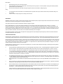
L-R Systems “WSB” series weigh scale blenders are designed to mix from 2 to 6 components according to
one of 99 recipes loaded in the memory. Materials are individually metered by vibratory feeders into the
batch weigh hopper until a recipe-based set point is reached. Weigh hoppers range in size from 25 to 250 lbs
capacity depending on the size of your blender. To permit increased accuracy, vibratory feeders have “slow
feed” set points adjustable from .3 lbs to 5.0 lbs before the final component weight set point is achieved.
After the batch is completed, the weigh hopper automatically dumps into our “First-in, First-out” mixing
barrel. This “dump time” is adjustable from 0 to 20 seconds. When a batch is dumped into the mixer a mixer
timer, which can be set between 0 and 60 seconds, starts timing. After the set mixing time this timer allows
your vacuum loading system to unload the mixed material from the mixing barrel or, as an option, opens the
slide gate to dump the mixing barrel into a collection box. (Contacts 103, 104)
The control panel features a Color touch screen with an easy to use Graphical User Interface (GUI), which
shows recipe entries, run status and alarm messages. The control panel also continuously totals the weight of
each component and stores this information for future retrieval. Information of totals and recipes can be
printed via RS232 serial communication port.
L-R Systems blenders have always been built rugged to last. Our standard for ample surge capacity,
thorough mixing, and outstanding performance makes L-R Blenders your best buy.
L-R blenders perform at or better than 0.02 lbs accuracy per component per batch.
2
INDEX
Page
1
2
3
4
5
6
7
8
9
10
11
12
13
14
14
15
16
17
18
19
20
21
22
23-30
31
Introduction
Index
Installation Instructions
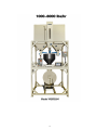
WSB 100
WSB 1000 - 8000
Controls – Main Screen
Controls – Recipe by Weight
Controls – Recipe by Percent
Controls – Recipe by Ratio
Controls – Run Mode
Controls – Manual Empty Bin
Controls – Alarms
Controls – Alarms
Controls – Diagnostics
Controls – Set-Up
Controls – Set-Up
Controls – Password
Maintenance
Printer Report
Communications Protocol
Bin Options
Electric motor information
Electric motor information
Vibratory Feeder Service Instructions
Warranty
3
INSTALLATION INSTRUCTIONS
-
Put the blender in place and anchor it down to the floor (if blender consists of several frames set the
bottom and assemble the machine).
-
Install vacuum chambers and connect vacuum and material lines.
-
If installing WSB100, attach vacuum chamber extensions to top plate prior to installing vacuum
chambers. Be sure to use mounting bolts provided which do not extend below top mounting plate.
Lower material bins are removable and must slide freely.
-
Attach the weigh chamber to the load cell.
-
Install rubber boot and the clamp. Make sure the boot is 1/2” above the safety bars in the mixer.
-
Connect the air tubes.
-
Make sure the ground wire is connected between weigh chamber and the frame.
-
Connect material lines to the vacuum take off tubes on the mixer barrel.
-
Bring 30A 480VAC service from MCC to the starter disconnect. Make sure the true GROUND is
connected to the blender’s frame. If no true ground available use ground rod to create one. Blender
consumes 2A 480VAC.
-
Bring the control wiring from vacuum loader control panel to the blender junction box (see blender
and vacuum loader wiring diagram):
• demand signal for bin #1 to terminal “A”
• demand signal for bin #2 to terminal “B”
• demand signal for bin #3 to terminal “C”
• demand signal for bin #4 to terminal “D”
• demand signal for bin #5 to terminal “E”
• demand signal for bin #6 to terminal “F”
• The HOT wire #3 to terminal 101.
-
If the vacuum control valves are installed on the blender connect the vacuum loader control panel
neutral #2 to terminal 200 and
• signal wire for valve on bin #1 to terminal 161
• signal wire for valve on bin #2 to terminal 162
• signal wire for valve on bin #3 to terminal 163
• signal wire for valve on bin #4 to terminal 164
• signal wire for valve on bin #5 to terminal 165
• signal wire for valve on bin #6 to terminal 166
4
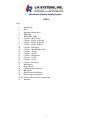
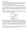
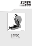
100 – 1000 lbs/hr
MODEL WSB 100
5
6
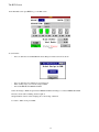
CONTROLS
The opening splash screen.
Fig. 1
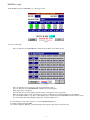
Main screen
Fig. 2
-
The various Status states are as follows: Stopped, Running, Initial, Dumping, Paused, Complete and ALARM
-
Dark blue areas: Data entries that accept user entry
-
Cyan areas: Calculated values
-
Gray areas: Running values
7
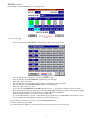
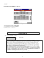
RECIPE by weight
From the Main screen press RECIPE to go to the recipe screen
Fig. 3
To create or edit recipe:
-
Press on dark blue area at RECIPE. The “Select Recipe To Edit” screen will be shown
Fig. 4
-
Press on dark blue area for recipe # to edit, Screen will return to Fig. 3
Press on dark blue area at DESCRIPTION, alphabetic key pad will appear
Enter recipe name or description.
Press the dark area above the chamber and enter name or description for each component.
Enter the desired weight for each component by pressing on dark blue areas with the number below the chamber.
If you would like blender to stop after so many batches, press on dark blue area at BATCHES and enter after how many.
If you would like the blender running continuously , leave this number at “0”.
If you would like to clear recipe and start it over use CLEAR PECIPE button.
To return to main screen press EXIT.
Note: When editing the “Running” recipe the blender will accept the edited recipe on the next cycle.
8
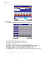
RECIPE by percent
From the Main screen press RECIPE to go to the recipe screen
Fig. 5
To create or edit recipe:
-
Press on dark blue area at RECIPE. The ‘Select Recipe To Edit” screen will be shown
-
Press on dark blue area for recipe # to edit, Screen will return to Fig. 5
Press on dark blue area at DESCRIPTION, alphabetic key pad will appear
Enter recipe name or description.
Press the dark area above the chamber and enter name or description for each component.
Press on dark blue area at RECIPE WEIGHT, numeric key pad will appear
Enter total recipe weight, press enter.
Choose between COLORED/NON COLORED material for bins 2 – 6, by pressing on dark blue area below the bin.
Enter the desired percentage for each component starting with the highest number by pressing on dark blue areas with the
number below the chamber. Notice that percentage of bin#2 will appear automatically.
Enter the desired percentage of color for non colored components.
If you would like blender to stop after so many batches, press on dark blue area at BATCHES and enter after how many.
If you would like the blender running continuously , leave this number at “0”.
Fig. 6
-
If you would like to clear recipe and start it over use CLEAR PECIPE button.
To return to main screen press EXIT.
Note: When editing the “Running” recipe the blender will accept the edited recipe on the next cycle.
9
RECIPE by Ratio
From the Main screen press RECIPE to go to the recipe screen
Fig. 7
To create or edit recipe:
- Press on dark blue area at RECIPE. The ‘Select Recipe To Edit” screen will be shown
Fig. 8
-
Bins with dark line above the number represent % based values
Press on dark blue area for recipe # to edit, Screen will return to Fig. 7
Press on dark blue area at DESCRIPTION, alphabetic key pad will appear
Enter recipe name or description.
Press the dark area above the chamber and enter name or description for each component.
Press on dark blue area below the chamber to enter COMPONENT WEIGHT, numeric key pad will appear
Press on dark brown area below the chamber to enter COMPONENT PERCENTAGE, numeric key pad will appear
If percentage is entered, weight is calculated by multiplying sum of all entered weights by the percentage.
Example: Bin 1 = 1 lb, Bin 2 = 3 lbs: User enters 25% for Bin 3, corresponding weight = 1 lb.
If you would like blender to stop after so many batches, press on dark blue area at BATCHES and enter after how many.
If you would like the blender running continuously, leave this number at “0”.
If you would like to clear recipe and start it over use CLEAR PECIPE button.
To return to main screen press EXIT.
Note: When editing the “Running” recipe the blender will accept the edited recipe on the next cycle.
10
The RUN Screen
From The Main screen press RUN to go to the Run screen
Fig. 7
To start blender:
-
Press on dark blue area at RECIPE. The Select Recipe To Run screen will be shown
Fig. 8
-
Press on dark blue area, numeric key pad will appear
Enter existing recipe (stored in the storage) number
Press CONTINUE ,then PRESS TO RUN
Status will change to RUN and green button PRESS TO RUN will change to red button PRESS TO STOP
The active feeder will be blinking and the weight on
Weigh Chamber window will be changing due to the feeding of material.
To return to Main screen press EXIT.
11
Manual EMPTY MATERIALS
From the Main screen press EMPTY MATERIALS to go to this screen
Fig. 9
You can empty each component by pressing dark blue area below the chamber.
The button OFF will change to ON and color of the chamber will be green.
Press one more time to stop.
To dump the weigh chamber, press on the button below the chamber
OFF will change to ON and color of the chamber will be green.
Press one more time to stop.
To dump the mixer barrel (if there is the slide gate on the bottom), press on the button below the MIXER TANK.
OFF will change to ON and color of the chamber will be green.
Press one more time to stop.
Press EXIT to return to the Main screen.
Manual TOTALS
From the Main screen press TOTALS to go to the TOTALS screen
Fig. 10
You can reset accumulated weight of each component by pressing RESET button.
Press EXIT to return to the Main screen.
12
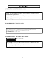
ALARMS
From the Main screen press ALARM to go to this screen
Fig. 11
You can clear alarms by pressing ALARM CLEAR.
To see the next page( if it exist) press CONTINUE.
Press EXIT to return to the Main screen.
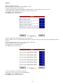
ALARMS
BIN x LOW LEVEL ALARM:
Bin #x Low LVL ALARM
Fill Bin to Continue
Top Line Flashes
At the start of each Weigh Chamber Fill Cycle, all Low Level sensors on the Bins used in the Recipe are checked. If
any Low Level sensors are ON, this Alarm Message will be shown, the Alarm Output contacts will close, and the
WBC will NOT start running. Pressing the STOP Key will take you out of Run and clear the Alarm message.
If a Low Level sensor comes ON during a Fill Cycle, the WBC will try to complete the current cycle. If there is
enough material to complete the cycle, the WBC will do so and then show the Alarm message & close the Alarm
Output contacts. The WBC will NOT start another Fill Cycle until the Low Level sensor goes OFF. Pressing the
STOP Key will take you out of Run and clear the Alarm message.
If there is NOT enough material to complete the Recipe from the Bin wilth the Low Level sensor ON (i.e. running
the Bin’s vibratory feeder for 15 seconds with no weight change), the WBC will stop the Fill Cycle, show the Alarm
message, and close the Alarm Output contacts. Since there is now a partial Recipe Batch in the weigh chamber, the
Bin with the low material must be filled before the process can continue.
If the ALARM ACK Key is pressed, only the Alarm Output contacts will open.
If the Bin Low Level sensor goes OFF, the Alarm Output contacts will open and the WBC will resume running.
13
ALARMS
MAXIMUM TARE WEIGHT EXCEEDED ALARM:
At the start of running each Recipe Batch, the WBC checks the current Tare Weight and compares it to the initial Run
Tare Weight. If the current Tare Weight is more than 25% of the Weigh Chamber size, greater than the initial Tare
Weight, this Alarm message will be displayed.
The WBC will stop running until the RUN or STOP Key is pressed.
If the RUN Key is pressed, the Alarm is ignored, the Alarm Output contacts open, and the WBC will continue
running.
If the STOP Key is pushed, the WBC will stop running.
This Alarm is NOT logged.
TOO MUCH BLENDER VIBRATION ALARM:
At the start of each Batch Fill Cycle, the WBC first checks the Load Cell weight reading for 3 seconds. If the reading
varies too much (probably due to too much Blender vibration), the WBC will show this Alarm message.
If the RUN Key is pressed, the WBC will try to start running the process again.
If the STOP Key is pressed, the WBC will stop.
This Alarm is NOT logged.
BAD FEEDER / JAMMED OR CLOSED CHUTE ALARM:
FEEDER #x PROBLEM
FIX Then Press RUN
Top Line Flashes
If a Recipe can NOT be completed from a Bin (i.e. running the Bin’s vibratory feeder for 15 seconds with no weight
change) and the Bin’s Low Level sensor is OFF, then show this Alarm message, close the Alarm Output contacts,
and stop the weigh chamber Fill Cycle.
If the ALARM ACK Key is pressed, open the Alarm Output contacts only.
If the RUN Key is pressed, open the Alarm Output contacts, turn ON the vibratory feeder and try running the
process again.
14
DIAGNOSTICS
From the Main screen press SYSTEM to go to Diagnostic screens.
Fig. 12
From this screen you can see the status of each input and output.
Press EXIT to return to the Main screen or
Press MORE to get to the next screen.
Fig. 13
Here you can turn ON and OFF each output and calibrate the analog input. (Look for calibration procedure).
Press EXIT to return to the Main screen or
Press MORE to get to the next screen.
SET-UP
From the Main screen press SETUP to go to Setup screens.
Fig. 14
15
SET-UP
Enter the existing load cell size.
Enter weigh chamber size calculated from CUBIC/FT X 35lb.
Set the mixer timer from 0 to 60 sec per cycle.
Set the weigh chamber dump time depending on maximum quantity of regrind in the recipes from 1 to 20 sec.
Set maximum stability depending on the vibration of the floor from 1 to 10.
Press EXIT to return to the Main screen or
Press MORE to get to the next screen.
Fig. 15
Change to YES if there is the holding tank below the mixer barrel.
Change to YES if you want to run the blender when regrind is going below the low level and ignore the regrind until level will not
be above.
Leave Control Mixer Motor NO if you want mixer running continuously.
Change to YES if you want to create recipes by %.
Press EXIT to return to the Main screen or
Press MORE to get to the next screen.
Fig. 16
Set slow speed points for each possible component.
Slower speed – more accurate feed, but longer filling time.
Press EXIT to return to the Main screen or
Press MORE to go to the first setup screen.
16
PASSWORD
Instructions for using the Password feature with the 5200 controller.
#1 is the PASSWORD screen. This screen has 3 items: Password Table, Lock System, Unlock System.
Password Table:
Passwords and access levels are set in this table. There are (8) eight available passwords, with the user
levels between 1 (being the highest security) and 3 (being the lowest security). Each password must be (8)
eight characters long to be valid. It is very important to change the user level of any unused password to the
lowest setting to avoid unauthorized personnel to have total access of the system.
To enter password:
Click on the (8) eight-digit numbers, enter new number, press ENT key
Repeat the process for entering the user level number.
Lock System:
This button will enable the password feature. Any screen requiring a password will prompt the user before
allowing access to the screen. After enabling passwords the following conditions will exist.
Level 3 access:
Screens available to a user with level 3
access is RUN, PASSWOD, and the first
screen of SYSTEM
Level 2 access:
Screens available to a user with level 2
are RUN, RECIPE, TOTALS, EMPTY
MATERIAL, ALARM, PASSWORD,
and the first and second screens of SYSTEM
Level 1 access:
Screens available to a user with level 1
access is RUN, RECIPE, TOTALS,
SETUP, EMPTY MATERIAL, ALARM
PASSWORD, and all screens of SYSTEM
On the third SYSTEM screen the options to Default to Factory Settings and Exit to System. In order to Exit
to System the default password set at the factory must be entered; the Exit to System button pressed to verify
the password. This password should not be available to any unauthorized personnel. The default value is
preset at 1973.
Unlock System:
This button is used to activate the different user levels. For example, you need to unlock all features
available to someone with level 2 access. First, press Unlock System button, enter password, press enter.
Now all level 2 screens are unlocked. Please note, that in order to lock the system to the highest security
level 1, the Lock System button must be pressed. If not, and someone with level 1 access inadvertently
forgot to press the Lock System button this would make all screens available to everyone. Please note, only
someone with level 1 access can enter the Password Table screen after Lock System is enabled.
17
MAINTENANCE
CALIBRATION
Calibration Function
1.
2.
3.
4.
5.
6.
7.
8.
The initial WC (initial weight on load cell) reading is an arbitrary value.
Press SET TARE and the WC displays 0 signifying the TARE has been selected.
Install calibration weight in weigh chamber.
WC will display the uncorrected weight.
Press blue “Cal lbs” and enter value of calibration weight.
Press CALIBRATE.
WC now displays the corrected weight.
% ADJUST shows the amount of correction applied (positive or negative).
NOTE: Each time the screen is opened, WC will contain an arbitrary value until TARE is pressed. Setting
TARE will then initiate the calibration process.
SETTING INSTRUCTIONS FOR LEVEL SENSORS
LEVEL SENSOR ADJUSTMENT
Level Sensor Adjustment Procedure
L-R Systems A125-L01 (KN0006 2-wire AC Normally Closed) High or Low level sensor
L-R Systems A125-L02 (KN0005 2-wire AC Normally Open) Low-Low level sensor
Note: There is only one N/O sensor in your blender eg: Mixer low level
With target product absent, press the push button until the green LED flashes (5 second Maximum) and then
release the button. After a short period, the green LED becomes constant.
The unit is now ready for operation.
18
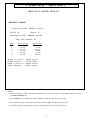
PRINTER
REPORT
Weigh Blender Controller (WBC)
SERIAL RS232 PRINTER PRINTOUT
PRINTOUT FORMAT:
Current Date & Time:
Station #: 05
05/04/96 - 13:21:34
Recipe #: 13
Initial Run Start Time:
05/04/96 - 08:55:05
Recipe Gaylord Batches: 05
Bin #
1
2
3
4
5
6
ALARM
ALARM
CLEAR
CLEAR
Recipe Weights
15.0 Lbs.
0.2 Lbs
1.0 Lbs.
0.5 Lbs.
0.3 Lbs.
2.0 Lbs.
-
Low Level #2
High Level
Low Level #2
High Level
-
05/04/96
05/04/96
05/04/96
05/04/96
Material Used
375.0 Lbs.
5.0 Lbs.
25.0 Lbs.
12.5 Lbs.
7.5 Lbs.
50.0 Lbs.
09:34:01
10:00:55
09:39:03
10:01:58
NOTES:
1- The above information will be sent out the serial RS232 port, if you are at the Top Level RUN Mode Menu and you press
the PRINT REPORT Key.
2- The serial RS232 port communication setup is 1200 baud, 8 data bits, No parity, and 1 stop bit.
3- If any Alarm Conditions occured, the last 30 will be save by the WBC and printed as shown above.
4- If the Printer produces a line feed after a carriage return, the above report will be double spaced.
19
COMMUNICATION PROTOCOL
Weigh Scale Blender Controller
REMOTE RS422 POLLING FOR INFORMATION
Information Request Data Packet:
(Control T)
(ID#) (Parameter B) (Parameter C)
A
B
C
A ID#
Valid Controller ID #s are 1 to 32
B Parameter B
1-Information on Recipe currently selected for running
+Current time and date
+Current run status
+Recipe #
+Initial run start time
+Bun #s used in recipe
+Total weight used by Bin #
+Recipe material weights
2-Information on saved Recipes. (in groups of 10 based on Parameter B)
+Recipe #
+# of gaylord batches (if used)
+Recipe material weights by Bin
3-Information on Set-Up Mode
C Parameter C (required only when Parameter B=2)
Defines recipe block: 0=recipes 1 to 10, 1=recipes 11 to 20, etc.
Notes:
1)
2)
3)
Only the controller with the polled ID# will respond to the information request.
Information will be returned in a comma separated value format.
The serial RS422 port communication set-up is 9600 baud, 8 data bits, no parity and 1 stop bit
20
SELF CLEANING BLENDER BIN OPTION
1.
2.
3.
4.
5.
6.
7.
8.
9.
10.
11.
12.
13.
14.
15.
Turn OFF station on vacuum loader.
Remove material through drain tube on bin and run BIN EMPTY MODE for that specified
bin.
Close slide gate on bin.
Hook up shop vac or small self contained vacuum hopper to 1-1/2" vacuum stub on bin and
start it.
Go to control panel and start the air pulsing.
Allow to cycle for several minutes and shut off.
Shut off shop vac.
Open slide gate.
Do visual inspection and wipe out any remaining residue.
OK to reload material.
When all bins are cleaned go to MANUAL DUMP MODE and dump material from weigh
hopper into mixer.
With mixer OFF open inspection doors and attach shop vac to vacuum take off.
Start shop vac and visually verify all material has been removed, wipe out remaining residue.
Secure all hoses and doors to mixer.
OK to start next blending batch.
NON SELF CLEANING BINS
1.
2.
3.
4.
5.
6.
Turn OFF station on vacuum loader.
Remove material through drain tube on bin until material falls below drain tube then close it.
Run BIN EMPTY MODE until all material is out of the bin into the weigh hopper.
Open bin access door and wipe out any remaining residue.
Go to MANUAL DUMP MODE and dump material from the weigh hopper into mixer.
Go to previous page lines 12 to 15.
REMOVABLE BINS
1.
2.
3.
4.
5.
6.
7.
8.
9.
10.
11.
Turn OFF Station on vacuum loader.
Unplug level sensors for bin to be cleaned and close the slide gate.
Tilt vibratory feeder down so that tube is parallel to floor.
Go to BIN EMPTY MODE on blender panel, select the desired bin and start. Run until all
material has been fed into the weigh hopper.
Loosen thumbscrews on the bin base and slide bin out. Dump material out and wipe clean.
Replace bin, tighten thumbscrews and connect level sensors.
Remove vacuum hose from mixer vacuum take off. Attach shop vac and turn ON.
Go to MANUAL DUMP MODE, dump material into the mixer and vacuum it out.
Loosen wing nuts on mixer and remove the back plate.
Empty mixer out and clean it.
Replace back plate and mixer. Tighten wing nuts. Blender is ready for next batch.
21
ELECTRIC MOTOR INFORMATION
SAFETY:
The use of electric motors and generators, like that of all other utilization of concentrated power, is potentially hazardous. The degree of hazard can be gratly reduced
by proper design, selection, installation and use, but hazards cannot be completely eliminated. The reduction of hazard is the joint responsibility of the user, the manufacturer of
the driven or driving equipment and the manufacturer of the motor or generator.
Motor products are designed and manufactured to comply to applicable safety standards and in particular to those issued by ANSI (American National Standards
Institute), NEMA (National Electrical Manufacturers Association), UL (Underwriters Laboratories, Inc) and CSA (Canadian Standards Association).
However, since even well-built apparatus can be installed or operated in a hazardous manner, it is important that safety considerations be observed by the user. With
respect to the load and environment, the user must properly select, install and use the apparatus - for guidance on all three aspects see safety standars publication No.
ANSI/NEAM MG-2.*
Standars Publication No. ANSI/NEMA MG-2. "safety Standard for Construction and Guide for Selection, Installation and Use of Electric Motors and Generators."
SELECTION:
Before proceeding with the installation, the user should review the application to confirm that the proper drive has been selected. This should be done after reading this notice and
all applicable safety standards. If in doubt, contact your L-R Reprentative in your area. Any selection or application suggestions made are only to assist the customer - and in all
cases, determination of fitness for purpose or use is solely the customer's responsibility.
Inspection: Examine for damage from shipment before connecting. Any claim (s) for shipping damage should be made to the freight carrier. do not attempt to turn the output shaft
of a gearmotor with an externally applied torque arm.
Mounting: Any screws, or similar devices, that penetrate the motor frame either for mounting the product or mounting something to the product should be limited in length so as
not to come in contact with or in close proximity to, intended features that conduct electricity. Spacings as high as.158" may be required based on voltages and circuitry involved.
Connection: Follow nameplate for voltage, frequency and phase of power supply. When connecting, make sure that your motor/gearmotor is securely and adequately grounded failure to ground properly may cause serious injury to personnel.
USE
Additional Safety Considerations
The chance of electric shocks, fires or explosions can be reduced by giving proper consideration to the use of grounding, thermal and over current protection, type of enclosure
and good maintenance procedures.
The following information supplements the foregoing safety considerations: This information is not purported to be all-inclusive and the aforementioned references should be
consulted.
1.
2.
3.
4.
5.
6.
7.
8.
9.
10.
11.
Do not insert objects into the ventilation openings of products.
Sparking of starting switches in AC motors so equipped, and of brushes in commutator type motors, can be expected during normal operation. In addition, open type
enclosures may eject flame in the event of an insulation failure. Therefore, avoid, protect from, or prevent the presence of flammable or combustible materials in the
area of motors/gearmotors.
Totally enclosed products are not explosion proof or dust ignition proof nor do we offer such products for hazardous locations (flammable/explosive gas, vapor, dust).
When dealing with hazardous locations, an approved explosion proof or dust ignition proof product is the recommended approach. Exceptions are allowed by the
National Electrical Cod: The NBC and NEMA safety standard should be studied thoroughly before exercising this option.
Open, ventilated motors are suitable for clean, dry locations where cooling air is not restricted. Enclosed motors/gearmotors are suitable for dirty, damp locations. For
outdoor use, wash downs, etc., enclosed motors must be protected by a cover while still allowing adequate air flow.
Moisture will increase the electrical shock hazard of electrical insulation. Therefore, consideration should be given th the avoidance of (or protection from) liquids in
the area of motors. Use of totally enclosed motors/gearmotors will reduce the hazard if all openings are sealed.
Products equipped with thermal protectors are labeled "THERMALLY PROTECTED." If severe over-loading, jamming, or other abnormal operating conditions occur,
such heat sensitive protectors operate to open the electric power supply circuit. Motors/gearmotors with "automatic" thermal protectors MUST NOT be used where
automatic restarting of the drive unit could be hazardous in that clothing or parts of the human body could be in electrical or physical contact with a machine that starts
unexpectedly when the thermal protector cools down. MANUAL RESET protectors or suitable electric supply disconnect devices/procedures should be used where
such hazards could be created.
Some oil-type capacitors are identified by means of a Warning Label and, in addition, are stamped "NON-PCB." The user has to provide at least .57 in. (14.5 mm)
clearance beyond the terminal blades for case expansion to allow an internal safety switch to permanently open and electrically disconnect the capacitor. The internal
pressure sensitive switch is designed to prevent the expulsion of the flammable dielectric medium if excessive temperatures are generated by electrical operation. Do
not discard such capacitors into open fire as excessive external heat could cause them to explode.
Motors/gearmotors which employ capacitors, can develop more than nameplate voltage across the capacitor and/or capacitor winding (depending on design). Also,
overdrive voltages may be many times greater than a stepper motor's continuous voltage rating. Suitable precautions should be taken when applying such motors.
Abnormal conditions such as cut-out switch failure, or a partial winding failure can very occasionally cause some AC motors/gearmotors to start in a direction reverse
from normal. Also, use capacitance or resistance value other than that recommended for Hy-Sync motors may result in unpredictable reverse operation.
Susceptablility to unplanned reversing under such conditions is greatest when the motor's actual load is light relative to it's rated load. One-way clutches or similar
devices are advisable if unexpected reverse rotation is unsafe in the application.
Do not rely upon self-locking gears or permanent magnet, stepper, Hy-Sync or energized motors to hold a load in place if movement could result in personal injury.
Mechanical looking devices should be used in such applications.
For motors driven by electronic controls, do not use a function of the control for safety interlock purposes. An independent switch or relay should be used. On stepper
motors, the device should be between the control and the motor.
22
Before Starting
1.
2.
3.
Before attempting to start, check all connections and fuses.
Proper consideration should be given to rotating members: Before starting, be sure keys, pulleys, etc. are securely fastened. Proper guards should be provided to
prevent hazards to personnel while rotating.
Other mechanical considerations include proper mounting and alignment of products and safe loads on shafting and gearing.
Staring
1.
2.
The motor/gearmotor should be test-started in an unloaded state (because of possible reaction torque, the drive should be securely mounted when starting - even
when unloaded).
If the drive unit does not start promptly and run smoothly, disconnect at once.
MAINTENANCE
IMPORTANT - Before servicing or working on equipment, disconnect power source (this applies especially to equipment using automatic restart devices instead of manual restart
devices and when examining or replacing brushes on brush type motors/gearmotors).
Clean regularly to prevent dirt and dust from interfering with ventilation or clogging moving parts.
Brush Type Motors/Gearmotors - The wear rate of brushes is dependent upon many parameters (armature speed, amperage duty cycle, humidity, etc.). For optimum
performance brush type motors and gearmotors need periodic user-maintenance. The maintenance interval is best determined by the user. Inspect brushes regularly for wear
(replace in same axial position). Replace brushes when their length is less than 1/4 in. (7 mm). Periodically remove carbon dust from commutator and inside the motor - this can
be accomplished by occasionally wiping them with a clean, dry, non-linting cloth. Do not use lubricants or solvents on the commutator. If necessary, use No. 0000 or finer sand
paper only to dress the commutator. Do not use solvents on a non-metallic end shield if the product is so equipped.
Products Employing Capacitors - Before servicing motors/gearmotors employing capacitors, always discharge the capacitor by placing a conductor across its terminals before
touching the terminals with any part of your body.
LUBRICATION INSTRUCTIONS
Motor Ball Bearings (not gearhead bearings) - are grease lubricated and do not normally require re-lubircation or replacement for a period of approximately five years if run under
normal operating conditions (defined above). More adverse conditions generally require more frequent servicing. Do not over-grease ball bearings as shortened life can result.
Motor Sleeve Bearings (not gearhead sleeve bearings) - sleeve bearing motors are identified by the presence of oil holes or oilers on the motor endshields. Motor sleeve bearings
should be relubricated every six months or 1000 operational hours (whichever comes first) when used under normal operating conditions as defined above. For motors under (4)
inches in diameter, relubricate with 5-6 drops of SAE No. 10 non-detergent oil. For larger diameter motors, relubricate with 5-6 drops of SAE #20 non-detergent oil. More sever
conditions will require more frequent servicing. Do not over lubricate.
Gearhead Lubrication - Gearmotors consists of a motor portion and a gearhead portion. The previous sections dealt with motor bearings - the following text concerns gearhead
(gear and gear shaft bearing) lubrication.
A.
Oil lubricated Gearmotors (identified by the presence on an oil level sight gauge or plug marked "Oil Level"). Oil lubricated gearheads are shipped with a red plastic
plug in their vent holes. When operating under normal operating conditions, check oil level every 4 to 5 months or 600 operating hours - which ever occurs first.
1.
Type "1D" Gearheads: These gearmotors are identified by the "1D" appearing after a hyphen in the TYPE box on the nameplate. For example. For example: N__1_D- (where the identifying designators are illustrated and a "_" indicates the location of any other number or letter). Refill "-1D" gearheads tot he indicated oil level
with a good quality rust and oxidation inhibited oil conforming to AGMA #5 (SAE#50 non-detergent) with a viscosity range of 918-1122 SUS at 100o F, viscosity index
of 90 minimum, and pour point of 0o F maximum. Do not over fill.
2.
Oil Lubricated Gearmotors other than Type "1D": These gearmotors can be identified as follows: examine the nomenclature in the "TYPE" box on the nameplate: if
any of the combinations of numbers and letters defined below appear after a hyphen, the gearmotor is oil lubricated. (The identifying designators are illustrated and a
"_" symbol indicates the position of any other number or letter).
Refill these gearmotors to oil level indicated on the respective product with a good quality worm gear oil conforming to AGMA #5EP compounded (SAE#90). Do not
over-fill.
3.
NOTE: For test and run-in of gearmotors that are applied to equipment for resale, remove red plastic vent hole plug from oil fill vent hole. If gearmotor may be tipped
during shipment, replace plastic plug and include instructions to remove the plug before operating the gearmotor.
B.
Grease Lubricated Gearmotors: Grease lubricated gearmotors can be identified as follows: examine the nomenclature in the "TYPE" box on the nameplate; If any of
the combinations of numbers and letters defined below appear after a hyphen, the gearmotor is grease lubricated. (The locations of the identifying designators are
illustrated and a "_" symbol indicates the position of any other number or letter).
The above gearmotors are supplied with sufficient grease to last for the "design life" of the gearmotors. Some right-angle gearheads mayhave oilers on their output
shaft hubs. The oilers should be relubricated every three months with 5-6 drops of SAE#20 non-detergent oil.
23
Service Instructions
Syntron
Light-Capacity
Electromagnetic
Vibrating Feeders
Models:
F-T01-A and DF-T01-A
Contents
Page
Introduction..............................................24
Theory of Operation.................................25
Long Term Storage..................................26
Installation ...............................................26
Operation.................................................27
Maintenance ............................................27
Trouble Shooting .....................................28
Spring Replacement ................................29
Air Gap ....................................................29
Checking Feeder Current ........................30
Stroke Gauge ..........................................30
Parts List .................................................31
L-R Systems, Inc. reserves the right to make changes at any time, without notice and without any liability
or other obligation on its part, in material, equipment, specifications and model. L-R Systems also
reserves the right to discontinue the manufacture and sale of models, and the parts and components
thereof.
Safety Instructions: Product safety labels must remain highly visible on the equipment. Should
safety labels require replacement contact L-R Systems, Material Handling Solutions for an
additional supply free of charge.
The instructions and data herein are vital to the proper installation and operation of this equipment. In
order to avoid delays due to faulty installation or operation, please see that these instructions are read by
the persons who will install, operate and maintain this equipment.
Supporting information, such as drawings, may be attached to this manual. The information contained
therein take precedence over corresponding information printed in this manual.
INTRODUCTION
The Syntron F/DF-T01-A Feeder assembly is an electromagnetic unit, consisting of a dynamically
balanced, two-mass vibrating system. This system consists of a trough and trough connecting bracket
coupled to an electromagnetic drive by means of leaf springs.
NOTE: When supplied without a trough assembly, the drive unit can be used with chutes, tracks, etc.
(supplied by the customer).
The drive (a coil and core assembly) is located within the base housing and is connected directly to the
rear of drive unit housing. An armature assembly, also included as part of the drive unit, is located opposite
the core and coil and is connected directly to the trough connecting bracket. The springs are clamped at
the bottom to the drive unit housing, at the top to the trough connecting bracket. The trough, trough
connecting bracket and armature become an assembly, joined to the drive unit through the spring
assemblies.
24
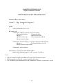
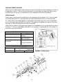
THEORY OF OPERATION
Model F/DF-T01-A Feeder operation produces a vibrating stroke on the surface of the feeder trough. The
stroke is obtained by the electromagnet pulling the trough sharply down and back and then allowing it to
spring up and forward. Repeated at high speeds (3600 v.p.m. at 60 cycle power supply), this action
produces a definite vibrating movement on the trough surface.
The F/DF-T01-A Feeder requires the use of separate control which contains a rectifier (SCR), used to
convert alternating current into rectified current. Service Instructions are included with the control.
Figure 1 illustrates a typical a-c sine wave and a typical r-c sine wave (the type of pulsating current which
is required to operate the feeder). The coil is energized only by the portion of the sine wave shown as a
solid line of the r-c sine wave. The broken line represents the portion of the sine wave which is blocked by
the rectifier. The blocked portion does not reach the feeder coil and during this time the feeder coil is deenergized.
When the coil is energized, the core becomes magnetized and attracts the armature assembly. This pulls
the armature, trough mounting bracket and trough down and back towards the core. This pull is against
the mid-point of the leaf spring stack, flexing the springs.
FIGURE 1–THE RECTIFIED SINE WAVE
Each power half cycle is followed by a half cycle of blocked current flow during this half cycle, power is not
available to the coil and the coil becomes de-energized. With the coil de-energized, the magnetic pull
between the core and armature is released and the leaf spring system is permitted to spring back to (and
slightly through) its normal position. This pulls the trough, bracket and armature assembly up and forward.
On the next power half cycle, the trough, trough mounting bracket and armature are again pulled down
and back. On the next no power half cycle, the trough, trough mounting bracket and armature assembly
are again pulled up and forward. Thus, during operation, the trough is continually vibrating along a straight
line path.
The unit is mechanically adjusted to limit the travel of the armature so it does not strike against the face of
the core. The space between the armature and core is called the “air gap”. The size of the air gap is critical
to good feeder operation. Instructions concerning the air gap are on page 6.
25
LONG TERM STORAGE
When received, the equipment should be carefully unpacked. Give the equipment a thorough visual
inspection to reveal any damage that may occurred during shipment. If damage is found, contact L-R
Systems, Material Handling Solutions and the shipping carrier at once.
If the feeder is placed in storage, prior to installation, store the feeder in the shipping carton.
CAUTION: Do not support the weight of the unit by the trough assembly. This will distort and damage the springs.
When storing the controller, plug all openings in the control box to prevent dirt, rodents and insects from
entering. L-R Systems advises placing a corrosion preventive inside control box. Cover the controller and
place it in an area protected from extreme heat. Do not drop controller. The force of the impact may
damage the components.
INSTALLATION
CAUTION: Do not lift the unit by the trough.
The feeder has been factory tuned for your specific application. Handling by the trough could cause
damage to the feeder.
When received the feeder and controller should be carefully unpacked. All packing bands, paper, etc.,
must be removed. Check the controller components for protective shipping blocks, tape etc.
Inspect all the equipment received and report any damage, which may have occurred during shipment. If
damage is found, notify L-R Systems, Material Handling Solutions and the shipping carrier at once.
When installing the feeder, consideration must be given to the area of support. Model F/DF-T01-A feeders
can weigh over 33 pounds (15 kg) and a support must be selected that will safely carry the full weight of
the unit under loaded operating conditions.
CAUTION: The feeder must not come in contact with any rigid object or adjacent surface that could
hamper its vibrating action.
A ½” (12.7 mm) clearance must be maintained. Any connections (such as dust seals) between the trough
and adjacent objects must be flexible, preferably cloth or rubber.
WARNING: Be certain the equipment is properly grounded.
26
OPERATION
CAUTION: Unauthorized modification of the feeder or use of unauthorized replacement parts may damage the
feeder.
L-R Systems will not assume responsibility for feeder performance as a result of any unauthorized
alterations to the equipment. Consult L-R Systems, Material Handling Solutions before modifying your
feeder.
With the feeder and controller properly installed and all wiring completed, the equipment is ready for
operation.
WARNING: While in operation the controller must be kept closed and secured.
Before starting the equipment, check all external bolts on the feeder assembly for tightness. Then, rotate
the control knob on the controller to a low counterclockwise position. Turn the switch to its “on” position
and the feeder will begin operating at a low rate of feed. Check the method of feeder support, making sure
it is substantial and the feeder is not touching any rigid objects or an adjacent structure.
CAUTION: When operating normally, the feeder should perform with a smooth even stroke. If a
loud “striking” noise occurs, immediately turn off feeder.
Striking is the result of the faces of the core and armature making contact. Striking can result in serious
damage to the unit! Refer to the Air Gap section of these instructions for corrective action.
With the feeder operating satisfactorily, load the trough with the material to be conveyed and adjust the
control knob to the desired output. Clockwise rotation will increase the feed rate; counterclockwise will
decrease the feed rate. The material will flow along the trough surface in a smooth controlled rate of feed
toward the discharge.
MAINTENANCE
WARNING: Before performing any maintenance work, the electrical power supply must be
disconnected at the safety disconnect switch and locked out.
Some materials, due to their nature, adhere to the trough surfaces. These deposits increase dead weight
to the feeder trough, and if permitted to build up excessively, will alter the natural frequency (tuning) of the
feeder. Material build-up on the trough should be removed as a daily practice. Look for material build-up at
the rear of the feeder trough, particularly around and under hopper openings.
A clean, dry compressed air supply is recommended for general cleaning of these units. Water is not
recommended.
CAUTION: Never oil the spring assembly. This destroys the clamping effect of the spring
pads against one another.
In the event repairs are necessary, take immediate action to avoid possible injury to personnel and
damage to the feeder parts from faulty operation. When ordering replacement parts, include all information
given on the nameplate.
27
CAUTION: Any signs of excessive heat or burned components are an indication of trouble. At first
notice of an overheating condition, immediately investigate and correct the cause.
Feeder coils, under normal operating conditions, run warm but never too hot to touch.
TROUBLE SHOOTING
PROBLEM
Feeder operates too slow
CAUSE
Line voltage below designated
rating
CORRECTION
Increase line voltage as designated
on the nameplate
Unit in contact with rigid object or
surface
Maintain proper clearances
Spring action may be hampered
Clean spring assemblies
Defective leaf springs
Replace *
Worn or cracked trough
Line voltage above designated
rating. High voltage will cause a
“striking” condition.
Replace *
Reduce line voltage as designated
on the nameplate
Unit hums, will not vibrate
Defective SCR within controller
(refer to controller instructions)
Replace *
Unit fails to operate
No power to controller
Check for broken or grounded lines
Defective switch or fuse
Replace *
Defective SCR within controller
(refer to controller instructions)
Replace *
Feeder coil burned out or
grounded
Replace *
Short circuit in wiring
Repair
Open winding on rheostat
Replace *
Feeder operates too fast
* Replace parts only with those supplied or recommended by L-R Systems
28
SPRING REPLACEMENT
Replacement springs must be of the same size and thickness as those removed. L-R Systems
recommends replacing all springs rather than just one.
Before replacing springs, disconnect the feeder from the power supply. Work on one spring assembly at a
time (first the rear spring stack). Make a note of the location and arrangement of each spring, spacer and
clamp. Remove the bolts which secure the leaf springs to the base, then the bolts which hold the springs to
the trough mounting bracket.
Install the new spring assembly in reverse order of that removed. Replace cap screws and torque as
specified on page 6.
AIR GAP
The air gap is the spacing that exists between the faces of the armature and core assemblies. Proper
adjustment of this space is extremely important for good feeder operation.
If the air gap is adjusted so the armature and core are too close, the faces of these items will make contact
during feeder operation. This is called “striking”.
CAUTION: If a loud striking noise occurs, immediately turn the unit off. When operating normally, the
feeder should perform with a smooth even stroke.
If the air gap is adjusted so the armature and core are too far apart, the feeder current may increase to a
dangerous level. A high current condition will result in coil burn-out, failure of control components or a
reduced material feed rate.
The air gap is properly set at the factory, re-adjustment should rarely be required. However, if high voltage
is applied to the feeder or if the air gap has been altered due to improper handling an adjustment may be
in order.
While following this procedure refer to the illustration on page 7.
Loosen hex nut (K) and insert a screwdriver into the slot on the end of the core (M). Turning the core
clockwise will narrow the air gap; counterclockwise will widen the air gap. The proper air gap is reached
when the air gap is as narrow as possible without a striking condition.
The designated current rating must not be exceeded.
When the proper air gap has been obtained, lock the core in place by tightening the hex nut (K).
F/DF-T01-A units operate with the trough stroke between .045” to .050” (1.1 to 1.3 mm). This is checked at
the stroke gauge on the trough assembly.
The air gap adjustment is a very delicate procedure and may require some time to properly obtain the
desired setting. The correct air gap spacing will be obtained when the armature and core faces are as
close as possible without “striking” when maximum current is applied to the feeder magnet.
29
CHECKING FEEDER CURRENT
When using an analog clamp on meter to read the current of the feeder, the meter reading must always be
multiplied by a value of 1.7 due to the wave characteristics of the feeder when operating. When using a
true RMS meter, the current is as indicated. All current readings must be taken at the control.
STROKE GAUGE
Feeder stroke is the distance the trough travels in one complete cycle of vibration. This is measured from
the forward upward limit of the vibrating stroke to the downward backward limit of the vibrating stroke.
This stroke can be measured by applying a stroke gauge to the feeder trough. Be certain the graduated
lines on the gauge are parallel with the line of drive. The gauge can be applied at any point on the side of
the trough, as close to the centerline of the drive as possible.
Under vibration, a black “V” will appear on the gauge. The amplitude of the unit can be read at the apex of
this black “V”. The lines should appear solid black; if fuzzy and gray, the graduated lines of the gauge are
not parallel to the line of the drive.
OPERATING INSTRUCTIONS
Maximum trough weight
7.0 Lbs. (3.2 kg)
Trough Stroke Range
.045” to .050” (1.1 to
1.3 mm)
Minimum Natural Frequency 3330 VPM (50 CY)
4000 VPM (60 CY)
Maximum Current Rating
.9 amps 115V/50-60
(nameplate)
CY
.45 amps 230V/50-60
CY
TORQUE SPECIFICATIONS
Item No.
Torque Value (In/Lbs)
Dry
*Lubricated
C,D
350 (39.6 Nm)
260 (29 Nm)
*Plated fasteners are considered Lubricated.
30
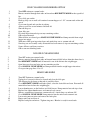
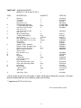
PARTS LIST – VIBRATING FEEDER
MODELS: F-T01-A and DF-T01-A
ITEM
DESCRIPTION
QUANTITY
PART NO.
A
Armature
Armature
Dust Seal
Lockwasher (1/4”)
Trough Mounting Bracket
Trough Mounting Bracket
Cap Screw, Hex Hd., NiPl
(3/8”-16 x 1 1/2”)
Cap Screw, Hex Hd., NiPl
(3/8”-16 x 1 1/4”)
Spring Clamping Bar}
Spring Clamping Bar}
Spring Spacer
Leaf Spring (.050” Tk.) (1.3 mm)
Leaf Spring (.070” Tk.) (1.8 mm)
Spring Seat
Spring Seat
Rubber Cushion, Standard
Rubber Cushion, Sandwich Type
Rubber Cushion, Stud Type
Mach, Screw, Rd. Hd., Br.
(#10-32 x 3/8”)
Hex Jam Nut (1”-14)
Core
Backplate
Backplate
Mach. Screw, Rd. Hd.
(1/4”-20 x 5/8”)
Coil & Cable Assembly (115V)
Coil & Cable Assembly (230V)
Coil Washer
Base Casting
Base Casting
*Nameplate
1
1
1
1
{1
only}
4
A-81697-A
A-81697-B
A-59185
H0112858
D-226957-001
D-226957-002
H0310622
4
H0310322
{4
only}
As Req’d.
{As
Req’d.}
4
4
{4
only}
1
A-59177
B-97584
A-63773
A-96252-A
A-96252-B
A-59176
A-98650
0207X033
0207X037
0207X040
H0203102
1
1
{1
only}
4
H0107005
A-81698-B
A86342
A-86342-A
H0205102
{1
only}
2
{1
only}
1
B-83423-A
B-83423-B
A-81849
C-81354-A1
C-81354-A2
A-62245
*Label (Disc. Elec.)
2
A-125694
B
C
D
E
F
G
H
J
K
M
N
P
Q
R
S
* Do not remove or paint over safety labels. If labels should require replacement, contact L-R Systems,
Material Handling Solutions for an additional supply free of charge.
Applicable to DF-T01-A Units Only.
Service Manual SM0751-083002
31
NOTICE REGARDING
DAMAGE & RETURNS
This merchandise left our plant in first class condition and may Not be
returned for any reason without proper authorization from L-R SYSTEMS.
If anything in this crate or package is found damaged in any manner, you
must call at once for an inspection by the Transportation Company. Save
the crate or container and wrappings to show the inspector. The inspector
will give you a form, filled out, stating the results of this inspection. You may
contact us for a duplicate invoice and/or copy of the bill of lading, which we
will furnish promptly. With these papers and the inspector’s report, you must
file a claim for the cost of repairs or replacement with the transportation
company, L-R SYSTEMS cannot do this. The inspection and claim must be
originated at your end of this shipment.
If there should be damage concealed of such nature that it could not be
detected until the goods were unpacked, call the transportation company at
once and have them inspect the damages. They will fill out a Concealed
bad Order Report stating the condition of the goods when examined.
On parcel post shipments, file claim with the Post Office.
shipments, file claim with UPS.
On UPS
We are not responsible for any damage incurred while merchandise is in
transit. The transportation company will settle promptly all claims as they
are insured and their rates cover this cost.
Any merchandise returned to L-R SYSTEMS will be refused unless
accompanied with a return goods authorization form. Contact the L-R
SYSTEMS sales department or your sales representative to obtain this
authorization.
Any merchandise returned to L-R SYSTEMS, with the required return
authorization, must be FREIGHT PREPAID
L-R SYSTEMS
PNEUMATIC SYSTEMS, INC.
470 SOUTH HAMMES AVENUE
JOLIET, IL 60436
PHONE 815-730-9912
FAX 815-730-9655