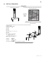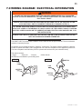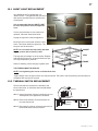
1
1 INSTALLER: LEAVE THIS MANUAL WITH THE APPLIANCE. CONSUMER: RETAIN THIS MANUAL FOR FUTURE REFERENCE. INSTALLATION AND OPERATING INSTRUCTIONS CERTIFIED UNDER CANADIAN AND AMERICAN NATIONAL STANDARDS: CSA 2.33, ANSI Z21.88 FOR VENTED GAS FIREPLACE HEATERS. CDV70NT-S NATURAL GAS CDV70PT-S PROPANE CERTIFIED FOR CANADA AND UNITED STATES USING ANSI/CSA METHODS. SAFETY INFORMATION ! WARNING If the information in these instructions are not followed exactly, a fire or explosion may result causing property damage, personal injury or loss of life. - Do not store or use gasoline or other flammable vapors and liquids in the vicinity of this or any other appliance. - WHAT TO DO IF YOU SMELL GAS: • Do not try to light any appliance. • Do not touch any electrical switch; do not use any phone in your building. • Immediately call your gas supplier from a neighbour’s phone. Follow the gas supplier’s instructions. • If you cannot reach your gas supplier, call the fire department. - Installation and service must be performed by a qualified installer, service agency or the supplier. Wolf Steel Ltd., 24 Napoleon Rd., Barrie, ON, L4M 4Y8 Canada / 103 Miller Drive, Crittenden, Kentucky, USA, 41030 Phone (705)721-1212 • Fax (705)722-6031 • www.continentalfireplaces.com • [email protected] $10.00 1.9 W415-0570 / C / 11.10.09 2 TABLE OF CONTENTS 1.0 2.0 3.0 INSTALLATION OVERVIEW INTRODUCTION 3 4 2.1 2.2 2.3 2.4 2.5 5 5 6 7 7 VENTING 3.1 3.2 3.3 3.3.1 3.4 3.5 3.6 3.7 3.8 3.9 4.0 5.0 6.0 7.0 8.0 9.0 10.0 11.0 12.0 13.0 14.0 15.0 DIMENSIONS GENERAL INSTRUCTIONS GENERAL INFORMATION RATING PLATE INFORMATION CARE OF GLASS VENTING LENGTHS AND COMPONENTS TYPICAL VENT INSTALLATION SPECIAL VENT INSTALLATION PERISCOPE TERMINATION VENT TERMINAL CLEARANCES VENTING APPLICATION FLOW CHART DEFINITIONS ELBOW VENT LENGTH VALUES TOP EXIT HORIZONTAL TERMINATION VERTICAL TERMINATION 8 8 9 10 10 11 12 12 12 13 15 INSTALLATION 17 4.1 4.1.1 4.1.2 4.2 4.2.1 4.2.2 4.2.3 4.3 4.3.1 4.3.2 4.4 4.5 4.6 4.7 17 18 18 19 19 20 21 21 21 22 22 23 23 24 WALL AND CEILING PROTECTION HORIZONTAL SHIELDING VERTICAL SHIELDING USING FLEXIBLE VENT COMPONENTS HORIZONTAL AIR TERMINAL INSTALLATION VERTICAL AIR TERMINAL INSTALLATION APPLIANCE VENT CONNECTION USING RIGID VENT COMPONENTS HORIZONTAL AIR TERMINAL INSTALLATION VERTICAL AIR TERMINAL INSTALLATION RESTRICTING VERTICAL VENTS GAS INSTALLATION OPTIONAL WALL SWITCH / THERMOSTAT MOBILE HOME INSTALLATION FRAMING 24 5.1 5.2 5.3 5.4 26 27 28 28 MINIMUM CLEARANCE TO COMBUSTIBLES PROTRUDING FINISH MINIMUM CLEARANCE TO COMBUSTIBLE ENCLOSURES MINIMUM MANTEL CLEARANCES FINISHING 29 6.1 6.2 6.3 6.4 6.5 6.6 6.7 6.8 6.9 6.10 29 30 30 30 30 30 32 32 32 32 DOOR INSTALLATION DOOR CLOSING AND OPENING LOG SHIPPING BRACKET DECORATIVE PANELS CHARCOAL STRIPS LOG PLACEMENT CHARCOAL EMBERS GLOWING EMBERS LOUVRE INSTALLATION LOGO PLACEMENT WIRING DIAGRAM / ELECTRICAL INFORMATION OPERATION ADJUSTMENTS 33 34 35 9.1 9.2 9.3 35 35 36 PILOT BURNER ADJUSTMENT VENTURI ADJUSTMENT FLAME CHARACTERISTICS MAINTENANCE 36 10.1 10.2 10.3 37 37 38 NIGHT LIGHT REPLACEMENT THERMAL SWITCH REPLACEMENT BLOWER REPLACEMENT REPLACEMENTS TROUBLE SHOOTING WARRANTY SERVICE HISTORY NOTES W415-0570 / C / 11.10.09 39 43 45 46 47 3 1.0 INSTALLATION OVERVIEW Venting, see “VENTING” section. Louvre, see “LOUVRE INSTALLATION” section. See “FINISHING” section for Log shipping bracket, Decorative panels, Charcoal Strip, Log placement, Charcoal and glowing embers. Logo, see “LOGO PLACEMENT” section. Door, see “DOOR INSTALLATION” section. W415-0570 / C / 11.10.09 4 2.0 INTRODUCTION ! • • • • • • • • • • • • • • • • • • • • • • • • • • WARNING THIS APPLIANCE IS HOT WHEN OPERATED AND CAN CAUSE SEVERE BURNS IF CONTACTED. Do not operate appliance before reading and understanding operating instructions. Failure to operate appliance according to operating instructions could cause fire or injury. Risk of fire or asphyxiation do not operate appliance with fixed glass removed. Do not connect 110 volts to the control valve. Risk of burns. The appliance should be turned off and cooled before servicing. Do not install damaged, incomplete or substitute components. Risk of cuts and abrasions. Wear protective gloves and safety glasses during installation. Sheet metal edges may be sharp. Do not burn wood or other materials in this appliance. Young children should be carefully supervised when they are in the same room as the appliance. Toddlers, young children and others may be susceptible to accidental contact burns. A physical barrier is recommended if there are at risk individuals in the house. To restrict access to an appliance or stove, install an adjustable safety gate to keep toddlers, young children and other at risk individuals out of the room and away from hot surfaces. Clothing or other flammable material should not be placed on or near the appliance. Due to high temperatures, the appliance should be located out of traffic and away from furniture and draperies. Ensure you have incorporated adequate safety measure to protect infants/toddlers from touching hot surfaces. Even after the appliance is out, the glass and/or screen will remain hot for an extended period of time. Check with your local hearth specialty dealer for safety screens and hearth guards to protect children from hot surfaces. These screens and guards must be fastened to the floor. Any safety screen or guard removed for servicing must be replaced prior to operating the appliance. It is imperative that the control compartments, burners and circulating blower and its passageway in the appliance and venting system are kept clean. The appliance and its venting system should be inspected before use and at least annually by a qualified service person. More frequent cleaning may be required due to excessive lint from carpeting, bedding material, etc. The appliance area must be kept clear and free from combustible materials, gasoline and other flammable vapors and liquids. Under no circumstances should this appliance be modified. This appliance must not be connected to a chimney flue pipe serving a separate solid fuel burning appliance. Do not use this appliance if any part has been under water. Immediately call a qualified service technician to inspect the appliance and to replace any part of the control system and any gas control which has been under water. Do not operate the appliance with the glass door removed, cracked or broken. Replacement of the glass should be done by a licensed or qualified service person. Do not strike or slam shut the appliance glass door. This appliance uses and requires a fast acting thermocouple. Replace only with a fast acting thermocouple supplied by Wolf Steel Ltd. Pressure relief doors must be kept closed while the appliance is operating to prevent exhaust fumes containing carbon monoxide, from entering into the home. Temperatures of the exhaust escaping through these openings can also cause the surrounding combustible materials to overheat and catch fire. Only doors / optional fronts certified with the unit are to be installed on the appliance. Keep the packaging material out of reach of children and dispose of the material in a safe manner. As with all plastic bags, these are not toys and should be kept away from children and infants. As with any combustion appliance, we recommend having your appliance regularly inspected and serviced as well as having a Carbon Monoxide Detector installed in the same area to defend you and your family against Carbon Monoxide. 3.1 W415-0570 / C / 11.10.09 5 2.1 DIMENSIONS ! WARNING THE DOOR FOR THIS APPLIANCE IS SOLD SEPARATELY. THE DOOR MUST BE INSTALLED AND CLOSED BEFORE OPERATION BEGINS. SEE “DOOR INSTALLATION” SECTION FOR FURTHER DETAILS. 41 1/2" 24" 4" DIA. 7" DIA. 36" GAS INLET 7" 16" 18" 11" 4" RATING PLATE LOCATION 2.2 ELECTRICAL INLET LEFT SIDE 18 5/8" 37 1/4" GENERAL INSTRUCTIONS ! WARNING ALWAYS LIGHT THE PILOT WHETHER FOR THE FIRST TIME OR IF THE GAS SUPPLY HAS RAN OUT, WITH THE GLASS DOOR OPENED OR REMOVED. PROVIDE ADEQUATE CLEARANCE FOR SERVICING AND OPERATING THE APPLIANCE. PROVIDE ADEQUATE VENTILATION. NEVER OBSTRUCT THE FRONT OPENING OF THE APPLIANCE. OBJECTS PLACED IN FRONT OF THE APPLIANCE MUST BE KEPT A MINIMUM OF 48” FROM THE FRONT FACE OF THE UNIT. FIRE RISK. EXPLOSION HAZARD. HIGH PRESSURE WILL DAMAGE VALVE. DISCONNECT GAS SUPPLY PIPING BEFORE PRESSURE TESTING GAS LINE AT TEST PRESSURES ABOVE 1/2 PSIG. CLOSE THE MANUAL SHUT-OFF VALVE BEFORE PRESSURE TESTING GAS LINE AT TEST PRESSURES EQUAL TO OR LESS THAN 1/2 PSIG. USE ONLY WOLF STEEL APPROVED OPTIONAL ACCESSORIES AND REPLACEMENT PARTS WITH THIS APPLIANCE. USING NON-LISTED ACCESSORIES (BLOWERS, DOORS, LOUVRES, TRIMS, GAS COMPONENTS, VENTING COMPONENTS, ETC.) COULD RESULT IN A SAFETY HAZARD AND WILL VOID THE WARRANTY AND CERTIFICATION. THIS GAS APPLIANCE SHOULD BE INSTALLED AND SERVICED BY A QUALIFIED INSTALLER to conform with local codes. Installation practices vary from region to region and it is important to know the specifics that apply to your area, for example in Massachusetts State: • This product must be installed by a licensed plumber or gas fitter when installed within the commonwealth of Massachusetts. • The appliance damper must be removed or welded in the open position prior to installation of a appliance insert or gas log. • The appliance off valve must be a “T” handle gas cock. • The flexible connector must not be longer than 36 inches. • A Carbon Monoxide detector is required in all rooms containing gas fired appliances. • The appliance is not approved for installation in a bedroom or bathroom unless the unit is a direct vent sealed combustion product. W415-0570 / C / 11.10.09 6 The installation must conform with local codes or, in absence of local codes, the National Gas and Propane Installation Code CSA B149.1 in Canada, or the National Fuel Gas Code, ANSI Z223.1 / NFPA 54 in the United States. Suitable for mobile home installation if installed in accordance with the current standard CAN/CSA Z240MH Series, for gas equipped mobile homes, in Canada or ANSI Z223.1 and NFPA 54 in the United States. www.nficertified.org We suggest that our gas hearth products be installed and serviced by professionals who are certified in the U.S. by the National Fireplace Institute® (NFI) as NFI Gas Specialists As long as the required clearance to combustibles is maintained, the most desirable and beneficial location for an appliance is in the center of a building, thereby allowing the most efficient use of the heat created. The location of windows, doors and the traffic flow in the room where the appliance is to be located should be considered. If possible, you should choose a location where the vent will pass through the house without cutting a floor or roof joist. If the appliance is installed directly on carpeting, vinyl tile or other combustible material other than wood flooring, the appliance shall be installed on a metal or wood panel extending the full width and depth. If the optional fan or blower is installed, the junction box must be electrically connected and grounded in accordance with local codes, use the current CSA C22.1 Canadian Electrical Code in Canada or the ANSI/ NFPA 70 National Electrical code in the United States. 4.1 2.3 GENERAL INFORMATION FOR YOUR SATISFACTION, THIS APPLIANCE HAS BEEN TEST-FIRED TO ASSURE ITS OPERATION AND QUALITY! CDV70 NG LP Altitude (FT) 0-4,500 0-4500 Max. Input (BTU/HR) 35,000 33,000 Max. Output (BTU/HR) 28,350 26,400 Efficiency (w/the fan on) 81% 80% A.F.U.E. 64% 65% Min. Inlet Gas Supply Pressure 4.5" Water Column 11" Water Column Max. Inlet Gas Supply Pressure 7" Water Column 13" Water Column 3.5" Water Column 10" Water Column Manifold Pressure (Under Flow Conditions) When the appliance is installed at elevations above 4,500ft, and in the absence of specific recommendations from the local authority having jurisdiction, the certified high altitude input rating shall be reduced at the rate of 4% for each additional 1,000ft. No external electricity (110 volts or 24 volts) is required for the gas system operation. Expansion / contraction noises during heating up and cooling down cycles are normal and are to be expected. Change in flame appearance from “HI” to “LO” is more evident in natural gas than in propane. 8” is the minimum bend radius allowed for the 7” diameter flexible air liner. W415-0570 / C / 11.10.09 7 2.4 RATING PLATE INFORMATION 9 MODEL 9 REFERENCE # W/N 15525 MODEL CERTIFIED FOR CANADA AND US ET CERTIFIEE POUR GD70 F INSTALLER: It is your responsibility to check off the appropriate box on the rating plate according to the model, venting and gas type of the appliance. For rating plate location, see “DIMENSIONS” section. 2.5 CARE OF GLASS DO NOT CLEAN GLASS WHEN HOT! DO NOT USE ABRASIVE CLEANERS TO CLEAN GLASS. ! WARNING HOT GLASS WILL CAUSE BURNS. Buff lightly with a clean dry soft cloth. Clean both sides of the glass after the first 10 hours of operation with a recommended fireplace glass cleaner. Thereafter clean as required. If the glass is not kept clean permanent discoloration and / or blemishes may result. DO NOT TOUCH GLASS UNTIL COOLED. NEVER ALLOW CHILDREN TO TOUCH GLASS. 5.1 W415-0570 / C / 11.10.09 8 3.0 VENTING ! WARNING RISK OF FIRE, MAINTAIN SPECIFIED AIR SPACE CLEARANCES TO VENT PIPE AND APPLIANCE. IF VENTING IS INCLUDED WITH SPACERS THE VENT SYSTEM MUST BE SUPPORTED EVERY 3 FEET FOR BOTH VERTICAL AND HORIZONTAL RUNS. USE SUPPORTS OR EQUIVALENT NON-COMBUSTIBLE STRAPPING TO MAINTAIN THE REQUIRED CLEARANCE FROM COMBUSTIBLES. USE WOLF STEEL LTD. SUPPORT RING ASSEMBLY W010-0370 OR EQUIVALENT NON-COMBUSTIBLE STRAPPING TO MAINTAIN THE MINIMUM CLEARANCE TO COMBUSTIBLES FOR BOTH VERTICAL AND HORIZONTAL RUNS. SPACERS ARE ATTACHED TO THE INNER PIPE AT PREDETERMINED INTERVALS TO MAINTAIN AN EVEN AIR GAP TO THE OUTER PIPE. THIS GAP IS REQUIRED FOR SAFE OPERATION. A SPACER IS REQUIRED AT THE START, MIDDLE AND END OF EACH ELBOW TO ENSURE THIS GAP IS MAINTAINED. THESE SPACERS MUST NOT BE REMOVED. THIS APPLIANCE USES A 4” EXHAUST / 7” AIR INTAKE VENT PIPE SYSTEM. Refer to the section applicable to your installation. For safe and proper operation of the appliance follow the venting instruction exactly. Deviation from the minimum vertical vent length can create difficulty in burner start-up and/or carboning. Under extreme vent configurations, allow several minutes (5-15) for the flame to stabilize after ignition. Vent lengths that pass through unheated spaces (attics, garages, crawl spaces) should be insulated with the insulation wrapped in a protective sleeve to minimize condensation. Provide a means for visually checking the vent connection to the appliance after the appliance is installed. Use a firestop, vent pipe shield or attic insulation shield when penetrating interior walls, floor or ceiling. NOTE: If for any reason the vent air intake system is disassembled; reinstall per the instructions provided for the initial installation. 7.1 3.1 VENTING LENGTHS AND COMPONENTS Use only Wolf Steel, Simpson Dura-Vent, Selkirk Direct Temp, American Metal Amerivent or Metal-Fab venting components. Minimum and maximum vent lengths, for both horizontal and vertical installations, and air terminal locations for either system are set out in this manual and must be adhered to. For Simpson Dura-Vent, Selkirk Direct Temp, American Metal Amerivent and Metal-Fab follow the installation procedure provided with the venting components. A starter adaptor must be used with the following vent systems and may be purchased from the corresponding supplier: PART 4”/7” SUPPLIER WEBSITE Duravent W175-0053 Wolf Steel www.duravent.com Amerivent 4DSC-N2 American Metal www.americanmetalproducts.com Direct Temp 4DT-AAN Selkirk www.selkirkcorp.com SuperSeal 4DNA Metal-Fab www.mtlfab.com For Simpson Dura-Vent, Selkirk Direct Temp, American Metal Amerivent and Metal-Fab follow the installation procedure found on the website for your venting supplier. For vent systems that provide seals on the inner exhaust flue, only the outer air intake joints must be sealed using a red high temperature silicone (RTV). This same sealant may be used on both the inner exhaust and outer intake vent pipe joints of all other approved vent systems except for the exhaust vent pipe connection to the appliance flue collar which must be sealed using the black high temperature sealant Mill Pac. High temperature sealant must be ordered separately. When using Wolf Steel venting components, use only approved Wolf Steel rigid / flexible components with the following termination kits: wall terminal kit GD222, GD222R, or 1/12 to 7/12 pitch roof terminal kit GD110, 8/12 to 12/12 roof terminal kit GD111, flat roof terminal kit GD112 or periscope kit GD201 (for wall penetration below grade). With flexible venting, in conjunction with the various terminations, use either the 5 foot vent kit GD220 or the 10 foot vent kit GD330. W415-0570 / C / 11.10.09 9 For optimum flame appearance and appliance performance, keep the vent length and number of elbows to a minimum. The air terminal must remain unobstructed at all times. Examine the air terminal at least once a year to verify that it is unobstructed and undamaged. Rigid and flexible venting systems must not be combined. Different venting manufacturer components must not be combined. These vent kits allow for either horizontal or vertical venting of the appliance. The maximum allowable horizontal run is 20 feet. The maximum allowable vertical vent length is 40 feet. The maximum number of vent connections is two horizontally or three vertically (excluding the appliance and the air terminal connections) when using flexible venting. 3.2 8.1 TYPICAL VENT INSTALLATION 16” MINIMUM ! 24” MAXIMUM WARNING THE FIRST TWO FEET OF OUTER 7” DIAMETER VENT PIPE FROM THE APPLIANCE MUST BE WRAPPED IN THE 1” THICK INSULATION SLEEVE (SUPPLIED). 3 FEET MINIMUM 40 FEET MAXIMUM 10” MIN 36” 46” MINIMUM PLUS RISE* 36” 45.6 * See “VENTING” section Horizontal runs may have a 0” rise per foot in all cases using Simpon Dura-vent or Napoleon rigid or flexible venting components when venting as illustrated. For optimum performance, it is recommended that all horizontal runs have a 1” rise per foot. When terminating vertically, the vertical rise is a minimum 36” and a maximum 40 ft from the center of the appliance flue outlet. W415-0570 / C / 11.10.09 10 3.3 SPECIAL VENT INSTALLATION 3.3.1 PERISCOPE TERMINATION Use the periscope kit to locate the air termination above grade. The periscope must be installed so that when final grading is completed, the bottom air slot is located a minimum 12” above grade. The maximum allowable vent length is 10’. 12” MIN TO GRADE 30” MIN 36” 9.3 W415-0570 / C / 11.10.09 11 3.4 VENT TERMINAL CLEARANCES INSTALLATIONS A CANADA U.S.A. 12” 12” Clearance above grade, veranda porch, deck or balcony. B 12” 9” Clearance to windows or doors that open. C 12” * 12” * Clearance to permanently closed windows. D 18” ** 18” ** Vertical clearance to ventilated soffits located above the terminal within a horizontal distance of 2’ from the centerline of the terminal. E 12” ** 12” ** Clearance to unventilated soffit. F 0” 0” 0” *** 0” *** Clearance to an inside non-combustible corner wall or protruding non-combustible obstructions (chimney, etc.). 2” *** 2” *** Clearance to an inside combustible corner wall or protruding combustible obstructions (vent chase, etc.). H 3’ 3’ **** Clearance to each side of the centerline extended above the meter / regulator assembly to a maximum vertical distance of 15’. I 3’ 3’ **** Clearance to a service regulator vent outlet. J 12” 9” K 6’ 3’ † G L 7’ ‡ 7’ **** M 12” †† 12” **** Clearance to an outside corner wall. Clearance to a non-mechanical air supply inlet to the building or a combustion air inlet to any other appliance. Clearance to a mechanical air supply inlet. Clearance above a paved sidewalk or paved driveway located on public property. Clearance under a veranda, porch, deck or balcony. N 16” 16” Clearance above the roof. O 2’ †* 2’ †* Clearance from an adjacent wall including neighbouring buildings. * Recommended to prevent condensation on windows and thermal breakage ** it is recommended to use a heat shield and to maximize the distance to vinyl clad soffits. *** The periscope requires a minimum 18 inches clearance from an inside corner. **** This is a recommended distance. For additional requirements check local codes. † 3 feet above if within 10 feet horizontally. ‡ A vent shall not terminate directly above a sidewalk or paved driveway that is located between two single family dwellings and serves both dwellings. †† Permitted only if the veranda, porch, or deck is fully open on a minimum of two sides beneath the floor. †* Recommended to prevent recirculation of exhaust products. For additional requirements check local codes. NOTE: Clearances are in accordance with local installation codes and the requirements of the gas supplier. 12.1 W415-0570 / C / 11.10.09 12 3.5 VENTING APPLICATION FLOW CHART Horizontal Termination Vertical Termination Vertical rise is equal to or greater than the horizontal run Vertical rise is less than horizontal run Vertical rise is equal to or greater than the horizontal run Vertical rise is less than horizontal run Horizontal run + vertical rise to maximum of 40 feet Horizontal run + vertical rise to maximum of 24.75 feet Horizontal run + vertical rise to maximum of 40 feet Horizontal run + vertical rise to maximum of 40 feet 4.2 times the vertical rise equal to or greater than the horizontal run 3 times the vertical rise equal to or greater than the horizontal run 13.1 3.6 DEFINITIONS For the following symbols used in the venting calculations and examples are: > - greater than > - equal to or greater than < - less than < - equal to or less than HT - total of both horizontal vent lengths (Hr) and offsets (Ho) in feet HR - combined horizontal vent lengths in feet HO - offset factor: .03 (total degrees of offset - 90°*) in feet VT - combined vertical vent lengths in feet 14.1 3.7 ELBOW VENT LENGTH VALUES 1° 15° 30° 45° 90°* FEET 0.03 0.45 0.9 1.35 2.7 INCHES 0.5 6.0 11.0 16.0 32.0 * The first 90° offset has a zero value and is shown in the formula as - 90° 15.1 W415-0570 / C / 11.10.09 13 3.8 TOP EXIT HORIZONTAL TERMINATION (HT) < (VT) Simple venting configuration (only one 90° elbow) See graph to determine the required vertical rise VT for the required horizontal run HT. 39 40 30 REQUIRED VERTICAL RISE IN FEET VT 20 10 0 2.5 5 7.5 10 12.5 15 17.5 20 HORIZONTAL VENT RUN PLUS OFFSET IN FEET HT The shaded area within the lines represents acceptable values for HT and VT For vent configurations requiring more than one 90° elbow, the following formulas apply: Formula 1: HT < VT Formula 2: HT + VT < 40 feet Example 1: V1 = 3 FT V2 = 8 FT VT = V1 + V2= 3 FT + 8 FT = 11 FT H1 = 2.5 FT H2 = 2 FT HR = H1 + H2 = 2.5 + 2 = 4.5 FT HO = .03 (three 90° elbows - 90°) = .03 (270° - 90°) = 5.4 FT HT = HR + HO = 4.5 + 5.4 = 9.9 FT HT + VT = 9.9 + 11 = 20.9 FT HT < VT 9.9 < 11 Formula 2: HT + VT < 40 FT 20.9 < 40 Since both formulas are met, this vent configuration is acceptable. Formula 1: 90° H2 V2 90° H1 90° V1 16.1 W415-0570 / C / 11.10.09 14 (HT) > (VT) Simple venting configuration (only one 90° elbow) See graph to determine the required vertical rise VT for the required horizontal run HT. 147” 150 100 REQUIRED VERTICAL RISE IN INCHES VT 57” 50 19 1/2” 0 5 15 10 2’ 12.5’ 20 19.5’ HORIZONTAL VENT RUN PLUS OFFSET IN FEET HT The shaded area within the lines represents acceptable values for HT and VT For vent configurations requiring more than one 90° elbow, the following formulas apply: Formula 1: HT < 4.2 VT Formula 2: HT + VT < 24.75 feet H1 90° Example 2: V1 = VT = 6 FT H1 = 3 FT H2 = 5 FT HR = H1 + H2 = 3 + 5 = 8 FT HO = .03 (two 90° elbows - 90°) = .03 (180° - 90°) = 2.7 FT HT = HR + HO = 8 + 2.7 = 10.7 FT HT + VT = 10.7 + 6 = 16.7 FT HT < 4.2 VT 4.2 VT = 4.2 x 6 = 25.2 FT 10.7 < 25.2 Formula 2: HT + VT < 24.75 FT 16.7 < 24.75 Since both formulas are met, this vent configuration is acceptable. H2 90° V1 Formula 1: Example 3: V1 = 4 FT V2 = 1.5 FT VT = V1 + V2 = 4 + 1.5 = 5.5 FT H1 = 2 FT H2 = 1 FT H3 = 1 FT H4 = 1.5 FT HR = H1 + H2 + H3 + H4 = 2 + 1 + 1 + 1.5 = 5.5 FT HO = .03 (four 90° elbows - 90°) = .03 (360° - 90°) = 8.1 FT HT = HR + HO = 5.5 + 8.1 = 13.6 FT HT + VT = 13.6 + 5.5 = 19.1 FT HT < 4.2 VT 4.2 VT = 4.2 x 5.5 = 23.1 FT 13.6 < 23.1 Formula 2: HT + VT < 24.75 FT 19.1 < 24.75 Since both formulas are met, this vent configuration is acceptable. 90° V1 H1 90° V2 H2 H 3 90° Formula 1: W415-0570 / C / 11.10.09 90° 16.1_2 H4 15 3.9 VERTICAL TERMINATION (HT) < (VT) Simple venting configurations. See graph to determine the required vertical rise VT for the required horizontal run HT. 40 30 REQUIRED VERTICAL RISE IN FEET VT 20 10 3 0 5 10 15 20 HORIZONTAL VENT RUN PLUS OFFSET IN FEET HT The shaded area within the lines represents acceptable values for HT and VT For vent configurations requiring one or more 90° elbows the following formulas apply: Formula 1: HT < VT Formula 2: HT + VT < 40 feet Example 6: V1 = 5 FT V2 = 6 FT V3 = 10 FT VT = V1 + V2 + V3 = 5 + 6 + 10 = 21 FT H1 = 8 FT H2 = 2.5 FT HR = H1 + H2 = 8 + 2.5 = 10.5 FT HO = .03 (four 90° elbows - 90°) = .03 (360° - 90°) = 8.1 FT HT = HR + HO = 10.5 + 8.1 = 18.6 FT HT + VT = 18.6 + 21 = 39.6 FT 90° V3 90° H2 V2 H1 V1 90° 90° Formula 1: HT < 3.5 VT 18.6 < 21 Formula 2: HT + VT < 40 FT 39.6 < 40 Since both formulas are met, this vent configuration is acceptable. 18.1 W415-0570 / C / 11.10.09 16 (HT) > (VT) Simple venting configurations. See graph to determine the required vertical rise VT for the required horizontal run HT. 19 REQUIRED VERTICAL RISE IN FEET VT 20 10 3 0 5 10 15 25 20 30 HORIZONTAL VENT RUN PLUS OFFSET IN FEET HT The shaded area within the lines represents acceptable values for HT and VT For vent configurations requiring more than two 90° elbows the following formulas apply: Formula 1: HT < 3VT Formula 2: HT + VT < 40 feet Example 2: V1 = 2 FT V2 = 1 FT V3 = 1.5 FT VT = V1 + V2 + V3 = 2 + 1 + 1.5 = 4.5 FT H1 = 6 FT H2 = 2 FT HR = H1 + H2 = 6 + 2 = 8 FT HO = .03 (four 90° elbows - 90°) = .03 (360° - 90°) = 8.1 FT HT = HR + HO = 8 + 8.1 = 16.1 FT HT + VT = 16.1 + 4.5 = 20.6 FT 90° 90° V1 H2 H1 V2 V3 90° 90° Formula 1: HT < 3VT 3VT = 3 x 4.5 = 13.5 FT 16.1 > 13.5 Since this formula is not met, this vent configuration is unacceptable. Formula 2: HT + VT < 40 feet 20.6 < 40 Since only formula 2 is met, this vent configuration is unacceptable and a new fireplace location or vent configuration will need to be established to satisfy both formulas. 18.1_2 W415-0570 / C / 11.10.09 17 4.0 INSTALLATION ! WARNING FOLLOW THE VENTING INSTRUCTIONS EXACTLY. ALL INNER EXHAUST AND OUTER INTAKE VENT PIPE JOINTS MAY BE SEALED USING EITHER RED RTV HIGH TEMP SILICONE SEALANT W573-0002 (NOT SUPPLIED) OR BLACK HIGH TEMP MILL PAC W573-0007 (NOT SUPPLIED) WITH THE EXCEPTION OF THE APPLIANCE EXHAUST FLUE COLLAR WHICH MUST BE SEALED USING MILL PAC. IF USING PIPE CLAMPS TO CONNECT VENT COMPONENTS, 3 SCREWS MUST ALSO BE USED TO ENSURE THE CONNECTION CANNOT SLIP OFF. DO NOT CLAMP THE FLEXIBLE VENT PIPE. RISK OF FIRE, EXPLOSION OR ASPHYXIATION. IMPROPER SUPPORT OF THE ENTIRE VENTING SYSTEM MAY ALLOW VENT TO SAG AND SEPARATE. USE VENT RUN SUPPORTS AND CONNECT VENT SECTIONS PER INSTALLATION INSTRUCTIONS. RISK OF FIRE, DO NOT ALLOW LOOSE MATERIALS OR INSULATION TO TOUCH THE VENT PIPE. REMOVE INSULATION TO ALLOW FOR THE INSTALLATION OF THE ATTIC SHIELD AND TO MAINTAIN CLEARANCES TO COMBUSTIBLES. 68.2 4.1 WALL AND CEILING PROTECTION ! WARNING DO NOT FILL THE SPACE BETWEEN THE VENT PIPE AND ENCLOSURE WITH ANY TYPE OF MATERIAL. DO NOT PACK INSULATION OR COMBUSTIBLES BETWEEN CEILING FIRESTOPS. ALWAYS MAINTAIN SPECIFIED CLEARANCES AROUND VENTING AND FIRESTOP SYSTEMS. INSTALL WALL SHIELDS AND FIRESTOPS AS SPECIFIED. FAILURE TO KEEP INSULATION OR OTHER MATERIALS AWAY FROM VENT PIPE MAY CAUSE FIRE. 70.1 For clearances to combustible materials from the vent pipe, see “FRAMING” section. For optimum performance it is recommended that all horizontal runs have a minimum 1” rise per foot when using flexible venting. W415-0570 / C / 11.10.09 18 4.1.1 HORIZONTAL SHIELDING ! WARNING TERMINALS MUST NOT BE RECESSED INTO A WALL OR SIDING MORE THAN THE DEPTH OF THE RETURN FLANGE OF THE MOUNTING PLATE. This application occurs when venting through an exterior wall. Having determined the correct height for the air terminal location, cut and frame a hole in the exterior wall as illustrated to accommodate the firestop assembly. CAULKING Dry fit the firestop assembly before proceeding to ensure the brackets on the rear surface fit to the inside surface of the horizontal framing. FIRESTOP SPACER The length of the vent shield may be cut shorter for combustible walls that are less than 8 1/2” thick but the vent shield must extend the full depth of the combustible wall. 11 1/2” 11 1/2” DETERMINE THE CORRECT HEIGHT FINISHING MATERIAL A. Apply a bead of caulking (not supplied) around the corner edge of the inside surface of the firestop assembly, fit the firestop assembly to the hole and secure using the 4 screws (supplied in your manual baggie). B. Once the vent pipe is installed in its final position, apply high temperature sealant W573-0007 (not supplied) between the pipe and the firestop. 20.6 NOTE: The 11 1/2” framing dimension may be reduced to a 9 1/2” opening if the vent length, from the appliance to the framed hole, is 24” or greater. If not, it is recommended to use a terminal extension plate, W500-0103, when mounting the air terminal. 4.1.2 VERTICAL SHIELDING This application occurs when venting through a roof. Installation kits for various roof pitches are available from your authorized dealer / distributor. See accessories to order specific kits required. A. Determine the air terminal location, cut and frame a square opening as illustrated in the ceiling and the roof to provide the minimum 1“ clearance between the vent pipe and any combustible material. Try to center the vent pipe location midway between two joists to prevent having to cut them. Use a plumb bob to line up the center of the openings. A vent pipe shield will prevent any materials such as insulation, from filling up the 1” air space around the pipe. Nail headers between the joist for extra support. B. Apply a bead of caulking (not supplied) to the framework or to the Wolf Steel vent pipe shield plate or equivalent (in the case of a finished ceiling), and secure over the opening in the ceiling. A firestop must be placed on the bottom of each framed opening in a roof or ceiling that the venting system passes through. Apply a bead of caulking all around and place a firestop spacer over the vent shield to restrict cold air from being drawn into the room or around the fireplace. Ensure that both spacer and shield maintain the required clearance to combustibles. Once the vent pipe is installed in its final position, apply sealant between the pipe and the firestop assembly. 9 1/2" FIRESTOP UNDERSIDE OF JOIST VENT PIPE SHIELD C. In the attic, slide the vent pipe collar down to cover up the open end of the shield and tighten. This will prevent any materials, such as insulation, from filling up the 1” air space around the pipe. 21.1 W415-0570 / C / 11.10.09 9 1/2" CAULKING VENT PIPE COLLAR VENT PIPE SHIELD 4.2 19 USING FLEXIBLE VENT COMPONENTS ! WARNING DO NOT ALLOW THE INNER FLEX PIPE TO BUNCH UP ON HORIZONTAL OR VERTICAL RUNS AND ELBOWS. KEEP IT PULLED TIGHT. SPACERS ARE ATTACHED TO THE INNER FLEX PIPE AT PREDETERMINED INTERVALS TO MAINTAIN AN EVEN AIR GAP TO THE OUTER FLEX PIPE. THIS GAP IS REQUIRED FOR SAFE OPERATION. A SPACER IS REQUIRED AT THE START, MIDDLE AND END OF EACH ELBOW TO ENSURE THIS GAP IS MAINTAINED. THESE SPACERS MUST NOT BE REMOVED. ELBOW SPACERS For safe and proper operation of the appliance, follow the venting instructions exactly. All inner flex pipe and outer flex pipe joints may be sealed using high temperature sealant W573-0002 (not supplied) or the high temperature sealant W573-0007 Mill Pac (not supplied). However, the high temperature sealant W573-0007 Mill Pac (not supplied) must be used on the joint connecting the inner flex pipe and the exhaust flue collar. Use only approved flexible vent pipe kits marked: “Wolf Steel Approved Venting” as identified by the stamp only on the outer flex pipe. 22.1 4.2.1 HORIZONTAL AIR TERMINAL INSTALLATION A. B. C. D. Stretch the inner flex pipe to the required length taking into account the additional length needed for the finished wall surface. Slip the vent pipe a minimum of 2” over the inner sleeve of the air terminal and secure with 3 #8 screws. Apply a heavy bead of the high temperature sealant W573-0007 Mill Pac (not supplied). #10x2" SCREWS CAULKING INNER FLEX PIPE 2" OVERLAP Using the outer flex pipe, slide over the outer combustion air sleeve of the air terminal and secure with 3 #8 screws. Seal using high temperature sealant W573-0002 (not supplied). Insert the vent pipes through the firestop maintaining the required clearance to combustibles. Holding the air terminal (lettering in an upright, readable position), secure to the exterior wall and make weather tight by sealing with caulking (not supplied). OUTER FLEX PIPE HI-TEMP SEALANT HI-TEMP SEALANT #8 X 1/2” SELF DRILLING SCREWS & WASHERS INNER COUPLER OUTER COUPLER OUTER FLEX PIPE OUTER If more vent pipe needs to be used to reach INNER the fireplace, couple them together as FLEX PIPE FLEX PIPE illustrated. The vent system must be supported approximately every 3 feet for both vertical and horizontal runs. Use noncombustible strapping to maintain the minimum 1” clearance to combustibles. The air terminal mounting plate may be recessed into the exterior wall or siding no greater than the depth of its return flange. 23.3 W415-0570 / C / 11.10.09 20 4.2.2 VERTICAL AIR TERMINAL INSTALLATION ! WARNING MAINTAIN A MINIMUM 2” SPACE BETWEEN THE AIR INLET BASE AND THE STORM COLLAR. A. Fasten the roof support to the roof using the screws provided. The roof support is optional. In this case the venting is to be adequately supported using either an alternate method suitable to the authority having jurisdiction or the optional roof support. B. Stretch the inner flex pipe to the required length. Slip the inner flex pipe a minimum of 2” over the inner pipe of the air terminal connector and secure with 3 #8 screws. Seal using a heavy bead of high temperature sealant W573-0007 (not supplied). C. Repeat using the outer flex pipe, using a heavy bead of high temperature sealant W573-0002 (not supplied). D. E. F. ROOF SUPPORT INNER PIPE Thread the air terminal connector / vent pipe assembly down through the roof. The air terminal must be positioned vertically and plumb. Attach the air terminal connector to the roof support, ensuring that the AIR top of the air terminal is 16” above the highest point that it penetrates TERMINAL the roof. CONNECTOR HIGH Remove nails from the shingles, above and to the sides of the air TEMPERATURE terminal connector. Place the flashing over the air terminal connector SEALANT leaving a min. 3/4” of the air terminal connector showing above INNER FLEX PIPE the top of the flashing. Slide the flashing underneath the sides and upper edge of the shingles. Ensure that the air terminal connector OUTER FLEX PIPE is properly centred within the flashing, giving a 3/4” margin all around. Fasten to the roof. Do not nail through the lower portion of the flashing. Make weather-tight by sealing with caulking. Where possible, cover the sides and top edges of the flashing with roofing material. Aligning the seams of the terminal and air terminal connector, place the terminal over the air terminal connector making sure the vent pipe goes into the hole in the terminal. Secure with the three screws provided. AIR INLET BASE 2” CAULKING STORM COLLAR WEATHER SEALANT G. Apply a heavy bead of weatherproof caulking 2” above the flashing. Install the storm collar around the air terminal and slide down to the caulking. Tighten to ensure that a weather-tight seal between the air terminal and the collar is achieved. H. If more vent pipe needs to be used to reach the appliance see “HORIZONTAL AIR TERMINAL INSTALLATION” section. FLASHING 24.1 W415-0570 / C / 11.10.09 21 4.2.3 APPLIANCE VENT CONNECTION A. Install the inner flex pipe to the appliance. Secure with 3 screws and flat washers. Seal the joint and screw holes using the high temperature sealant W573-0007 (not supplied). B. Install the outer flex pipe to the appliance. Attach and seal the joints using the high temperature sealant W573-0002 (not supplied). #8 X 1/2” SELF DRILLING SCREWS 2” OVERLAP HIGH TEMP SEALANT 28.1 4.3 USING RIGID VENT COMPONENTS The vent system must be supported approximately every 3 feet for both vertical and horizontal runs. Use Wolf Steel Ltd. support ring assembly or equivalent noncombustible strapping to maintain the minimum clearance to combustibles for both vertical and horizontal runs. All inner exhaust and outer intake vent pipe joints may be sealed using either red high temperature silicone sealant W573-0002 (not supplied) or black high temperature sealant W573-0007 Mill Pac (not supplied) with the exception of the appliance exhaust flue collar which must be sealed using Mill Pac. 25.1 4.3.1 HORIZONTAL AIR TERMINAL INSTALLATION A. Move the fireplace into position. Measure the vent length required between terminal and fireplace taking into account the additional length needed for the finished wall surface and any 1¼” overlaps between venting components. #10 x 2½" SCREWS CAULKING OUTER INNER PIPE PIPE 2" OVERLAP B. Apply high temperature sealant W573-0007 (not supplied) to the outer edge of the inner collar of the fireplace. Attach the first inner rigid pipe component and secure using 3 self tapping screws. Repeat using the outer rigid pipe. C. Insert the vent pipes through the firestop maintaining the required clearance to combustibles. Holding the air terminal (lettering in an upright, readable position), secure to the exterior wall and make weather tight by sealing with caulking (not supplied). HI-TEMP SEALANT The air terminal mounting plate may be recessed into the exterior wall or siding no greater than the depth of its return flange. 26.2 W415-0570 / C / 11.10.09 22 4.3.2 VERTICAL AIR TERMINAL INSTALLATION A. B. C. D. E. F. G. H. I. J. Move the appliance into position. INNER PIPE Fasten the roof support to the roof using the screws provided. The roof support is optional. In this case the venting is to be adequately supported using either an alternate method suitable to the authority AIR having jurisdiction or the optional roof support. TERMINAL Apply high temperature sealant W573-0007 (not supplied) to the CONNECTOR outer edge of the inner sleeve of the air terminal. Slip the inner coupler a minimum of 2” over the sleeve and secure using 3 screws. HIGH Apply high temperature sealant W573-0002 (not supplied) to the TEMPERATURE outer edge of the of the outside sleeve of the air terminal connector. SEALANT Slip the outer coupler over the sleeve and secure as before. Trim the INNER RIGID outer coupler even with the inner coupler end. PIPE Thread the air terminal connector / vent pipe assembly down through the roof support and attach, ensuring that a minimum 16” of air OUTER terminal connector will penetrate the roof when fastened. If the attic RIGID PIPE space is tight, we recommend threading the Wolf Steel vent pipe collar or equivalent loosely onto the air terminal connector / vent pipe assembly as it is passed through the attic. The air terminal connector must be located vertically and plumb. Remove nails from the shingles, above and to the sides of the air terminal connector. Place the flashing over the air terminal connector and slide it underneath the sides and upper edge of the VENT shingles. Ensure that the air terminal connector is properly centered within the flashing, giving a 3/4” margin all around. Fasten to the roof. Do NOT nail PIPE through the lower portion of the flashing. Make weather-tight by sealing with COLLAR caulking. Where possible, cover the sides and top edges of the flashing with VENT roofing material. PIPE Apply a heavy bead of waterproof caulking 2” above the flashing. Install the SHIELD storm collar around the air terminal and slide down to the caulking. Tighten to ensure that a weather-tight seal between the air terminal connector and the collar is achieved. Continue adding rigid venting sections, sealing and securing as above. Attach the inner collapsed telescopic sleeve to the last section of rigid piping. Secure with screws and seal. Repeat using the outer telescopic sleeve. Run a bead of high temperature sealant W573-0007 (not supplied) around the outside of the inner collar on the appliance. Pull the telescopic sleeve a minimum of 2” onto the collar. Secure with 3 screws. Repeat with the outer telescopic sleeve. In the attic, slide the vent pipe collar down to cover up the open end of the shield and tighten. This will prevent any materials, such as insulation, from filling up the 1” air space around the pipe. 27.2 4.4 RESTRICTING VERTICAL VENTS Vertical terminations may display a very active flame. If this appearance is not desirable, the vent exit may be restricted using restrictor supplied. This reduces the velocity of the exhaust gases, slowing down the flame pattern and creating a more traditional appearance. A. Remove all obstructing obstacles i.e.: Brick panels, logs, etc. B. Remove the two screws from the firebox top. C. Line up the holes on the restrictor plate with the holes in the top of the firebox and replace the screws. D. Replace the brick panels, logs, etc. 77.1 W415-0570 / C / 11.10.09 23 4.5 GAS INSTALLATION ! WARNING RISK OF FIRE, EXPLOSION OR ASPHYXIATION. ENSURE THERE ARE NO IGNITION SOURCES SUCH AS SPARKS OR OPEN FLAMES. SUPPORT GAS CONTROL WHEN ATTACHING GAS SUPPLY PIPE TO PREVENT DAMAGING GAS LINE. ALWAYS LIGHT THE PILOT WHETHER FOR THE FIRST TIME OR IF THE GAS SUPPLY HAS RUN OUT WITH THE GLASS DOOR OPENED OR REMOVED. PURGING OF THE GAS SUPPLY LINE SHOULD BE PERFORMED BY A QUALIFIED SERVICE TECHNICIAN. ASSURE THAT A CONTINUOUS GAS FLOW IS AT THE BURNER BEFORE CLOSING THE DOOR. ENSURE ADEQUATE VENTILATION. FOR GAS AND ELECTRICAL LOCATIONS, SEE “DIMENSION” SECTION. ALL GAS CONNECTIONS MUST BE CONTAINED WITHIN THE APPLIANCE WHEN COMPLETE. HIGH PRESSURE WILL DAMAGE VALVE. DISCONNECT GAS SUPPLY PIPING BEFORE TESTING GAS LINE AT TEST PRESSURES ABOVE 1/2 PSIG. VALVE SETTINGS HAVE BEEN FACTORY SET, DO NOT CHANGE. Installation and servicing to be done by a qualified installer. Do not use open flame. •4.5.1 Move the appliance into position and secure. •4.5.2 If equipped with a flex connector the appliance is designed to accept a 1/2” gas supply. Without the connector it is designed to accept a 3/8” gas supply. The appliance is equipped with a manual shut off valve to turn off the gas supply to the appliance. •4.5.3 Connect the gas supply in accordance to local codes. In the absence of local codes, install to the current CAN/CSA-B149.1 Installation Code in Canada or to the current National Fuel Gas Code, ANSI Z223.1 / NFPA 54 in the United States. •4.5.4 When flexing any gas line, support the gas valve so that the lines are not bent or kinked. •4.5.5 Check for gas leaks by brushing on a soap and water solution. 30.1 4.6 OPTIONAL WALL SWITCH / THERMOSTAT ! WARNING DO NOT CONNECT EITHER THE WALL SWITCH, THERMOSTAT OR GAS VALVE DIRECTLY TO 110 VOLT ELECTRICITY. For ease of accessibility, an optional remote wall switch or millivolt thermostat may be installed in a convenient location. Route a 2 strand, solid core millivolt wire from the valve to the wall switch or millivolt thermostat. The recommended maximum lead length depends on wire size: WIRE SIZE MAX. LENGTH 3 14 gauge 100 feet 16 gauge 60 feet 2 18 gauge 40 feet 1 Disconnect the existing wires from terminals 1 and 3 (from the ON/OFF switch) and replace with the leads from the wall switch / millivolt thermostat. 50.1 W415-0570 / C / 11.10.09 24 4.7 MOBILE HOME INSTALLATION This appliance is certified to be installed as an OEM (Original Equipment Manufacturer) installation in a manufactured home or mobile home and must be installed in accordance with the manufacturer’s instructions and the Manufactured Home Construction and Safety Standard, Title 24 CFR, Part 3280, in the United States or the Mobile Home Standard, CAN/CSA Z240 MH Series, in Canada. This appliance is only for use with the type(s) of gas indicated on the rating plate. A conversion kit is supplied with the mobile home appliance. This Mobile/Manufactured Home Listed appliance comes factory equipped with a means to secure the unit. Built in appliances are equipped with 1/4” diameter holes located in the front left and right corners of the base. Use #10 hex head screws, inserted through the holes in the base to secure. For free standing products contact your local authorized dealer / distributor for the appropriate securing kit. For mobile home installations, the appliance must be fastened in place. It is recommended that the appliance be secured in all installations. Always turn off the pilot and the fuel supply at the source, prior to moving the mobile home. After moving the mobile home and prior to lighting the appliance, ensure that the logs are positioned correctly. This appliance is certified to be installed in an aftermarket permanently located, manufactured (mobile) home, where not prohibited by local codes. This appliance is only for use with the type of gas indicated on the rating plate. This appliance is not convertible for use with other gases, unless a certified kit is used. Conversion Kits This appliance is field convertible between Natural Gas (NG) and Propane (LP). To convert from one gas to another consult your Authorized dealer/distributor. 29.1 5.0 FRAMING ! WARNING RISK OF FIRE! IN ORDER TO AVOID THE POSSIBILITY OF EXPOSED INSULATION OR VAPOUR BARRIER COMING IN CONTACT WITH THE APPLIANCE BODY, IT IS RECOMMENDED THAT THE WALLS OF THE APPLIANCE ENCLOSURE BE “FINISHED” (IE: DRYWALL / SHEETROCK), AS YOU WOULD FINISH ANY OTHER OUTSIDE WALL OF A HOME. THIS WILL ENSURE THAT CLEARANCE TO COMBUSTIBLES IS MAINTAINED WITHIN THE CAVITY. DO NOT NOTCH THE FRAMING AROUND THE APPLIANCE STAND-OFFS. FAILURE TO MAINTAIN AIR SPACE CLEARANCE MAY CAUSE OVER HEATING AND FIRE. PREVENT CONTACT WITH SAGGING OR LOOSE INSULATION OR FRAMING AND OTHER COMBUSTIBLE MATERIALS. BLOCK OPENING INTO THE CHASE TO PREVENT ENTRY OF BLOWN-IN INSULATION. MAKE SURE INSULATION AND OTHER MATERIALS ARE SECURED. WHEN CONSTRUCTING THE ENCLOSURE ALLOW FOR FINISHING MATERIAL THICKNESS TO MAINTAIN CLEARANCES. FRAMING OR FINISHING MATERIAL CLOSER THAN THE MINIMUMS LISTED MUST BE CONSTRUCTED ENTIRELY OF NON-COMBUSTIBLE MATERIALS. MATERIALS CONSISTING ENTIRELY OF STEEL, IRON, BRICK, TILE, CONCRETE, SLATE, GLASS OR PLASTERS, OR ANY COMBINATION THEREOF ARE SUITABLE. MATERIALS THAT ARE REPORTED AS PASSING ASTM E 136, STANDARD TEST METHOD FOR BEHAVIOUR OF MATERIALS IN A VERTICAL TUBE FURNACE AT 750°C AND UL763 SHALL BE CONSIDERED NON-COMBUSTIBLE MATERIALS. MINIMUM CLEARANCE TO COMBUSTIBLES MUST BE MAINTAINED OR A SERIOUS FIRE HAZARD COULD RESULT. THE APPLIANCE REQUIRES A MINIMUM ENCLOSURE HEIGHT. MEASURE FROM THE APPLIANCE BASE. IF STEEL STUD FRAMING KITS WITH CEMENT BOARD ARE PROVIDED, THEY MUST BE INSTALLED. W415-0570 / C / 11.10.09 71.1 25 It is best to frame your appliance after it is positioned and the vent system is installed. Use steel studs and frame to local building codes. It is not necessary to install a hearth extension with this appliance. When roughing in the appliance, raise the appliance to accommodate for the thickness of the finished floor materials, i.e. tile, carpeting, hard wood, which if not planned for will interfere with the opening of the lower access door and the installation of many decorative flashing accessories. 40 3/4" 41 3/4" 37 3/4" 18 1/4" W415-0570 / C / 11.10.09 26 MINIMUM CLEARANCE TO COMBUSTIBLES Combustible framing Non-combustible framing* Combustible finishing Non-combustible finishing** Enclosure top Vent pipe*** Recessed depth - 0” to stand-offs (rear only) - 0” to stand-offs (top and sides only) - 0” to bottom edge of the appliance - 10” to top edge of the appliance - 3” to side edges of the appliance - 16 3/4” - 2” - 18 1/4” * The top header must be steel. The sides studs must be steel. ** The first 10 inches of finishing material above the appliance and the first 3 inches from the sides of the appliance must be non-combustible. *** HORIZONTAL VENT SECTIONS: A minimum clearance of 2” all around the vent pipe on all horizontal runs to combustibles is required except for clearances in appliance enclosures. Use firestop spacer assembly W500-0292 (supplied). The first 2 feet of outer 7 inch diameter vent pipe from the appliance must be wrapped in the 1” thick insulation sleeve (supplied). Make sure the insulation is pulled down tight to the appliance when installed. There must be a 1 inch air gap in addition to the insulation sleeve. *** VERTICAL VENT SECTIONS: A minimum of 1” all around the vent pipe on all vertical runs to combustibles is required except for clearances in appliance enclosures. Use firestop spacer W500-0096 (not supplied). OUTSIDE CHASE 18 1/4" 3 /4" 37 3/4" INSIDE CHASE 56 3 /4" 37 40 1/8" 5.1 18 /4" 1 37 3/4" 2” 4" 0” 2” 4" 6" W415-0570 / C / 11.10.09 27 ! WARNING USE ONLY NON-COMBUSTIBLE MATERIAL SUCH AS CEMENT BOARD, CERAMIC TILE, MARBLE, ETC. WHEN FINISHING THE APPLIANCE. DO NOT USE WOOD. STEEL HEADER NON-COMBUSTIBLE FINISHING MATERIAL 10” MINIMUM STEEL STUD STEEL STUD 3” MINIMUM 5.2 PROTRUDING FINISH Non-combustible material (brick, stone or ceramic tile) may protrude over the black painted surface of the appliance front and is required for use in conjunction with the GD425 kit. This kit is designed to accommodate a noncombustible material to a maximum finished thickness of 3/4”. BLACK PAINTED FIREPLACE SURFACE TILES TILES MUST NOT PROTRUDE PAST THE INNER EDGE OF THE APPLIANCE FRAME TO AVOID INTERFERENCE WITH THE GD425 INSTALLATION. GD425 W415-0570 / C / 11.10.09 28 5.3 MINIMUM CLEARANCE TO COMBUSTIBLE ENCLOSURES COMBUSTIBLE MATERIAL 16 3/4" MINIMUM 1" GAP FROM INSULATION SLEEVE 2" GAP FROM VENTING 4 3/8" INSULATION SLEEVE STEEL HEADER FIRESTOP SPACER TOP OF UNIT 5.4 STAND OFF SPACER NONCOMBUSTIBLE MATERIAL MINIMUM MANTEL CLEARANCES ! WARNING RISK OF FIRE, MAINTAIN ALL SPECIFIED AIR SPACE CLEARANCES TO COMBUSTIBLES. FAILURE TO COMPLY WITH THESE INSTRUCTIONS MAY CAUSE A FIRE OR CAUSE THE APPLIANCE TO OVERHEAT. ENSURE ALL CLEARANCES (I.E. BACK, SIDE, TOP, VENT, MANTEL, FRONT, ETC.) ARE CLEARLY MAINTAINED. WHEN USING PAINT OR LACQUER TO FINISH THE MANTEL, THE PAINT OR LACQUER MUST BE HEAT RESISTANT TO PREVENT DISCOLOURATION. 73.1 Combustible mantel clearance can vary according to the mantel depth. Use the graph to help evaluate the clearance needed. 9” MANTEL * When using the optional ornamental facia and panels, the minimum height from the top of the appliance to the mantel is 7” 7” 9” 0 $ 1 7 ( / + ( , * + 7 5” 3” 3” TOP OF FIREPLACE MANTEL WIDTH W415-0570 / C / 11.10.09 5” 7” 29 6.0 FINISHING ! WARNING RISK OF FIRE! NEVER OBSTRUCT THE FRONT OPENING OF THE APPLIANCE. THE FRONT OF THE APPLIANCE MUST BE FINISHED WITH ANY NON-COMBUSTIBLE MATERIALS SUCH AS BRICK, MARBLE, GRANITE, ETC., PROVIDED THAT THESE MATERIALS DO NOT GO BELOW THE SPECIFIED DIMENSION AS ILLUSTRATED. AS AN ALTERNATIVE, YOU CAN FINISH THE APPLIANCE WITH DRYWALL, SEE ILLUSTRATIONS TO FOLLOW. DO NOT STRIKE, SLAM OR SCRATCH GLASS. DO NOT OPERATE APPLIANCE WITH GLASS REMOVED, CRACKED, BROKEN OR SCRATCHED. FACING AND/OR FINISHING MATERIAL MUST NEVER OVERHANG INTO THE APPLIANCE OPENING. 72.1 6.1 DOOR INSTALLATION ! WARNING GLASS MAY BE HOT, DO NOT TOUCH GLASS UNTIL COOLED. THE DOOR LATCHES ARE PART OF A SAFETY SYSTEM AND MUST BE PROPERLY ENGAGED. DO NOT OPERATE THE APPLIANCE WITH LATCHES DISENGAGED. FACING AND/OR FINISHING MATERIALS MUST NOT INTERFERE WITH AIR FLOW THROUGH AIR OPENINGS, LOUVRES OPENINGS, OPERATION OF LOUVRES OR DOORS OR ACCESS FOR SERVICE. OBSERVE ALL CLEARANCES WHEN APPLYING COMBUSTIBLE MATERIALS. BEFORE DOOR IS REMOVED TURN THE APPLIANCE OFF AND WAIT UNTIL APPLIANCE IS COOL TO THE TOUCH. DOORS ARE HEAVY AND FRAGILE SO HANDLE WITH CARE. 75.1 Loosely thread a screw provided with the door kit into the top hole on the left side of the firebox. Hang the door by the hinge onto the screw. Insert the remaining 4 screws and tighten. IMPORTANT: Ensure screws are driven in straight or the hole thread may be damaged. W415-0570 / C / 11.10.09 30 6.2 DOOR CLOSING AND OPENING Open the valve control door. Hook the top and bottom door latches, located at the right side of the door into the corresponding slots in the door. The door latch holes are elongated for door levelling. To level the door, it may need to be lifted up at the right side before latching to ensure the door is level. 6.3 LOG SHIPPING BRACKET Before installing the logs, you must first remove the log shipping bracket. Loosen the securing screw indicated. Slide the bracket to the right and lift up to remove. SCREW LOG SHIPPING BRACKET 6.4 DECORATIVE PANELS This appliance does not include decorative brick panels, however, panels are required. Panel kits are sold separately. Consult your local authorized dealer / distributor. See “REPLACEMENT PARTS - ACCESSORIES” section. 6.5 CHARCOAL STRIPS The charcoal strips have been shipped in place. Protective foam must be removed before operation. 6.6 LOG PLACEMENT ! WARNING LOGS MUST BE PLACED IN THEIR EXACT LOCATION IN THE APPLIANCE. DO NOT MODIFY THE PROPER LOG POSITIONS, SINCE APPLIANCE MAY NOT FUNCTION PROPERLY AND DELAYED IGNITION MAY OCCUR. THE LOGS ARE FRAGILE AND SHOULD BE HANDLED WITH CARE. 76.1 Log colours may vary. During initial use of the appliance, the colours will become more uniform as colour pigments burn in during the heat activated curing process. Blocked burner ports can cause an incorrect flame pattern. W415-0570 / C / 11.10.09 31 1 6.6.1 2 Centre the two charcoal strips, as shown, along the inside front of the firebox. Place the rear log #1 onto the locating studs along the back edge of the PHAZERAMICTM burner. 6.6.2 Position log #2 onto the locators on the PHAZERAMICTM burner. 4 3 6.6.3 Position log #3 onto the right most grate rail with the charred face to the front. Align the groove on the underside of the log, with the rail of the grate. Push the log back to the pilot housing. Log #3 should fit tight against log #2. 6.6.4 Place log #4 with the charred branch pointed inward. Locate the pins into the holes in log #1 and log #2, this will hold the rear log in position. 5 6.6.5 Place the end of log #5 on the right end of log #1. The fork in the log should straddle the knot on top of log #2. W415-0570 / C / 11.10.09 32 6.7 CHARCOAL EMBERS Randomly place the charcoal embers along the front and sides of the log support tray in a realistic manner. Fine dust found in the bottom of the bag should not be used. NOTE: Charcoal embers are not to be placed on the burner. 32.1 6.8 GLOWING EMBERS Glowing embers (not supplied) maybe used to enhance the flame’s appearance. 6.9 LOUVRE INSTALLATION A CLIPS SLOT B CENTRE SLOT HINGE CLIP SLOT C TAB A HOOD Attach the hood by pressing the top flange into the clips along the top of the louvre opening. Secure using a screw through the centre slot. B UPPER LOUVRES Insert the louvre tabs into the slots located at the top left and right corners of the unit. C LOWER LOUVRES Insert the hinge clips into the slots located at the bottom left and right corners of the unit. To remove the louvres, pull the back tabs of the clips forward, while pushing the louvre assembly back. Lift the clip. 57.3 6.10 LOGO PLACEMENT Remove the backing of the logo supplied and place on the glass viewing area, measuring from the glass edges as indicated. 1 3/8” LOGO 1 1/8” W415-0570 / C / 11.10.09 33 7.0 WIRING DIAGRAM / ELECTRICAL INFORMATION ! WARNING DO NOT USE THIS APPLIANCE IF ANY PART HAS BEEN UNDER WATER. CALL A QUALIFIED SERVICE TECHNICIAN IMMEDIATELY TO HAVE THE APPLIANCE INSPECTED FOR DAMAGE TO THE ELECTRICAL CIRCUIT. RISK OF ELECTRICAL SHOCK OR EXPLOSION. DO NOT WIRE 110V TO THE VALVE OR TO THE APPLIANCE WALL SWITCH. INCORRECT WIRING WILL DAMAGE CONTROLS. ALL WIRING SHOULD BE DONE BY A QUALIFIED ELECTRICIAN AND SHALL BE IN COMPLIANCE WITH LOCAL CODES. IN THE ABSENCE OF LOCAL CODES, USE THE CURRENT CSA22.1 CANADIAN ELECTRIC CODE IN CANADA OR THE CURRENT NATIONAL ELECTRIC CODE ANSI/NFPA NO. 70 IN THE UNITED STATES. ALWAYS LIGHT THE PILOT WHETHER FOR THE FIRST TIME OR IF THE GAS SUPPLY HAS RAN OUT, WITH THE GLASS DOOR OPENED OR REMOVED. 69.2 The NIGHT LIGHT is provided with a manual “in-line” switch to turn the light on and off. There are alternate methods of operating the light. An example of one method would be to “hard-wire” a wall switch. The switch could be installed in a desired location to operate the NIGHT LIGHT plugged into one of the two receptacles on the appliance junction box. The other receptacle would still have power to operate other accessories (see schematic below). This switch could be: • Toggle • Photo cell • Remote • Motion Sensor All switches are available at your building store. BEFORE AFTER SWITCH LIVE LIVE NEUTRAL NEUTRAL W415-0570 / C / 11.10.09 34 8.0 OPERATION ! WARNING IF YOU DO NOT FOLLOW THESE INSTRUCTIONS EXACTLY, A FIRE OR EXPLOSION MAY RESULT CAUSING PROPERTY DAMAGE, PERSONAL INJURY OR LOSS OF LIFE. ALWAYS LIGHT THE PILOT WHETHER FOR THE FIRST TIME OR IF THE GAS SUPPLY HAS RUN OUT WITH THE GLASS DOOR OPENED OR REMOVED. Ensure that a continuous gas flow is at the burner before installing the door. When lit for the first time, the appliance will emit an odor for a few hours. This is a normal temporary condition caused by the "burn-in" of paints and lubricants used in the manufacturing process and will not occur again. After extended periods of non-operation such as following a vacation or a warm weather season, the appliance may emit a slight odor for a few hours. This is caused by dust particles in the heat exchanger burning off. In both cases, open a window to sufficiently ventilate the room. FOR YOUR SAFETY READ BEFORE LIGHTING: A. This appliance is equipped with a pilot which must be lit by hand while following these instructions exactly. B. Before operating smell all around the appliance area for gas and next to the floor because some gas is heavier than air and will settle on the floor. C. Use only your hand to turn the gas control knob. Never use tools. If the knob will not turn by hand, do not try to repair it. Call a qualified service technician. Force or attempted repair may result in a fire or explosion. D. Do not use this appliance if any part has been under water. Immediately call a qualified service technician to inspect the appliance and replace any part of the control system and any gas control which has been under water. WHAT TO DO IF YOU SMELL GAS: Turn off all gas to the appliance. Open windows. Do not try to light any appliance. Do not touch any electric switch; do not use any phone in your building. Immediately call your gas supplier from a neighbor's phone. Follow the gas supplier's instructions. If you cannot reach your gas supplier, GAS KNOB call the fire department. LIGHTING INSTRUCTIONS: WARNING: The gas valve has an interlock device which will not allow the pilot burner to be lit until the thermocouple has cooled. Allow approximately 60 seconds for the thermocouple to cool. When lighting and re-lighting, the gas knob cannot be turned from pilot to off unless the knob is depressed slightly. 1. Stop! Read the above safety information on this label. 2. Turn off all electric power to the appliance. 3. Turn the gas knob clockwise to off. 4. Wait five (5) minutes to clear out any gas. If you smell gas including near the floor. Stop! Follow "B" in the above safety information on this label. If you don't smell gas go the next step. 5. Turn gas knob counter-clockwise to pilot. 6. Depress slightly and hold gas knob while lighting the pilot with the push button igniter. Keep knob depressed for one minute, then release. If pilot does not continue to burn, repeat steps 3 through 5. 7. With pilot lit, depress and turn gas knob counter-clockwise to on. 8. If equipped with remote on-off switch / thermostat, main burner may not come on when you turn valve to on. Remote switch must be in the on position to ignite burner. 9. Turn on all electric power to the appliance. TO TURN OFF GAS 1. Turn off all electric power to the appliance if service is to be performed. 2. Push in gas control knob slightly and turn clockwise to off. Do not force. TURN THE CONTROL VALVE TO THE OFF POSITION WHEN HEATER IS NOT IN USE. 47.2 W415-0570 / C / 11.10.09 35 9.0 ADJUSTMENTS 9.1 PILOT BURNER ADJUSTMENT Adjust the pilot screw to provide properly sized flame. Turn in a clockwise direction to reduce the gas flow. PILOT BURNER THERMOPILE Inlet pressure can be checked by turning screw (A) counterTHERMOCOUPLE clockwise until loosened and then placing pressure gauge tubing over the test point. Gauge should read 7” (minimum 4.5”) water column for natural gas or 13” (11” minimum) water column for propane. Check that main burner is operating on “HI”. Outlet pressure can be checked the same as above using screw (B). Gauge should read 3.5” water column for natural gas or 10” water column for propane. Check that main burner is operating on “HI”. AFTER TAKING PRESSURE READINGS, TIGHTEN SCREWS FIRMLY TO SEAL. DO NOT OVER TORQUE. LEAK TEST. A B O PL T ON LO FF IH O I PILOT PILOT SCREW 39.3 9.2 VENTURI ADJUSTMENT ! WARNING CARBON CAN BE DISTRIBUTED IN SURROUNDING LIVING AREA IF THE AIR SHUTTER IS IMPROPERLY ADJUSTED. This appliance has an air shutter that has been factory set open according to the chart below: Regardless of venturi orientation, closing the air shutter will cause a more yellow flame, but can lead to carboning. Opening the air shutter will cause a more blue flame, but can cause flame lifting from the burner ports. The flame may not appear yellow immediately; allow 15 to 30 minutes for the final flame color to be established. AIR SHUTTER ADJUSTMENT MUST ONLY BE DONE BY A QUALIFIED INSTALLER! The air shutter on this CDV70 has been set for the longest horizontal vent length possible - 20 ft. Failure to adjust the air shutter on shorter vent runs will result in a much smaller than intended flame appearance. The air shutter opening may be adjusted to as little as 1/4” (for propane models) depending on length and configuration. Please refer to the installation manual for adjustment procedure. 49.5 VENTURI BURNER AIR SHUTTER OPENING ORIFICE 49.1 Air Shutter Openings Front LP 1/2” NG 1/4” W415-0570 / C / 11.10.09 36 9.3 FLAME CHARACTERISTICS It’s important to periodically perform a visual check of the pilot and burner flames. Compare them to the illustrations provided. If any flames appear abnormal call a service person. 3/8” - 1/2” FLAME MUST ENVELOPE UPPER 3/8" TO 1/2" OF THERMOCOUPLE & THERMOPILE 54.2 10.0 MAINTENANCE MAINTENANCE ! WARNING MAINTENANCE TURN OFF THE GAS AND ELECTRICAL POWER BEFORE SERVICING THE APPLIANCE. APPLIANCE MAY BE HOT, DO NOT SERVICE UNTIL APPLIANCE HAS COOLED. DO NOT USE ABRASIVE CLEANERS. CAUTION: Label all wires prior to disconnection when servicing controls. Wiring errors can cause improper and dangerous operation. Verify proper operation after servicing. This appliance and its venting system should be inspected before use and at least annually by a qualified service person. The appliance area must be kept clear and free of combustible materials, gasoline or other flammable vapors and liquids. The flow of combustion and ventilation air must not be obstructed. 1. In order to properly clean the burner and pilot assembly, remove the logs, rocks and/or glass to expose both assemblies. 2. Keep the control compartment, media, burner, air shutter opening and the area surrounding the logs clean by vacuuming or brushing, at least once a year. 3. Check to see that all burner ports are burning. Clean out any of the ports which may not be burning or are not burning properly. 4. Check to see that the pilot flame is large enough to engulf the flame sensor and/or thermocouple / thermopile as well as reaches the burner. 5. Replace the cleaned logs, rocks or glass. Failure to properly position the media may cause carboning which can be distributed in the surrounding living area. 6. Check to see that the main burner ignites completely on all openings when turned on. A 5 to 10 second total light-up period is satisfactory. If ignition takes longer, consult your local authorized dealer / distributor. 7. Check that the gasketing on the sides, top and bottom of the door is not broken or missing. Replace if necessary. 8. If for any reason the vent air intake system is disassembled, re-install and re-seal per the instructions provided for the initial installation. 40.1 W415-0570 / C / 11.10.09 37 10.1 NIGHT LIGHT REPLACEMENT Your appliance came equipped with our “NIGHT LIGHT”. The light has been pre-wired and can be controlled from the switch on the control panel. LENS ASSEMBLY SCREWS It is recommended that the NIGHT LIGHT be in the off position when the appliance is on. If in the event the lamp or lens needs to be replaced, follow the instructions below. FIREBOX TOP Unplug the light from inside the appliance. Remove the four screws that secure the lens frame. This frame retains the glass lens. The lamp can now be accessed. GASKET NOTE: Do not handle the lamp (bulb) with bare fingers, protect with a clean dry cloth. The lamp will pull straight out of the socket. Replace with Wolf Steel parts only, as lamp and lens are special “high temperature” products. AMBERP SIDE U LENS FRAME When re-installing, ensure integrity of gasket seal. THE FIREBOX MUST BE SEALED. NOTE: Over tightening the screws could break the lens. “Light Leakage” from the upper louvre area may be noticed. The holes in the lamp housing are necessary for ventilation and must not be covered. 10.2 THERMAL SWITCH REPLACEMENT The thermal switch is located to the left side of the lower control area, on a bracket and mounted beside the junction box. 10.2.1 Unplug the blower from the junction box or turn off the power to the appliance if hardwired. 10.2.2 Remove the fastener. Pivot the bracket out from the firebox side. THERMAL SWITCH RECEPTACLE / JUNCTIONBOX GROUND SCREW 10.2.3 Disconnect the slip-on connectors and remove the thermal switch from the bracket. W415-0570 / C / 11.10.09 38 10.3 BLOWER REPLACEMENT ! WARNING RISK OF FIRE AND ELECTRICAL SHOCK. TURN OFF THE GAS AND ELECTRICAL POWER BEFORE SERVICING THIS APPLIANCE. USE ONLY WOLF STEEL APPROVED OPTIONAL ACCESSORIES AND REPLACEMENT PARTS WITH THIS APPLIANCE. USING NON-LISTED ACCESSORIES (BLOWERS, DOORS, LOUVRES, TRIMS, GAS COMPONENTS, VENTING COMPONENTS, ETC.) COULD RESULT IN A SAFETY HAZARD AND WILL VOID THE WARRANTY AND CERTIFICATION. ENSURE THAT THE FAN’S POWER CORD IS NOT IN CONTACT WITH ANY SURFACE OF THE APPLIANCE TO PREVENT ELECTRICAL SHOCK OR FIRE DAMAGE. DO NOT RUN THE POWER CORD BENEATH THE APPLIANCE. THE WIRE HARNESS PROVIDED IN THE BLOWER KIT IS A UNIVERSAL HARNESS. WHEN INSTALLED, ENSURE THAT ANY EXCESS WIRE IS CONTAINED, PREVENTING IT FROM MAKING CONTACT WITH MOVING OR HOT OBJECTS. 51.5 This appliance comes equipped with a blower, a heat sensor, variable on/off speed control and a power cord. The blower is thermally activated, so when it is turned on, it will automatically start approximately 15 minutes after lighting the appliance and will run for approximately 30 minutes after the appliance has been turned off. Use of the fan increases the output of heat. Air, drawn in through the lower louvre access door, is driven up the back of the firebox, and exhausted as hot air between the upper louvres. G B VARIABLE SPEED SWITCH W HEAT SENSOR FAN BLOWER REPLACEMENT B A C 10.3.1 Open the lower control area. 10.3.2 Remove the control panel (3 screws). 10.3.3 Unplug the blower from the junction box or turn off the power to the appliance if hardwired. 10.3.4 Undo the fastener at the left side of the blower mounting plate. The blower should now slide to the left, away from the mounting tab. 10.3.5 Finally, disconnect the slip-on connectors at the motor of the blower. Drywall dust will penetrate into the blower bearings, causing irreparable damage. Care must be taken to prevent drywall dust from coming into contact with the blower or its compartment. Any damage resulting from this condition is not covered by the warranty policy. W415-0570 / C / 11.10.09 39 11.0 REPLACEMENTS ! WARNING FAILURE TO POSITION THE PARTS IN ACCORDANCE WITH THIS MANUAL OR FAILURE TO USE ONLY PARTS SPECIFICALLY APPROVED WITH THIS APPLIANCE MAY RESULT IN PROPERTY DAMAGE OR PERSONAL INJURY. ** THIS IS A FAST ACTING THERMOCOUPLE. IT IS AN INTEGRAL SAFETY COMPONENT. REPLACE ONLY WITH A FAST ACTING THERMOCOUPLE SUPPLIED BY WOLF STEEL LTD. Contact your dealer or the factory for questions concerning prices and policies on replacement parts. Normally all parts can be ordered through your Authorized dealer / distributor. FOR WARRANTY REPLACEMENT PARTS, A PHOTOCOPY OF THE ORIGINAL INVOICE WILL BE REQUIRED TO HONOUR THE CLAIM. When ordering replacement parts always give the following information: • Model & Serial Number of appliance • Installation date of appliance • Part number • Description of part • Finish * IDENTIFIES ITEMS WHICH ARE NOT ILLUSTRATED. FOR FURTHER INFORMATION, CONTACT YOUR AUTHORIZED DEALER. 41.2 COMPONENTS REF NO. CDV70 DESCRIPTION 1 W135-0205 #1 REAR LOG 2 W135-0206 #2 MIDDLE LOG 3 W135-0207 #3 RIGHT LOG 4 W135-0208 #4 LEFT LOG 5 W135-0218 #5 CROSSOVER LOG 6 GL-644 LOG SET ASSEMBLY 7* W090-0109 CHARCOAL STRIP 8* W390-0002 DOOR LATCH 9 W725-0025 NATURAL GAS VALVE 9 W725-0026 PROPANE GAS VALVE 10* W380-0010 PILOT ON/OFF KNOB EXTENSION 11* W380-0011 FLAME ADJUSTMENT KNOB EXTENSION 12 W455-0058 #35 NATURAL GAS ORIFICE 12 W455-0051 #51 PROPANE GAS ORIFICE 13 W357-0001 PIEZO IGNITER 14 W680-0005 THERMOCOUPLE 15 W240-0006 ELECTRODE C/W LEAD 16 W680-0004 THERMOPILE 17 W010-0801 NATURAL GAS PILOT ASSEMBLY 17 W010-0800 PROPANE GAS PILOT ASSEMBLY 18 W455-0070 NATURAL GAS PILOT INJECTOR 18 W455-0068 PROPANE GAS PILOT INJECTOR 19* W385-0430 CONTINENTAL LOGO 20* W010-1453 INSULATION SLEEVE 21* W010-0621 GLASS C/W GASKET 22* W562-0009 DOOR GASKET (100 INCHES) 23 W500-0292 FIRESTOP SPACER 24 W010-1135 BURNER ASSEMBLY NOTE: Care must be taken when removing and disposing of any broken glass or damaged components. Be sure to vacuum up any broken glass from inside the appliance before operation. W415-0570 / C / 11.10.09 40 COMPONENTS REF NO. CDV70 DESCRIPTION 25* W200-0146 COVER PLATE 26* W290-0080 COVER PLATE GASKET 27 W062-0005 BLOWER 28 W690-0002 THERMODISC 29* W750-0050 BLOWER WIRE 30* W660-0019 VARIABLE SPEED SWITCH 31* W300-0067 NIGHT LIGHT GLASS 32* W387-0006 10W BULB 33* W707-0006 NIGHT LIGHT WIRE 34* W290-0080 ACCENT LENS GASKET 35* W500-0130 RESTRICTOR PLATE 36 L38K LOUVRE KIT - UPPER & LOWER - BLACK ROOF TERMINAL KITS REF NO. CDV70 DESCRIPTION GD-110 ROOF TERMINAL KIT - 1/12 TO 7/12 PITCH 37 W670-0006 VERTICAL CAP 38 W490-0073 INNER / OUTER SLEEVE 39 W010-0567 ROOF SUPPORT 40 W170-0063 STORM COLLAR 41 W263-0054 ROOF FLASHING GD-111 ROOF TERMINAL KIT - 8/12 TO 12/12 PITCH 37 W670-0006 VERTICAL CAP 38 W490-0073 INNER / OUTER SLEEVE 39 W010-0567 ROOF SUPPORT 40 W170-0063 STORM COLLAR 42 W263-0055 ROOF FLASHING GD-112 ROOF TERMINAL KIT - FLAT ROOF 37 W670-0006 VERTICAL CAP 38 W490-0073 INNER / OUTER SLEEVE 39 W010-0567 ROOF SUPPORT 40 W170-0063 STORM COLLAR 43 W263-0056 ROOF FLASHING REF NO. CDV70 DESCRIPTION 44 GD-201 PERISCOPE 45 GD-222R WALL TERMINAL KIT TERMINAL KITS VENT KITS REF NO. CDV70 DESCRIPTION GD-220 (5 FOOT) 46* W010-0397 4” FLEXIBLE ALUMINUM LINER C/W SPACERS 47* W410-0017 7” FLEXIBLE ALUMINUM LINER 48* W010-0300 4” FLEXIBLE ALUMINUM LINER C/W SPACERS 49* W410-0018 7” FLEXIBLE ALUMINUM LINER 50* W010-0370 WALL SUPPORT ASSEMBLY W415-0570 / C / 11.10.09 41 ACCESSORIES REF NO. CDV70 DESCRIPTION 51* W010-1777 FIRESTOP SPACER ASSEMBLY 52* W500-0103 TERMINAL EXTENSION PLATE 53 GD-301 HEAT GUARD 54 GA-566 HOT AIR DISTRIBUTION KIT 55 GA-72 HOT AIR EXHAUST KIT 56 GA-70 EXTENSION KIT, 5FT FLEX VENT 57* W010-0370 WALL SUPPORT ASSEMBLY 58* W175-0001 4” COUPLER 59* W175-0013 7” COUPLER 60* W175-0221 CONVERSION KIT - NG TO LP 60* W175-0222 CONVERSION KIT - LP TO NG 61* GD825N MODULATING REGULATOR - NG 61* GD825P MODULATING REGULATOR - LP 62 L38AB LOUVRE KIT - UPPER & LOWER - ANTIQUE BRASS 62 L38PB LOUVRE KIT - UPPER & LOWER - POLISHED BRASS 62 L38SS LOUVRE KIT - UPPER & LOWER - STAINLESS STEEL 63 KB-35 VARIABLE SPEED SWITCH 64* W500-0033 V.S.S. MOUNTING PLATE FOR WALL SWITCH 65* W660-0081 THERMOSTAT SWITCH 66* W690-0005 110 VOLT THERMOSTAT - FOR USE WITH GA-566 67 D70K BLACK DOOR 67 D70G GOLD PLATED DOOR 67 D70SS STAINLESS STEEL DOOR 68 GD427-K BLACK DOOR KIT C/W FACEPLATE 69* GD799-KT OLD TOWN RED BRICK KIT 70* GD804-KT SANDSTONE BRICK KIT 71* GD805-KT HERRINGBONE / SANDSTONE BRICK KIT 72* PRP70 PORCELAIN REFLECTIVE PANELS BRICK KIT 73 COIK CONTINENTAL ORNAMENTAL INSETS - BLACK 73* COISS CONTINENTAL ORNAMENTAL INSETS - SATIN CHROME 74* F40 ON/OFF REMOTE 75* F50 THERMOSTATIC REMOTE W415-0570 / C / 11.10.09 42 24 56 53 13 23 12 9 49 54 44 45 55 36 68 15 37 16 14** 39 18 40 41 42 17 38 27 6 67 28 1 36 5 36 4 3 63 73 W415-0570 / C / 11.10.09 2 43 12.0 TROUBLE SHOOTING ! WARNING ALWAYS LIGHT THE PILOT WHETHER FOR THE FIRST TIME OR IF THE GAS SUPPLY HAS RAN OUT, WITH THE GLASS DOOR OPEN OR REMOVED. TURN OFF THE GAS AND ELECTRICAL POWER BEFORE SERVICING THE APPLIANCE. APPLIANCE MAY BE HOT, DO NOT SERVICE UNTIL APPLIANCE HAS COOLED. DO NOT USE ABRASIVE CLEANERS. SYMPTOM Main burner goes out; pilot stays on. Main burner goes out; pilot goes out. Pilot goes out when the gas knob is released. The gas valve has an interlock device which will not allow the pilot burner to be lit until the thermocouple has cooled. Allow approximately 60 seconds for the thermocouple to cool. Pilot burning; no gas to main burner; gas knob is on ‘HI’; wall switch / thermostat is on. Pilot goes out while standing; Main burner is in ‘OFF’ position. PROBLEM TEST SOLUTION Pilot flame is not large enough or not engulfing the thermopile. - Turn up the pilot flame. Replace pilot assembly. Thermopile shorting. - Clean thermopile connection to the valve. Reconnect. Replace thermopile / valve. Remote wall switch wire is too long; too much resistance in the system. - Shorten wire to correct length or wire gauge. Faulty thermostat or switch. - Replace. Refer to “MAIN BURNER GOES OUT; PILOT STAYS ON” Vent is blocked - Check for vent blockage. Vent is re-circulating - Check joint seals and installation Flexible vent has become disconnected from appliance. - Re-attach to appliance. Cap was not replaced. System is not correctly purged. - Purge the gas line. Out of propane gas. - Fill the tank. Pilot flame is not large enough. - Turn up the pilot flame. Pilot flame is not engulfing the thermocouple - Gently twist the pilot head to improve the flame pattern around the thermocouple. Thermocouple shorting / faulty. - Loosen and tighten thermocouple. Clean thermocouple and valve connection. Replace thermocouple. Replace valve. Faulty valve. - Replace. Thermostat or switch is defective - Connect a jumper wire across the wall switch terminals; if main burner lights, replace switch / thermostat. Wall switch wiring is defective. - Disconnect the switch wires & connect a jumper wire across terminals 1 & 3; if the main burner lights, check the wires for defects and/or replace wires. Main burner orifice is plugged. - Remove stoppage in orifice. Faulty valve. - Replace. Gas piping is undersized. - Turn on all gas appliances and see if pilot flame flutters, diminishes or extinguishes, especially when main burner ignites. Monitor appliance supply working pressure. Check if supply piping size is to code. Correct all undersized piping. Main burner flame is a blue, lazy, transparent flame. Blockage in vent. - Remove blockage. In really cold conditions, ice buildup may occur on the terminal and should be removed as required. Incorrect installation. - Ensure correct location of storm collars. 42.3 W415-0570 / C / 11.10.09 44 SYMPTOM PROBLEM Pilot will not light. No spark at pilot burner. TEST SOLUTION - Check if pilot can be lit by a match. Check that the wire is connected to the push button igniter. Check if the push button igniter needs tightening. Replace the wire if the wire insulation is broken or frayed. Replace the electrode if the ceramic insulator is cracked or broken. Replace the push button ignitor Out of propane gas. - Fill the tank. Spark gap is incorrect. - Spark gap should be 0.150” to 0.175” (5/32” to 11/64” approx.) from the electrode tip and the pilot burner. To ensure proper electrode location, tighten securing nut (finger tight plus 1/4 turn). No gas at the pilot burner. - Check that the manual valve is turned on. Check the pilot orifice for blockage. Replace the valve. Call the gas distributor. Unit is over-fired or underfired. - PILOT BURNER THERMOPILE - THERMOCOUPLE Flames are consistently too large or too small. Carboning occurs. - Check pressure readings: Inlet pressure can be checked by turning screw (A) counter-clockwise 2 or 3 turns and then placing pressure gauge tubing over the test point. Gauge should read 7” (minimum 4.5”) water column for natural gas or 13” (minimum 11”) water column for propane. Check that main burner is operating on ‘HI’. Outlet pressure can be checked the same as above using screw (B). Gauge should read 3.5” water column for natural gas or 10” water column for propane. Check that main burner is operating on ‘HI’. AFTER TAKING PRESSURE READINGS, BE SURE TO TURN SCREWS CLOCKWISE FIRMLY TO RESEAL. DO NOT OVER TORQUE. Leak test with a soap and water solution. Flames are very aggressive. Door is ajar. - Tighten screws holding door in place. Carbon is being deposited on glass, logs or combustion chamber surfaces. Air shutter has become blocked. - Ensure air shutter opening is free of lint or other obstructions. Flame is impinging on the logs or combustion chamber. - Check that the logs are correctly positioned. Open air shutter to increase the primary air. Check the input rate: check the manifold pressure and orifice size as specified by the rating plate values. Check that the door gasketing is not broken or missing and that the seal is tight. Check that both vent liners are free of holes and well sealed at all joints. Check that minimum rise per foot has been adhered to for any horizontal venting. B A O PL T ON LO FF IH O I - PILOT White / grey film forms. Sulphur from fuel is being deposited on glass, logs or combustion chamber surfaces. - Clean the glass with a recommended gas appliance glass cleaner. DO NOT CLEAN GLASS WHEN HOT. If deposits are not cleaned off regularly, the glass may become permanently marked. Exhaust fumes smelled in room, headaches. Appliance is spilling. - Ensure exhaust bracket gasket seal. Check door seal and relief flap seal. Check for chimney blockage. Check that chimney is installed to building code. Room is in negative pressure; increase fresh air supply. Check cap gasket on the flue pipe assembly. Remote wall switch is in ’OFF’ position; main burner comes on when gas knob is turned to ‘ON’ position. Wall switch is mounted upside down. - Reverse. Remote wall switch is grounding. - Replace. Remote wall switch wire is grounding. - Check for ground (short); repair ground or replace wire. Faulty valve. - Replace. W415-0570 / C / 11.10.09 42.3_2 45 13.0 WARRANTY CONTINENTAL® products are manufactured under the strict Standard of the world recognized ISO 9001 : 2008 Quality Assurance Certificate. CONTINENTAL® products are designed with superior components and materials assembled by trained craftsmen who take great pride in their work. The burner and valve assembly are leak and test-fired at a quality test station. The complete heater is again thoroughly inspected by a qualified technician before packaging to ensure that you, the customer, receives the quality product that you expect from CONTINENTAL®. CONTINENTAL® GAS FIREPLACE PRESIDENT’S LIFETIME LIMITED WARRANTY The following materials and workmanship in your new CONTINENTAL® gas heater are warranted against defects for as long as you own the heater. This covers: combustion chamber, heat exchanger, stainless steel burner, phazer™ logs and embers, rocks, ceramic glass (thermal breakage only), gold plated parts against tarnishing, porcelainized enameled components and aluminum extrusion trims.* Electrical (110V and millivolt) components and wearable parts such as blowers, gas valves, thermal switch, switches, wiring, remote controls, ignitor, gasketing, and pilot assembly are covered and CONTINENTAL® will provide replacement parts free of charge during the first year of the limited warranty.* Any labour related to warranty repair is not covered. * Construction of models vary. Warranty applies only to components included with your specific heater. CONDITIONS AND LIMITATIONS CONTINENTAL® warrants its products against manufacturing defects to the original purchaser only. Registering your warranty is not necessary. Simply provide your proof of purchase along with the model and serial number to make a warranty claim. CONTINENTAL® reserves the right to have its representative inspect any product or part thereof prior to honouring any warranty claim. Provided that the purchase was made through an authorized CONTINENTAL® dealer your heater is subject to the following conditions and limitations: This factory warranty is non-transferable and may not be extended whatsoever by any of our representatives. The gas heater must be installed by a licensed, authorized service technician or contractor. Installation must be done in accordance with the installation instructions included with the product and all local and national building and fire codes. This limited warranty does not cover damages caused by misuse, lack of maintenance, accident, alterations, abuse or neglect and parts installed from other manufacturers will nullify this warranty. This limited warranty further does not cover any scratches, dents, corrosion or discoloring caused by excessive heat, abrasive and chemical cleaners nor chipping on porcelain enamel parts, mechanical breakage of PHAZER™ logs and embers. CONTINENTAL® warrants its stainless steel burners against defects in workmanship and material for life, subject to the following conditions: During the first 10 years CONTINENTAL® will replace or repair the defective parts at our option free of charge. From 10 years to life, CONTINENTAL® will provide replacement burners at 50% of the current retail price. In the first year only, this warranty extends to the repair or replacement of warranted parts which are defective in material or workmanship provided that the product has been operated in accordance with the operation instructions and under normal conditions. After the first year, with respect to this President’s Lifetime Limited Warranty, CONTINENTAL® may, at its discretion, fully discharge all obligations with respect to this warranty by refunding to the original warranted purchaser the wholesale price of any warranted but defective part(s). CONTINENTAL® will not be responsible for installation, labour or any other expenses related to the reinstallation of a warranted part and such expenses are not covered by this warranty. Notwithstanding any provisions contained in the President’s Lifetime Limited Warranty, CONTINENTAL’S responsibility under this warranty is defined as above and it shall not in any event extend to any incidental, consequential or indirect damages. This warranty defines the obligations and liability of CONTINENTAL® with respect to the CONTINENTAL® gas heater and any other warranties expressed or implied with respect to this product, its components or accessories are excluded. CONTINENTAL® neither assumes, nor authorizes any third party to assume, on its behalf, any other liabilities with respect to the sale of this product. CONTINENTAL® will not be responsible for: over-firing, downdrafts, spillage caused by environmental conditions such as rooftops, buildings, nearby trees, hills, mountains, inadequate vents or ventilation, excessive venting configurations, insufficient makeup air, or negative air pressures which may or may not be caused by mechanical systems such as exhaust fans, furnaces, clothes dryers, etc. Any damages to heater, combustion chamber, heat exchanger, brass trim or other components due to water, weather damage, long periods of dampness, condensation, damaging chemicals or cleaners will not be the responsibility of CONTINENTAL®. ALL SPECIFICATIONS AND DESIGNS ARE SUBJECT TO CHANGE WITHOUT PRIOR NOTICE DUT TO ON-GOING PRODUCT IMPROVEMENTS. CONTINENTAL® IS A REGISTERED TRADEMARK OF WOLF STEEL LTD. PATENTS U.S. 5.303.693.801 - CAN. 2.073.411, 2.082.915 © WOLF STEEL LTD. 2.8 W415-0570 / C / 11.10.09 Date Dealer Name Service Performed Special Concerns 14.0 Service Technician Name This heater must be serviced annually depending on usage. Appliance Service History 46 SERVICE HISTORY W415-0570 / C / 11.10.09 43.1 47 15.0 NOTES 44.1 W415-0570 / C / 11.10.09 48 44.1 W415-0570 / C / 11.10.09