1
OPMI® Pentero®
Software Release 2.20 / 2.21
Instructions for use
G-30-1458-en
Issue 11.1
Printed on 18. 02. 2009
2
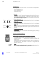
Key to symbols
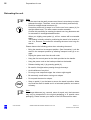
Different symbols used in this manual draw your attention to safety aspects and useful tips. These symbols are explained in the following.
Warning!
The warning triangle indicates potential sources of danger which may
constitute a risk of injury for the user or a health hazard.
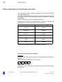
Caution:
The square indicates situations which may lead to malfunction, defects,
collision or damage of the system.
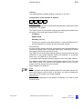
Note:
The hand indicates hints on the use of the system or other tips for the
user.
Read the user manual!
OPMI® and Pentero® are registered trademarks of Carl Zeiss Surgical
GmbH.
AutoDrape™, Superlux, FlexiTrax™, MultiVision™ and FLOW™ 800
are trademarks of Carl Zeiss Surgical GmbH.
FLOW 800 SW 2.21
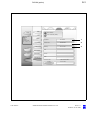
FLOW 800 software release 2.21 is not an update, but a software upgrade
for the IR800 option of OPMI Pentero for the analysis of infrared video angiography.
Upgrading is only possible for systems with serial number 6631402450
and higher and with software version 2.20.
G-30-1458-en
OPMI® Pentero® Software Release 2.20 / 2.21
Issue 11.1
Printed on 18. 02. 2009
Contents
G-30-1458-en
Software Release 2.20 / 2.21
1
–
Key to symbols
2
–
FLOW 800 SW 2.21
2
Functions at a glance
9
–
OPMI Pentero
10
–
What to do in an emergency
12
Safety
15
–
Protective measures for IT systems and networks
16
–
Notes on installation and use
17
– Risk of burn injuries caused by high
illumination intensity
23
–
Safety devices of the suspension system
26
–
Warning labels and notes
28
Description
33
OPMI Pentero
34
–
Intended use
34
–
Special properties
36
–
Surgical microscope and laser micromanipulator
38
–
Injecting video images in the surgical microscope
39
–
Injecting navigation information in the surgical microscope *)
40
–
Overall system configuration
41
–
Configuration options
44
Central user interface (touchscreen)
46
–
50
Main menu
Controls and connections
52
–
Binocular tubes and eyepieces
60
–
Handgrips
64
–
Superlux 330 illumination system
66
–
Operating principle of the additional illumination
68
OPMI® Pentero® Software Release 2.20 / 2.21
Issue 11.1
Printed on 18. 02. 2009
G-30-1458-en
–
Autofocus (focusing aid)
69
–
Drape vacuum system
70
–
Stand base /FlexiTrack™ system
72
–
Connector panel
76
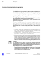
Connecting navigation systems
80
Preparations for use
85
–
86
Relocating the unit
Assembling the system
88
–
Configurations
88
–
Mounting the tube and the eyepieces
90
–
Attaching documentation / coobservation equipment
92
–
Mounting the mouth switch (option)
94
–
Adjusting the position of the handgrips
98
–
Attaching sterile drapes
100
–
Positioning the system at the operating table
102
–
Starting the system
104
–
Configuring the handgrips
106
Balancing the system
110
–
Adjusting the surgical microscope
115
–
USER menu / login
116
–
Activating IT system rights and data protection
120
–
Configuration menu (CONFIG)
124
Operation
163
Checklist
164
Procedure
167
–
Working with the surgical microscope
167
–
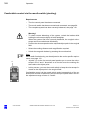
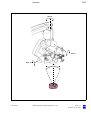
Comfortable control via the mouth switch (pivoting)
168
–
Working with the data injection system
170
Patient Files menu (PAT-FILES)
174
–
Managing patient data
174
–
Viewing patient data
186
–
Viewing patient images
188
–
Editing images
192
OPMI® Pentero® Software Release 2.20 / 2.21
Issue 11.1
Printed on 18. 02. 2009
G-30-1458-en
–
Saving
196
–
Storing patient data on CD/DVD
198
–
Storing patient data on a USB stick
202
What to do in an emergency
208
–
Illumination failure - changing the xenon lamp
208
–
Failure of the zoom function
210
–
Failure of the focusing function
211
–
Failure of the magnetic brakes
212
–
Touchscreen failure
212
–
Failure of the line voltage
212
–
Error messages in the data injection system
213
–
Failure of all control functions (Emergency mode)
214
– Individual magnetic brakes are blocked
(OPMI can not be moved at all or only to a limited extent)
215
Maintenance/Service
217
–
Trouble-shooting
218
–
Service Contract (Option)
219
–
Starting Remote Service
220
–
Changing the lamp module
222
–
Recommended cleaning method
224
–
Sterile drapes
225
–
Ordering data
226
–
Spare parts
227
–
Accessories
228
–
Disposal
230
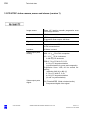
Technical data
231
–
OPMI Pentero
232
–
3 CCD PAL video camera, mono and stereo (version 1)
237
–
3 CCD NTSC video camera, mono and stereo (version 1)
238
–
3 CCD PAL video camera, mono and stereo (version 2)
239
–
3 CCD NTSC video camera, mono and stereo (Version 2)
240
–
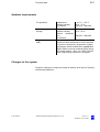
Ambient requirements
241
–
Changes to the system
241
OPMI® Pentero® Software Release 2.20 / 2.21
Issue 11.1
Printed on 18. 02. 2009
G-30-1458-en
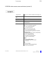
Digital video recording (option)
243
Digital video recording (option)
244
–
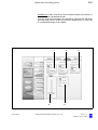
Description
244
–
Video clips
248
–
Editing video clips
250
–
Merging video clips
256
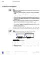
INFRARED 800 fluorescence module
(option)
261
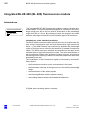
Integrated INFRARED 800 (IR 800) fluorescence module
262
–
Intended use
262
–
Description
266
–
Connecting an external monitor (recommended option)
276
–
INFRARED 800 settings before every surgical procedure
278
–
Checklist for the IR 800 function test
279
Procedure
280
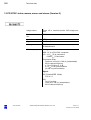
FLOW 800 (option)
287
Normal use
288
Description
292
–
General configuration
292
–
Configuring INFRARED 800
296
–
Activating FLOW 800
298
–
Description of INFRARED 800
300
–
Description of FLOW 800
306
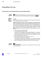
Preparations for use
318
–
Connecting an external monitor (recommended option)
318
–
INFRARED 800 settings before every surgical procedure
320
–
Checklist for the IR 800 function test
321
Procedure
322
–
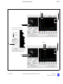
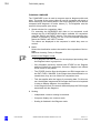
SETUP phase
322
–
RECORD phase
324
–
PLAYBACK phase
326
–
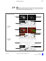
FLOW 800 processing phase
328
OPMI® Pentero® Software Release 2.20 / 2.21
Issue 11.1
Printed on 18. 02. 2009
BLUE 400 fluorescence module (option)
339
Integrated BLUE 400 (BL 400) fluorescence module
340
–
Intended use
340
–
Description
344
BL 400 checklist
348
DICOM (option)
351
DICOM
352
–
Intended use
352
–
Conformance Statement
352
–
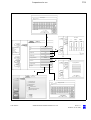
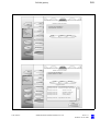
Configuring the network connection
356
–
Further information on the Ethernet connection
362
–
Connection test
364
–
Configuring the DICOM connection
366
–
Adding, editing and deleting a DICOM server
366
–
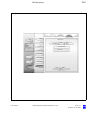
Configuring the DICOM function
368
–
Defining the maximum video export size to network servers
372
–
Error messages during system configuration
376
–
Importing patient data sets (from RIS systems)
378
–
Importing patient data sets (from PACS system)
380
–
Loading patient data
382
–
Exporting DICOM data to a PACS
390
HDTV camera system (option)
(option)
393
393
G-30-1458-en
HDTV camera system for OPMI Pentero (option)
394
–
Intended use
394
–
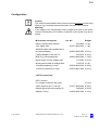
Configuration
395
–
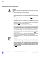
Attaching the HDTV components
396
–
Connecting the HDTV camera system
398
–
Microscope positions with the HDTV camera system
400
Checklist for HDTV camera system for OPMI Pentero
401
Cleaning the HDTV components
403
OPMI® Pentero® Software Release 2.20 / 2.21
Issue 11.1
Printed on 18. 02. 2009
Index
G-30-1458-en
OPMI® Pentero® Software Release 2.20 / 2.21
405
Issue 11.1
Printed on 18. 02. 2009
9
Functions at a glance
Functions at a glance
G-30-1458-en
OPMI Pentero
10
What to do in an emergency
12
OPMI® Pentero® Software Release 2.20 / 2.21
Issue 11.1
Printed on 18. 02. 2009
10
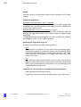
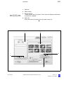
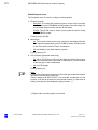
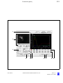
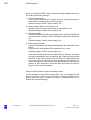
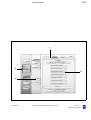
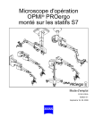
Functions at a glance
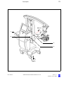
OPMI Pentero
1
2
3
4
5
6
7
8
9
10
11
12
13
14
15
16
17
18
19
20
21
22
23
24
25
26
27
28
29
30
31
32
33
G-30-1458-en
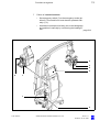
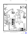
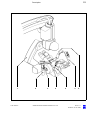
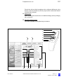
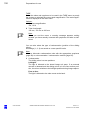
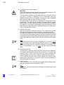
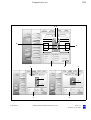
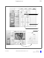
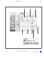
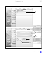
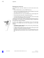
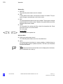
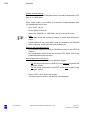
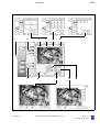
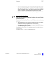
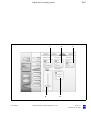
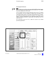
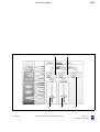
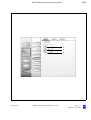
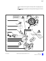
Adjusting the microscope
Programmable button (factory setting: illumination +)
Programmable button (factory setting: illumination -)
Setting focus +/- (configurable: setting zoom +/-)
Setting zoom +/- (configurable: setting focus +/-)
Joystick: moving the OPMI in the XY direction
Programmable button (factory setting: autofocus)
Programmable button (factory setting: trigger photo)
Unlocking/locking magnetic brakes for selected axes (SB)
Unlocking/locking magnetic brakes for all axes (AB)
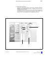
Connecting USB storage media
Changing the xenon lamp / lamp module
CD/DVD drive
Connecting an external navigation system
page:115, 124ff
page:108, 136
page:108, 136
page:108, 136
page:108, 136
page:136, 140
page:108, 142
page:106, 136
page:108, 142
page:106, 142
page:200ff
page:208, 222
page:196
page:78, 80ff,
154
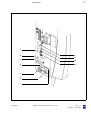
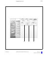
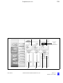
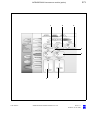
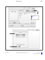
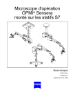
Connecting a LAN cable
page:78
Connecting a modem
page:78
Connecting a foot rocker switch
page:78
AUX port for controlling an external device
page:78, 234
Connecting a foot control panel, foot switch or operating chair page:78
Automatic circuit breakers
page:78
Emergency switch (remove cover)
page:200
Rated voltage indicator
page:76
Power outlet
page:76
Power inlet (115/230V)
page:76
Video input port (e.g. for connecting an endoscope camera) page:78
Video signal output port BNC (VBS)
page:76, 276
Video DV output port
page:76
Connecting an external monitor (VGA/RGB)
page:76
Connecting an external monitor (Y/C)
page:76, 276
Connecting the system to potential equalization
page:76
Power switch; powering up the system
page:76
Locking pedal - press to lock stand in position
page:74, 86
Setting straight-ahead travel
page:74 ,86
OPMI® Pentero® Software Release 2.20 / 2.21
Issue 11.1
Printed on 18. 02. 2009
11
Functions at a glance
13
12
18 17
11
16 15
10
9
8
7
6
5
4
3
2
1
14
19
20
21
25
26
22
27
28
29
30
23
31
24
STOP 32
G-30-1458-en
OPMI® Pentero® Software Release 2.20 / 2.21
33
Issue 11.1
Printed on 18. 02. 2009
12
Functions at a glance
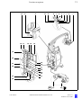
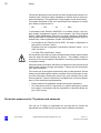
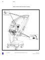
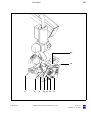
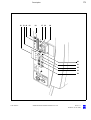
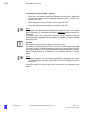
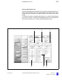
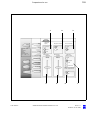
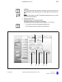
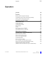
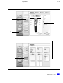
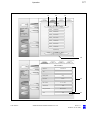
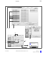
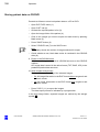
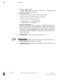
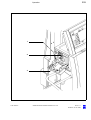
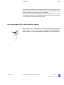
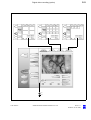
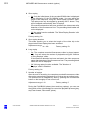
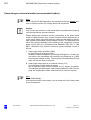
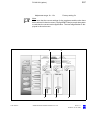
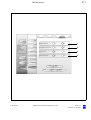
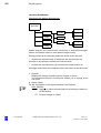
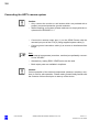
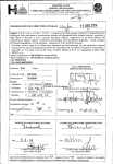
What to do in an emergency
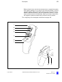
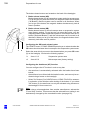
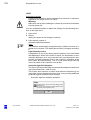
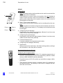
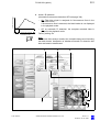
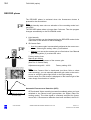
1
Failure of illumination - changing the xenon lamp:
•
2
Open flap (1)
• Change the xenon lamp by pulling grip (8)
Failure of the zoom function:
page 208
•
3
Manually adjust the magnification using zoom knob
(2). If the motorized zoom function becomes active of
its own accord (e.g. travels to the stop), set emergency
switch (7) to the emergency mode (position 2).
page 210
Failure of the focusing function:
•
4
Manually adjust the working distance using focusing
knob (3). If the motorized focusing function becomes
active of its own accord (e.g. travels to the stop), set
the emergency switch to the emergency mode (position 2)
page 211
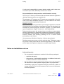
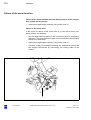
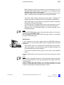
Some of the magnetic brakes are blocked:
•
Switch off power switch (4). As soon as the blue
screen appears (approx. 10 sec), switch the system
back on.
The OPMI functions (zoom, focus, light and magnetic
brakes) are available again after approx. 15 seconds.
The computer and touchscreen, however, are disabled.
If the magnetic brakes are still blocked:
•
5
Hold the microscope on its body (not on the handgrips)
and position it manually by overcoming the braking effect.
page 215
Failure of the touchscreen:
•
6
Do not under any circumstances touch the touchscreen, since this can result in changes to settings and
parameters. Zoom, focus, illumination and brakes can
still be operated.
page 212
Error messages in the data injection system:
•
G-30-1458-en
System errors are displayed in the microscope's integrated data injection system. You can delete these
messages by acknowledgement using the joystick of
the right handgrip (pushbutton) or the touchscreen.
page 212
OPMI® Pentero® Software Release 2.20 / 2.21
Issue 11.1
Printed on 18. 02. 2009
13
Functions at a glance
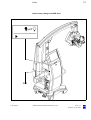
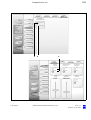
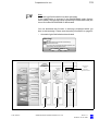
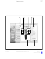
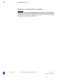
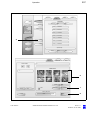
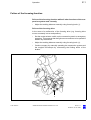
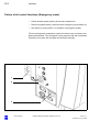
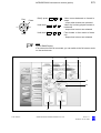
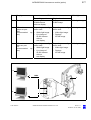
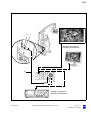
7
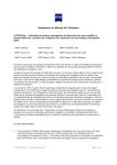
Failure of control functions:
•
Set emergency switch (7) to the emergency mode (position 2). Zoom and focus must then be operated manually (2, 3).
•
Hold the microscope on its body (not on the handgrips)
and position it manually by overcoming the braking effect.
page 214
6
3
2
5
8
1
7
4
G-30-1458-en
OPMI® Pentero® Software Release 2.20 / 2.21
Issue 11.1
Printed on 18. 02. 2009
14
Functions at a glance
G-30-1458-en
OPMI® Pentero® Software Release 2.20 / 2.21
Issue 11.1
Printed on 18. 02. 2009
Safety
15
Protective measures for IT systems and networks
16
Notes on installation and use
17
Risk of burn injuries caused by high
illumination intensity
23
Safety devices of the suspension system
26
Warning labels and notes
28
Safety
G-30-1458-en
OPMI® Pentero® Software Release 2.20 / 2.21
Issue 11.1
Printed on 18. 02. 2009
16
Safety
The device described in this manual has been designed and tested in accordance with Carl Zeiss safety standards as well as German and international standards. This guarantees a high degree of instrument safety.
The system described in this user manual has been designed in compliance with the requirements of:
–
EN
–
IEC
–
UL
– CSA
In accordance with Directive 93/42/EEC for medical devices, the complete quality management system of the company Carl Zeiss Surgical
GmbH, 73446 Oberkochen, Germany, has been certified by DQS Deutsche Gesellschaft zur Zertifizierung von Managementsystemen GmbH, a
notified body, under registration number 250758 MP23.
–
In compliance with Directive 93/42 /EEC, the basic configuration of
this system is a class I device.
Equipped with the Integrated Fluorescence Module option, it is a
class IIa device.
–
For USA: FDA classification: Class I.
We would like to provide you with information about safety aspects which
must be observed when handling this device. This chapter contains a
summary of the most important information concerning matters relevant
to instrument safety.
Important safety information has been incorporated in this manual and is
marked with a warning triangle accordingly. Please give this information
your special attention.
The correct use of the system is absolutely vital for safe operation. Please
make yourself totally familiar with the contents of this manual prior to startup of the instrument. Please also observe the user manuals of any additional equipment. Further information is available from our service department or from authorized representatives.
•
Please observe all applicable accident prevention regulations.
•
The instrument must be connected to a special emergency backup
line supply in accordance with the regulations or directives which apply in your country.
Protective measures for IT systems and networks
The user (or IT officer) is responsible for ensuring that no viruses are
transferred to the OPMI Pentero system via the network connection.
G-30-1458-en
OPMI® Pentero® Software Release 2.20 / 2.21
Issue 11.1
Printed on 18. 02. 2009
17
Safety
It is the user's responsibility to ensure that the media used for data communication (CD, DVD, USB stick) are free from viruses.
Responsibilities for data protection and information security
The user (or IT officer) must ensure that the national laws and regulations
relating to data protection are complied with.
The operators of IT systems and IT networks are responsible for the definition of the safety standards required, i.e. for the creation of the necessary technical and organizational framework.
Definition of terms
Personal data means any information concerning the personal or material
circumstances of an identified or identifiable individual. All data directly attributable to a person (employee, customer, supplier), e.g. marital status,
type of employment, religion, income, etc., must be protected.
Data processing means the storage (entry, recording or preservation),
transfer (transmission to third parties outside the organization), modification (alteration of the substance, including anonymization and aliasing),
erasure (deletion) and blocking (labeling so as to restrict further
processing or use) of data.
Use means any utilization of data (e.g. in-house transmission).
Recipient means any person or body receiving data. Third party means
any person or body other than the controller (legal entity). The transmission of data to third parties is deemed to constitute data transfer.
Notes on installation and use
Safe working order
•
G-30-1458-en
Do not operate the equipment contained in the delivery package in
–
explosion-risk areas,
–
the presence of inflammable anesthetics or volatile solvents such
as alcohol, benzine or similar chemicals.
•
Do not station or use the instrument in damp rooms. Do not expose
the instrument to water splashes, dripping water or sprayed water.
•
Immediately unplug any equipment that gives off smoke, sparks or
strange noises. Do not use the instrument until our service representative has repaired it.
OPMI® Pentero® Software Release 2.20 / 2.21
Issue 11.1
Printed on 18. 02. 2009
18
Safety
•
Do not place any fluid-filled containers on top of the instrument. Make
sure that no fluids can seep into the instrument.
•
Do not force cable connections. If the male and female parts do not
readily connect, make sure that they are appropriate for one another.
If any of the connectors are damaged, have our service representative
repair them.
•
Potential equalization: If requested, the instrument can be incorporated into potential equalization measures.
•
Do not use a mobile phone in the vicinity of the equipment because
the radio interference can cause the equipment to malfunction. The effects of radio interference on medical equipment depend on a number
of various factors and are therefore entirely unforeseeable.
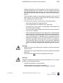
Warning!
Do not use the video images for diagnostic purposes, as the video cameras and the monitor have not been calibrated. The visualized images
may therefore include deviations in shape, contrast and color.
The company Carl Zeiss shall not be liable for any defective CD/DVD and
any resultant loss of images.
•
If you have burnt important images on a CD/DVD, we recommend you
to create a backup of this CD/DVD using a PC.
Caution:
The company Carl Zeiss accepts no liability for any loss of patient, image
and video data as well as system or user-specific configuration data. If required, arrange for patient, image and video data as well as all system
settings to be backed up by your IT administrator on a regular basis.
In the event of repairs by Carl Zeiss service staff, the recovery of patient,
image, video and configuration data is no longer possible.
G-30-1458-en
•
Modifications and repairs on these instruments or instruments used
with them may only be performed by our service representative or by
other authorized persons.
•
The manufacturer will not accept any liability for damage caused by
unauthorized persons tampering with the instrument; this will also forfeit any rights to claim under warranty.
•
Over longer distances (e.g. removal, return for repair, etc), the instrument may only be transported in the original packaging or in special
return packaging. Please contact your dealer or the Carl Zeiss service
team.
•
Use this instrument only for the applications described.
OPMI® Pentero® Software Release 2.20 / 2.21
Issue 11.1
Printed on 18. 02. 2009
19
Safety
•
Only use the instrument with the accessories supplied. Should you
wish to use other accessory equipment, make sure that Carl Zeiss or
the equipment manufacturer has certified that its use will not impair
the safety of instrument.
•
Only personnel who have undergone training and instruction are allowed to use this instrument. It is the responsibility of the customer or
institution operating the equipment to train and instruct all staff using
the equipment.
•
Keep the user's manuals where they are easily accessible at all times
for the persons operating the instrument.
•
Never look at the sun through the binocular tube, the objective lens or
an eyepiece.
•
Please do not pull at the power cable or any other connecting cables.
•
This system is a high-grade technological product. To ensure optimum performance and safe working order, we recommend having the
system checked by our service representative on a regular basis.
If a failure occurs which you cannot correct with the help of this user
manual, attach a sign to the system stating that it is out of order and
contact our service representative.
•
Observe the labels showing the symbol "Risk of crushing“!
Notes on EMC (electromagnetic compatibility)
The system meets the EMC requirements of IEC 60601-1-2. During use
of the system, the precautionary measures concerning EMC listed below
must be observed.
Only use accessories that have been approved by Carl Zeiss for this
system.
Do not use any portable or mobile high frequency communication devices
in the vicinity of the system, as this may lead to an impairment of its function.
The system complies with the limits for a Class A device concerning radio
frequency emission. However, the possibility of interference to high frequency receiving devices (e.g. TV sets or radios) being used in the surroundings cannot be ruled out. If interference of this type occurs, please
inform your Carl Zeiss Service.
G-30-1458-en
OPMI® Pentero® Software Release 2.20 / 2.21
Issue 11.1
Printed on 18. 02. 2009
20
Safety
Interference radiation
To ensure permissible operation in conjunction with neuromonitoring systems, an optional upgrade kit is available which significantly reduces the
system's permissible interference radiation for these sensitive measurements (see Accessories, neuromonitoring upgrade kit, page 229)
Requirements for operation
–
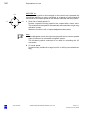
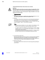
Note:
Please also take note of the latest Release Notes about the installed
software version. These are part of the delivery package when the
system is supplied. After a software update, you will always receive
the latest version.
Our service representative or a specialist authorized by us will install the
instrument. Please make sure that the following requirements for operation remain fulfilled in the future:
–
All mechanical connections (details in the user's manual) which are
relevant to safety are properly connected and screw connections tightened.
–
All cables and plugs are in good working condition.
–
The instrument is plugged into a power outlet which has a properly
connected protective ground contact.
–
The power cord being used is the one designed for use with this instrument.
Warning!
For safety reasons, the system must only be used when correctly balanced. Despite the autobalance function, it may happen in exceptional
cases that the surgical microscope is not correctly balanced.
With an incorrectly balanced system, brake release may lead to uncontrolled movements of the suspension system. For this reason, the balancing procedure and the subsequent test must not be performed above
the patient and only at a safe distance from other persons and instruments.
To check correct balancing of the system, loosen the brakes while holding
the microscope tightly at both handgrips. If the system has been correctly
balanced, the surgical microscope can be moved almost effortlessly.
Repeat the autobalance procedure, if required.
G-30-1458-en
OPMI® Pentero® Software Release 2.20 / 2.21
Issue 11.1
Printed on 18. 02. 2009
21
Safety
Connection to data networks
Activities in the data network may interfere with the system. We therefore
recommend that you disconnect the system from data networks before
surgery.
The network connector must be adequately contact-protected, e.g. made
of plastic material.
The cable and connector of the network connection must at least comply
with Cat-5e EIA/TIA-568A-5, i.e. the more recent Class D values from
ISO/IEC 11801:2002 or EN 50173-I:2002.
Warning!
Data transmitted by the system into the data network or data available in
the data network risk to be corrupted or transmitted incompletely. Therefore, no liability can be accepted for the correctness of the data.
The operator of the data network is responsible for compliance with the
legal requirements regarding data security and for the protection of personal rights.
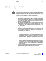
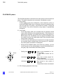
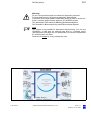
Connection of equipment from other manufacturers
If you operate this system within the patient area* in conjunction with devices from other manufacturers which do not comply with the IEC606011 standard, you must ensure that either the third-party devices are powered via an isolating transformer, or that each of them is connected with
the central ground system via an additional ground terminal (potential
equalization).
The leakage current may increase if the system is connected with other
devices. The resulting new system must comply with the EN 60601-1-1
standard (Safety Requirements for Medical-Electrical Systems).
R
G-30-1458-en
OPMI® Pentero® Software Release 2.20 / 2.21
R
1.
5
59 m
"
*Fig.: Patient area
Issue 11.1
Printed on 18. 02. 2009
22
Safety
Before every use and after re-equipping the instrument
•
Make sure that all ”Requirements for operation” are fulfilled.
•
Go through the checklist (see chapter "Operation“ or the index).
•
Re-attach or close any covers, panels or caps which have been removed or opened.
•
Please pay special attention to labels on the unit (warning triangle with
an exclamation mark, warning labels and notes).
•
Do not cover any ventilation openings.
For every use of the instrument
•
Using the locking pedal on the base, secure the stand in position.
Make sure that the stand is stable and cannot roll away.
•
Make sure that nothing obstructs the touch-sensitive area of the
touchscreen. Prevent objects from exerting pressure on the touchsensitive area of the touchscreen.
•
Any kind of radiation has a detrimental effect on biological tissue.This
also applies to the light illuminating the surgical field. Please therefore
reduce the brightness and duration of illumination on the surgical field
to the absolute minimum required.
•
Never use xenon illumination for ophthalmic procedures.
•
Make sure that no xenon light enters the patient's eyes.
•
The illumination intensity required depends on the type of application
involved. Make sure that no tissue damage is caused by excessive illumination intensity.
Connection and operation of navigation systems
Only systems from authorized manufacturers may be connected and
used on the navigation interface of OPMI Pentero (see page 80). Authorized manufacturers are companies or institutions with which Carl Zeiss
Surgical has concluded an Open Interface Contract and for which the use
of the integrated navigation interface with data injection system has been
licensed.
Please observe the user manual for the connected system.
G-30-1458-en
OPMI® Pentero® Software Release 2.20 / 2.21
Issue 11.1
Printed on 18. 02. 2009
23
Safety
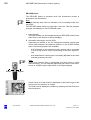
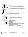
Risk of burn injuries caused by high
illumination intensity
General
The OPMI Pentero is equipped with a powerful xenon illumination system.
Excessive illumination intensities may lead to third-degree burns, if used
improperly.
The risk of burns is influenced by several different factors:
System-related factors:
–
The wavelength range is limited by filters to the visible range between
400 nm and 700 nm (between 400 nm and 780 nm in the IR 800 mode
only). These filters remain stable over a very long period of time and
cannot be exchanged by the user.
–
With increasing age of the light source, the actual illumination intensity
delivered at the respective setting decreases. When the light source
is finally replaced, the illumination intensity increases again to the
high, original value.
Surgery-related factors:
G-30-1458-en
–
The selected intensity of the light source is a major factor for the risk
of injury. It should always be set to the minimum required for the surgical procedure to be performed.
–
The size of the illuminated field influences the risk of injury in two different ways:
–
If the illuminated area has a large diameter, skin areas are illuminated that are not closely monitored by the surgeon and are not
sufficiently irrigated. These areas are particularly prone to injury.
Injuries can be prevented by adjusting the diameter of the illuminated field to the smallest size needed for the respective procedure.
–
Reducing the illuminated field increases the intensity because the
light becomes more focused. The light intensity should therefore
be reduced, if possible, as soon as the diameter of the illuminated
area is reduced.
–
A long surgical procedure increases the risk of injury, in particular if a
standard procedure takes considerably longer than usual.
–
Injuries in the peripheral area can be prevented by covering this area
with wet, sterile gauze.
OPMI® Pentero® Software Release 2.20 / 2.21
Issue 11.1
Printed on 18. 02. 2009
24
Safety
–
You should also take into account that some areas of the body may be
more sensitive than others.
–
Certain preparations of the surgical field, local vasoconstrictive medications and incision drapes may also result in a higher risk of injury.
Patient-related factors:
–
The general condition of a patient's health may contribute to the risk
of injury.
–
The skin type may also play a major role in this respect.
–
Certain medications affect the sensitivity to light.
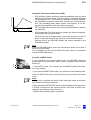
Recommendations
Due to the large number of different factors involved and the lack of scientific publications on this topic, Carl Zeiss cannot provide guidance on
acceptable intensities and exposure durations. However, the OPMI
Pentero has several features that can help the user to reduce the risk of
burns:
G-30-1458-en
–
The start value of the light intensity can be set to a low value (page
134).
–
The spot function permits you to reduce the size of the illuminated field
to the area observed during the procedure (page 66).
–
You can then set the light intensity to the value required for the procedure using the buttons on the handgrip or foot control panel. Please
note that the use of the spot illumination system increases the intensity as the size of the illuminated field decreases. Therefore adjust the
light intensity after changing the diameter of the illuminated field.
–
If the system features Automatic Light Field Limitation, this function
has been activated at the factory and should not be deactivated.
In systems without automatic light field limitation, the Light Intensity
Control function has been activated at the factory and should not be
deactivated.
–
The magnification level is usually increased during a procedure, leading to a darker image and thus necessitating an increase in illumination intensity. If zoom-dependent brightness control has been
activated, it automatically compensates for this loss in image brightness. (page 134)
–
Switch off the light when the microscope is not used, and make sure
that it is not pointed at unprotected bare skin.
OPMI® Pentero® Software Release 2.20 / 2.21
Issue 11.1
Printed on 18. 02. 2009
25
Safety
Please note that most burns affected the skin around the incision. The
most important measures to prevent burns are the reduction of the area
illuminated by spot illumination and covering the peripheral area with wet
sterile gauze. The area of the incision should be constantly irrigated.
Final remark
Carl Zeiss recommends:
–
Reduce the illumination of the surgical field to the extent required for
the patient's safety and for clear microscopic visualization.
The illumination intensity is preconfigured (factory settings) in such a
way that a warning is displayed on the touchscreen and in the data injection system when the threshold value of 25% is exceeded, informing the user of possible tissue damage when the light intensity is too
high.
–
Please note the warning and safety notes in the "Light“ configuration
menu (page 134).
–
Reduce the exposure time to a minimum.
These measures should help the surgeon to reduce the risk of phototoxic
injury of the patient.
After every use of the instrument
•
G-30-1458-en
Switch off the system at the power switch after every use.
OPMI® Pentero® Software Release 2.20 / 2.21
Issue 11.1
Printed on 18. 02. 2009
26
Safety
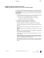
Safety devices of the suspension system
Mechanical end stops
protect cables and the light guide against bending and stretching.
Transport locks (1)
for locking the axes in position during transportation.
Safety switch
The brakes will be locked if a spring or cable breaks. You can nevertheless finish surgery, as you can still move the surgical microscope by applying slight force.
Uninterruptible power supply (UPS)
A UPS is integrated in the system to ensure correct operation in the event
of short power failure. It powers the electronic system and the touchscreen, but not the light source.
Messages:
– Line power failure: in the event of line power failure, the system is
supplied for a short time. If no power is available for a prolonged
period, the system is shut down.
– Line power is back: the user is informed when line power is back
(Power OK), and all subsystems are re-initialized. This process
may take a few seconds.
Note:
In general, the system is ready for operation after power-up. A continuous
beep indicates extreme discharging of the USP. In this case, the system
should not be powered up for at least five minutes. After this time, you can
power up the system again for charging the UPS. For the initial startup or
after long rest periods, we recommend the following: leave the poweredup system connected to line power for approx. 12 hours in order to fully
charge the UPS.
The system automatically tries to remedy problems in the control software. After several unsuccessful attempts, the system executes a PC
reset to restart the application. This restart runs automatically in the background and restores the full functionality of the system within approx. 2
minutes. All major basic functions of the OPMI Pentero remain fully available to the user during this time (operation of focus, zoom, light, brakes,
motorized XY movement).
Backup illumination
The lamp module contains two identical lamps. If lamp 1 fails, a quick-action changer ensures that the light guide is supplied by lamp 2. The lamp
change does not impair the surgeon in his work.
G-30-1458-en
OPMI® Pentero® Software Release 2.20 / 2.21
Issue 11.1
Printed on 18. 02. 2009
27
Safety
Heat protection filter
The illumination system is equipped with a heat protection filter.
1
1
1
G-30-1458-en
OPMI® Pentero® Software Release 2.20 / 2.21
Issue 11.1
Printed on 18. 02. 2009
28
Safety
Warning labels and notes
OP
M
IP
en
te
ro
Caution:
Observe all warning labels and notes!
If any label is missing on your instrument or has become illegible, please
contact us or one of our authorized representatives. We will supply the
missing labels.
Laser
Austrittsöffnung
Laser
Aperture
Apertura
de Laser
Ouverture
Laser
G-30-1458-en
OPMI® Pentero® Software Release 2.20 / 2.21
Issue 11.1
Printed on 18. 02. 2009
29
Safety
DRAPE
Hier luftdicht abschließen
Make airtight here
Fermer hermétiquement ici
Cerrar herméticamente aquí
OP
MI
Pe
nte
ro
OP
P
MI
o
ter
en
Options:
Carl Zeiss Surgical GmbH
SN 10xxxx
FLOW 800 Pentero
REF 302581-9250-000
Carl Zeiss Surgical GmbH
SN 51xxxx
INFRARED 800 NTSC
REF 302581-9246-000
Carl Zeiss Surgical GmbH
SN 51xxxx
INFRARED 800 PAL
REF 302581-9245-000
Carl Zeiss Surgical GmbH
Laserstrahlung
nicht in den Strahl
blicken
SN 50xxxx
BLUE 400
REF 302581-9050-000
Laser Klasse 2
nach EN 60 825-1:2002
Pmax: <1mW λ 635-645nm
Radiacion Laser
no mirar en
el rayo
Laser de classe 2
sequm EN 60 825-1:2002
Pmax: <1mW λ 635-645nm
Laser radiation
do not stare
into beam
Class 2 laser product
as per EN 60 825-1:2002
Pmax: <1mW λ 635-645nm
FABRIQUE EN R. F. A. PAR
Carl Zeiss
Rayonnement Laser
ne pas regarder
dans le faisceau
Appareil a laser de classe 2
conforme a EN 60 825-1:2002
Pmax: <1mW λ 635-645nm
MANUFACTURED IN GERMANY BY
Carl Zeiss
Laser radiation
do not stare into beam
Power output 1 mW
wavelength 635-645 nm
class II laser product
G-30-1458-en
OPMI® Pentero® Software Release 2.20 / 2.21
Issue 11.1
Printed on 18. 02. 2009
30
Safety
Labels: transport locks and risk of crushing
G-30-1458-en
OPMI® Pentero® Software Release 2.20 / 2.21
Issue 11.1
Printed on 18. 02. 2009
31
Safety
Labels: lamp change and DVD drive
DVD
G-30-1458-en
OPMI® Pentero® Software Release 2.20 / 2.21
Issue 11.1
Printed on 18. 02. 2009
32
Safety
G-30-1458-en
OPMI® Pentero® Software Release 2.20 / 2.21
Issue 11.1
Printed on 18. 02. 2009
Description
33
OPMI Pentero
34
Intended use
34
Special properties
36
Surgical microscope and laser micromanipulator
38
Injecting video images in the surgical microscope
39
Injecting navigation information in the surgical microscope *)
40
Overall system configuration
41
Configuration options
44
Central user interface (touchscreen)
46
Main menu
50
Controls and connections
52
Binocular tubes and eyepieces
60
Handgrips
64
Superlux 330 illumination system
66
Operating principle of the additional illumination
68
Autofocus (focusing aid)
69
Drape vacuum system
70
Stand base /FlexiTrack™ system
72
Connector panel
76
Connecting navigation systems
80
Description
G-30-1458-en
OPMI® Pentero® Software Release 2.20 / 2.21
Issue 11.1
Printed on 18. 02. 2009
34
Description
OPMI Pentero
Intended use
The overall system comprises a surgical microscope and a floor stand
containing the electronics and a graphic touchscreen with video display.
The OPMI Pentero is ideally suited for cranial and spinal applications in
neurosurgery, for ENT applications in the area of the auditory nerve and
the base of the skull. Further fields of application include R&P procedures
in accident surgery, R&P surgery, and oral and maxillo-facial surgery. The
system is also ideally suited for multidisciplinary use in microsurgery. It
has also been designed for surgical procedures in which an endoscope
and a surgical microscope are used simultaneously. The system is
equipped for the connection of navigation systems and for data communication with external network systems.
The system is intended for use in hospitals, clinics or other human medicine institutions.
The functions of the surgical microscope and of the suspension system
are controlled by the central control unit in the console. An interactive
graphic touchscreen permits you to configure all settings. You can trigger
these functions using the buttons on the handgrips or on a foot control
panel.
The system must only be operated by physicians, nurses and other medically trained OR staff who have received appropriate briefing and observe the instructions of the user's manual. The installation conditions and
the use of the system must meet microsurgical requirements:
–
low vibration
–
dust-free environment
–
level, horizontal positioning
–
avoidance of extreme mechanical stress.
Warning!
– In line with its intended use, the system must only be used on a patient
when it has been correctly balanced.
With an incorrectly balanced system, brake release may lead to uncontrolled movements of the suspension system. For this reason, the
balancing procedure and the subsequent test must not be performed
above the patient and only at a safe distance from other persons and
instruments.
G-30-1458-en
OPMI® Pentero® Software Release 2.20 / 2.21
Issue 11.1
Printed on 18. 02. 2009
35
Description
–
–
–
The system must not be used for ophthalmic procedures.
Note:
The system is not intended for permanent data archiving. You can use
CDs/DVDs, a USB stick or an external hard drive for data backup. All
users are responsible for archiving their own data.
If sufficient storage space is no longer available, the system informs
you that files no longer required should be archived or deleted.
Data can be deleted by every subsequent user!
Note:
Please also take note of the latest Release Notes about the installed
software version. These are part of the delivery package when the
system is supplied. After a software update, you will always receive
the latest version.
Note on MediLive Video Tools:
The MediLive Video Tools software provides improved compatibility between your PC (Windows™ or MacOS™) and the video DVDs created
with OPMI® Pentero®.
Please install MediLive Video Tools on your PC if you notice the following
problems:
–
The computer cannot read the DVD content or the DVD is not identified because the UDF 2.0 disk format is not recognized.
–
The video player or Office™ software is unable to play MPEG2 videos
as the MPEG2 decoder is missing.
One MediLive Video Tools CD is supplied as part of the digital video recording option.
The ZEISS cat. no. of this CD is 308203-8040-000.
G-30-1458-en
OPMI® Pentero® Software Release 2.20 / 2.21
Issue 11.1
Printed on 18. 02. 2009
36
Description
Special properties
G-30-1458-en
–
The surgical microscope features an integrated beamsplitter system
which can be set on the touchscreen (page 130) or on the microscope
(manual setting of sliding mirror position; page 54) either as a symmetric optical system for face-to-face use, or for lateral coobservation and
documentation.
–
An autofocus system can be optionally used to focus the microscope
on an object within a working distance of 200 to 500 mm.
–
The autofocus system focuses on the object at the press of a button
on the handgrip or foot control unit, in combination with the brake buttons. The point of reference is the center of the field of view. If the object is in focus, the focus is visualized by two laser spots which meet
in the optical axis at the center of the field of view.
–
The magnification ratio of the zoom system is 1:6.
–
The system provides an image illuminated with optimum brightness,
maximum image contrast and additionally switchable, special illumination for lightening up shadows in narrow channels. An integrated diaphragm permits the depth of field to be set to two levels.
–
Filters can be automatically swung into the observation and video
beam paths (for special applications such as fluorescence (option)).
–
A high-grade 3-chip camera is integrated in the surgical microscope.
An additional camera for the stereo mode can be retrofitted at any time
by our service representative.
–
The surgical microscope is equipped with a fully integrated, digital
data injection system for navigation, video, PC, etc. (Multivision system).
–
The system is equipped for the connection of a navigation system.
–
Video image injection combines endoscopy with classical microscope technology.
–
Quick image switchover between the microscope image and the endoscope image using a handgrip button or foot control unit, making it
unnecessary for the surgeon to look up from the surgical field.
–
Video signal output: what the surgeon currently sees is visualized on
an external monitor.
–
Display of operating mode: every time you press the handgrip button or the foot control unit, the current mode is displayed for 5 seconds
in the form of text information superimposed on the current image.
OPMI® Pentero® Software Release 2.20 / 2.21
Issue 11.1
Printed on 18. 02. 2009
37
Description
–
Use in a navigation system *) possible via the navigation interface.
–
Image superimposition for navigation purposes *): contours are
superimposed on the current video image.
–
Image injection for navigation purposes *)
–
Control of the graphic user interface, display of the touchscreen, control via the joystick mouse.
*) Only possible if a navigation system has been connected.
–
The system can be connected to an existing hospital network for the
transfer or exchange of data (images, videos, audio files).
–
The video images are visualized on the integrated color display, and
are visible in both eyepieces of the surgical microscope. The microscope image is eclipsed by a shutter system for this purpose.
–
At the press of a button (using the programmable handgrip button
(Multivision function) or the foot switch), the integrated shutter permits
rapid switching between the microscope image and the video image.
This means that the surgeon can observe the endoscope image in the
eyepiece and need not look at an external monitor.
–
The coobservation and documentation equipment of the surgical microscope always provides the image seen by the surgeon.
–
The touchscreen or an external monitor also displays the image currently seen by the surgeon. This is either the microscope image recorded by the integrated camera of the surgical microscope, or - after
switchover - the image provided by a connected endoscope camera.
–
An additional tiltable tube (option) can be mounted in a 180° position
to the tube for the main surgeon, allowing two surgeons to work faceto-face.
–
Important functions such as focusing and zoom have been motorized
and can be controlled by the press of a button on the programmable
handgrips.
Warning!
When connecting instruments from other manufacturers, make sure that
safety is guaranteed regarding admissible ground leakage currents. The
admissible limit value of the ground leakage current present in the suspension system's power cord is 500 µA in compliance with EN60601-1/
IEC 601-1. This value must not be exceeded. CSA NRTL certification in
compliance with UL 2601-1 only allows a maximum ground leakage current of 300 µA.
G-30-1458-en
OPMI® Pentero® Software Release 2.20 / 2.21
Issue 11.1
Printed on 18. 02. 2009
38
Description
Surgical microscope and laser micromanipulator
A Zeiss MM6 micromanipulator can be attached to the surgical microscope via the dovetail mount on the bottom of the microscope to permit
the use of a laser. Micromanipulators from other manufacturers can be
connected, but not electronically controlled.
Note:
For the OPMI Pentero, only CZ MM6 micromanipulators carrying the label
"Adjusted for OPMI Neuro" may be used.
Adjusting the surgical microscope and laser micromanipulator to
the same focal plane
The OPMI Pentero is equipped with a motorized Varioskop zoom system
which is operated via the focus rocker switches of the handgrips (Pos. 4/
5, see page 64) or the focus buttons on the foot control panel (Pos. 5/6,
see page 138).
The Varioskop is used for the motorized setting of the working distance
(coarse focus) and the motorized adjustment of image definition (fine
focus). The focus rocker switches allow you to continuously adjust the
working distance between 200 mm and 500 mm.
•
Set the working distance (coarse focus) to the focus value of the laser
micromanipulator. The central user interface (touchscreen) always
displays the focus value currently set.
•
Use the previously described, recommended procedure to check that
the focal planes coincide.
•
If necessary, correct the focus by appropriate minor adjustment (fine
focus).
The Focus Stop function (Pos. 2 page 124) permits you to deactivate the
electrical drive of the focusing system. The focus rocker switches are disabled. This prevents the focal plane setting from being inadvertently
changed by motorized movement. If Focus Stop has been activated, no
autofocus setting is performed when the brakes are operated, even if the
autofocus has been switched on.
G-30-1458-en
OPMI® Pentero® Software Release 2.20 / 2.21
Issue 11.1
Printed on 18. 02. 2009
39
Description
Injecting video images in the surgical microscope
The system described here is also suitable for surgical procedures in
which an endoscope and a surgical microscope are used simultaneously.
Endoscopy-supported microsurgery is a frequently used surgery method,
permitting minimally invasive procedures in neurosurgery.
–
Neuroendoscopy uses special endoscopes and high-resolution video
cameras to gain visual access to the skull, brain or spine. "Looking
around the corner" is also possible.
–
The surgical microscope with its stereoscopic image provides a good
overall view of the entire surgical field. It can be securely and reliably
positioned and allows convenient operation. Coobservation and documentation equipment can be attached to the surgical microscope.
–
The integrated binocular MultiVision system makes the OPMI Pentero
the ideal instrument for video image injection.
–
The surgeon can perform the entire surgical procedure without taking
his eyes from the surgical microscope.
–
At the press of a button (using the programmed MultiVision button or
programmed button of the foot control unit), the surgeon can rapidly
switch between the microscope image and the endoscope image. The
microscope image is eclipsed by a mechanical shutter, and the video
image provided by the endoscope camera appears in both eyepieces.
–
A coobserver on the surgical microscope always sees the same image
as the surgeon.
–
The touchscreen monitor always displays the image currently seen by
the surgeon. This is either the microscope image recorded by the
camera in the surgical microscope, or - after switchover - the image
provided by the endoscope camera.
–
You can record a video and save it on the hard drive for documentation (option). The optionally integrated video recorder records exactly
what the surgeon sees, including the chronological sequence of
switchover operations.
Mode display
Every time you press the appropriately programmed MultiVision button of
the handgrip or the programmed button of the foot control unit, the current
mode is displayed for approx. 10 seconds in the form of text information
superimposed on the current image.
G-30-1458-en
OPMI® Pentero® Software Release 2.20 / 2.21
Issue 11.1
Printed on 18. 02. 2009
40
Description
When you select an input port without a valid signal, a message is displayed in the selected language for approx. 10 seconds, stating that no
valid signal is available at this input port (e.g. NO VALID VIDEO SIGNAL),
and the shutter is not activated. The shutter is only activated when it
makes sense, e.g. only when a video signal is available.
Injecting navigation information in the surgical microscope *)
The OPMI Pentero is fully prepared for the connection of navigation systems. The fully integrated, powerful binocular MultiVision system even
permits the display of information in color (contours, text, menus) in the
superimposition mode. A connected navigation system can also inject
various correlated or non-correlated data while the shutter is closed (depending on the connected navigation system).
The navigation interface is set to "active" by default. While the navigation
interface is active, the information of the navigation system is injected in
the MultiVision display. If you now press the MultiVision button programmed for navigation, the shutter is closed and only the injected navigation image is displayed. A further press of the button opens the shutter
again.
Note:
– Even with a connected navigation system and the activated navigation
interface, the Multivision button can be programmed with a different
function available (off, endo, touchscreen).
–
For operation with a connected navigation system, please observe the
user manual of the navigation system concerned.
*) Only possible if a navigation system has been connected.
Connection and operation of navigation systems
Only systems from authorized manufacturers may be connected and
used on the navigation interface of OPMI Pentero (see page 80). Authorized manufacturers are companies or institutions with which Carl Zeiss
Surgical has concluded an Open Interface Contract and for which the use
of the integrated navigation interface with data injection system has been
licensed.
Please observe the user manual for the connected system.
G-30-1458-en
OPMI® Pentero® Software Release 2.20 / 2.21
Issue 11.1
Printed on 18. 02. 2009
41
Description
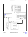
Overall system configuration
The overall system comprises a carrier system and a microscope system.
The basic configuration can be upgraded by various options to meet the
customer's specific requirements. All options available must be ordered
separately.
OPMI Pentero basic system
comprising:
–
OPMI Pentero with integrated binocular data injection system and integrated 3CCD MediLive video camera,
–
floor stand with touchscreen, integrated xenon illumination system
with 2x 300W lamps, autobalance and autodrape systems,
–
180° tiltable binocular tube with 10x push-in widefield eyepieces, spinal adapter for symmetric face-to-face configuration,
–
dust cover, 2 video connecting cables, CD-R and USB media for data
archiving.
Digital video recording *
Integrated digital video recording system with DVD archiving.
See page 244.
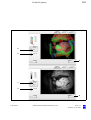
Integrated fluorescence module
–
INFRARED 800 (IR800) *** see page 261
–
FLOW 800 (processing mode for IR 800) *** see page 287
–
BLUE 400 (BL400) ***see page 339
Voice control - dictation - telephony **
Integrated system for voice control, telephony, dictation function
DICOM network interface **
This option permits data exchange with an RIS or PACS system (Radiological Information System or Patient Image Archiving System) via a hospital network system based on the DICOM standard.
G-30-1458-en
OPMI® Pentero® Software Release 2.20 / 2.21
Issue 11.1
Printed on 18. 02. 2009
42
Description
Stereo video system*
The stereo video option permits 3D viewing or recording of videos using
suitable external systems.
Neuromonitoring kit for OPMI Pentero
This accessory permits reliable operation in conjunction with neuromonitoring systems (reduced electromagnetic interference radiation).
HDTV merchandise*
Visualization of the microscope's field of view in maximum quality on a
monitor.
*
**
***
G-30-1458-en
Option
Option, under development (currently not yet available)
The system has been approved in the EU under directive 93/42/EEC.
However, according to national regulations, additional authorization may
be required in the country in which the system and application will be
used.
The fluorescence option is also available in other countries. Please contact your local Carl Zeiss representative for further information.
OPMI® Pentero® Software Release 2.20 / 2.21
Issue 11.1
Printed on 18. 02. 2009
43
Description
G-30-1458-en
OPMI® Pentero® Software Release 2.20 / 2.21
Issue 11.1
Printed on 18. 02. 2009
44
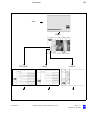
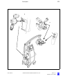
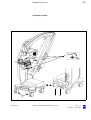
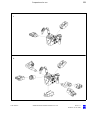
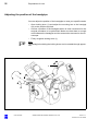
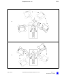
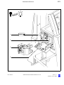
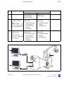
Description
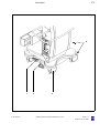
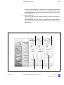
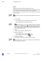
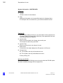
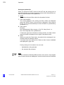
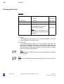
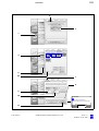
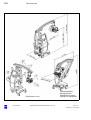
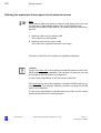
Configuration options
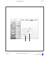
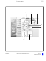
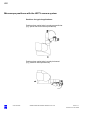
Warning!
Please note: The maximum load (accessory equipment) on the microscope body must not exceed 6 kg!
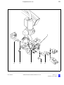
G-30-1458-en
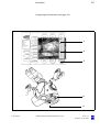
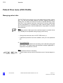
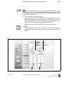
1
Surgical microscope with f=170 mm straight tube
2
Tiltable binocular tube, f=170 mm
3
Spine adapter
4
Tiltable binocular tube, f=170 mm, for face-to-face use
5
Stereo coobservation module with straight or tiltable binocular tube
6
Digital SLR camera with camera adapter
7
Zeiss MM6 micromanipulator
(or micromanipulators from other manufacturers)
8
Antenna (navigation system accessory)
When a navigation system is connected, the OPMI Pentero has to be
additionally equipped with an antenna supplied by the manufacturer of
the navigation system, and then calibrated.
OPMI® Pentero® Software Release 2.20 / 2.21
Issue 11.1
Printed on 18. 02. 2009
45
Description
1
4
6
2
8
3
5
7
G-30-1458-en
OPMI® Pentero® Software Release 2.20 / 2.21
Issue 11.1
Printed on 18. 02. 2009
46
Description
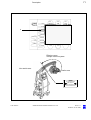
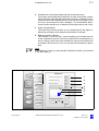
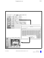
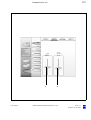
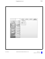
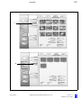
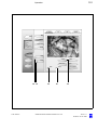
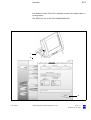
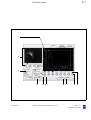
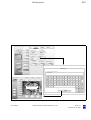
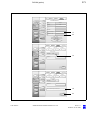
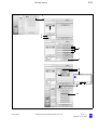
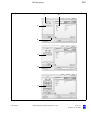
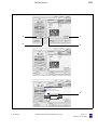
Central user interface (touchscreen)
The video-capable, graphic touchscreen is the user's central communication interface with the system, connected databases and internet connections. In the main menu, it always displays the image of the 3CCD video
camera integrated in the microscope body.
The touchscreen gives the user access to the settings of the microscope,
suspension system, light source and of the programmable parts of the
handgrips and foot control units. It is possible to store settings specific to
each user. A sufficient number of memory locations are available for different users.
A full-screen mode permits the touchscreen to be used as a video monitor.
Note:
The touchscreen has not been optimized for displaying video images. We
recommend a suitable, external video monitor for high-grade visualization
of the video images recorded with the integrated 3CCD MediLive camera.
The control panel can be rotated through approx. ± 90° and tilted through
approx. 20°, permitting easy viewing and operation by the user or other
persons.
All functions can be interactively controlled using menus. The display
shows the selected functions and settings.
The current date and time are displayed at the top left.
.
The user interface is largely self-explanatory:
•
Press the relevant button to select or activate a function.
•
Press and adjust a slider to change a parameter.
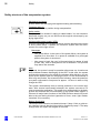
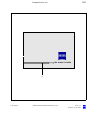
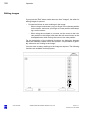
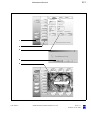
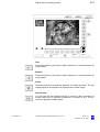
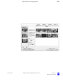
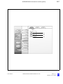
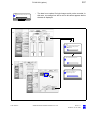
Selecting images from a thumbnail preview:
G-30-1458-en
•
Press the image required - the selected image will be displayed with a
blue frame.
•
To select the image for saving, press the Select button. The storage
symbol is displayed in the image.
You can undo the selection by pressing the selected image and the
Select button once again. The storage symbol disappears.
•
To delete the image, press the Delete button.
Before the image is deleted, a dialog is displayed, requesting you to
confirm the deletion.
OPMI® Pentero® Software Release 2.20 / 2.21
Issue 11.1
Printed on 18. 02. 2009
47
Description
Note:
Previously saved images are marked by a storage symbol.
•
BACK
NEXT
Press these buttons for browsing. The next or previous image will be
displayed.
These buttons are only active in selection or configuration menus if
several pages exist.
Note:
The graphic display is provided with a thin, pressure-sensitive plastic
cover. For this reason, tip the display with your finger only and do not use
pointed, hard objects which could damage the display.
Warning!
Do not use the stored images and videos for diagnostic purposes, as the
video cameras and the monitor have not been calibrated. The visualized
images may therefore include deviations in scale, color and shape.
The readings displayed are rounded values and are only provided for display and not for measuring purposes.
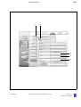
PHOTO
MENU
FOCUS
359 mm
ZOOM
LIGHT
5.9x
33%
FREEZE
30. 01. 0417:56
45%
User:
DRAPE
XXXXXXXX
Patient:
XXXXXXX
Recorder Capacity:
AUTOBALANCE
Int:.......% Ext:.........%
REC START
PAT-FILES
VOICECTRL
USER
CONFIG
DICTATION
TELEPHONE
FOCUS
FULL SCREEN
G-30-1458-en
359 mm
ZOOM
SPEED
OPMI® Pentero® Software Release 2.20 / 2.21
LIGHT
INTENSITY
Issue 11.1
Printed on 18. 02. 2009
48
Description
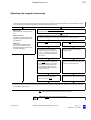
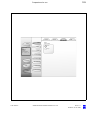
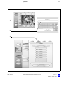
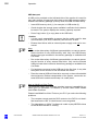
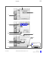
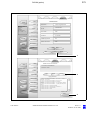
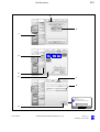
Menu overview
The menu is structured as follows:
MENU
The main menu is constantly displayed after the system has been started.
You can use it for triggering a still camera and video recording, for automatic balancing of the system, for activating the drape vacuum system
and for switching the illumination on and off. You can also activate the
voice control, dictation and telephone functions (option). The full-screen
mode permits you to view images or the live video signal in full display
size.
PAT-FILES
Use the Patient Files menu (page 174) to save, edit and manage patient
data, videos, images and audio data.
USER
The USER menu (page 116) permits you to save user-specific settings for
several different users. In addition, you can select several different languages for user guidance here.
CONFIG
The CONFIG menu (page 124) permits you to enter the settings for the
microscope and suspension system parameters.
G-30-1458-en
OPMI® Pentero® Software Release 2.20 / 2.21
Issue 11.1
Printed on 18. 02. 2009
49
Description
Start
MENU
XXXXXXX
PAT-FILES
G-30-1458-en
USER
OPMI® Pentero® Software Release 2.20 / 2.21
CONFIG
Issue 11.1
Printed on 18. 02. 2009
50
Description
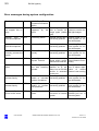
Main menu
PHOTO
Press the button to trigger image recording. The captured image is displayed for approx. 5 seconds in the full-screen mode on the touchscreen,
and is then automatically saved in the preconfigured image format in the
previously selected patient directory.
Press the "CLOSE" button to return to the main menu.
It is not possible to exit the main menu during image recording.
LIVE / FREEZE
When you press this button, a freeze image is created in the full-screen
mode. Press the button again to return to the standard live mode.
DRAPE
Press the DRAPE button to activate or deactivate the drape vacuum
system, see page 70.
AUTOBALANCE
For automatic balancing of the system. (See "Preparations for use / Balancing the system", page 110).
REC START / REC STOP (option)
For starting and ending a digital video recording. While video recording is
in progress, a "Rec" display with the recording length appears on the
monitor and in the data injection system.
VOICE CTRL (option, currently not yet available)
Various system functions can be activated by voice control.
DICTATION (option, currently not yet available)
This option permits the digital recording of an audio file (e.g. a comment
on the video)
TELEPHONE (option, currently not yet available)
This function permits you to use the system for phoning (integrated microphone and loudspeaker).
FULL SCREEN
You can switch the video image from the window mode to the full screen
mode.
Note:
– In the full screen view, in the PAT-FILES menu, two buttons ("Back"
and "Next") are displayed, permitting you to browse through several
images. Press the "CLOSE" button to return to the main menu.
–
G-30-1458-en
The values displayed by the system for zoom, focus and light are
rounded values; they are only intended for information, not for measurement purposes.
OPMI® Pentero® Software Release 2.20 / 2.21
Issue 11.1
Printed on 18. 02. 2009
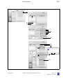
51
Description
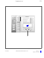
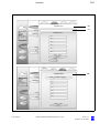
1
Activating the setting bar
2
Continuous adjustment of settings (e.g. zoom) using the slider.
PHOTO
MENU
FOCUS
ZOOM
LIGHT
359 mm
5.9x
33%
FREEZE
ZOOM
SPEED
30. 12. 0417:56
45%
User:
DRAPE
XXXXXXXX
Patient:
XXXXXXX
Recorder Capacity:
AUTOBALANCE
Int:.......% Ext:.........%
REC START
PAT-FILES
2
VOICECTRL
USER
CONFIG
DICTATION
TELEPHONE
FULL SCREEN
FOCUS
SPEED
ZOOM
SPEED
LIGHT
INTENSITY
1
G-30-1458-en
OPMI® Pentero® Software Release 2.20 / 2.21
Issue 11.1
Printed on 18. 02. 2009
52
Description
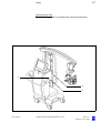
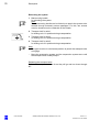
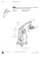
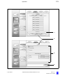
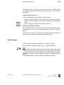
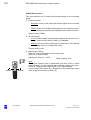
Controls and connections
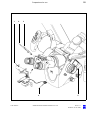
G-30-1458-en
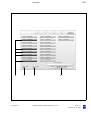
1
Microscope mount
2
Handgrips with programmable buttons
3
Left beamsplitter port
for documentation and coobservation devices (e.g. still camera or
coobservation tube).
4
Microphone
5
Locking screw for clickstop mechanism
After opening the locking screw, you can turn the tube (7, next page)
to the left or right to three clickstop positions in steps of 5°.
6
Handgrip locking mechanism
After opening the locking levers, you can adjust the ball-jointed handgrips as required.
OPMI® Pentero® Software Release 2.20 / 2.21
Issue 11.1
Printed on 18. 02. 2009
53
Description
1
G-30-1458-en
2
3
4
OPMI® Pentero® Software Release 2.20 / 2.21
5
2
6
Issue 11.1
Printed on 18. 02. 2009
54
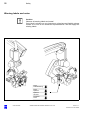
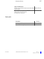
Description
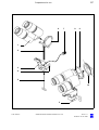
7
180° tiltable tube
with f=170 mm focal length and 10x eyepieces
8
Spine adapter (removable)
for improved operating convenience in spinal applications
9
Securing screw
for tube or spine adapter
10 Zoom adjusting knob (manual zooming)
11 Right beamsplitter port
for documentation and coobservation devices (e.g. still camera or
coobservation tube).
12 Adjusting knob for Varioskop (manual focusing)
13 Adjusting knob for illuminated field diameter (zoom illumination)
Warning!
Adjust the illuminated field diameter and illumination intensity to the
values required for the procedure! (See page 23)
14 Sliding mirror, manual setting (emergency function)
The sliding mirror has two positions:
Pos. 1:
The light is directed to the tube mount at the back.
Pos. 1
Pos. 2
Pos. 2:
The light is directed to the lateral image exit ports. If an external
camera is released and the sliding mirror is in Pos. 1, the mirror
switches to Pos. 2 during image capture.
Note:
The type of coobservation (lateral image exit ports: left/right, or opposite image exit ports: face to face) can be configured at the touchscreen, see page 130.
The sliding mirror is electronically positioned accordingly.
15 180° tiltable coobservation tube
with f=170 mm focal length and 10x eyepieces
G-30-1458-en
OPMI® Pentero® Software Release 2.20 / 2.21
Issue 11.1
Printed on 18. 02. 2009
55
Description
15
14
7
G-30-1458-en
8
9
10 11 12
13
OPMI® Pentero® Software Release 2.20 / 2.21
Issue 11.1
Printed on 18. 02. 2009
56
Description
16 Dovetail for connecting a micromanipulator
A Zeiss MM6 micromanipulator can be attached to the surgical microscope via the dovetail mount on the bottom of the microscope to
permit the use of a laser. Micromanipulators from other manufacturers
can be connected, but not electronically controlled.
Note:
For the OPMI Pentero, only CZ MM6 micromanipulators carrying the
label "Adjusted for OPMI Neuro" may be used.
Adjusting the surgical microscope and laser micromanipulator to
the same focal plane
The OPMI Pentero is equipped with a motorized Varioskop zoom system
which is operated via the focus rocker switches of the handgrips (Pos. 4/
5, see page 64) or the focus buttons on the foot control panel (Pos. 5/6,
see page 138).
The Varioskop is used for the motorized setting of the working distance
(coarse focus) and the motorized adjustment of image definition (fine
focus). The focus rocker switches allow you to continuously adjust the
working distance between 200 mm and 500 mm.
•
Set the working distance (coarse focus) to the focus value of the laser
micromanipulator. The central user interface (touchscreen) always
displays the focus value currently set.
•
Use the previously described, recommended procedure to check that
the focal planes coincide.
•
If necessary, correct the focus by appropriate minor adjustment (fine
focus).
The Focus Stop function (Pos. 2 page 124) permits you to deactivate the
electrical drive of the focusing system. The focus rocker switches are disabled. This prevents the focal plane setting from being inadvertently
changed by motorized movement. If Focus Stop has been activated, no
autofocus setting is performed when the brakes are operated, even if the
autofocus has been switched on.
G-30-1458-en
OPMI® Pentero® Software Release 2.20 / 2.21
Issue 11.1
Printed on 18. 02. 2009
57
Description
16
G-30-1458-en
OPMI® Pentero® Software Release 2.20 / 2.21
Issue 11.1
Printed on 18. 02. 2009
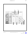
58
Description
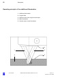
17 Lever for additional illumination
This lever permits you to switch the additional illumination on and off.
See "Operating principle of the auxiliary illumination" on page 68.
Note:
The additional illumination cannot be used when the MM6 micromanipulator has been connected.
18 Mouth switch socket
You can use the mouth switch (option) to release or lock the magnetic
brakes for the three main axes of the suspension system. The mouth
switch has the same function as the SB brake control button on the
handgrip.
For mounting the mouth switch, see page 94.
19 Camera release socket
for an external still camera
20 Socket
for connecting an optional antenna module (navigation).
G-30-1458-en
OPMI® Pentero® Software Release 2.20 / 2.21
Issue 11.1
Printed on 18. 02. 2009
59
Description
17
G-30-1458-en
OPMI® Pentero® Software Release 2.20 / 2.21
18
19
20
Issue 11.1
Printed on 18. 02. 2009
60
Description
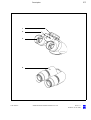
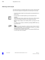
Binocular tubes and eyepieces
Depending on the application involved, you can equip the surgical microscope either with one 180° tiltable tube, two 180° tiltable tubes (face-toface) or with one straight tube only.
180° tiltable tube
1
PD adjustment knob
The correct position has been reached when the two eyepiece images
merge into one.
2
180° tiltable binocular tube, f = 170 mm
3
Eyepiece mount
Straight tube
4
G-30-1458-en
Straight tube, f = 170 mm
OPMI® Pentero® Software Release 2.20 / 2.21
Issue 11.1
Printed on 18. 02. 2009
61
Description
1
2
3
4
G-30-1458-en
OPMI® Pentero® Software Release 2.20 / 2.21
Issue 11.1
Printed on 18. 02. 2009
62
Description
Widefield eyepieces with magnetic coupling
Note:
When the eyepiece has been removed from the tube, please remember
that it is equipped with a magnetic coupling. Attached eyepieces feature
a very minor magnetic field, i.e. the usual regulations for the handling of
magnets must only be observed with non-attached eyepieces.
G-30-1458-en
•
Do not place the eyepiece near instruments which may be magnetic.
•
Do not place the eyepiece on sensitive electronic instruments such as
infusion pumps, heart pacemakers, measuring instruments or magnetic data carriers such as disks, audio/video tapes or credit cards.
•
Always store the eyepiece in its original packaging, when not using it.
1
Eyecup
Always adjust the eyecups in such a way that the entire field of view
can be seen.
–
Viewing with eyeglass- Screw in the eyecups all the way.
es:
–
Viewing without
glasses:
eye- Adapt the eyecups to the viewer's field
of view by screwing them outward.
The three white marking rings facilitate the adjustment.
2
Diopter setting ring
The eyepieces enable you to set your prescription between -8 D and
+5 D. Eyeglass wearers using their glasses during work should set the
diopter setting ring to 0. Turn the ring until the optimum setting has
been achieved. An integrated brake holds the setting ring in the position set.
3
Diopter scale
For reading off the prescription set.
OPMI® Pentero® Software Release 2.20 / 2.21
Issue 11.1
Printed on 18. 02. 2009
63
Description
1
2
3
G-30-1458-en
OPMI® Pentero® Software Release 2.20 / 2.21
Issue 11.1
Printed on 18. 02. 2009
64
Description
Handgrips
G-30-1458-en
1
Programmable button A
(factory setting: trigger photo)
2
Programmable button B
(factory setting: autofocus)
3
Joystick
In the basic setting, both joysticks can be used for motorized fine
movement in the XY directions.
If the MultiVision function is active, the joystick of the right handgrip is
used to control a mouse cursor for the functions of a connected navigation system (depending on the system used) or for menu control of
the displayed touchscreen.
Note:
Major system errors are displayed in the microscope's integrated data
injection system. You can delete these messages by acknowledgement using the joystick of the right handgrip (pushbutton) or the touchscreen.
4
Focus + / focus - rocker switch (factory setting)
for continuous focusing within the working distance of 200 mm to
500 mm. The current value is displayed on the screen.
5
Zoom + / zoom - rocker switch (factory setting)
for magnification setting. The current value is displayed on the screen.
Note:
The zoom and focus functions of the two rocker switches (4 and 5)
can be interchanged. Call up the CONFIG menu / STAND / HANDGRIPS and briefly press button C. The displays and functions are interchanged
6
Programmable button D
(factory setting: reduce illumination intensity)
7
Programmable button E
(factory setting: increase illumination intensity)
8
Brake release button (AB)
Brake release button for all suspension system and microscope axes.
For as long as you press this button, all magnetic brakes are released
("All Brakes") and the system can be moved in all directions. When
you let go of the button, the magnetic brakes simultaneously lock all
axes in position.
9
Brake release button (SB)
OPMI® Pentero® Software Release 2.20 / 2.21
Issue 11.1
Printed on 18. 02. 2009
65
Description
Brake release button for the microscope axes or suspension system
axes (factory setting). For as long as you press this button, only the
magnetic brakes of the suspension system or microscope axes are released ("Selected Brakes"), and the suspension system or microscope can be moved in all directions. When you let go of the button,
the magnetic brakes simultaneously lock these axes in position.
The configuring of the handgrips is described on page 106.
1
2
3
4
5
6
7
8
G-30-1458-en
OPMI® Pentero® Software Release 2.20 / 2.21
9
Issue 11.1
Printed on 18. 02. 2009
66
Description
Superlux 330 illumination system
The illumination system has been completely integrated in the system.
The light source generates light whose spectrum resembles that of natural daylight. Regardless of the brightness setting, the color temperature
of the light always remains the same.
The illumination system contains two xenon lamps. The second lamp is
used as a backup lamp which can be swung into the illumination beam
path via a quick-action changer when the first lamp fails. This change
takes no longer than a few seconds (lamp change see page 222).
Warning!
Never use xenon illumination for ophthalmic procedures.
Make sure that no xenon light enters the patient's eyes.
Make sure that no tissue damage is caused by excessive illumination intensity (see page 20).
Caution:
Do not cover the ventilation grid on the stand console. This can lead to
overheating of the lamp modules and to lamp failure.
1
Switching the illumination on and off
In the main menu on the touchscreen or in the Config menu (Preparations for use / Light, see page 132); (factory setting: light on)
2
Adjusting the illumination intensity
Continuously variable from minimum to maximum brightness in a
range from 5% to 100%.
You can adjust the illumination intensity using the programmable buttons on the handgrips or foot control panel, or via the main menu on
the touchscreen.
Warning!
The illumination intensity has been preconfigured in such a way that a
warning is displayed on the touchscreen when the threshold value of
25% is exceeded, informing the user of possible tissue damage.
3
Activating the setting bar
4 Adjusting the illuminated field diameter
Warning!
Adjust the illuminated field diameter and illumination intensity to the
values required for the procedure! (See page 23)
5
G-30-1458-en
Manually switching the additional illumination on and off
OPMI® Pentero® Software Release 2.20 / 2.21
Issue 11.1
Printed on 18. 02. 2009
67
Description
Configuring the illumination, see page 132.
MENU
30. 01. 0417:56
PHOTO
FOCUS
ZOOM
359 mm
5.9x
LIGHT
ON
LIGHT
ON/OFF
FREEZE
1
User:
XXXXXXXX
DRAPE
Patient:
33%
XXXXXXX
Recorder Capacity:
AUTOBALANCE
Int:.......% Ext:.........%
REC START
2
PAT-FILES
VOICECTRL
USER
DICTATION
TELEPHONE
CONFIG
FULL SCREEN
FOCUS
SPEED
ZOOM
SPEED
LIGHT
INTENSITY
3
4
5
G-30-1458-en
OPMI® Pentero® Software Release 2.20 / 2.21
Issue 11.1
Printed on 18. 02. 2009
68
Description
Operating principle of the additional illumination
1
Additional illumination
2
Surgical field
3
Objective lens of the surgical microscope
4
Main illumination
5
Shadow area of main illumination
3
G-30-1458-en
1
4
2
5
OPMI® Pentero® Software Release 2.20 / 2.21
Issue 11.1
Printed on 18. 02. 2009
69
Description
Autofocus (focusing aid)
Operating principle
On activation of the function, two parallel, visible laser beams enter the
Varioskop and intersect in the focal plane. The Varioskop focusing system
is adjusted until the laser beams meet in one point, i.e. until the object
plane and the focal plane coincide. The system distinguishes between the
right and left laser beams, permitting targeted movement in a defined direction.
When the system is focused in very narrow channels or on glossy,
strongly reflecting surfaces, it may happen that one of the two laser
beams does not strike the target plane. Laser measurement becomes impossible in this case. The system therefore performs automatic focusing
using video contrast measurement.
Activating the autofocus
You can start the autofocus by:
G-30-1458-en
–
pressing an appropriately configured handgrip button (A, B, D,E)
–
pressing an appropriately configured foot control button (A, B, C, D)
–
linking it with the brake function, i.e. the autofocus is automatically activated after the magnetic brakes are locked.
–
optional voice control
–
For configuring the autofocus function, see page 108 and page 124.
OPMI® Pentero® Software Release 2.20 / 2.21
Issue 11.1
Printed on 18. 02. 2009
70
Description
Drape vacuum system
To facilitate the draping of the system and intraoperative processes for
the OR staff, the system features an integrated drape vacuum system
which extracts the air from the drape at the suspension arm and surgical
microscope.
•
The drape vacuum pump is activated by pressing DRAPE button (1)
in the main menu.
Note:
The vacuum system operates at maximum power during the first 2 minutes approximately. Then it automatically switches to a defined maintaining power to keep up the vacuum.
•
The drape vacuum pump is switched off by pressing DRAPE button
(1) in the main menu once again.
Attaching sterile drapes, see page 100.
G-30-1458-en
OPMI® Pentero® Software Release 2.20 / 2.21
Issue 11.1
Printed on 18. 02. 2009
71
Description
MENU
PHOTO
FOCUS
ZOOM
LIGHT
359 mm
5.9x
33%
FREEZE
1
DRAPE
AUTOBALANCE
REC START
PAT-FILES
VOICECTRL
USER
DICTATION
TELEPHONE
CONFIG
FULL SCREEN
FOCUS
SPEED
ZOOM
SPEED
LIGHT
INTENSITY
Effective range
of drape vacuum system
Non-sterile area
Sterile area
DRAPE
Hier luftdicht abschließen
Make airtight here
Fermer hermétiquement ici
Cerrar hermélicamente aqui
G-30-1458-en
OPMI® Pentero® Software Release 2.20 / 2.21
Issue 11.1
Printed on 18. 02. 2009
72
Description
Stand base /FlexiTrack™ system
The base of the floor stand permits free positioning and movement of the
system in all directions. The FlexiTrack system enables steered straightahead movement in corridors and through doorways, and easy, flexible
positioning of the system in the OR. It is also easy to drive over thresholds
or small obstacles (e.g. elevator doors).
If none of the pedals described below has been pressed, the stand can
be moved in any direction. This setting is suited for positioning the floor
stand in its location of use. It should, however, not be used to relocate the
system over long distances.
1
Locks
Press down the pedal all the way to lock the stand in position.
Press pedal for straight-ahead movement (2) to release the locking
pedal. You can now move the stand as required.
2
Pedal for straight-ahead movement
Press this pedal until it snaps in to set the two front casters (4) for
straight-ahead travel. Slightly jiggle the suspension system until the
two front casters click in straight-ahead travel position. The other
casters remain steerable.
Choose this possibility for steering the stand over long distances and
for movement in a straight-ahead direction.
STOP
When you press pedal (1), all four casters will be steerable again.
3
G-30-1458-en
Steerable double caster with cable deflector
OPMI® Pentero® Software Release 2.20 / 2.21
Issue 11.1
Printed on 18. 02. 2009
73
Description
4
1
G-30-1458-en
2
3
OPMI® Pentero® Software Release 2.20 / 2.21
Issue 11.1
Printed on 18. 02. 2009
74
Description
Relocating the system
1
Maneuvering handle
for relocating the system.
Note:
The maneuvering handle can be folded up to permit the system to be
steered through extremely narrow passages. For this, two screws
must be loosened on the underside of the handle.
2
Transport lock for axis 1
for locking axis 1 in position during transportation.
3
Transport lock for axis 3
for locking axis 3 in position during transportation.
4
Transport lock for axis 2
for locking axis 2 in position during transportation.
Note:
– The grips must be in a horizontal position to permit the transport locks
to engage.
–
Move the suspension system and the suspension system arms until
the transport locks audibly snap in.
Releasing the transport locks
Pull out the transport locks as far as they will go and turn them through
90°.
G-30-1458-en
OPMI® Pentero® Software Release 2.20 / 2.21
Issue 11.1
Printed on 18. 02. 2009
75
Description
Axis 2
1
OP
MI
Pe
nte
ro
Axis 3
2
4
3
Axis 1
G-30-1458-en
OPMI® Pentero® Software Release 2.20 / 2.21
Issue 11.1
Printed on 18. 02. 2009
76
Description
Connector panel
1
Power switch
When the system is on, the green indicator light in the switch is lit.
2
Power inlet, 115/230 V
Only connect the system to a wall outlet which is provided with a properly connected protective ground conductor.
Caution:
Please observe the maximum current consumption of power outlet
socket (3). Only connect medical devices approved by us to this outlet (3).
When using other instruments, make sure that safety is guaranteed regarding admissible ground leakage currents. The admissible limit value of
the ground leakage current present in the suspension system's power
cord is 500 µA in compliance with EN60601-1/IEC 601-1. CSA NRTL certification only allows a maximum ground leakage current of 300 µA.
3
115/230 V power outlet
for medical devices with a current consumption of max. 2A.
4
Indicator window for rated voltage
The voltage shown here must correspond to the rated voltage provided on the site of installation.
5
Potential equalization
for connection of the system to the potential equalization system in the
OR.
6
Cover for standard operation / emergency mode selector switch
In the emergency setting, only the illumination system is operational.
All other functions are inactive.
7
Connector panel with video ports, left (mono):
8
Video signal output port, BNC (VBS)
9
Video-DV out
10 Progressive scan (VGA) or RGB output port
(See Video menu/“Selecting the video format for an external video
port“)
11 Video signal output port for an external monitor (Y/C)
G-30-1458-en
OPMI® Pentero® Software Release 2.20 / 2.21
Issue 11.1
Printed on 18. 02. 2009
77
Description
7
8
6
9
5
10
11
4
3
2
1
G-30-1458-en
OPMI® Pentero® Software Release 2.20 / 2.21
Issue 11.1
Printed on 18. 02. 2009
78
Description
12 External automatic circuit breakers
If one of the automatic circuit breakers is activated, try to reactivate the
function by pressing the circuit breaker button. Should the automatic
circuit breaker be activated again, call our service dept.
13 Video in Y/C
e.g. for an endoscope camera
14 AUX socket
for controlling an external unit, e.g. a video recorder.
15 Socket
for a foot rocker switch (included in delivery package)
16 Connector for switching component
Possibility of connecting a foot control panel, footswitch or an operating chair with appropriate footswitch.
17 Modem connection
18 Ethernet connection (LAN)
19 Connector for cable
Connecting a microscope navigation system
20 Connector panel with video ports, right (stereo) (option):
21 Video signal output port, BNC (VBS) (option)
22 Video-DV out (option)
23 Progressive scan (VGA) or RGB output port
(See Video menu/“Selecting the video format for an external video
port“)
24 Video signal output for an external monitor (Y/C) (option)
Note:
– The stereo video option (items 20-24) enables you to view or record
video in 3D using suitable external systems (See page 18).
–
G-30-1458-en
In the stereo mode, it is important to connect channels L and R of the
3D system to ports of the same video standard (BNC/VBS or Y/C).
OPMI® Pentero® Software Release 2.20 / 2.21
Issue 11.1
Printed on 18. 02. 2009
79
Description
12 13 14 15
16
17 18
19
20
21
22
23
24
G-30-1458-en
OPMI® Pentero® Software Release 2.20 / 2.21
Issue 11.1
Printed on 18. 02. 2009
80
Description
Connecting navigation systems
The OPMI Pentero is fully prepared for the connection of navigation systems. The link-up using the navigation interface creates a medical system
for which the system supplier (manufacturer of the navigation system)
must meet the stipulated requirements (approval, qualifications, etc.). All
accompanying papers required will be supplied by the manufacturer of the
navigation system.
The navigation interface to the OPMI Pentero was developed in cooperation with Carl Zeiss in compliance with the guidelines of the communication protocol for the OPMI Pentero navigation interface.
Additional information is available from our service department or from
authorized representatives.
The use of the OPMI Pentero with a connected navigation system requires calibration of the microscope using a technique to be made available by the manufacturer of the connected navigation system. This allows
the OPMI Pentero combined with the navigation system to be used like an
optical pointer with a variable length (corresponds to the working distance).
–
The OPMI Pentero can manage various connected navigation systems and the associated data injection parameters (currently not yet
available, systems must be appropriately matched).
–
For safety reasons, the OPMI Pentero navigation interface is not enabled unless a connected system authenticates itself.
–
Before every surgery using a connected and authenticated navigation
system, the function and accuracy of this navigation system must be
verified, including visualization in the data injection mode (e.g. focusing on a measuring point or comparison of the focus with the instrument to be navigated). Please also observe the information contained
in the respective user's manual for the navigation system used.
Caution:
For safety and accuracy reasons, the integrated, rotatable tube dovetail
mounts must not be used for the operation of OPMI Pentero with a connected navigation system. They must be carefully locked in the central position (tighten the knurled screw to prevent rotation).
•
G-30-1458-en
Please follow the instructions given in the user manual for the connected navigation system regarding the configuration of the surgical
microscope for use as a navigation tool. This manual is provided by
the manufacturer of the navigation system.
OPMI® Pentero® Software Release 2.20 / 2.21
Issue 11.1
Printed on 18. 02. 2009
81
Description
Connection and operation of navigation systems
Only systems from authorized manufacturers may be connected and
used on the navigation interface of OPMI Pentero. Authorized manufacturers are companies or institutions with which Carl Zeiss Surgical has
concluded an Open Interface Contract and for which the use of the integrated navigation interface with data injection system has been licensed.
Please observe the user manual for the connected system.
G-30-1458-en
OPMI® Pentero® Software Release 2.20 / 2.21
Issue 11.1
Printed on 18. 02. 2009
82
Description
Navigation interfaces
G-30-1458-en
1
Joystick
The joystick button on the right handgrip can be used to control software functions of the connected navigation system, if this is supported
by the navigation system.
2
Connector (example)
for an external microscope navigation system.
3
Interface on the surgical microscope
for connecting an optional antenna module.
OPMI® Pentero® Software Release 2.20 / 2.21
Issue 11.1
Printed on 18. 02. 2009
83
Description
2
3
1
G-30-1458-en
OPMI® Pentero® Software Release 2.20 / 2.21
Issue 11.1
Printed on 18. 02. 2009
84
Description
G-30-1458-en
OPMI® Pentero® Software Release 2.20 / 2.21
Issue 11.1
Printed on 18. 02. 2009
85
Preparations for use
Preparations for use
G-30-1458-en
Relocating the unit
86
Assembling the system
88
Configurations
88
Mounting the tube and the eyepieces
90
Attaching documentation / coobservation equipment
92
Mounting the mouth switch (option)
94
Adjusting the position of the handgrips
98
Attaching sterile drapes
100
Positioning the system at the operating table
102
Starting the system
104
Configuring the handgrips
106
Balancing the system
110
Adjusting the surgical microscope
115
USER menu / login
116
Activating IT system rights and data protection
120
Configuration menu (CONFIG)
124
OPMI® Pentero® Software Release 2.20 / 2.21
Issue 11.1
Printed on 18. 02. 2009
86
Preparations for use
Relocating the unit
Note:
– As the stand can be easily maneuvered, there is a tendency to underestimate its weight. Therefore, move the stand slowly and carefully!
–
Pedal for straight-ahead movement (2):
Press this pedal until it snaps in to set the two front casters (4) for
straight-ahead travel. The other casters remain steerable.
Choose this possibility for steering the stand over long distances and
for movement in a straight-ahead direction.
When you slightly press pedal (1), all four casters will be steerable
again.
This setting is ideally suited for positioning the stand in its location of
use. It is, however, not suited for relocating the stand over long distances.
Please observe the following points when relocating the stand:
STOP
•
Bring the stand into its transport position. (See illustration). Lock the
stand in the transport position by allowing transport locks (3) to engage.
•
Unplug the power cord from the wall outlet.
•
Hang the foot control panel on the hook provided on the handle.
•
Hang the power cord on the hooks provided on the handle.
•
Release locking tab (1) by pressing pedal (2).
•
Be careful of heights when passing through doorways.
•
Avoid collisions of any kind.
•
Do not go over steps and edges: the column might topple!
•
Be extremely careful when moving over slopes.
•
Do not park the stand on slopes.
•
Step on pedal (1) on the base to secure the stand in position. Make
sure that the stand is stable and in a horizontal position, and cannot
roll away.
Note:
Over longer distances (e.g. removal, return for repair, etc), the instrument
may only be transported in the original packaging or in special return
packaging. Please contact your dealer or the Carl Zeiss service team.
G-30-1458-en
OPMI® Pentero® Software Release 2.20 / 2.21
Issue 11.1
Printed on 18. 02. 2009
87
Preparations for use
Transport position:
3
4
G-30-1458-en
1
OPMI® Pentero® Software Release 2.20 / 2.21
2
Issue 11.1
Printed on 18. 02. 2009
88
Preparations for use
Assembling the system
Configurations
The OPMI Pentero has been designed for different applications in microsurgery. The stand has been designed for optimum maneuverability. For
this reason, a minimum and a maximum configuration are recommended
to ensure the safe use of the system.
Minimum configuration (1) comprises e.g. two tiltable tubes with eyepieces or a straight tube with eyepieces and a stereo coobservation
module with tube and eyepieces.
The maximum admissible load (configuration options (2)) on the microscope body must not exceed 6 kg! (For weight data, see Accessories
page 228). This configuration comprises, for example, a still camera, a
face-to-face adapter with a second tiltable tube, a stereo coobservation
module with a tiltable tube, a micromanipulator, etc.
Assemble the components you want to use as shown in the illustration on
the opposite page and check that they are exactly positioned and firmly
mounted (knurled screws have been tightened).
Caution:
Check that the handgrips and accessories (coobservation or documentation equipment) have been correctly mounted, that they can be moved
without restriction across the full swivel range and that they cannot collide
with any other units.
Warning!
If the weight of the configuration used is higher/lower than that of the recommended configuration, the mobility or balance of the system may be
impaired.
G-30-1458-en
1
Minimum configuration
2
Configuration options
The maximum load on the microscope must not exceed 6 kg!
OPMI® Pentero® Software Release 2.20 / 2.21
Issue 11.1
Printed on 18. 02. 2009
89
Preparations for use
1
2
G-30-1458-en
OPMI® Pentero® Software Release 2.20 / 2.21
Issue 11.1
Printed on 18. 02. 2009
90
Preparations for use
Mounting the tube and the eyepieces
Warning!
Change the modules and accessories before surgery and without the patient!
Caution:
• The mounting and removal of modules and accessories leads to a
shift in the center of gravity in the microscope and suspension system
axes. This could lead to inadvertent tilting of the microscope. To avoid
this, balance the system using the autobalance function, see page
110.
•
Loosen securing screw (9) by a few turns.
•
Remove cover (4) and store it in a safe place.
You have the possibility of mounting tiltable binocular tube (2) or straight
tube (5) directly on the microscope body. For spinal applications, we recommend that you first mount spine adapter (3) on the microscope body,
followed by binocular tube (2).
•
Attach spine adapter (3) to the microscope body and firmly tighten securing screw (9).
•
Attach binocular tube (2) to spine adapter (3) and firmly tighten securing screw (8).
•
Insert widefield eyepieces (1) as far as they will go in the mounts provided on the binocular tube. The magnetic coupling reliably secures
them in position.
•
Attach binocular coobservation tube (6) to the microscope body and
firmly tighten securing screw (10).
•
Insert widefield eyepieces (7) as far as they will go in the mounts provided on the binocular tube. The magnetic coupling reliably secures
them in position.
Note:
If you wish to use documentation equipment, we can supply an eyepiece
with a reticle to aid focusing. The retrofitting of a reticle to an eyepiece can
only be performed in the factory or by our service staff. Always install the
eyepiece with the reticle on the same side of the binocular tube where the
documentation equipment is located.
G-30-1458-en
OPMI® Pentero® Software Release 2.20 / 2.21
Issue 11.1
Printed on 18. 02. 2009
91
Preparations for use
Caution:
Before starting up the system, remove protective cover (11) used for
transportation from the objective lens.
If the system is operated with protective cover (11) in place, the heat produced by the activated illumination system may cause the cover to melt,
leading to irreparable damage to the optical components!
Warning!
• Before every use and after re-equipping the instrument, make sure
that the modules are securely locked in position.
1
2
•
Make sure that securing screws (8) and (9) have been firmly tightened!
•
Always re-balance the surgical microscope after re-equipping the system.
3
8
G-30-1458-en
4
2
5
9
OPMI® Pentero® Software Release 2.20 / 2.21
11
6
7
10
Issue 11.1
Printed on 18. 02. 2009
92
Preparations for use
Attaching documentation / coobservation equipment
The camera adapter and coobservation module shown in the illustration
are examples of further accessories that can be mounted on the lateral
image exit ports. The method described below can also be used for other
accessories. The operating principle of the accessories is described in the
relevant user manuals.
•
Loosen knurled ring (1).
Note:
An arrow with the labeling "open" is located on the shaft next to
knurled ring (1).
•
Remove dust cover (2) and store it in a safe place.
•
Insert accessory module (3) in the opening of the image exit port. The
opening of the image exit port is fitted with guide projections. The accessory module (3) has the corresponding grooves. Carefully turn the
accessory module until the guide projections fit into the grooves, and
slide the accessory module in the opening as far as it will go.
•
Screw knurled ring (1) onto accessory module (3).
•
Firmly tighten knurled ring (1).
•
The type of coobservation (lateral image exit ports: left/right, or opposite image exit ports: face to face) can be configured at the touchscreen, see page 130.
The sliding mirror has two positions:
Left/right:
The light is directed to the lateral image exit ports. If an external
camera is released and the sliding mirror is in the face-to-face position, the mirror switches to the left/right position during image capture.
Face to face:
The light is directed to the tube mount at the back.
Note:
The position of the sliding mirror can also be switched manually using
knob (4).
G-30-1458-en
OPMI® Pentero® Software Release 2.20 / 2.21
Issue 11.1
Printed on 18. 02. 2009
93
Preparations for use
4
3
G-30-1458-en
2
1
2
OPMI® Pentero® Software Release 2.20 / 2.21
3
Issue 11.1
Printed on 18. 02. 2009
94
Preparations for use
Mounting the mouth switch (option)
Note:
For a detailed description, please see the user manual for the mouth
switch.
Mounting the mouth switch on the 180° tiltable tube
•
Remove three protective caps (2).
•
Secure mouth switch holder (1) using three screws (3) included in the
delivery package.
•
Tighten the screws using a 4 mm Allen key.
•
Connect contact plug (4) to mouth switch socket (5) on the surgical microscope.
•
Set the height, tilt and distance of the mouth switch via the relevant
locking screws and properly tighten these screws.
•
Make sure that the surgical microscope and suspension system are
properly balanced.
Autobalance - Fine adjustment for mouth switch, see page 112.
For operation of the mouth switch, see page 168.
G-30-1458-en
OPMI® Pentero® Software Release 2.20 / 2.21
Issue 11.1
Printed on 18. 02. 2009
95
Preparations for use
1
2
3
4
G-30-1458-en
OPMI® Pentero® Software Release 2.20 / 2.21
5
Issue 11.1
Printed on 18. 02. 2009
96
Preparations for use
Mounting the mouth switch on the straight tube
•
Remove locking screw (5) from toothed shaft (2).
•
Loosen locking screw (4) by a few turns.
•
Remove the mouth switch from the toothed shaft of the tiltable tube
mount (delivery status).
•
Align mouth switch (3) and push it onto toothed shaft (2).
•
Lock mouth switch (3) in position using locking screw (4).
•
Reinsert locking screw (5) in toothed shaft (2) and lock it.
•
Slide retaining ring (6) onto the front flange of the straight tube.
•
Make sure that the two recesses (8 and 9) coincide.
•
Attach the straight tube with the complete mouth switch to the microscope body and firmly tighten securing screw (10).
Autobalance - Fine adjustment for mouth switch, see page 112.
For operation of the mouth switch, see page 168.
G-30-1458-en
OPMI® Pentero® Software Release 2.20 / 2.21
Issue 11.1
Printed on 18. 02. 2009
97
Preparations for use
6
7
8
9
1
2
3
4
5
10
5
G-30-1458-en
OPMI® Pentero® Software Release 2.20 / 2.21
Issue 11.1
Printed on 18. 02. 2009
98
Preparations for use
Adjusting the position of the handgrips
You can adjust the position of the handgrips to meet your specific needs.
•
Open locking lever (1) and adjust the mounting bar or the handgrip
only to the position required.
•
Choose a position of the handgrips which is most convenient for the
surgical procedure to be performed. Make sure that there is enough
room between the handgrips and the accessories mounted on the microscope.
•
Firmly re-tighten locking lever (1).
Note:
The handgrips including the locking levers can be rotated through approx.
180°.
1
1
G-30-1458-en
OPMI® Pentero® Software Release 2.20 / 2.21
Issue 11.1
Printed on 18. 02. 2009
99
Preparations for use
G-30-1458-en
OPMI® Pentero® Software Release 2.20 / 2.21
Issue 11.1
Printed on 18. 02. 2009
100
Preparations for use
Attaching sterile drapes
The system features an integrated drape vacuum system which extracts
the air from the drape at the suspension arm and surgical microscope.
•
Unpack the drape and pull it over the surgical microscope and the suspension arm.
•
Pull the drape over marked position (2) of the suspension arm.
Caution:
When attaching the drape, please ensure that there is sufficient space
for the tilt and rotation movement of the surgical microscope.
•
Make the drape airtight at the marked position (2) using one of the
straps.
•
The drape vacuum pump is activated by pressing DRAPE button (1)
in the main menu.
Note:
The vacuum system operates at maximum power during the first 2
minutes approximately. Then it automatically switches to a defined
maintaining power to keep up the vacuum.
•
G-30-1458-en
The drape vacuum pump is switched off by pressing DRAPE button
(1) in the main menu once again.
OPMI® Pentero® Software Release 2.20 / 2.21
Issue 11.1
Printed on 18. 02. 2009
101
Preparations for use
MENU
PHOTO
FOCUS
ZOOM
LIGHT
359 mm
5.9x
33%
FREEZE
1
DRAPE
AUTOBALANCE
REC START
PAT-FILES
VOICECTRL
USER
DICTATION
TELEPHONE
CONFIG
FULL SCREEN
FOCUS
SPEED
ZOOM
SPEED
LIGHT
INTENSITY
Effective range
of drape vacuum system
2
Sterile area
Non-sterile area
DRAPE
Hier luftdicht abschließen
Make airtight here
Fermer hermétiquement ici
Cerrar hermélicamente aqui
G-30-1458-en
OPMI® Pentero® Software Release 2.20 / 2.21
Issue 11.1
Printed on 18. 02. 2009
102
Preparations for use
Positioning the system at the operating table
The stand is provided with a handle which allows the reliable and easy
guidance of the system during relocation. Please only use this handle for
this purpose.
The stand base is equipped with the new FlexiTrak technology which
makes it considerably easier for you to move and position the system in
the OR. Two additional pedals on the base allow you to conveniently select the required condition of the stand:
1
2
–
None of the pedals has been pressed:
Exact and sensitive positioning in the OR and at the operating table in
all directions with a minimum of effort.
–
Right-hand pedal (2) is pressed down hard until it snaps in:
Reliable and precise straight-ahead movement, also over low thresholds (elevator). Press this pedal until it snaps in to set the two front
casters for straight-ahead travel. The other casters remain steerable.
When you slightly press pedal (1), all four casters will be steerable
again.
–
Pressing left-hand pedal (1) to the stop will lock the stand base in position, preventing it from inadvertently rolling away. After the system
has been finally positioned at the operating table, you should step on
this pedal.
3
4
Possible positions for cranial procedures
Possible positions for face-to-face procedures (spine)
5
6
Surgeon
Assistant
Note:
The system allows overhead positioning and can therefore be placed in
any position behind the surgeon or assistant.
G-30-1458-en
OPMI® Pentero® Software Release 2.20 / 2.21
Issue 11.1
Printed on 18. 02. 2009
103
Preparations for use
5
3
6
5
6
4
G-30-1458-en
OPMI® Pentero® Software Release 2.20 / 2.21
Issue 11.1
Printed on 18. 02. 2009
104
Preparations for use
Starting the system
Note:
In general, the instrument is ready for operation after startup. A continuous beep indicates extreme discharging of the USP. In this case, the
system should not be powered up for at least five minutes. After this time,
you can power up the system again for charging the UPS. For the initial
startup or after long rest periods, we recommend the following: leave the
powered-up system connected to line power for approx. 12 hours in order
to fully charge the UPS.
After power-up of the system, the user interface is initialized. The
progress of initialization is indicated by horizontal bar (1). During this
process, the system performs a self-test. After the self-test, the system is
ready (abbr. 90 sec.) for use and switches to the main menu. In the event
of an error, the user is informed both visually on the display and acoustically by a beep. The error messages contain meaningful information with
proposals for the user how to solve the problem.
G-30-1458-en
OPMI® Pentero® Software Release 2.20 / 2.21
Issue 11.1
Printed on 18. 02. 2009
105
Preparations for use
We make it visible
1
G-30-1458-en
OPMI® Pentero® Software Release 2.20 / 2.21
Issue 11.1
Printed on 18. 02. 2009
106
Preparations for use
Configuring the handgrips
Both handgrips are identical. The handgrips are delivered with preconfigured default settings (10) (factory settings).
You can configure both handgrips with the same functions (Config L / R
(12)), or you can configure different functions in the right and left handgrip
(8, 9).
The CONFIG menu / STAND / HANDGRIPS permits you to select the
functions (14) to be assigned to buttons A, B, D or E.
1
Programmable button A
(factory setting: trigger photo)
2
Programmable button B
(factory setting: autofocus)
3
Joystick
Note: In the basic setting, both joysticks can be used for motorized fine
movement in the XY directions.
If the MultiVision function is active, the joystick of the right handgrip is
used to control a mouse cursor for the functions of a connected navigation system (depending on the system used) or for menu control of
the displayed touchscreen.
Note:
Major system errors are displayed in the microscope's integrated data
injection system. You can delete these messages by acknowledgement using the joystick of the right handgrip (pushbutton) or the touchscreen.
4
Focus + / focus - rocker switch (factory setting)
for continuous focusing within the working distance of 200 mm to 500
mm. The current value is displayed on the screen.
5
Zoom + / zoom - rocker switch (factory setting)
for magnification setting. The current value is displayed on the screen.
Note:
The zoom and focus functions of the two rocker switches (4 and 5)
can be interchanged. Briefly press button C (11). The display and
functions are now interchanged.
6
Programmable button D
(factory setting: increase illumination intensity (+))
7
Programmable button E
(factory setting: reduce illumination intensity (-))
12 L/R button
G-30-1458-en
OPMI® Pentero® Software Release 2.20 / 2.21
Issue 11.1
Printed on 18. 02. 2009
107
Preparations for use
Permits the left and right handgrips to be configured differently using
buttons (8 and 9). Buttons (8 and 9) only become visible after button
(12) has been pressed.
13 Reset button
When you press the reset button, the default settings (factory settings)
will be restored.
14 Function selection menu
Functions available for programming the buttons
1
2
3
4
9
8
5
6
7
HANDGRIP
MOTORS XY
FOOTSWITCH
BRAKES
OPMI
LEFT
MENU
LIGHT
31.12.04
23:56
Autofocus
RIGHT
Photo
Autofocus
User:
Photo
XXXXXXXX
Patient:
Videorec
STAND
XXXXXXX
Zoom +
Focus +
Recorder Capacity:
Int:.......% Ext:.........%
Aux
MultiVision
AUDIO/VIDEO
Focus -
Zoom -
Light +
Light -
Fluorescence
FLUORESCENCE
Light Intensity
PAT-FILES
No function
MULTIVISION
USER
TELEPHONE
SYSTEM INFO
Factory settings
CONFIG
CONFIG
10
G-30-1458-en
11
12
RESET
13
OPMI® Pentero® Software Release 2.20 / 2.21
14
Issue 11.1
Printed on 18. 02. 2009
108
Preparations for use
The brake release buttons are located on the back of the handgrips.
1
Brake release button (AB)
Brake release button for all suspension system and microscope axes.
For as long as you press this button, all magnetic brakes are released
("All Brakes") and the system can be moved in all directions. When
you let go of the button, the magnetic brakes simultaneously lock all
axes in position.
2
Brake release button (SB)
Brake release button for the microscope axes or suspension system
axes (factory setting). For as long as you press this button, only the
magnetic brakes of the suspension system or microscope axes are released ("Selected Brakes"), and the microscope can be moved in all
directions. When you let go of the button, the magnetic brakes simultaneously lock these axes in position.
Configuring the SB break release button
The CONFIG menu / STAND / BRAKES permits you to select whether the
SB button should release the microscope or the suspension system axes.
1
2
Select the axes which you want to be released when you press SB button
(2) on the handgrip. You have the following options:
3
Axes 1-2-3
Suspension system axes
4
Axes 4-5-6
Microscope axes (factory setting)
Configuring the Autofocus (AF) function
You can configure the AF function in such a way that
–
the autofocus is automatically activated after the brakes have been
locked,
–
the autofocus is not linked with the brake function, and can only be activated using a button on the handgrip.
•
Select "On" button (5) in CONFIG menu / OPMI / FOCUS for automatic activation of the autofocus after locking of the brakes. If you select
"Off" button (5), the autofocus can only be activated using a button on
the handgrip or foot control unit.
Note:
When using a micromanipulator from another manufacturer, activate the
"Focus Stop" function. This ensures that the selected focus setting is not
inadvertently changed by the motorized function (see page 56).
G-30-1458-en
OPMI® Pentero® Software Release 2.20 / 2.21
Issue 11.1
Printed on 18. 02. 2009
109
Preparations for use
HANDGRIP
FOOT SWITCH
MOTORS XY
BRAKES
Brake Mode
Handgrip button SB
OPMI
MENU
Axes 1-2-3
LIGHT
31.12.04 23:56
User:
XXXXXXXX
Patient:
XXXXXXX
Recorder Capacity:
Int:.......% Ext:.........%
Axes 4-5-6
STAND
AUDIO/VIDEO
FLUORESCENCE
PAT-FILES
MULTIVISION
USER
CONFIG
TELEPHONE
SYSTEM INFO
3
4
5
FOCUS
OPMI
Autofocus
Automatic
ZOOM
DIAPHRAGM
Micromanipulator
Focus Stop
TUBE
Focusing Aid
Laser Spots
MENU
On
On
On
Off
Off
Off
LIGHT
31.12.04 23:56
User:
XXXXXXXX
Patient:
XXXXXXX
Recorder Capacity:
Int:.......% Ext:.........%
STAND
AUDIO/VIDEO
Focus
Speed
50%
Focus
Start Value
Focus
Zoom Link
300 mm
On
FLUORESCENCE
Off
PAT-FILES
MULTIVISION
USER
CONFIG
G-30-1458-en
TELEPHONE
SYSTEM INFO
OPMI® Pentero® Software Release 2.20 / 2.21
Issue 11.1
Printed on 18. 02. 2009
110
Preparations for use
Balancing the system
Warning!
For safety reasons, the system must only be used when correctly balanced. Despite the autobalance function, it may happen in exceptional
cases that the surgical microscope is not correctly balanced.
With an incorrectly balanced system, brake release may lead to uncontrolled movements of the suspension system. For this reason, the balancing procedure and the subsequent test must not be performed above
the patient and only at a safe distance from other persons and instruments.
To check correct balancing of the system, loosen the brakes while holding
the microscope tightly at both handgrips. If the system has been correctly
balanced, the surgical microscope can be moved almost effortlessly.
Repeat the autobalance procedure, if required.
Autobalance menu
The system features automatic balancing. The balancing processes can
only be triggered by pressing buttons (1 to 3) and ended by pressing
button (5). Progress bar (6) keeps the user informed about the activity.
The access to other system functions is temporarily blocked during the
balancing process
Caution:
Check before balancing that the handgrips and accessories (coobservation or documentation equipment) have been correctly mounted, that they
can be moved without restriction across the full swivel range and that they
cannot collide with any other units.
After attaching the drape, check that that the microscope's freedom of
movement is unobstructed in all directions. In particular, the movement
performed by the microscope during the balancing process should be
possible without limitations.
Choose from the functions in the Balancing menu:
1
G-30-1458-en
Autobalance complete system (balancing all axes)
If the system has not yet been balanced or if accessories have been
mounted on or removed from the microscope, the Autobalance Complete System function allows you to balance the complete system.
Swing out the arm of the suspension system until indicator (4) is centered in the blue area (7). Then you can start the autobalance procedure.
The autobalance function first balances the suspension system axes,
then the microscope.
OPMI® Pentero® Software Release 2.20 / 2.21
Issue 11.1
Printed on 18. 02. 2009
111
Preparations for use
2
Autobalance microscope (balancing the microscope axes)
The system has already been balanced, but the microscope configuration has been changed (the total weight remains unchanged, but accessories have been repositioned e.g. from the left to the right, or the
tilt of the microscope has been changed). The Autobalance Microscope function permits you to balance microscope axes 4 and 5 only.
3
Drape Compensation
This balancing function permits you to compensate for the slight unbalancing caused by the subsequent attachment of a drape.
4
Balance position indicator
This indicator is used for easy, visual checking as to whether the arm
of the suspension system is correctly positioned for autobalancing (1
and 3). Swing out the arm of the suspension system until indicator (4)
is located in the blue area. Then you can start the autobalance procedure.
Note:
Autobalancing (1 and 3) is only possible if balance indicator (4) is located
in the blue area (7).
PHOTO
MENU
Autobalance
Autobalance Complete System
START
1
Autobalance Microscope
START
2
Drape Compensation
START
3
STOP
5
FREEZE
30. 01. 04
User:
17:56
DRAPE
XXXXXXXX
Patient:
XXXXXXX
Recorder Capacity:
AUTOBALANCE
Int:.......% Ext:.........%
REC START
PAT-FILES
6
4
VOICE CTRL
7
USER
DICTATION
Fine adjustment mouth switch
TELEPHONE
0
CONFIG
FULL SCREEN
CLOSE
G-30-1458-en
OPMI® Pentero® Software Release 2.20 / 2.21
Issue 11.1
Printed on 18. 02. 2009
112
Preparations for use
Autobalance - Fine adjustment mouth switch
Caution:
The autobalance menu provides two buttons (+/-) for fine adjustment for
the mouth switch. They are always available, irrespective of whether a
mouth switch has been connected or not.
–
Do not press these buttons if you are not using a mouth switch. The
system balance is changed by the "Fine adjustment mouth switch"
function.
–
The additional force effect applied for fine adjustment for the mouth
switch can only be reset to zero by a new autobalance procedure.
Warning!
Always perform the autobalance procedure prior to fine adjustment for the
mouth switch.
When you press the +/- buttons (1) for fine adjustment for the mouth
switch, the weights for the suspension system axes are repositioned depending on the angular position of the suspension system so that a minimal upward/downward force effect occurs.
You can adjust the force action by pressing the buttons several times. The
number between the buttons shows how often the buttons have been
pressed. After a button has been pressed five times for one direction, the
respective button is disabled and no further entry is possible.
Note:
The additional force effect applied for fine adjustment for the mouth switch
can only be reset to zero by a new autobalance procedure.
G-30-1458-en
OPMI® Pentero® Software Release 2.20 / 2.21
Issue 11.1
Printed on 18. 02. 2009
113
Preparations for use
PHOTO
MENU
Autobalance
Autobalance Complete System
START
Autobalance Microscope
START
Drape Compensation
START
FREEZE
30. 01. 04
User:
17:56
DRAPE
XXXXXXXX
Patient:
XXXXXXX
Recorder Capacity:
AUTOBALANCE
STOP
Int:.......% Ext:.........%
REC START
PAT-FILES
USER
VOICE CTRL
DICTATION
Fine adjustment for mouth switch
TELEPHONE
0
CONFIG
FULL SCREEN
CLOSE
1
G-30-1458-en
OPMI® Pentero® Software Release 2.20 / 2.21
Issue 11.1
Printed on 18. 02. 2009
114
Preparations for use
G-30-1458-en
OPMI® Pentero® Software Release 2.20 / 2.21
Issue 11.1
Printed on 18. 02. 2009
115
Preparations for use
Adjusting the surgical microscope
Bring the surgical microscope into its starting position within the focusing range. Adjust the minimum magnification on the surgical
microscope. Bring the surgical microscope into the position required. Adjust your interpupillary distance on the binocular tube. Adjust
your prescription on the eyepieces. Please note that instrument myopia may occur.
Emmetropes
adjust the diopter scale to 0 diopter
(D).
Ametropes (who do not know their prescription and perform surgery without wearing their glasses)
Eyeglass wearers
(who perform surgery wearing their
eyeglasses) adjust the diopter scale
to 0 diopter (D).
Adjust both eyepieces on the main microscope to +8 D.
Adjust both eyepieces on the assistant's microscope to +8 D (if applicable).
Ametropes
(who know their prescription and
perform surgery without wearing
their glasses) adjust the diopter scale to their prescription.
Eyepieces without reticle:
Eyepieces with reticle:
Remove the binocular tube and the
eyepieces from the microscope
body and point them at a distant object*), i.e. use them like a pair of binoculars. The image of the object is
still unsharp.
Turn the diopter scale on the eyepiece
slowly clockwise until the reticle is
imaged sharply.
Turn the diopter scale of one eyepiece slowly clockwise until the object is imaged sharply. If necessary,
repeat this procedure three times
and take the average of the readings. Adjust the second eyepiece
in the same manner.
Focus the surgical microscope on the
object. The reticle and the object must
be in focus at the same time.
Mount the tube and eyepieces on
the microscope body and tighten
the securing screw firmly.
Adjust the second eyepiece in the same
manner until the object is seen sharply.
Adjust the eyecups in such a way that you can see the full field of view. Adjust maximum magnification on the surgical microscope
and focus on the object. Adjust the working magnification required. When the magnification is changed, the focal plane is retained,
but the depth of field changes.
Note: Enter the prescription values in the relevant user profile.
*) Warning! Never use the sun as the distant object!
G-30-1458-en
OPMI® Pentero® Software Release 2.20 / 2.21
Issue 11.1
Printed on 18. 02. 2009
116
Preparations for use
USER menu / login
Default User
On the first login, the system displays a default user and creates a directory for an unknown patient. In the next logins, the system displays the
user name last activated.
You can enter your user profile after the first login, and subsequently edit
it, if required.
Note:
The Default User profile can be neither edited nor changed.
•
Press USER button (1).
The Active tab shows the default user.
•
Change to List tab (2) to create your user profile.
•
Press ADD button (3) to activate keyboard (4) for the entry.
Keyboard commands for text entry
G-30-1458-en
–
After activation of the keyboard, you can either adopt the default “ text
or the "old" text (depending on the situation).
–
When you press the delete key (| ), the complete text is always deleted.
–
Use the cursor keys ( , , ) to position the cursor in the text. The
character under which the cursor is currently positioned is highlighted
in blue color.
–
The functions of the "Insert"(|) and "Del" keys correspond to those of
a PC keyboard.
OPMI® Pentero® Software Release 2.20 / 2.21
Issue 11.1
Printed on 18. 02. 2009
117
Preparations for use
LIST
ACTIVE
MENU
User
Default User
User
31. 12. 04 23:56
User:
XXXXXXXX
Patient:
XXXXXXX
Recorder Capacity:
Int:.......% Ext:.........%
PAT-FILES
PD
0
Diopters left
0.00
Diopters right
0.00
Language Selection
German
Password
USER
Surgeon Details
CONFIG
User rights
1
2
ACTIVE
3
User Management
LIST
Enter new user name
MENU
4
User
23:56
31. 12. 04
User:
XXXXXXXX
DELETE
EDIT
********
ADD
Default User
Patient:
XXXXXXX
Recorder Capacity:
Int:.......% Ext:.........%
OK
CANCEL
PAT-FILES
USER
CONFIG
G-30-1458-en
BACK
NEXT
OPMI® Pentero® Software Release 2.20 / 2.21
Issue 11.1
Printed on 18. 02. 2009
118
Preparations for use
Creating a new user profile - editing
•
Enter your user name (5) and your personal user profile (6). Select the
language you wish to use in language selection field (7). Confirm every entry with "OK".
•
Enter a password (8) and confirm your entry with "OK".
•
Enter the password once again and confirm with "OK".
Note:
The system provides password-protected access to protect the patient
data contained in it. Password protection is disabled when the system is
delivered.
If desired by the user, password protection can be enabled using the
master password supplied with the system in a separate, closed envelope
(see page 122).
Caution:
No password is required for adding a new user name.
For editing or exporting patient data, you need IT system rights (see page
122) and you have to enter a password. Without IT system rights (9), only
the default rights for viewing patient files and data records are enabled.
Data storage (archiving) or deletion is not possible without IT system
rights.
Note:
– During a session, the user has the possibility of entering a new name
to include his/her personal profile with the current settings in the selection list.
All entries which you confirm with "OK" are saved in your personal user
profile.
G-30-1458-en
OPMI® Pentero® Software Release 2.20 / 2.21
Issue 11.1
Printed on 18. 02. 2009
119
Preparations for use
User Management
Enter new user name
********
OK
CANCEL
5
MENU
ACTIVE
SETTINGS
ACTIVE
SELECT
PD
Diopters
Left Eye
ADD
65
-1.75
LIST
Diopters
Right Eye
-1.75
DELETE
MENU
User
PATIENT
******************
User
23:56
31. 12. 04
User:
Patient:
USER
6
XXXXXXXX
PD
0
Diopters left
0.00
Diopters right
0.00
CONFIG
XXXXXXX
Recorder Capacity:
Int:.......% Ext:.........%
OK
7
PAT-FILES
Language Selection
German
8
Password
USER
MENU
ACTIVE
Language Selection
Surgeon Details
SELECT
CONFIG
User rights
ADD
DELETE
PATIENT
9
USER
CONFIG
LIST
ACTIVE
MENU
OK
CANCEL
User
Create/delete users
Create/edit patients
Surgery Comment
Enter your password
Delete patient files
********
View patient files
All data records
PAT-FILES
Personal data records only
Load/archive patient files
USER
Select All
CONFIG
OK CANCEL
CLOSE
G-30-1458-en
OPMI® Pentero® Software Release 2.20 / 2.21
Issue 11.1
Printed on 18. 02. 2009
120
Preparations for use
Activating IT system rights and data protection
Caution:
User password-protected access may be implemented to ensure that only
authorized users can view patient-related data.
Always activate the user password in order to prevent unauthorized access.
It is the IT administrator's responsibility to define which rights are assigned to each user.
IT system rights
You can activate the IT system
{CONFIG}[SYSTEM INFO](INFO).
–
administrator
rights
under
Factory setting: OFF
On activation of the rights for IT system administration, an input window
is opened where the password for the IT system rights must be entered.
Activating data protection
You can select "Activate data protection“ under {CONFIG}[SYSTEM
INFO](INFO).
–
Yes: The system behaves in accordance with the usual data protection directives. Each user has the system rights assigned by the administrator.
–
No: The system ignores any data protection measures and allows
staightforward operation. All patient data can be viewed and used by
all users. Everyone working with the system can create new users.
Factory setting: No
Note:
This entry can only be changed with IT system administrator rights.
G-30-1458-en
OPMI® Pentero® Software Release 2.20 / 2.21
Issue 11.1
Printed on 18. 02. 2009
121
Preparations for use
INFO
OPMI
Operating Hours
VERSION
TIME
Next
Service Interval
MENU
LIGHT
30. 12. 04 17:56
User:
XXXXXXXX
Patient:
XXXXXXX
Recorder Capacity:
Int:.......% Ext:.........%
STAND
AUDIO/VIDEO
FLUORESCENCE
PAT-FILES
MULTIVISION
USER
CONFIG
411 h
589 h
Activate data protection
IT system rights
Yes
On
No
Off
Backup the system
data
START
Remote Service
START
Delete patient files
START
TELEPHONE
SYSTEM INFO
Password Entry
Please enter the IT administrator password!
XXXXX-XXXXX-XXXXX
OK
MENU
CANCEL
PHOTO
FREEZE
DRAPE
AUTOBALANCE
VIDEOREC
IT-SysAdmin active
PAT-FILES
VOICE CTRL
USER
CONFIG
DICTATION
TELEPHONE
FULL SCREEN
G-30-1458-en
OPMI® Pentero® Software Release 2.20 / 2.21
Issue 11.1
Printed on 18. 02. 2009
122
Preparations for use
Editing / adding / deleting a USER
The user LIST menu permits you to perform the following actions:
Note:
The user profile includes a comment box where you can enter "surgeon
details".
EDIT User (1)
The EDIT menu displays the user profile of the current user.
When you press one of the buttons, an input window is opened.
•
Confirm your entries with "OK".
ADD User (2)
The ADD menu permits you to enter a new user.
Note:
If the user already exists, the message "User already exists“ is displayed.
The menu returns to the list view.
If the user does not yet exist, the program changes automatically to the
"ACTIVE“ tab after the entry of the name and confirmation with "OK" to
permit the entry of detailed user data.
•
Enter the new name in the User Management.
•
Enter the user profile and user password (2x) in the menu which then
appears.
•
Confirm every entry with "OK".
DELETE User (3)
G-30-1458-en
•
Press "DELETE".
•
Press the user to be deleted.
•
Answer the safety inquiry with "Yes" if you really want to delete the selected user.
OPMI® Pentero® Software Release 2.20 / 2.21
Issue 11.1
Printed on 18. 02. 2009
123
Preparations for use
ACTIVE
MENU
31. 12. 04
User
******
User
23:56
User:
XXXXXXXX
Patient:
XXXXXXX
Recorder
pacity:
LIST
Ca-
PAT-FILES
PD
0
Diopters left
0.00
Diopters right
0.00
Language Selection
German
Remote Password
USER
Surgeon Details
CONFIG
User rights
User Management
1
Enter new user name
DELETE USER
********
?
Do you really want to delete this user?
Y
NO
NO
YES
OK
CANCEL
3
2
ACTIVE
LIST
MENU
User
23:56
31. 12. 04
DELETE
ADD
EDIT
User:
Default User
XXXXXXXX
Patient:
Dr. Schneider
XXXXXXX
Recorder Capacity:
Int:.......% Ext:.........%
Prof. Rudolph
Prof. Dr. Dr. Schenk a. D.
PAT-FILES
Prof. Dr. Sauerbruch
USER
CONFIG
G-30-1458-en
BACK
NEXT
OPMI® Pentero® Software Release 2.20 / 2.21
Issue 11.1
Printed on 18. 02. 2009
124
Preparations for use
Configuration menu (CONFIG)
The CONFIG menu gives you access to all OPMI and stand settings.
Note:
All settings and changes made to them are automatically saved for the active user upon exiting the menu.
OPMI
FOCUS (Autofocus)
The Focus menu permits you to activate/deactivate or adjust the settings
for the following functions:
1
Automatic AF on/off
If Automatic AF "on" is selected, the autofocus will be automatically
activated every time the brakes are closed.
Autofocus is not possible if:
– the endoscope camera has been selected for visualization
– the shutter in the microscope is closed
– the focus stop button has been activated due to the use of a nonZeiss micromanipulator.
G-30-1458-en
2
Micromanipulator focus stop
When using a micromanipulator from another manufacturer, you must
set the focus position corresponding to the manipulator (see page 56).
Press the "On" button to save this focus position. Press the "OFF"
button to deactivate Focus Stop again.
If Focus Stop has been activated, no autofocus setting is performed
when the brakes are operated, even if the autofocus has been
switched on. In addition, the focus rocker switches are disabled.
The MM6 micromanipulator is automatically identified by the system.
Focusing is limited to max. 400 mm in this case,
3
Focusing aid laser spots
Activating or deactivating the autofocus focusing aid (pilot beam for
autofocus). If the focusing aid is active, the focusing lasers are
switched on when the brakes are released, and motorized fine focusing is activated.
4
Focus speed
Setting the focusing speed from minimum to maximum in a range from
5% to 100% in steps of 1%.
5
Focus start value
OPMI® Pentero® Software Release 2.20 / 2.21
Issue 11.1
Printed on 18. 02. 2009
125
Preparations for use
Enter the working distance at which the focusing system should start
to operate after power-up of the system (user-defined setting) The
working distance can be set and saved in a range from 200 mm to 500
mm in steps of 5 mm.
6
Focus zoom link
This function permits the focusing speed to be coupled with the current zoom value.
The preselected focusing speed is automatically reduced when a
higher magnification is used. This facilitates focusing on the object details required.
1
ZOOM
FOCUS
OPMI
2
Autofocus
Automatic
3
TUBE
DIAPHRAGM
Micromanipulator
Focus Stop
Focusing Aid
Laser Spots
MENU
On
On
On
Off
Off
Off
LIGHT
30. 12. 04 17:56
User:
XXXXXXXX
Patient:
XXXXXXX
Recorder Capacity:
Int:.......% Ext:.........%
STAND
AUDIO/VIDEO
Focus
Speed
50%
Focus
Start Value
Focus
Zoom Link
300 mm
On
FLUORESCENCE
Off
PAT-FILES
MULTIVISION
USER
CONFIG
TELEPHONE
SYSTEM INFO
4
G-30-1458-en
OPMI® Pentero® Software Release 2.20 / 2.21
5
6
Issue 11.1
Printed on 18. 02. 2009
126
Preparations for use
ZOOM
You can activate/deactivate or adjust the settings for the following functions in the Zoom menu:
G-30-1458-en
1
Speed
Continuous setting of the zoom speed from minimum to maximum in
a range from 5% to 100%.
2
Gamma start value
Enter the zoom factor (0.4 ... 2.4) at which the magnification system
should start to operate after power-up of the system (user-defined setting)
OPMI® Pentero® Software Release 2.20 / 2.21
Issue 11.1
Printed on 18. 02. 2009
127
Preparations for use
FOCUS
ZOOM
DIAPHRAGM
TUBE
OPMI
MENU
LIGHT
30. 12. 0417:56
User:
XXXXXXXX
Patient:
XXXXXXX
Recorder Capacity:
Int:.......% Ext:.........%
STAND
Speed
AUDIO/VIDEO
Gamma
Start Value
50%
1,2
1
2
FLUORESCENCE
PAT-FILES
MULTIVISION
USER
TELEPHONE
SYSTEM INFO
CONFIG
G-30-1458-en
OPMI® Pentero® Software Release 2.20 / 2.21
Issue 11.1
Printed on 18. 02. 2009
128
Preparations for use
DIAPHRAGM
You can increase or reduce the depth of field by adjusting the integrated
diaphragm.
The following setting options exist:
G-30-1458-en
–
Large depth of field
small aperture
less light
–
Small depth of field
large aperture
more light
OPMI® Pentero® Software Release 2.20 / 2.21
Issue 11.1
Printed on 18. 02. 2009
129
Preparations for use
FOCUS
ZOOM
DIAPHRAGM
OPMI
MENU
TUBE
Select
Depth of field
Small
30. 12. 0417:56
User:
XXXXXXXX
Patient:
XXXXXXX
Recorder Capacity:
Int:.......% Ext:.........%
LIGHT
Large
STAND
AUDIO/VIDEO
FLUORESCENCE
PAT-FILES
MULTIVISION
USER
TELEPHONE
SYSTEM INFO
CONFIG
G-30-1458-en
OPMI® Pentero® Software Release 2.20 / 2.21
Issue 11.1
Printed on 18. 02. 2009
130
Preparations for use
TUBE
Select the tubes and eyepieces to be used in the TUBE menu to permit
the system to calculate the correct total magnification. The total magnification is displayed in the main menu.
Options:
1 Eyepiece magnification:
10x, 12.5x
2
Tube focal length:
125 mm, 170 mm or 200 mm
Note:
When you end the menu, a warning message appears, asking
whether you have actually mounted the eyepieces and tube as indicated.
You can also select the type of coobservation (position of the sliding
mirror).
All settings (1, 2, 3) are saved on a user-specific basis.
Note:
Mount a binocular coobservation tube with the appropriate eyepieces
(page 90) or a documentation / coobservation module (page 92).
3
Coobservation
The sliding mirror has two positions:
Left/right:
The light is directed to the lateral image exit ports. If an external
camera is released and the sliding mirror is in the face-to-face position, the mirror switches to the left/right position during image capture.
Face to face:
The light is directed to the tube mount at the back.
G-30-1458-en
OPMI® Pentero® Software Release 2.20 / 2.21
Issue 11.1
Printed on 18. 02. 2009
131
Preparations for use
FOCUS
MENU
OPMI
ZOOM
Eyepiece
Magnification
TUBE
DIAPHRAGM
Tube
Focal Length
Coobservation
10x
125 mm
Left/Right
12.5x
170 mm
Face to Face
LIGHT
30. 12. 0417:56
User:
XXXXXXXX
Patient:
XXXXXXX
Recorder Capacity:
Int:.......% Ext:.........%
STAND
200 mm
AUDIO/VIDEO
FLUORESCENCE
PAT-FILES
MULTIVISION
USER
TELEPHONE
SYSTEM INFO
CONFIG
1
G-30-1458-en
2
OPMI® Pentero® Software Release 2.20 / 2.21
3
Issue 11.1
Printed on 18. 02. 2009
132
Preparations for use
LIGHT
Illumination intensity
Continuously variable on the touchscreen from minimum to maximum
brightness in a range from 5% to 100%.
Warning!
Make sure that no tissue damage is caused by excessive illumination
intensity (page 23).
You can activate/deactivate or adjust the settings for the following functions in the Light menu:
1
Light on/off
2
Speed:
Setting the speed of the change in intensity.
3
Light intensity control or
Automatic light field limitation
Note:
The software automatically recognizes which of these functions is installed in your system. The display above field (3) changes accordingly.
Light intensity control
is dependent on the zoom setting and the position of the illuminated
field diaphragm. When this function is active, the illumination is automatically adjusted in such a way that the user is provided with a subjectively constant brightness level in the eyepiece, regardless of the
zoom factor and light intensity. The on or off mode of light intensity
control is stored in the respective user profile.
Automatic light field limitation
The size of the illuminated field is automatically adapted to the field of
view (illuminated field = field of view).
This means less exposure of tissue and reduced reflections by too
much light in areas outside the field of view, thus providing additional
protection against potential tissue damage.
– Automatic light field limitation activated:
Note
High light intensity may also lead to tissue damage outside
the field of view.
Do you really want to deactivate automatic adjustment of the
light intensity to the magnification level?
OK
G-30-1458-en
OPMI® Pentero® Software Release 2.20 / 2.21
Issue 11.1
Printed on 18. 02. 2009
133
Preparations for use
Note:
Automatic light field limitation has been activated:
If the magnification is changed in the BL400/IR800 mode (fluorescence option), the light value may significantly increase above the previous level when BL400/IR800 is deactivated.
You can deactivate this function. A warning is displayed which you
have to acknowledge. Please note the safety information on page 23.
–
Automatic light field limitation deactivated.
Warning!
Warning:
High light intensity may also lead to tissue damage
outside the field of view
.
Do you really want to deactivate automatic adjustment of the
light intensity to the magnification level?
YES
NO
1
2
3
Light Intensity
Control
LIGHT
Light
OPMI
Brightness
Speed
Automatic
Light Field Limitation
MENU
On
Low
On
Off
Medium
Off
LIGHT
30. 12. 04 17:56
User:
XXXXXXXX
Patient:
XXXXXXX
Recorder Capacity:
Int:.......% Ext:.........%
STAND
AUDIO/VIDEO
High
Threshold Value
Light Warning
25%
Intensity
Start Value
Remaining
lamp lifetime
200h
24%
FLUORESCENCE
Lamp 2
in use
PAT-FILES
MULTIVISION
USER
Yes
TELEPHONE
SYSTEM INFO
CONFIG
4
G-30-1458-en
5
OPMI® Pentero® Software Release 2.20 / 2.21
6
7
Issue 11.1
Printed on 18. 02. 2009
134
Preparations for use
4
Threshold value for light warning
Warning!
Adjust the illuminated field diameter and illumination intensity to the
values required for the procedure! (See page 23).
The illumination intensity is preconfigured (factory settings) in such a
way that a warning is displayed on the touchscreen when the
threshold value of 25% is exceeded, informing the user of possible
tissue damage when the light intensity is too high.
The percentage of light intensity is displayed in red typeface on the
touchscreen. The light intensity display in the data injection system
flashes approx. 5 times when the threshold value has been exceeded.
The display is automatically deactivated when the intensity level is
back below the threshold (unless "OPMI Data Display" has been activated in the MultiVision menu).
5
Intensity start value
Enter the illumination intensity in percent. The xenon lamp will then
light at this brightness level after activation (user-defined setting).
The previous brightness-zoom link has been activated at the factory.
This means that the displayed intensity start value has been corrected
in accordance with the zoom start value and the position of the illuminated field diaphragm and may differ from the selected intensity start
value.
Note:
The intensity start value can only be adjusted up to a level 1% lower
than the setting for the light warning threshold value (4). If the light
warning threshold value (4) is adjusted downward, the intensity start
value is automatically set to 1% below the light warning threshold
value.
6
Remaining lamp life
The theoretical, remaining service life of the light source is displayed.
The system automatically monitors the service life of the two lamp
modules which is 500h. When this period has been exceeded, the
system prompts you after every restart to change the lamp module.
If you continue using the lamp module despite this warning, lamp
failure during operation or, in very rare cases, even the explosion of
the lamp cannot be ruled out.
7
Lamp 2 in use
If the service life of the main lamp has expired and the backup lamp
has been activated, this is indicated by "YES".
Note:
In this case, you should replace the used lamp by a new lamp as soon
as possible.
G-30-1458-en
OPMI® Pentero® Software Release 2.20 / 2.21
Issue 11.1
Printed on 18. 02. 2009
135
Preparations for use
1
2
3
Light Intensity
Control
LIGHT
Light
OPMI
Brightness
Speed
Automatic
Light Field Limitation
MENU
On
Low
On
Off
Medium
Off
LIGHT
30. 12. 04 17:56
User:
XXXXXXXX
Patient:
XXXXXXX
Recorder Capacity:
Int:.......% Ext:.........%
STAND
AUDIO/VIDEO
High
Threshold Value
Light Warning
25%
Intensity
Start Value
Remaining
lamp lifetime
200h
24%
FLUORESCENCE
Lamp 2
in use
PAT-FILES
MULTIVISION
USER
Yes
TELEPHONE
SYSTEM INFO
CONFIG
4
G-30-1458-en
5
OPMI® Pentero® Software Release 2.20 / 2.21
6
7
Issue 11.1
Printed on 18. 02. 2009
136
Preparations for use
STAND
HANDGRIPS
1 Joystick
Note: In the basic setting, both joysticks can be used for motorized fine
movement in the XY directions.
If the MultiVision function is active, the joystick of the right handgrip is
used to control a mouse cursor for the functions of a connected navigation system (depending on the system used) or for menu control of
the displayed touchscreen.
1
Focus +
2
Zoom / Focus rocker switches +/The functions of the rocker switches can be reconfigured by the user.
Note:
The zoom and focus functions of the two rocker switches can be interchanged. Briefly press button (C). The display and functions are now
interchanged.
3
Configuring the left handgrip
Press button (6) to select the left handgrip. (Buttons 3 and 4 are only
visible if button 6 has been pressed).
4
Configuring the right handgrip
Press button (6) to select the right handgrip. (Buttons 3 and 4 are only
visible if button 6 has been pressed).
5
Function selection menu
Functions available for programming the buttons
6
Configuring both handgrips identically
7
Reset button
When you press the reset button, the default settings (factory settings,
see illustration on the right) will be restored.
Zoom +
C
Focus -
Zoom -
Programmable buttons A, B, D, E
Configuring the handgrip buttons
• Press (6) to configure both handgrips. For separate programming of
the left or right handgrip press (3) or (4) respectively. (Buttons 3 and 4
are only visible if button 6 has been pressed).
G-30-1458-en
•
Press the button (A, B, D, E) to which you would like to assign a different function.
•
Then press the relevant function in selection menu (5) to assign it to
the selected button. The labeling of the button is changed and indicates the new function.
OPMI® Pentero® Software Release 2.20 / 2.21
Issue 11.1
Printed on 18. 02. 2009
137
Preparations for use
2
1
3
HANDGRIPS
4
2
5
MOTORS XY
FOOT SWITCH
BRAKES
OPMI
MENU
LEFT
LIGHT
30. 12. 04 17:56
User:
XXXXXXXX
Patient:
XXXXXXX
Recorder Capacity:
Int:.......% Ext:.........%
Autofocus
RIGHT
Photo
Autofocus
Videorec
Photo
STAND
Aux
Focus +
Zoom -
Focus -
Zoom -
Fluorescence
Light +
Light -
Light Intensity
MultiVision
AUDIO/VIDEO
FLUORESCENCE
PAT-FILES
No function
MULTIVISION
USER
TELEPHONE
Factory settings
SYSTEM INFO
CONFIG
CONFIG
6
G-30-1458-en
OPMI® Pentero® Software Release 2.20 / 2.21
RESET
7
Issue 11.1
Printed on 18. 02. 2009
138
Preparations for use
FOOT SWITCH
Depending on the type of foot control unit used, select for configuration:
Zoom -
Focus -
Zoom +
Focus +
Focus +
Focus -
Zoom +
Zoom -
–
rocker switch menu (1),
–
control panel menu (2) or
–
footswitch menu (3)
4
Joystick
The joystick on the foot control panel permits motorized fine movement of the microscope in the XY directions. It can also be used to
control a mouse cursor (menu control in data injection) or the functions
of a connected navigation system.
5
Focus rocker switch +/The function of the rocker switch is defined, but it can be reconfigured
by the user.
Zoom rocker switch +/The function of the rocker switch is defined, but it can be reconfigured
by the user.
Note:
The zoom and focus functions of the two rocker switches can be interchanged. Briefly press button E: the displays and functions are interchanged.
6
7
8
Function selection menu
Reset button
When you press the reset button, the default settings (factory settings)
will be restored.
Programmable buttons A, B, C, D
Configuring the foot rocker switch, control panel or footswitch
• To configure the foot control unit used, select (1), (2) or (3).
•
Press the button (A, B, C, D) to which you would like to assign a different function.
Then press the relevant function in selection menu (7) to assign it to
the selected button. The labeling of the button is changed and indicates the new function.
•
G-30-1458-en
Note:
The foot rocker switch and footswitch can only be assigned one function at a time from selection menu (7) for button A.
OPMI® Pentero® Software Release 2.20 / 2.21
Issue 11.1
Printed on 18. 02. 2009
139
Preparations for use
2 4
HANDGRIPS
OPMI
MENU
30. 12. 04
User:
MOTORS
FOOT SWITCH
CONTROL
PANEL
ROCKER SWITCH
BRAKES
FOOTSWITCH
LIGHT
17:56
MultiVision
XXXXXXXX
Patient:
XXXXXXX
Autofocus
Videorec
STAND
Recorder Capacity:
Int:.......% Ext:.........%
5
AUDIO/VIDEO
A
B
C
D
Photo
Zoom -
Focus -
6
E
FLUORESCENCE
Zoom +
Focus +
PAT-FILES
MULTIVISION
USER
TELEPHONE
Autofocus
MultiVision
Videorec
Fluorescence
Photo
Light Intensity
Aux
No function
SYSTEM INFO
CONFIG
1
HANDGR.
MENU
OPMI
No function
No function
Factory settings
RESET
8
7
FOOT SWITCH
ROCKER
SWITCH
MOTORS
CONTROL
PANEL
BRAKES
FOOTSWITCH
HANDGR.
3
FOOT
SWITCH
OPMI
MENU
ROCKER SWITCH
MOTORS XY
CONTROL
PANEL
BRAKES
FOOTSWITCH
LIGHT
LIGHT
Light +
STAND
STAND
AUDIO/VIDEO
AUDIO/VIDEO
A
FLUORESCENCE
PAT-FILES
MULTIVISION
CONFIG
TELEPHONE
SYSTEM INFO
MULTIVISION
USER
Autofocus
MultiVision
Focus
Videorec
Fluorescence
Zoom
Photo
Light Intensity
Factory
Settings
Aux
No function
CONFIG
TELEPHONE
Autofocus
MultiVision
Videorec
Fluorescence
SYSTEM INFO
RESET
7
G-30-1458-en
Photo
FLUORESCENCE
Light -
PAT-FILES
USER
A
OPMI® Pentero® Software Release 2.20 / 2.21
Photo
No function
Aux
Factory
Settings
RESET
7
Issue 11.1
Printed on 18. 02. 2009
140
Preparations for use
MOTORS XY
As long as the joystick on the handgrip or foot control unit is pressed, the
microscope performs a rotary movement or a lateral or front-to-back tilt
movement at a constant speed in the direction selected with the joystick.
+X
+Y
-Y
1
-X
Zoom link of travel speed XY
Permits a specific focusing speed to be coupled with a zoom value.
This means that the speed is automatically reduced when a high magnification is used.
When the function is off, no speed adaptation takes place.
Note:
In the Navigation mode, the right-hand joystick can be used to operate
major functions of a connected navigation system.
The left-hand joystick continues to be used for controlling the XY
movement.
2
G-30-1458-en
XY travel speed
Is continuously variable in a range from 5% to 100% (user-defined setting).
OPMI® Pentero® Software Release 2.20 / 2.21
Issue 11.1
Printed on 18. 02. 2009
141
Preparations for use
HANDGRIP
FOOT SWITCH
MOTORS XY
BRAKES
OPMI
MENU
LIGHT
30. 12. 0417:56
User:
XXXXXXXX
Patient:
XXXXXXX
Recorder Capacity:
Int:.......% Ext:.........%
STAND
AUDIO/VIDEO
Travel Speed
Zoom Link
XY Travel Speed
FLUORESCENCE
On
PAT-FILES
Off
MULTIVISION
USER
CONFIG
TELEPHONE
SYSTEM INFO
2
G-30-1458-en
1
OPMI® Pentero® Software Release 2.20 / 2.21
Issue 11.1
Printed on 18. 02. 2009
142
Preparations for use
BRAKES
Select the axes which you want to be released when you press SB button
(1) on the handgrip. You have the following options:
1
(SB)
G-30-1458-en
Axes 1-2-3
Suspension system axes
Axes 4-5-6
Microscope axes
OPMI® Pentero® Software Release 2.20 / 2.21
Issue 11.1
Printed on 18. 02. 2009
143
Preparations for use
HANDGRIP
OPMI
FOOT SWITCH
MOTORS XY
BRAKES
Brake Mode
Handgrip Button SB
MENU
Axes 1-2-3
LIGHT
30. 12. 0417:56
User:
XXXXXXXX
Patient:
XXXXXXX
Recorder Capacity:
Int:.......% Ext:.........%
Axes 4-5-6
STAND
AUDIO/VIDEO
FLUORESCENCE
PAT-FILES
MULTIVISION
USER
TELEPHONE
SYSTEM INFO
CONFIG
G-30-1458-en
OPMI® Pentero® Software Release 2.20 / 2.21
Issue 11.1
Printed on 18. 02. 2009
144
Preparations for use
AUDIO/VIDEO
PHOTO
The Photo function permits you to capture single images. If no external still camera has been connected (see item 3), the system saves
a high-resolution freeze image provided by the video signal. The individual image which you capture by pressing the Photo button or a configured button on the handgrip or foot control panel is saved in the patient directory in a previously defined format.
Use the CONFIG menu /STAND/HANDGRIPS or FOOT SWITCH to
program a button for this purpose.
1
G-30-1458-en
File format
You can save your images in three different formats:
JPG
JPEG format
TIFF
TIFF format
BMP
Windows bitmap
2
Photo Function
You have the choice between an internal camera (live capture) and an
external SLR camera. The internal camera is activated on every
system start. If you use an external camera, you must select it using
the External button.
3
Serial image capture, number of images
Select here whether you wish to capture single images or serial images (number of images is displayed next to the Rec. display).
OPMI® Pentero® Software Release 2.20 / 2.21
Issue 11.1
Printed on 18. 02. 2009
145
Preparations for use
1
PHOTO
OPMI
File Format
MENU
2
VIDEO
RECORDING
AUDIO
Photo
Function
JPG
Still Video
TIFF
External
LIGHT
30. 12. 04
17:56
User:
XXXXXXXX
Patient:
XXXXXXX
Recorder Capacity:
Int:.......% Ext:.........%
STAND
AUDIO/VIDEO
BMP
Serial Capture
Number of Images
Serial Capture
Delay Time in Seconds
1
10
FLUORESCENCE
Flash During Capture
On
Off
PAT-FILES
Storage Mode
MULTIVISION
Field
USER
TELEPHONE
Full Frame
Live Video PiP
SYSTEM INFO
CONFIG
On
Off
3
G-30-1458-en
4
OPMI® Pentero® Software Release 2.20 / 2.21
5
6
7
Issue 11.1
Printed on 18. 02. 2009
146
Preparations for use
4
Serial capture, delay time in seconds (for serial images only)
Set the delay time between two images (maximum delay time: 60 seconds). Start serial image capture by pressing the Photo button in the
menu on the touchscreen. The program identifies the serial capture
function if the number of images in (4) is higher than 1.
After the start, the number of serial images appears at the bottom left
of the touchscreen and is incremented. When you press the Photo
button again, serial image capture is stopped.
However, you can create single photos at any time by pressing the appropriate handgrip button (configuration: Photo, see page 136).
5
Live Video PiP
You can use a picture-in-picture display for single images. While the
freeze image is displayed, the live image continues to be visible in the
upper right corner of the display. If you save the single image, the display returns to the live image mode. The saved image is displayed for
approx. two seconds in the upper right corner. The live image is not
visible in the saved image.
6
Storage mode
– Field:
In this mode, only one field of the video signal is saved. The second field is computed by doubling the lines, thus replacing the
missing field. This mode provides maximum resolution for moving
objects, as it compensates for the blur caused by movement.
– Full frame:
This mode saves both fields of the video signal. It provides maximum resolution for unmoving objects.
7
Flash during capture
– On: pulsed mode of the light source (flash function, factory setting)
– Off: illumination intensity of the light source remains as set.
G-30-1458-en
OPMI® Pentero® Software Release 2.20 / 2.21
Issue 11.1
Printed on 18. 02. 2009
147
Preparations for use
1
PHOTO
OPMI
2
VIDEO
RECORDING
File Format
Photo Function
JPG
Internal
TIFF
External
MENU
AUDIO
LIGHT
30. 12. 0417:56
User:
XXXXXXXX
Patient:
XXXXXXX
Recorder Capacity:
Int:.......% Ext:.........%
STAND
AUDIO/VIDEO
BMP
Serial Capture
Number of Images
Serial Capture
Delay Time in Seconds
1
10
Flash During Capture
On
FLUORESCENCE
Off
PAT-FILES
Storage Mode
MULTIVISION
Field
USER
TELEPHONE
Full Frame
Live Video PiP
SYSTEM INFO
CONFIG
On
Off
3
G-30-1458-en
4
OPMI® Pentero® Software Release 2.20 / 2.21
5
6
7
Issue 11.1
Printed on 18. 02. 2009
148
Preparations for use
VIDEO
Use this menu to configure the functions of the integrated 3CCD video
camera.
Setting the brightness
Automatic brightness control "Auto" (1) and (4)
The brightness can be set by adjusting slider (4). The video system tries
to maintain the selected brightness at a constant level by independent
control of the exposure time.
Manual brightness control using "shutter" (2) and (5)
The exposure time of the camera can be varied in discrete steps by
pressing the appropriate button. (The camera does not control image
brightness).
The default setting corresponds approx. to 1/50 or 1/100 in PAL systems
and to approx. 1/60 or 1/120 in NTSC systems.
Selecting the brightness range (2)
You can select between two light metering patterns:
Spot
The exposure is measured in a very small field in the image center.
This metering pattern is suitable for work in narrow channels with a
small illuminated field diameter. It is unsuitable, however, if the image
area of interest is not located at the image center. Select the "Full"
mode in this case.
Full
Light metering is performed across the full video image. This metering
pattern is recommended if the surgical field is fully and evenly illuminated, if pronounced reflections are present, or if your working area is
not located at the image center.
Selecting the video format for an external video port (VGA)(3)
G-30-1458-en
–
RGB: Interlaced format (analog video)
–
Progressive: Non-interlaced format (digital video, progressive scan)
OPMI® Pentero® Software Release 2.20 / 2.21
Issue 11.1
Printed on 18. 02. 2009
149
Preparations for use
Autom. white balance (6)
Press the White Balance start button (6) to perform the white balance procedure for the video image. The system adjusts the video signal in such
a way that white areas in the surgical field are also white in the video
image.
To achieve this, place a suitable white object (e.g. a piece of white paper
with a matte surface, or white gauze bandage) under the microscope and
focus the microscope on it, using a medium brightness level.
1
PHOTO
OPMI
Brightness Control
2
3
RECORDING
VIDEO
Light Control
AUDIO
RGB Video Output
MENU
Auto
Spot
RGB
Shutter
Full
Progressive
LIGHT
30. 12. 0417:56
User:
XXXXXXXX
Patient:
XXXXXXX
Recorder Capacity:
Int:.......% Ext:.........%
STAND
AUDIO/VIDEO
Auto Brightness
50%
RealTime
LongTime
1/50-1/60
1/4
1/100-1/120
1/8
1/250
1/15
1/500
1/30
FLUORESCENCE
PAT-FILES
MULTIVISION
USER
TELEPHONE
1/1000
1/2000
CONFIG
SYSTEM INFO
White balance
1/4000
1/10000
4
G-30-1458-en
OPMI® Pentero® Software Release 2.20 / 2.21
Start
5
6
Issue 11.1
Printed on 18. 02. 2009
150
Preparations for use
Digital video recording (option), see page 244
Description
The video recorded with the integrated video camera is saved as a digital
MPG2 file in the relevant patient directory. The recorded video clips can
be played back using the integrated video player. You can also export
these files to a CD/DVD or USB stick.
G-30-1458-en
OPMI® Pentero® Software Release 2.20 / 2.21
Issue 11.1
Printed on 18. 02. 2009
151
Preparations for use
PHOTO
MENU
OPMI
Recording Control
VIDEO
RECORDING
Autostart Position
AUDIO
Video Quality
Clip
Left
Low
Manual
Middle
Medium
Auto/Manual
Right
High
LIGHT
30. 12. 04
17:56
User:
XXXXXXXX
Patient:
XXXXXXX
Recorder Capacity:
Int:.......% Ext:.........%
STAND
AUDIO/VIDEO
Length of
Video Clip
5 Min
Storage Medium
Hard Disk
FLUORESCENCE
CD/DVD
PAT-FILES
MULTIVISION
USER
USB Stick
TELEPHONE
SYSTEM INFO
CONFIG
G-30-1458-en
OPMI® Pentero® Software Release 2.20 / 2.21
Issue 11.1
Printed on 18. 02. 2009
152
Preparations for use
AUDIO
Setting the microphone sensitivity and playback volume.
Audio recording during surgery takes place via the microphone integrated
in the OPMI Pentero microscope and is stored as an MPEG file.
The audio signal is automatically output when the MPEG video is played
back via a player.
Note:
The Audio tab is only active if the video recording license has been activated.
1
Audio playback
– On: the MPEG video is automatically played with sound.
– Off: the MPEG video is played without sound.
Note:
When playing the video, you can subsequently activate or deactivate
the sound. A loudspeaker button
is provided in the lower task bar
of the player or editor. When you press the loudspeaker button, a
menu (5) is opened that permits you to adjust the volume and to activate or deactivate the sound.
2
Volume
Use the slider to adjust the playback volume.
3
Microphone recording
– On: the MPEG video is recorded with sound.
– Off: the MPEG video is recorded without sound.
4
Microphone sensitivity
Use the slider to adjust the sensitivity of the microphone.
Note:
If audio playback and/or microphone recording have been deactivated,
the relevant sliders are disabled.
G-30-1458-en
OPMI® Pentero® Software Release 2.20 / 2.21
Issue 11.1
Printed on 18. 02. 2009
153
Preparations for use
VIDEO
PHOTO
OPMI
MENU
Audio Playback
RECORDING
AUDIO
Microphone Recording
On
On
Off
Off
LIGHT
30. 12. 04
17:56
User:
XXXXXXXX
Patient:
XXXXXXX
Recorder Capacity:
Int:.......% Ext:.........%
1
2
STAND
Volume
AUDIO/VIDEO
51 %
Microphone
Sensitivity
50 %
FLUORESCENCE
PAT-FILES
MULTIVISION
USER
TELEPHONE
SYSTEM INFO
CONFIG
3
4
5
4X
1X
MENU
12X
INDEX
OPMI
Volume
Volume
LIGHT
26%
STAND
AUDIO/VIDEO
Sound
On
PAT-FILES
Off
LOAD
USER
BACK
SAVE
NEXT
PHOTO
CONFIG
OK
Mark
G-30-1458-en
Delete
FULL SCREEN
OPMI® Pentero® Software Release 2.20 / 2.21
Issue 11.1
Printed on 18. 02. 2009
154
Preparations for use
MULTIVISION
Note: In the basic setting, both joysticks can be used for motorized fine
movement in the XY directions.
If the MultiVision function is active, the joystick of the right handgrip is
used to control a mouse cursor for the functions of a connected navigation
system (depending on the system used) or for menu control of the displayed touchscreen.
1
OPMI Data Display
This function permits you to configure which information should be displayed in the MultiVision display in the OPMI. These values are then
constantly displayed at the lower edge of the current image. The following displays are possible (individually or in combination):
– Current zoom value
– Current focus position
– Current brightness intensity
G-30-1458-en
2
Navigation interface on/off
Activating a connected navigation system (RS 232 interface).
Note: Activating the navigation interface also enables the "Navigation"
button function of MultiVision.
3
Focus crosshairs on/off
Use this function to select whether crosshairs should be displayed or
not. The crosshairs mark the optical axis.
Note:
Is deactivated when a navigation system has been connected.
4
Data injection brightness
Used to set the brightness of data injection, variable from 0% to 100%.
The settings always apply to the current display.
5
Data injection contrast
Used to set the contrast of data injection, variable from 0% to 100%.
The settings always apply to the current display.
OPMI® Pentero® Software Release 2.20 / 2.21
Issue 11.1
Printed on 18. 02. 2009
155
Preparations for use
1
2
3
MULTIVISION
MENU
OPMI
OPMI Data
Display
Navigation Interface
Focus Crosshairs
Focus
On
On
Zoom
Off
Off
LIGHT
30. 12. 04
17:56
User:
XXXXXXXX
Patient:
XXXXXXX
Recorder Capacity:
Int:.......% Ext:.........%
STAND
AUDIO/VIDEO
Light
Data Injection
Brightness
50%
Data Injection
Contrast
MultiVision
Button Function
50%
Off
FLUORESCENCE
Navigation
PAT-FILES
MULTIVISION
USER
Endo
Touchscreen
TELEPHONE
Display for Light Intensity
above Threshold Value
SYSTEM INFO
CONFIG
On
Off
4
G-30-1458-en
5
OPMI® Pentero® Software Release 2.20 / 2.21
6
7
Issue 11.1
Printed on 18. 02. 2009
156
Preparations for use
6
Display for light intensity above threshold value: light warning
For activating and deactivating the warning display of the data injection system (DIS) in the eyepiece.
The illumination intensity is preconfigured (factory settings) in such a
way that a warning is displayed on the touchscreen when the
threshold value of 25% is exceeded, informing the user of possible
tissue damage when the light intensity is too high (see page 23). The
percentage of light intensity is displayed in red typeface on the touchscreen.
The light intensity display in the data injection system flashes approx.
5 times when the threshold value has been exceeded. The display is
automatically deactivated when the intensity level is back below the
threshold (unless "OPMI Data Display" has been activated in the MultiVision menu).
On: If the light intensity exceeds the light warning threshold, the respective light intensity value is displayed in the DIS for approx 5 sec.
Off: No display in the DIS if the light intensity exceeds the light
warning threshold. After activation, the following warning is displayed
once: "Warning High light intensity may lead to tissue damage! Please
consider using the lowest possible light intensity for your application."
Factory setting: On
7
MultiVision button control
Permits selection of the type of data to be superimposed in the display.
–
G-30-1458-en
Navigation:
shutter closes the microscope image - only navigation is displayed,
Endo:
shutter closes the microscope image - the endoscope image is displayed,
Touchscreen:
shutter closes the microscope image - the touchscreen is displayed.
OPMI® Pentero® Software Release 2.20 / 2.21
Issue 11.1
Printed on 18. 02. 2009
157
Preparations for use
2
1
3
MULTIVISION
MENU
OPMI
OPMI Data
Display
Navigation Interface
Focus Crosshairs
Focus
On
On
Zoom
Off
Off
LIGHT
30. 12. 04
17:56
User:
XXXXXXXX
Patient:
XXXXXXX
Recorder Capacity:
Int:.......% Ext:.........%
STAND
AUDIO/VIDEO
Light
Data Injection
Brightness
50%
Data Injection
Contrast
MultiVision
Button Function
50%
Off
FLUORESCENCE
Navigation
PAT-FILES
MULTIVISION
USER
Endo
Touchscreen
TELEPHONE
Display for Light Intensity
above Threshold Value
SYSTEM INFO
CONFIG
On
Off
4
5
6
7
Warning!
Warning:
High light intensity may lead to tissue damage .
Please consider using the lowest possible light
intensity for your application.
OK
G-30-1458-en
OPMI® Pentero® Software Release 2.20 / 2.21
Issue 11.1
Printed on 18. 02. 2009
158
Preparations for use
System information - SYSTEM INFO
INFO
1 Operating hours display
Indicates the operating time since the installation of the system. Due
to tests and inspections, operating hours may already appear in the
display.
2
Service interval display
Indicates the operating hours after which the next service call has
been scheduled.
3
Exporting logfiles to CZ
When you press this button, the logfiles are saved in encrypted form
to USB or CD/DVD. You can then send this data to the Zeiss service
department.
4
Activating data protection
Yes: The system behaves in accordance with the usual data protection directives. Each user has the system rights assigned by the administrator.
No: The system ignores any data protection measures and allows
staightforward operation. All patient data can be viewed and used by
all users. Everyone working with the system can create new users.
Factory setting: No
5
Remote Service
See page 220.
6
IT system rights
This function permits you to activate the IT system administrator rights
to protect the access to patient files with a password.
Factory setting: OFF
The password protection can be activated and deactivated using a
master password.
You receive the master password in a closed envelope.
The system is delivered with deactivated password protection.
Before you activate password protection, every user of the system
must define a personal password (at least 3 characters).
For editing saved patient files, you need IT system rights and you have
to enter a password. Without IT system rights, only the default rights
for viewing patient files and data records are enabled. Data storage
(archiving) or deletion is not possible without IT system rights.
G-30-1458-en
OPMI® Pentero® Software Release 2.20 / 2.21
Issue 11.1
Printed on 18. 02. 2009
159
Preparations for use
Caution:
After password protection has been activated, all users who have not
yet defined their own passwords are no longer able to access the system.
Note:
You can also obtain the valid IT Sysadmin password from your local
Carl Zeiss representative.
7
Deleting patient files
All patient data are completely deleted.
The deleted data can no longer be restored.
The deletion process may take a while (approx. 1 to 2 hours).
–
The system cannot be operated during this time.
–
Do not power down the system during this time.
1
2
INFO
OPMI
MENU
Next
Service Interval
Operating Hours
LIGHT
30. 12. 04 17:56
User:
XXXXXXXX
Patient:
XXXXXXX
Recorder Capacity:
Int:.......% Ext:.........%
IT system rights
Activate data protection
STAND
AUDIO/VIDEO
FLUORESCENCE
Yes
On
No
Off
Export logfiles
to CZ
Remote Service
Delete patient files
START
START
START
PAT-FILES
MULTIVISION
USER
CONFIG
TELEPHONE
SYSTEM
3
G-30-1458-en
4
5
OPMI® Pentero® Software Release 2.20 / 2.21
6
7
Issue 11.1
Printed on 18. 02. 2009
160
Preparations for use
System information - SYSTEM INFO
VERSION
1
Version
Version number of the software
2
Note
Additional information on the specified version is displayed here.
For example: Not for medical use, just for demonstration issues!
TIME/DATE
The time/date setting function is only accessible via the password for
IT system rights (see page 158). After entry of the password, the time/
date setting function is enabled.
3
System-date
Enter or edit the date in the format: day.month.year.
The maximum date is the year 2025.
4
System-Time
Enter or edit the time in the format: hh-mm
5
Date format
Conversion of the date display from European to US format.
6
Summer time
On: The system clock is put forward one hour.
Off: The system clock is put backward one hour.
Factory setting: Off
Network and DICOM
The NETWORK and DICOM tabs are only active after the DICOM option
has been enabled (see page 358 and page 351).
G-30-1458-en
OPMI® Pentero® Software Release 2.20 / 2.21
Issue 11.1
Printed on 18. 02. 2009
161
Preparations for use
VERSION
OPMI
Information on the current version
MENU
LIGHT
30. 12. 04 17:56
User:
XXXXXXXX
Patient:
XXXXXXX
Recorder Capacity:
Int:.......% Ext:.........%
Version: .....................
1
Note: .......................................................
2
STAND
AUDIO/VIDEO
FLUORESCENCE
PAT-FILES
MULTIVISION
USER
CONFIG
TELEPHONE
SYSTEM INFO
System date
Enter / edit system date
21.09.2007
INFO
VERSION
TIME/DATE
OPMI
MENU
OK
LIGHT
30. 12. 04 17:56
User:
XXXXXXXX
Patient:
XXXXXXX
Recorder Capacity:
Int:.......% Ext:.........%
System date
21.09.2007
CANCEL
3
STAND
System time
14-56
4
System time
AUDIO/VIDEO
Enter / edit system time
Summer time
FLUORESCENCE
PAT-FILES
MULTIVISION
USER
Date format
On
MM/DD/YYYY
Off
DD/MM/YYYY
14-56
5
TELEPHONE
6
CONFIG
G-30-1458-en
OK
SYSTEM INFO
OPMI® Pentero® Software Release 2.20 / 2.21
Issue 11.1
Printed on 18. 02. 2009
CANCEL
162
Preparations for use
G-30-1458-en
OPMI® Pentero® Software Release 2.20 / 2.21
Issue 11.1
Printed on 18. 02. 2009
Operation
163
Checklist
164
Procedure
167
Working with the surgical microscope
167
Comfortable control via the mouth switch (pivoting)
168
Working with the data injection system
170
Patient Files menu (PAT-FILES)
174
Managing patient data
174
Viewing patient data
186
Viewing patient images
188
Editing images
192
Saving
196
Storing patient data on CD/DVD
198
Storing patient data on a USB stick
202
What to do in an emergency
208
Illumination failure - changing the xenon lamp
208
Failure of the zoom function
210
Failure of the focusing function
211
Failure of the magnetic brakes
212
Touchscreen failure
212
Failure of the line voltage
212
Error messages in the data injection system
213
Failure of all control functions (Emergency mode)
214
Individual magnetic brakes are blocked
(OPMI can not be moved at all or only to a limited extent)
215
Operation
G-30-1458-en
OPMI® Pentero® Software Release 2.20 / 2.21
Issue 11.1
Printed on 18. 02. 2009
164
Operation
Checklist
Always check the following points before surgery (without the patient!):
Caution:
• Before starting the system, remove the protective cover used for
transportation from the objective lens.
•
Check the safe position of the handgrips.
•
Make sure that there is enough room between the instrument and the
accessories installed.
•
Turn on the system at its power switch.
System test
– After power-up of the system, the user interface is initialized. The
progress of initialization is indicated by a horizontal bar. During this
process, the system performs a self-test. After the self-test, the system is ready for use and switches to the main menu. In the event of an
error, the user is informed both visually on the display and acoustically
by a beep. The error messages contain meaningful information with
proposals for the user how to solve the problem.
Eyepieces / binocular tube
– Check that the binocular tube has been securely mounted.
Pos. 1
Pos. 2
–
Check that the securing screw has been firmly tightened.
–
Check that the surgical microscope and the tube are in a position convenient for you.
–
Check that the correct interpupillary distance has been set.
–
Check that the eyecups have been adjusted in such a way that you
can see the full field of view.
–
Check that the correct prescription has been set on the diopter scale.
Sliding mirror
Set the adjusting knob for the sliding mirror to Pos. 1 if a second binocular
tube has been mounted on the 180° tube port. (When a camera is released, the sliding mirror briefly adopts position 2 automatically.)
Set the adjusting knob for the sliding mirror to Pos. 2 if a coobservation
tube or camera adapter has been mounted on one of the lateral ports.
Note:
The type of coobservation (lateral image exit ports: left/right, or opposite
image exit ports: face to face) can be configured at the touchscreen, see
page 130.
G-30-1458-en
OPMI® Pentero® Software Release 2.20 / 2.21
Issue 11.1
Printed on 18. 02. 2009
165
Operation
Video / Photo:
Check that the handgrip buttons for triggering video or photographic documentation are functioning correctly.
Suspension system
– Check that the transport locks are open.
Balance:
• Check before balancing that the handgrips and accessories (coobservation or documentation equipment) have been correctly mounted,
that they can be moved without restriction across the full swivel range
and that they cannot collide with any other units.
–
Check that the suspension system and the overall system have been
balanced.
Warning!
For safety reasons, the system must only be used when correctly balanced. Despite the autobalance function, it may happen in exceptional
cases that the surgical microscope is not correctly balanced.
With an incorrectly balanced system, brake release may lead to uncontrolled movements of the suspension system. For this reason, the balancing procedure and the subsequent test must not be performed above
the patient and only at a safe distance from other persons and instruments.
To check correct balancing of the system, unlock the brakes while holding
the microscope tightly at both handgrips. When the system has been correctly balanced, the surgical microscope can be moved almost effortlessly.
Stand base
– Check that the locking pedal has been pressed and the stand is stable.
Touchscreen
– Check that the main menu is displayed on the touchscreen.
Drape vacuum system
– Check that the drape vacuum system is operative.
Illumination
• Make sure that the light source always contains two operational lamps
when you start surgery. Check both lamps for correct function by operating the lamp changing lever.
–
G-30-1458-en
Check that the xenon illumination has been switched on via the touchscreen and the surgical field is evenly illuminated.
OPMI® Pentero® Software Release 2.20 / 2.21
Issue 11.1
Printed on 18. 02. 2009
166
Operation
Warning!
Adjust the illuminated field diameter and illumination intensity to the
values required for the procedure! (See page 23).
Note:
The illumination intensity is preconfigured (factory settings) in such a way
that a warning is displayed on the touchscreen when the threshold value
of 25% is exceeded, informing the user of possible tissue damage when
the light intensity is too high.
If OK is pressed after this warning, the percentage of the light intensity
value is displayed on the touchscreen and the data injection system in red
typeface.
Accessories
– Check that the accessories are functioning correctly.
–
Using the relevant user manuals, check that the other equipment (illumination system, video system, etc.) is working properly.
–
Check that the micromanipulator is functioning correctly (see page
38).
Warning!
If a function fails, you must not use this instrument for safety reasons. Correct the fault (see the "Troubleshooting table“) or contact our service dept.
G-30-1458-en
OPMI® Pentero® Software Release 2.20 / 2.21
Issue 11.1
Printed on 18. 02. 2009
167
Operation
Procedure
Working with the surgical microscope
G-30-1458-en
–
All preparations for surgery have been completed.
•
Switch on the system.
–
The system has been checked using the checklist.
•
Set the brightness level of the surgical field illumination as required.
•
Press the release button for the magnetic brakes and move the suspension system and the microscope over the surgical field.
•
Bring the suspension system and the surgical microscope into an ergonomic position within the working distance.
•
Press the AF button.
•
Select the magnification required (zoom). Look through the eyepieces
of the binocular tube. Adjust the eyepieces in such a way that you can
see both the edge of the field of view and the microscope image
sharply.
•
Switch off the units when you are not using them.
OPMI® Pentero® Software Release 2.20 / 2.21
Issue 11.1
Printed on 18. 02. 2009
168
Operation
Comfortable control via the mouth switch (pivoting)
Requirements
–
The foot control panel has been connected.
–
The mouth switch has been mounted and connected, see page 94.
–
The complete system has been correctly balanced, see page 110.
•
Warning!
To check correct balancing of the system, unlock the brakes while
holding the microscope tightly at both handgrips.
When the system has been correctly balanced, the surgical microscope can be moved almost effortlessly.
•
Position the microscope above the required object point in the surgical
field.
•
Select the working distance and magnification required.
•
Unlock the magnetic brakes by pressing the mouth switch.
Note:
Mouth swith fine balancing can be adjusted to the user's specific requirements, see page 112.
1
•
Joystick (1) on the foot control panel permits you to move the microscope in the X and Y directions on a circular arc at the working distance above the object point.
•
In this process, you use the mouth switch to keep the microscope focused on the object point in the surgical field.
Comfortable control via the mouth switch works irrespectively of the selected front-to-back or lateral tilt of the microscope's optical axis in the entire adjustment range of axes 4, 5 and 6.
G-30-1458-en
OPMI® Pentero® Software Release 2.20 / 2.21
Issue 11.1
Printed on 18. 02. 2009
169
Operation
Axis 6
Axis 5
Axis 4
G-30-1458-en
OPMI® Pentero® Software Release 2.20 / 2.21
Issue 11.1
Printed on 18. 02. 2009
170
Operation
Working with the data injection system
Video image injection
G-30-1458-en
•
Check the system setup using the checklist.
•
Switch on all units of the system.
•
Make sure that an external video signal is present (see page 78).
•
Trigger image switchover by pressing the programmed ’MultiVision’
button of the handgrip or the foot control unit:
The microscope image is eclipsed, and the external video image becomes visible instead. If no external video signal is present, the message "No Video Signal" is briefly displayed.
•
Deactivate the video image display again by briefly (< 2 s) pressing the
programmed ’Display’ button of the handgrip or the foot control unit:
The video image disappears. The microscope image is visible again
in both eyepieces. Text information on the current mode is superimposed for 15 seconds on the current image.
OPMI® Pentero® Software Release 2.20 / 2.21
Issue 11.1
Printed on 18. 02. 2009
171
Operation
G-30-1458-en
OPMI® Pentero® Software Release 2.20 / 2.21
Issue 11.1
Printed on 18. 02. 2009
172
Operation
Displaying the touchscreen
The OPMI Pentero has been switched on and the main menu is displayed.
•
Press CONFIG button (3), then STAND button (2).
•
Select one of the programmable buttons on the handgrip or foot switch
and assign the MultiVision function (7) to it.
•
Select MultiVision button (4) in the CONFIG menu, see also page 154.
•
Press touchscreen button (6) in the MultiVision field.
•
Use data display field (5) to select the information (zoom, focus, light)
you want to have displayed in the microscope.
To display the touchscreen, press the programmed MultiVision button on
the handgrip or foot control unit. The microscope image is eclipsed and
the touchscreen image is displayed.
1
A mouse cursor appears on the touchscreen and in the microscope
image; you can navigate with this cursor using joystick (1) of the right
handgrip.
G-30-1458-en
–
To activate a function, place the mouse cursor on the relevant button
and press the joystick center.
–
To adjust a slider, place the mouse cursor on the slider grip and shift
it upward or downward by pressing the joystick.
Alternatively, place the mouse cursor on the required position of the
slider grip and press the joystick center to shift the slider to this position.
OPMI® Pentero® Software Release 2.20 / 2.21
Issue 11.1
Printed on 18. 02. 2009
173
Operation
MOTORS XY
FOOTSWITCH
HANDGRIP
BRAKES
OPMI
MENU
LIGHT
30. 12. 04 17:56
User:
XXXXXXXX
Patient:
XXXXXXX
Recorder Capacity:
Int:.......% Ext:.........%
2
Autofocus
RIGHT
LEFT
Photo
Autofocus
Videorec
Photo
STAND
Focus -
Zoom +
Aux
MultiVision
AUDIO/VIDEO
7
Zoom -
Focus -
Fluorescence
Light +
Light -
Light Intensity
FLUORESCENCE
PAT-FILES
No function
MULTIVISION
USER
TELEPHONE
SYSTEM INFO
3
CONFIG
Config
4
RESET
5
6
MULTIVISION
OPMI
OPMI Data
Display
Navigation Interface
Focus Crosshairs
MENU
30. 12. 04 17:56
User:
XXXXXXXX
Patient:
XXXXXXX
Recorder Capacity:
Int:.......% Ext:.........%
Focus
On
On
Zoom
Off
Off
LIGHT
STAND
AUDIO/VIDEO
Light
Data Injection
Brightness
50%
Data Injection
Contrast
50%
MultiVision
Button Control
Off
FLUORESCENCE
Navigation
PAT-FILES
MULTIVISION
USER
CONFIG
G-30-1458-en
Endo
Touchscreen
TELEPHONE
SYSTEM INFO
OPMI® Pentero® Software Release 2.20 / 2.21
Issue 11.1
Printed on 18. 02. 2009
174
Operation
Patient Files menu (PAT-FILES)
Managing patient data
The PAT-FILES menu permits you to store patient data (images, videos,
etc.). You can use the dialog windows for filing, copying, renaming or
shifting files. The data to be stored is saved in a special directory on the
hard drive. If the computer has been connected to a network, patient data
can be transmitted to or received from further network drives. You can
also send data by email to selected addresses or copy data to connected
network drives.
Note:
For safety reasons, data import from and data export to network drives
(e.g. DICOM) are not possible during surgery (main menu).
BACK
NEXT
G-30-1458-en
•
Change from the main menu to PAT-FILES menu (1).
•
If password protection has been enabled, enter your user password
(2).
3
List of patient files
All patient files are listed here according to the selected sorting and
filter criteria. The patient name last selected is always highlighted, irrespective of its position in the list.
Note:
• Press these buttons for browsing.
These buttons are only active in selection menus if several pages exist.
OPMI® Pentero® Software Release 2.20 / 2.21
Issue 11.1
Printed on 18. 02. 2009
175
Operation
MENU
PHOTO
FREEZE
DRAPE
AUTOBALANCE
VIDEOREC
1
Password Entry
PAT-FILES
Please enter your personal password!
VOICE CTRL
*******
USER
CONFIG
DICTATION
TELEPHONE
FULL SCREEN
OK
CANCEL
2
3
ACTIVE
LIST
ITEMS
PACS
PATIENT
PATIENT
MENU
DELETE
ADD
EDIT
IMAGES
30. 12. 04 17:56
User:
XXXXXXXX
Patient:
XXXXXXX
Recorder Capacity:
Int:.......% Ext:.........%
Patient _ 1 03/08/2003
VIDEOCLIPS
Patient _ 2 05/09/2003
Patient _ 3 21/10/2003
Patient _ 4 03/11/2003
Patient _ 5 12/08/2004
PAT-FILES
LOAD
Patient _ 6 03/10/2004
USER
SAVE
Patient _ 7 03/08/2005
Alphabetically
CONFIG
BACK
G-30-1458-en
SORT
OPMI® Pentero® Software Release 2.20 / 2.21
NEXT
Issue 11.1
Printed on 18. 02. 2009
176
Operation
Patient list
BACK
1
DELETE
The selected patient data record is deleted.
2
ADD
A new patient name with a consecutive number is created. The program changes automatically to the Active mode.
3
EDIT
The selected patient data record can be edited. The program changes
automatically to the Active mode. Details of the patient data record are
displayed and can be edited.
4
SORT
You can select the sorting and filter criteria for the patient list. Press
the SORT button to view the details.
See next page.
BACK, NEXT
For browsing in the patient list.
NEXT
Active patient
5
Editing the patient data record.
The selected patient data record can be edited here.
6
Items
This button opens the dialog for viewing, adding or deleting items to
be used as filter criteria in patient searches. The items are visualized
as text in the button.
Note:
If more items have been selected than can be displayed on the button,
this is indicated to the user by ... .
G-30-1458-en
OPMI® Pentero® Software Release 2.20 / 2.21
Issue 11.1
Printed on 18. 02. 2009
177
Operation
2
1
ACTIVE
3
ITEMS
LIST
PACS
PATIENT
PATIENT
MENU
ADD
DELETE
EDIT
IMAGES
30. 12. 04 17:56
User:
XXXXXXXX
Patient:
XXXXXXX
Patient _ 1 03/08/2003
VIDEOCLIPS
Patient _ 2 05/09/2003
Recorder Capacity:
Int:.......% Ext:.........%
Patient _ 3 21/10/2003
Patient _ 4 03/11/2003
PAT-FILES
Patient _ 5 12/08/2004
LOAD
Patient _ 6 03/10/2004
USER
SAVE
Patient _ 7 03/08/2005
Alphabetically
CONFIG
BACK
SORT
NEXT
4
ACTIVE
MENU
LIST
ITEMS
PACS
EDIT PATIENT
PATIENT
Patient ID
0-123-456-789
IMAGES
17:56
30. 12. 04
User:
XXXXXXXX
Patient:
XXXXXXX
Recorder Capacity:
Int:.......% Ext:.........%
Title
VIDEOCLIPS
PAT-FILES
Family name
Honig
First name
Reiner
Date of birth
23. 11. 1900
Male/Female
male
5
LOAD
USER
SAVE
Surgery Comment
CONFIG
G-30-1458-en
Items
OPMI® Pentero® Software Release 2.20 / 2.21
Edit Comment
6
male
Issue 11.1
Printed on 18. 02. 2009
178
Operation
Sorting the patient list
When you press the "SORT“ button of the LIST tab, the sorting menu is
opened. It permits you to select surgeons' names and/or items as filter criteria and search criteria for the patient list.
4
SORT
Select the sorting and filter criteria for the patient list here.
7
Filter criteria display
The current settings of the sorting and filter criteria are displayed
above the "SORT“ button. Only one line is displayed. If the output is
longer, it is cut off automatically and the remainder is symbolized by
an asterisk ("*").
8
Filter criteria
Example:
Sort: alphabetically, filter: surgeon = Prof. Dr. Harry Hirsch or
Sort: chronologically, filter: glioblastoma
If "data size“ has been selected as sorting criterion, the data volume
required (in MB) is displayed on the right of the patient name.
9
Close
When you press the Close button, the patient list is rearranged in accordance with the selected criteria.
If no items have been defined, the "Select an item“ button is disabled
and displayed in gray color.
Factory setting for the creation of a new user:
– Alphabetical sorting selected
– No selection filter selected.
Note:
The filter criteria are linked by AND functions. As a result, it may happen
that no search results are displayed if several criteria have been selected
G-30-1458-en
OPMI® Pentero® Software Release 2.20 / 2.21
Issue 11.1
Printed on 18. 02. 2009
179
Operation
ACTIVE
ITEMS
LIST
PACS
PATIENT
PATIENT
MENU
DELETE
ADD
EDIT
IMAGES
30. 12. 04 17:56
User:
XXXXXXXX
Patient:
XXXXXXX
Recorder Capacity:
Int:.......% Ext:.........%
Patient _ 1 03/08/2003
VIDEOCLIPS
Patient _ 2 05/09/2003
Patient _ 3 21/10/2003
Patient _ 4 03/11/2003
Patient _ 5 12/08/2004
PAT-FILES
LOAD
Patient _ 6 03/10/2004
USER
SAVE
Patient _ 7 03/08/2005
7
Alphabetically
CONFIG
BACK
SORT
NEXT
4
ACTIVE
PATIENT
ITEMS
LIST
PACS
SORT
MENU
IMAGES
30. 12. 04 17:56
User:
XXXXXXXX
Patient:
XXXXXXX
Recorder Capacity:
Int:.......% Ext:.........%
Alphabetically
Chronologically
VIDEOCLIPS
Data size
8
SELECTION FILTER
Items
Select an item
PAT-FILES
LOAD
USER
Surgeon
Select a surgeon
SAVE
CONFIG
CLOSE
G-30-1458-en
OPMI® Pentero® Software Release 2.20 / 2.21
9
Issue 11.1
Printed on 18. 02. 2009
180
Operation
Patient menu search items
10 Selected items menu
When you press the "Select an item“ button, menu (1) is opened. It
permits you to select one or several previously defined items and to
add them to the filter criteria for the patient search.
11 "Selected items" text box
Selected items (buttons) are highlighted in blue color to indicate that
they are enabled, and are also displayed in text form in the "Selected
items“ text box. Deselection of a button automatically removes the
item from the text box.
A maximum of two lines are displayed in the text box. Any additional
items included in the text box are indicated by ....
This dialog box only displays items previously defined in the ITEMS
tab (see Pos. 12).
12 ITEMS tab
This tab permits you to delete old items, add new items or edit existing
items. The entries of this list are available in the SORT dialog "Items“
for selection.
G-30-1458-en
OPMI® Pentero® Software Release 2.20 / 2.21
Issue 11.1
Printed on 18. 02. 2009
181
Operation
LIST
Selected Items
PATIENT
10
MENU
11
IMAGES
30. 12. 04 17:56
User:
XXXXXXXX
Patient:
XXXXXXX
Recorder Capacity:
Int:.......% Ext:.........%
Available Items
VIDEOCLIPS
Item 1
Item 2
Item 3
Item 4
PAT-FILES
LOAD
Item 5
USER
SAVE
Item 6
BACK
NEXT
CONFIG
CLOSE
ACTIVE
LIST
ITEMS
PATIENT
MENU
Available Items
IMAGES
30. 12. 04 17:56
User:
XXXXXXXX
Patient:
XXXXXXX
Recorder Capacity:
Int:.......% Ext:.........%
VIDEOCLIPS
DELETE
ADD
12
EDIT
Item 1
Item 2
Item 3
Item 4
PAT-FILES
LOAD
USER
SAVE
Item 5
Item 6
CONFIG
BACK
G-30-1458-en
NEXT
OPMI® Pentero® Software Release 2.20 / 2.21
Issue 11.1
Printed on 18. 02. 2009
182
Operation
Patient Groups
This menu provides an overview of patients and a fast, easy way of deleting or storing several patient files in one go.
Note:
– The Groups tab displays all patients contained in the local database
(in accordance with the selected user rights).
–
You can select several patient files at a time.
Deleting several patients
The data records highlighted in blue color (4) can be deleted.
You will be asked to confirm the deletion before the deletion process is
started.
The currently active patient cannot be deleted. If selected for deletion, he
must be excluded from the deletion process.
An hourglass is displayed while deletion is in progress.
Please note that deleted data can no longer be restored.
SORT
You can select the sorting and filter criteria (4) for the patient list here. See
page 178.
G-30-1458-en
OPMI® Pentero® Software Release 2.20 / 2.21
Issue 11.1
Printed on 18. 02. 2009
183
Operation
ACTIVE
LIST
ITEMS
PACS
GROUPS
Patient _ 1 03/08/2003
Patient _ 10 03/08/2005
Patient _ 20 03/04/2005
Patient _ 2 05/09/2003
Patient _ 11 05/09/2004
Patient _ 21 05/01/2004
Patient _ 3 21/10/2003
Patient _ 13 21/10/2004
Patient _ 4 03/11/2003
Patient _ 14 03/11/2003
Patient _ 5 12/08/2004
Patient _ 15 12/08/2004
Patient _ 6 03/10/2004
Patient _ 16 09/10/2004
Patient _ 7 03/08/2005
Patient _ 17 03/08/2002
Patient _ 8 03/10/2004
Patient _ 18 03/6/2001
Patient _ 9 03/08/2005
Patient _ 19 03/07/2005
Sort: Alphabetically
Mark
4
G-30-1458-en
1
Delete
BACK
SORT
2
OPMI® Pentero® Software Release 2.20 / 2.21
NEXT
3
Issue 11.1
Printed on 18. 02. 2009
184
Operation
Storing several patients
Proceed as follows to save the patient files of several local patients to CD/
DVD or to a USB stick:
Press "Mark" button (1) to confirm your selection of patients/patient files
(2) (highlighted in blue color).
•
Open "LIST" tab (3).
•
Press "SAVE" button (4).
•
Select the "CD/DVD" or "USB Stick" tab (5) in the SAVE menu.
Note:
The display shows the number of images or video clips selected for
export.
•
Check whether a new, blank data carrier is contained in the CD/DVD
drive or whether a USB stick has been inserted (6).
Export in the DICOM format (7)
On: Selected images are saved in a DICOM structure on the CD/DVD
medium.
Off: Image data is saved in the native format (TIFF, BMP, JPG) in the
predefined patient data structure.
Save images anonymously (8)
Enables anonymous saving of the selected images.
– On: All image information in the EXIF format without surgeon's and
patient's names.
– Off: All image information in the EXIF format with surgeon's and
patient's names.
•
G-30-1458-en
Press "COPY" (9) to export the images.
The data export process is indicated by a progress bar.
OPMI® Pentero® Software Release 2.20 / 2.21
Issue 11.1
Printed on 18. 02. 2009
185
Operation
ACTIVE
LIST
ITEMS
PACS
GROUPS
Patient _ 1 03/08/2003
Patient _ 10 03/08/2005
Patient _ 20 03/04/2005
Patient _ 2 05/09/2003
Patient _ 11 05/09/2004
Patient _ 21 05/01/2004
Patient _ 3 21/10/2003
Patient _ 13 21/10/2004
Patient _ 4 03/11/2003
Patient _ 14 03/11/2003
Patient _ 5 12/08/2004
Patient _ 15 12/08/2004
Patient _ 6 03/10/2004
Patient _ 16 09/10/2004
Patient _ 7 03/08/2005
Patient _ 17 03/08/2002
Patient _ 8 03/10/2004
Patient _ 18 03/6/2001
Patient _ 9 03/08/2005
Patient _ 19 03/07/2005
Sort: Alphabetically
Mark
Delete
BACK
SORT
NEXT
LIST
3
2
MENU
1
PATIENT
DELETE
EDIT
ADD
IMAGES
30. 12. 04 17:56
User:
XXXXXXXX
Patient:
Benninger Ralph
Recorder Capacity:
Int:.......% Ext:.........%
5
Bachmann E.
VIDEOCLIPS
Benninger Ralph
AUDIO
Busch W.
PAT-FILES
LOAD
MENU
USB STICK
CD/DVD
SAVE
CONFIG
PACS
BACK
MENU
SORT
PATIENT
3
0
Export in
DICOM format
Archive images
anonymously
0
IMAGES
30. 12. 04 17:56
User:
XXXXXXXX
Patient:
Benninger Ralph
Recorder Capacity:
Int:.......% Ext:.........%
4
VIDEOCLIPS
AUDIO
On
7
Off
On
6
Off
PAT-FILES
LOAD
8
MENU
Data export
SAVE
!
Files are being transferred
CONFIG
COPY
9
G-30-1458-en
OPMI® Pentero® Software Release 2.20 / 2.21
CANCEL
Issue 11.1
Printed on 18. 02. 2009
186
Operation
Viewing patient data
Overview
Patient images
–
Loading
page 204
or
–
Saving
page 196 f.
patient videos
–
Viewing
page 244 f.
Patient images
–
Editing
page 192
Patient videos
–
Editing
Only possible with the option:
Digital video recording
page 244 f.
Note:
The Editor is only active if the
video recording license has been
activated.
1
Images
The integrated viewer permits you to view patient images. The viewer
is only available in the patient mode.
2
Video clips
The integrated player permits you to view patient video clips. The
player is only available in the patient mode. If an audio signal has been
recorded or is available, this signal is automatically output when the
video clip is played back with the player. The sound volume is adjustable in the player during playback.
Note:
The loudspeaker in OPMI Pentero has not been designed for optimum
audio rendition.
Note:
The file size is indicated at the bottom left in the preview of videos and images.
G-30-1458-en
OPMI® Pentero® Software Release 2.20 / 2.21
Issue 11.1
Printed on 18. 02. 2009
187
Operation
4X
1X
INDEX
12X
PATIENT
MENU
1
IMAGES
17:56
30. 12. 04
228 KB
227 KB
1/15.10.07
2007-10-1...-40_I.JPG
User:
227 KB
1/15.10.07
2007-10-1...-44_I.JPG
229 KB
1/15.10.07
2007-10-1...-47_I.JPG
1/15.10.07
2007-10-1...-49_I.JPG
VIDEOCLIPS
XXXXXXXX
Patient:
XXXXXXX
Recorder Capacity:
225 KB
227 KB
224 KB
238 KB
1/15.10.07
2007-10-1...-52_I.JPG
1/15.10.07
2007-10-1...-46_I.JPG
1/15.10.07
2007-10-1...-61_I.JPG
1/15.10.07
2007-10-1...-64_I.JPG
258 KB
227 KB
222 KB
226 KB
1/15.10.07
2007-10-1...-72_I.JPG
1/15.10.07
2007-10-1...-78_I.JPG
1/15.10.07
2007-10-1...-81_I.JPG
PAT-FILES
LOAD
USER
BACK
SAVE
1/15.10.07
2007-10-1...-90_I.JPG
NEXT
SELECT ALL
EDIT
Delete
FULL SCREEN
CONFIG
Mark
4X
1X
INDEX
12X
PATIENT
MENU
IMAGES
17:56
30. 12. 04
2
4 MB
2 MB
1/11.10.07
............. .mpg2
User:
12 MB
2/20.17.07
............. .mpg2
6 MB
3/12.08.07
............. .mpg2
4/23.06.07
............. .mpg2
VIDEOCLIPS
XXXXXXXX
Patient:
XXXXXXX
3 MB
Recorder Capacity:
4/15.10.07
............. .mpg2
PAT-FILES
LOAD
USER
BACK
SAVE
NEXT
SELECT ALL
EDIT
Delete
FULL SCREEN
CONFIG
Mark
G-30-1458-en
OPMI® Pentero® Software Release 2.20 / 2.21
Issue 11.1
Printed on 18. 02. 2009
188
Operation
Viewing patient images
•
Select the patient required.
•
Press the active IMAGES button (2).
If this button is not active, the local database does not contain any images for the patient concerned. To load images from the network, from
a CD/DVD or from a USB stick to the current patient directory, press
LOAD button (7).
Image preview
– Single image (3) in a large window.
– Preview with 4 thumbnails (4).
– Preview with 12 thumbnails (5).
– Full screen image (9) on the touchscreen.
Note:
– Use the browse function ("Back" and "Next") (11) if more than 1 image or more than 4 or 12 thumbnails are available.
– In the full screen view, two buttons ("Back" and "Next") are displayed, permitting you to browse through several images. Press
"Close" to return to the main menu.
Index (6)
• Select index view (6) if you wish to see an overview of the images you
have selected in a thumbnail display using the Mark button (8).
Editing images (10)
You can edit recorded images, if necessary, e.g. by adding text and
markings.
•
G-30-1458-en
Select the image to be edited and press EDIT button (10). Details of
this function are described on the next pages.
OPMI® Pentero® Software Release 2.20 / 2.21
Issue 11.1
Printed on 18. 02. 2009
189
Operation
1
2
3
1X
4
5
6
4X
12X
INDEX
PATIENT
MENU
IMAGES
VIDEOCLIPS
PAT-FILES
LOAD
USER
BACK
SAVE
SELECT ALL
NEXT
EDIT
CONFIG
Mark
8
7
CLOSE
G-30-1458-en
Mark
Delete
Delete
FULL SCREEN
9
BACK
NEXT
10
CLOSE
OPMI® Pentero® Software Release 2.20 / 2.21
Mark
11
BACK
NEXT
Issue 11.1
Printed on 18. 02. 2009
190
Operation
12 Loading images (import)
To load images from the network, from a CD/DVD or a USB stick,
press LOAD button (1).
13 Storing images (export)
To save images to a network or to a CD/DVD or USB stick, press
SAVE button (2).
Note:
Please note that any patient files stored on or loaded from USB or CD/
DVD will automatically be assigned the current date and the currently
selected patient name.
Selecting images from a thumbnail preview:
•
Press the image required - the selected image will be displayed with a
blue frame.
14 Selecting images (for storing)
To select the image, press MARK button (14). The selection symbol is
displayed in the image.
You can undo the selection by pressing the selected image and the
Mark button once again. The selection symbol disappears.
15 Deleting images
To delete the image, press the Delete button.
Before the image is deleted, a dialog is displayed, requesting you to
confirm the deletion.
BACK
NEXT
16 Browsing
Press these buttons for browsing. The next or previous image will be
displayed. These buttons are only active if more than 1 image or more
than 4 or 12 thumbnails are available.
In the full screen view, two buttons ("Back" and "Next") are displayed,
permitting you to browse through several images.
G-30-1458-en
OPMI® Pentero® Software Release 2.20 / 2.21
Issue 11.1
Printed on 18. 02. 2009
191
Operation
1X
4X
12X
INDEX
INFO
MENU
IMAGES
30. 12. 04 17:56
User:
XXXXXXXX
Patient:
XXXXXXX
Recorder Capacity:
Int:.......% Ext:.........%
VIDEOCLIPS
AUDIO
PAT-FILES
LOAD
USER
BACK
SAVE
NEXT
EDIT
SELECT ALL
CONFIG
Mark
12 13
G-30-1458-en
14
Delete
15
OPMI® Pentero® Software Release 2.20 / 2.21
FULL SCREEN
16
Issue 11.1
Printed on 18. 02. 2009
192
Operation
Editing images
If you press the "Edit" button under the menu item "Images", the editor for
editing images is opened.
•
Proceed as follows to enter markings in the image:
– When using a touchscreen, put your finger in the relevant position
on the screen, and move your finger to a new position while keeping it on the screen.
– When using the touchpad or a mouse, set the cursor to the relevant position in the image, hold down the left mouse button or the
touchpad button while moving the cursor to the new position.
For the description of the individual functions, no distinction between
these two methods is made in this user manual. The procedure is generally referred to as "clicking in the image".
You can enter as many markings in the image as required. The following
functions are available for this purpose:
LABEL
abc
T
CLOSE
G-30-1458-en
OPMI® Pentero® Software Release 2.20 / 2.21
BACK
NEXT
Issue 11.1
Printed on 18. 02. 2009
193
Operation
Inserting a line
After pressing the button, you can insert a line in the image. Click in the
image at the desired starting point of the line and draw the line to the desired end point.
Inserting a text field
After pressing the button, you can insert a text field in the image. First
enter your text via the virtual keypad, then click in the image at the position
where the text field is to be inserted.
Inserting an ellipse
After pressing the button, you can insert an ellipse in the image. Click in
the image at the relevant position and drag the ellipse open until it has the
desired shape and size.
Inserting a rectangle
After pressing the button, you can insert a rectangle in the image. Click in
the image at the relevant position and drag the rectangle open until it has
the desired shape and size.
Inserting a free-hand line
After pressing the button, you can insert a free-hand line in the image.
Click in the image at the desired starting point of the free-hand line and
draw the line to the desired end point. Changes in direction and intersections are permissible.
Undo
Press this button to delete the last marking you entered.
Colors
Press this button to change the color in which the lines, ellipses, rectangles or polygons to be entered should be displayed.
Trash
Press this button to delete all markings entered in the image.
G-30-1458-en
OPMI® Pentero® Software Release 2.20 / 2.21
Issue 11.1
Printed on 18. 02. 2009
194
Operation
Renaming files
abc
This function permits you to assign specific names to the images to meet
your requirements.
Adding / editing an image comment
T
This function is used to open the "Image Information" dialog for an image
(EXIF* data) which allows you to add comments or edit existing comments.
*EXIF stands for "Exchangeable Image File" and describes a manufacturer- and system-independent standard file format for the exchange of
image files. The file consists of the actual image information and the
metadata file affix. The digital camera uses this affix to store setting data
for the exposure, including the camera type, date and time, lens type,
focal length, aperture, ISO value, etc.
Close
Press the button to close the editor for editing images and to return to the
Patient Files menu. The markings you have entered are deleted, unless
you have previously saved the edited image.
Saving
Press the button to save the edited image. The copy with the entered
markings is saved. The original is retained.
Back
Press the button to switch to the previous image. If you switch to the previous image without saving, the entered markings will be lost.
Next
Press the button to switch to the next image. If you switch to the next
image without saving, the entered markings will be lost.
G-30-1458-en
OPMI® Pentero® Software Release 2.20 / 2.21
Issue 11.1
Printed on 18. 02. 2009
195
Operation
G-30-1458-en
OPMI® Pentero® Software Release 2.20 / 2.21
Issue 11.1
Printed on 18. 02. 2009
196
Operation
Saving
Note:
The system is not intended for permanent data archiving. You can use
CDs/DVDs, a USB stick, an external hard drive or a hospital server
(DICOM option, see page 351) for data backup. All users are responsible
for archiving their own data.
If sufficient storage space is no longer available, the system informs you
that files no longer required should be archived or deleted.
Data can be deleted by every subsequent user!
Backing up patient data on CD/DVD
All data available in the system can be archived on CD/DVD. The data is
filed in a UDF format (Version 2) in the same structure as used in the
system.
Despite careful selection of the multiformat burner, reliable writing to and
reading from all commercial media cannot be guaranteed.
Note:
– For data recording and archiving, please use only new, high-grade,
undamaged and practice-proven media (without scratches!).
G-30-1458-en
–
Although the system features an integrated multiformat burner, we
recommend the use of DVD+R or DVD-R media (faster loading and
finalization cycles and better playback compatibility of the burnt media, compared with DVD+/-RW media). Double-layer DVDs are currently not yet supported.
–
The use of commercial 16x DVD-R blanks may lead to problems. The
integrated burner with the existing firmware status has only been
specified for 8x blanks and is therefore unable to write to all types of
16x DVD-R disks. This is indicated by a write error message at the beginning of video recording or by a transmission error message at the
beginning of data export.
Therefore use only the ZEISS 16x DVD-R disks available under cat.
no. 308203-8080-000.
–
The use of CD-RW media is not recommended.
–
We recommend using a new medium for every procedure, as the multiple use of a medium to completely fill it will lead to significantly longer
access, read and burn times (multisession).
OPMI® Pentero® Software Release 2.20 / 2.21
Issue 11.1
Printed on 18. 02. 2009
197
Operation
–
We recommend not to play back the recorded video clip while recording is in progress, as no data can be written to the medium during playback. After the end of this time shift function, recording is continued
which, in exceptional cases, may lead to extremely long finalization
times or to problems during finalization or reading of the media.
–
We recommend to archive the data only after surgery has been completed.
Note on MediLive Video Tools:
The MediLive Video Tools software provides improved compatibility between your PC (Windows™ or MacOS™) and the video DVDs created
with OPMI® Pentero®.
Please install MediLive Video Tools on your PC if you notice the following
problems:
–
The computer cannot read the DVD content or the DVD is not identified because the UDF 2.0 disk format is not recognized.
–
The video player or Office™ software is unable to play MPEG2 videos
as the MPEG2 decoder is missing.
One MediLive Video Tools CD is supplied as part of the digital video recording option.
The ZEISS cat. no. of this CD is 308203-8040-000.
G-30-1458-en
OPMI® Pentero® Software Release 2.20 / 2.21
Issue 11.1
Printed on 18. 02. 2009
198
Operation
Storing patient data on CD/DVD
Proceed as follows to store local patient data on a CD or DVD:
•
Open PAT-FILES menu (1).
•
Open "LIST" tab (2).
•
Activate the required patient in list (3).
•
Open the image folder of the patient (4).
•
Click on the images you want to export and mark them by pressing
Mark button (5).
•
Press "SAVE" button (6).
•
Select "CD/DVD" tab (7) in the SAVE menu.
Note:
The display shows the number of images selected for export.
•
Check whether a new, blank data carrier is contained in the CD/DVD
drive (8).
9
Export in the DICOM format
On: Selected images are saved in a DICOM structure on the CD/DVD
medium.
Off: Image data is saved in the native format (TIFF, BMP, JPG) in the
predefined patient data structure.
10 Save images anonymously
Enables anonymous saving of the selected images.
– On: All image information in the EXIF format without surgeon's and
patient's names.
– Off: All image information in the EXIF format with surgeon's and
patient's names.
•
Press "COPY" (11) to export the images.
The data export process is indicated by a progress bar.
In the local image folder, exported images are marked by the storage
symbol
.
G-30-1458-en
OPMI® Pentero® Software Release 2.20 / 2.21
Issue 11.1
Printed on 18. 02. 2009
199
Operation
2
LIST
MENU
PATIENT
DELETE
ADD
EDIT
IMAGES
30. 12. 04 17:56
User:
XXXXXXXX
Patient:
Benninger Ralph
Recorder Capacity:
Int:.......% Ext:.........%
1
Bachmann E.
VIDEOCLIPS
3
Benninger Ralph
AUDIO
Busch W.
PAT-FILES
LOAD
MENU
SAVE
CONFIG
SORT
BACK
MENU
4
12 X
4X
1X
INDEX
PATIENT
IMAGES
30. 12. 04 17:56
User:
XXXXXXXX
Patient:
Benninger Ralph
Recorder Capacity:
Int:.......% Ext:.........%
VIDEOCLIPS
AUDIO
PAT-FILES
LOAD
MENU
BACK
SAVE
NEXT
SELECT ALL
EDIT
Delete
FULL SCREEN
CONFIG
Mark
6
5
7
CD/DVD
MENU
USB STICK
DICOM
PATIENT
3
0
0
8
IMAGES
30. 12. 04 17:56
User:
XXXXXXXX
Patient:
Benninger Ralph
Recorder Capacity:
Int:.......% Ext:.........%
VIDEOCLIPS
AUDIO
Export in
DICOM format
On
9
Off
Archive images
anonymously
On
Off
PAT-FILES
LOAD
10
MENU
SAVE
Datenexport
Data export
!
CONFIG
COPY
11
G-30-1458-en
Dat eien werden übertragen
Dieserare
Vorgang
einige Minuten dauern.
Files
beingkann
transferred
This process may take a few minutes
ABBRECHEN
CANCEL
OPMI® Pentero® Software Release 2.20 / 2.21
Issue 11.1
Printed on 18. 02. 2009
200
Operation
USB data port
A USB port is provided on the left-hand side of the monitor It is used for
fast, easy storage of image and video data on the USB storage media included in the delivery package (memory stick and USB mini hard drive).
•
Insert USB memory stick (1), for example, in USB socket (2).
•
Check whether the storage space available is sufficient for the data to
be stored. The system displays the memory capacity required.
•
Press Copy button (3) to copy data to the USB stick.
Caution:
– It is the user's responsibility to ensure that the media used for data
communication (CD, DVD, USB stick) are free from viruses.
–
External hard drives with an external power supply must not be connected.
Note:
– Due to the wide variety of different types available, we cannot guarantee the function of every USB memory stick. Only use USB memory
sticks of the type contained in the delivery package or available from
Carl Zeiss.
–
Due to the wide variety of different types available, we cannot guarantee the function of every external hard drive. Only use the external
USB mini hard drive included in the delivery package or available from
Carl Zeiss.
–
For hardware connected to the USB port for the first time, it may take
the system a few minutes to find and install the drivers.
•
Place the external USB mini hard drive securely on the surface behind
the touchscreen. Before transportation of the system, remove the external USB mini hard drive and keep it in a safe place.
Note on MediLive Video Tools:
The MediLive Video Tools software provides improved compatibility between your PC (Windows™ or MacOS™) and the video DVDs created
with OPMI® Pentero®.
Please install MediLive Video Tools on your PC if you notice the following
problems:
G-30-1458-en
–
The computer cannot read the DVD content or the DVD is not identified because the UDF 2.0 disk format is not recognized.
–
The video player or Office™ software is unable to play MPEG2 videos
as the MPEG2 decoder is missing.
OPMI® Pentero® Software Release 2.20 / 2.21
Issue 11.1
Printed on 18. 02. 2009
201
Operation
One MediLive Video Tools CD is supplied as part of the digital video recording option.
The ZEISS cat. no. of this CD is 308203-8040-000.
1
2
USB STICK
PATIENT
Images
Video Clips
Audio
MENU
IMAGES
Memory Required
VIDEOCLIPS
..... MB
AUDIO
PAT-FILES
Export in
DICOM format
Archive images
anonymously
On
On
Off
Off
LOAD
USER
SAVE
No USB stick inserted
CONFIG
COPY
G-30-1458-en
OPMI® Pentero® Software Release 2.20 / 2.21
3
Issue 11.1
Printed on 18. 02. 2009
202
Operation
Storing patient data on a USB stick
Proceed as follows to save local patient data to a USB stick:
•
Open PAT-FILES menu (1).
•
Open "LIST" tab (2).
•
Activate the required patient in list (3).
•
Open the image folder of the patient (4).
•
Click on the images you want to export and mark them by pressing
Mark button (5).
•
Press "SAVE" button (6).
•
Select "USB STICK" tab (7) in the SAVE menu.
Note:
The display shows the number of images selected for export.
•
Check whether a USB stick is inserted in the USB socket on the touchscreen.
•
Press "COPY" (9) to export the images.
The data export process is indicated by a progress bar.
In the local image folder, exported images are marked by the storage
symbol
.
10 Export in the DICOM format
On: Selected images are archived in a DICOM structure on the USB
stick.
Off: Image data is saved in the native format (TIFF, BMP, JPG) in the
predefined patient data structure.
11 Save images anonymously
Enables anonymous saving of the selected images.
– On: All image information in the EXIF format without surgeon's and
patient's names.
– Off: All image information in the EXIF format with surgeon's and
patient's names.
G-30-1458-en
OPMI® Pentero® Software Release 2.20 / 2.21
Issue 11.1
Printed on 18. 02. 2009
203
Operation
2
LIST
MENU
PATIENT
DELETE
ADD
EDIT
IMAGES
30. 12. 04 17:56
User:
XXXXXXXX
Patient:
Benninger Ralph
Recorder Capacity:
Int:.......% Ext:.........%
1
Bachmann E.
VIDEOCLIPS
3
Benninger Ralph
AUDIO
Busch W.
PAT-FILES
LOAD
MENU
SAVE
CONFIG
SORT
BACK
12 X
4X
1X
INDEX
PATIENT
MENU
4
IMAGES
30. 12. 04 17:56
User:
XXXXXXXX
Patient:
Benninger Ralph
Recorder Capacity:
Int:.......% Ext:.........%
VIDEOCLIPS
AUDIO
PAT-FILES
LOAD
MENU
BACK
SAVE
NEXT
SELECT ALL
EDIT
Delete
FULL SCREEN
CONFIG
Mark
6
5
7
CD/DVD
MENU
DICOM
USB STICK
PATIENT
3
0
0
8
IMAGES
30. 12. 04 17:56
User:
XXXXXXXX
Patient:
Benninger Ralph
Recorder Capacity:
Int:.......% Ext:.........%
VIDEOCLIPS
AUDIO
9
PAT-FILES
Export in
DICOM format
Archive images
anonymously
On
On
Off
Off
LOAD
10
MENU
SAVE
Data export
!
CONFIG
Files are being transferred
COPY
11
G-30-1458-en
CANCEL
OPMI® Pentero® Software Release 2.20 / 2.21
Issue 11.1
Printed on 18. 02. 2009
204
Operation
Loading patient data
Note:
– When data is imported, the system checks whether the medium contains the PatientInfo_FamilyName_FirstName_DateofBirth.xml file for
the active patient.
–
When the "Load“ tab is activated for data import, the last tab selected
by the user is always opened. On first access, the DVD tab is opened
and afterwards always the last tab used.
If the XML file is recognized:
A check is made whether the patient data record corresponds to the entries for the patient currently selected. If the patient assignment is not correct, the user is informed that the data does not correspond to the current
patient. The following dialog box appears: "Patient data to be imported do
not refer to the current patient! Do you want the data to be assigned to the
current patient?“ Yes / No
–
Yes: data is imported to the current patient.
–
No: an additional message appears after the data has been copied:
"The data has been allocated to newly created patient XYZ“. (XYZ =
generated patient name)
If the XML file is not available:
The following dialog box appears: "Do you want the data to be assigned
to the current patient?“ Yes / No
–
Yes: data is imported to the current patient.
–
No: an additional message appears after the data has been copied:
"The data has been allocated to newly created patient XYZ“. (XYZ =
generated patient name)
Note:
XML (Extensible Markup Language) is a standard for creating machinereadable and human-readable documents in the form of a tree structure.
XML defines the rules for the structure of such documents. The details of
the relevant documents must be specified for the concrete application involved ("XML application"). This refers in particular to the definition of the
structural elements and their arrangement within the document tree.
G-30-1458-en
OPMI® Pentero® Software Release 2.20 / 2.21
Issue 11.1
Printed on 18. 02. 2009
205
Operation
BACK
1
Explorer
2
Media viewer
3
Browse buttons
These buttons are only active if more than the displayed directories
or media are available.
4
Select All
Press this button to select all files in media viewer (2).
NEXT
1
2
USB STICK
CD/DVD
DIRECTORIES
PACS
E:/ .................
Media Files
1/ .......
3
BACK
NEXT
3
BACK
NEXT
Mark
SELECT ALL
FULL SCREEN
Memory Required
CLOSE
0 KB
3.5 GB
LOAD
4
G-30-1458-en
OPMI® Pentero® Software Release 2.20 / 2.21
Issue 11.1
Printed on 18. 02. 2009
206
Operation
5
Loading images (import)
To load images from a CD/DVD, USB stick or hospital server
(DICOM), press the LOAD button.
6
Media Files display
The Media Files display shows 8 thumbnails per page.
After data selection, the following note is displayed:
"You have made the following selection:
– Selected files : n (n=number of files)
Memory required: 347.23 MB“
7
FULL SCREEN button
When you press this button, the system automatically starts the fullscreen image viewer or full-screen video viewer for the media type
concerned. The BACK and NEXT buttons of the image or video viewer
permit you to automatically switch to the next or previous media file.
When you press the CLOSE button, the program automatically returns
to the LOAD menu.
8
LOAD button
Press the LOAD button to start the loading process.
Pop-up message:
– If there is no CD/DVD medium in the drive, the following note is displayed: "No formatted medium in the drive“.
–
G-30-1458-en
If no USB stick has been inserted, the following note is displayed: "No
USB stick inserted“.
OPMI® Pentero® Software Release 2.20 / 2.21
Issue 11.1
Printed on 18. 02. 2009
207
Operation
ACTIVE
ITEMS
LIST
PACS
PATIENT
PATIENT
MENU
ADD
DELETE
EDIT
IMAGES
30. 12. 04 17:56
User:
XXXXXXXX
Patient:
XXXXXXX
Recorder Capacity:
Int:.......% Ext:.........%
Patient _ 1 03/08/2003
VIDEOCLIPS
Patient _ 2 05/09/2003
Patient _ 3 21/10/2003
Patient _ 4 03/11/2003
Patient _ 5 12/08/2004
PAT-FILES
5
LOAD
Patient _ 6 03/10/2004
USER
SAVE
Patient _ 7 03/08/2005
Alphabetically
CONFIG
BACK
NEXT
USB STICK
CD/DVD
DIRECTORIES
SORT
PACS
E:/ .................
Media Files
1/ .......
6
BACK
BACK
NEXT
SELECT ALL
Mark
NEXT
FULL SCREEN
7
Memory Required
CLOSE
G-30-1458-en
0 KB
3.5 GB
OPMI® Pentero® Software Release 2.20 / 2.21
LOAD
8
Issue 11.1
Printed on 18. 02. 2009
208
Operation
What to do in an emergency
Illumination failure - changing the xenon lamp
•
Open flap (3) as far as it will go.
Lever (1) for changing the lamp moves out.
•
Pull out lever (1) as far as it will go, without using too much force.
If you do not properly pull the lever, the lamp is not changed. Pull the
lever again to make the lamp snap in.
•
Close the flap again.
•
Order a new xenon lamp. Cat. No. (2) is shown on the lamp module.
Note:
– Only change the used lamp if replacement is available on site (for the
lamp change, see page 222).
Always operate the illumination system with both xenon lamps. If one
of the lamp fails, switch to the second lamp. Leave the failed lamp in
the lamp housing until it is replaced by a new lamp.
–
G-30-1458-en
Every time you switch on the system, it indicates that you are using
the backup lamp, until the used lamp is replaced.
OPMI® Pentero® Software Release 2.20 / 2.21
Issue 11.1
Printed on 18. 02. 2009
209
Operation
1
2
3
G-30-1458-en
OPMI® Pentero® Software Release 2.20 / 2.21
Issue 11.1
Printed on 18. 02. 2009
210
Operation
Failure of the zoom function
Failure of the zoom function while all other functions of the suspension system work correctly
•
Adjust the magnification manually using zoom knob (1).
Failure of the zoom drive
In the event of a failure of the zoom drive (e.g. zoom drive moves constantly into an end position):
•
Set the mode selector switch on the connection panel to emergency
operation. This ensures that the light source continues to be operative
without any restrictions.
•
Adjust the magnification manually using zoom knob (1).
•
Continue surgery by manually operating the suspension system and
the surgical microscope by overcoming the locking effect of the
brakes.
1
G-30-1458-en
OPMI® Pentero® Software Release 2.20 / 2.21
Issue 11.1
Printed on 18. 02. 2009
211
Operation
Failure of the focusing function
Failure of the focusing function while all other functions of the suspension system work correctly
•
Adjust the working distance manually using focusing knob (1).
Failure of the focusing drive
In the event of a malfunction of the focusing drive (e.g. focusing drive
moves constantly into an end position):
•
Set the mode selector switch on the connection panel to emergency
operation. This ensures that the light source continues to be operative
without any restrictions.
•
Adjust the working distance manually using focusing knob (1).
•
Continue surgery by manually operating the suspension system and
the surgical microscope by overcoming the locking effect of the
brakes.
1
G-30-1458-en
OPMI® Pentero® Software Release 2.20 / 2.21
Issue 11.1
Printed on 18. 02. 2009
212
Operation
Failure of the magnetic brakes
If the magnetic brakes fail (magnetic brakes are locked), you can manually move the axes of the stand by overcoming the locking effect of the
brakes.
Touchscreen failure
Warning!
Do not under any circumstances touch the touchscreen. There is a possibility that only the illumination of the display has failed. In this case, you
would inadvertently call menus or change settings when touching the
screen.
Note:
If the touchscreen no longer responds to your entries, you can still continue to operate the OPMI Pentero with the current settings.
To restore the touchscreen function, proceed as follows:
•
Switch the suspension system off and back on again after a short time
(approx. 2 minutes).
After power-up, the system automatically goes into the standard operating mode after it has completed a self-test (approx. 30 seconds).
•
Check all functions of the surgical microscope and suspension system.
You can continue surgery in the standard operating mode.
Failure of the line voltage
In the event of power failure, the uninterruptible power supply (UPS) automatically starts to operate. It ensures for a short period of time that no
data will be lost.
Note:
The UPS does not power the light source and microscope functions.
G-30-1458-en
OPMI® Pentero® Software Release 2.20 / 2.21
Issue 11.1
Printed on 18. 02. 2009
213
Operation
If no power is available over a prolonged period of time, the system is shut
down. As soon as line power is back, the user is informed accordingly
(Power OK) and all subsystems are re-initialized.
In the event of power failure (magnetic brakes are locked), you can manually position the arm of the suspension system with the microscope by
overcoming the locking effect of the brakes.
Error messages in the data injection system
1
G-30-1458-en
Major system errors are displayed in the microscope's integrated data injection system. You can delete these messages by acknowledgement
using joystick (1) of the right handgrip (pushbutton) or the touchscreen.
OPMI® Pentero® Software Release 2.20 / 2.21
Issue 11.1
Printed on 18. 02. 2009
214
Operation
Failure of all control functions (Emergency mode)
•
Check whether power switch (3) has been switched on.
•
Remove magnetic plate (1) which covers emergency mode switch (2).
•
Set switch (2) from position 1 to position 2 (emergency mode).
The microscope and suspension system functions have now been completely deactivated. The emergency mode ensures that the illumination
continues to function with constant and sufficient intensity.
1
2
3
G-30-1458-en
OPMI® Pentero® Software Release 2.20 / 2.21
Issue 11.1
Printed on 18. 02. 2009
215
Operation
Individual magnetic brakes are blocked
(OPMI can not be moved at all or only to a limited extent)
It is possible that the integrated safety switches are activated and block
some magnetic brakes. This can considerably restrict maneuverability of
the microscope.
Proceed as follows to reset the microscope functions and to allow surgery
to be finished:
•
Turn off the system at the power switch. It can be switched on again
as soon as the blue screen appears (approx. 10 seconds).
–
The system is operative again after approx. 15 seconds.
–
Computer and touchscreen are inoperative.
The following microscope functions are still available:
G-30-1458-en
–
Motorized focusing via handgrip or foot control panel
–
Motorized magnification setting via handgrip or foot control panel
–
Focus and zoom speeds correspond to the speeds set before the malfunction
–
Brake functions AB (All Brakes) and SB (Selected Brakes) on the
handgrip
–
Brightness setting of xenon illumination via handgrip or foot control
panel.
Perhaps only a constant illumination value of approx. 70% (depending
on the respective cause of the defect).
–
Video image on an external monitor (external video cable of microscope camera).
–
System balancing is retained with the same setting as before the malfunction. Unfortunately, new autobalance is not possible. Therefore,
please do not change the OPMI configuration.
–
After completion of surgery, we recommend you to contact the responsible Carl Zeiss service team to ensure that no hardware defect is
present.
OPMI® Pentero® Software Release 2.20 / 2.21
Issue 11.1
Printed on 18. 02. 2009
216
Operation
G-30-1458-en
OPMI® Pentero® Software Release 2.20 / 2.21
Issue 11.1
Printed on 18. 02. 2009
217
Maintenance/Service
Maintenance/Service
G-30-1458-en
Trouble-shooting
218
Service Contract (Option)
219
Starting Remote Service
220
Changing the lamp module
222
Recommended cleaning method
224
Sterile drapes
225
Ordering data
226
Spare parts
227
Accessories
228
Disposal
230
OPMI® Pentero® Software Release 2.20 / 2.21
Issue 11.1
Printed on 18. 02. 2009
218
Maintenance/Service
Trouble-shooting
This system is a high-grade technological product. To ensure optimum
performance and safe working order, we recommend having the system
checked by our service representative on a regular basis.
If a failure occurs which you cannot correct using the information displayed on the touchscreen, attach a sign to the system stating that it is out
of order and contract our service representative.
G-30-1458-en
OPMI® Pentero® Software Release 2.20 / 2.21
Issue 11.1
Printed on 18. 02. 2009
219
Maintenance/Service
Service Contract (Option)
A service contract concluded with Carl Zeiss supports the high reliability
of your OPMI Pentero in everyday use:
–
24 hour availability to the user in our support center on all issues concerning application and technology,
–
use of remote service and remote diagnosis,
–
short response times if a service call is required,
–
service specialists on customer's site usually within 24 hours,
–
repair within 2 working days after error diagnosis,
–
maintenance work can be planned due to annual preventive maintenance of your system,
–
update of your software applications.
Further information is available from our service department or from authorized representatives.
Update management
All software updates from version 2.0 require a license number specifically assigned for the serial number of the system and the software version to be installed; this is referred to as update license in the following. A
software update cannot be performed without this update license.
Customers who have concluded a Service Contract will receive the update license free of charge together with the update medium.
Customers who do not have a Service Contract but wish to install the
latest software on their system must purchase an update license from CZ.
G-30-1458-en
OPMI® Pentero® Software Release 2.20 / 2.21
Issue 11.1
Printed on 18. 02. 2009
220
Maintenance/Service
Starting Remote Service
To permit Remote Service to be started online, the following requirements
must be met:
–
The OPMI Pentero must be connected to an analog telephone extension (modem is integrated in OPMI Pentero).
–
The OPMI Pentero must be connected to a wall outlet provided with a
properly connected protective ground conductor.
–
The OPMI Pentero has been switched on and the main menu is displayed.
–
You must have a phone link with the Zeiss Service Dept.
•
Press CONFIG button (1), then SYSTEM INFO button (2) to access
the overview.
•
Press the Remote Service start button (3).
After a certain dial-in time of the Zeiss Service Dept., a window for access
confirmation is displayed.
•
Confirm the start of Remote Service (4).
The service client has been activated when Remote Service start
button (3) is displayed in blue color. The message "Remote Service
Active" (5) is displayed in the main menu.
Note:
For operations to be performed directly on the system during the Remote
Service call, it is vital that you remain in constant dialog with the service
engineer and follow his instructions.
Warning!
Please note that uncontrolled movements of the system may occur during
the Remote Service call.
G-30-1458-en
OPMI® Pentero® Software Release 2.20 / 2.21
Issue 11.1
Printed on 18. 02. 2009
221
Maintenance/Service
VERSION
INFO
MENU
OPMI
Operating Hours
45 h
TIME/DATE
Next
Service Interval
207 h
LIGHT
Activate data protection
IT system rights
STAND
AUDIO/VIDEO
FLUORESCENCE
Yes
On
No
Off
Export logfiles
to CZ
Remote Service
Delete patient files
PAT-FILES
MULTIVISION
USER
1
CONFIG
Start
Start
Start
TELEPHONE
SYSTEM INFO
(c) Carl Zeiss Surgical GmbH, 2004-2007
2
3
4
5
PHOTO
MENU
FOCUS
ZOOM
359 mm
5.9x
LIGHT
33%
FREEZE
30. 01. 04 17:56
User:
XXXXXXXX
Patient:
XXXXXXX
Recorder Capacity:
Int:.......%
Ext:.........%
DRAPE
AUTOBALANCE
Remote Service Active
REC START
PAT-FILES
VOICECTRL
USER
CONFIG
DICTATION
TELEPHONE
FULL SCREEN
G-30-1458-en
FOCUS
SPEED
OPMI® Pentero® Software Release 2.20 / 2.21
ZOOM
SPEED
LIGHT
INTENSITY
Issue 11.1
Printed on 18. 02. 2009
222
Maintenance/Service
Changing the lamp module
Warning!
– Only change the used lamp module (3) if replacement (Cat. No. 1277220) is available on site.
unlock
unlock
G-30-1458-en
–
Only change the lamp module after it has cooled down (this takes approx. 10 min)! In the event of a malfunction, there is a risk of explosion
due to the high pressure inside the lamp. The hot surface of the xenon
lamp may also cause burns.
–
Make sure to store the used lamp module in the protective case (1279403) provided for this purpose.
–
Never push the red button (1) to the left in the direction of the arrow
("unlock") while the lamp module is outside the lamp housing. The
high-pressure lamp would be unprotected in this case.
•
First turn off the system at the power switch.
•
Remove the protective case from the new lamp module.
•
Open flap (4) as far as it will go.
•
Pull grip (2) on the lamp module to the left.
•
Carefully remove the lamp module from the lamp housing.
•
Put the used lamp module in the protective case (1279-403) provided
for this purpose.
•
Carefully slide the new lamp module into the lamp housing.
•
Push red button (1) to the left in the direction of the arrow ("unlock")
until grip (2) swings back.
•
Close flap (4) by slightly pressing it against the housing until you feel
the lock engage.
•
Pack the used lamp module in the original protective packaging and
ship it to the nearest Carl Zeiss service representative.
OPMI® Pentero® Software Release 2.20 / 2.21
Issue 11.1
Printed on 18. 02. 2009
223
Maintenance/Service
1
unlock
2
3
4
G-30-1458-en
OPMI® Pentero® Software Release 2.20 / 2.21
Issue 11.1
Printed on 18. 02. 2009
224
Maintenance/Service
Recommended cleaning method
Warning!
If possible, the devices and accessories should be cleaned immediately
after use. Contaminations should not be allowed to dry on the objects, as
this would make cleaning and disinfecting more difficult.
Cleaning optical surfaces
The multi-layer T* coating of the optical components (e.g. eyepieces, objective lenses) ensures optimum image quality.
Image quality is impaired by even slight contamination. To protect the internal optics from dust, the system should never be left without the objective lens, binocular tube and eyepieces. After use, cover the system to
protect it from dust. Always store optical components and accessories in
dust-free cases when they are not being used.
Clean the external surfaces of optical components as required:
Caution:
Do not use any chemical detergents or aggressive substances. These
may damage the optical surfaces.
•
Remove coarse dirt (splashes of blood etc.) using distilled water to
which a dash of household dish-washing liquid has been added. Wipe
the surfaces only with a damp, under no circumstances with a wet
cloth.
Any remaining marks can be easily removed using the following aids.
•
For thorough cleaning of optical surfaces, use the optics cleaning set
(Cat. No. 1216-071) or damp optics cleaning wipes (available from
specialized dealers).
•
Remove minor contaminations such as dust, streaks, etc. using a
clean microfiber cleaning cloth (available from specialized dealers or
under Cat.No. 1254-655).
Fogging of optical surfaces
To protect the eyepiece optics from fogging, we recommend using an
anti-fogging agent.
Note:
Anti-fogging agents provided by eyecare professionals for use with eyeglass lenses are also suitable for Zeiss eyepieces.
•
G-30-1458-en
Please observe the instructions for use supplied with each anti-fogging agent.
OPMI® Pentero® Software Release 2.20 / 2.21
Issue 11.1
Printed on 18. 02. 2009
225
Maintenance/Service
Anti-fogging agents do not only ensure fog-free optics. They also clean
the eyepiece optics and protect them against dirt, grease, dust, fluff and
fingerprints.
Cleaning the touchscreen
Clean the touchscreen with alcohol-free glass cleaner.
•
Apply the cleaning agent on a soft, clean cloth (do not spray or pour it
directly on the touchscreen!) and wipe the touchscreen with the moist
cloth.
•
Do not let any cleaning agent seep into the device.
Cleaning mechanical surfaces
All mechanical surfaces of the equipment can be cleaned by wiping them
with a damp cloth. Do not use any aggressive or abrasive cleaning
agents.
Clean off any residue using a mixture of 50% ethyl alcohol and 50% distilled water plus a dash of household dish-washing liquid.
Sterile drapes
Sterile single-use drapes are available for covering the system.
We recommend Carl Zeiss drapes, cat. no.: 306026-0000-000
Note:
When draping the system, make sure there is enough slack in the drapes
to allow for movement of the microscope carrier and surgical microscope.
It is especially important that the drapes are completely loose around the
handgrips. The surgeon must be able to operate the buttons through the
drape.
Use the drape vacuum system to attach the drapes (page 100).
G-30-1458-en
OPMI® Pentero® Software Release 2.20 / 2.21
Issue 11.1
Printed on 18. 02. 2009
226
Maintenance/Service
Ordering data
OPMI Pentero system
Description
Cat. No.
Basic configuration
302582-9901-000
comprising OPMI Pentero with binocular MultiVision
system, touchscreen, autobalance and autodrape systems, Superlux 330 light source with 2x 300W xenon
lamp, MediLive video system, one 180° tiltable binocular tube with 10x push-in widefield eyepieces, spinal
adapter for symmetric face-to-face configuration, dust
cover, 2 video connection cables, CD-R and USB media
for data archiving
Option: digital video recording
302581-9790-000
Integrated digital video recording system with DVD archiving
Option: integrated fluorescence module
Integrated INFRARED 800 fluorescence module (PAL) 302581-9245-000
Integrated
(NTSC)
INFRARED
800
fluorescence
module 302581-9246-000
302581-9247-000
(including IR 800 fluorescence target)
Option: integrated fluorescence module
Integrated FLOW 800 fluorescence processing module
for OPMI Pentero
302581-9250-000
Option: integrated fluorescence module
Integrated BLUE 400 fluorescence module
302581-9050-000
(including BLUE 400 fluorescence target)
302581-9052-000
Option: stereo video
G-30-1458-en
MediLive PAL stereo camera (version 1)
302581-9713-000
MediLive NTSC stereo camera (version 1)
302581-9753-000
MediLive PAL stereo camera (version 2)
302581-9716-000
MediLive NTSC stereo camera (version 2)
302581-9756-000
OPMI® Pentero® Software Release 2.20 / 2.21
Issue 11.1
Printed on 18. 02. 2009
227
Maintenance/Service
Option: DICOM network
DICOM network interface for data communication with a 302581-9270-000
hospital network
Option: HDTV camera system for OPMI Pentero
308203-2010-000
Ikegami HDL-20 DI HDTV camera
incl. attachment components
Spare parts
Description
G-30-1458-en
Cat. no.
New Superlux 330 lamp module
000000-1277-220
Superlux 330 exchange lamp module
000000-1294-658
OPMI® Pentero® Software Release 2.20 / 2.21
Issue 11.1
Printed on 18. 02. 2009
228
Maintenance/Service
Accessories
Please observe the following:
Only operate the instrument with the accessories included in the delivery
package. If you want to use other accessories, make sure that Carl Zeiss
or the manufacturer of the accessories has proved and confirmed that
these accessories meet the respective technical safety standards and
can be used without risk.
Description
Cat. No.
Weight
Stereo coobservation module
1063-869
1.0 kg
180° tiltable tube
303791-0000-000
1.1 kg
Widefield optics with rotatable dovetail (spinal adapter)
302581-9200-000
0.52 kg
Camera adapter f=340 mm T2
1022-973
0.42 kg
MM6 CO2 micromanipulator
306953-0000-000
1.14 kg
1177-805
0.47 kg
1116-378
0.4 kg
10x/18B eyepieces (2 units)
305542-0000-000
0.26 kg
12.5x/21B eyepieces (2 units)
305543-9901-000
0.26 kg
Mouth switch for 180° tiltable tube
Mouth switch holder for straight tube
Waterproof foot control panel 2 with 304979-9050-000
14 functions, 6.0 m cable
-
USB memory stick
458-366
-
External USB mini hard drive
486-937
-
Cable for RGB video monitor
(D-Sub 15-pin HD)
458-903
-
Cable for RGB PC monitor
(5x BNC connector)
458-905
-
BLUE 400 fluorescence target
302581-9052-000
-
Superlux 330 lamp module, 300 W
1277-220
-
Video trolley with isolating trans- 301687-9043-000
former 920VA+115/230V
G-30-1458-en
OPMI® Pentero® Software Release 2.20 / 2.21
-
Issue 11.1
Printed on 18. 02. 2009
229
Maintenance/Service
VisionGuard replacement lenses
(sterile, box of 20)
306001-0000-000
-
Zeiss sterile drapes, type 26,
pack of 5
306026-0000-000
-
CD: MediLive Video Tools
308203-8040-000
-
Neuromonitoring upgrade kit
305989-9100-000
-
Video / audio cables
G-30-1458-en
Description
Cat. No.
S-VHS connecting cable, 2x4 pins Mini DIN, 2m
301687-9102-000
Video connecting cable Y/C in, 10m
418-953
Video connecting cable Y/C out, 10m
457-982
Video connecting cable RGB/VGA out, 10m
458-903
Video connecting cable RGB/5x BNC out, 10m
458-905
BNC-BNC cable, 1m
301687-9100-000
BNC-BNC cable, 10m
301687-9101-000
Audio cable (2 channels) CINCH-CINCH, 1.5m
301687-9103-000
BNC cable set, 2m
301687-9109-000
OPMI® Pentero® Software Release 2.20 / 2.21
Issue 11.1
Printed on 18. 02. 2009
230
Maintenance/Service
Disposal
User information
on the disposal of electrical and electronic devices
This symbol means that the product must not be disposed of as normal
domestic waste.
The correct disposal of electrical or electronic devices helps to protect the
environment and to prevent potential hazards to the environment and/or
human health which may occur as a result of improper handling of the devices concerned.
For detailed information on the disposal of the product, please contact
your local dealer or the device manufacturer or its legal successor. Please
also note the manufacturer's topical information on the internet. In the
event of resale of the product or its components, the seller is required to
inform the buyer that the product must be disposed of in accordance with
the applicable national regulations currently in force.
For end customers in the European Union
Please contact your dealer or supplier if you wish to dispose of electrical
or electronic devices.
Information on disposal in countries outside the European Union
This symbol is only applicable in the European Union. For the disposal of
electrical and electronic devices, please observe the relevant national
legislation and other regulations applicable in your country.
G-30-1458-en
OPMI® Pentero® Software Release 2.20 / 2.21
Issue 11.1
Printed on 18. 02. 2009
231
Technical data
Technical data
G-30-1458-en
OPMI Pentero
232
3 CCD PAL video camera, mono and stereo (version 1)
237
3 CCD NTSC video camera, mono and stereo (version 1)
238
3 CCD PAL video camera, mono and stereo (version 2)
239
3 CCD NTSC video camera, mono and stereo (Version 2)
240
Ambient requirements
241
Changes to the system
241
OPMI® Pentero® Software Release 2.20 / 2.21
Issue 11.1
Printed on 18. 02. 2009
232
Technical data
OPMI Pentero
Tube / Eyepieces
Removable tiltable tube
Tilt range 180°
Focal length f = 170 mm for main observer and
coobserver (option)
10x/21B (12.5x/18B) magnetic widefield eyepieces with integrated eyecups.
Varioskop objective Working distance:
200 ...
500 mm
lens
Motorized, adjustable speed.
Manual adjustment possible (emergency mode).
Autofocus functions.
Sensor for working distance for neuronavigation.
G-30-1458-en
Magnification
Zoom system with 1:6 ratio, magnification factor γ
= 0.4x - 2.4x.
Motorized magnification change on microscope.
Manual adjustment possible (emergency mode).
Sensor for zoom system for neuronavigation.
Autofocus (AF) /
Focusing aid
When AF is triggered, two laser beams intersecting in the focal plane are visible (wavelength
635 nm, laser class II).
–
Autofocus, activated manually, via handgrip
or footswitch or voice control (voice control
currently not yet available)
–
Autofocus, activated automatically, in combination with the SB/AB brake buttons.
Laser class
Aiming beams:
2 complying with EN 60825-1:2002
Pmax:<1mW λ 635-645 nm
Total
magnification with
tube f=170 mm and
eyepiece 10x
2.2 -13.0
1.6 - 9.7
1.4 - 8.6
1.3 - 7.8
1.1 - 6.5
at working distance of 200 mm
at working distance of 300 mm
at working distance of 350 mm
at working distance of 400 mm
at working distance of 500 mm
Total
magnification with
tube f=170 mm and
eyepiece 12.5x
2.7 -16.2
2.0 -12.1
1.8 -10.8
1.6 - 9.7
1.4 - 8.2
at working distance of 200 mm
at working distance of 300 mm
at working distance of 350 mm
at working distance of 400 mm
at working distance of 500 mm
OPMI® Pentero® Software Release 2.20 / 2.21
Issue 11.1
Printed on 18. 02. 2009
233
Technical data
Illumination
Fully integrated, coaxial fiber optic illumination
with an S light guide.
Manually adjustable illuminated field (dia. 91 mm)
to ”spot” illumination (dia. 16 mm). These specifications relate to an f = 200 mm objective lens. Increased illumination intensity in a small illuminated field.
Additionally switchable auxiliary illumination for
lightening up shadows. This illumination comes
from a different direction and at a smaller angle of
incidence than the main illumination.
Motorized XY move- Motorized XY movement over the entire front-toment
back and lateral tilt ranges of the microscope, variable speed.
or
Depth of field
Swing-in double iris diaphragm, switchable to two
levels.
The brightness of data injection remains unaffected.
Coobservation port
The OPMI is equipped with an integrated 180°
coobservation port (standard tube port). Simultaneous photography and video recording (2D and
3D) are possible.
Video system
Integrated 3-chip 1/2" progressive scan video
camera, mono (option: stereo) for PAL / NTSC
Max. additional load The maximum admissible load (accessory equipon the microscope
ment) on the microscope must not exceed 6 kg!
G-30-1458-en
OPMI® Pentero® Software Release 2.20 / 2.21
Issue 11.1
Printed on 18. 02. 2009
234
Technical data
AUX port
View of connector
side
2
3
1
1
2
Line connection
Only connect the suspension system to power
outlets which are provided with a properly connected protective ground conductor.
Rated voltage
115 VAC (100...125 VAC ± 10%)
230 VAC (220...240 VAC ± 10%)
Current
tion
consump- 115 VAC max. 12 A
230 VAC max. 6 A
Rated frequency
50...60 Hz
Fuses
Automatic circuit breaker
Electrical
outlets
–
Power outlet 115/230 V, max. 2 A
–
AUX port for an external signal of a maximum
of 24 V / 0.5 A.
Electrical
standard
Complying with IEC 60601-1 / EN 60601-1; UL
60601-1;
CAN/CSA-C22.2 No. 601.1-M90
3
Protection class I, degree of protection IPXO
Type B equipment
Product
tion
classifica- –
As per Directive 93/42/EEC, Annex IX:
Class I
–
With intraoperative fluorescence: Class
DICOM (option):
Approval
EMC
requirements
CE labeling
a
IT network connector, class A,
as per EN 60601-1
176164
The system meets the EMC requirements of
IEC 60601-1-2.
The system meets the RFI requirements of Class
A (hospital grade).
The system meets the essential requirements
stipulated in Annex I to the
93/42/EEC directive governing medical devices.
The system is labeled with:
0297
G-30-1458-en
OPMI® Pentero® Software Release 2.20 / 2.21
Issue 11.1
Printed on 18. 02. 2009
235
Technical data
Max. dimensions in
transport position
W x H x D: 875/782* x 1880 x 1700 mm
*) After loosening two screws on the underside of
the handle and folding up the handle.
Weight of system
incl. transport container
approx. 600 kg
Weight of
system
G-30-1458-en
approx. 325 kg
OPMI® Pentero® Software Release 2.20 / 2.21
Issue 11.1
Printed on 18. 02. 2009
236
Technical data
Dimensions in mm
G-30-1458-en
OPMI® Pentero® Software Release 2.20 / 2.21
Transportposition:
Moving position:
Positión de transport:
Posición de transporte:
Issue 11.1
Printed on 18. 02. 2009
237
Technical data
Note:
For reasons of production and material requirement planning, different
versions are used for the integrated video camera. This does not lead to
any differences in quality or application for the user.
3 CCD PAL video camera, mono and stereo (version 1)
Image sensor
Three 1/2" interline transfer progressive scan
CCD image sensors
Horizontal resolution
800 lines
Vertical resolution
PAL output: 500 lines
Progressive Scan output: 582 lines
Signal-to-noise ratio
62 dB
Scan system
Progressive scan, 625 lines,
50 full frames/second
Interlace:
50 fields / second
Video output ports
analog:
VBS: 1.0 Vp-p/75 Ω PAL composite
Y/C: 1.0 Vp-p/75 Ω luminance,
0.3 Vp-p/75 Ω chroma
RGB: 0.7 Vp-p/75 W for R, G, B;
4.0 Vp-p/75 Ω synchronization
(synchronization for green and composite)
Progressive Scan: VGA, 75 Hz vertical frequency;
resolution 800 (H) x 600 (V)
0.7 Vp-p/75 Ω for R, G, B;
4.0 Vp-p/75 Ω synchronization
(H and V synchronization)
Video output ports
digital:
G-30-1458-en
DV (Firewire/IEEE 1394a unlocked audio):
compressed digital video signal
OPMI® Pentero® Software Release 2.20 / 2.21
Issue 11.1
Printed on 18. 02. 2009
238
Technical data
3 CCD NTSC video camera, mono and stereo (version 1)
Image sensor
Three 1/2" interline transfer progressive scan
CCD image sensors
Horizontal resolution
800 lines
Vertical resolution
NTSC output: 400 lines
Progressive Scan output: 494 lines
Signal-to-noise ratio
62 dB
Scan system
Progressive scan, 525 lines,
60 full frames/second
Interlace:
60 fields / second
Video output ports
analog:
VBS: 1.0 Vp-p/75 Ω PAL composite
Y/C: 1.0 Vp-p/75 Ω luminance,
0.286 Vp-p/75 Ω chroma
RGB: 0.7 Vp-p/75 W for R, G, B;
4.0 Vp-p/75 Ω synchronization
(synchronization for green and composite)
Progressive Scan: VGA, 60 Hz vertical frequency;
resolution 640 (H) x 480 (V)
0.7 Vp-p/75 Ω for R, G, B;
4.0 Vp-p/75 Ω synchronization
(H and V synchronization)
Video output ports
digital:
G-30-1458-en
DV (Firewire/IEEE 1394a unlocked audio):
compressed digital video signal
OPMI® Pentero® Software Release 2.20 / 2.21
Issue 11.1
Printed on 18. 02. 2009
239
Technical data
3 CCD PAL video camera, mono and stereo (version 2)
Image sensor
Horizontal
tion
Three 1/2 in. interline transfer CCD image sensors
resolu- 850 lines
Vertical resolution
PAL output: 440 lines
Signal-to-noise ratio 63 dB
Scan system
625 lines,
50 fields/second
Video output ports
Analog:
VBS: 1.0 Vp-p/75 Ω PAL composite
Y/C: 1.0 Vp-p/75 Ω luminance,
0.3 Vp-p/75 Ω chroma
RGB: 0.7 Vp-p/75 W for R, G, B;
0.3 Vp-p/75 Ω synchronization
(synchronization for green and composite)
Progressive Scan:
resolution 1024 (H) x 768 (V) (interpolated);
60 Hz vertical frequency;
0.7 Vp-p/75 Ω for R, G, B;
4.0 Vp-p/75 Ω synchronization
(H and V synchronization)
Digital:
DV (Firewire/IEEE 1394a):
compressed digital video signal,
YUV 4:2:0
DVI:
For LC monitor,
1024 (H) x 768 (V) (interpolated),
60 Hz vertical frequency
G-30-1458-en
OPMI® Pentero® Software Release 2.20 / 2.21
Issue 11.1
Printed on 18. 02. 2009
240
Technical data
3 CCD NTSC video camera, mono and stereo (Version 2)
Image sensor
Horizontal
tion
Three 1/2 in. interline transfer CCD image sensors
resolu- 850 lines
Vertical resolution
NTSC output: 400 lines
Signal-to-noise ratio 63 dB
Scan system
525 lines,
60 fields/second
Video output ports
Analog:
VBS: 1.0 Vp-p/75 Ω PAL composite
Y/C: 1.0 Vp-p/75 Ω luminance,
0.286 Vp-p/75 Ω chroma
Progressive Scan:
resolution 1024 (H) x 768 (V) (interpolated);
60 Hz vertical frequency
0.7 Vp-p/75 Ω for R, G, B;
4.0 Vp-p/75 Ω synchronization
(H and V synchronization)
Digital:
DV (Firewire/IEEE 1394a):
YUV 4:1:1
DVI:
For LC monitor,
1024 (H) x 768 (V) (interpolated),
60 Hz vertical frequency
G-30-1458-en
OPMI® Pentero® Software Release 2.20 / 2.21
Issue 11.1
Printed on 18. 02. 2009
241
Technical data
Ambient requirements
For operation
Temperature
Relative humidity
Air pressure
+ 10 °C...+ 35 °C
30 %...75 %
700 hPa...1060 hPa
For transportation and Temperature
- 20 °C...+ 60 °C
storage
Relative humidity
10 %...92 %
(without
condensation)
500 hPa...1060 hPa
Air pressure
Magnetic
(MR)
resonance For operation in an MR environment, OPMI
Pentero must be positioned in such a way that
all system components (suspension system,
microscope) remain outside the 5 gauss line.
OPMI Pentero must be powered down during
MR image capture. Only use OPMI Pentero
when no MR image capture is in progress.
Changes to the system
Subject to changes in design and scope of delivery as a result of ongoing
technical development.
G-30-1458-en
OPMI® Pentero® Software Release 2.20 / 2.21
Issue 11.1
Printed on 18. 02. 2009
242
Technical data
G-30-1458-en
OPMI® Pentero® Software Release 2.20 / 2.21
Issue 11.1
Printed on 18. 02. 2009
243
Digital video recording (option)
Digital video recording (option)
G-30-1458-en
Digital video recording (option)
244
Description
244
Video clips
248
Editing video clips
250
Merging video clips
256
OPMI® Pentero® Software Release 2.20 / 2.21
Issue 11.1
Printed on 18. 02. 2009
244
Digital video recording (option)
Digital video recording (option)
Description
The video recorded with the integrated video camera is saved as a digital
MPG2 file in the relevant patient directory. The recorded video clips can
be played back using the integrated video player. You can also export
these files to a CD/DVD or USB stick.
During surgery, you can save the data on the internal hard drive or record
it simultaneously on DVD, CD or USB.
You start and end a video recording by pressing the REC START /
REC STOP button in the main menu, by using voice control (option) or by
pressing a previously configured button on the handgrip or foot control
panel.
A "Rec" display appears on the touchscreen while video recording is in
progress.
Before starting a video recording, the system checks whether sufficient
storage space is available, and informs the user that old files should be
deleted.
If the storage space available is not sufficient for video recording, the
system stops the recording after displaying an appropriate message.
If video recording is stopped, the file will be closed. A restart of recording
leads to a new file being created whose name contains the start date and
time. The file is stored in the patient directory currently selected.
If you press the photo button on the OPMI handgrip while video recording
is in progress, a single image is created from the video data stream and
a marker is inserted in the video.
You can select these markers at the press of a button during video editing
on the OPMI. The corresponding position in the video is then displayed.
1
Recording control
Clip: recording video clips with a pre-defined time span. Press the Rec
Start button to start recording. Recording is stopped automatically
after the preselected time (4) has elapsed.
Note:
The system informs you one minute before the end of the runtime, permitting you to extend the recording time by the preselected period.
Manual: video recording of a non-predefined length. You can control
the recording as required by pressing the Rec Start and Rec Stop buttons.
G-30-1458-en
OPMI® Pentero® Software Release 2.20 / 2.21
Issue 11.1
Printed on 18. 02. 2009
245
Digital video recording (option)
Auto/Manual: video recording of a non-defined length and creation of
video clips with a predefined length.
You can control the recording as required by pressing the Rec Start
and Rec Stop buttons. When you press the photo button, a video clip
of a predefined length (4) is created.
1
PHOTO
MENU
OPMI
Recording Control
Clip
2
VIDEO
RECORDING
Autostart Position
3
AUDIO
Video Quality
Left
Low
Manual
Middle
Medium
Auto/Manual
Right
High
LIGHT
30. 12. 04
17:56
User:
XXXXXXXX
Patient:
XXXXXXX
Recorder Capacity:
Int:.......% Ext:.........%
STAND
AUDIO/VIDEO
Length of
Video Clip
5 Min
Storage Medium
Hard Disk
FLUORESCENCE
CD / DVD
PAT-FILES
USB Stick
MULTIVISION
USER
TELEPHONE
SYSTEM INFO
CONFIG
4
G-30-1458-en
OPMI® Pentero® Software Release 2.20 / 2.21
5
Issue 11.1
Printed on 18. 02. 2009
246
Digital video recording (option)
2
Autostart position
If you have selected "Auto/Manual" in the menu item Recording Control, this function permits you to select the autostart position within the
sequence to be recorded.
Left: the autostart position defines the beginning of the sequence to be
recorded.
Middle: the autostart position is exactly in the middle of the sequence
to be recorded.
Right: the autostart position defines the end of the sequence to be recorded.
G-30-1458-en
3
Video quality
This function permits you to select the recording quality and the
storage space needed.
Selection of the highest video quality means that the maximum video
length is at its shortest.
4
Length of the video clip
This slider permits you to set a time period in the range from 1 minute
to 10 minutes:
5
Storage Medium
Select the storage medium to be used for saving the video recording.
The video is always saved on the hard drive. In addition, you can optionally save the video on CD/DVD or USB stick by pressing the appropriate button.
OPMI® Pentero® Software Release 2.20 / 2.21
Issue 11.1
Printed on 18. 02. 2009
247
Digital video recording (option)
1
PHOTO
MENU
OPMI
Recording Control
Clip
2
VIDEO
RECORDING
Autostart Position
3
AUDIO
Video Quality
Left
Low
Manual
Middle
Medium
Auto/Manual
Right
High
LIGHT
30. 12. 04
17:56
User:
XXXXXXXX
Patient:
XXXXXXX
Recorder Capacity:
Int:.......% Ext:.........%
STAND
AUDIO/VIDEO
Length of
Video Clip
5 Min
Storage Medium
Hard Disk
FLUORESCENCE
CD / DVD
PAT-FILES
USB Stick
MULTIVISION
USER
TELEPHONE
SYSTEM INFO
CONFIG
4
G-30-1458-en
OPMI® Pentero® Software Release 2.20 / 2.21
5
Issue 11.1
Printed on 18. 02. 2009
248
Digital video recording (option)
Video clips
Recorded videos
Note:
The integrated player which is only available in the Patient mode permits
you to view video recordings.
•
Select the patient required from the patient list.
•
Press the active VIDEOCLIPS button.
If this button is not active, the database does not contain any videos
for the patient concerned.
•
Select the video clip required by clicking on it in the 4 or 12 thumbnail
preview. The selected video is marked by a blue frame.
Use the browse function (back and next) if more than 4 or 12 video
clips are available.
•
Press the playback button ( ) to play the selected video clip in the
player. Press the stop button ( ) to stop the video.
•
When playing the video, you can subsequently activate or deactivate
the sound. A loudspeaker button
is provided in the lower task bar
of the player or editor. When you press the loudspeaker button, a
menu is opened that permits you to adjust the volume and to activate
or deactivate the sound.
File name
The file name of a newly created video file (resulting from recording,
merging, clip compilation or parallel streaming on USB/DVD) is generated
in the following format:
G-30-1458-en
Video file:
dd-mm-yy_hh-mm-ss_V.mpg
Clip file:
dd-mm-yy_hh-mm-ss_C.mpg
Merged file:
dd-mm-yy_hh-mm-ss_M.mpg
Image file:
dd-mm-yy_hh-mm-ss_I.jpg
OPMI® Pentero® Software Release 2.20 / 2.21
Issue 11.1
Printed on 18. 02. 2009
249
Digital video recording (option)
1X
4X
12X
INDEX
INFO
MENÜ
IMAGES
VIDEOCLIPS
AUDIO
PAT-FILES
LOAD
USER
BACK
ARCHIVE
NEXT
PHOTO
CONFIG
Mark
Delete
FULL SCREEN
PLAY
STOP
G-30-1458-en
OPMI® Pentero® Software Release 2.20 / 2.21
Issue 11.1
Printed on 18. 02. 2009
250
Digital video recording (option)
Editing video clips
Caution:
Do not edit video clips while recording is in progress. First end the recording.
If you press the "Edit" button under the menu item "Videoclips", the editor
for editing the video sequences is opened.
Note:
The term video sequence refers to the complete recorded sequence,
whereas the section to be cut out is called the video clip.
The display shows you a progress bar, buttons for playback of the video
sequence and buttons for editing the sequence.
Progress bar
The progress bar provides the following information:
–
the current playback position
You can change the current position by adjusting the slider to a new
position.
–
the current cutting markers which you use to define the video clip to
be cut out
–
the markers used to display single images that were stored from the
current sequence
On the right of the progress bar, the system displays the following information:
–
total length of the video sequence
–
current playback position of the displayed video image
–
clip (time scale magnification on the progress bar, depending on the
zoom factor)
Playing back the video sequence
The following buttons are available for playing back the video sequence:
G-30-1458-en
OPMI® Pentero® Software Release 2.20 / 2.21
Issue 11.1
Printed on 18. 02. 2009
251
Digital video recording (option)
MARKER
MERGE
CUTTING
abc
T
Create clip
BACK
NEXT
Play
Press this button to play back a video sequence in forward direction at
single speed.
Rewind
Press this button to play back a video sequence in reverse direction at
single speed.
Pause
Press this button to interrupt the playback of a video sequence. The last
image played in the sequence is displayed as a freeze image.
Fast forward
You can use the fast forward function to search a video sequence for
scenes which are of particular importance or interest to you. The sequence is played at double speed.
G-30-1458-en
OPMI® Pentero® Software Release 2.20 / 2.21
Issue 11.1
Printed on 18. 02. 2009
252
Digital video recording (option)
Fast rewind
You can use the fast rewind function to search a video sequence for
scenes which are of particular importance or interest to you. The sequence is played in reverse direction at double speed.
Jumping to the previous/next marker
If single images were recorded within a video sequence, these were
stored as markers in the sequence. Since single images often show important scenes within a sequence, MediLive MindStream permits you to
jump between the scenes marked by single images in the sequence.
Editing the video sequence
The following buttons are available for editing the video sequence:
Setting the start marker
You use the start marker to mark the beginning of the video clip which you
want to cut from the video sequence. After activating the button, you can
set a start marker on the progress bar. If you set a start marker, you also
have to set a corresponding end marker. You can also remove a marker
you have set by pressing the "trash" button.
Setting the end marker
You use the end marker to mark the end of the video clip which you want
to cut from the video sequence. After activating the button, you can set an
end marker on the progress bar. If you set an end marker, you also have
to set a corresponding start marker. You can also remove a marker you
have set by pressing the "trash" button.
Clip from start marker
You can also define a video clip to be cut out, without setting an end
marker. Clip from start marker defines the beginning of the video clip, but
does not require an end marker as its counterpart. After activating the
button, you can set a clip from start marker on the progress bar. The end
of the video clip is defined by the selected length of the video clip. Select
the length of the clip in the Configuration menu or using "Enter length of
the video clip". You can also remove a marker you have set by pressing
the "trash" button.
G-30-1458-en
OPMI® Pentero® Software Release 2.20 / 2.21
Issue 11.1
Printed on 18. 02. 2009
253
Digital video recording (option)
Clip from end marker
You can also define a video clip to be cut out, without defining a start
marker. Clip from end marker defines the end of the video clip, but does
not require a start marker as its counterpart. After activating the button,
you can set a clip from end marker on the progress bar. The start of the
video clip is defined by the selected length of the video clip. Select the
length of the clip in the Configuration menu or using "Enter length of the
video clip". You can also remove a marker you have set by pressing the
"trash" button.
Entering the length of the video clip
You can define the length of the video clip to be cut from the sequence.
After you have activated the button, the virtual keypad is opened. The
length of the video clip must be between 0.1 and 30 minutes.
min. sec.
Zoom +
You can magnify the time scale in the progress bar by factor 2 by the
press of a button for more detailed viewing of a section of the video sequence which is of particular importance or interest to you. The runtime is
updated in accordance with the zoom factor. You can press this button
several times successively.
Zoom You can demagnify the time scale in the progress bar by factor 2 by the
press of a button, after you have viewed an important section in more detail. The runtime is updated in accordance with the zoom factor. You can
press this button several times successively.
Zoom 1:1
You can reset the time scale to 1:1 in the progress bar. In this mode, no
section of the video sequence is shown separately, but the complete
video sequence is displayed in the same mode.
Photo
Press this button to capture and save a single image from the sequence.
A marker is set at the same time.
Caution:
Always use this button to capture a single image from a recorded video
sequence. Do not use the configured handgrip or foot control buttons for
this purpose!
G-30-1458-en
OPMI® Pentero® Software Release 2.20 / 2.21
Issue 11.1
Printed on 18. 02. 2009
254
Digital video recording (option)
Trash
Press this button to delete all markers entered in a video sequence.
Renaming files
abc
This function permits you to assign specific names to the images to meet
your requirements.
Adding / editing a comment
T
This function is used to open the "Information" dialog for a video which allows you to add your own comments or edit existing comments.
Close
Press this button to close the editor for editing video sequences and to return to the Patient Files menu. The markers entered for cutting are deleted, unless you have previously saved the edited sequence.
Create clip
Press this button to save the edited sequence. The video clip defined by
the set markers is saved under a separate name. The original is retained.
Back
Press this button to switch to the previous video sequence. If you switch
to the previous sequence without saving, the markers entered for cutting
will be lost.
Next
Press this button to switch to the next video sequence. If you switch to the
next sequence without saving, the markers entered for cutting will be lost.
Total length
Indicates the length of the video sequence.
Position
Indicates the played video time.
G-30-1458-en
OPMI® Pentero® Software Release 2.20 / 2.21
Issue 11.1
Printed on 18. 02. 2009
255
Digital video recording (option)
Clip length
Indicates the length of the marked video clip.
Clip
The blue bar below the video normally represents the video length. If you
press one of the zoom buttons (
) once or multiple times, the section
of the blue bar changes in accordance with the time scale.
Marker
This tab contains all photos created from the selected video. Markers in
the video are assigned to the photos. If you select a photo, the program
branches automatically to the corresponding marker in the CUTTING tab.
The corresponding position of the video is displayed.
G-30-1458-en
OPMI® Pentero® Software Release 2.20 / 2.21
Issue 11.1
Printed on 18. 02. 2009
256
Digital video recording (option)
Merging video clips
The "MERGE" function permits you to select video clips from the list of existing video clips of a patient, and to merge them into a new video clip.
Path: PAT-FILES / VIDEOCLIPS / EDIT / MERGE
MERGE tab
Videos box
The Videos box gives an overview of all video clips available of the patient
concerned.
New Clip box
The New Clip box permits you to combine individual video clips available
in the Videos box to create a new video clip and to save it in the Videos
box.
Video file:
dd-mm-yy_hh-mm-ss_V.mpg
Clip file:
dd-mm-yy_hh-mm-ss_C.mpg
Merged file:
dd-mm-yy_hh-mm-ss_M.mpg
Compiling a new video clip
Select the video clips required by clicking on them in the Videos box and
transfer them to the New Clip box by pressing the <INSERT> or <APPEND> button.
Editing the new video clip
Extending the new video clip:
Select the video clip required in the Videos box and click on the video clip
in the New Clip box before or after which the selected video clip is to be
inserted.
Use <INSERT> to place the selected video clip before the relevant video
clip in the New Clip box.
Use <APPEND> to place the selected video clip after the relevant video
clip in the New Clip box.
Removing a video clip from the New Clip box:
Click on the relevant video clip in the New Clip box and press the <REMOVE> button.
G-30-1458-en
OPMI® Pentero® Software Release 2.20 / 2.21
Issue 11.1
Printed on 18. 02. 2009
257
Digital video recording (option)
MERGE
MARKER
DICTATION
CUTTING
Videos
New Clip
INSERT
1/28.10.05 (0:01:05
15-11-06_V.mpg
APPEND
1/28.10.05 (0:01:05
15-11-06_V.mpg
2/28.10.05 (0:01:05
55-19-96_V.mpg
3/28.10.05 (0:01:05
95-171-86_V.mpg
4/28.10.05 (0:01:05
45-11-33_.mpg
5/28.10.05 (0:01:05
55-12-11_.mpg
6/28.10.05 (0:01:05
14-16-33_V.mpg
7/28.10.05 (0:01:05
65-16-06_.mpg
8/28.10.05 (0:01:05
10-22-36_.mpg
REMOVE
2/28.10.05 (0:01:05
55-19-96_V.mpg
Duration
1:10:1
3/28.10.05 (0:01:05
95-171-86_V.mpg
Total file size
15.3 MB
CLOSE
G-30-1458-en
MERGE
OPMI® Pentero® Software Release 2.20 / 2.21
BACK
NEXT
Issue 11.1
Printed on 18. 02. 2009
258
Digital video recording (option)
Creating a new video clip
Use <MERGE> to combine all selected video clips in the New Clip box
into a new video clip. The new video clip is then included in the Videos
box.
The virtual keypad is automatically displayed to enable you to enter a
name for the new video clip.
The new clip has the extension "M" for Merge.
Display: Duration and file size
After you have inserted or appended a video clip in the "New Clip" box,
the total duration of the video to be created and its total file size are computed and displayed.
Note:
The new video file resulting from the merging process must not exceed a
segment size of 1 GB. If a larger amount of data is merged, the target file
is treated like a single video, but it actually consists of several video fragments. Only one file is visible for the user. A thumbnail is generated for
each newly created video. The date and time stamp of the newly created
video shows the current date and time:
dd-mm-yy_hh-mm-ss_M.mpg
Re-editing the new video clip
The new video clip in the Videos box can be transferred back to the New
Clip box using <INSERT> or <APPEND> and can be re-edited. Press the
<MERGE> button to transfer the re-edited video clip as a second version
of the new video clip to the Videos box.
Note:
You can avoid long creation times (waiting times) if
–
the individual video clips you are merging do not exceed a length of
5 minutes
–
the total length of the new video clip does not exceed 60 minutes.
A new video clip of approx. 60 minutes can be burnt on a DVD without any
problems.
G-30-1458-en
OPMI® Pentero® Software Release 2.20 / 2.21
Issue 11.1
Printed on 18. 02. 2009
259
Digital video recording (option)
MERGE
MARKER
DICTATION
CUTTING
Videos
New Clip
INSERT
1/28.10.05 (0:01:05
15-11-06_V.mpg
APPEND
1/28.10.05 (0:01:05
15-11-06_V.mpg
2/28.10.05 (0:01:05
55-19-96_V.mpg
3/28.10.05 (0:01:05
95-171-86_V.mpg
4/28.10.05 (0:01:05
45-11-33_.mpg
5/28.10.05 (0:01:05
55-12-11_.mpg
6/28.10.05 (0:01:05
14-16-33_V.mpg
7/28.10.05 (0:01:05
65-16-06_.mpg
8/28.10.05 (0:01:05
10-22-36_.mpg
REMOVE
2/28.10.05 (0:01:05
55-19-96_V.mpg
Duration
1:10:1
3/28.10.05 (0:01:05
95-171-86_V.mpg
Total file size
15.3 MB
CLOSE
G-30-1458-en
MERGE
OPMI® Pentero® Software Release 2.20 / 2.21
BACK
NEXT
Issue 11.1
Printed on 18. 02. 2009
260
Digital video recording (option)
MediLive Video Tools
Note on MediLive Video Tools:
The MediLive Video Tools software provides improved compatibility between your PC (Windows™ or MacOS™) and the video DVDs created
with OPMI® Pentero®.
Please install MediLive Video Tools on your PC if you notice the following
problems:
–
The computer cannot read the DVD content or the DVD is not identified because the UDF 2.0 disk format is not recognized.
–
The video player or Office™ software is unable to play MPEG2 videos
as the MPEG2 decoder is missing.
One MediLive Video Tools CD is supplied as part of the digital video recording option.
The ZEISS cat. no. of this CD is 308203-8040-000.
G-30-1458-en
OPMI® Pentero® Software Release 2.20 / 2.21
Issue 11.1
Printed on 18. 02. 2009
261
INFRARED 800 fluorescence module (option)
INFRARED 800 fluorescence module
(option)
Note:
The system including the IR 800 option has been approved for use in the
EU, USA and Japan in accordance with the respective national regulations. The fluorescence option is also available in other countries. However, according to national regulations, additional authorization may be
required in the country in which the instrument and application will be
used. Please contact your local Carl Zeiss representative for further information.
G-30-1458-en
Integrated INFRARED 800 (IR 800) fluorescence module
262
Intended use
262
Description
266
Connecting an external monitor (recommended option)
276
INFRARED 800 settings before every surgical procedure
278
Checklist for the IR 800 function test
279
Procedure
280
OPMI® Pentero® Software Release 2.20 / 2.21
Issue 11.1
Printed on 18. 02. 2009
262
INFRARED 800 fluorescence module (option)
Integrated INFRARED 800 (IR 800) fluorescence module
Intended use
Carl Zeiss Surgical GmbH
SN 51xxxx
INFRARED 800 PAL
REF 302581-9245-000
Carl Zeiss Surgical GmbH
SN 51xxxx
INFRARED 800 NTSC
REF 302581-9246-000
The integrated INFRARED 800 (IR 800) fluorescence module of OPMI
Pentero is used to visualize fluorescent areas in the surgical field and
permits recording a video of the emitted fluorescent light.
The IR 800 fluorescence module has been designed for excitation in the
wavelength range from 700 to 780 nm and for fluorescence visualization
in the wavelength range from 820 to 900 nm.
Note:
The fluorescence application generates an image signal in the near infrared. This image cannot be observed through the surgical microscope,
but it is recorded using a special camera and visualized on the touchscreen and/or on an optionally connected monitor.
Warning!
– Only use fluorescence media approved for the planned application.
Contraindications
The medical contraindications applicable to the use of OPMI Pentero
in combination with a fluorescence medium are those to be taken into
account when using suitable brand substances and state-of-the-art
examination techniques.
–
Check whether the fluorescence medium can be excited in the wavelength range from 700 to 780 nm and whether it emits fluorescent light
of sufficient intensity in the wavelength range from 820 to 900 nm.
–
As in almost all diagnostic procedures, false-positive and false-negative results can also occur in PDD-based recognition (PDD: photodynamic diagnosis). Evaluation using other methods is necessary.
Warning!
Do not use the video images for diagnostic purposes, as the video cameras and the monitor have not been calibrated. The visualized images
may therefore include deviations in shape, contrast and color.
Note:
– Autofocus is disabled in the fluorescence mode.
G-30-1458-en
OPMI® Pentero® Software Release 2.20 / 2.21
Issue 11.1
Printed on 18. 02. 2009
263
INFRARED 800 fluorescence module (option)
–
Optimum illumination in the fluorescence mode is achieved if the illuminated field diameter on the OPMI is set to the middle position and
the wide OPMI diaphragm is selected, i.e. a small depth of field is set.
Both adjustments are made automatically when the IR 800 mode is
started.
–
The illumination intensity is automatically adjusted to 50% when IR
800 is started. For an optimum video signal, the illumination intensity
may range between 80% and 100%.
–
The illumination intensity is influenced by the following factors:
–
the selected brightness of the light source
–
the working distance (see SETUP menu, page 268)
–
the zoom link function (which is automatically deactivated when
the IR 800 mode is started).
The zoom link function changes the illumination intensity when the
zoom value is changed.
–
With increasing operating time of the light source, the illumination
intensity and, as a result, the brightness of fluorescence decrease.
When a specified, guaranteed lamp service life is exceeded, the
user will be warned in a message on the touchscreen that the
brightness of the light source is no longer sufficient for correct fluorescence application. At the same time, the user is prompted on
the touchscreen that a new lamp for fluorescence application
needs to be installed. This message appears on power-up of the
system, and will only disappear after acknowledgement by the user.
Warning!
– Make sure that no tissue damage is caused by excessive illumination
intensity (see ).
–
Always perform a function test before using this module (see checklist
page 279).
–
The system must not be used for ophthalmic procedures.
Warning!
Reliable visualization of fluorescent areas with IR 800 is not or no longer
possible in the following situations:
G-30-1458-en
–
Insufficient brightness in deep channels
–
Working distance too large (focus threshold)
(recommended working distance: less than approx. 300 mm)
OPMI® Pentero® Software Release 2.20 / 2.21
Issue 11.1
Printed on 18. 02. 2009
264
INFRARED 800 fluorescence module (option)
–
Zoom setting too high
(recommended zoom setting: factor equal to/smaller than 5.0x)
–
Selected illuminated field diameter too large
Optimum illumination in the fluorescence mode is achieved if the illuminated field diameter on the OPMI is set to the middle position and
the wide OPMI diaphragm is selected, i.e. a small depth of field is set.
Both adjustments are made automatically when the IR 800 mode is
started.
Caution:
Infrared light sources (e.g. navigation systems) may cause disturbances
during the INFRARED 800 application.
We recommend the following measures to avoid this effect:
G-30-1458-en
–
Perform a function test prior to application in order to check whether
any reflections are caused by a source of disturbance, and reposition
the source of disturbance if necessary.
–
If any reflections occur, prevent the incidence of light by tilting or covering the eyepieces.
–
Make sure that no navigation systems are directed at the surgical field
during the INFRARED 800 application.
OPMI® Pentero® Software Release 2.20 / 2.21
Issue 11.1
Printed on 18. 02. 2009
265
INFRARED 800 fluorescence module (option)
G-30-1458-en
OPMI® Pentero® Software Release 2.20 / 2.21
Issue 11.1
Printed on 18. 02. 2009
266
INFRARED 800 fluorescence module (option)
Description
FLUORESCENCE
1
Deactivating fluorescence applications
2
Activating the integrated INFRARED 800 (IR 800) fluorescence
module
The IR 800 fluorescence application comprises three different phases:
the preparatory phase (SETUP, see page 268), the recording phase
(RECORD, see page 270) and the playback phase (PLAYBACK, see
page 272). The configuration menu permits you to adjust each setting
parameter of the individual phases which are then saved for the relevant user.
3
Activating the integrated BLUE 400 (BL 400) fluorescence module
Option, see page 339.
Note:
A button either on the handgrip of the surgical microscope or on the foot
control unit can be programmed for the fluorescence application.
This configured fluorescence button can then be used to start one of the
two optional fluorescence applications, depending on which program (IR
800 or BL 400) has been selected.
You can only use BL 400 or IR 800 alternatively.
G-30-1458-en
OPMI® Pentero® Software Release 2.20 / 2.21
Issue 11.1
Printed on 18. 02. 2009
267
INFRARED 800 fluorescence module (option)
GENERAL
OPMI
MENU
IR 800
BL 400
Fluorescence
Modes
Off
LIGHT
30. 12. 04
IR 800
17:56
User:
XXXXXXXX
Patient:
XXXXXXX
Recorder Capacity:
Int:.......% Ext:.........%
STAND
BL 400
1
2
3
AUDIO/VIDEO
FLUORESCENCE
PAT-FILES
MULTIVISION
USER
TELEPHONE
SYSTEM INFO
CONFIG
G-30-1458-en
OPMI® Pentero® Software Release 2.20 / 2.21
Issue 11.1
Printed on 18. 02. 2009
268
INFRARED 800 fluorescence module (option)
Note:
The IR 800 fluorescence application has been optimally configured
through the preconfigured factory setting in the IR 800 mode. Manual settings or adjustments are possible, but should be checked before application using the fluorescence target.
The changed settings are saved in your user profile.
IR 800 Setup menu
The Setup menu is used to configure the setup procedure in order to
achieve optimum quality of the video image. Any deviation from the preconfigured parameters (items 2, 3 and 4) may lead to a loss in video
image quality.
1
Auto Zoom
– On: the total magnification is changed automatically to the preconfigured value (2) without pop-up message.
– Off: a setting dialog is displayed for changing the total magnification beyond the preconfigured range (2).
Factory setting: Off
2
MultiVision
– On: The content of the touchscreen monitor is also displayed in the
data injection system during the PLAYBACK mode. Please switch
to the full screen mode for better visualization.
– Off: No display in the data injection system.
Factory setting: Off
3
Total magnification
If the current total magnification is within the configurable limit value
(blue range is our recommendation), the zoom is not changed during
the setup phase.
If the magnification value is outside the preset limit, the following happens:
– With Auto Zoom on: the zoom factor setting is automatically
changed to the preconfigured value (2).
Center button
– With Auto Zoom off: a pop-up box with a setting bar appears. The
setting bar automatically disappears after correction of the value
within the setting range.
To retain the current settings, press "Ignore" on the touchscreen or
the center button of the joystick on the right handgrip.
Adjustment range: 2x - 13x
G-30-1458-en
OPMI® Pentero® Software Release 2.20 / 2.21
Factory setting: 5x
Issue 11.1
Printed on 18. 02. 2009
269
INFRARED 800 fluorescence module (option)
Note:
Make sure that the correct settings for the eyepieces and the tube have
been selected in the tube menu (Config/OPMI/Tube) to permit the system
to calculate the correct total magnification. The total magnification is displayed in the main menu.
4
Focus threshold (working distance)
If the current focus value lies within the limit configured here, no message is displayed to the user during the setup phase. If the focus value
exceeds the set limit, the user is prompted in a pop-up window to reduce the focus value accordingly (see Auto Zoom: Off).
Adjustment range: 200 mm-500 mm Factory setting: 300 mm
Caution:
After adjustment of the focus, make sure to refocus the object by
moving the microscope upwards or downwards after unlocking the
brakes.
1
GENERAL
OPMI
17:56
Int:.......% Ext:.........%
STAND
AUDIO/VIDEO
RECORD
Auto
Zoom
LIGHT
User:
XXXXXXXX
Patient:
XXXXXXX
Recorder Capacity:
BL 400
IR 800
SETUP
MENU
30. 12. 04
2
PLAYBACK
MultiVision
On
On
Off
Off
Maximum
Magnification
Maximum
Focus
5x
300 mm
FLUORESCENCE
PAT-FILES
MULTIVISION
USER
TELEPHONE
SYSTEM INFO
CONFIG
3
G-30-1458-en
4
OPMI® Pentero® Software Release 2.20 / 2.21
Issue 11.1
Printed on 18. 02. 2009
270
INFRARED 800 fluorescence module (option)
IR 800 -Record menu
This menu permits you to make the following settings for the recording
phase:
1
External monitor
– Standard: output of the white light camera signal on the external
monitor.
– IR800: output of the IR 800 camera signal on the external monitor.
No text displays or time data are displayed on the external monitor.
Factory setting: IR800
2
IR camera gain
– Auto: the camera gain is automatically adjusted to the current conditions. "Manual Gain Setting“ slider (3) is disabled.
– Manual: you can set the camera gain to a fixed value. Use "Manual
Gain Setting“ slider (3) to select this value.
Factory setting: Auto
3
Manual gain setting
Slider for manual adjustment of the camera gain.
(See Pos. 2 Camera Gain)
Adjustment range:1% - 100%
Darker
Brighter
G-30-1458-en
Factory setting: 70%
Note:
When Auto Camera Gain is deactivated (end Auto Gain or select
manual setting), you can manually adjust the gain value on the touchscreen or using the yellow light button on the right handgrip.
In both cases, Gain button (5) is displayed on the bottom right of the
video image for activation of slider (6).
OPMI® Pentero® Software Release 2.20 / 2.21
Issue 11.1
Printed on 18. 02. 2009
271
INFRARED 800 fluorescence module (option)
Fluorescence intensity
4
Time
Short replay
Leader
Autom. IR detection
–
On: The video signal is analyzed for fluorescence flow in the
RECORD mode.
If fluorescence flow is detected, the black leader is not displayed
in the playback mode.
–
Off: No automatic FL detection, the complete recorded video is
played in the playback mode.
Factory setting: On
Note:
The played video includes the black leader whether automatic FL detection has been activated or deactivated.
1
GENERAL
OPMI
30. 12. 04
17:56
User:
XXXXXXXX
Patient:
XXXXXXX
Recorder Capacity:
Int:.......% Ext:.........%
STAND
External
Monitor
4
BL 400
IR 800
SETUP
MENU
LIGHT
2
PLAYBACK
RECORD
IR Camera Gain
Autom. IR
Detection
Standard
Auto
On
IR800
Manual
Off
Manual
Gain Setting
AUDIO/VIDEO
70 %
FLUORESCENCE
PAT-FILES
MULTIVISION
USER
TELEPHONE
MENU
SYSTEM INFO
CONFIG
PHOTO
FREEZE
60%
6
DRAPE
AUTOBALANCE
VIDEOREC
PAT-FILES
VOICE CTRL
3
USER
CONFIG
DICTATION
TELEPHONE
FULL SCREEN
G-30-1458-en
OPMI® Pentero® Software Release 2.20 / 2.21
GAIN
5
Issue 11.1
Printed on 18. 02. 2009
272
INFRARED 800 fluorescence module (option)
IR 800 Playback menu
The Playback menu is used to configure video playback.
1
External monitor
– Standard: The white light camera signal is output on the external
monitor during the PLAYBACK mode instead of the white light video recorded synchronously with the IR 800 video.
– IR 800: The IR 800 video is output on the external monitor during
the PLAYBACK mode.
Factory setting: IR 800
2
MultiVision
– On: The content of the touchscreen monitor is also displayed in the
data injection system during the PLAYBACK mode. Please switch
to the full screen mode for better visualization.
– Off: No display in the data injection system.
Factory setting: Off
3
PiP in Replay (playback mode only)
– On: When PiP (Picture in Picture) has been activated, the simultaneously recorded white light video is displayed in a small window
at the top right of the touchscreen.
– Off: No PiP display.
Factory setting: On
Note:
A video clip is recorded and saved in the white light mode at the same
time as the fluorescence video clip.
Videos started with REC START are recorded irrespective of this
process. If IR 800 is selected for the external monitor (1), this video is
briefly interrupted by the displayed replay screens *)
*) Digital video recording option is required.
G-30-1458-en
OPMI® Pentero® Software Release 2.20 / 2.21
Issue 11.1
Printed on 18. 02. 2009
273
INFRARED 800 fluorescence module (option)
1
GENERAL
OPMI
30. 12. 04
17:56
User:
XXXXXXXX
Patient:
XXXXXXX
Recorder Capacity:
Int:.......% Ext:.........%
STAND
AUDIO/VIDEO
FLUORESCENCE
External
Monitor
3
BL 400
IR 800
SETUP
MENU
LIGHT
2
RECORD
MultiVision
PLAYBACK
PiP during
Playback
Standard
On
On
IR800
Off
Off
Short
Replay
Long
Replay
On
On
Off
Off
4
6
PAT-FILES
MULTIVISION
USER
CONFIG
Short Replay
Duration
Number of Long
Replays
5s
4x
TELEPHONE
SYSTEM INFO
5
G-30-1458-en
7
OPMI® Pentero® Software Release 2.20 / 2.21
Issue 11.1
Printed on 18. 02. 2009
274
INFRARED 800 fluorescence module (option)
4
Short replay
– On: Only the initial phase of the recorded IR 800 video is displayed
at the beginning of the PLAYBACK mode. You can adjust the
length of the sequence using the "Short Replay Duration“ slider.
The replays can only be stopped by pressing the FL button. They
will be stopped automatically after 25 replays.
If fluorescence detection has been activated, the video starts after
detection of the fluorescence flow. The preceding black leader will
not be displayed.
– Off: No replay function available. The "Short Replay Duration“ slider is disabled.
Factory setting: On
5
Short replay duration
This slider permits you to select the length of the video clip to be
played when Short Replay has been activated:
Adjustment range: 3s - 30s
6
Factory setting: 5s
Long replay
– On: The complete recorded fluorescence video is played repeatedly. You can select the number of playbacks using the "Number
of Long Replays“ slider.
If fluorescence detection has been activated, the video sequence
starts after detection of the fluorescence flow. The preceding black
leader will not be displayed.
– Off: No long replay function available. The "Number of
Replays“ slider is disabled.
Factory setting: On
7
Number of replays
After the end of recording, the complete recorded fluorescence video
clip can be automatically replayed up to 10 times (as an endless loop).
The process can be stopped any time by pressing the fluorescence
button on the handgrip or foot control unit.
Adjustment range:1-10
Factory setting: 5
During the PLAYBACK phase (short and long replays), you can use
the joystick of the right handgrip to control the playback process (play,
stop, fast forward, fast rewind, photo).
G-30-1458-en
OPMI® Pentero® Software Release 2.20 / 2.21
Issue 11.1
Printed on 18. 02. 2009
275
INFRARED 800 fluorescence module (option)
Briefly press Stop +
Play
or
Video moves backward or forward in
steps
- stops when buttons are released
Photo
<<
>>
Stop
Hold down Stop +
or
Video clip is slowly played forward or
backward
- stops when buttons are released
Hold down Play +
or
Fast forward or fast rewind of video
clip
- stops when buttons are released
Note:
Tip for IR800 Replay:
If an external monitor is connected, you can switch to the full-screen mode
on the touchscreen.
1
GENERAL
OPMI
30. 12. 04
17:56
User:
XXXXXXXX
Patient:
XXXXXXX
Recorder Capacity:
Int:.......% Ext:.........%
STAND
AUDIO/VIDEO
External
Monitor
3
BL 400
IR 800
SETUP
MENU
LIGHT
2
RECORD
MultiVision
PLAYBACK
PiP during
Playback
Standard
On
On
IR800
Off
Off
Short
Replay
Long
Replay
On
On
Off
Off
4
6
FLUORESCENCE
PAT-FILES
MULTIVISION
USER
Short Replay
Duration
Number of Long
Replays
4x
5s
TELEPHONE
SYSTEM INFO
CONFIG
5
G-30-1458-en
7
OPMI® Pentero® Software Release 2.20 / 2.21
Issue 11.1
Printed on 18. 02. 2009
276
INFRARED 800 fluorescence module (option)
Connecting an external monitor (recommended option)
Note:
When using the IR 800 application, we recommend that you always connect an external monitor for viewing the IR 800 sequences.
Caution:
Only connect the monitor to a wall outlet which is provided with a properly
connected protective ground conductor.
Please observe the maximum current consumption of the power outlet
socket of OPMI Pentero. Only connect medical devices approved by us
to this outlet. When using other devices, make sure that safety is guaranteed regarding admissible ground leakage currents. The admissible limit
value of the ground leakage current present in the suspension system's
power cord is 500 µA in compliance with EN60601-1/IEC 601-1. CSA
NRTL certification only allows a maximum ground leakage current of
300 µA.
1
Video signal output port BNC (VBS)
for connecting an external monitor.
Suitable for devices capable of processing VBS signals, or if video signals have to be transmitted over relatively long distances (e.g. BNC
lines already installed on site). The two ports are independent of each
other and can be used as required.
2
Video signal output port for an external monitor (Y/C)
for connecting a further external monitor.
We recommend using devices suitable for Y/C signals, if possible.
This standard provides higher video image quality than VBS. The two
ports are independent of each other and can be used as required.
Note:
Tip for IR800 Replay
If an external monitor is connected, you can switch to the full-screen mode
on the touchscreen.
G-30-1458-en
OPMI® Pentero® Software Release 2.20 / 2.21
Issue 11.1
Printed on 18. 02. 2009
277
INFRARED 800 fluorescence module (option)
Pos.
Display
IR 800 mode
Recording mode
Playback mode
Replays
IR 800 image
White light mode
3
Touchscreen
Live image of
IR 800 camera
with text display
4
OR monitor on
video-out port:
BNC
(recommended
tion)
Depending on configu- Depending on configu- White light image
ration used:
ration used:
5
op-
OR monitor on
video-out port:
Y/C
(recommended
tion)
White light image
–
White light image
–
White light image
–
Live image of
IR 800 camera
without
text display
–
Replays
IR 800 image
Depending on configu- Depending on configu- White light image
ration used:
ration used:
op-
–
White light image
–
White light image
–
Live image of
IR 800 camera
without
text display
–
Replays
IR 800 image
4
1
BNC
3
5
2
G-30-1458-en
Y/C
OPMI® Pentero® Software Release 2.20 / 2.21
Issue 11.1
Printed on 18. 02. 2009
278
INFRARED 800 fluorescence module (option)
INFRARED 800 settings before every surgical procedure
G-30-1458-en
•
The button configuration on the handgrip or foot control panel and the
menu settings have been performed and checked (see page 292).
•
The function test with the INFRARED 800 fluorescence module has
been performed in accordance with the checklist (page 279) and
OPMI Pentero is ready for surgery.
•
The INFRARED 800 fluorescence module can be used when the target anatomy has been exposed during surgery and can be observed
through the microscope without visual obstruction.
OPMI® Pentero® Software Release 2.20 / 2.21
Issue 11.1
Printed on 18. 02. 2009
279
INFRARED 800 fluorescence module (option)
Checklist for the IR 800 function test
Warning!
The IR 800 fluorescence target and the touchscreen are not sterile.
Therefore perform the function test before surgery (without patient!).
Always check the following points before the use of the integrated fluorescence module (without patient!):
•
Place the IR 800 fluorescence target on a level surface.
•
Set the focus to 300 mm and the zoom to 3.5x on the handgrip (the
3.5x zoom value is only used for the function test). Refocus the image by moving the microscope upwards or downwards after unlocking
the brakes.
•
Check the function of the external monitor (option).
•
Activate the fluorescence function by pressing the configured button
of the handgrip or foot control unit.
Comparison:
The function test is successful if the images on the touchscreen and on
the external monitor correspond to the supplied test pattern of the fluorescence target. Minor differences in brightness and inhomogeneities are
permissible.
Caution:
Infrared light sources (e.g. navigation systems) may cause disturbances
during the INFRARED 800 application.
We recommend the following measures to avoid this effect:
G-30-1458-en
–
Perform a function test prior to application in order to check whether
any reflections are caused by a source of disturbance, and reposition
the source of disturbance if necessary.
–
If any reflections occur, prevent the incidence of light by tilting or covering the eyepieces.
–
Make sure that no navigation systems are directed at the surgical field
during the INFRARED 800 application.
OPMI® Pentero® Software Release 2.20 / 2.21
Issue 11.1
Printed on 18. 02. 2009
280
INFRARED 800 fluorescence module (option)
Procedure
SETUP phase
Note:
You can stop the Infrared 800 application in any phase by pressing the
fluorescence button for 2 seconds.
Press the fluorescence button to start the SETUP phase and set up your
system to provide optimum quality of the video image.
A pop-up message "Start IR 800 - SETUP“ appears for approx. 3s to indicate that setup has been started.
•
The following settings are checked:
1
Focusing
The system checks whether the focus is outside a preconfigured tolerance range. If this is the case, you are prompted to position the
focus in the pre-defined range. After setting the focus, you have to refocus the object by moving the microscope upward or downward.
2
Total magnification
The system checks whether the total magnification of the system is
outside a preconfigured tolerance range. If this is the case and "Auto
Zoom" has been activated, the zoom value of the OPMI is automatically set to the preconfigured value. If "Auto Zoom“ has been deactivated, you are prompted to manually set the zoom value.
Note:
– To retain the current settings, press "Ignore" on the touchscreen or
the center button of the joystick on the right handgrip.
– After completion of the setup phase, the pop-up message "Live image (OPMI)- Ready for IR 800“ is displayed for 5 minutes in the
white light live image.
– To start the subsequent recording phase, press the FL button on
the handgrip or foot control unit once again.
– If more than 5 minutes elapse between the end of the SETUP
phase and the start of the RECORD phase, the above setup process is repeated.
•
G-30-1458-en
Note:
The fluorescence medium approved for the application must not be
administered to the patient until after the start of the RECORD phase
(system takes about 3 seconds).
OPMI® Pentero® Software Release 2.20 / 2.21
Issue 11.1
Printed on 18. 02. 2009
281
INFRARED 800 fluorescence module (option)
Note:
Automatic light field limitation has been activated:
If the magnification or light intensity is changed in the IR800 mode (fluorescence option), the light value may significantly increase above the previous level when IR800 is deactivated.
G-30-1458-en
OPMI® Pentero® Software Release 2.20 / 2.21
Issue 11.1
Printed on 18. 02. 2009
282
INFRARED 800 fluorescence module (option)
RECORD phase
The RECORD phase is activated when the fluorescence button is
pressed for the second time.
Note:
The light intensity start value on activation of the recording mode is always 50%.
The RECORD phase takes no longer than 5 minutes. Then the program
changes automatically to the PLAYBACK mode.
1
Light intensity
The light intensity can be changed during the RECORD mode via the
main menu or the buttons of the left handgrip.
2
Automatic camera gain control (AGC)
Depending on whether or not you configured automatic camera gain
control and automatic fluorescence detection in the IR 800 Record
menu, the following options are available:
– AGC activated: In the automatic mode, camera gain is controlled
in such a way that no major overshooting of the video signal occurs.
– AGC deactivated: Camera gain is constantly adjusted to the value
manually preset by the user.
Note:
When Auto Camera Gain is deactivated (end Auto Gain or select
manual setting), you can manually adjust the gain value on the touchscreen or using the yellow light button on the right handgrip.
Darker
Brighter
60%
In both cases, the Gain button is displayed on the bottom right of the
touchscreen for activation of a slider.
The slider can be displayed or hidden by pressing the Gain button on
the touchscreen.
GAIN
G-30-1458-en
OPMI® Pentero® Software Release 2.20 / 2.21
Issue 11.1
Printed on 18. 02. 2009
283
INFRARED 800 fluorescence module (option)
Fluorescence intensity
Automatic Fluorescence Detection (AFD)
–
AFD activated: Video recording is started immediately when you have
switched to the Record mode. The video signal is constantly analyzed
for fluorescence flow. If fluorescence detection has been activated,
the PLAYBACK sequence starts after detection of the fluorescence
flow. The preceding black phase (leader, see diagram) is not displayed during playback of the short and long replays.
The complete video sequence (including the black leader) is saved in
the patient file.
–
AFD deactivated: The short and long replays are played completely,
including any existing black phase.
Time
Leader
Short replay
The Record mode is stopped either by the user by means of the FL
button or after the maximum time span of 5 minutes has elapsed.
After the end of the RECORD phase, the system changes to the
PLAYBACK phase.
Note:
After the RECORD phase, press the fluorescence button for at least 2
seconds to end IR 800.
PiP visualization of the current OPMI white light video is not possible
during the RECORD phase.
Function of NEXT button
1
2
NEXT
CLOSE
If you activate the full screen mode during the RECORD phase by
pressing the full screen button, NEXT button (1) appears above CLOSE
button (2).
• Press NEXT button (1) to activate the PLAYBACK phase (first short,
then long replays).
• If you press the NEXT button again, you will return to the standard mode.
Press "CLOSE" button (2) to return from the full screen mode to the main
menu.
Note:
A video clip is recorded and saved in the white light mode at the same
time as the fluorescence video clip.
Videos started with RECSTART are recorded irrespective of this process.
If IR 800 is selected for the external monitor, this video is briefly interrupted by the displayed replay screens.*)
*) Digital video recording option is required.
G-30-1458-en
OPMI® Pentero® Software Release 2.20 / 2.21
Issue 11.1
Printed on 18. 02. 2009
284
INFRARED 800 fluorescence module (option)
PLAYBACK phase
The PLAYBACK phase is activated on the third press of the fluorescence
button. This phase comprises two successive visualization modes:
Play
<<
1
Short replay
If short replays have been configured, only the initial phase of the recorded video is replayed during the predefined time until you press the
FL button or the maximum number of loops has been reached. They
will be followed by long replays, if appropriately configured.
2
Long replay
– In the long replay mode, the recorded video is replayed several
times in its full length. The number of replays can be selected. If
you press the FL button during the PLAYBACK phase, this visualization mode is stopped immediately and the white light mode is
reactivated.
Photo
– If AFD has been activated and fluorescence has been detected,
the recorded video is played back from the point of FL detection.
Any black phase is therefore not displayed.
>>
– During the PLAYBACK phase (short and long replays), you can
use the joystick of the right handgrip to control the playback process (play, stop, fast forward, fast rewind, photo).
Stop
Briefly press Stop +
3
or
Video moves backward or forward in steps
- stops when buttons are released
Hold down Stop +
or
Video clip is slowly played forward or backward
- stops when buttons are released
Hold down Play +
or
Fast forward or fast rewind of
video clip
- stops when buttons are released
PiP in Replay (playback mode only)
– On: When PiP (Picture in Picture) has been activated, the simultaneously recorded white light video is displayed in a small window
at the top right of the touchscreen.
– Off: No PiP display.
G-30-1458-en
OPMI® Pentero® Software Release 2.20 / 2.21
Issue 11.1
Printed on 18. 02. 2009
285
INFRARED 800 fluorescence module (option)
Note:
– You can end recording and playback by pressing the fluorescence
button once again.
G-30-1458-en
–
After the end of the PLAYBACK phase, the system returns to the white
light mode with the same settings that existed before the start of IR
800.
–
During recording and playback of the fluorescence video, no other
system action can be executed, except brightness, zoom and focus
adjustment.
OPMI® Pentero® Software Release 2.20 / 2.21
Issue 11.1
Printed on 18. 02. 2009
286
INFRARED 800 fluorescence module (option)
G-30-1458-en
OPMI® Pentero® Software Release 2.20 / 2.21
Issue 11.1
Printed on 18. 02. 2009
287
FLOW 800 (option)
FLOW 800 (option)
Note:
FLOW 800 software release 2.21 is not an update, but a software upgrade
for the INFRARED 800 option of OPMI Pentero for the analysis of infrared
video angiography. Only systems with software version 2.20 can be upgraded.
Note:
The system including the FLOW 800 option has been approved for use in
the EU and Japan in accordance with the respective national regulations
and has been provided with the CE mark. The fluorescence option is also
available in other countries. However, according to national regulations,
additional authorization may be required in the country in which the
system and application will be used. Please contact your local Carl Zeiss
representative for further information.
G-30-1458-en
Normal use
288
Description
292
General configuration
292
Configuring INFRARED 800
296
Activating FLOW 800
298
Description of INFRARED 800
300
Description of FLOW 800
306
Preparations for use
318
Connecting an external monitor (recommended option)
318
INFRARED 800 settings before every surgical procedure
320
Checklist for the IR 800 function test
321
Procedure
322
SETUP phase
322
RECORD phase
324
PLAYBACK phase
326
FLOW 800 processing phase
328
OPMI® Pentero® Software Release 2.20 / 2.21
Issue 11.1
Printed on 18. 02. 2009
288
FLOW 800 (option)
Normal use
Carl Zeiss Surgical GmbH
SN 10xxxx
FLOW 800 Pentero
REF 302581-9250-000
The FLOW 800 processing mode provides a convenient user interface for
the handling and visualization of the fluorescence videodata recorded via
the INFRARED 800 fluorescence option.
.Only one INFRARED 800 patient video at a time can be analyzed using
FLOW 800. For this purpose, images are stored in addition to the video in
the relevant patient file.The INFRARED 800 fluorescence module has
been designed for excitation in the wavelength range from 700 to 780 nm
and for fluorescence visualization in the wavelength range from 820 to
900 nm.
Note:
The fluorescence application generates an image signal in the near infrared. This image cannot be observed through the surgical microscope,
but it is recorded using a special camera and visualized on the touchscreen and/or on an optionally connected monitor.
The FLOW 800 processing mode can be used to compare and detail intraoperative observations based on INFRRARED 800, or to study more
complex interactions postoperatively and subject them to more detailed
analysis. The generated data can be exported for use in publications.
Warning!
The system must not be used for ophthalmic procedures.
G-30-1458-en
OPMI® Pentero® Software Release 2.20 / 2.21
Issue 11.1
Printed on 18. 02. 2009
289
FLOW 800 (option)
Warning!
Only use fluorescent agents approved for the planned application.
Contraindications
The medical contraindications applicable to the use of OPMI Pentero in
combination with a fluorescent agent are those to be taken into account
when using suitable brand substances and state-of-the-art examination
techniques.
•
Check whether the fluorescent agent can be excited in the wavelength
range from 700 to 780 nm and whether it emits fluorescent light of sufficient intensity in the wavelength range from 820 to 900 nm.
A fluorescence signal with an appropriate level is required for AFD (Automatic Fluorescence Detection, see page 324) and FLOW 800 visualization. An inadequate fluorescence signal may lead to inaccurate AFD computation and FLOW 800 visualization.
As in almost all procedures, false-positive and false-negative results may
occur. Evaluation using other methods is necessary.
Warning!
– Do not use video images for diagnostic purposes, as the video cameras and the monitor have not been calibrated. The visualized images
may therefore include deviations in shape, contrast and color.
–
In the event of failure of the FLOW 800 processing application, the INFRARED 800 replay videos are still available to the user.
–
When saving data to external data media (in particular USB storage
media not approved by ZEISS):
check that the data export was successful!
–
The export of videos with the associated FLOW 800 processing data
is only possible via USB and DVD. If DICOM is used for export, videos
can only be exported without FLOW 800 processing data.
–
The readings displayed in the processing mode (SI units) are rounded
values. They are only provided for clearer indication, not for measuring purposes.
Note:
Like any device used in the OR, this system may fail. We would therefore
recommend to have a suitable surgical microscope at hand as a replacement during surgery.
G-30-1458-en
OPMI® Pentero® Software Release 2.20 / 2.21
Issue 11.1
Printed on 18. 02. 2009
290
FLOW 800 (option)
Note:
– Autofocus is disabled in the fluorescence mode.
–
Optimum illumination in the fluorescence mode is achieved if the illuminated field diameter on the OPMI is set to the mid-position and the
large OPMI aperture is selected, i.e. a small depth of field is set. Both
adjustments are made automatically when the INFRARED 800 mode
is started.
–
The illumination intensity is automatically adjusted to 50% when INFRARED 800 is started. For an optimum video signal, the illumination
intensity may range between 80% and 100%.
–
The illumination intensity is influenced by the following factors:
– the selected brightness of the light source
– the working distance (see SETUP menu, page 296)
– the zoom link function (which is automatically deactivated when
the INFRARED 800 mode is started).
The zoom link function changes the illumination intensity when the
zoom value is changed.
– With increasing operating time of the light source, the illumination
intensity and, as a result, the brightness of fluorescence decrease.
When a specified, guaranteed lamp service life is exceeded, the
user will be warned in a message on the touchscreen that the
brightness of the light source is no longer sufficient for correct fluorescence application. At the same time, the user is prompted on
the touchscreen that a new lamp for fluorescence application
needs to be installed. This message appears on power-up of the
system, and will only disappear after acknowledgement by the user.
Warning!
– The touchscreen surface is non-sterile!
The touchscreen must only be operated by non-sterile personnel.
Sterile persons must always use sterile medical applicators to operate
the touchscreen.Use standard sterile medical applicators for this purpose.
G-30-1458-en
–
Make sure that no tissue damage is caused by excessive illumination
intensity (see page 23).
–
Always perform a function test before using this module (see checklist
page 321).
OPMI® Pentero® Software Release 2.20 / 2.21
Issue 11.1
Printed on 18. 02. 2009
291
FLOW 800 (option)
Warning!
Reliable visualization of fluorescent areas with IR 800 is not or no longer
possible in the following situations:
–
Insufficient brightness in deep channels
–
Working distance too large (focus threshold)
(recommended working distance: less than approx. 300 mm)
–
Zoom setting too high
(recommended zoom setting: factor equal to/smaller than 5.0x)
–
Selected illuminated field diameter too large
Optimum illumination in the fluorescence mode is achieved if the illuminated field diameter on the OPMI is set to the middle position and
the wide OPMI diaphragm is selected, i.e. a small depth of field is set.
Both adjustments are made automatically when the IR 800 mode is
started.
Caution:
Infrared light sources (e.g. navigation systems) may cause disturbances
during the INFRARED 800/FLOW 800 application.
We recommend the following measures to avoid this effect:
G-30-1458-en
–
Perform a function test prior to application in order to check whether
any reflections are caused by a source of disturbance, and reposition
the source of disturbance if necessary.
–
If any reflections occur, prevent the incidence of light by tilting or covering the eyepieces.
–
Make sure that no navigation systems are directed at the surgical field
during the INFRARED 800/FLOW 800 application.
OPMI® Pentero® Software Release 2.20 / 2.21
Issue 11.1
Printed on 18. 02. 2009
292
FLOW 800 (option)
Description
General configuration
Touchscreen
• In the Config menu, select Stand - Handgrip or Foot control panel.
•
Assign the Fluorescence function to one of the configurable buttons
(A,B,C,D)(see page 106).
•
In the Config menu, select Fluorescence - General - IR 800.
•
Select the required settings for the Setup, Record and Playback phases in the IR 800 menu.
Note:
FLOW 800 can be activated in the IR 800 menu (see page 298).
Your settings are saved for the current user.
Note:
The preconfigured automatic functions ensure that the INFRARED 800
fluorescence application has been optimally configured. Manual settings
or adjustments are possible, but do not always lead to an optimum result.
Check the settings before application using the fluorescence target.
The changed settings are saved in your user profile.
G-30-1458-en
OPMI® Pentero® Software Release 2.20 / 2.21
Issue 11.1
Printed on 18. 02. 2009
293
FLOW 800 (option)
Selecting the file format
Note:
In the Config menu, the Photo tab under AUDIO/VIDEO offers the possibility of choosing between three different file formats (JPG, TIFF, BMP).
The factory setting is the JPG format.
JPG is a graphic format involving compression prone to loss. The higher
the compression, the more artifacts and digital noise will appear in the
compressed image. When a JPG image is decompressed, the compression losses will remain and cannot be reversed. If you subject a JPG
image to several decompression and compression steps and various
image processing procedures, image quality will deteriorate from one
step to the next.
We recommend using the TIFF or BMP file format for the IR800
processing application.
PHOTO
OPMI
File Format
MENU
VIDEO
RECORDING
AUDIO
Photo
Function
JPG
Still Video
TIFF
External
LIGHT
30. 12. 04
17:56
User:
XXXXXXXX
Patient:
XXXXXXX
Recorder Capacity:
Int:.......% Ext:.........%
STAND
AUDIO/VIDEO
BMP
Serial Capture
Number of Images
1
Serial Capture
Delay Time in Seconds
Flash During Capture
10
On
FLUORESCENCE
Off
PAT-FILES
MULTIVISION
Storage Mode
Field
USER
TELEPHONE
SYSTEM INFO
CONFIG
Full Frame
Live Video PiP
On
Off
G-30-1458-en
OPMI® Pentero® Software Release 2.20 / 2.21
Issue 11.1
Printed on 18. 02. 2009
294
FLOW 800 (option)
INFRARED 800 FLUORESCENCE
1
Deactivating the fluorescence applications
2
Activating the integrated INFRARED 800 (IR 800) fluorescence
module
The INFRARED 800 fluorescence application comprises four different
phases: the preparatory phase (SETUP, see page 296), the recording
phase (RECORD, see page 300), the playback phase (PLAYBACK,
see page 302) and the FLOW 800 processing phase (see page 308.
The configuration menu permits you to adjust all setting parameters of
the individual phases (the "Processing" phase does not have any specific setting parameters). which are then saved for the relevant user.
3
Activating the integrated BLUE 400 (BL 400) fluorescence module
Note:
A button either on the handgrip of the surgical microscope or on the
foot control panel can be programmed for the fluorescence application.
This configured fluorescence button can then be used to start one of
the two optional fluorescence applications, depending on which option
(IR 800 or BL 400) has been selected.
You can only use BL 400 or IR 800 alternatively.
G-30-1458-en
OPMI® Pentero® Software Release 2.20 / 2.21
Issue 11.1
Printed on 18. 02. 2009
295
FLOW 800 (option)
GENERAL
OPMI
MENU
IR 800
BL 400
Fluorescence
Modes
Off
LIGHT
30. 12. 04
IR 800
17:56
User:
XXXXXXXX
Patient:
XXXXXXX
Recorder Capacity:
Int:.......% Ext:.........%
STAND
BL 400
1
2
3
AUDIO/VIDEO
FLUORESCENCE
PAT-FILES
MULTIVISION
USER
TELEPHONE
SYSTEM INFO
CONFIG
G-30-1458-en
OPMI® Pentero® Software Release 2.20 / 2.21
Issue 11.1
Printed on 18. 02. 2009
296
FLOW 800 (option)
Configuring INFRARED 800
INFRARED 800 Setup menu
Note:
The INFRARED 800 fluorescence application has been optimally configured through the preconfigured factory setting in the INFRARED 800
mode. Manual settings or adjustments are possible, but should be
checked before application using the fluorescence target.
The changed settings are saved in your user profile.
The Setup menu is used to configure the setup procedure in order to
achieve optimum quality of the video image. Any deviation from the preconfigured parameters (items 2, 3 and 4) may lead to a loss in video
image quality.
1
Auto Zoom
– On: the total magnification is changed automatically to the preconfigured value (3) without pop-up message.
– Off: a setting dialog is displayed for changing the total magnification beyond the preconfigured range (3).
Factory setting: Off
2
MultiVision
– On: if MultiVision is activated during setup, setting aids in the form
of bars for zoom, focus and light intensity will be displayed in the
data injection system.
– Off: No display in the data injection system.
Factory setting: Off
3
Maximum magnification
If the current maximum magnification is within the configurable limit
value (blue range is our recommendation), the zoom is not changed
during the setup phase.
If the magnification value is outside the preset limit, the following happens:
– With Auto Zoom on: the zoom factor setting is automatically
changed to the preconfigured value (3).
Center button
G-30-1458-en
– With Auto Zoom off: a pop-up box with a setting bar appears. The
setting bar automatically disappears after correction of the value
within the setting range
.To retain the current settings, press "Ignore" on the touchscreen
or the center button of the joystick on the right handgrip.
OPMI® Pentero® Software Release 2.20 / 2.21
Issue 11.1
Printed on 18. 02. 2009
297
FLOW 800 (option)
Adjustment range: 2x - 13x
Factory setting: 5x
Note:
Make sure that the correct settings for the eyepieces and the tube have
been selected in the tube menu (Config/OPMI/Tube) to permit the system
to calculate the correct total magnification. The total magnification is displayed in the main menu.
1
GENERAL
OPMI
17:56
Int:.......% Ext:.........%
STAND
AUDIO/VIDEO
RECORD
Auto
Zoom
LIGHT
User:
XXXXXXXX
Patient:
XXXXXXX
Recorder Capacity:
BL 400
IR 800
SETUP
MENU
30. 12. 04
2
MultiVision
PLAYBACK
FLOW 800
On
On
On
Off
Off
Off
Maximum
Magnification
Maximum
Focus
5x
300 mm
FLUORESCENCE
PAT-FILES
MULTIVISION
USER
TELEPHONE
SYSTEM INFO
CONFIG
3
G-30-1458-en
4
OPMI® Pentero® Software Release 2.20 / 2.21
5
Issue 11.1
Printed on 18. 02. 2009
298
FLOW 800 (option)
4
Maximum focus (working distance)
If the current focus value lies within the limit configured here, no message is displayed to the user during the setup phase. If the focus value
exceeds the set limit, the user is prompted in a pop-up window to reduce the focus value accordingly (see Auto Zoom: Off).
Adjustment range: 200 mm-500 mm
Factory setting: 300 mm
Caution:
After setting of the focus, ensure that the object is in focus again. The
autofocus can still be used at this stage (IR800 setup). Unlock the
brakes, move the microscope to a suitable distance and activate the
autofocus for focusing.
The pop-up window disappears when the autofocus has been activated.
Activating FLOW 800
5
FLOW 800 mode
Comfortable handling and visualization of the fluorescence video data
recorded with the INFRARED 800 fluorescence option. After activation of the mode, FLOW 800 data is additionally recorded during
IR800 video recording. If FLOW 800 is deactivated during IR800 recording, FLOW 800 processing of this IR 800 video will not be possible.
– On: FLOW 800 data is additionally recorded during INFRARED
800 video recording. You can start FLOW 800 at the end of the replay phase by pressing the fluorescence button.
– Off: no FLOW 800 data is recorded during INFRARED 800 video
recording. FLOW 800 processing is not possible for the recorded
INFRARED 800 video (not even subsequently). At the end of the
replay phase, the INFRARED 800 cycle is ended without FLOW
800 by pressing the fluorescence button.
Note:
– For a newly created user, the default setting for "FLOW 800" is
"Off".
– You can also activate FLOW 800 processing from the Patient File
menu for previously recorded INFRARED 800 data, provided that
this data is processable, i.e. that it is marked with "A" (see page
306).
G-30-1458-en
OPMI® Pentero® Software Release 2.20 / 2.21
Issue 11.1
Printed on 18. 02. 2009
299
FLOW 800 (option)
1
GENERAL
OPMI
17:56
Int:.......% Ext:.........%
STAND
AUDIO/VIDEO
RECORD
Auto
Zoom
LIGHT
User:
XXXXXXXX
Patient:
XXXXXXX
Recorder Capacity:
BL 400
IR 800
SETUP
MENU
30. 12. 04
2
MultiVision
PLAYBACK
FLOW 800
On
On
On
Off
Off
Off
Maximum
Magnification
Maximum
Focus
5x
300 mm
FLUORESCENCE
PAT-FILES
MULTIVISION
USER
TELEPHONE
SYSTEM INFO
CONFIG
3
G-30-1458-en
4
OPMI® Pentero® Software Release 2.20 / 2.21
5
Issue 11.1
Printed on 18. 02. 2009
300
FLOW 800 (option)
Description of INFRARED 800
INFRARED 800 Record menu
This menu permits you to make the following settings for the recording
phase:
1
External monitor
– Standard: output of the white light camera signal on the external
monitor.
– IR800: output of the INFRARED 800 camera signal on the external
monitor.
No text displays or time data are displayed on the external monitor.
Factory setting: IR800
2
IR camera gain
– Auto: the camera gain is automatically adjusted to the current conditions. "Manual gain setting“ slider (3) is disabled.
– Manual: you can set the camera gain to a fixed value. Use "Manual
gain setting“ slider (3) to select this value.
Factory setting: Auto
3
Manual gain setting
Slider for manual adjustment of the camera gain.
(See Pos. 2 Camera gain)
Adjustment range:4% - 100%
Darker
Brighter
G-30-1458-en
Factory setting: 20%
Note:
When Auto Camera Gain is deactivated (end Auto Gain or select
manual setting), you can manually adjust the gain value on the touchscreen or using the yellow light button on the right handgrip.
In both cases, Gain button (5) is displayed on the bottom right of the
video image for activation of slider (6).
OPMI® Pentero® Software Release 2.20 / 2.21
Issue 11.1
Printed on 18. 02. 2009
301
FLOW 800 (option)
Fluorescence intensity
4
Time
Replay with automatic
FL detection (AFD)
Leader
Autom. IR detection
(Automatic fluorescence detection AFD see page 324)
–
On: The video signal is analyzed for fluorescence flows in the
RECORD mode.
If fluorescence flow is detected, the black leader is not displayed
in the playback mode.
–
Off: no automatic FL detection, the complete recorded video is
played in the playback mode.
Factory setting: On
Note:
The stored video always contains the complete data record including
the black leader, irrespective of whether automatic FL detection has
been activated or deactivated.
1
GENERAL
OPMI
30. 12. 04
17:56
User:
XXXXXXXX
Patient:
XXXXXXX
Recorder Capacity:
Int:.......% Ext:.........%
STAND
External
Monitor
4
BL 400
IR 800
SETUP
MENU
LIGHT
2
PLAYBACK
RECORD
IR Camera Gain
Autom. IR
Detection
Standard
Auto
On
IR800
Manual
Off
Manual
Gain Setting
AUDIO/VIDEO
70 %
FLUORESCENCE
PAT-FILES
MULTIVISION
USER
TELEPHONE
MENU
SYSTEM INFO
CONFIG
PHOTO
FREEZE
60%
6
DRAPE
AUTOBALANCE
VIDEOREC
PAT-FILES
VOICE CTRL
3
USER
CONFIG
DICTATION
TELEPHONE
FULL SCREEN
G-30-1458-en
OPMI® Pentero® Software Release 2.20 / 2.21
GAIN
5
Issue 11.1
Printed on 18. 02. 2009
302
FLOW 800 (option)
INFRARED 800 Playback menu
The Playback menu is used to configure video playback.
1
External monitor
– Standard: The white light camera signal is output on the external
monitor during the PLAYBACK mode instead of the white light video recorded synchronously with the INFRARED 800 video.
– IR 800: The INFRARED 800 video is output on the external monitor during the PLAYBACK mode.
Factory setting: IR 800
2
MultiVision
– On: The content of the touchscreen monitor is also displayed in the
data injection system during the PLAYBACK mode. Please switch
to the full screen mode for better visualization.
– Off: No display in the data injection system.
Factory setting: Off
3
PiP in Replay (playback mode only)
– On: When PiP (Picture in Picture) has been activated, the simultaneously recorded white light video is displayed in a small window
at the top right of the touchscreen.
– Off: No PiP display.
Factory setting: On
Note:
A video clip is recorded and saved in the white light mode at the same
time as the fluorescence video clip (prerequisite: the Digital Video Recording option).
Videos started with REC START are recorded irrespective of this
process. If IR 800 is selected for the external monitor (1), this video is
briefly interrupted by the displayed replay screens
G-30-1458-en
OPMI® Pentero® Software Release 2.20 / 2.21
Issue 11.1
Printed on 18. 02. 2009
303
FLOW 800 (option)
1
GENERAL
OPMI
30. 12. 04
17:56
User:
XXXXXXXX
Patient:
XXXXXXX
Recorder Capacity:
Int:.......% Ext:.........%
STAND
AUDIO/VIDEO
FLUORESCENCE
External
Monitor
3
BL 400
IR 800
SETUP
MENU
LIGHT
2
RECORD
MultiVision
PLAYBACK
PiP during
Playback
Standard
On
On
IR800
Off
Off
Short
Replay
Long
Replay
On
On
Off
Off
4
6
PAT-FILES
MULTIVISION
USER
CONFIG
Short Replay
Duration
Number of Long
Replays
5s
4x
TELEPHONE
SYSTEM INFO
5
G-30-1458-en
7
OPMI® Pentero® Software Release 2.20 / 2.21
Issue 11.1
Printed on 18. 02. 2009
304
FLOW 800 (option)
4
Short replay with automatic
FL detection (AFD)
– On: A brief sequence of the recorded INFRARED 800 video is displayed at the beginning of the PLAYBACK mode. You can adjust
the length of the sequence using the "Short Replay Duration“ slider. The replays can only be stopped by pressing the FL button.
They will be stopped automatically after 5 replays.
If fluorescence detection has been activated, the video starts after
detection of the fluorescence flow. The preceding black leader will
not be displayed.
Fluorescence intensity
Repetition:
(max. 5x)
Time: 6 ...30 s
Time
Short replay without automatic
FL detection (AFD)
Fluorescence intensity
Short replay
– Off: No replay function available. The "Short Replay Duration“ slider is disabled.
Repetition
Factory setting: On
5
Time
Short replay duration
This slider permits you to select the length of the video clip to be
played when Short Replay has been activated:
Adjustment range: 6s - 30s
6
Fluorescence intensity
Long replay with automatic
FL detection (AFD)
Long replay
– On: The recorded fluorescence video is played repeatedly without
limitation of the playback duration. You can select the number of
playbacks using the "Number of Long Replays“ slider.
If fluorescence detection has been activated, the video sequence
starts after detection of the fluorescence flow. The preceding black
leader will not be displayed.
End of
video
Repetition: (1 ...10 x)
– Off: No long replays available. The "Number of
Replays“ slider is disabled.
Long replay without automatic
FL detection (AFD)
Fluorescence intensity
Factory setting: 8s
Factory setting: On
7
End of
video
Repetition
Number of replays
After the end of recording, the complete recorded fluorescence video
clip can be automatically replayed up to 10 times (as an endless loop).
The process can be stopped any time by pressing the fluorescence
button on the handgrip or foot control unit.
Adjustment range:1 - 10
Factory setting: 5
During the PLAYBACK phase (short and long replays), you can use
the joystick of the right handgrip to control the playback process (play,
stop, fast forward, fast rewind, photo).
G-30-1458-en
OPMI® Pentero® Software Release 2.20 / 2.21
Issue 11.1
Printed on 18. 02. 2009
305
FLOW 800 (option)
Briefly press Stop +
Play
or
Video moves backward or forward in
steps
- stops when buttons are released
Photo
<<
Stop
Hold down Stop +
or
Video clip is slowly played forward or
backward
- stops when buttons are released
Hold down Play +
or
Fast forward or fast rewind of video
clip
- stops when buttons are released
Note:
A tip for INFRARED 800 replay:
If an external monitor is connected, you can switch to the full-screen mode
on the touchscreen.
1
GENERAL
OPMI
30. 12. 04
17:56
User:
XXXXXXXX
Patient:
XXXXXXX
Recorder Capacity:
Int:.......% Ext:.........%
STAND
AUDIO/VIDEO
External
Monitor
3
BL 400
IR 800
SETUP
MENU
LIGHT
2
RECORD
MultiVision
PLAYBACK
PiP during
Playback
Standard
On
On
IR800
Off
Off
Short
Replay
Long
Replay
On
On
Off
Off
4
6
FLUORESCENCE
PAT-FILES
MULTIVISION
USER
Short Replay
Duration
Number of Long
Replays
4x
5s
TELEPHONE
SYSTEM INFO
CONFIG
5
G-30-1458-en
7
OPMI® Pentero® Software Release 2.20 / 2.21
Issue 11.1
Printed on 18. 02. 2009
306
FLOW 800 (option)
Description of FLOW 800
Starting the FLOW 800 processing mode
Caution:
To obtain optimum FLOW 800 data, avoid changing the following parameters during data recording:
- Zoom factor
- Working distance/focus
- Light intensity
- Position of the OPMI stand, i.e. unlocking of brakes or joystickcontrolled movement
- Position of the light field aperture
The following influences are corrected automatically:
- Camera gain adjustment (via AGC or manually)
- Slight wobbling of the microscope
(e.g. during operation of the handgrip buttons)
1
In the INFRARED 800 Setup menu:
The INFRARED 800 Setup menu includes the "FLOW 800"
processing mode which permits activation and deactivation of FLOW
800 processing. This requires a specific license. If this license is not
available, "FLOW 800" is disabled.
The FLOW 800 processing phase can be started at the end of the Replay phase by pressing the fluorescence button if the FLOW 800 processing mode has been activated in the INFRARED 800 SETUP
menu.
2
In the Patient File menu:
You can also activate FLOW 800 processing from the Patient File
menu for previously recorded IR800 data, provided that this data is
processable, i.e. that it is marked with "A".
In the VIDEO CLIPS tab, select a video from the list of all videos of a
patient. The thumbnail of the video must be marked with "A" (recorded
with analysis data) on the bottom right. The FLOW 800 button on this
page is enabled, and the processing mode can be started by pressing
this button.
The data is checked before the INFRARED 800 video is displayed in
the processing mode.
Note!
!
Recorded FLOW 800 processing data not optimal!
Changes in OPMI settings occurred during recording!
Please note instructions in user manual!
OK
G-30-1458-en
– The data is not optimal if OPMI settings were changed (e.g.
change of focus) during recording of the INFRARED 800 data. In
this case, a message box with a note to this effect appears before
the data is displayed.
OPMI® Pentero® Software Release 2.20 / 2.21
Issue 11.1
Printed on 18. 02. 2009
307
FLOW 800 (option)
–
Note!
!
The data is not optimal if single images could not be recorded. In
this case, a message box with a note to this effect appears before
the data is displayed.
Recorded FLOW 800 processing data not optimal!
OK
GENERAL
GENERAL
1
OPMI
OPMI
MENU
MENU
SETUP
SETUP
MultiVision
MultiVision
On
On
On
On
OnOn
Off
Off
Off
Off
OffOff
Maximum
Maximum
Magnification
Magnification
Maximum
Maximum
Focus
Focus
STAND
STAND
AUDIO/VIDEO
AUDIO/VIDEO
PLAYBACK
PLAYBACK
RECORD
RECORD
Auto
Auto
Zoom
Zoom
LIGHT
LIGHT
30. 12. 04 17:56
User:
XXXXXXXX
Patient:
XXXXXXX
Recorder Capacity:
Int:.......% Ext:.........%
BL 400
BL 400
IR 800
IR 800
5x
5x
FLOW 800
Processing
300
300mm
mm
FLUORESFLUORESCENCE
Note!
PAT-FILES
!
MULTIVISION
MULTIVISION
USER
TELE-
FLOW 800 processing is being prepared!
Can be stopped by holding down the
FL button
for three seconds
TELEPHONE
SYSTEM
CONFIG
SYSTEM INFO
Start FLOW 800 processing mode
!
ACTIVE
2
MENU
IMAGES
30.
12.
04 17:56
User:
XXXXXXX
LIST
ITEMS
PACS
PATIENT
PATIENT
DELETE
EDIT
VIDEOCLIPS
4X
1X
PAT-FILES
12X
INDEX
LOAD
USER
MENU
SAVE
CONFIG
BACK
Alphabetically
30. 12. 04 17:56
NEXT
User:
XXXXXXXX
Patient:
XXXXXXX
Recorder
Ca-
IMAGES
VIDEOCLIPS
Preparation of FLOW 800 processing completed
!
PATIENT
4
2
Please press the FL button to
display processing results.
A
1/11.10.07
2/20.17.07
............. .mpg2 ............. .mpg2
PAT-FILES
LOAD
USER
SAVE
SELECT ALL
PLAYER
CONFIG
Mark
G-30-1458-en
EDIT
FLOW 800
Delete
OPMI® Pentero® Software Release 2.20 / 2.21
Issue 11.1
Printed on 18. 02. 2009
308
FLOW 800 (option)
FLOW 800 MAP
The MAP submenu summarizes specific features of the fluorescence procedure in a single image.
1
Delay
When you press the "Delay“ button, the time delay is displayed as a
false-color image.
The time when fluorescence started can thus be recorded for each
image point and visualized in a false-color map. This provides an overview using different colors for differentiation. An intuitive color scale
marks early starts of fluorescence in red and late starts in blue.
2
Maximum intensity
When you press the "Maximum Intensity“ button, the maximum intensity is visualized as a gray level image.
The maximum of fluorescence attained at each image point is displayed in the form of gray levels. The map display gives a summary
overview - irrespective of the moment in time - of the maximum fluorescence level achieved during the observation period (video recording). This provides a clear, static means for checking whether the
fluorescence distribution in the observed areas meets the expectations.
Note:
In the FLOW 800 process, you can toggle between the two map types
using the right and left (
) joystick buttons (the visualization
changes at each press of a button).
3
Automatic
For automatic image correction (e.g. AFD, movement correction).
Factory setting: On
When the function is off, no automatic image correction is performed.
Deactivation only makes sense if the automatic function does not provide a usable result.
You can toggle between the two statuses for comparison.
4
Store
The Store function permits you to save the images for documentation
purposes in the image directory of the relevant patient.
Note:
During the INFRARED 800 process, the Store function can also be operated via one of the configurable buttons (Photo Save) on the
handgrip or foot control panel. (Only if FLOW 800 was activated in INFRARED 800. If it was activated via Patient Files, the Photo button on
the handgrip does not have this function.)
G-30-1458-en
OPMI® Pentero® Software Release 2.20 / 2.21
Issue 11.1
Printed on 18. 02. 2009
309
FLOW 800 (option)
MAP
DIAGRAM
COMPARE
10.0 s
9.0 s
8.0 s
7.0 s
6.0 s
5.0 s
Map
Maximum
Intensity
2
Delay
3
Automatic
STORE
CLOSE
MAP
DIAGRAM
4
COMPARE
1000 AI
800 AI
600 AI
400 AI
200 AI
0 AI
Map
1
Maximum
Intensity
Delay
3
Automatic
CLOSE
G-30-1458-en
OPMI® Pentero® Software Release 2.20 / 2.21
STORE
4
Issue 11.1
Printed on 18. 02. 2009
310
FLOW 800 (option)
FLOW 800 DIAGRAM
The DIAGRAM submenu permits you to perform a targeted analysis of
partial areas by defining ROIs (regions of interest).
The ROIs are defined on the touchscreen. Two ROI types are available:
rectangular and adaptive. The adaptive ROIs follow the structures in the
image.
G-30-1458-en
1
Result window
The result window displays fluorescence over time as a curve.
2
Video window
Window with video player functionality. You can use this window to
navigate to a point in the video where the ROIs are clearly visible. If
you press the "Set ROI" button, the display in the video window automatically changes to "Maximum Intensity". When the ROI is set, a
magnified display appears automatically to facilitate fine positioning of
the ROI.
3
ROI size
for setting the ROI size
4
ROI type
Two ROI types are available: rectangular and adaptive.
Adaptive ROIs may lead to jagged curves in low-contrast tissue structures.
We recommend using rectangular ROIs in this case.
5
CALCULATE
After setting (at least) one ROI, you can start the calculation by
pressing the CALCULATE button.
Note:
A maximum of eight ROIs can be set and calculated.
6
DELETE
for deleting the ROI and its calculation.
First press the relevant rectangular result button (8). Then press DELETE button (6).
OPMI® Pentero® Software Release 2.20 / 2.21
Issue 11.1
Printed on 18. 02. 2009
311
FLOW 800 (option)
1
MAP
COMPARE
DIAGRAM
2
ROI Size
3
ROI Type
Large
Rectangle
Medium
Adaptive
Small
CLOSE
Set ROI
CALCULATE
5
G-30-1458-en
DELETE
10 4
OPMI® Pentero® Software Release 2.20 / 2.21
6
STORE
7
9
8
Issue 11.1
Printed on 18. 02. 2009
312
FLOW 800 (option)
7
STORE
The STORE button permits you to save the diagram to the analysis directory of the corresponding patient.
Tip:
By exporting the patient files (saving to CD/DVD or a USB medium), a
Diagram.csv file is created in Patient Files/Analysis. The csv file contains the diagram values which can be exported to spreadsheet programs.
8
Result buttons
for selecting the active ROI.
9
Display buttons
for switching the ROI display on and off.
10 Set ROI
A ROI can only be set after pressing the "Set ROI" button.
When the "Set ROI“ button has been pressed, video window (2) displays the "Maximum Intensity" view. You can now set a ROI.
Tip: You can also use the "Set ROI" button to display the ROIs already
defined in the intensity map in the player. When you press the button
again, the display returns to the video image, without the need to set
a ROI.
Note:
The seconds displayed in the processing mode (SI units) are rounded
values. They are only provided for clearer indication, not for measuring purposes.
G-30-1458-en
OPMI® Pentero® Software Release 2.20 / 2.21
Issue 11.1
Printed on 18. 02. 2009
313
FLOW 800 (option)
1
MAP
COMPARE
DIAGRAM
2
ROI Size
3
ROI Type
Large
Rectangle
Medium
Adaptive
Small
CLOSE
Set ROI
CALCULATE
5
G-30-1458-en
DELETE
10 4
OPMI® Pentero® Software Release 2.20 / 2.21
6
STORE
7
9
8
Issue 11.1
Printed on 18. 02. 2009
314
FLOW 800 (option)
Time marks in the FLOW 800 DIAGRAM
1
Video player time marks
A time mark ( ) which marks the current position of the video in the
diagram is displayed at the upper edge of the Diagram window and in
the time bar of the video player.
The position of the mark is updated when the single step
and stop
buttons of the player are pressed, and when you touch the video
player time bar. The mark is not visible during the play function.
2
AFD time mark (Automatic Fluorescence Detection)
An ADF time mark ( ) which marks the calculated moment of fluorescence flow is displayed at the upper edge of the Diagram window
and in the time bar of the video player.
If the automatic function (4) (MAP submenu) has been activated, the
AFD time mark is positioned above the Y axis at the beginning of the
diagram.
Delay value display (3)
To enable faster comparison of the delay values of the marked ROIs,
the values of all ROIs shown in the diagram are displayed at the top
right, next to diagram (3).
– The values are shown in the color of the associated ROI/diagram
curve.
– The list is sorted according to the amounts of the delay values. The
lowest delay value appears in the first position.
Warning!
The readings displayed in the processing mode (SI units) are rounded
values. They are only provided for clearer indication, not for measuring
purposes.
G-30-1458-en
OPMI® Pentero® Software Release 2.20 / 2.21
Issue 11.1
Printed on 18. 02. 2009
315
FLOW 800 (option)
2
1
3
MAP
DIAGRAM
COMPARE
1
2
ROI Size
1000 AI
800 AI
ROI Type
Large
MAP
Rectangle
DIAGRAM
Medium
Adaptive
Small
COMPARE
Set ROI
600 AI
400 AI
CLOSE
200 AI
CALCULATE
DELETE
STORE
0 AI
MAP
Maximum
Intensity
Delay
2 1
4
3
Automatic
MAP
DIAGRAM
COMPARE
CLOSE
STORE
1
2
ROI Size
Rectangle
Medium
Adaptive
Small
Set ROI
CLOSE
G-30-1458-en
ROI Type
Large
CALCULATE
OPMI® Pentero® Software Release 2.20 / 2.21
DELETE
STORE
Issue 11.1
Printed on 18. 02. 2009
316
FLOW 800 (option)
FLOW 800 COMPARE
The "COMPARE“ menu is used to compare maps or diagrams with each
other. The maps of the current video (4) can be compared with those of
earlier videos (5) of the same patient. The current diagram (6) can also be
compared with diagrams of earlier videos (7). The diagrams must be
saved for this purpose (see notes).
1
Search window for comparison video
For searching the INFRARED 800 video to be compared, scroll
through the list of INFRARED 800 videos available for comparison
using the "BACK“ and "NEXT“ buttons. The video to be used for comparison is selected by clicking on one of the thumbnails displayed
above the "BACK“ and "NEXT“ buttons.
The videos are displayed in the sequence in which they were recorded.
2
Mode
Select the visualization mode to be used for the comparison of the images:
Maximum Intensity, Delay or Diagram
Notes on the Diagram mode:
– If no diagram has been saved for the displayed processing data,
the Diagram button is grayed out.
– Only diagrams previously created with STORE on the Diagram
page are offered for comparison. However, diagrams are offered
for all videos of the patient.
– The STORE function files the diagrams and ROI images also under PAT-FILES / IMAGES. If the images have been deleted or renamed there, they are not offered for comparison here.
– This also applies after the import of processing data. For this reason, the diagram images and ROI images also have to be imported
in order to display diagrams for comparison.
– In the Diagram mode, the search window displays the ROI images
associated with the diagrams.
3
Scaling
– Independent: common scaling is canceled.
– Compare: display at a common scale.
– Scaling is disabled in the Diagram mode.
G-30-1458-en
OPMI® Pentero® Software Release 2.20 / 2.21
Issue 11.1
Printed on 18. 02. 2009
317
FLOW 800 (option)
Note:
A comparison of delays only makes sense if AFD was activated when the
video was recorded. The times then refer to the moment when fluorescence started to flow as determined by AFD.
Compare:
Maximum intensity
MAP
COMPARE
DIAGRAM
5
4
Mode
Maximum
Intensity
2008-05-14_16-44-16 2008-05-14_17-03-51
1
BACK
NEXT
Delay
Diagram
1000 AI
800 AI
Scaling
2
3
600 AI
Independent
400 AI
200 AI
Compare
0 AI
STORE
CLOSE
Compare:
Delay
MAP
DIAGRAM
COMPARE
5
4
Mode
Maximum
Intensity
2008-05-14_16-44-16
1
2008-05-14_17-03-51
Delay
10 s
9s
Scaling
2
3
8s
Independent
7 sI
BACK
NEXT
Diagram
Compare
6s
5s
STORE
CLOSE
Compare:
Diagram
MAP
DIAGRAM
COMPARE
7
6
Mode
Maximum
Intensity
1
2008-05-14_16-44-16
BACK
2008-05-14_17-03-51
NEXT
Delay
Diagram
CLOSE
G-30-1458-en
OPMI® Pentero® Software Release 2.20 / 2.21
2
3
Scaling
Independent
Compare
STORE
Issue 11.1
Printed on 18. 02. 2009
318
FLOW 800 (option)
Preparations for use
Connecting an external monitor (recommended option)
Note:
When using the IR 800 application, we recommend that you always connect an external monitor for viewing the IR 800 sequences.
Caution:
Only connect the monitor to a wall outlet which is provided with a properly
connected protective ground conductor.
Please observe the maximum current consumption of the power outlet
socket of OPMI Pentero. Only connect medical devices approved by us
to this outlet. When using other devices, make sure that safety is guaranteed regarding admissible ground leakage currents. The admissible limit
value of the ground leakage current present in the suspension system's
power cord is 500 µA in compliance with EN60601-1/IEC 601-1. CSA
NRTL certification only allows a maximum ground leakage current of
300 µA.
1
Video signal output port BNC (VBS)
for connecting an external monitor.
Suitable for devices capable of processing VBS signals, or if video signals have to be transmitted over relatively long distances (e.g. BNC
lines already installed on site). The two ports are independent of each
other and can be used as required.
2
Video signal output port for an external monitor (Y/C)
for connecting a further external monitor.
We recommend using devices suitable for Y/C signals, if possible.
This standard provides higher video image quality than VBS. The two
ports are independent of each other and can be used as required.
Note:
Tip for IR800 Replay
If an external monitor is connected, you can switch to the full-screen mode
on the touchscreen.
G-30-1458-en
OPMI® Pentero® Software Release 2.20 / 2.21
Issue 11.1
Printed on 18. 02. 2009
319
FLOW 800 (option)
Pos.
Display
IR 800 mode
Recording mode
Playback mode
Replays
IR 800 image
White light mode
3
Touchscreen
Live image of
IR 800 camera
with text display
4
OR monitor
on video-out port:
Depending on configu- Depending on configu- White light image
ration used:
ration used:
BNC
–
(recommended
op–
tion for video signal
over large distances)
5
OR monitor on
video-out port:
White light image
White light image
–
White light image
Live image of
IR 800 camera
without
text display
–
Replays
IR 800 image
Depending on configu- Depending on configu- White light image
ration used:
ration used:
Y/C
–
(recommended
op–
tion for enhanced
video quality)
White light image
–
White light image
Live image of
IR 800 camera
without
text display
–
Replays
IR 800 image
4
1
BNC
3
5
2
G-30-1458-en
Y/C
OPMI® Pentero® Software Release 2.20 / 2.21
Issue 11.1
Printed on 18. 02. 2009
320
FLOW 800 (option)
INFRARED 800 settings before every surgical procedure
G-30-1458-en
•
The button configuration on the handgrip or foot control panel and the
menu settings have been performed and checked (see page 292).
•
The function test with the INFRARED 800 fluorescence module has
been performed in accordance with the checklist (page 321) and
OPMI Pentero is ready for surgery.
•
The INFRARED 800 fluorescence module can be used when the target anatomy has been exposed during surgery and can be observed
through the microscope without visual obstruction.
OPMI® Pentero® Software Release 2.20 / 2.21
Issue 11.1
Printed on 18. 02. 2009
321
FLOW 800 (option)
Checklist for the IR 800 function test
Warning!
The IR 800 fluorescence target and the touchscreen are not sterile.
Therefore perform the function test before surgery (without patient!).
Always check the following points before the use of the integrated fluorescence module (without patient!):
•
Place the IR 800 fluorescence target on a level surface.
•
Set the focus to 300 mm and the zoom to 3.5x on the handgrip (the
3.5x zoom value is only used for the function test). Refocus the image by moving the microscope upwards or downwards after unlocking
the brakes.
•
Check the function of the external monitor (option).
•
Activate the fluorescence function by pressing the configured button
of the handgrip or foot control unit.
Comparison:
The function test is successful if the images on the touchscreen and on
the external monitor correspond to the supplied test pattern of the fluorescence target. Minor differences in brightness and inhomogeneities are
permissible.
Caution:
Infrared light sources (e.g. navigation systems) may cause disturbances
during the INFRARED 800 application.
We recommend the following measures to avoid this effect:
G-30-1458-en
–
Perform a function test prior to application in order to check whether
any reflections are caused by a source of disturbance, and reposition
the source of disturbance if necessary.
–
If any reflections occur, prevent the incidence of light by tilting or covering the eyepieces.
–
Make sure that no navigation systems are directed at the surgical field
during the INFRARED 800 application.
OPMI® Pentero® Software Release 2.20 / 2.21
Issue 11.1
Printed on 18. 02. 2009
322
FLOW 800 (option)
Procedure
Warning!
The touchscreen surface is non-sterile!
The touchscreen must only be operated by non-sterile personnel.
Sterile persons must always use sterile medical applicators to operate the
touchscreen.Use standard sterile medical applicators for this purpose.
Operation of the IR procedure using the handgrip buttons
The entire INFRARED 800 procedure (incl. the display of maps in the
processing menu) can be operated via the handgrip.
The joystick permits you to toggle between map displays and to trigger the
camera (if a button has been appropriately configured).
Detailed analyses (diagram, comparison), however, can only be performed on the touchscreen.
Information on the current status is provided through:
–
a pop-up window at the beginning of every new phase,
–
a blue text line displayed at the top left of the video window.
SETUP phase
Note:
You can stop the Infrared 800 application in any phase by pressing the
fluorescence button longer than 3 seconds.
Press the fluorescence button to start the SETUP phase and set up your
system to provide optimum quality of the video image.
A pop-up message "Start IR 800 - SETUP“ appears for approx. 3s to indicate that setup has been started.
G-30-1458-en
•
The following settings are checked:
1
Focusing
The system checks whether the focus is outside a preconfigured tolerance range. If this is the case, you are prompted to position the
focus in the pre-defined range. After setting the focus, you have to refocus the object by moving the microscope upward or downward.
2
Total magnification
OPMI® Pentero® Software Release 2.20 / 2.21
Issue 11.1
Printed on 18. 02. 2009
323
FLOW 800 (option)
The system checks whether the total magnification of the system is
outside a preconfigured tolerance range. If this is the case and "Auto
Zoom" has been activated, the zoom value of the OPMI is automatically set to the preconfigured value. If "Auto Zoom“ has been deactivated, you are prompted to manually set the zoom value.
Note:
•
–
To retain the current settings, press "Ignore" on the touchscreen or
the center button of the joystick on the right handgrip.
–
After completion of the setup phase, the pop-up message "Live image (OPMI)- Ready for IR 800“ is displayed for 5 minutes in the
white light live image.
–
To start the subsequent recording phase, press the FL button on
the handgrip or foot control unit once again.
–
If more than 5 minutes elapse between the end of the SETUP
phase and the start of the RECORD phase, the above setup process is repeated.
Note:
The fluorescent agent approved for the application must not be administered to the patient until after the start of the RECORD phase (system takes about 3 seconds).
Note:
Automatic light field limitation has been activated:
If the magnification or light intensity is changed in the IR800 mode (fluorescence option), the light value may significantly increase above the previous level when INFRARED 800 is deactivated.Reset the light value to
the previous level after deactivating INFRARED 800.
G-30-1458-en
OPMI® Pentero® Software Release 2.20 / 2.21
Issue 11.1
Printed on 18. 02. 2009
324
FLOW 800 (option)
RECORD phase
The RECORD phase is activated when the fluorescence button is
pressed for the second time.
Note:
The light intensity start value on activation of the recording mode is always 50%.
The RECORD phase takes no longer than 5 minutes. Then the program
changes automatically to the PLAYBACK mode.
1
Light intensity
The light intensity can be changed during the RECORD mode via the
main menu or the buttons of the left handgrip.
2
IR Camera Gain
– Auto: the camera gain is automatically adjusted to the current conditions. "Manual gain setting“ slider (3) is disabled.
– Manual: you can set the camera gain to a fixed value. Use "Manual
gain setting slider (3) to select this value.
Factory setting: Auto
Darker
Brighter
Manual gain setting
Slider for manual adjustment of the camera gain.
(See Pos. 2 Camera Gain)
Adjustment range:4% - 100%
60%
Fluorescence intensity
GAIN
Factory setting: 20%
Note:
When Auto Camera Gain is deactivated (end Auto Gain or select
manual setting), you can manually adjust the gain value on the touchscreen or using the yellow light button on the right handgrip.
In both cases, the Gain button is displayed on the bottom right of the
video image for activation of a slider.
Automatic Fluorescence Detection (AFD)
Time
Leader
Replay with automatic
FL detection (AFD)
G-30-1458-en
AFD activated: Video recording is started immediately when you have
switched to the Record mode (prerequisite: the Digital Video Recording option). The video signal is constantly analyzed for fluorescence flow. If fluorescence detection has been activated, the PLAY-
OPMI® Pentero® Software Release 2.20 / 2.21
Issue 11.1
Printed on 18. 02. 2009
325
FLOW 800 (option)
BACK sequence starts after detection of the fluorescence flow. The
preceding black phase (leader, see diagram) is not displayed during
playback of the short and long replays.
AFD also has an effect on the display of the processing data in the diagram: if AFD is active, processing occurs without the leader.
–
The stored video always includes the black leader, irrespective of
whether automatic FL detection has been activated or deactivated.
–
AFD deactivated: The short and long replays are played completely,
including any existing black phase.
The Record mode is stopped either by the user by means of the FL
button or after the maximum time span of 5 minutes has elapsed.
After the end of the RECORD phase, the system changes to the
PLAYBACK phase.
Note:
After the RECORD phase, press the fluorescence button for at least 3
seconds to end INFRARED 800.
PiP visualization of the current OPMI white light video is not possible
during the RECORD phase.
NEXT button
1
2
NEXT
CLOSE
If you activate the full screen mode during the RECORD phase by
pressing the full screen button, NEXT button (1) appears above CLOSE
button (2).
•
Press NEXT button (1) to activate the PLAYBACK phase (first short,
then long replays). If the processing mode has been activated, the
processing data will now be prepared.
•
If you press the NEXT button again, you will return to the standard
mode.
Press "CLOSE" button (2) to return from the full screen mode to the main
menu.
Note:
A video clip is recorded and saved in the white light mode at the same
time as the fluorescence video clip (prerequisite: the Digital Video Recording option).
Videos started with REC START are recorded irrespective of this
process. If INFRARED 800 is selected for the external monitor, this video
is briefly interrupted by the displayed replay screens.
G-30-1458-en
OPMI® Pentero® Software Release 2.20 / 2.21
Issue 11.1
Printed on 18. 02. 2009
326
FLOW 800 (option)
PLAYBACK phase
The PLAYBACK phase is activated on the third press of the fluorescence
button. This phase comprises two successive visualization modes:
1
Short replay
If short replays have been configured, a short sequence of the recorded INFRARED 800 video is replayed during the predefined time
until you press the FL button or the maximum number of loops has
been reached. They will be followed by long replays, if appropriately
configured.
2
Long replay
– In the long replay mode, the recorded video is replayed several
times without limitation of the playback duration. The number of replays can be selected. If you press the FL button during the PLAYBACK phase, this visualization mode is stopped immediately and
the system returns to the white light mode if the processing mode
has not been configured.
– If AFD has been activated and fluorescence has been detected,
the recorded video is played back from the point of FL detection.
Any black phase is therefore not displayed.
– During the PLAYBACK phase (short and long replays), you can
use the joystick of the right handgrip to control the playback process (play, stop, fast forward, fast rewind, photo).
:
Play
Briefly press Stop +
or
Photo
<<
Stop
3
G-30-1458-en
Video moves backward or forward in steps
- stops when buttons are released
Hold down Stop +
or
Video clip is slowly played forward or backward
- stops when buttons are released
Hold down Play +
or
Fast forward or fast rewind of
video clip
- stops when buttons are released
PiP in Replay (playback mode only)
OPMI® Pentero® Software Release 2.20 / 2.21
Issue 11.1
Printed on 18. 02. 2009
327
FLOW 800 (option)
–
On: When PiP (Picture in Picture) has been activated, the simultaneously recorded white light video is displayed in a small window
at the top right of the touchscreen.
–
Off: No PiP display.
Note:
– You can end recording and playback by pressing the fluorescence
button once again.
–
G-30-1458-en
If "FLOW 800" has not been configured, the system returns to the
white light mode after the PLAYBACK phase, with the same settings
that existed before the start of INFRARED 800.
OPMI® Pentero® Software Release 2.20 / 2.21
Issue 11.1
Printed on 18. 02. 2009
328
FLOW 800 (option)
FLOW 800 processing phase
Note:
You can stop FLOW 800 processing by pressing the fluorescence button
longer than 3 seconds.
•
Press the fluorescence button to start the FLOW 800 processing
phase.
–
A pop-up message "Start FLOW 800 processing mode“ appears for
approx. 3s to indicate that the processing phase has started.
–
In the live image, the preparation of the processing data is indicated in
blue typeface "FLOW 800 Processing" with the progress displayed
in percent (%)
When the preparation has been completed, a pop-up message appears:
–
"Preparation of FLOW 800 processing completed"
Please press the FL button to display processing results.
–
The message "Ready for FLOW 800 processing" appears in blue
typeface in the live image.
•
Press the fluorescence button.
After the fluorescence button has been pressed, the FLOW 800
processing mode is opened with the MAP submenu and the Delay setting.
Note:
The following messages appear only if the data is 'not optimal',
i.e. in the event of missing images or operating errors.
Note!
Note!
!
Recorded FLOW 800 processing data not optimal!
!
Recorded FLOW 800 processing data not optimal!
Changes in OPMI settings occurred during recording!
Please note instructions in user manual!
OK
OK
FLOW 800 MAP
Choose between the two views:
G-30-1458-en
1
"Delay"
Display as a false-color image visualizing the time differences in the
fluorescence flow.
2
"Maximum intensity"
Display as a gray level image visualizing maximum intensity at each
point during the video.
OPMI® Pentero® Software Release 2.20 / 2.21
Issue 11.1
Printed on 18. 02. 2009
329
FLOW 800 (option)
MAP
DIAGRAM
COMPARE
10.0 s
9.0 s
8.0 s
7.0 s
6.0 s
5.0 s
Map
Maximum
Intensity
1
Delay
Automatic
STORE
CLOSE
MAP
DIAGRAM
COMPARE
1000 AI
800 AI
600 AI
400 AI
200 AI
0 AI
Map
2
Maximum
Intensity
Delay
Automatic
STORE
CLOSE
G-30-1458-en
OPMI® Pentero® Software Release 2.20 / 2.21
Issue 11.1
Printed on 18. 02. 2009
330
FLOW 800 (option)
DIAGRAM
Setting ROI (ROI = region of interest)
The selected regions are set in several steps:
Step A
The DIAGRAM menu offers a window with video player functionality (2).
Navigate to the point in the video that contains the most interesting regions for processing.
Step B
Press the "Set ROI" button (10).
Step C
Roughly click on the target region in the displayed video
image. A magnified image of the selected region is displayed.
Step D
The magnified display permits you to
a) perform fine positioning
b) change the size of the ROI (3) (small, medium, large)
c) toggle between the ROI types (4) of rectangle and adaptive
Step E
Press the CALCULATE button (5) to generate the diagram
and to have the line for the new ROI calculated and displayed.
Steps A - E can be repeated for additional ROIs.
Tips:
G-30-1458-en
–
Instead of starting the calculation every time you have set a ROI, you
can also set all selection points (steps A-D) and finally perform the calculation in step E.
–
A maximum of eight ROIs can be marked.
–
The result is displayed as a curve in the result window (1). The STORE
function permits you to save the diagram for documentation purpose
It is automatically filed in the analysis directory of the relevant patient.
–
Adaptive ROIs may lead to jagged curves in low-contrast tissue structures.
We recommend using rectangular ROIs in this case.
OPMI® Pentero® Software Release 2.20 / 2.21
Issue 11.1
Printed on 18. 02. 2009
331
FLOW 800 (option)
1
MAP
COMPARE
DIAGRAM
2
ROI Size
3
ROI Type
Large
Rectangle
Medium
Adaptive
Small
Set ROI
CLOSE
CALCULATE
5
G-30-1458-en
DELETE
10 4
OPMI® Pentero® Software Release 2.20 / 2.21
6
STORE
7
9
8
Issue 11.1
Printed on 18. 02. 2009
332
FLOW 800 (option)
Result buttons (8)
for selecting the active ROI.
In the upper row (square buttons) only one button is active at a time.
When this result button is pressed, the display of the associated diagram
curve includes an auxiliary line at 50% of the maximum intensity and the
AFD as a time axis.
An active diagram curve can be deleted by pressing DELETE button (6).
Display buttons (9)
for switching the ROI display on and off. The lower row (round buttons) is
used to display/hide the associated curve.
Hidden curves and their values are not taken into account in the calculation and are not saved. After calculation of at least one measuring position, the display looks as follows: in the result window, the result is shown
both as a curve and in the form of text, and one result button is highlighted
in color. The button below the result button is blue to indicate that the results are actually displayed. The "CALCULATE“ button (5) is disabled as
no further ROIs have been selected. You can generate results for further
ROIs by pressing the "Set ROI“ button and clicking in the video window.
STORE (7)
The STORE button permits you to save the diagram to the image directory of the corresponding patient.
–
Only diagrams previously created with STORE on the Diagram page
are offered for comparison.
–
Only the visible curves and their values are saved, hidden curves are
not saved.
–
The STORE function files the diagrams and ROI images also under
PAT-FILES / IMAGES. If the images have been deleted or renamed
there, they are not offered for comparison.
–
The diagrams and ROI images are saved in pairs. If one image of an
image pair has been deleted or renamed, they are not offered for comparison.
Tip:
By exporting the patient files (saving to CD/DVD or a USB medium), a Diagram.csv file is created in Patient Files/Analysis. The csv file contains
the diagram values which can be exported to spreadsheet programs.
G-30-1458-en
OPMI® Pentero® Software Release 2.20 / 2.21
Issue 11.1
Printed on 18. 02. 2009
333
FLOW 800 (option)
1
MAP
COMPARE
DIAGRAM
2
ROI Size
3
ROI Type
Large
Rectangle
Medium
Adaptive
Small
Set ROI
CLOSE
CALCULATE
5
G-30-1458-en
DELETE
10 4
OPMI® Pentero® Software Release 2.20 / 2.21
6
STORE
7
9
8
Issue 11.1
Printed on 18. 02. 2009
334
FLOW 800 (option)
FLOW 800 COMPARE
The "COMPARE“ menu is used to compare images or diagrams of a patient video. The maps of the current video (on the right) can be compared
with those of earlier videos (on the left) of the same patient. The current
diagram (on the right) can also be compared with diagrams of earlier
videos (on the left). The diagrams must be saved in the FLOW 800 diagram mode for this purpose.
The image/diagram last saved is displayed on the right-hand side.
For searching the images and diagrams to be compared, scroll through
the list in the search window using the "BACK“ and "NEXT“ buttons. Select the images required by clicking on the thumbnails. The images are
displayed in the sequence in which they were recorded.
The time stamp of the video file is displayed below the images in the
search window to facilitate orientation.
Note:
If a video has been renamed:
If the name of the video no longer includes the time stamp format, the beginning of the new file name is displayed according to the space available
(max. 19 characters). Longer names are shortened accordingly, and
three dots are added.
The following characters are not allowed in the rename dialog: dot, apostrophe and question mark.
Select the visualization mode to be used for the comparison of the images:
–
Maximum Intensity: display as gray level image.
–
Delay: display as false color image over time.
Note:
– By default, the results are visualized with identical scaling.
You can cancel identical scaling in the "Maximum Intensity" and
"Delay" modes by pressing the "Independent" button. The images
can then be compared at independent scales.
– A comparison of delays only makes sense if AFD was activated
when the video was recorded.
–
Diagram: comparison of diagrams
– Scaling is disabled in the Diagram mode.
– If no diagram has been saved for the displayed processing data,
the Diagram button is disabled.
G-30-1458-en
OPMI® Pentero® Software Release 2.20 / 2.21
Issue 11.1
Printed on 18. 02. 2009
335
FLOW 800 (option)
Compare:
Maximum intensity
MAP
COMPARE
DIAGRAM
Mode
Maximum
Intensity
2008-05-14_16-44-16 2008-05-14_17-03-51
BACK
NEXT
Delay
Diagram
1000 AI
800 AI
Scaling
600 AI
Independent
400 AI
200 AI
Compare
0 AI
STORE
CLOSE
Compare:
Delay
MAP
DIAGRAM
COMPARE
Scaling
10 s
9s
Mode
Maximum
Intensity
2008-05-14_16-44-16
2008-05-14_17-03-51
Delay
8s
Independent
7 sI
BACK
NEXT
Diagram
Compare
6s
5s
STORE
CLOSE
Compare:
Diagram
MAP
DIAGRAM
COMPARE
Mode
Maximum
Intensity
2008-05-14_16-44-16
BACK
2008-05-14_17-03-51
NEXT
Delay
Diagram
CLOSE
G-30-1458-en
OPMI® Pentero® Software Release 2.20 / 2.21
Scaling
Independent
Compare
STORE
Issue 11.1
Printed on 18. 02. 2009
336
FLOW 800 (option)
Saving comparisons
The "COMPARE“ menu permits you to save the comparisons of images
or diagrams.
Note:
Only images and diagrams previously created with STORE are offered for
comparison.
•
Under Mode (2), select the visualization mode to be used for saving
the comparison of the images.
– Maximum Intensity: comparison of gray level images
– Delay: comparison of false color images
– Diagram: comparison of diagrams
•
Use the "BACK“ and "NEXT“ buttons in search window (1) to select
the image to be displayed for comparison with the current image.
Select the images required by clicking on the thumbnails. The images
are displayed in the sequence in which they were recorded.
•
STORE button (3)permits you to save the comparison image to the image directory of the corresponding patient.
•
The patient's image directory (4) permits you to view, edit or save the
images (see Seite 1).
Note:
When saving data to external data media (in particular USB storage
media not approved by ZEISS):
check that the data export was successful!
G-30-1458-en
OPMI® Pentero® Software Release 2.20 / 2.21
Issue 11.1
Printed on 18. 02. 2009
337
FLOW 800 (option)
MAP
DIAGRAM
COMPARE
Mode
Maximum
Intensity
2008-05-14_16-44-16
BACK
600 AI
Delay
2008-05-14_17-03-51
Independent
Diagram
NEXT
1000 AI
800 AI
Scaling
400 AI
200 AI
Compare
CLOSE
0 AI
STORE
1
2
4X
1X
MENU
3
INDEX
12X
PATIENT
IMAGES
30. 12. 04 17:56
User:
XXXXXXXX
Patient:
XXXXXXX
Recorder Capacity:
Int:.......%
VIDEOCLIPS
4
PAT-FILES
LOAD
USER
BACK
SAVE
SELECT ALL
NEXT
EDIT
CONFIG
Mark
G-30-1458-en
Delete
FULL SCREEN
OPMI® Pentero® Software Release 2.20 / 2.21
Issue 11.1
Printed on 18. 02. 2009
338
FLOW 800 (option)
G-30-1458-en
OPMI® Pentero® Software Release 2.20 / 2.21
Issue 11.1
Printed on 18. 02. 2009
339
BLUE 400 fluorescence module (option)
BLUE 400 fluorescence module (option)
Note:
The system has been approved in the EU under directive 93/42/EEC.
However, according to national regulations, additional authorization may
be required in the country in which the system and application will be
used.
The fluorescence option is also available in other countries. Please contact your local Carl Zeiss representative for further information.
G-30-1458-en
Integrated BLUE 400 (BL 400) fluorescence module
340
Intended use
340
Description
344
BL 400 checklist
348
OPMI® Pentero® Software Release 2.20 / 2.21
Issue 11.1
Printed on 18. 02. 2009
340
BLUE 400 fluorescence module (option)
Integrated BLUE 400 (BL 400) fluorescence module
Intended use
Carl Zeiss Surgical GmbH
SN 50xxxx
BLUE 400
REF 302581-9050-000
The integrated BLUE 400 fluorescence module is used to visualize fluorescent areas. The module has been designed for excitation in the wavelength range from 400 to 410 nm and for observation in the wavelength
range from 620 to 710 nm. By pressing a button, the surgeon can switch
between white light and the blue-violet excitation light for fluorescence.
Intended use under standard conditions
The BLUE 400 fluorescence option permits the user to visualize and digitally record fluorescence light and auto-fluorescence light emitted by
tissue. *) The OPMI Pentero user manual only specifies the wavelength
region of the light source used for the selection of suitable fluorescence
media. The filters have been selected and specified on the basis of the
technical data of typical fluorescence media. The exact specification of
the fluorescence medium has not been included, however, since further
influencing factors existing in addition to technical parameters need to be
assessed by the user.
The visualization of the fluorescence signal is influenced by several different factors:
–
the fluorescence medium and its concentration in the tissue
–
the illumination intensity of the light source in the defined wavelength
range
–
the transmission of the optical system
–
the total magnification and the aperture setting
–
the working distance and the illuminated field diameter
*) Digital video recording option is required.
G-30-1458-en
OPMI® Pentero® Software Release 2.20 / 2.21
Issue 11.1
Printed on 18. 02. 2009
341
BLUE 400 fluorescence module (option)
Note:
The illumination intensity is influenced by the following factors:
–
the selected brightness of the light source
–
the illuminated field diameter
–
the working distance
–
the zoom link function
Caution:
The zoom link function increases the illumination intensity when a higher
zoom value is set!
Warning!
Make sure that no tissue damage is caused by excessive illumination intensity (see ).
Warning!
– Only use fluorescence media approved for the planned application.
–
Check whether the fluorescence medium can be excited in the wavelength range from 400 to 410 nm and whether it emits fluorescent light
of sufficient intensity in the wavelength range from 620 to 710 nm.
–
As in almost all diagnostic procedures, false-positive and false-negative results can also occur in the fluorescence-based method. Evaluation by the user based on other methods is necessary.
Contraindications
The medical contraindications applicable to the use of OPMI Pentero in
combination with a fluorescence medium are those to be taken into account when using suitable brand substances.
G-30-1458-en
OPMI® Pentero® Software Release 2.20 / 2.21
Issue 11.1
Printed on 18. 02. 2009
342
BLUE 400 fluorescence module (option)
The surgeon can choose whether the surgical field should be illuminated
with blue violet excitation light for fluorescence or with light for normal observation. For this, the surgeon switches to the type of illumination required using a preconfigured button either on the microscope handgrip or
foot control unit.
This button on the handgrip or foot control unit permits the surgeon to
toggle between the standard white light mode and the fluorescence mode
during surgery. This mode permits visual observation of the fluorescence
through the eyepieces. Press the fluorescence button again to switch
back to the white light mode.
Note:
– To obtain optimum illumination in the fluorescence mode, set the adjusting knob for the illuminated field diameter on the OPMI to the center position.
If the software detects that the OPMI supports a motorized illuminated
field diaphragm, the illuminated field diameter settings are performed
automatically and no dialog is displayed.
If no motorized illuminated field diaphragm is detected, the dialog
shown on the left is displayed.
Set the illuminated field diameter
!
Please enter settings
OK
•
Change the illuminated field diameter until the red button is located
within the blue area.
–
The room lighting impairs the visualization of fluorescence both on the
monitor and when seen through the eyepieces. For surgery using the
BLUE 400 option, you should therefore make sure that the room is
darkened, if possible.
Warning!
Perform a function test before using this module (see page 348). Focus
the microscope on the BLUE 400 fluorescence target supplied, and switch
to the fluorescence mode. The function test is successful if the image on
the touchscreen corresponds to the enclosed photo. Slight deviations in
color and brightness are permissible.
G-30-1458-en
OPMI® Pentero® Software Release 2.20 / 2.21
Issue 11.1
Printed on 18. 02. 2009
343
BLUE 400 fluorescence module (option)
G-30-1458-en
OPMI® Pentero® Software Release 2.20 / 2.21
Issue 11.1
Printed on 18. 02. 2009
344
BLUE 400 fluorescence module (option)
Description
FLUORESCENCE
1
Deactivating the fluorescence applications
2
Activating the integrated INFRARED 800 (IR 800) fluorescence
module
Option, see page 261.
3
Activating the integrated BLUE 400 fluorescence module (BL 400)
The OPMI Pentero with BL 400 fluorescence module can be used in
two different modes. In the white light mode, the object is illuminated
with visible light, as usual. To switch to the fluorescence mode, use
the handgrip or foot control panel (configurable buttons, see page 136
and page 138).
Note:
A button either on the handgrip of the surgical microscope or on the foot
control unit can be programmed for the fluorescence application.
This configured fluorescence button can then be used to start one of the
two optional fluorescence applications, depending on which option (IR
800 or BL 400) has been selected.
You can only use BL 400 or IR 800 alternatively.
G-30-1458-en
OPMI® Pentero® Software Release 2.20 / 2.21
Issue 11.1
Printed on 18. 02. 2009
345
BLUE 400 fluorescence module (option)
GENERAL
OPMI
MENU
IR 800
BL 400
Fluorescence
Button Control
Off
LIGHT
30. 12. 04
IR 800
17:56
User:
XXXXXXXX
Patient:
XXXXXXX
Recorder Capacity:
Int:.......% Ext:.........%
STAND
BL 400
1
2
3
AUDIO/VIDEO
FLUORESCENCE
PAT-FILES
MULTIVISION
USER
TELEPHONE
SYSTEM INFO
CONFIG
G-30-1458-en
OPMI® Pentero® Software Release 2.20 / 2.21
Issue 11.1
Printed on 18. 02. 2009
346
BLUE 400 fluorescence module (option)
Integrated BLUE 400 (BL 400) fluorescence module
Warning!
Perform a function test before using this module (see page 348). Focus
the microscope on the fluorescence target supplied, and switch to the fluorescence mode. The function test is successful if the image on the touchscreen corresponds to the enclosed photo. Slight deviations in color and
brightness are permissible.
1
2
Brightness control
Auto
The video system tries to maintain the selected brightness at a constant level by automatic control of the exposure time.
Shutter
The exposure time of the camera can be varied by pressing the appropriate button (4). (The camera does not control image brightness).
The default setting corresponds approx. to 1/50 or 1/100 in PAL systems and approx. 1/60 or 1/120 in NTSC systems.
Note:
– If fluorescence intensity is low, the quality of the display on the
monitor can be improved by selecting longer shutter times.
– To obtain optimum illumination in the fluorescence mode, set the
adjusting knob for the illuminated field diameter on the OPMI
roughly to the center position.
Your system performs this setting automatically or displays a dialog with a setting bar (see Checklist/Microscope page 349).
G-30-1458-en
3
Light intensity initial value
Enter the illumination intensity in percent. The xenon lamp will light at
this brightness level when you switch to the fluorescence mode.
When you switch back to the white light mode, the light intensity previously used in this mode will automatically be set again.
4
Manual shutter time
The exposure time of the camera can be varied by pressing the appropriate button.
OPMI® Pentero® Software Release 2.20 / 2.21
Issue 11.1
Printed on 18. 02. 2009
347
BLUE 400 fluorescence module (option)
5
MultiVision during setup
During the setup phase (focus, zoom, light, illuminated field diaphragm, etc. are set to defined values), message boxes can be displayed on the touchscreen.
If "Multivision during Setup" has been set to ON, these messages are
also displayed in the microscope's data injection systm (DIS); if the
function is OFF, the messages are not displayed in the DIS.
GENERAL
OPMI
IR 800
BL 400
MultiVision
during Setup
Brightness Control
MENU
Auto
LIGHT
30. 12. 04
17:56
Shutter
On
1
5
Off
User:
XXXXXXXX
2
STAND
Patient:
Initial Value
Light Intensity
XXXXXXX
Recorder Capacity:
Int:.......% Ext:.........%
AUDIO/VIDEO
50%
FLUORESCENCE
Manual
Shutter Time
1/4
1/8
PAT- FILES
1/15
MULTIVISION
1/30
USER
TELEPHONE
1/50-1/60
SYSTEM INFO
CONFIG
3
G-30-1458-en
4
OPMI® Pentero® Software Release 2.20 / 2.21
Issue 11.1
Printed on 18. 02. 2009
348
BLUE 400 fluorescence module (option)
BL 400 checklist
Warning!
– The BLUE 400 fluorescence target is not sterile. Therefore perform
the function test before surgery (without patient!).
–
With increasing operating time of the light source, the illumination intensity and, as a result, the brightness of fluorescence decrease.
When a specified, guaranteed lamp service life is exceeded, the user
will be warned in a message on the touchscreen that the brightness of
the light source is no longer sufficient for correct fluorescence application. At the same time, the user is prompted on the touchscreen that a
new lamp for fluorescence application needs to be installed. This message appears on power-up of the system, and will only disappear after
acknowledgement by the user.
Always check the following points before the use of the integrated fluorescence module (without patient!):
(Also note the brief operating instructions enclosed with the BLUE 400 fluorescence target).
•
Place the BLUE 400 fluorescence target on a level surface.
Touchscreen:
• In the Config menu, select FLUORESCENCE - GENERAL BLUE 400.
•
In the BL 400 menu, set brightness control to AUTO.
•
In the BL 400 menu, set the light intensity start value to 100%.
•
In the Config menu OPMI-DIAPHRAGM, set the function Preselection Depth of Field to Small.
•
In the Config menu: OPMI-FOCUS, set the function Focusing Aid Laser Spots to On.
Handgrip:
• On the focus rocker switch of the handgrip, set the working distance
to 250 mm (display on the touchscreen: FOCUS 250 mm).
•
On the zoom rocker switch of the handgrip, set the magnification to
factor 3 (display on the touchscreen: ZOOM 3x).
Microscope:
• On the microscope, set the adjustment knob for the illuminated field
diameter to a medium diameter.
G-30-1458-en
OPMI® Pentero® Software Release 2.20 / 2.21
Issue 11.1
Printed on 18. 02. 2009
349
BLUE 400 fluorescence module (option)
If the software detects that the OPMI supports a motorized illuminated
field diaphragm, the illuminated field diameter settings are performed
automatically and no dialog is displayed.
If no motorized illuminated field diaphragm is detected, the dialog
shown on the left is displayed.
Set the illuminated field diameter
!
Please enter settings
OK
•
Change the illuminated field diameter until the red button is located
within the blue area.
•
Using the focusing aid, adjust the microscope in such a way that the
image on the touchscreen corresponds to the enclosed photo.
Comparison:
The function test is successful if the image on the touchscreen corresponds to the enclosed photo.
Slight deviations in color and brightness are permissible.
Note:
The room lighting impairs the visualization of fluorescence both on the
monitor and when seen through the eyepieces. For surgery using the
BLUE 400 option, you should therefore make sure that the room is darkened, if possible.
Note:
Automatic light field limitation has been activated:
If the magnification or light intensity is changed in the FL400 mode (fluorescence option), the light value may significantly increase above the previous level when BL400 is deactivated.
G-30-1458-en
OPMI® Pentero® Software Release 2.20 / 2.21
Issue 11.1
Printed on 18. 02. 2009
350
BLUE 400 fluorescence module (option)
G-30-1458-en
OPMI® Pentero® Software Release 2.20 / 2.21
Issue 11.1
Printed on 18. 02. 2009
351
DICOM (option)
DICOM (option)
G-30-1458-en
DICOM
352
Intended use
352
Conformance Statement
352
Configuring the network connection
356
Further information on the Ethernet connection
362
Connection test
364
Configuring the DICOM connection
366
Adding, editing and deleting a DICOM server
366
Configuring the DICOM function
368
Defining the maximum video export size to network servers
372
Error messages during system configuration
376
Importing patient data sets (from RIS systems)
378
Importing patient data sets (from PACS system)
380
Loading patient data
382
Exporting DICOM data to a PACS
390
OPMI® Pentero® Software Release 2.20 / 2.21
Issue 11.1
Printed on 18. 02. 2009
352
DICOM (option)
DICOM
Intended use
DICOM is the abbreviation for Digital Imaging and Communications in
Medicine, a recommended standard for the exchange of images and
videos in medicine. In addition to image and video data, the DICOM data
set also contains meta information such as patient name, recording date
and system parameters.
In Conformance Statements, manufacturers and implementers describe
which DICOM functions are supported by their systems, permitting users
familiar with DICOM to determine whether the required functions can be
implemented with the systems to be purchased.
Conformance Statement
Caution:
– DICOM stipulates that a Conformance Statement must be created for
each device or program that conforms to the standard. The format and
content of the statement must comply with the DICOM standard. The
Conformance Statement specifies which DICOM services and options
are supported, which features and upgrades have been implemented
by the manufacturer and how the device communicates with other
systems. Theoretically, the comparison of two Conformance Statements enables you to find out whether two DICOM-compatible devices can communicate with each other.
Use the Conformance Statement to check that the connection parameters have been correctly defined. Carl Zeiss does not assume any responsibility for interferences in this respect with other devices.
Activation
The password is a kind of license key assigned by Zeiss. This password
and the default passwords are activated by our service staff.
Network and DICOM addresses must be defined by the IT administrator
responsible. All IT and DICOM parameters (PACS/RIS name, AE title, IP
address, port number) must be known to the Zeiss service staff prior to
installation. Caution: Please note that the AE titles are case-sensitive!
G-30-1458-en
OPMI® Pentero® Software Release 2.20 / 2.21
Issue 11.1
Printed on 18. 02. 2009
353
DICOM (option)
Warning!
Do not use imported images and videos for diagnostic purposes!
Perform diagnosis only at approved diagnostic workstations.
If possible, do not enter patient master data locally in order to avoid confusion. Load the patient master data from a PACS/RIS system.
The abbreviation RIS stands for RadiologyInformation System.
PACS stands for Picture Archiving and Communication System.
Note:
The system is not intended for permanent data archiving. You can use
CDs/DVDs, a USB stick, an external hard drive or a hospital server
(DICOM option, see page 351) for data backup. All users are responsible
for archiving their own data.
Data can be deleted by every subsequent user!
G-30-1458-en
OPMI® Pentero® Software Release 2.20 / 2.21
Issue 11.1
Printed on 18. 02. 2009
354
DICOM (option)
Caution:
– It is the user's responsibility to ensure that the system environment is
free from viruses.
–
The network connector must be adequately contact-protected, e.g.
made of plastic material.
–
The cable and connector of the network connection must at least comply with Cat-5e EIA/TIA-568A-5, i.e. the more recent Class D values
from ISO/IEC 11801:2002 or EN 50173-I:2002.
–
Do not use loaded images and videos for diagnostic purposes.
–
Always enter the patient ID to ensure that data to be stored in a DICOM archive are not assigned inadvertently to the wrong patient.
If you change a patient ID imported via DICOM, it cannot be guaranteed that the data is assigned to the correct patient when it is stored in
the archive.
–
Select the correct PACS.
–
Check the connection configuration with the PACS; otherwise there is
the risk of data being lost.
–
Correctly implement the TCP/IP configuration.
–
Perform a connection test.
–
Use the DICOM standard.
–
Export to CD/DVD or USB stick is only enabled after authentication by
the user and password entry.
–
In addition, there is the possibility of anonymizing DICOM data.
Warning!
Data transmitted by the system into the data network or data available in
the data network risk to be corrupted or transmitted incompletely. Therefore, no liability can be accepted for the correctness of the data.
The operator of the data network is responsible for compliance with the
legal requirements regarding data security and for the protection of personal rights.
G-30-1458-en
OPMI® Pentero® Software Release 2.20 / 2.21
Issue 11.1
Printed on 18. 02. 2009
355
DICOM (option)
G-30-1458-en
OPMI® Pentero® Software Release 2.20 / 2.21
Issue 11.1
Printed on 18. 02. 2009
356
DICOM (option)
Configuring the network connection
Activation
The password is a license key assigned by Zeiss. This password and the
default passwords are activated by our service staff. The passwords are
given to you in a separate envelope.
Network and DICOM addresses must be defined by the IT administrator
responsible.
Note:
When the IT system rights have been activated, the following note is displayed in the main menu: "IT SysAdmin active".
Caution:
After entry of the license, the system must be switched off and on again.
G-30-1458-en
OPMI® Pentero® Software Release 2.20 / 2.21
Issue 11.1
Printed on 18. 02. 2009
357
DICOM (option)
INFO
OPMI
Operating Hours
VERSION
TIME/DATE
Next
Service Interval
MENU
LIGHT
30. 12. 04 17:56
User:
XXXXXXXX
Patient:
XXXXXXX
Recorder Capacity:
Int:.......% Ext:.........%
STAND
AUDIO/VIDEO
411 h
589 h
Activate data protection
IT system rights
Yes
On
No
Off
FLUORESCENCE
Export logfiles
to CZ
MULTIVISION
START
Remote Service
Delete patient files
PAT-FILES
USER
START
START
TELEPHONE
CONFIG
Password Entry
SYSTEM INFO
Please enter the IT administrator password!
XXXXX-XXXXX-XXXXX
MENU
PHOTO
FREEZE
DRAPE
AUTOBALANCE
IT SysAdmin active
VIDEOREC
PAT-FILES
VOICE CTRL
USER
CONFIG
OK
CANCEL
DICTATION
TELEPHONE
FULL SCREEN
G-30-1458-en
OPMI® Pentero® Software Release 2.20 / 2.21
Issue 11.1
Printed on 18. 02. 2009
358
DICOM (option)
Note:
The NETWORK and DICOM tabs become accessible only after entry of
the DICOM license and when the system has been switched off and on
again. The tabs can only be accessed by the IT administrator.
You can make the local network settings in the {CONFIG}[SYSTEMINFO](NETWORK) tab.
The IT administrator defines the IP address management selection:
1
Dynamic IP address (DHCP)
Factory setting: Dynamic IP address active
Assignment of a dynamic IP address: a dynamic IP address is an IP
address which is only valid for the duration of one Internet or network
session. Dynamic means that the network user receives a new public
IP address every time he logs onto the network.
2
Static IP address
Assignment of a fixed IP address: fixed IP addresses are addresses
constantly assigned to a system.
Caution:
Names and addresses must not be assigned several times! They must
occur only once in the network (host-to-host connection).
Activating a dynamic IP address
3
Host:
The host name is made available by the IT administrator.
On pressing the button, the keyboard dialog opens and enables you
to enter the host name. Only alphanumeric characters are permitted.
Factory setting: "---"
Note:
It may take some time until a connection is found.
G-30-1458-en
4
Domain
The domain name specifies an authorization area describing the areas with which network communication is possible. It cannot be
changed by the user.
5
FQN (Full Qualified Name)
This is the device address assigned by the DHCP server. It cannot be
changed by the user.
OPMI® Pentero® Software Release 2.20 / 2.21
Issue 11.1
Printed on 18. 02. 2009
359
DICOM (option)
1
2
NETWORK
DICOM
OPMI
MENU
static IP address
dynamic IP address (DHCP)
LIGHT
30. 12. 04 17:56
User:
XXXXXXXX
Patient:
XXXXXXX
Recorder Capacity:
Int:.......% Ext:.........%
STAND
AUDIO/VIDEO
FLUORESCENCE
IP address
Subnet mask
Gateway
PAT-FILES
MULTIVISION
USER
CONFIG
TELEPHONE
Domain
4
FQN
5
SYSTEM INFO
Connection test
START
G-30-1458-en
3
XXXXXXXXXXX
Host
OPMI® Pentero® Software Release 2.20 / 2.21
Test connection with:
10.13.71.254
Issue 11.1
Printed on 18. 02. 2009
360
DICOM (option)
Activating a static IP address
The following information is made available by the IT administrator:
1
IP address:
Opens the keyboard dialog for the entry of the local IP address.
Only numeric entries with the following syntax are possible:
<No>.<No.>.<No.>.<No.> (No. ranging between 0 and 255)
Factory setting: 127.0.0.1
2
Subnet mask:
Opens the keyboard dialog for the entry of the local subnet mask.
Only numeric entries with the following syntax are possible:
<No>.<No.>.<No.>.<No.> (No. ranging between 0 and 255)
Factory setting: 255.255.0.0
3
Gateway:
Opens the keyboard dialog for the entry of the local gateway.
Only numeric entries with the following syntax are possible:
<No>.<No.>.<No.>.<No.> (No. ranging between 0 and 255)
Factory setting: 127.0.0.1
Note:
If no gateway is required or available, open the keyboard dialog for
entry and delete ( ) the existing entry.
G-30-1458-en
OPMI® Pentero® Software Release 2.20 / 2.21
Issue 11.1
Printed on 18. 02. 2009
361
DICOM (option)
DICOM
NETWORK
OPMI
MENU
static IP address
dynamic IP address (DHCP)
LIGHT
30. 12. 04 17:56
User:
XXXXXXXX
Patient:
XXXXXXX
Recorder Capacity:
Int:.......% Ext:.........%
STAND
AUDIO/VIDEO
FLUORESCENCE
IP address
10.13.66.85
1
Subnet mask
255.255.248.0
2
Gateway
10.13.71.254
3
PAT-FILES
MULTIVISION
USER
TELEPHONE
Host
Domain
FQN
CONFIG
SYSTEM INFO
Connection test
START
G-30-1458-en
OPMI® Pentero® Software Release 2.20 / 2.21
Test connection with:
10.13.71.254
Issue 11.1
Printed on 18. 02. 2009
362
DICOM (option)
Further information on the Ethernet connection
You can make the local network settings in the {CONFIG}[SYSTEMINFO](NETWORK) tab.
Your local network administrator will tell you how to configure the Ethernet
connection to ensure that it matches the network configuration at the site
of installation:
"Static IP address" or "Dynamic IP address (DHCP)".
Depending on whether you selected "Static IP address" or "Dynamic IP
address (DHCP), different input fields will be displayed:
Static IP address
Dynamic IP address (DHCP)
IP address
127.0.0.1
IP address
<blank>
Subnet mask
255.255.0.0
Subnet mask
<blank>
Gateway
127.0.0.1
Gateway
<blank>
Host name
<blank>
Host name
<XXXXXXXX>
Domain
<blank>
Domain
<blank>
FQN
<blank>
FQN
<blank>
For the static IP address, entry of the gateway is optional.
Configuration of the static IP address
IP address
127.0.0.1 is the default value. All systems are delivered with the same IP
address.
The IP address is divided into numeric blocks:
XXX . XXX . XXX . XXX
Subnet mask
255.255.0.0 is the default value. All systems are delivered with the same
subnet mask.
G-30-1458-en
OPMI® Pentero® Software Release 2.20 / 2.21
Issue 11.1
Printed on 18. 02. 2009
363
DICOM (option)
Gateway
The default gateway address setting on delivery is 127.0.0.1.
Configuration of the dynamic IP address
XXX . XXX . XXX . XXX
Automatic log-in
The dynamic configuration is performed automatically by the DHCP client
integrated in the system.
The DHCP client of your system receives the following information from
the server of the local data network (DHCP server):
IP address
Subnet mask
Gateway (optional).
•
Connect your system to the data network, i.e. make the Ethernet connection between your system and the local data network.
Plug and Play:
As soon as your system has been connected to the local data network, it
contacts the DHCP server of the data network by transmitting its preset
host name (XXXXXX) to the DHCP server.
The DHCP server of the data network replies by returning the host name
(XXXXXX) of your system together with its own address, i.e. its domain
name (e.g.: uni_klinik.de), to your system.
Your system has now been properly logged in to the local data network.
This address composed of the host and domain names is the "full qualified name" (FQN). You need the full qualified name to log in to your
system from the internet using for example:
http//:imagebox.uni_klinik.de
Note:
If other systems are already operated within the local data network, different host names must be used. In this case, you need to change the
host name of the system to be newly installed.
Manual log-in
For manual configuration of the dynamic IP address, you need to enter
the host name.
G-30-1458-en
OPMI® Pentero® Software Release 2.20 / 2.21
Issue 11.1
Printed on 18. 02. 2009
364
DICOM (option)
Connection test
Note:
The valid IP address with subnet mask, gateway and open ports is tested.
The connection test can be exited using the "Close“ button. The user returns to the {CONFIG}[SYSTEMINFO](NETWORK) tab.
The "Repeat“ button permits you to repeat the connection test with the existing network configuration. The results of the previous test are then deleted from the list.
The "Details“ button permits you to have the test results displayed in a
non-editable text field.
Use the two navigation buttons ,
to navigate in the text field (jump
to the next line in the text with one click).
Testing the connection
•
Enter a known IP-address (e.g. the address of a PACS installed in the
network).
•
Press the START button.
Display: Connection Test SUCCESSFUL
If Connection Test FAILED is displayed:
•
Press the DETAILS key.
•
The "Copy“ button permits you to copy the file to a connected USB
stick.
Forward this "Logging Information" to your IT administrator or to the
Carl Zeiss service staff to clarify any problems.
Copying the Logging Information to the USB stick.
The valid IP address with subnet mask, gateway and open ports is tested.
The result is output in a dialog as non-editable text.
The dialog shows the test results for the network settings. The "Copy“
button permits you to copy the file to a connected USB stick.
G-30-1458-en
OPMI® Pentero® Software Release 2.20 / 2.21
Issue 11.1
Printed on 18. 02. 2009
365
DICOM (option)
NETWORK
OPMI
MENU
LIGHT
30. 12. 04 17:56
User:
XXXXXXXX
Patient:
XXXXXXX
Recorder Capacity:
Int:.......% Ext:.........%
Network connection test results
Connection test SUCCESSFUL!
tested IP address: 10.13.66.85
STAND
AUDIO/VIDEO
CLOSE
REPEAT
DETAILS
FLUORESCENCE
PAT-FILES
MULTIVISION
USER
TELEPHONE
SYSTEM
CONFIG
NETWORK
OPMI
Network connection test results
MENU
LIGHT
30. 12. 04 17:56
User:
XXXXXXXX
Patient:
XXXXXXX
Recorder Capacity:
Int:.......% Ext:.........%
Connection test SUCCESSFUL!
tested IP address: 10.13.66.85
STAND
CLOSE
REPEAT
DETAILS
AUDIO/VIDEO
Logging information:
FLUORESCENCE
25-04-2006_07-49-25-0531 - Network-Card-Description: Intel® PRO/1000
CT
PAT-FILES
MULTIVISION
USER
25-04-2006_07-49-25-0531 - Current NetworkSettings of this machine
TELEPHONE
25-04-2006_07-49-25-0531 -
IPAddress: 10.13.66.85
25-04-2006_07-49-25-0531 -
SubnetMask: 255.255.248.0
25-04-2006_07-49-25-0531 -
Gateway: 10.13.71.254
25-04-2006_07-49-25-0531 -
Dynamic(1)/Static(0): 1
25-04-2006_07-49-25-0531 - ComputerNames of this machine
SYSTEM
CONFIG
Output on USB
COPY
G-30-1458-en
OPMI® Pentero® Software Release 2.20 / 2.21
Issue 11.1
Printed on 18. 02. 2009
366
DICOM (option)
Configuring the DICOM connection
The following information is made available by the IT administrator:
–
AE title
–
Port number
–
Name of institute
Adding, editing and deleting a DICOM server
ADD
A new DICOM server connection is configured. The program changes automatically to the entry mode.
The control elements for the entry of attribute values are displayed on two
pages. You can navigate between the two pages using the "NEXT“ and
"BACK“ buttons. "BACK“ is active when the second page is displayed,
"NEXT“ is active when the first page of the dialog is displayed.
EDIT
Press the "EDIT" button to configure the selected DICOM server.
DELETE
The selected DICOM server is deleted.
Note:
The company Carl Zeiss accepts no liability for any loss of patient, image
and video data as well as system or user-specific configuration data. If required, arrange for patient, image and video data as well as all system
settings to be backed up by your IT administrator on a regular basis.
In the event of repairs by Carl Zeiss service staff, the recovery of patient,
image, video and configuration data is no longer possible.
G-30-1458-en
OPMI® Pentero® Software Release 2.20 / 2.21
Issue 11.1
Printed on 18. 02. 2009
367
DICOM (option)
NETWORK
DICOM
OPMI
MENU
DICOM server
LIGHT
30. 12. 04 17:56
User:
XXXXXXXX
Patient:
XXXXXXX
Recorder Capacity:
Int:.......% Ext:.........%
STAND
AUDIO/VIDEO
EDIT
DELETE
ADD
Local DICOM server
PACS server
FLUORESCENCE
PAT-FILES
MULTIVISION
USER
CONFIG
TELEPHONE
SYSTEM INFO
BACK
G-30-1458-en
OPMI® Pentero® Software Release 2.20 / 2.21
NEXT
Issue 11.1
Printed on 18. 02. 2009
368
DICOM (option)
Configuring the DICOM function
Press the "EDIT“ button to configure the settings for a new or existing
DICOM server.
Caution:
– IT Admin rights are required for all DICOM settings.
–
Names and addresses must not be assigned several times! They must
occur only once in the network.
To enable communication with a PACS or RIS, the PACS or RIS attributes (AE title, port number, IP address) must be entered.
Note:
The control elements for the entry of attribute values are listed on two
pages. You can navigate between the two pages using the "NEXT“ and
"BACK“ buttons. "BACK“ is active when the second page is displayed,
"NEXT“ is active when the first page of the dialog is displayed.
When you press the "EDIT“ button, the first page appears where you can
enter the following DICOM attribute values:
–
PACS name: DICOM server name, freely selectable
–
AE title: is made available by the IT administrator.
–
Port number: is made available by the IT administrator.
–
IP address: is made available by the IT administrator.
–
Default image timeout
Valid range: 10 - 600 seconds, factory setting: 10 seconds.
The factory setting for default image timeout is 60s.
–
Default video timeout
Valid range: 60 - 900 seconds, factory setting: 10 seconds.
A maximum total length can be set for all files to be exported. If this
field is left blank during the entry, this means (almost) unlimited timeout.
Note:
In programming and network technology, timeout describes the time that
a procedure is allowed to take before being aborted with an error message.
G-30-1458-en
OPMI® Pentero® Software Release 2.20 / 2.21
Issue 11.1
Printed on 18. 02. 2009
369
DICOM (option)
DICOM
OPMI
DICOM Server
MENU
30. 12. 04 17:56
User:
XXXXXXXX
Patient:
XXXXXXX
Recorder Capacity:
Int:.......% Ext:.........%
LIGHT
PACS name
KIS neurology department
STAND
AE title
KIS 1294.39257
Port number
5000
IP address
10.4.23.239
Default image timeout
60s
Default video timeout
900s
AUDIO/VIDEO
FLUORESCENCE
PAT-FILES
MULTIVISION
USER
TELEPHONE
SYSTEM INFO
BACK
CONFIG
SAVE
G-30-1458-en
OPMI® Pentero® Software Release 2.20 / 2.21
NEXT
ECHO
CANCEL
Issue 11.1
Printed on 18. 02. 2009
370
DICOM (option)
When you press the "NEXT“ button, the second page appears where you
can enter the following settings:
1
Storage commitment
If the "Storage commitment" function is active, successful saving of
patient data is confirmed by the PACS system.
Possible settings: On/Off, factory setting: Off
2
Study Instance UID from WL (Work List)
Numeric work list from the RIS system to be copied or not?
Possible settings: On/Off, factory setting: Off
3
Storage provider
The list of possible DICOM servers displayed for LOAD and SAVE will
only include the servers for which "Storage provider ON“ was selected.
Possible settings: On/Off, factory setting: On
4
Default import preview
A preview (thumbnail) will always be displayed if the selected file is an
image.
No preview will be displayed if the selected file is a video.
Possible settings: On/Off, factory setting: On
If the SOPClassID (SOP=Service Objekt Pair) is unknown, a preview
will only be displayed if the new selection box "Default import preview
ON/OFF“ on the second page of the DICOM node settings has been
set to ON. This may take very long, as the display of the preview requires loading of the complete file. The default setting of the new parameter is ON; otherwise it would be likely that previous users no
longer receive a preview display.
Press the SAVE button to enter the settings made.
It is not possible to enter PACS names twice. This is checked when the
name is entered. If double entry was made, a warning message is displayed when the menu is exited (via "Save“), requesting the user to
change the name accordingly.
G-30-1458-en
OPMI® Pentero® Software Release 2.20 / 2.21
Issue 11.1
Printed on 18. 02. 2009
371
DICOM (option)
DICOM
MENÜ
OPMI
Storage commitment
On
Off
1
Study Instance UID from WL
On
Off
2
Storage provider
On
Off
3
Default import preview
On
Off
4
LIGHT
30. 12. 04 17:56
User:
XXXXXXXX
Patient:
XXXXXXX
Recorder Capacity:
Int:.......% Ext:.........%
STAND
AUDIO/VIDEO
FLUORESCENCE
PAT-FILES
MULTIVISION
USER
CONFIG
TELEPHONE
BACK
SYSTEM
SAVE
G-30-1458-en
NEXT
ECHO
OPMI® Pentero® Software Release 2.20 / 2.21
CANCEL
Issue 11.1
Printed on 18. 02. 2009
372
DICOM (option)
Defining the maximum video export size to network servers
Note:
The maximum video size and the maximum total export size can be set
by users with IT administrator rights under "Local DICOM Server“.
If this field is left blank during the entry, this means (almost) unlimited export size.
1
Maximum video size for export in MB
of the video file to be exported
2
Maximum total size for export in MB
of the files to be exported (total size of the study)
File size (3) of the files to be exported is graphically displayed.
Caution:
If one of the video files to be exported exceeds the maximum video size,
SEND button (5) remains disabled. The message "At least one video file
is too large for DICOM export“ (4) is displayed.
It is the user's responsibility to split the relevant video files.
If the total size for files to be exported is exceeded, SEND button (5) remains disabled. The message "Memory required is too large for DICOM
export“ (4) is displayed.
It is the user's responsibility to deselect some of the files until the volume
remains below the limit for total export size.
G-30-1458-en
OPMI® Pentero® Software Release 2.20 / 2.21
Issue 11.1
Printed on 18. 02. 2009
373
DICOM (option)
TIME/DATE
Local DICOM server
OPMI
MENU
LIGHT
30. 12. 04 17:56
User:
XXXXXXXX
Patient:
XXXXXXX
Recorder Capacity:
DICOM
NETWORK
Carl Zeiss
AE title
Port number
11112
STAND
10.13.66.85
IP address
AUDIO/VIDEO
Institute name
FLUORESCENCE
Max. video size for export
in MB
PAT-FILES
1
2
MULTIVISION
USER
CONFIG
Max. total size for export
in MB
TELEPHONE
SYSTEM INFO
CD/DVD
MENU
PATIENT
IMAGES
30. 12. 04 17:56
User:
XXXXXXXX
Patient:
Benninger Ralph
Recorder Capacity:
Int:.......% Ext:.........%
BACK
NEXT
SAVE
CANCEL
USB STICK
Images
DICOM
Video Clips
3
Dictations
0
2
Memory Required
VIDEOCLIPS
1.5GB
5GB
3
AUDIO
PACS server
PAT-FILES
LOAD
MENU
SAVE
CONFIG
SEND
CD/DVD
MENU
PATIENT
USB STICK
Images
DICOM
Video Clips
3
2
Dictations
0
IMAGES
30. 12. 04 17:56
User:
XXXXXXXX
Patient:
Benninger Ralph
Recorder Capacity:
Int:.......% Ext:.........%
Memory Required
VIDEOCLIPS
5.5GB
AUDIO
PACS server
PAT-FILES
LOAD
MENU
4
Memory required is too large for DICOM export.
SAVE
CONFIG
SEND
G-30-1458-en
OPMI® Pentero® Software Release 2.20 / 2.21
5
Issue 11.1
Printed on 18. 02. 2009
374
DICOM (option)
DICOM server echo
•
Configure the host (DICOM server) and save the data by pressing the
Save button.
•
Press ECHO button (1).
SUCCESSFUL is displayed.
If FAILED is displayed:
•
Press DETAILS button (2).
•
The "Copy“ button permits you to copy the file to a connected USB
stick.
Forward this "Logging Information" to your IT administrator or to the
Carl Zeiss service staff to clarify any problems.
The “CANCEL“ button permits the edit procedure for this PACS configuration to be cancelled. An existing PACS configuration remains unchanged. A new PACS configuration is not created when "CANCEL“ has
been pressed.
If changes were made, but not saved in the dialog, a message to this effect is displayed when you exit the dialog (text: "You made changes. Do
you want to save the changes (Y/N)?“
You can exit the test result dialog by pressing the "CLOSE“ button.
The "Repeat“ button permits you to repeat the connection test in the test
results dialog using the configured DICOM server. The results of the previous test are then deleted from the list.
The "DETAILS“ button permits you to have the test results displayed in a
non-editable text field.
Use the two navigation buttons
,
to navigate in the text field (one
click = jump to the next line in the text).
The "COPY“ button (3) permits you to copy the test results file to USB.
G-30-1458-en
OPMI® Pentero® Software Release 2.20 / 2.21
Issue 11.1
Printed on 18. 02. 2009
375
DICOM (option)
DICOM
OPMI
DICOM Server
MENU
LIGHT
30. 12. 04 17:56
User:
XXXXXXXX
Patient:
XXXXXXX
Recorder Capacity:
Int:.......% Ext:.........%
STAND
AUDIO/VIDEO
FLUORESCENCE
PAT-FILES
PACS name
KIS neurology department
AE title
KIS 1294.39257
Port number
5000
IP address
10.4.23.239
Default image timeout
60s
Default video timeout
900s
MULTIVISION
SER
U
TELEPHONE
SYSTEM
BACK
CONFIG
SAVE
NEXT
ECHO
CANCEL
1
DICOM
OPMI
DICOM Server ECHO Test Results
MENU
Connection test SUCCESSFUL!
LIGHT
30. 12. 04 17:56
User:
XXXXXXXX
Patient:
XXXXXXX
Recorder Capacity:
Int:.......% Ext:.........%
DICOM Server: PACS-1
STAND
CLOSE
REPEAT
DETAILS
2
AUDIO/VIDEO
Logging Information
FLUORESCENCE
21-06-2006_11-27-36-0859=SndClient->CONQUEST: OpenConnection ( zo01q0007q ->
CONQUEST - 10.13.66.42:5678 )
21-06-2006_11-27-36-0875=RecClient<-CONQUEST: Connection Successful
PAT-FILES
21-06-2006_11-27-36-0875=SndClient->CONQUEST: AssociateRequest
MULTIVISION
USER
TELEPHONE
21-06-2006_11-27-36-0890=SndClient->CONQUEST:
Size=1513
Type=PDU_ASSOCIATE_REQUEST
21-06-2006_11-27-37-0015=RecClient<-CONQUEST:
Size=455
Type=PDU_ASSOCIATE_ACCEPT
21-06-2006_11-27-37-0015=****** Associate Request Details:
21-06-2006_11-27-37-0015=****** Application Context: 1.2.840.10008.3.1.1.1
21-06-2006_11-27-37-0015=****** Calling: zo01q0007q
21-06-2006_11-27-37-0015=****** Called:
SYSTEM
CONFIG
Output on USB
COPY
G-30-1458-en
OPMI® Pentero® Software Release 2.20 / 2.21
3
Issue 11.1
Printed on 18. 02. 2009
376
DICOM (option)
Error messages during system configuration
Touchscreen text
No.
DICOM Reply Text
Comment
(number is included in
logfile)
Action
Selected server does 209
not support this inquiry
Abstract syntax not Remote system is un- Enable the remote
supported by the able to handle our system to receive visserver
image types (visible ible light images.
light)
Internal
error
of 234
DICOM component
Proccesing failure
Remote system has a Search logfile of reprocessing problem
mote system for further information
Internal
error
of 235
DICOM component
Resource limitation
Remote system has a Search logfile of reprocessing problem
mote system for further information
Server was unable to 243
correctly process the
inquiry
Server Error
served)
Timeout ...
Server did not answer System does not re- Check IP address,
request. Timeout.
spond within config- extend timeout if necured timeout interval essary
Server
failed
246
connection 247
(Re- Remote system has a Search logfile of reprocessing problem
mote system for further information
The attempt to con- Computer can be
nect was forcefully reached at IP adrejected
dress, but no DICOM
service is executed
on the port
Wrong IP address or
port, or server application of
remote
system is not running
Server was unable to 257
process inquiry
Out of Resources - Remote system has a Search logfile of reunable to calculate processing problem
mote system for furnumber of matches
ther information
Server was unable to 258
process inquiry
Out of Resources - Remote system has a Search logfile of reUnable to perform processing problem
mote system for fursub-operations
ther information
This modality is un- 259
known to the server
Move Destination Un- Pentero / Mindstream Configure AE title, IP
known
not known to remote address port etc. in
system
remote system
G-30-1458-en
OPMI® Pentero® Software Release 2.20 / 2.21
Issue 11.1
Printed on 18. 02. 2009
377
DICOM (option)
G-30-1458-en
OPMI® Pentero® Software Release 2.20 / 2.21
Issue 11.1
Printed on 18. 02. 2009
378
DICOM (option)
Importing patient data sets (from RIS systems)
The abbreviation RIS stands for Radiology Information System and designates IT systems for the documentation and management of medical
and administrative data in radiology. Proceed as follows to download a
patient data set from an RIS server:
•
Open the PAT-FILES menu.
•
Open the "DICOM" tab (1)
Note:
The DICOM tab is only active if the DICOM license has been activated.
•
Select the server (2) from which you want to import the data (RIS).
•
In the RIS system, the search criteria are defined in work list (3).
Press START button (4) to activate the search criteria.
•
Fill in at least one field of the offered search criteria (5).
The search criteria are interpreted as "AND conjunction".
Empty search windows are interpreted as "wild card".
Note:
To limit the search, you can enter the first letter of the patient name,
for example, provided that the RIS system supports this function.
•
Press DETAILS button (8) to view the relevant patient data.
•
Transfer patient data set (7) to the patient list by pressing ADD button
(9).
Acknowledge the message "Patient has been included in the local patient list" by pressing OK.
•
Return to the "LIST" tab (10).
The empty imported patient data set (11) has been added to the list.
Note:
The imported patient data set (11) does not yet include any images or
videos. They must be downloaded to this folder from the relevant
server via the "LOAD" function.
G-30-1458-en
OPMI® Pentero® Software Release 2.20 / 2.21
Issue 11.1
Printed on 18. 02. 2009
379
DICOM (option)
LIST
DICOM
1
PATIENT
PACS
RIS
PAT-FILES
2
3
4
Work List
Search Mask
START
PACS
WORK LIST SEARCH CRITERIA
B
RIS
5
Pentero
03. 05.2006
10:40
Work List
Search Mask
6
START
START
PACS
DETAILS
RIS
8
9
ADD
Bachmann E.
7
Benninger Ralph
Import patient via DICOM
Busch W.
!
Patient has been included in the local patient list
OK
10
LIST
PATIENT
Benninger Ralph
11
PAT-FILES
G-30-1458-en
OPMI® Pentero® Software Release 2.20 / 2.21
Issue 11.1
Printed on 18. 02. 2009
380
DICOM (option)
Importing patient data sets (from PACS system)
The abbreviation PACS stands for Picture Archiving and Communication
System, a system based on digital computers and networks which is used
for image archiving and communication in medicine. Proceed as follows
to download a patient data set from an PACS server:
•
Open the PAT-FILES menu.
•
Open the "DICOM" tab (1)
Note:
The DICOM tab is only active if the DICOM license has been activated.
•
Select the server (2) from which you want to import the data (PACS).
•
In the PACS system, the search criteria are defined in a search mask
(3).
Press START button (4) to activate the search criteria.
•
Fill in at least one field of the offered search criteria (5). The search
criteria are interpreted as "AND conjunction". Empty search windows
are interpreted as "wild card".
Note:
To limit the search, you can enter the first letter of the patient name,
for example, provided that the system supports this function. When
you press the SORT button, the sorting criteria "Alphabetically" or
"Date of Birth" are offered. The relevant data is displayed in the next
pop-up window.
•
Press DETAILS button (8) to view the relevant patient data.
•
Transfer patient data set (7) to the patient list by pressing ADD button
(9).
Acknowledge the message "Patient has been included in the local patient list" by pressing OK.
•
Return to the "LIST" tab (10).
The empty imported patient data set (11) has been added to the list.
Note:
The imported patient data set (11) does not yet include any images or
videos. They must be downloaded to this folder from the relevant
server via the "LOAD" function.
G-30-1458-en
OPMI® Pentero® Software Release 2.20 / 2.21
Issue 11.1
Printed on 18. 02. 2009
381
DICOM (option)
LIST
DICOM
1
PATIENT
PACS
PACS
PAT-FILES
2
3
4
START
PACS
PATIENT SEARCH CRITERIA
B
PACS
5
male
Search Mask
6
START
START
PACS
8
9
PACS
DETAILS
ADD
Bachmann E.
7
Benninger Ralph
Busch W.
Import patient via DICOM
!
Patient has been included in the local patient list
SORT
OK
10
LIST
PATIENT
Benninger Ralph
11
PAT-FILES
G-30-1458-en
OPMI® Pentero® Software Release 2.20 / 2.21
Issue 11.1
Printed on 18. 02. 2009
382
DICOM (option)
Loading patient data
Warning!
Do not use imported images and videos for diagnostic purposes!
Perform diagnosis only at approved diagnostic workstations.
If possible, do not enter patient master data locally in order to avoid confusion. Load the patient master data from a PACS/RIS system.
Select patient
G-30-1458-en
•
Open the PAT DATA menu.
•
Open the "LIST" tab (1)
•
Select the patient folder (2) to which the patient data is to be copied.
•
Click on the patient folder (2) and check in display (3) whether the patient has really been activated.
•
Press LOAD button (4).
OPMI® Pentero® Software Release 2.20 / 2.21
Issue 11.1
Printed on 18. 02. 2009
383
DICOM (option)
1
ITEMS
LIST
PATIENT
PACS
PATIENT
MENÜ
DELETE
ADD
EDIT
IMAGES
3
30. 12. 04 17:56
User:
XXXXXXXX
Patient:
Benninger Ralph
Recorder Capacity:
Int:.......% Ext:.........%
Schneider Martin 03.08.2003
VIDEOCLIPS
Kahler Jürgen 05.09.2003
2
Benninger Ralph 21.10.2003
Weinschenk Petra 03.11.2003
PAT-FILES
4
Quendt Dieter 12.08.2004
LOAD
Rudolph Frank 03.10.2004
USER
SAVE
Friedrich Andrea 03.08.2005
Date of birth
CONFIG
BACK
G-30-1458-en
SORT
OPMI® Pentero® Software Release 2.20 / 2.21
NEXT
Issue 11.1
Printed on 18. 02. 2009
384
DICOM (option)
Selecting the data source (server)
•
Open the server selection window (2) by pressing button (1).
•
Select the relevant server from the server selection window.
•
Activate the selected server by pressing button (3).
Note:
If connection to the selected server is not possible, check the network
connection and the DICOM configuration.
G-30-1458-en
OPMI® Pentero® Software Release 2.20 / 2.21
Issue 11.1
Printed on 18. 02. 2009
385
DICOM (option)
CD/DVD
----
USB STICK
PACS
----
PACS server
Active patient
Benninger Ralph 21.10.2003
Date of Birth
11. 11. 1911
Modality
GM
Instance UID
I
1
This process may
Date
!
Time
take some time!
Study UD
IMPORT
Listener functions
START
CLOSE
CD/DVD
2
USB STICK
PACS
PACS server
PACS
RIS
3
G-30-1458-en
CLOSE
OPMI® Pentero® Software Release 2.20 / 2.21
Issue 11.1
Printed on 18. 02. 2009
386
DICOM (option)
Importing DICOM data
Overview of the patient data structure
PATIENT
Images
Study
Series
Images
Study
Series
Video
Study
Series
Images
Study
Video
Patient archives are hierarchically structured in study-series-imagesvideos. Proceed as follows to save patient images locally:
Existing studies on the selected patient are shown at the top level.
•
Activate the required study (3) and press the Import button (4).
All series in this study are shown at the second level.
•
Activate the required series (5) and press the Import button (6).
All images and videos of the selected series are shown at the third level.
1
Explorer
Displays the folders of studies, series, images or videos:
Two navigation buttons in the Explorer enable you to change to the
next level.
2 Object viewer
For the visualization of the object selected in the Explorer.
Note: Modality :
– GM Images or videos recorded with the microscope camera of
OPMI Pentero.
–
G-30-1458-en
OT
External images or videos
OPMI® Pentero® Software Release 2.20 / 2.21
Issue 11.1
Printed on 18. 02. 2009
387
DICOM (option)
1
2
PACS
USB STICK
CD/DVD
Studies
PACS
PACS Server
Study - Information
3
08.09.1996
Active patient
Date of birth
Modality
Instance UID
Date
Time
Study UD
Benninger Ralph 21.10.2003
11. 11. 1911
GM
I09.08.1996
10:51:43
735
IMPORT
4
CLOSE
START
USB STICK
CD/DVD
Series
08.09.1996
5
08.09.1996
PACS
PACS
PACS Server
Benninger Ralph 21.10.2003
Active patient
Date of birth
Modality
Instance UID
Date
Time
Study UD
11. 11. 1911
GM
I
IMPORT
6
START
CLOSE
USB STICK
CD/DVD
Images
08.09.1996
08.09.1996
08.09.1996
7
08.09.1996
PACS
PACS Server
Active patient
Date of birth
Modality
Instance UID
Date
Time
Study UD
PACS
Benninger Ralph 21.10.2003
11. 11. 1911
GM
I
08.09.1996
08.09.1996
NEXT
SELECT ALL
CLOSE
G-30-1458-en
IMPORT
START
OPMI® Pentero® Software Release 2.20 / 2.21
Issue 11.1
Printed on 18. 02. 2009
388
DICOM (option)
•
Select the required image in the explorer; the image information and
a thumbnail of the image will be displayed in the viewer.
No preview will be displayed if the selected file is a video.
1
FULL SCREEN button
Press the FULL SCREEN button to view the selected image in full
size.
2
Mark button
Press the Mark button to mark the selected image or video for subsequent import. In the explorer, the selected image can be identified by
the Selected icon.
3
SELECT ALL button
The SELECT ALL button permits you to select all images or videos of
a series in one go. In the explorer, all selected images can be identified by the Selected icon .
4
IMPORT button
Press the IMPORT button to import all images or all selected images
to the patient folder.
The data import process is indicated by progress bar (5).
Note:
Images and videos imported from DICOM and stored locally are
marked with "D" at the bottom right.
G-30-1458-en
OPMI® Pentero® Software Release 2.20 / 2.21
Issue 11.1
Printed on 18. 02. 2009
389
DICOM (option)
CD/DVD
Images
USB STICK
PACS
PACS
PACS Server
Study - Information
08.09.1996
Active patient
Date of birth
Modality
Instance UID
Date
Time
Study UD
08.09.1996
08.09.1996
08.09.1996
Benninger Ralph 21.10.2003
11. 11. 1911
GM
I09.08.1996
10:51:43
735
08.09.1996
08.09.1996
NEXT
3
SELECT ALL
IMPORT
FULL SCREEN
Mark
1
START
CLOSE
4
2
CD/DVD
Images
USB STICK
PACS
PACS
PACS Server
Study - Information
08.09.1996
Active patient
Date of birth
Modality
Instance UID
Date
Time
Study UD
08.09.1996
08.09.1996
08.09.1996
Benninger Ralph 21.10.2003
11. 11. 1911
GM
I09.08.1996
10:51:43
735
08.09.1996
08.09.1996
NEXT
SELECT ALL
IMPORT
FULL SCREEN
Mark
START
CLOSE
CD/DVD
Images
USB STICK
PACS
PACS
PACS Server
Study - Information
08.09.1996
Active patient
08.09.1996
08.09.1996
08.09.1996
!
Benninger Ralph 21.10.2003
Date of birth
11. 11. 1911
Datenexport
DATA export
Modality
GM
Instance UID
I09.08.1996
Dat
eien
übertragen
Files
arewerden
being transferred
Date
10:51:43
Dieser Vorgang
kann
einige
Minuten
dauern.
Time may take a few minutes
735
This process
Study UD
5
08.09.1996
08.09.1996
CANCEL
ABBRECHEN
NEXT
SELECT ALL
CLOSE
G-30-1458-en
IMPORT
Mark
FULL SCREEN
START
OPMI® Pentero® Software Release 2.20 / 2.21
Issue 11.1
Printed on 18. 02. 2009
390
DICOM (option)
Exporting DICOM data to a PACS
Proceed as follows to copy local patient data to a PACS server:
•
Open PAT-FILES menu (1).
•
Open "LIST" tab (2).
•
Activate the required patient in list (3).
•
Open the image folder of the patient (4).
•
Click on the images or videos you want to export and mark them by
pressing Mark button (5).
•
Press "SAVE" button (6).
•
Select the "DICOM" tab (7) in the SAVE menu.
Note:
The display shows the number of images selected for export.
•
Select the DICOM server (8) to which you want to export the data.
•
Press "COPY" (9) to export the files.
The data export process is indicated by a progress bar.
•
In the local image folder, exported images and videos are marked by
the storage symbol
.
Caution:
Always enter the patient ID to ensure that data to be stored in a DICOM
archive are not assigned inadvertently to the wrong patient.
If you change a patient ID imported via DICOM, it cannot be guaranteed
that the image data is assigned to the correct patient when it is stored in
the archive.
Before deleting the local data, check whether this data has been correctly
saved to the PACS.
G-30-1458-en
OPMI® Pentero® Software Release 2.20 / 2.21
Issue 11.1
Printed on 18. 02. 2009
391
DICOM (option)
2
LIST
MENU
PATIENT
DELETE
1
ADD
EDIT
IMAGES
30. 12. 04 17:56
User:
XXXXXXXX
Patient:
Benninger Ralph
Recorder Capacity:
Int:.......% Ext:.........%
Bachmann E.
VIDEOCLIPS
3
Benninger Ralph
AUDIO
Busch W.
PAT-FILES
LOAD
MENU
SAVE
CONFIG
SORT
BACK
MENU
4
12 X
4X
1X
INDEX
PATIENT
IMAGES
30. 12. 04 17:56
User:
XXXXXXXX
Patient:
Benninger Ralph
Recorder Capacity:
Int:.......% Ext:.........%
VIDEOCLIPS
AUDIO
PAT-FILES
LOAD
MENU
BACK
SAVE
NEXT
SELECT ALL
EDIT
CONFIG
Delete
Mark
FULL SCREEN
6
5
7
CD/DVD
MENU
USB STICK
PACS
PATIENT
3
0
0
8
IMAGES
30. 12. 04 17:56
User:
XXXXXXXX
Patient:
Benninger Ralph
Recorder Capacity:
Int:.......% Ext:.........%
DICOM Server
VIDEOCLIPS
PACS Server
AUDIO
PAT-FILES
LOAD
MENU
SAVE
Data export
!
CONFIG
Files are being transferred
This process may take a few minutes.
SEND
9
G-30-1458-en
CANCEL
OPMI® Pentero® Software Release 2.20 / 2.21
Issue 11.1
Printed on 18. 02. 2009
392
DICOM (option)
G-30-1458-en
OPMI® Pentero® Software Release 2.20 / 2.21
Issue 11.1
Printed on 18. 02. 2009
393
HDTV camera system (option) (option)
HDTV camera system (option)
(option)
Note:
The system including the HDTV camera system option has been approved for use in the USA in accordance with the respective national regulations. However, according to national regulations, additional authorization may be required in the country in which the instrument and
application will be used.
Please contact your local Carl Zeiss representative for further information.
G-30-1458-en
HDTV camera system for OPMI Pentero (option)
394
Intended use
394
Configuration
395
Attaching the HDTV components
396
Connecting the HDTV camera system
398
Microscope positions with the HDTV camera system
400
Checklist for HDTV camera system for OPMI Pentero
401
Cleaning the HDTV components
403
OPMI® Pentero® Software Release 2.20 / 2.21
Issue 11.1
Printed on 18. 02. 2009
394
HDTV camera system for OPMI Pentero (option)
Intended use
The HDTV camera system serves for the recording of live images of the
field of view of the microscope. The images can be recorded for documentation and presentation purposes using an HD recorder. Furthermore, it is
possible to display the microscope field on a monitor with optimum quality.
Warning!
– The records must not be used for diagnostic purposes as the video
camera and the monitor are not specifically calibrated for this application.The visualized images may therefore include deviations in shape,
contrast and color.
–
Use only the following HDTV components!
– In particular, only angled optics with beam splitter 20, CZ No.
1499-862, may be used!
The HDTV option comprises the following components:
Description
Cat. No.:
Adapters
303032-0000-000
Angled optics with beam splitter 20 1499-862
Video objective lens f = 85 mm
301677-9085-000
HD camera with C-mount thread
CCU cable
G-30-1458-en
OPMI® Pentero® Software Release 2.20 / 2.21
Issue 11.1
Printed on 18. 02. 2009
395
Configuration
Caution:
The maximum admissible load on the microscope must not exceed 6 kg!
Remove any unneeded accessories when using the HDTV option!
Warning!
If the weight of the configuration used is higher than that of the recommended configuration, the mobility or balance of the system may be impaired.
Microscope accessories
Cat. No.
Weight
Stereo coobservation module
1063-869 1.0 kg
180° tiltable tube
303791-0000-000 1.1 kg
Widefield optics with rotatable dovetail (spine adapter)
302581-9200-000 0.52 kg
Camera adapter f=340 mm T2
MM6 CO2 micromanipulator
1022-973 0.42 kg
306953-0000-000 1.14 kg
Mouth switch for 180° tiltable tube
1177-805 0.47 kg
Mouth switch holder for straight tube
1116-378 0.4 kg
10x/18B eyepieces (2 units)
305542-0000-000 0.26 kg
12.5x/21B eyepieces (2 units)
305543-9901-000 0.26 kg
HDTV components
HDTV camera
incl. angled connector and cable
Video objective lens f = 85 mm
Angled optics with beam splitter 20
Adapter, 25 mm
G-30-1458-en
OPMI® Pentero® Software Release 2.20 / 2.21
---
0.31 kg
301677-9085-000 0.39 kg
1499-862 0.52 kg
303032-0000-000 0.15 kg
Issue 11.1
Printed on 18. 02. 2009
396
Attaching the HDTV components
Warning!
Change the modules and accessories before surgery and without the patient!
G-30-1458-en
•
Loosen securing screw (10) by a few turns.
•
Remove binocular tube (4) and widefield eyepieces (5).
•
Loosen mounting screw (12) by a few turns and remove spine adapter
(11).
•
Place adapter (8) on the microscope body and firmly tighten securing
screw (12).
•
Place angled optics (6) on adapter (8) and firmly tighten securing
screw (9).
•
Attach binocular tube (4) with widefield eyepieces (5) on angled optics (6) and firmly tighten securing screw (7).
•
Remove dust cover (14) and store it in a safe place.
•
Insert video objective lens (3) into the opening of the left image exit
port. The opening of the image exit port is fitted with guide projections.
Video objective lens (3) has the corresponding grooves. Carefully turn
the accessory module until the guide projections fit into the grooves,
and slide video objective lens (3) in the opening as far as it will go.
•
Screw knurled ring (13) onto the video objective lens and firmly tighten
knurled ring (13).
•
Carefully screw camera (2) into the C-mount adapter of video objective lens (3); for the camera positions, please see page 400.
•
Insert coded coupling (1) of the system cable into camera (2) (connector snaps in).
•
Caution:
Check that the mounted accessories can be moved without restriction
across the full swivel range and that they cannot collide with any other
units. With the video objective lens being attached, the handgrip on
the left cannot be moved as required. Move the handgrip in a position
where no mechanical force is exerted on the video objective lens. Before every use and after re-equipping the system, make sure that the
modules are securely locked in position and that all fastening screws
are firmly tightened!
OPMI® Pentero® Software Release 2.20 / 2.21
Issue 11.1
Printed on 18. 02. 2009
397
Always re-balance the surgical microscope after re-equipping the system.
Do not attach any accessories to the right-hand image port of the angled optics (6)
Increasing light
intensity can cause
tissue damage
1
2
14
3
13
4
5
6
7
8
9
10
11
12
G-30-1458-en
OPMI® Pentero® Software Release 2.20 / 2.21
Issue 11.1
Printed on 18. 02. 2009
398
Connecting the HDTV camera system
Caution:
– Only connect the monitor to wall outlets which are provided with a
properly connected protective ground conductor.
–
When compiling your system, please make sure to comply with the requirements of EN 60601-1-1.
•
Connect the camera output port (1) on the OPMI Pentero with the
camera input port of the CCU (2) using supplied system cable (3).
•
Connect ground connection cable (4) to ensure an interference-free
image.
Note:
– All external components (recorders, monitors) are preferably connected via "HD-SDI".
–
Alternatively, analog RGB / YPbPR ports can be used.
–
Both output ports are available in duplicate.
Caution:
Correct operation of the external components (cameras, recorders, monitors) is vital for safe operation. Please make yourself totally familiar with
the contents of this manual prior to start-up of the device.
G-30-1458-en
OPMI® Pentero® Software Release 2.20 / 2.21
Issue 11.1
Printed on 18. 02. 2009
399
4
1
OP
MI
P en
tero
Sample connection or
possible combinations
3
2
4
Sample connection or
possible combinations
G-30-1458-en
OPMI® Pentero® Software Release 2.20 / 2.21
Issue 11.1
Printed on 18. 02. 2009
400
Microscope positions with the HDTV camera system
Positions for typical applications:
Position when optical axis is mostly perpendicular
(e.g. spinal and most cranial procedures)
Position when optical axis is mostly horizontal
(e.g. posterior fossa procedures)
G-30-1458-en
OPMI® Pentero® Software Release 2.20 / 2.21
Issue 11.1
Printed on 18. 02. 2009
401
Checklist for HDTV camera system for OPMI Pentero
Always check the following points before surgery (without the patient!):
Caution:
• Before starting the system, remove the protective cover used for
transportation from the objective lens.
Note:
Make sure that the general functions of the OPMI Pentero have been
checked using the checklist, page 164!
HDTV components
Caution:
• Only use the HDTV components, see page 394
!In particular, only angled optics with beam splitter 20, CZ No. 1499862, may be used!
–
Check that the HDTV components are properly installed and all fastening screws are firmly tightened.
–
Check that the maximum permissible load of 6 kg has not been exceeded and superfluous accessories have been removed.
•
Increasing light
intensity can cause
tissue damage
G-30-1458-en
Caution:
With the video objective lens being attached, the handgrip on the left
cannot be moved as required. Move the handgrip in a position where
no mechanical force is exerted on the video objective lens.
•
Check before balancing that the handgrips and accessories have
been correctly mounted, that they can be moved without restriction
across the full swivel range and that they cannot collide with any other
units.
–
Check that the suspension system and the overall system have been
balanced.
–
Proper functioning of the HDTV components (camera, video recorder(s), monitor(s)) has been checked using the relevant user manuals.
–
Check whether the brightness of the camera image on the HDTV monitor corresponds to the brightness of the microscope image. Correct
any wrong camera settings using the relevant user manuals.
Warning!
– When the HDTV components are used, there is minimum loss of light.
OPMI® Pentero® Software Release 2.20 / 2.21
Issue 11.1
Printed on 18. 02. 2009
402
•
Check and correct the illumination of the surgical field to the extent required for the patient's safety and for clear microscopic visualization
(see page 23).
•
Adjust the illuminated field diameter and illumination intensity to the
values required for the procedure.
•
Correct the brightness of the camera image through the settings on
the control unit of the HDTV camera and not by increasing the light intensity of the microscope illuminator.
Note:
The illumination intensity is preconfigured (factory settings) in such a way
that a warning is displayed on the touchscreen when the threshold value
of 25% is exceeded, informing the user of possible tissue damage when
the light intensity is too high.
This warning can only be acknowledged with OK. The percentage of light
intensity is then displayed in red typeface on the touchscreen and as a
blinking warning light in the data injection system when the threshold
value is exceeded.
G-30-1458-en
OPMI® Pentero® Software Release 2.20 / 2.21
Issue 11.1
Printed on 18. 02. 2009
403
Cleaning the HDTV components
Warning!
If possible, the accessories should be cleaned immediately after use.
Contaminations should not be allowed to dry on the objects, as this would
make cleaning more difficult.
Note:
Clean the HDTV components with alcohol-free glass cleaner.
G-30-1458-en
•
Apply the cleaning agent on a soft, clean cloth
(do not spray or pour it directly on the HDTV components!) and wipe
the components with the moist cloth.
•
Do not let any cleaning agent seep into these components: adapter,
angled optics, video objective lens, HD camera with C-mount thread
and CCU cable.
OPMI® Pentero® Software Release 2.20 / 2.21
Issue 11.1
Printed on 18. 02. 2009
404
G-30-1458-en
OPMI® Pentero® Software Release 2.20 / 2.21
Issue 11.1
Printed on 18. 02. 2009
405
Index
Index
Numerics
180° tiltable tube 88
3 CCD NTSC video camera, mono and stereo 238
3 CCD NTSC video camera, mono and stereo (Version 2) 240
3 CCD PAL video camera, mono and stereo 237
3 CCD PAL video camera, mono and stereo (version 2) 239
A
Accessories 228
Accident prevention regulations 16
Adding 366
Additional illumination 68
Additional illumination, operating principle 68
Additional illumination, switching on and off 66
Adjusted for OPMI Neuro 38, 56
Adjusting knob for illuminated field diameter 54
Adjusting knob for Varioskop (manual focusing) 54
Adjusting the surgical microscope 115
AFD 283, 324
AFD time mark 314
AGC 282
Ambient requirements 241
Antenna module socket 58
Anti-fogging agent 224
Approval 234
Archiving, not for permanent 35
Archiving, not permanent 196, 353
Assembling, system 88
Attaching the HDTV components 396
Autobalance 110
Autobalance - Fine adjustment mouth switch 112
Autobalance Complete System 110
Autobalance Microscope 111
Autofocus operating principle 69
Autom. IR detection 301
Autom. white balance 149
Automatic AF on/off 124
Automatic brightness control "Auto" 148
Automatic camera gain control (AGC) 282
Automatic fluorescence detection (AFD) 283, 324
Automatic IR detection (IR800) 271, 301
Automatic light field limitation 132, 133, 349
G-30-1458-en
OPMI® Pentero® Software Release 2.20 / 2.21
Issue 11.1
Printed on 18. 02. 2009
406
Index
AUX port 234
AUX socket 78
Axes, balancing 110
B
Backing up patient data on CD/DVD 196
Backup illumination 26
Balance position 111
Balancing 110
Balancing the microscope axes 111
Balancing, automatic 110
Beep, continuous 26
BL 400 266, 344
BL 400 checklist 348
BLUE 400 fluorescence module (option) 339
BRAKES for axes 1-2-3 142
BRAKES for axes 4-5-6 142
Brightness range, selection of (video) 148
Brightness, setting of (video) 148
Browsing 190
Burn injuries caused by high illumination intensity 23
C
Camera release socket 58
Central user interface 46
Changes to the system 241
Changing the xenon lamp 208
Checklist 164
checklist 348
Checklist for HDTV camera system 401
Checklist for the IR 800 function test 279, 321
Cleaning agents 225
Cleaning mechanical surfaces 225
Cleaning method, recommended 224
Cleaning optical surfaces 224
Cleaning the HDTV components 403
Cleaning the touchscreen 225
Cleaning, immediately after use 224
Comment box - Surgeon Details 122
COMPARE 316
Computer and touchscreen are inoperative. 215
Configuration, general 292
Configurations 88
Configuring the Autofocus (AF) function 108
Configuring the DICOM function 368
Connecting the HDTV camera system 398
Connecting the stand 102
Connector for cable to navigation computer 78
G-30-1458-en
OPMI® Pentero® Software Release 2.20 / 2.21
Issue 11.1
Printed on 18. 02. 2009
407
Index
Connector for switching component 78
Connector panel 76
continuous beep 104
Control functions, failure of 214
Controls, displays, connections 52
Creating a new video clip 256
D
Data injection brightness 154
Data injection contrast 154
Data injection system 170
Data loss 35, 196, 353
Data protection responsibilities 17
Data protection, activation 158
Data size as sorting criterion 178
Data storage on CD/DVD 198
Data storage on USB stick 202
Date 160
Date format 160
Default settings 107, 136, 138
Default User 116
Delete key 116
Deleting images 190
Depth of field 128
Description 33, 292
Description of FLOW 800 306
Description of INFRARED 800 300
Device class 16
Diagnostic purposes, do not use video images 18, 262, 394
DICOM 351
DICOM connection, configuration 366
DICOM server echo 374
DICOM server, adding, editing and deleting 366
Digital video recording (option) 243
Diopter scale 62
Diopter setting ring 62
Disinfecting and cleaning, by machine 224
Display
duration and file size 258
Display buttons 332
Disposal 230
Domain name 363
Dovetail for connecting a micromanipulator 56
Drape Compensation 111
Drape vacuum system 70
Drapes 225
Drapes, attaching 100
G-30-1458-en
OPMI® Pentero® Software Release 2.20 / 2.21
Issue 11.1
Printed on 18. 02. 2009
408
Index
Dynamic IP address (DHCP) 358
Dynamic IP address, activation 358
E
Editing images 188, 192
Editing video clips 250
Electrical standard 234
Electromagnetic compatibility 19
Emergency backup line supply 16
Emergency mode 214
Emergency mode selector 76
Emergency, what to do 12
Ending operation of the unit 25
Error messages in the data injection system 213
Exporting DICOM data to a PACS 390
External camera 144
External hard drive, connection 200
External monitor connection (option) 276, 318
Eyecup 62
Eyepiece mount 60
Eyepiece optics, fog-free 224
Eyepieces, mounting 90
F
Factory settings 107
Failure of a function 166
Failure of all control functions 214
Failure of magnetic brakes 212
Failure of the focusing function 211
Failure of the graphic touchscreen 212
Failure of xenon lamp 208
FDA classification 16
Field 146
File format 144
File format selection 293
File name 248
Filter criteria 178
Filter criteria display 178
Fine adjustment for mouth switch 112
Flash during capture 146
FLOW 306
FLOW 800 (option) 287
FLOW 800 activation 298
FLOW 800 COMPARE 316
FLOW 800 description 306
FLOW 800 DIAGRAM 310
FLUORESCENCE 266, 344
Fluorescence applications, deactivating 266, 344
G-30-1458-en
OPMI® Pentero® Software Release 2.20 / 2.21
Issue 11.1
Printed on 18. 02. 2009
409
Index
Fluorescence applications, deactivation 294
Fluorescence module BLUE 400 266, 340, 344
Fluorescence module IR 800 (option) 262
Focus Crosshairs 154
Focus rocker switch 138
Focus speed 124
Focus start value 124
Focus stop 124
Focus zoom link 125
Focusing 69
Focusing aid 69
Focusing aid (Autofocus) 69
Focusing aid, laser spots 124
Focusing beam 69
Focusing function, failure 211
Fogging of optical surfaces 224
Foot control panel menu 138
Foot rocker switch menu 138
Foot rocker switch, control panel or footswitch, configuration 138
Footswitch menu 138
Full 148
Full frame 146
FULL SCREEN button 388
Full screen view 188
Function of NEXT button 283
G
Gamma start value 126
Ground leakage currents 37
H
Handgrips on surgical microscope 64
Handgrips, adjustment 98
HDTV camera system 393
HDTV camera system for OPMI Pentero 394
Heat protection filter 27
Horizontal resolution 237, 238, 239, 240
Host 358
Host name 363
I
Illuminated field diameter, adjustment 66
Illumination intensity 132
Illumination intensity, adjustment 66
Illumination, switching on and off 66
Image preview 188
Image sensor 237, 238, 239, 240
Images, stored 18, 262, 394
G-30-1458-en
OPMI® Pentero® Software Release 2.20 / 2.21
Issue 11.1
Printed on 18. 02. 2009
410
Index
IMPORT button 388
Importing DICOM data 386
Importing patient data sets (from PACS system) 380
Importing patient data sets (from RIS systems) 378
Index 188
Indicator window for rated voltage 76
Individual magnetic brakes are locked 215
INFRARED 800 (IR 800), activation 294
INFRARED 800 description 300
INFRARED 800 Playback menu 302
INFRARED 800 Record menu 300
INFRARED 800 Setup menu 296
Initial start-up 26, 104
Installation, notes 17
Integrated BLUE 400 fluorescence module 266, 344
Integrated BLUE 400 fluorescence module (option) 340
Integrated INFRARED 800 fluorescence module 262
Interface on microscope mount 82
Interpupillary distance 60
IR 800 Playback menu 272
IR 800 Record menu 270
IR camera gain (IR800) 270, 300, 324
IR800 configuration 296
IR800 fluorescence module (option) 261
IR800 Setup menu 268
IT system administrator and data protection activation 120
IT system rights 158
J
Joystick 106
Joystick with MultiVision function 106, 154
K
Key to symbols 2
Keyboard commands 116
L
Lamp change 208
Lamp life 134
Lamp module, changing of 222
Language selection 118
Laser class 232
Laser spots 124
Left beamsplitter port 52
Lever for additional illumination 58
Light intensity 324
Light intensity control 132
Light on/off 132
G-30-1458-en
OPMI® Pentero® Software Release 2.20 / 2.21
Issue 11.1
Printed on 18. 02. 2009
411
Index
Line power failure 26
List of patient files 174
Live Video PiP 146
LOAD button 188
Loading images (import) 190, 206
Locks 72
Logfile export to CZ 158
Logging information, copying to USB stick 364, 374
Long replay (IR 800) 274
M
Magnetic brakes, failure 212
Maintenance/Service 217
Make 132
Maneuvering handle 74
Manual brightness control, "shutter 148
Manual gain setting (IR800) 270, 300
Manual log-in 363
Mark button 388
Marker 255
Maximum configuration 44, 88
Mechanical surfaces, cleaning 225
MediLive Video Tools 260
Merging video clips 256, 258
Micromanipulator connection 56
Micromanipulator focus stop 124
Micromanipulator MM6 38
Microscope positions with the HDTV camera system 400
Minimum configuration 88
MM6 micromanipulator 38, 56
Mobile phones 18
Mode selector for standard operation / emergency operation 76
Mounting the mouth switch on the 180° tiltable tube 94
Mouth switch socket 58
Mouth switch, mounting on straight tube 96
MPG2 file 150, 244
MULTIVISION 154
MultiVision button control 156
N
NAV connector 82
Navigation information injection 40
Navigation Interface 154
Navigation interfaces 82
Navigation system, activation 154
Navigation systems, connection of 80
Network connection, configuration 356
New video clip 258
G-30-1458-en
OPMI® Pentero® Software Release 2.20 / 2.21
Issue 11.1
Printed on 18. 02. 2009
412
Index
NEXT 325
NEXT button 283, 325
Non-Zeiss equipment, connecting 21
Non-Zeiss units, connecting 37
Normal use 288
Notes on EMC 19
Notes on use 17
Number of replays (IR 800) 274
O
Operating hours display 158
Operation 163
Operation, requirements 20
OPMI and micromanipulator, adjustment to the same focal plane 38, 56
OPMI Data Display 154
Optical surfaces, cleaning 224
Optical surfaces, fogging 224
Ordering data 226
Overall system configuration 41
P
PAL video output ports 237, 238, 239, 240
Password 118
Password for patient data protection 118
Password protection, enabling 118
PAT-FILES 174
Patient data, loading of 204, 382
Patient data, managing 174
Patient Files menu 174
Patient Groups 182, 184
Patient images, viewing 188
Patient list 176
Patient list sorting 178
PD adjustment 60
Pedal for straight-ahead movement 72
Photo menu 144
PiP in Replay (IR800) 272, 284, 302, 326
Playback menu 272, 302
PLAYBACK phase 326
Porphyrin, note 262, 341
Positioning at operating table, system 102
Potential equalization 18, 76
Power failure, short-term 26
Power outlet, 115/230V 76
Power switch 76
Preparations for use 85, 318
Procedure 167, 280, 322
Progressive scan (VGA) or RGB output port 76
G-30-1458-en
OPMI® Pentero® Software Release 2.20 / 2.21
Issue 11.1
Printed on 18. 02. 2009
413
Index
Protective ground contact 20
Protective measures for IT systems and networks 16
R
Rated voltage, indicator window 76
RECORD phase 324
Re-equipping the instrument 22
Release Notes 20, 35
Relocating the system 74
Relocating the unit 86
Remote Service 158, 219
Remote Service, starting 220
Requirements for operation 20
Reset button 107
Result buttons 332
Right beamsplitter port 54
ROI, setting of 330
S
Safety 15
Safety information 16
Safety standards 16
Saline solution, physiological 224
Save 196
Scan system 237, 238, 239, 240
Securing screw 88
SELECT ALL button 388
Selecting images 190
Serial capture, delay time 146
Serial image capture, number of images 144
Serial images 144
Service contract 219
Service interval display 158
SETUP phase 322
Short replay (IR 800) 274
Short replay duration (IR 800) 274
Signal-to-noise ratio 237, 238, 239, 240
Single images 144
Sliding mirror, manual setting 54
Socket for foot rocker switch 78
Software update 219
Sorting the patient list 178
Spare parts 227
Special properties 36
Spot 148
Stand base 72
Static IP address 358
Static IP address, activation 360
G-30-1458-en
OPMI® Pentero® Software Release 2.20 / 2.21
Issue 11.1
Printed on 18. 02. 2009
414
Index
Steerable caster with cable deflector 72
Steerable double casters 72
Sterile drapes 225
Storage Medium 246
Storage mode 146
Storage space, no longer sufficient 35, 196, 353
Storing images (export) 190
Storing patient data on a USB stick 202
Storing patient data on CD/DVD 198
Summer time 160
Surgical microscope, working with 167
System date 160
SYSTEM INFO 158, 160
System information 158, 160
System time 160
System, assembling 88
System, positioning at operating table 102
T
Technical data 231
Text entry 116
Time 160
Time marks in the FLOW 800 DIAGRAM 314
Time/date setting 160
Tissue damage caused by high illumination intensity 132
Total magnification, calculation 130, 269
Touchscreen 46
Touchscreen, display of 172
Transport locks 74
Travel speed XY 140
Trouble-shooting table 218
Tube and eyepieces for main microscope 60
TUBE menu 130
Tube, mounting 90
U
Uninterruptible power supply 26, 212
Update license 219
Update management 219
UPS 26
USB data port 200
USB memory stick 200
USB port 200
USB socket 200
Use of the instrument, before 22
Use of the instrument, for every 22
Use, notes 17
User name, entry 116
G-30-1458-en
OPMI® Pentero® Software Release 2.20 / 2.21
Issue 11.1
Printed on 18. 02. 2009
415
Index
User profile, creating new 118
User profile, editing 118
V
Version number 160
Vertical resolution 237, 238, 239, 240
Video / audio cables 229
Video clip length 246
Video clips 248
Video format for external video port (VGA) 148
Video image injection 170
Video image injection in the surgical microscope 39
Video images not for diagnostic purposes 18, 262, 394
Video images, stored 18, 262, 394
Video menu 148
Video player time marks 314
Video quality 246
Video recording (option) 243
Video signal output port for an external monitor (Y/C) 76, 276, 318
Video signal output port, BNC (VBS) 76
Video-DV out 76
W
Weight of the HDTV components 395
What to do in an emergency 208
White balance 149
Widefield eyepieces with magnetic coupling 62
Working with the surgical microscope 167
X
Xenon lamp, failure 208
Z
Zoom adjusting knob (emergency operation) 54
Zoom factor, setting of (gamma start value) 126
Zoom function, failure 210
Zoom link of travel speed XY 140
Zoom menu 126
Zoom rocker switch 138
Zoom speed 126
G-30-1458-en
OPMI® Pentero® Software Release 2.20 / 2.21
Issue 11.1
Printed on 18. 02. 2009
416
Index
G-30-1458-en
OPMI® Pentero® Software Release 2.20 / 2.21
Issue 11.1
Printed on 18. 02. 2009
417
G-30-1458-en
OPMI® Pentero® Software Release 2.20 / 2.21
Issue 11.1
Printed on 18. 02. 2009
Carl Zeiss Surgical GmbH
A Carl Zeiss Meditec Company
73446 Oberkochen
Germany
G-30-1458-en
Fax: ++49 (0) 7364-20 48 23
Email: [email protected]
Internet: www.meditec.zeiss.com
Printed in Germany
CG-ST