1
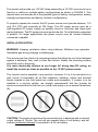
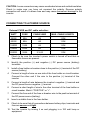
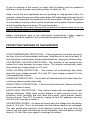
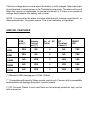
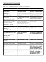
Pure Sine Wave Power Inverter OWNER’S MANUAL Featured Design • • • • High efficiency- save battery Compact size- portable Low Idle Current Soft Start Technology THIS MANUAL CONTAINS IMPORTANT INFORMATION REGARDING SAFETY, OPERATION, MAINTENANCE AND STORAGE OF THIS PRODUCT. BEFORE USE, READ AND UNDERSTAND ALL CAUTIONS, WARNINGS, INSTRUCTIONS AND PRODUCT LABELS, PLUS YOUR VEHICLE’S BATTERY MANUFACTURER GUIDELINES. FAILURE TO DO SO COULD RESULT IN INJURY AND/OR PROPERTY DAMAGE. IMPORTANT SAFETY INSTRUCTIONS To ensure reliable service, your power inverter must be installed and used properly. Please read the installation and operating instructions thoroughly prior to installation and use. Pay particular attention to the WARNING and CAUTION statements in this manual. The CAUTION statements advise against certain conditions and practices that may result in damage to your inverter. The WARNING statements identify conditions or practices that may result in personal injury. Read All Instructions Before Using This Power Inverter! WARNINGS: TO REDUCE THE RISK OF FIRE, ELECTRIC SHOCK, EXPLOSION OR INJURY: 1. Do not connect to AC distribution wiring. This inverter is NOT grid interactive. 2. Remove appliance plug from outlet strip or turn off inverter before working on the appliance. Multiple outlet power strips with switches and circuit breakers only interrupt power to the “hot” receptacle terminals. The “neutral” terminals remain powered with respect to the “ground” terminals. 3. Do not make any electrical connections or disconnections in areas designated as IGNITION PROTECTED. This includes 12 V DC cigarette plug connections, and terminal connections. 4. This is not a toy - keep away from children. 5. DO NOT install object into air vents. CAUTIONS: 1. Do not use with positive ground electrical systems (the majority of modern automobiles, RVs, trucks and boats are negative ground). Reverse polarity connection will result in a blown fuse and may cause permanent damage to the inverter. 2. This inverter will not operate high wattage appliances over the output power limit or surge power limit. 3. Grounding the neutral will cause the inverter to shut down. Do not operate this inverter if it is wet. Do not install in engine compartment – please install in a well ventilated area. 4. This inverter is not tested for use with medical devices. IMPORTANT CABLE INFORMATION Substantial power loss and reduced battery operating time results from inverters installed with cables that are not able to supply full power. Symptoms of low battery power can result from cables that are either excessively long or an insufficient gauge. The installer/operator should be especially aware of the requirements to maintain secure, tight, water-resistant electrical connections and to provide for strain relief for DC cables and appliance wiring. Cable insulation must be the appropriate type for the environment. HOW YOUR INVERTER WORKS The inverter converts low voltage DC (Direct Current) from a battery or other power source to standard 115 volt AC (Alternating Current) household power. PRINCIPLE OF OPERATION The inverter converts power in two stages. The first stage is a DC to DC conversion process that raises the low voltage DC at the inverter input to 150 volts DC. The second stage is the actual inverter stage that converts the high voltage DC into 115 volts, 60 Hz AC(rms). The DC-to-DC converter stage uses modern high frequency power conversion techniques that have replaced the bulky transformers found in less technologically-advanced models. The inverter stage uses advanced power MOSFET transistors in a high frequency full bridge configuration. THE OUTPUT WAVEFORM The AC output waveform of the inverter is known as “Pure Sine Wave” or “True Sine Wave”. It is a waveform that has characteristics same to the sine wave shape of utility power. (See Figure 1). FIGURE 1 : Pure Sine Wave Waveform INSTALLATION / ENVIRONMENTS POWER SOURCE REQUIREMENTS The power source must provide between 10.5 and 15.5 volts DC and must be able to supply the necessary current to operate the load. The power source may be a battery or a well-regulated DC power supply. To obtain a rough estimate of the current (in amperes) the power source must deliver, simply divide the power consumption of the load (in watts AC) by 10. Example: lf a load is rated at 100 watts AC, the power source must be able to deliver: 100 / 10=10A The inverter will provide you 115 VAC when powered by a 12 VDC source such as is found in a vehicle or multiple battery configurations as shown in FIGURE 2. This manual does not describe all of the possible types of battery configurations, battery charging configurations and battery isolation configurations. To properly operate the inverter the DC power source must provide between 11.0 and 15.0 VDC and nominally at 100 Amps. This DC power source must be a well-regulated DC power supply as typically found in vehicular and deep-cycle marine batteries. The DC power source may also be two 12 volt batteries connected in parallel. On larger applications the power source may be several batteries connected in parallel. INSTALLATION NOTES: WARNING: Keeping ventilation when using batteries. Batteries may generate flammable gas during charging or discharging. The inverter has four slots in its mounting bracket that allow the unit to be fastened against a bulkhead, floor, wall or other flat surface. Ideally, the mounting surface should be cool to the touch. It is more electrically efficient to use longer AC wiring than DC wiring, so install the inverter as close as possible to the 12 VDC power source. The inverter can be operated in any position, however, if it is to be mounted on a wall, mount it horizontally (#) so that indicators, switches, outlets and terminal blocks located on the front panel are visible and accessible. If inverter is to be installed in a moving vehicle, we strongly recommends that the inverter be shock-mounted either on the floor (in a clear, safe area) or on a secure flat surface. (#): CAUTION: The power inverter must be connected only to batteries with a nominal output voltage of 12volts. The unit will not operate from a 6 volt battery, and will sustain permanent damage if connected to a 24 volt battery. CAUTION: Loose connectors may cause overheated wires and melted insulation. Check to make sure you have not reversed the polarity. Reverse polarity connection will result in a blown fuse and may cause permanent damage to the inverter. CONNECTING TO A POWER SOURCE External FUSE and DC cable selection: WATT FUSE CABLE AWG MAX. CABLE LENGTH 350W 50A #8 1.5M 600W 80A #6 1.5M 1000W 150A #4 1.2M 1500W 200A #2 1.2M 2000W 300A 2 X #2 1.0M 1. Check to be sure the inverter’s power switch is turned off and that no flammable fumes are present. 2. Identify the positive (+) and negative (-) DC power source (battery) terminals. 3. Install a fuse holder or breaker close to the positive (+) terminal of the DC source (battery). 4. Connect a length of wire on one side of the fuse holder or circuit breaker. Connect the other end if the wire to the positive (+) terminal of the inverter. 5. Connect a length of wire between the inverter’s negative (-) terminal and the DC power source negative (-) terminal. 6. Connect a short length of wire to the other terminal of the fuse holder or circuit breaker. Mark it “POSITIVE” or “+”. 7. Connect the free end of the fuse or breaker wire to the positive terminal of the DC power source (battery). 8. Insert a suitable fuse in the fuse holder. 9. Check to be sure that all connections between battery clips, terminals and fuse are secure and tight. 10. Test the inverter by turning it on and plugging in a 100 watt lamp or equipment. 11. If the inverter is not properly operating, then refer to the troubleshooting sections of this manual. CAUTION: Loose connectors may cause overheated wires and melted insulation. CONNECTION TO LOAD Plug the cord from the equipment you wish to operate into the AC receptacle. The green LED indicator lights to indicate that the inverter is functioning. Make sure the combined load requirement of your equipment does not exceed inverter’s output rating. The inverter is engineered to be connected directly to standard electrical and electronic equipment in the manner described above. Do not connect the power inverter to household or RV AC distribution wiring. Do not connect the power inverter to any AC load circuit in which the neutral conductor is connected to ground (earth) or to the negative of the DC (battery) source. WARNING: Do not connect to AC distribution wiring. This inverter is NOT grid interactive. OPERATING ENVIRONMENT For best operating results, the inverter should be placed on flat surface, such as the ground, car floor, or other solid surface. The power cord allows easy positioning of the inverter. The inverter should only be used in locations that meet the following criteria: DRY- Do not allow water and/or other liquids to come into contact with the power inverter. In all marine applications, do not install the inverter below or near the waterline and keep the inverter away from moisture or water. COOL – Ambient air temperature should be between 30 degrees F (-1 degree C) non-condensing, and 105 degrees F (40 degrees C). Do not place the inverter on or near a heating vent or any piece of equipment which is generating heat above room temperature. Keep the inverter away from direct sunlight, if at all possible. VENTILATED – Keep the area surrounding the inverter clear to ensure free air circulation around the unit. Do not place items on or over the inverter during operation. A fan is helpful if the inverter is operating at maximum power outputs for extended periods of time. The unit will shut down if the internal temperature exceeds operating temperatures. The unit will restart after it cools. SAFE – Do not use the inverter near flammable materials or in any locations that may accumulate flammable fumes of gases. OPERATING TIPS RATED VERSUS ACTUAL CURRENT DRAW OF EQUIPMENT Most electrical tools, appliances and audio/video equipment have labels that indicate the power consumption in amps or watts. Be sure that the power consumption of the item you wish to operate is less than inverter’s power. (If the power consumption is rated in amps AC, simply multiply by the AC volts (115) to determine the wattage). The inverter will shut down if it is overloaded. The overload must be removed before the inverter will restart. Resistive loads are the easiest for the inverter to run. However, larger resistive loads, such as electric stoves or heaters, usually require more wattage than the inverter can deliver. Inductive loads, such as TV’s and stereos, require more current to operate than do resistive loads of the same wattage rating. Induction motors, as well as some televisions, may require 2 to 6 times their wattage rating to start up. The most demanding in this category are those that start under load, such as compressors and pumps. To restart the unit after a shutdown due to overloading, remove the overload if necessary turn the power switch OFF then ON. DETERMINING BATTERY SIZE The power inverter will require DEEP CYCLE lead acid batteries of appropriate capacity. The automotive SLI (Starting/lighting/Ignition) battery is not designed for repeated deep discharge. The SLI battery may not supply enough energy and its service life may be reduced. To determine the minimum battery size that you will need to operate appliances, follow these steps: 1. Determine the wattage of each appliance and/or tool you will need to simultaneously operate from the inverter. To do this, read the labels on the equipment to be operated. Usually, power consumption is shown in watts. If it is shown in amps, multiply by 115 to determine the wattage. 2. Estimate the number of hours the equipment will be in use between battery recharges. 3. Determine the total watt-hours of energy use, the total running time and the average power consumption. To get an estimate of the current (in amps) that the battery must be capable of delivering, divide the load consumption power (in watts) by (10). Keep in mind that most appliances are not operating for long periods of time. For example, a typical home-use coffee maker draws 500 watts during its brew time of 5 minutes, but it maintains the temperature of the pot at about 100 watts. Typical use of a microwave is only for a few minutes, sometimes at low power. Some exceptions to brief operating times are lamps, TVs and computers. In most instances, the inverter can be left connected to the battery when not in use, make sure power switch is in the OFF position. Battery performance drop in low environment temperatures. Higher capacity batteries should be installed if the environment temperature below 20oC. PROTECTIVE FEATURES OF THE INVERTER OVER TEMPERATURE PROTECTION – If the temperature inside the inverter is too high, the unit will automatically shut down. Allow the unit to cool for at least 15 minutes before restarting after a heat-related shutdown. Unplug unit while cooling. LOW BATTERY VOLTAGE PROTECTION - This condition is not harmful to the inverter but could damage the power source. The inverter automatically shuts down when input voltage drops to 10.5 volts. OVER VOLTAGE PROTECTION – The inverter will automatically shut down when the input voltage exceeds 15.0 volts DC. Input voltage exceeds 16 volts could damage the inverter. OVERLOAD PROTECTION – The inverter will automatically shut down when the continuous draw exceeds rated watts. SHORT CIRCUIT PROTECTION – The inverter will shut down. Remove the short circuit and restart inverter. EARTH FAULT PROTECTION – This inverter comply with the standard current leakage allowance. When large current leakage to earth terminal occurs, the protection circuit activated and shut down the inverter, which prevent electric shock to human. Turn OFF the inverter, unplug the fault AC appliance and then turn ON is the only way to restart it. LOW BATTERY ALARM – An alarm will sound when the voltage from the battery drops to 10.6 volts. This is an indication that the battery needs to be recharged. The user should stop operation of the electronic device at this time since the inverter will shut down automatically shortly thereafter, when the battery voltage drops to 10 volts. Start your engine to recharge the battery. If the low voltage alarm sounds when the battery is fully charged, follow the steps for solving lack of output power in the Troubleshooting guide. The alarm will sound when the inverter is overloaded, in thermal shutdown, or if there is an excessive voltage drop between the battery and inverter. NOTE: It is normal for the alarm to sound while the unit is being connected to, or disconnected from, the power source. This is not indicative of a problem. SPECIAL FEATURES USB port(*) 350W 600W 1000W 1500W 2000W Remote Control port (**) No. of AC Outlet DC Terminal Cover(^) SMART FAN YES NO 2 NO YES YES NO 2 NO YES NO YES 2 YES YES NO YES 2 YES YES NO YES 2 YES YES (*) Standard USB charging port +5Vdc, 500mA (**) Compatible with specify Voltec remote control only. Connect with incompatible remote/cable will damage the power inverter/remote. (^) DC Terminal Plastic Covers and Nuts are for terminal protection only, not for wire connection. TROUBLESHOOTING GUIDE TABLE 1 – INVERTER POWER SWITCH TURNED ON TROUBLE/ INDICATION No AC output; Yellow LED lit Green LED not lit No AC output; Red & Green LED not lit Non-continuous AC output; Red LED lit on & off POSSIBLE CAUSE SUGGESTED REMEDY Low battery voltage Recharge or replace battery Inverter overheatthermal shutdown Remove or reduce load, wait for inverter to cool. DC cable loosen or Inverter Check cable connection Or fuses open contact technical support Inverter output power limited by overload / surge circuit protection circuit Reduce load. Green LED lit on & off No AC output (latch up); Red LED lit Unplug the faulted load and Inverter shut down by overload / surge /earth fault wait 2 mins for inverter to cool. protection circuit. Green LED not lit (For models with GFCI only) Inverter shut down by ground fault. Remove the ground faulted AC load and reset the unit. Low battery alarm sounds abnormal Bad connection or wiring Tighten all DC connections Low battery alarm sounds Low battery voltage Recharge or replace battery Motorized power tool won’t start Excessive start-up load If appliance does not start, then appliance is drawing excessive wattage and will not work with inverter Motorized power tool does not operate at correct speed Purely inductive load Make the load not purely inductive. Operate an incandescent lamp at same time as motor No AC output (latch up); Red LED not lit Green LED lit FUSE REPLACEMENT This inverter is protected by our integral electronic circuit and will automatically reset. More than that, this inverter is equipped with a fuse that is located inside the inverter. Normally, this fuse will not blow unless there is a serious problem occurs. Please DO NOT replace the fuse yourself, we recommend you contact technician to find and fix the problems. High voltage and high temperature inside! CAUTION: NO USER-SERVICEABLE COMPONENTS INSIDE. DO NOT ATTEMPT TO OPEN THE INVERTER. SPECIFICATIONS Output Connection………………..……………North America AC Receptacle(s) Output Voltage………………………………….. Approx 115 volt AC RMS 60 Hz Output Waveform……………………………………….Soft Start Pure Sine Wave Max. Efficiency……………………………………………………Approximately 90% Input Voltage …………………………………….….……………12.5 volt DC Input Fuse……………………………………………………………………..Internal