1
Structure and Use of the CPU
___________________
Preface
Memory
1
___________________
Documentation guide
SIMATIC
S7-1500
Structure and Use of the CPU
Memory
Function Manual
01/2013
A5E03461664-01
Memory areas and retentive
2
___________________
memory
Memory usage and
3
___________________
application examples
Legal information
Warning notice system
This manual contains notices you have to observe in order to ensure your personal safety, as well as to prevent
damage to property. The notices referring to your personal safety are highlighted in the manual by a safety alert
symbol, notices referring only to property damage have no safety alert symbol. These notices shown below are
graded according to the degree of danger.
DANGER
indicates that death or severe personal injury will result if proper precautions are not taken.
WARNING
indicates that death or severe personal injury may result if proper precautions are not taken.
CAUTION
indicates that minor personal injury can result if proper precautions are not taken.
NOTICE
indicates that property damage can result if proper precautions are not taken.
If more than one degree of danger is present, the warning notice representing the highest degree of danger will
be used. A notice warning of injury to persons with a safety alert symbol may also include a warning relating to
property damage.
Qualified Personnel
The product/system described in this documentation may be operated only by personnel qualified for the specific
task in accordance with the relevant documentation, in particular its warning notices and safety instructions.
Qualified personnel are those who, based on their training and experience, are capable of identifying risks and
avoiding potential hazards when working with these products/systems.
Proper use of Siemens products
Note the following:
WARNING
Siemens products may only be used for the applications described in the catalog and in the relevant technical
documentation. If products and components from other manufacturers are used, these must be recommended
or approved by Siemens. Proper transport, storage, installation, assembly, commissioning, operation and
maintenance are required to ensure that the products operate safely and without any problems. The permissible
ambient conditions must be complied with. The information in the relevant documentation must be observed.
Trademarks
All names identified by ® are registered trademarks of Siemens AG. The remaining trademarks in this publication
may be trademarks whose use by third parties for their own purposes could violate the rights of the owner.
Disclaimer of Liability
We have reviewed the contents of this publication to ensure consistency with the hardware and software
described. Since variance cannot be precluded entirely, we cannot guarantee full consistency. However, the
information in this publication is reviewed regularly and any necessary corrections are included in subsequent
editions.
Siemens AG
Industry Sector
Postfach 48 48
90026 NÜRNBERG
GERMANY
A5E03461664-01
Ⓟ 01/2013 Technical data subject to change
Copyright © Siemens AG 2013.
All rights reserved
Preface
Purpose of the documentation
This documentation describes the various memory areas of the S7-1500 CPU, and shows
you how to make the best use of these memory areas.
The manual also shows you how to free work memory by using recipes and Data Logs.
Basic knowledge required
The following knowledge is required in order to understand the documentation:
● General knowledge of automation technology
● Knowledge of the SIMATIC industrial automation system
● Knowledge about the use of computers
● Knowledge of working with the TIA Portal and STEP 7
Conventions
Please also observe notes marked as follows:
Note
A note contains important information on the product described in the documentation, on the
handling of the product and on the section of the documentation to which particular attention
should be paid.
Scope of the documentation
This documentation is valid for all CPUs of the S7-1500 product family.
Additional support
● The range of technical documentation for the individual SIMATIC products and
automation systems can be found on the Internet
(http://www.siemens.com/simatic-tech-doku-portal).
● The online catalog and the ordering system are available on the Internet
(www.siemens.com/industrymall).
Structure and Use of the CPU Memory
Function Manual, 01/2013, A5E03461664-01
3
Preface
Structure and Use of the CPU Memory
4
Function Manual, 01/2013, A5E03461664-01
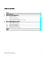
Table of contents
Preface ...................................................................................................................................................... 3
1
Documentation guide................................................................................................................................. 7
2
Memory areas and retentive memory ........................................................................................................ 9
3
2.1
CPU memory areas .......................................................................................................................9
2.2
Retentive memory areas..............................................................................................................13
2.3
Summary of retentive behavior ....................................................................................................16
2.4
Memory behavior when loading software changes......................................................................18
Memory usage and application examples................................................................................................ 21
3.1
Memory usage for recipes ...........................................................................................................21
3.2
3.2.1
3.2.2
3.2.3
3.2.4
Memory usage for data logging ...................................................................................................25
Overview of data logging .............................................................................................................25
Data structure of the data logs.....................................................................................................26
Instructions for data logging.........................................................................................................27
Example program for data logging...............................................................................................28
Glossary .................................................................................................................................................. 35
Index........................................................................................................................................................ 39
Structure and Use of the CPU Memory
Function Manual, 01/2013, A5E03461664-01
5
Table of contents
Structure and Use of the CPU Memory
6
Function Manual, 01/2013, A5E03461664-01
1
Documentation guide
Introduction
This modular documentation of the SIMATIC products covers diverse topics concerning your
automation system.
The complete documentation for the S7-1500 system consists of a system manual, function
manuals and device manuals.
The STEP 7 information system (Online Help) also helps you configure and program your
automation system.
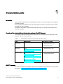
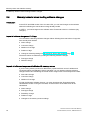
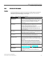
Overview of the documentation on the structure and use of the CPU memory
The following table lists additional documentation which supplements this description of the
structure and use of CPU memory.
Table 1- 1
Documentation on the structure and use of the CPU memory
Topic
Documentation
Most important contents
STEP 7
(TIA Portal)
STEP 7 online help
•
Retentivity of data blocks
•
Working with Data Logs
•
Working with recipes
System
description
System manual S7-1500 Automation
System
(http://support.automation.siemens.com/
WW/view/en/59191792)
•
Memory reset
•
SIMATIC memory card
Description of the
central modules
Manual CPU 1511-1 PN
(http://support.automation.siemens.com/
WW/view/en/59402190)
•
Size of the memory areas
•
Technical specifications
Manual CPU 1513-1 PN
(http://support.automation.siemens.com/
WW/view/en/59186494)
Manual CPU 1516-3 PN/DP
(http://support.automation.siemens.com/
WW/view/en/59191914)
SIMATIC manuals
All current manuals for the SIMATIC products are available for download free of charge from
the Internet (http://www.siemens.com/automation/service&support).
Structure and Use of the CPU Memory
Function Manual, 01/2013, A5E03461664-01
7
Documentation guide
Structure and Use of the CPU Memory
8
Function Manual, 01/2013, A5E03461664-01
Memory areas and retentive memory
2.1
2
CPU memory areas
Introduction
This chapter describes the memory structure of S7-1500 CPUs.
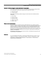
CPU memory areas
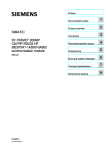
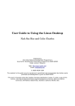
The following figure shows the CPU memory areas and the load memory on the SIMATIC
memory card. In addition to the load memory, the SIMATIC memory card may also contain
other data, such as recipes, Data Logs and HMI backups.
&RGHZRUNPHPRU\
ವ&RGHEORFNV)&)%2%
'DWDZRUNPHPRU\
ವ*OREDOGDWDEORFNV
ವ,QVWDQFHGDWDEORFNV
ವ7HFKQRORJ\REMHFWV
/RDGPHPRU\
RQ6,0$7,&PHPRU\FDUG
ವ&RGHEORFNV)&)%2%
ವ'DWDEORFNV'%
ವ+DUGZDUHFRQILJXUDWLRQ
ವ7HFKQRORJ\REMHFWV
5HWHQWLYHPHPRU\
3DUWVRI
ವ*OREDOGDWDEORFNV
ವ,QVWDQFHGDWDEORFNV
ವ7HFKQRORJ\REMHFWV
ವ%LWPHPRULHVWLPHUVDQGFRXQWHUV
$GGLWLRQDOPHPRU\DUHDV
ವ%LWPHPRULHVWLPHUVDQGFRXQWHUV
ವ7HPSRUDU\ORFDOGDWD
ವ3URFHVVLPDJHV,2
Figure 2-1
CPU memory areas
Structure and Use of the CPU Memory
Function Manual, 01/2013, A5E03461664-01
9
Memory areas and retentive memory
2.1 CPU memory areas
Load memory
The load memory is a non-volatile memory for code blocks, data blocks, technology objects,
and hardware configuration. When these objects are downloaded to the CPU they are first
saved into load memory. This memory is located on the SIMATIC memory card.
Note
To run the CPU, a SIMATIC memory card must be inserted.
Work memory
The work memory is volatile memory that contains the code and data blocks. The work
memory is integrated into the CPU and cannot be extended.
In the S7-1500 CPUs, the work memory is divided into two areas:
● Code work memory: The code work memory contains runtime-relevant parts of the
program code.
● Data work memory: The data work memory contains the runtime-relevant parts of the
data blocks and technology objects. At the operating mode transitions POWER ON to
startup and STOP to startup, tags from global data blocks, instance data blocks and
technology objects are initialized with their start values; retentive tags retain their actual
values as saved in the retentive memory.
Retentive memory
Retentive memory is non-volatile memory for saving a limited quantity of data in the event of
power failure. The tags and operand areas that have been defined as retentive are saved in
retentive memory. These data is retained beyond a power-off or power failure. All other
program tags are lost under these conditions and are set to their start values upon the
operating mode transitions POWER ON to startup, and STOP to startup.
The content of retentive memory is deleted by the following actions:
● Memory reset
● Reset to factory settings
Specified tags from technology objects are also stored in retentive memory. These tags are
not deleted during memory reset.
You can find additional information on the "Memory reset" topic in the Commissioning
chapter of the S7-1500 Automation System
(http://support.automation.siemens.com/WW/view/en/59191792) system manual .
Structure and Use of the CPU Memory
10
Function Manual, 01/2013, A5E03461664-01
Memory areas and retentive memory
2.1 CPU memory areas
Information on memory areas in STEP 7
In STEP 7 you can view the offline and online information about the memory areas of your
S7-1500 CPU.
Offline: When you are creating or modifying a program, you can determine whether it is too
large for a specific CPU. You can find this information under "Program information" in the
project tree, for example. On the Resources tab, you can find information about the total size
of the memory areas, and the storage space that has already been allocated. In this location
you can also find information about the assigned inputs and outputs. With a S7-1500 CPU,
you can select the total size of the load memory in a drop-down list.
The following figure shows the drop-down list for selecting the size of the load memory:
Figure 2-2
Drop-down list for the load memory
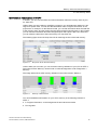
Online: While you are online, you can check the memory utilization of your CPU in STEP 7.
The online function "Memory" can be found in Online & Diagnostics under "Diagnostics >
Memory".
The image below shows CPU memory utilization in the online function "Memory":
Figure 2-3
"Memory" online function
You can find additional information on your CPU's memory in the following locations in
STEP 7:
● In Program information, on the Assignment list and Call structure tabs
● PLC tag table
Structure and Use of the CPU Memory
Function Manual, 01/2013, A5E03461664-01
11
Memory areas and retentive memory
2.1 CPU memory areas
Additional memory areas
Besides the memory areas that have been described for the user program and data, the
CPU has additional memory areas available.
The additional memory areas include the following:
● Bit memories, timers and counters
● Temporary local data
● Process images
The CPU-specific sizes can be found in the technical specifications for the respective CPU.
Reference
You can find additional information on the SIMATIC memory card in the S7-1500 Automation
System (http://support.automation.siemens.com/WW/view/en/59191792) system manual in
the SIMATIC memory card chapter.
Structure and Use of the CPU Memory
12
Function Manual, 01/2013, A5E03461664-01
Memory areas and retentive memory
2.2 Retentive memory areas
2.2
Retentive memory areas
Introduction
The S7-1500 CPUs have memory available for storing retentive data at POWER-OFF.
Details about the size of the retentive memory can be found in the technical specifications for
the CPU.
In STEP 7, you can find the configured CPU's retentive memory utilization offline at
"Program information > Resources" or online at Online & Diagnostics under "Diagnostics >
Memory".
If you define data as retentive, its content is retained beyond program startup after STOP, or
a power failure.
You can define the following data and objects as retentive:
● Bit memories, timers and counters
● Tags from global data blocks
● Tags from instance data blocks of a function block
Certain tags of technology objects are always retentive, for example, adjustment values of
absolute encoders.
Bit memories, timers and counters
In STEP 7, you can define the number of retentive bit memories, timers and counters in the
PLC tag table using the "Retentive memory" button.
Figure 2-4
Definition of the number of retentive bit memories, timers and counters using the "Retentive memory" button
Structure and Use of the CPU Memory
Function Manual, 01/2013, A5E03461664-01
13
Memory areas and retentive memory
2.2 Retentive memory areas
Tags from a global data block
In a global data block, you can define either individual tags from a block or all of its tags
collectively as retentive, depending on the setting for the "Optimized block access" attribute:
● "Optimized block access" activated: In the declaration table of the data block, you can
define individual tags as retentive.
Figure 2-5
Retentivity setting "Optimized block access" activated
● "Optimized block access" not activated: In the declaration table of the data block, you can
only define the Retentivity for all tags collectively.
Figure 2-6
Retentivity setting "Optimized block access" not activated
Tags from an instance data block of a function block
In STEP 7, you can define the tags from the instance data block of a function block as
retentive. Depending on the setting for the "Optimized block access" attribute, you can define
retentivity either for individual tags from a block or for all of its tags collectively:
● "Optimized block access" activated: In the interface of the function block, you can define
individual tags as retentive.
● "Optimized block access" not activated: In the instance data block, you can only define
the retentivity of all tags collectively.
Creation of a data block in the user program
You use the "CREATE_DB" instruction to create a data block in the user program.
Depending on the selection for the ATTRIB parameter, the generated data block either has
the property "retentive" or the property "non-retentive". Setting the retentivity for individual
tags is not possible here.
You can find additional information on the "CREATE_DB" instruction in the STEP 7 online
help under "PLC programming > References > References (S7-1200/1500) > Extended
instructions > Data block functions > CREATE_DB".
Structure and Use of the CPU Memory
14
Function Manual, 01/2013, A5E03461664-01
Memory areas and retentive memory
2.2 Retentive memory areas
Tags of technology objects
Certain tags of technology objects are retentive, for example adjustment values of absolute
encoders. STEP 7 automatically manages the retentivity of technology object tags, so you do
not have to configure their retentivity.
The retentive tags of technology objects are unaffected by a memory reset. They can only be
deleted by resetting to factory settings.
Reference
You can find additional information on configuring retentivity in the STEP 7 online help.
Structure and Use of the CPU Memory
Function Manual, 01/2013, A5E03461664-01
15
Memory areas and retentive memory
2.3 Summary of retentive behavior
2.3
Summary of retentive behavior
Retentive behavior of the memory objects
This chapter gives an overview of the retentive behavior of memory objects for S7-1500
CPUs. Besides the retentive memory areas described so far, there are additional objects
with retentive behavior, such as the diagnostic buffer. These objects do not allocate any
storage space in the retentive memory.
The following table shows the retentive behavior of the memory objects at the operating
mode transitions STOP to startup and POWER ON to startup, as well as the memoryinfluencing functions Memory Reset and Reset to Factory Settings.
Table 2- 1
Retentive behavior of the memory objects
Memory object
Operating mode transitions
Memory reset
Reset to factory
settings
STOP → STARTUP POWER ON →
STARTUP
Actual values of the data blocks,
instance data blocks
Can be set in the Properties of the DB in
STEP 7.1
-
-
Bit memories, timers and counters
-configured as retentive data
x
x
-
-
Bit memories, timers and counters
- configured as non-retentive
-
-
-
-
Certain retentive tags from
technology objects
(for example, adjustment values of
absolute encoders)
x
x
x
-
Diagnostic buffer entries
(retentive area)
x
x
x
-
Diagnostic buffer entries
(non-retentive area)
x
-
-
-
Operating hours counter
x
x
x
-
Clock time
x
x
x
-
x = content is retained
– = object is initialized
1) For DBs with optimized access the retentive behavior is configurable for specific tags.
Structure and Use of the CPU Memory
16
Function Manual, 01/2013, A5E03461664-01
Memory areas and retentive memory
2.3 Summary of retentive behavior
Diagnostic buffer
With the S7-1500 CPUs, a portion of the diagnostic buffer is retentive. The number of
retentive diagnostic buffer entries depends on the type of CPU. The latest entries in the
diagnostic buffer are retained after power failure, and are not affected by a memory reset
The retentive portion of the diagnostic buffer can only be deleted by resetting to factory
settings. The entries in the diagnostic buffer allocate no storage space in the retentive
memory.
Operating hours counter
The operating hours counters of the S7-1500 CPUs are retentive and are not affected by a
memory reset. By resetting to factory settings, the clock time is set to zero.
Clock time
The clock time of the S7-1500 CPUs is retentive and is not affected by a memory reset. By
resetting to factory settings, the operating hours counters are set to 01/01/2012 00:00:00.
Reference
You can find additional information on Memory Reset and Resetting to Factory Settings in
the S7-1500 Automation System
(http://support.automation.siemens.com/WW/view/en/59191792) system manual.
Structure and Use of the CPU Memory
Function Manual, 01/2013, A5E03461664-01
17
Memory areas and retentive memory
2.4 Memory behavior when loading software changes
2.4
Memory behavior when loading software changes
Introduction
In the STOP and RUN modes of the S7-1500 CPU, you can load changes to the software
without this affecting the actual values of tags already loaded.
In STEP 7, you load changes to the software under "Download to device > Software (only
changes)".
Impact of software changes on PLC tags
You can load the following software changes without affecting the actual values of tags that
have already been loaded:
● Name change
● Comment change
● Addition of new tags
● Deletion of tags
● Change of retentivity settings for Bit memories, times, and counters (Page 13)
The actual values are affected by loading the following software changes:
● Data type change
● Address change
Impacts of software changes on data blocks with memory reserve
If you are using memory reserve for data blocks ("Optimized block access" attribute and
"Download without reinitialization" button activated), you can load the following software
changes without this reinitializing the actual values of tags which have already been loaded:
● Start value change
● Comment change
● Addition of new tags
To load the following software changes, you must deactivate the "Download without
reinitialization" button. During the next load, all actual values of the data block will be
reinitialized:
● Name change
● Data type change
● Retentivity change
● Deletion of tags
● Changes to the memory reserve settings
Structure and Use of the CPU Memory
18
Function Manual, 01/2013, A5E03461664-01
Memory areas and retentive memory
2.4 Memory behavior when loading software changes
Impacts of software changes on data blocks without memory reserve
If you are not using memory reserve, you can load the following software changes without
this reinitializing the actual values of tags that have already been loaded:
● Start value change
● Comment change
When loading the following software changes, all actual values of the data block will be
reinitialized:
● Name change
● Data type change
● Retentivity change
● Addition of new tags
● Deletion of tags
Memory reserve of data blocks
Each function block or data block with the "Optimized block access" attribute activated
contains, by default, a memory reserve which you can use for subsequent interface changes.
The memory reserve is initially not used. When you have compiled and loaded the block,
and then observe that you want to reload interface changes, activate the memory reserve.
All tags that you subsequently declare will be placed in the memory reserve. During the next
load, the new tags are then initialized to their start values. Tags which have already been
loaded are not reinitialized.
The setting for memory reserve can be found in STEP 7 in the data block properties under
"Download without reinitialization".
Reference
You can find additional information on setting and activating the memory reserve, and on
loading block changes, in the online help for STEP 7 under "PLC programming > Create
user program > Compile and download blocks > Download blocks > Download block
extensions without reinitialization".
Structure and Use of the CPU Memory
Function Manual, 01/2013, A5E03461664-01
19
Memory areas and retentive memory
2.4 Memory behavior when loading software changes
Structure and Use of the CPU Memory
20
Function Manual, 01/2013, A5E03461664-01
Memory usage and application examples
3.1
3
Memory usage for recipes
Introduction
A recipe represents a collection of parameter records with the same structure. These recipe
data records are located in a non-runtime-relevant data block in the load memory, and do not
occupy any storage space in the work memory. You have the option of reading individual
recipe data records into a data block in work memory, and to access the data in the user
program. You can write a recipe data record that has been changed in the user program
back to the recipe data block.
Structure and Use of the CPU Memory
Function Manual, 01/2013, A5E03461664-01
21
Memory usage and application examples
3.1 Memory usage for recipes
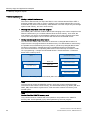
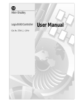
Processing sequence
● Saving a recipe in load memory
The various data records of a recipe are filled in a non-runtime-relevant DB in STEP 7
and then loaded to the CPU. In order to configure a non-runtime-relevant DB, you must
activate the Only store in load memory" block attribute. Thus the recipes only use storage
space in load memory, and not in work memory.
● Working with recipe data in the user program
The "READ_DBL" instruction reads a data record belonging to the current recipe from the
DB in the load memory to a runtime-relevant DB in the work memory. As a result, the
work memory only has to accommodate the data for the currently required recipe data
record. The user program can now access the data of the current data record.
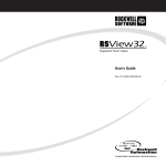
● Saving back changed recipe data records
You can use the "WRIT_DBL" instruction to write new or changed data records of a
recipe from the user program back to the load memory. The data written to load memory
are portable and not affected by a memory reset. If you back up changed data records
(recipes) on the PG/PC, data blocks must be uploaded and saved on the PG/PC.
You can find information on uploading data blocks in the online help for STEP 7 under
"PLC programming > Compile and download blocks > Download blocks > Download
blocks from a memory card".
:RUNPHPRU\
/RDGPHPRU\
&38
6,0$7,&0HPRU\&DUG
5HFLSHGDWDEORFN
5($'B'%/
&XUUHQW
UHFLSHGDWDUHFRUG
:5,7B'%/
5HFLSHGDWDUHFRUG
5HFLSHGDWDUHFRUG
'DWDEORFN
5HFLSHGDWDUHFRUGQ
Figure 3-1
Processing sequence with "READ_DBL" and "WRIT_DBL"
Note
Instructions that access the SIMATIC memory card have a lower performance than
instructions that access the work memory. The associated blocks (e.g. READ_DBL and
WRIT_DBL) are therefore asynchronous. Their execution extends if necessary over
several cycles.
Note
Service life of the SIMATIC memory card
Only a limited number of delete and write operations are possible on the SIMATIC
memory card. Avoid repeated (cyclic) write operations by the user program
Structure and Use of the CPU Memory
22
Function Manual, 01/2013, A5E03461664-01
Memory usage and application examples
3.1 Memory usage for recipes
Import and export of recipe data
You have the option of exporting a recipe DB's recipe data records as a csv file, and of
importing them from a csv file into a DB. The csv file is located in the "\recipes" directory of
the SIMATIC memory card, and can be opened and processed further with a spreadsheet
program such as Microsoft Excel.
You can easily manage the csv files on the SIMATIC memory card using the CPU's web
server (e.g. renaming, saving to hard disk, deleting, ...). In order to prevent unwanted
tampering, configure the access privileges for the web server in STEP 7. Additional
information on the web server can be found in the Web server
(http://support.automation.siemens.com/WW/view/en/59193560) function manual, in the File
Browser chapter.
● Export of recipe data
The "RecipeExport" instruction exports all of a recipe DB's recipe data records from load
memory to a csv file on the SIMATIC memory card. The csv file has the same name as
the DB's recipe. The csv file is stored in the "\recipes" directory on the SIMATIC memory
card.
Only valid and unencrypted recipe data records are exported.
● Import of recipe data
The "RecipeImport" instruction imports all recipe data records from the csv file into the
recipe DB in load memory. The name of the csv file must match the name of the recipe
DB.
6,0$7,&0HPRU\&DUG
/RDGPHPRU\
5HFLSHGDWDEORFN
5HFLSHGDWDUHFRUG
5HFLSHGDWDUHFRUG
5HFLSHGDWDUHFRUGQ
5HFLSH([SRUW
5HFLSH,PSRUW
5HFLSHFVY
Figure 3-2
Import and export of recipe data
Structure and Use of the CPU Memory
Function Manual, 01/2013, A5E03461664-01
23
Memory usage and application examples
3.1 Memory usage for recipes
Reference
You can find further information on the instructions for recipes in the online help for STEP 7
under "PLC programming > References > References (S7-1200/1500) > Extended
instructions > Recipes and data logging > Recipe functions".
Structure and Use of the CPU Memory
24
Function Manual, 01/2013, A5E03461664-01
Memory usage and application examples
3.2 Memory usage for data logging
3.2
Memory usage for data logging
3.2.1
Overview of data logging
Your controller program can store process values in Data Logs using the "Data Logging"
instructions. The Data Logs are saved in csv format in the "\datalogs" directory of the
SIMATIC memory card. The data records are organized in a circular Data Log of a
predefined size.
The "Data Logging" instructions are used in your program to create, open and write
Data Logs and to close Data Logs. You decide which tags are to be logged by creating a
data block that defines a single Data Log data record. Your data block is used as temporary
storage for a new Data Log data record. New actual values for the tags must be transferred
into the data block during runtime by means of user program instructions. Once all tag
values have been updated, you can execute the "DataLogWrite" instruction to transfer data
from the data block to the Data Log.
You manage your Data Logs with the integrated Web server. On the standard "File browser"
Web page, you can download or delete Data Logs. Once you have transferred a Data Log to
your PC, you can analyze the data using a standard spreadsheet program such as Microsoft
Excel.
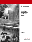
The following figure shows the basic sequence for creating Data Logs:
&38
'%
?GDWDORJV
'RZQORDG
FVY
:HEVHUYHU
0HPRU\
FDUG
'DWDORJJLQJ
LQVWUXFWLRQV
7DJV
Figure 3-3
Basic procedure for creating Data Logs
Structure and Use of the CPU Memory
Function Manual, 01/2013, A5E03461664-01
25
Memory usage and application examples
3.2 Memory usage for data logging
3.2.2
Data structure of the data logs
Introduction
You use the "DataLogCreate" instruction to create a Data Log in STEP 7. The NAME
parameter assigns the Data Log a name. The DATA and HEADER parameters specify the
data type of all data elements in a Data Log data record and the header of the Data Logs.
The RECORDS parameter indicates the maximum number of data records in the Data Logs.
NAME parameter for the "DataLogCreate" instruction
You use the NAME parameter to assign a name for the Data Log. This is the name under
which the Data Log is saved in the "\datalogs" directory of the SIMATIC memory card.
DATA parameter for the "DataLogCreate" instruction
The DATA block parameter specifies the structure of the Data Log data records. The
columns and data types of a data record in the Data Log are determined by the elements of
the structure declaration or array declaration of this data buffer. Each element of a structure
or an array corresponds to a column in a row in the Data Log.
HEADER parameter for the "DataLogCreate" instruction
Using the HEADER block parameter, you can assign a heading in the header row to each
column in the Data Log.
RECORDS parameter for the "DataLogCreate" instruction
The RECORDS parameter specifies the maximum number of data records that can be
stored in a Data Log. If the specified maximum number of data records in a Data Log is
reached, the next write operation will overwrite the oldest data record.
Structure and Use of the CPU Memory
26
Function Manual, 01/2013, A5E03461664-01
Memory usage and application examples
3.2 Memory usage for data logging
3.2.3
Instructions for data logging
Overview
The following table gives an overview of the instructions for Data Logging. You will find the
"Data Logging" instructionsin STEP 7 in the "Instructions" task card, under "Extended
instructions > Recipe and data logging > Data Logging".
Table 3- 1
Overview of the "Data Logging" instructions
Name of the instruction
Description
"DataLogCreate":
Create data log
You use the "DataLogCreate" instruction to create a Data Log. The
Data Log is saved on the SIMATIC memory card in the "\datalogs"
directory. You can use the data logging instructions to save
process data. The amount of data that can be stored in a Data Log
depends on the storage space available on the SIMATIC
memory card.
"DataLogOpen":
Open data log
You use the "DataLogOpen" instruction to open an existing Data
Log on the SIMATIC memory card. Before you can write new data
records to a Data Log, the Data Log must be open.
The Data Log is automatically opened when the "DataLogCreate"
and "DataLogNewFile" instructions are executed.
A maximum of 10 Data Logs can be open at any one time. You
can select the Data Log to be opened using either the ID or the
name of the Data Log.
"DataLogWrite":
Write data log
You use the "DataLogWrite" instruction to write a data record to an
existing Data Log. Use the ID parameter to select the Data Log to
which the data record is to be written. Before a new data record
can be written, the Data Log must be opened.
"DataLogClose":
Close data log
You use the "DataLogClose" instruction to close an open Data
Log. You use the ID parameter to select the Data Log.
All open Data Logs are closed when the CPU switches to STOP.
"DataLogNewFile":
Data log in new file
You use the "DataLogNewFile" instruction to create a new
Data-Log with the same properties as an existing Data Log. By
creating new Data Logs, you prevent cyclic overwriting of existing
data records.
When the instruction is called, it creates a new Data Log on the
SIMATIC memory card with the name defined at the NAME
parameter. Use the ID parameter to specify the ID of the existing
Data Log whose properties you want to apply to the new Data Log.
The ID of the new Data Log is then output at the ID parameter.
"DataLogClear":
Clear data log
Use the "DataLogClear" instruction to delete all data records from
an existing Data Log. The header of the Data Log is not deleted
(see the description of the parameter HEADER of the
"DataLogCreate" instruction (Page 26)).
"DataLogDelete":
Delete data log
You use the "DataLogDelete" instruction to delete a Data Log from
the SIMATIC memory card.
Select the Data Log to be deleted using the NAME and ID
parameters.
Structure and Use of the CPU Memory
Function Manual, 01/2013, A5E03461664-01
27
Memory usage and application examples
3.2 Memory usage for data logging
Reference
You can find further information on "Data Logging" instructions in the online help for STEP 7
under "PLC programming > References > References (S7-1200/1500) > Extended
instructions > Recipes and data logging > Data Logging".
3.2.4
Example program for data logging
This example program shows the storing of 3 process values for counter state, temperature,
and pressure in a Data Log.
The example shows the basic function of the instructions for Data Logs. The complete
program logic is not shown.
Note
General use of Data Logs
• Data Logs are automatically opened after execution of the "DataLogCreate" and
"DataLogNewFile" instructions.
• Data Logs are automatically closed when the CPU switches from RUN to STOP and
upon CPU restart.
• Before data can be written to a Data Log with the "DataLogWrite" instruction, the
Data Log must be open.
• No more than ten Data Logs can be open simultaneously, even if there are more than ten
Data Logs.
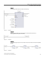
Tags of the data block
The following figure shows the tags of the "My_Datalog_Vars" data block. These tags are
used by the "Data Logging" instructions "DataLogCreate" and "DataLogNewFile". The
"MyDataLogName" and "MyNEWDataLogName" tags are called in the NAME block
parameter, and give the Data Logs a name. The "MyData" structure is called in the DATA
block parameter and specifies the structure of the csv file. The three MyData tags
temporarily store new values. The tag values at these DB addresses are transferred to a
Data Log using the "DataLogWrite" instruction. The "MyDataLogHeaders" tag is called in the
HEADER block parameter and specifies a header for the Data Log.
Figure 3-4
Declaration table with the data block's tags
Structure and Use of the CPU Memory
28
Function Manual, 01/2013, A5E03461664-01
Memory usage and application examples
3.2 Memory usage for data logging
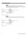
Network 1
A rising edge at REQ starts the creation of the Data Log.
Figure 3-5
Network 1
Network 2
Detect the output DONE from "DataLogCreate", because after the execution of
"DataLogCreate" it is only set to 1 for a call.
Figure 3-6
Network 2
Network 3
A rising edge triggers the point in time at which new process values are stored in the MyData
structure.
Figure 3-7
Network 3
Structure and Use of the CPU Memory
Function Manual, 01/2013, A5E03461664-01
29
Memory usage and application examples
3.2 Memory usage for data logging
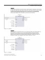
Network 4
The state of the input EN is based on the point in time at which the execution of
"DataLogCreate" was completed. One execution of "DataLogCreate" extends over multiple
cycles, and must be completed before a write operation is executed. The rising edge at input
REQ is the event, that triggers an activated write operation.
Figure 3-8
Network 4
Network 5
Close the Data Log once the last data record has been written. After execution of the
"DataLogWrite" instruction, which writes the last data record, the STATUS output is set to
"1".
Figure 3-9
Network 5
Structure and Use of the CPU Memory
30
Function Manual, 01/2013, A5E03461664-01
Memory usage and application examples
3.2 Memory usage for data logging
Network 6
A rising edge at the REQ input of the instruction "DataLogOpen" simulates the user pressing
a button on an HMI device which opens a Data Log. If you open a Data Log in which all data
records have been allocated process data, the next execution of the "DataLogWrite"
instruction will overwrite the oldest data record. You can, however, also retain the old
Data Log and instead create a new Data Log. This is shown in network 7.
Figure 3-10
Network 6
Network 7
The ID parameter is an IN/OUT type. First, you enter the ID value of the existing Data Log
whose structure you want to copy. Once the "DataLogNewFile" instruction has been
executed, a new and unique ID value for the new Data Log will be written back to the
address of the ID reference. The required detection DONE bit = TRUE is not shown. An
example for the logic of the DONE bit can be found in networks 1, 2 and 4.
Figure 3-11
Network 7
Structure and Use of the CPU Memory
Function Manual, 01/2013, A5E03461664-01
31
Memory usage and application examples
3.2 Memory usage for data logging
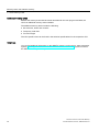
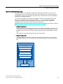
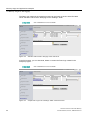
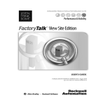
The Data Logs created in the example program can be found on the S7-1500 CPU Web
server standard "File browser" Web page in the "\datalogs" folder.
CPU 1516/SIMATIC S7 CPU 1516 PN/DP
16:43:22
15.11.2012
English
Filebrowser
Admin
Log out
Start page
Identification
Diagnostic buffer
Module information
/
Name
Size
Changed
log
datalogs
recipes
cdrinfo.bin
32768
17097
2525
512
10:22:31 13.11.2012
09:17:43 12.11.2012
07:39:54 12.11.2012
10:22:31 13.11.2012
Delete
Rename
Directory operations:
Messages
Search...
Upload file
Communication
Topology
Costumer pages
Filebrowser
Figure 3-12
Standard "File browser" web page of the web server
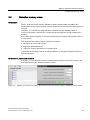
In the file browser, you can download, delete or rename the Data Logs created in the
example program.
CPU 1516/SIMATIC S7 CPU 1516 PN/DP
16:43:22
15.11.2012
English
Filebrowser
Admin
Log out
Start page
Identification
/
Name
Size
Changed
..
mydatalogname.csv
mynewdatalogname.csv
0
99
25
12:00:00 01.01.1970
13:05:39 13.11.2012
17:23:09 13.11.2012
Delete
Rename
Diagnostic buffer
Module information
Directory operations:
Messages
Search...
Upload file
Communication
Topology
Costumer pages
Filebrowser
Figure 3-13
Sample Data Logs in the "\datalogs" folder of the file browser
Structure and Use of the CPU Memory
32
Function Manual, 01/2013, A5E03461664-01
Memory usage and application examples
3.2 Memory usage for data logging
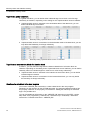
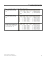
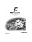
Table 3- 2
Downloaded examples of data logs displayed in Microsoft Excel
Two data records written in a Data Log
which contains a maximum of five data
records.
Five data records written in a Data Log
which contains a maximum of five data
records.
After another data record has been written,
the 6th write operation overwrites the oldest
data record (record 1) with data record 6.
Another write operation overwrites data
record 2 with data record 7, etc.
Structure and Use of the CPU Memory
Function Manual, 01/2013, A5E03461664-01
33
Memory usage and application examples
3.2 Memory usage for data logging
Structure and Use of the CPU Memory
34
Function Manual, 01/2013, A5E03461664-01
Glossary
Bit memory
Bit memory is a memory area of the CPU, which can be addressed from any code block (FC,
FB, OB). You have read/write access to this memory area. The bit memory area can be used
to store temporary results, for example.
Counters
In STEP 7, counting tasks are performed using counters. You can modify the contents of the
"counter cells" using STEP 7 instructions (for example, count up/down).
Data block
Data blocks store information for the program. They can be defined in two ways: either that
all code blocks can access them (global data block), or that they are assigned to a specific
FB or SFB (instance data block).
Data log
Data logs are csv files for the storage of tag values. The data logs are saved on the
SIMATIC memory card in the "\datalogs" directory. Data records of tag values are written to
a data log by means of instructions in the user program
Global data block (DB)
Every function block, every function, and every organization block can read the data from a
global data block, or write its own data to a global data block. This data is retained in the
data block, even when the data block is exited.
Instance data block (IDB)
A data block is assigned to each call of a function block in the STEP 7 user program. The
instance data block stores the values of input, output and in/out parameters, as well as local
block data.
Local data
This memory area accepts the temporary local data of a block for the duration of processing.
Memory reset
During memory reset the CPU is shifted into the configured initial state.
Structure and Use of the CPU Memory
Function Manual, 01/2013, A5E03461664-01
35
Glossary
Optimized block access
Data blocks with optimized access have a no fixed defined structure. In the declaration, the
data elements only receive a symbolic name, and no fixed address within the block. The
elements are automatically so arranged in the block's available memory area, that its
capacity is optimally exploited.
In these data blocks, you can only address tags symbolically. For example, you would
access the "FillState" tag in the "Data" DB as follows:
"Data".FillState
Optimized access offers the following advantages:
● The data is structured and saved in a manner that is optimal for the CPU used. This
allows you to increase CPU performance.
● Access errors, from HMI, for example, are not possible.
● You can selectively define individual tags as retentive.
Process images (I/O)
The CPU transfers the values from the input and output modules in this memory area. At the
start of the cyclic program the signal states of the input modules are transmitted to the
process image of the inputs. At the end of the cyclic program the process image of the
outputs is transmitted as signal state to the output modules.
Reset to factory setting
Resetting to factory settings restores the CPU settings to the delivery state.
Restart
Restart occurs at the transitions from STOP to STARTUP, and POWER ON to STARTUP.
Before processing the cyclic program processing, the CPU first processes the startup OB or
OBs.
Restart has the following effects on the memory areas of the CPU:
● The process images are deleted.
● The retentive tags of data blocks retain the values saved in retentive memory.
● All retentive bit memories, timers, and counters retain the values saved in retentive
memory.
● All non-retentive user data is initialized:
– Data blocks receive their start value
– Bit memories, timers, and counters with "0"
SIMATIC memory card
Memory for the user program for programmable modules and communication processors.
You can also use the SIMATIC memory card for changing user software and user data.
Structure and Use of the CPU Memory
36
Function Manual, 01/2013, A5E03461664-01
Glossary
Standard access
Data blocks with standard access have a fixed structure. In the declaration, the data
elements receive both a symbolic name and a fixed address within the block. The address is
displayed in the "Offset" column.
In these data blocks, you can address tags both symbolically and absolutely.
"Data".FillState
DB1.DBW2
Timers
In STEP 7, programmed time processes are performed using timers. The content of timer
cells is automatically updated by the operating system, asynchronously to the user program.
STEP 7 instructions are used to define the precise function of the timer cell
(for example, on-delay time) and to trigger their execution (for example, start).
User program
The user program contains all instructions, declarations and data for signal processing
required to control a plant or a process. The user program is assigned to a programmable
module (for example, CPU, CM) and can be structured in smaller units.
Structure and Use of the CPU Memory
Function Manual, 01/2013, A5E03461664-01
37
Glossary
Structure and Use of the CPU Memory
38
Function Manual, 01/2013, A5E03461664-01
Index
Behavior of the memory objects, 16
B
Bit memory, 13
C
Counters, 13
D
Data block, 14, 18
Data logging
Data structure, 26
DataLogClear, 27
DataLogClose, 27
DataLogCreate, 26, 27
DataLogDelete, 27
DataLogNewFile, 27, 28
DataLogOpen, 27
DataLogWrite, 27
Example program, 28
Overview of data logging, 25
S
Software change, 18
T
Technology objects, 15
Timers, 13
W
Work memory, 10
F
Function block, 14
L
Load memory, 10
M
Memory areas, 9
Memory reserve, 19
R
Recipe, 21
Recipe data, 23
Retentive memory, 10
Retentivity
Structure and Use of the CPU Memory
Function Manual, 01/2013, A5E03461664-01
39
Index
Structure and Use of the CPU Memory
40
Function Manual, 01/2013, A5E03461664-01