1
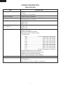
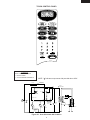
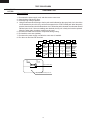
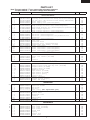
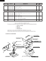
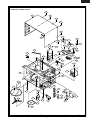
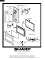
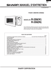
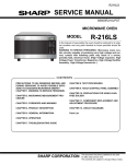
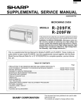
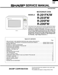
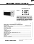
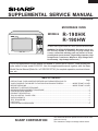
R-190HK
R-190HW
SUPPLEMENTAL SERVICE MANUAL
S1302R190HPW/
MICROWAVE OVEN
MODELS
R-190HK
R-190HW
In the interest of user-safety the oven should be restored to its original
condition and only parts identical to those specified should be used.
WARNING TO SERVICE PERSONNEL: Microwave ovens contain circuitry capable of producing very high voltage and
current, contact with following parts may result in a severe,
possibly fatal, electrical shock. (High Voltage Capacitor, High
Voltage Power Transformer, Magnetron, High Voltage Rectifier Assembly, High Voltage Harness etc..)
This is a supplemental Service Manual for Models R-190HK and R-190HW. These models are
quite similar to base model R-201FW. Use this supplemental manual together with the Base
Model Service Manual (Refer No. is S1201R201FPW/) for complete operation, service information, etc..
TABLE OF CONTENTS
Page
PRECAUTIONS TO BE OBSERVED BEFORE AND DURING SERVICING TO
AVOID POSSIBLE EXPOSURE TO EXCESSIVE MICROWAVE ENERGY ................... INSIDE FRONT COVER
BEFORE SERVICING ...................................................................................................... INSIDE FRONT COVER
WARNING TO SERVICE PERSONNEL ................................................................................................................ 1
MICROWAVE MEASUREMENT PROCEDURE ................................................................................................... 2
FOREWORD AND WARNING ............................................................................................................................... 3
PRODUCT DESCRIPTION .................................................................................................................................... 4
TOUCH CONTROL PANEL VIEW ........................................................................................................................ 5
OVEN SCHEMATIC ............................................................................................................................................... 5
TEST PROCEDURE .............................................................................................................................................. 6
PARTS LIST .......................................................................................................................................................... 7
PACKING AND ACCESSORIES ........................................................................................................................... 8
This document has been published to be used for after
sales service only.
The contents are subject to change without notice.
SHARP CORPORATION
11
R-190HK
R-190HW
PRECAUTIONS TO BE OBSERVED BEFORE AND
DURING SERVICING TO AVOID POSSIBLE EXPOSURE TO EXCESSIVE MICROWAVE ENERGY
(a) Do not operate or allow the oven to be operated with the door open.
(b) Make the following safety checks on all ovens to be serviced before activating the magnetron or other
microwave source, and make repairs as necessary: (1) interlock operation, (2) proper door closing, (3) seal
and sealing surfaces (arcing, wear, and other damage), (4) damage to or loosening of hinges and latches,
(5) evidence of dropping or abuse.
(c) Before turning on microwave power for any service test or inspection within the microwave generating
compartments, check the magnetron, wave guide or transmission line, and cavity for proper alignment,
integrity, and connections.
(d) Any defective or misadjusted components in the interlock, monitor, door seal, and microwave generation
and transmission systems shall be repaired, replaced, or adjusted by procedures described in this manual
before the oven is released to the owner.
(e) A microwave leakage check to verify compliance with the Federal Performance Standard should be
performed on each oven prior to release to the owner.
BEFORE SERVICING
Before servicing an operative unit, perform a microwave emission check as per the Microwave
Measurement Procedure outlined in this service manual.
If microwave emissions level is in excess of the specified limit, contact SHARP ELECTRONICS
CORPORATION immediately @1-800-237-4277.
If the unit operates with the door open, service person should 1) tell the user not to operate the oven
and 2) contact SHARP ELECTRONICS CORPORATION and Food and Drug Administration's
Center for Devices and Radiological Health immediately.
Service personnel should inform SHARP ELECTRONICS CORPORATION of any certified unit
found with emissions in excess of 4mW/cm2. The owner of the unit should be instructed not to use
the unit until the oven has been brought into compliance.
12
R-190HK
R-190HW
WARNING TO SERVICE PERSONNEL
Microwave ovens contain circuitry capable of producing very high voltage and current, contact with
following parts may result in a severe, possibly
fatal, electrical shock.
(Example)
High Voltage Capacitor, High Voltage Power Transformer, Magnetron, High Voltage Rectifier Assembly, High Voltage Harness etc..
Read the Service Manual carefully and follow all
instructions.
Don't Touch !
Danger High Voltage
When the testing is completed,
1. Disconnect the power supply cord, and then remove
outer case.
2. Open the door and block it open.
3. Discharge high voltage capacitor.
4. Reconnect the leads to the primary of the power
transformer.
5. Reinstall the outer case (cabinet).
6. Reconnect the power supply cord after the outer case is
installed.
7. Run the oven and check all functions.
Before Servicing
1. Disconnect the power supply cord
outer case.
2. Open the door and block it open.
3. Discharge high voltage capacitor.
, and then remove
WARNING:RISK OF ELECTRIC SHOCK.
DISCHARGE THE HIGH-VOLTAGE
CAPACITOR BEFORE SERVICING.
After repairing
The high-voltage capacitor remains charged about 60
seconds after the oven has been switched off. Wait for 60
seconds and then short-circuit the connection of the highvoltage capacitor (that is the connecting lead of the highvoltage rectifier) against the chassis with the use of an
insulated screwdriver.
1. Reconnect all leads removed from components during
testing.
2. Reinstall the outer case (cabinet).
3. Reconnect the power supply cord after the outer case is
installed.
4. Run the oven and check all functions.
Whenever troubleshooting is performed the power supply
must be disconnected. It may, in some cases, be necessary
to connect the power supply after the outer case has been
removed, in this event,
1. Disconnect the power supply cord, and then remove
outer case.
2. Open the door and block it open.
3. Discharge high voltage capacitor.
4. Disconnect the leads to the primary of the power
transformer.
5. Ensure that the leads remain isolated from other
components and oven chassis by using insulation tape.
6. After that procedure, reconnect the power supply cord.
Microwave ovens should not be run empty. To test for the
presence of microwave energy within a cavity, place a cup
of cold water on the oven turntable, close the door and set
the power to HIGH and set the microwave timer for two (2)
minutes. When the two minutes has elapsed (timer at zero)
carefully check that the water is now hot. If the water
remains cold carry out Before Servicing procedure and reexamine the connections to the component being tested.
When all service work is completed and the oven is fully
assembled, the microwave power output should be checked
and microwave leakage test should be carried out.
1
R-190HK
R-190HW
MICROWAVE MEASUREMENT PROCEDURE
A. Requirements:
1) Microwave leakage limit (Power density limit): The power density of microwave radiation emitted by a microwave oven
should not exceed 1mW/cm2 at any point 5cm or more from the external surface of the oven, measured prior to acquisition
by a purchaser, and thereafter (through the useful life of the oven), 5 mW/cm2 at any point 5cm or more from the external
surface of the oven.
2) Safety interlock switches: Primary interlock relay and door sensing switch shall prevent microwave radiation emission
in excess of the requirement as above mentioned, secondary interlock switch shall prevent microwave radiation emission
in excess of 5 mW/cm2 at any point 5cm or more from the external surface of the oven.
B. Preparation for testing:
Before beginning the actual measurement of leakage, proceed as follows:
1) Make sure that the actual instrument is operating normally as specified in its instruction booklet.
Important:
Survey instruments that comply with the requirement for instrumentation as prescribed by the performance standard
for microwave ovens, 21 CFR 1030.10(c)(3)(i), must be used for testing.
2) Place the oven tray in the oven cavity.
3) Place the load of 275±15 ml (9.8 oz) of tap water initially at 20±5˚C (68˚F) in the center of the oven cavity.
The water container shall be a low form of 600 ml (20 oz) beaker with an inside diameter of approx. 8.5 cm (3-1/2 in.)
and made of an electrically nonconductive material such as glass or plastic.
The placing of this standard load in the oven is important not only to protect the oven, but also to insure that any leakage
is measured accurately.
4) Set the cooking control on Full Power Cooking Mode
5) Close the door and select a cook cycle of several minutes. If the water begins to boil before the survey is completed,
replace it with 275 ml of cool water.
C. Leakage test:
Closed-door leakage test (microwave measurement)
1) Grasp the probe of the survey instrument and hold it perpendicular to the gap between the door and the body of the oven.
2) Move the probe slowly, not faster than 1 in./sec. (2.5 cm/sec.) along the gap, watching for the maximum indication on
the meter.
3) Check for leakage at the door screen, sheet metal seams and other accessible positions where the continuity of the metal
has been breached (eg., around the switches, indicator, and vents).
While testing for leakage around the door pull the door away from the front of the oven as far as is permitted by the closed
latch assembly.
4) Measure carefully at the point of highest leakage and make sure that the highest leakage is no greater than 4mW/cm2,
and that the secondary interlock switch does turn the oven OFF before any door movement.
NOTE: After servicing, record data on service invoice and microwave leakage report.
2
R-190HK
R-190HW
SERVICE MANUAL
MICROWAVE OVEN
R-190HK/ R-190HW
FOREWORD
This Manual has been prepared to provide Sharp Electronics Corp. Service Personnel with Operation and Service
Information for the SHARP MICROWAVE OVENS, R-190HK and R-190HW.
The models R-190HK and R-190HW are quite similar to base model R-201FW (Refer No. is S1201R201FPW/).
It is recommended that service personnel carefully study the entire text of this manual and the base model's manual so
that they will be qualified to render satisfactory customer service.
Check the interlock switches and the door seal carefully. Special attention should be given to avoid electrical shock and
microwave radiation hazard.
WARNING
Never operate the oven until the following points are ensured.
(A) The door is tightly closed.
(B) The door brackets and hinges are not defective.
(C) The door packing is not damaged.
(D) The door is not deformed or warped.
(E) There is no other visible damage with the oven.
Servicing and repair work must be carried out only by trained service personnel.
DANGER
Certain initial parts are intentionally not grounded and present a risk of electrical shock only during servicing.
Service personnel - Do not contact the following parts while the appliance is energized;
High Voltage Capacitor, Power Transformer, Magnetron, High Voltage Rectifier Assembly, High Voltage
Harness;
If provided, Vent Hood, Fan assembly, Cooling Fan Motor.
All the parts marked “*” on parts list are used at voltages more than 250V.
Removal of the outer wrap gives access to voltage above 250V.
All the parts marked “∆” on parts list may cause undue microwave exposure, by themselves, or when they are
damaged, loosened or removed.
SHARP ELECTRONICS CORPORATION
SHARP PLAZA, MAHWAH,
NEW JERSEY 07430-2135
3
R-190HK
R-190HW
PRODUCT DESCRIPTION
SPECIFICATIONS
ITEM
DESCRIPTION
Power Requirements
120 Volts
60 Hertz
Single phase, 3 wire grounded
Power Consumption
1100W / Approx. 9.6 Amperes
Power Output
650 W nominal of RF microwave energy (IEC Test procedure)
Operating frequency 2450 MHz
Case Dimensions
Width 18-1/8"
Height 10-7/8"
Depth 13-7/8"
Cooking Cavity Dimensions
(0.7 Cubic feet)
Width 12-5/8"
Height 7-7/8"
Depth 13-1/4"
Control Complement
Touch Control System
Clock (1:00 - 12:59)
Timer (0 - 99 minutes 99 seconds)
Microwave Power for Variable Cooking
Repetition Rate;
P-HI ................................... Full power throughout the cooking time
P-90 .................................................... approx. 90% of FULL Power
P-80 .................................................... approx. 80% of FULL Power
P-70 .................................................... approx. 70% of FULL Power
P-60 .................................................... approx. 60% of FULL Power
P-50 .................................................... approx. 50% of FULL Power
P-40 .................................................... approx. 40% of FULL Power
P-30 .................................................... approx. 30% of FULL Power
P-20 .................................................... approx. 20% of FULL Power
P-10 .................................................... approx. 10% of FULL Power
P-0 ...................................... No power throughout the cooking time
EXPRESS DEFROST pad, POPCORN pad
INSTANT START pads, Number selection pads
TIMER/CLOCK pad, POWER LEVEL pad
START/ MINUTE PLUS pad, STOP/CLEAR pad
Oven Cavity Light
Yes
Safety Standard
UL Listed.
FCC Authorized
DHHS Rules, CFR, Title 21, Chapter 1, Subchapter J
4
R-190HK
R-190HW
TOUCH CONTROL PANEL
SCHEMATIC
NOTE: CONDITION OF OVEN
1. DOOR CLOSED
2. CLOCK APPEARS ON DISPLAY
C/T FUSE
NOTE: " " indicates components with potential above 250V.
TEMPERATURE
FUSE (OVEN)
N.O.
POWER
TRANSFORMER
COM.
(RY-2)
(RY-1)
A3
PRIMARY
INTERLOCK
RELAY
CAPACITOR
0.82µF
AC2100V
CONTROL UNIT
A1
B2
B1
GRN
120V AC
60 Hz
DOOR
SENSING
SWITCH
TTM
OL
OVEN
LAMP
TURNTABLE
MOTOR
MONITOR
SWITCH
FM
RECTIFIER
FAN
MOTOR
SECONDARY
INTERLOCK
SWITCH
Figure O-1. Oven Schematic-Off Condition
5
MAGNETRON
R-190HK
R-190HW
TEST PROCEDURES
PROCEDURE
LETTER
J
COMPONENT TEST
KEY UNIT TEST
1.
2.
3.
4.
5.
6.
7.
8.
Disconnect the power supply cord, and then remove outer case.
Open the door and block it open.
Discharge high voltage capacitor.
Using an ohmmeter and referring to the key unit matrix indicated on the control unit circuit, check the
circuit between the pins of the key unit that correspond to the STOP/CLEAR pad. When the pad is
pressed, the ohmmeter should indicate short circuit. When the pad is released, the ohmmeter should
indicate open circuit. If incorrect readings are obtained, the key unit is faulty and must be replaced.
About the other pads, the above method may be used.
Reconnect all leads removed from components during testing.
Re-install the outer case (cabinet).
Reconnect the power supply cord after the outer case is installed.
Run the oven and check all functions.
G1
G7
G3
6
2
G4
G5
G6
FRESH
BEVERAGE POPCORN
VEGETABLES
G8
CASSEROLE
3
5
4
EXPRESS
DEFROST
POWER
LEVEL
G9
ROLLS&
MUFFINS
TIMER
CLOCK
0
1
SOUP
STOP
CLEAR
9
8
7
BAKED
POTATOES
START
MINUTE
PLUS
G10
Pin
NO. G1
G2
Pin
NO. G10
Key unit ribbon cable
Key unit (Membrane Switch) front view
6
R-190HK
R-190HW
PARTS LIST
Note: The parts marked “∆” may cause undue microwave exposure.
The parts marked “*” are used in voltage more than 250V.
REF. NO.
PART NO.
DESCRIPTION
QSW-MA085WRE0
QSW-MA137WRE0
FFS-BA027WRKZ
FACCDA079WRE0
FACCDA064WRE0
FH-DZA102WRKZ
FH-DZA088WRK0
FH-DZA106WRKZ
RC-PZA041WRE0
RC-QZA307WRZZ
RC-QZA308WRZZ
RMOTEA383WRE0
RMOTEA355WRE0
RMOTEA408WRZZ
RV-MZA226WRE0
RV-MZA306WRZZ
RLMPTA082WRZZ
RMOTDA211WRE0
RMOTDA186WRE0
QFS-TA038WRE0
RTRN-A694WRZZ
RTRN-A648WRZZ
RTRN-A642WRZZ
RTRN-A691WRZZ
Secondary interlock switch/ Door sensing switch
Secondary interlock switch/ Door sensing switch (Interchangeable)
C/T fuse (120˚C, 13A) and monitor switch assembly (AM51620C53Y1)
Power supply cord
Power supply cord (Interchangeable)
High voltage rectifier assy
High voltage rectifier assy (Interchangeable)
High voltage rectifier assy (Interchangeable)for production use
High voltage capacitor
High voltage capacitor (Interchangeable)
High voltage capacitor (Interchangeable)
Fan motor
Fan motor (Interchangeable)
Fan motor (Interchangeable) for production use
Magnetron
Magnetron (Interchangeable)
Oven lamp
Turntable motor
Turntable motor (Interchangeable)
Temperature fuse 120deg. C (Oven)
Power transformer
Power transformer (Interchangeable)
Power transformer (Interchangeable)
Power transformer (Interchangeable)
Q'TY
CODE
2
2
1
1
1
1
1
1
1
1
1
1
1
1
1
1
1
1
1
1
1
1
1
1
AF
AH
AS
AF
AP
AN
AP
-AS
AX
AN
AV
AU
-BE
BL
AL
AS
AW
AK
BG
BH
BH
BG
1
1
2
1
BD
BD
AC
AG
1
1
1
1
1
1
1
1
1
1
1
3
BA
BA
AV
AV
AQ
AG
AH
AB
BE
AE
AQ
AA
1
1
1
1
1
1
1
1
2
1
1
1
AM
AF
AK
AR
-AK
AG
AM
AF
AC
AB
AC
1
1
1
1
1
1
1
1
BC
AW
AW
AP
AF
AC
AG
AK
ELECTRIC PARTS
*
*
*
*
*
*
*∆
*∆
*
*
*
*
1- 1
1- 1
1- 2
1- 3
1- 3
1- 4
1- 4
1- 4
1- 5
1- 5
1- 5
1- 6
1- 6
1- 6
1- 7
1- 7
1- 8
1- 9
1- 9
1-10
1-11
1-11
1-11
1-11
CABINET PARTS
2222-
1
1
2
3
GCABUA828WRPZ
GCABUA817WRPZ
GLEGPA074WRE0
PCUSUA605WRPZ
Outer case cabinet [R-190HK]
Outer case cabinet [R-190HW]
Foot
Cushion
333333333333-
1
1
1-1
1-1
1-2
2
2
3
4
5
6
7
FPNLCB737WRKZ
FPNLCB738WRKZ
PSHEPA928WREZ
PSHEPA929WREZ
QSW-KA014DRZZ
JBTN-B175WRFZ
JBTN-B165WRFZ
MSPRCA050WRE0
DPWBFC247WRUZ
QCNC-A014WRZZ
RLCDSA105DRZZ
XEPSD30P08XS0
Control panel frame with key unit [R-190HW]
Control panel frame with key unit [R-190HK]
Graphic sheet [R-190HW]
Graphic sheet [R-190HK]
Membrane switch
Open button [R-190HK]
Open button [R-190HW]
Open button spring
Control unit
Rubber connector
Liquid crystal display
Screw; 3mm x 8mm
4- 1
4- 2
4- 3
4- 4
4- 5
4- 6
4- 7
4- 8
4- 9
4-10
4-11
4-12
PHOK-A122WRFZ
LBNDKA038WRP0
NFANJA029WRE0
PDUC-A788WRWZ
*************
GCOVHA425WRPZ
MLEVPA241WRFZ
PCOVPA276WRE0
PCUSUA237WRP0
PPACGA176WREZ
PCUSUA278WRP0
PCUSGA568WREZ
Latch hook
Capacitor holder
Fan blade
Fan duct
Oven cavity (Not replaceable part)
Turntable motor cover
Switch lever
Waveguide cover
Cushion
TTM packing
Cushion
Cushion
55555555-
FDORFA348WRTZ
GWAKPA854WRRZ
GWAKPA836WRRZ
HPNL-A764WREZ
LSTPPA205WRFZ
MSPRTA187WRE0
PSHEPA782WREZ
GCOVHA424WRFZ
Door panel assembly
Door frame [R-190HK]
Door frame [R-190HW]
Door screen
Latch head
Spring
Sealer film
Choke cover
CONTROL PANEL PARTS
OVENPARTS
∆
∆
DOORPARTS
∆
∆
∆
∆
1
2
2
3
4
5
6
7
7
R-190HK
R-190HW
REF. NO.
PART NO.
DESCRIPTION
Q'TY
CODE
1
1
1
1
1
1
AM
AR
AC
AF
AN
AR
2
4
2
2
2
1
3
1
2
2
7
1
AC
AA
AC
AA
AB
AA
AA
AA
AA
AA
AA
AA
MISCELLANEOUS
666666-
1
2
3
4
5
6
NTNT-A034WRF0
FROLPA101WRKZ
TCAUAA258WRRZ
TCAUAA268WRRZ
TINSEA975WRRZ
FW-VZB837WREZ
Turntable
Turntable support
Monitor caution
DHHS caution label
Instruction book
Main wire harness
777777777777-
1
2
3
4
5
6
7
8
9
9
10
11
XHPSD40P08K00
XHTSD40P08RV0
LX-CZA070WRE0
LX-CZ0052WRE0
LX-EZA042WRE0
XHPSD30P06000
XHPSD40P08000
XHTSD40P12RV0
XOTSF40P08000
XOTSE40P08000
XOTSD40P08000
XCPSD40P06000
screw :
Screw :
Special
Special
Special
Screw :
Screw :
Screw :
Screw :
Screw :
Screw :
Screw :
SCREWS,NUTS AND WASHERS
4 mm x 8 mm
4mm x 8mm
screw (Torx tamper pfoof screw)
screw
screw
3mm x 6mm
4mm x 8mm
4mm x 12mm
4mm x 8mm [R-190HK]
4mm x 8mm [R-190HW]
4mm x 8mm
4mm x 6mm
HOW TO ORDER REPLACEMENT PARTS
To have your order filled promptly and correctly, please furnish the following information.
1. MODEL NUMBER
2. REF. NO.
3. PART NO.
4. DESCRIPTION
Order Parts from the authorized SHARP parts Distributor for your area.
Defective parts requiring return should be returned as indicated in the Service Policy.
PACKING AND ACCESSORIES
TOP PAD ASSEMBLY
FPADBA454WRKZ
DOOR PROTECTION SHEET
SPADPA580WRE0
POLYETHYLENG BAG
SSAKHA014WRE0
PLASTIC SHEET (for R-190HK)
6-5 INSTRUCTION BOOK
SPADPA615WREZ
6-1 TURNTABLE TRAY
FOAM SHEET ( for R-190HK)
BOTTOM PAD ASSEMBLY
SPAKHA014WREZ
FPADBA455WRKZ
6-2 TURNRTABLE SUPPORT
INTO THE
OVEN CAVITY
TRAY PAD ASSY
(CPADBA287WRKZ)
Not replaceable items.
8
PACKING CASE
SPAKCD923WREZ [R-190HW]
SPAKCD924WREZ [R-190HK]
R-190HK
R-190HW
2
1
4
3
6
5
OVEN AND CABINET PARTS
7-10
A
A
2-1
7-3
7-10
7-10
B
B
7-3
1-8
2-3
7-10
7-9
C
7-6
4-3
C
1-2
7-10
7-2
7-9
7-7
4-12
4-9
7-10
6-4
1-10
D
D
4-4
1-7
1-6
6-3
7-8
4-9
7-5
4-11
1-3
E
E
7-10
1-11
4-5
7-2
7-11
F
F
4-8
4-1
6-1
7-4
1-1
1-4
4-10
2-2
7-1
G
G
1-2
1-1
7-1
6-2
1-5
1-9
2-2
4-7
4-2
4-6
7-2
H
H
1
2
4
3
9
5
6
R-190HK
R-190HW
2
1
CONTROL PANEL PARTS
A
4
3
5
6
Before attaching Control unit to Control
panel, foil side of Control unit must be
cleaned by ethyl-alcohol.
3-1
A
3-7
3-5
3-1-1
B
B
3-4
3-6
C
C
DOOR PARTS
5-7
3-1-2
5-6
D
D
3-2
3-3
5-1
E
5-2
E
5-3
F
F
MISCELLANEOUS
6-6
G
5-5
G
Actual wire harness may be different than illustration.
5-4
H
H
1
2
4
3
6
5
COPYRIGHT © 2003 BY SHARP CORPORATION
ALL RIGHTS RESERVED.
No part of this publication may be reproduced, stored in retrieval systems, or
transmitted in any form or by any means, electronic, mechanical, photocopying,
recording, or otherwise, without prior written permission of the publisher.
2003 SHARP CORP. (1S1.700E) Printed in U.S.A
10