1
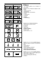
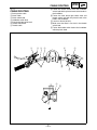
YFZ450W
YFZ450SEW
SUPPLEMENTARY
SERVICE MANUAL
LIT-11616-20-13
5TG-28197-12
FOREWORD
This Supplementary Service Manual has been prepared to introduce new service and data for the
YFZ450W/YFZ450SEW. For complete service information procedures it is necessary to use this
Supplementary Service Manual together with the following manual.
YFZ450S SERVICE MANUAL: LIT-11616-17-11 (5TG-28197-10)
YFZ450V SUPPLEMENTARY SERVICE MANUAL: LIT-11616-19-32 (5TG-28197-11)
YFZ450W/YFZ450SEW
SUPPLEMENTARY
SERVICE MANUAL
©2006 by Yamaha Motor Corporation, U.S.A.
First edition, April 2006
All rights reserved.
Any reproduction or unauthorized use
without the written permission of
Yamaha Motor Corporation, U.S.A.
is expressly prohibited.
Printed in U.S.A.
LIT-11616-20-13
EBS00002
NOTICE
This manual was produced by the Yamaha Motor Company primarily for use by Yamaha dealers
and their qualified mechanics. It is not possible to include all the knowledge of a mechanic in one
manual, so it is assumed that anyone who uses this book to perform maintenance and repairs on
Yamaha vehicle has a basic understanding of the mechanical ideas and the procedures of vehicle
repair. Repairs attempted by anyone without this knowledge are likely to render the vehicle unsafe
and unfit for use.
Yamaha Motor Company, Ltd. is continually striving to improve all its models. Modifications and significant changes in specifications or procedures will be forwarded to all authorized Yamaha dealers
and will appear in future editions of this manual where applicable.
NOTE:
Designs and specifications are subject to change without notice.
_
EBS00003
IMPORTANT INFORMATION
Particularly important information is distinguished in this manual by the following notations.
The Safety Alert Symbol means ATTENTION! BECOME ALERT! YOUR
SAFETY IS INVOLVED!
WARNING
CAUTION:
NOTE:
Failure to follow WARNING instructions could result in severe injury or death to
the vehicle operator, a bystander or a person checking or repairing the vehicle.
A CAUTION indicates special precautions that must be taken to avoid damage
to the vehicle.
A NOTE provides key information to make procedures easier or clearer.
EBS00004
HOW TO USE THIS MANUAL
MANUAL ORGANIZATION
This manual consists of chapters for the main categories of subjects. (See “symbols”)
1st title 1: This is the title of the chapter with its symbol in the upper right corner of each page.
2nd title 2: This title indicates the section of the chapter and only appears on the first page of each
section. It is located in the upper left corner of the page.
3rd title 3: This title indicates a sub-section that is followed by step-by-step procedures accompanied by corresponding illustrations.
EXPLODED DIAGRAMS
To help identify parts and clarify procedure steps, there are exploded diagrams at the start of each
removal and disassembly section.
1. An easy-to-see exploded diagram 4 is provided for removal and disassembly jobs.
2. Numbers 5 are given in the order of the jobs in the exploded diagram. A number that is enclosed
by a circle indicates a disassembly step.
3. An explanation of jobs and notes is presented in an easy-to-read way by the use of symbol marks
6. The meanings of the symbol marks are given on the next page.
4. A job instruction chart 7 accompanies the exploded diagram, providing the order of jobs, names
of parts, notes in jobs, etc.
5. For jobs requiring more information, the step-by-step format supplements 8 are given in addition
to the exploded diagram and the job instruction chart.
1
EBS00006
2
GEN
INFO
SYMBOLS
The following symbols are not relevant to
every vehicle.
Symbols 1 to 9 indicate the subject of each
chapter.
SPEC
3
4
CHK
ADJ
1 General information
2 Specifications
3 Periodic checks and adjustments
4 Engine
5 Cooling system
6 Carburetor
7 Chassis
8 Electrical
9 Troubleshooting
ENG
5
6
CARB
COOL
7
8
CHAS
ELEC
9
0
–
Symbols 0 to G indicate the following
0 Serviceable with engine mounted
A Filling fluid
B Lubricant
C Special tool
D Tightening torque
E Wear limit, clearance
F Engine speed
G Electrical data (Ω, V, A)
TRBL
SHTG
A
B
C
D
+
T.
R.
E
F
G
H
I
J
G
E
K
M
L
B
M
M
LS
N
Symbols H to M in the exploded diagrams
indicate the types of lubricants and lubrication
points.
O
LT
New
H Apply engine oil
I Apply gear oil
J Apply molybdenum disulfide oil
K Apply wheel bearing grease
L Apply lithium-soap-based grease
M Apply molybdenum disulfide grease
Symbols N to O in the exploded diagrams
indicate where to apply a locking agent N and
when to install a new part O.
N Apply the locking agent (LOCTITE®)
O Replace
CONTENTS
SPECIFICATIONS .............................................................................................. 1
GENERAL SPECIFICATIONS ..................................................................... 1
ENGINE SPECIFICATIONS......................................................................... 1
CHASSIS SPECIFICATIONS....................................................................... 2
TIGHTENING TORQUES............................................................................. 2
ENGINE TIGHTENING TORQUES ....................................................... 2
CABLE ROUTING ........................................................................................ 3
PERIODIC CHECKS AND ADJUSTMENTS...................................................... 9
INTRODUCTION .......................................................................................... 9
PERIODIC MAINTENANCE CHART FOR THE EMISSION CONTROL
SYSTEM ...................................................................................................... 9
GENERAL MAINTENANCE AND LUBRICATION CHART ........................ 10
CHASSIS.................................................................................................... 12
ADJUSTING THE FRONT SHOCK ABSORBERS
(for models equipped with two compression damping adjusters) ....... 12
ADJUSTING THE REAR SHOCK ABSORBER
(for models equipped with two compression damping adjusters) ....... 15
COOLING SYSTEM.......................................................................................... 20
WATER PUMP ........................................................................................... 20
CHECKING THE OIL NOZZLE ............................................................ 22
INSTALLING THE OIL NOZZLE .......................................................... 22
CHASSIS .......................................................................................................... 23
FRONT AND REAR BRAKES .................................................................... 23
FRONT BRAKE MASTER CYLINDER ................................................ 23
YFZ450W/YFZ450SEW 2007 WIRING DIAGRAM
GENERAL SPECIFICATIONS/
ENGINE SPECIFICATIONS
SPEC
EBS01001
SPECIFICATIONS
GENERAL SPECIFICATIONS
Item
Standard
Model code
5D31, 5D34
EBS01002
ENGINE SPECIFICATIONS
Item
Clutch
Friction plate 1 (inside dia.: 119 mm)
Thickness
Quantity
Friction plate 2 (inside dia.: 128 mm)
Thickness
Standard
2.92 ~ 3.08 mm (0.115 ~ 0.121 in)
7
2.92 ~ 3.08 mm (0.115 ~ 0.121 in)
1
Limit
2.8 mm
(0.110 in)
---2.8 mm
(0.110 in)
----
Quantity
Clutch plate
Thickness
Quantity
Max. warpage
1.5 ~ 1.7 mm (0.059 ~ 0.067 in)
7
----
------0.2 mm
(0.0079 in)
Clutch spring
Free length
47.8 mm (1.88 in)
Quantity
Clutch housing thrust clearance
Clutch housing radial clearance
Clutch release method
Push rod 2 bending limit
6
0.10 ~ 0.35 mm (0.0039 ~ 0.0138 in)
0.010 ~ 0.044 mm (0.0004 ~ 0.0017 in)
Inner push, cam push
0.1 mm (0.004 in)
46.0 mm
(1.81 in)
----------------
–1–
CHASSIS SPECIFICATIONS/
TIGHTENING TORQUES
SPEC
EBS01003
CHASSIS SPECIFICATIONS
Item
Rear disc brake
Type
Disc outside diameter × thickness
Pad thickness inner
Standard
Limit
Single
200.0 × 4.0 mm (7.87 × 0.16 in)
5.4 mm (0.21 in)
Pad thickness outer
5.4 mm (0.21 in)
Master cylinder inside diameter
Caliper cylinder inside diameter
Brake fluid type
12.7 mm (0.50 in)
25.4 mm (1.00 in)
DOT 4
------1.0 mm
(0.04 in)
1.0 mm
(0.04 in)
----------
EBS01005
TIGHTENING TORQUES
ENGINE TIGHTENING TORQUES
Part to be tightened
Oil gallery bolt
Part name
Thread
Q’ty
size
Bolt
–2–
M6
1
Tightening torque
Nm m · kg ft · lb
7
0.7
5.1
Remarks
CABLE ROUTING
È Fasten the clutch switch lead and handlebar
switch lead with the plastic bands at the bends in
the handlebar.
É Fasten the front brake light switch lead and
throttle switch lead with the plastic band at the
bend in the handlebar.
Ê Less than 20 mm (0.79 in)
Ë Make sure that there is no slack in the throttle
switch lead.
Ì Fasten the throttle switch lead to the handlebar
with the plastic band.
EBS00028
CABLE ROUTING
1 Parking brake cable
2 Clutch cable
3 Clutch switch lead
4 Handlebar switch lead
5 Front brake light switch lead
6 Throttle switch lead
7 Throttle cable
1
SPEC
2 3
4
5
È
É
6
A
7
Ê
Ì
A
–3–
6
Ë
CABLE ROUTING
1 Indicator coupler
2 Radiator fan motor coupler
3 Thermo switch 2
4 Fuel tank breather hose
5 Radiator fan motor lead
6 Radiator fan breather hose
7 Wire harness
8 Fuel hose
9 Throttle position sensor lead
0 Carburetor switch lead
A Crankcase breather hose
B Negative battery lead
C Starter motor lead
D Neutral switch lead
E A.C. magneto lead
F Oil tank breather hose
G Resistor lead
H Headlight relay 1
I Headlight relay 2
J A.C. magneto coupler
K Neutral switch coupler
L Front brake hose
M Throttle cable
N Parking brake cable
O Clutch cable
P Indicator leads
Q Cylinder head breather hose
Û L
7
P
Ü
M
7
B-B
Ý
C-C
A
A
0
D-D
Ë
O
2
5
4
N
Þ
SPEC
3É
1
È
Î
C
56
7
B
Ì
Ê
B
K
J
G
G
C
Í
G
D
89
E
9
Ï 0
Ð
D
G
Ñ
E
H
ÚI
ÚH
G
A
B
C
Ò
F
F
Ù Ø
× F
Ö E
À
G
D
E
Á
H
Õ Ô DÓ
ß
E
D
G-G
Q
F-F
–4–
E-E
CABLE ROUTING
Ê 7 ~ 21 mm (0.28 ~ 0.83 in)
Ë 57 ~ 77 mm (2.24 ~ 3.03 in)
Ì Fasten the wire harness, throttle position sensor
lead, and carburetor switch lead with the plastic
band. Make sure that there is no slack in the
throttle position sensor lead and carburetor
switch lead along the frame as shown.
Í More than 15 mm (0.59 in)
Î Install the cylinder head breather hose with the
paint mark facing to the left.
È Connect the neutral switch coupler and the A.C.
magneto coupler, and then fasten the leads with
the plastic band, making sure that they are
routed under the frame and that they do not contact headlight relay 2.
É Fasten the wire harness, thermo switch 2 lead,
A.C. magneto lead, resistor lead, neutral switch
lead, and radiator fan motor lead with the plastic
band and then face the end of the band inward
between the frame tubes.
Û L
7
P
Ü
M
7
B-B
Ý
C-C
A
A
0
D-D
Ë
O
2
5
4
N
Þ
SPEC
3É
1
È
Î
C
56
7
B
Ì
Ê
B
K
J
G
G
C
Í
G
D
89
E
9
Ï 0
Ð
D
G
Ñ
E
H
ÚI
ÚH
G
A
B
C
Ò
F
F
Ù Ø
× F
Ö E
À
G
D
E
Á
H
Õ Ô DÓ
ß
E
D
G-G
Q
F-F
–5–
E-E
CABLE ROUTING
Ñ Fasten the starter motor lead to the negative
battery lead at the mark on the battery lead with
the plastic band. Then, fasten the starter motor
lead and negative battery lead to the frame with
the plastic band and face the end of the band
inward.
Ò Install the crankcase breather hose with the
paint mark facing to the left.
Ó Route the neutral switch lead so that it does not
contact the edges of the joint on the end of the
oil pipe 2.
Ï Fasten the wire harness with the plastic band on
the positioning tape and then face the end of the
plastic band inward.
Ð Fasten the negative battery lead and starter
motor lead with the plastic band and then face
the end of the plastic band inward.
Û L
7
P
Ü
M
7
B-B
Ý
C-C
A
A
0
D-D
Ë
O
2
5
4
N
Þ
SPEC
3É
1
È
Î
C
56
7
B
Ì
Ê
B
K
J
G
G
C
Í
G
D
89
E
9
Ï 0
Ð
D
G
Ñ
E
H
ÚI
ÚH
G
A
B
C
Ò
F
F
Ù Ø
× F
Ö E
À
G
D
E
Á
H
Õ Ô DÓ
ß
E
D
G-G
Q
F-F
–6–
E-E
CABLE ROUTING
Ù Wrap the resistor lead around the frame as
shown in the illustration, and then fasten it with
the plastic band. Face the end of the plastic
band inward.
Ú Install headlight relay 1 and headlight relay 2 to
the inside of the frame, making sure to insert the
tab on each relay completely into its rubber
holder and to install the holders all the way onto
the tabs on the stay.
Ô Fasten the neutral switch lead with the lead
holder.
Õ Fasten the neutral switch lead with the clamp.
Ö Fasten the A.C. magneto lead with the lead
holder.
× Fasten the neutral switch lead and A.C. magneto lead with the plastic band. Face the end of
the plastic band inward on top of the frame.
Ø Pass the neutral switch lead and A.C. magneto
lead through the guide on the fender stay.
Û L
7
P
Ü
M
7
B-B
Ý
C-C
A
A
0
D-D
Ë
O
2
5
4
N
Þ
SPEC
3É
1
È
Î
C
56
7
B
Ì
Ê
B
K
J
G
G
C
Í
G
D
89
E
9
Ï 0
Ð
D
G
Ñ
E
H
ÚI
ÚH
G
A
B
C
Ò
F
F
Ù Ø
× F
Ö E
À
G
D
E
Á
H
Õ Ô DÓ
ß
E
D
G-G
Q
F-F
–7–
E-E
CABLE ROUTING
ß Fasten the cylinder head breather hose with the
holder, making sure that the catch of the holder
is facing upward.
À Fasten the A.C. magneto lead and neutral
switch lead with the plastic band, making sure
that the end of the band is on top of the frame,
facing inward.
Á Fasten the resistor lead with the holders.
Û When installing the fuel tank cover, do not pinch
the front brake hose, throttle cable, front brake
light switch lead, and throttle switch lead.
Ü Route the front brake hose in front of the handlebar cover.
Ý Route the clutch cable and parking brake cable
in front of the handlebar cover.
Þ When installing the fuel tank cover, do not pinch
the clutch cable, parking brake cable, clutch
switch lead, and handlebar switch lead.
Û L
7
P
Ü
M
7
B-B
Ý
C-C
A
A
0
D-D
Ë
O
2
5
4
N
Þ
SPEC
3É
1
È
Î
C
56
7
B
Ì
Ê
B
K
J
G
G
C
Í
G
D
89
E
9
Ï 0
Ð
D
G
Ñ
E
H
ÚI
ÚH
G
A
B
C
Ò
F
F
Ù Ø
× F
Ö E
À
G
D
E
Á
H
Õ Ô DÓ
ß
E
D
G-G
Q
F-F
–8–
E-E
INTRODUCTION/PERIODIC MAINTENANCE CHART
FOR THE EMISSION CONTROL SYSTEM
CHK
ADJ
EBS00029
PERIODIC CHECKS AND ADJUSTMENTS
INTRODUCTION
This chapter includes all information necessary to perform recommended checks and adjustments.
These preventive maintenance procedures, if followed, will ensure more reliable vehicle operation
and a longer service life. The need for costly overhaul work will be greatly reduced. This information
applies to vehicles already in service as well as to new vehicles that are being prepared for sale. All
service technicians should be familiar with this entire chapter.
PERIODIC MAINTENANCE CHART FOR THE EMISSION CONTROL
SYSTEM
NOTE:
• For ATVs not equipped with an odometer or an hour meter, follow the month maintenance intervals.
• For ATVs equipped with an odometer or an hour meter, follow the km (mi) or hours maintenance
intervals. However, keep in mind that if the ATV isn’t used for a long period of time, the month
maintenance intervals should be followed.
• Items marked with an asterisk should be performed by a Yamaha dealer as they require special
tools, data and technical skills.
INITIAL
NO.
ITEM
CHECK OR MAINTENANCE JOB
Whichever
comes first
EVERY
month
1
3
6
6
12
km
(mi)
320
(200)
1300
(800)
2500
(1600)
2500
(1600)
5000
(3200)
hours
20
80
160
160
320
√
√
√
√
√
√
√
√
√
√
√
√
1 *
Fuel line
• Check fuel hoses for cracks or other damage, and
replace if necessary.
2
Spark plug
• Check condition and clean, regap, or replace if necessary.
√
3 *
Valves
• Check valve clearance and adjust if necessary.
√
4 *
Carburetor
• Check starter (choke) operation and correct if necessary.
• Check engine idling speed and adjust if necessary.
5 *
Crankcase breather
system
• Check breather hose for cracks or other damage,
and replace if necessary.
√
√
√
6 *
Exhaust system
• Check for leakage and replace gasket(s) if necessary.
• Check for looseness and tighten all screw clamps
and joints if necessary.
√
√
√
7
Spark arrester
• Clean.
√
√
√
–9–
√
√
CHK
ADJ
GENERAL MAINTENANCE AND LUBRICATION CHART
GENERAL MAINTENANCE AND LUBRICATION CHART
INITIAL
NO.
ITEM
CHECK OR MAINTENANCE JOB
Whichever
comes first
1
3
6
6
12
km
(mi)
320
(200)
1300
(800)
2500
(1600)
2500
(1600)
5000
(3200)
hours
20
80
160
160
320
Every 20–40 hours (more often in wet or
dusty areas)
1
Air filter element
• Clean and replace if necessary.
2 *
Clutch
• Check operation and adjust if necessary.
√
Front brake
• Check operation and correct if necessary.
• Check fluid level and ATV for fluid leakage, and correct if necessary.
√
3 *
Rear brake
√
√
√
√
√
√
√
Whenever worn to the limit
• Replace brake pads.
4 *
EVERY
month
• Check operation and correct if necessary.
• Check brake lever free play and adjust if necessary.
• Check fluid level and ATV for fluid leakage, and correct if necessary.
√
√
√
√
√
Whenever worn to the limit
• Replace brake pads.
5 *
Brake hoses
• Check for cracks or other damage, and replace if
necessary.
6 *
Parking brake
• Check operation and adjust if necessary.
√
7 *
Wheels
• Check runout and for damage, and replace if necessary.
8 *
√
√
√
√
√
√
√
√
√
√
√
Tires
• Check tread depth and for damage, and replace if
necessary.
• Check air pressure and balance, and correct if necessary.
√
√
√
√
9 *
Wheel bearings
• Check for looseness or damage, and replace if necessary.
√
√
√
√
10 *
Swingarm pivots
• Check operation and for excessive play, and replace
bearings if necessary.
• Lubricate with molybdenum disulfide grease.
√
√
√
11 *
Upper and lower arm
• Lubricate with lithium-soap-based grease.
pivots
√
√
√
12
Drive chain
√
√
√
13 *
Drive chain rollers
• Check for wear and replace if necessary.
√
√
√
14 *
Chassis fasteners
• Make sure that all nuts, bolts, and screws are properly tightened.
√
√
√
15 *
Shock absorber
assemblies
• Check operation and correct if necessary.
• Check for oil leakage and replace if necessary.
√
√
√
16 *
Rear suspension
relay arm and con• Check operation and correct if necessary.
necting arm pivoting • Lubricate with lithium-soap-based grease.
points
√
√
√
17 *
Steering shaft
• Lubricate with lithium-soap-based grease.
√
√
√
18 *
Steering system
• Check operation and repair or replace if damaged.
• Check toe-in and adjust if necessary.
√
√
√
19 *
Engine mount
• Check for cracks or other damage, and replace if
necessary.
√
√
√
20
Engine oil
• Change.
• Check ATV for oil leakage, and correct if necessary.
√
√
√
√
21
Engine oil filter element
• Clean or replace if necessary.
√
√
Every 4 years
• Replace.
• Check chain slack and adjust if necessary.
• Check rear wheel alignment and correct if necesssary.
• Clean and lubricate.
– 10 –
√
√
√
√
√
√
√
√
√
CHK
ADJ
GENERAL MAINTENANCE AND LUBRICATION CHART
INITIAL
NO.
22
ITEM
Cooling system
CHECK OR MAINTENANCE JOB
Whichever
comes first
EVERY
month
1
3
6
6
12
km
(mi)
320
(200)
1300
(800)
2500
(1600)
2500
(1600)
5000
(3200)
hours
20
80
160
160
320
√
√
√
√
√
• Check coolant level and ATV for coolant leakage,
and correct if necessary.
• Replace coolant.
Every 2 years
23 *
Moving parts and
cables
• Lubricate.
24 *
Throttle lever housing and cable
• Check operation and correct if necessary.
• Check throttle cable free play and adjust if necessary.
• Lubricate throttle lever housing and cable.
25 *
Front and rear brake
switches
26 *
Lights and switches
√
√
√
√
√
√
√
√
√
• Check operation and correct if necessary.
√
√
√
√
√
• Check operation and correct if necessary.
• Adjust headlight beams.
√
√
√
√
√
NOTE:
• The air filter needs more frequent service if you are riding in unusually wet or dusty areas.
• Hydraulic brake service
• Regularly check and, if necessary, correct the brake fluid level.
• Every two years replace the internal components of the brake master cylinders and calipers, and
change the brake fluid.
• Replace the brake hoses every four years and if cracked or damaged.
– 11 –
ADJUSTING THE FRONT SHOCK ABSORBERS (for models equipped
with two compression damping adjusters)
CHK
ADJ
CHASSIS
EBS00111
ADJUSTING THE FRONT SHOCK
ABSORBERS (for models equipped with
two compression damping adjusters)
WARNING
_
1
2
a
Always adjust the spring preload, rebound
damping force and compression damping
force of both front shock absorbers to the
same setting. Uneven adjustment can
result in poor handling and loss of stability.
1. Adjust:
• spring preload
▼▼▼▼▼▼▼▼▼▼▼▼▼▼▼▼▼▼▼▼▼▼▼▼▼▼▼▼▼▼▼▼
a. Elevate the front wheels by placing a suitable stand under the frame.
b. Loosen the locknut 1.
c. Turn the adjusting ring 2 in direction a or
b.
b
Direction a
Spring preload is
increased (suspension
is harder).
Direction b
Spring preload is
decreased (suspension
is softer).
c
Adjusting length c
Standard: 255 mm (10.0 in)
Minimum: 246.5 mm (9.7 in)
Maximum: 261.5 mm (10.3 in)
NOTE:
• Be sure to remove all dirt and mud from
around the locknut and adjusting ring before
adjustment.
• The length of the spring (installed) changes
1.5 mm (0.06 in) per turn of the adjuster.
_
CAUTION:
_
Never attempt to turn the adjusting ring
beyond the maximum or minimum setting.
– 12 –
ADJUSTING THE FRONT SHOCK ABSORBERS (for models equipped
with two compression damping adjusters)
CHK
ADJ
d. Tighten the locknut 1 with a steering nut
wrench 3.
NOTE:
Set the torque wrench at a right angle to the
steering nut wrench.
Steering nut wrench
P/N. YU-33975, 90890-01443
T.
Locknut
30 Nm (3.0 m · kg, 22 ft · lb)
R.
NOTE:
Always tighten the locknut against the adjusting ring, then torque it to specification.
_
▲▲▲▲▲▲▲▲▲▲▲▲▲▲▲▲▲▲▲▲▲▲▲▲▲▲▲▲▲▲▲▲
2. Adjust:
• rebound damping force
▼▼▼▼▼▼▼▼▼▼▼▼▼▼▼▼▼▼▼▼▼▼▼▼▼▼▼▼▼▼▼▼
a. Turn the adjusting screw 1 in direction a
or b.
Direction a
Rebound damping force
is increased.
Direction b
Rebound damping force
is decreased.
From the fully turned-in position
Standard: 10 clicks out
Minimum: 20 clicks out
Maximum: 1 click out
NOTE:
Make sure that the position indicator marks c
are aligned when the shock absorber is set to
the standard setting.
CAUTION:
_
Do not force the adjuster past the minimum
or maximum extent of adjustment. The
adjuster may be damaged.
▲▲▲▲▲▲▲▲▲▲▲▲▲▲▲▲▲▲▲▲▲▲▲▲▲▲▲▲▲▲▲▲
– 13 –
ADJUSTING THE FRONT SHOCK ABSORBERS (for models equipped
with two compression damping adjusters)
CHK
ADJ
3. Adjust:
• compression damping force (fast compression damping)
▼▼▼▼▼▼▼▼▼▼▼▼▼▼▼▼▼▼▼▼▼▼▼▼▼▼▼▼▼▼▼▼
a. Turn the adjusting bolt 1 in direction a or
b.
Direction a
Compression damping
force is increased.
Direction b
Compression damping
force is decreased.
Standard: Adjusting bolt 1 turn out from
the fully turned in position
Minimum (soft): Adjusting bolt 3 turns
out from the fully turned in position
Maximum (hard): Adjusting bolt fully
turned in
NOTE:
Make sure that the position indicator marks c
are aligned when the shock absorber is set to
the standard setting.
_
CAUTION:
Do not force the adjuster past the minimum
or maximum extent of adjustment. The
adjuster may be damaged.
▲▲▲▲▲▲▲▲▲▲▲▲▲▲▲▲▲▲▲▲▲▲▲▲▲▲▲▲▲▲▲▲
– 14 –
ADJUSTING THE FRONT SHOCK ABSORBERS (for models equipped with two
compression damping adjusters)/ADJUSTING THE REAR SHOCK ABSORBER
(for models equipped with two compression damping adjusters)
CHK
ADJ
4. Adjust:
• compression damping force (slow compression damping)
▼▼▼▼▼▼▼▼▼▼▼▼▼▼▼▼▼▼▼▼▼▼▼▼▼▼▼▼▼▼▼▼
a. Turn the adjusting screw 1 in direction a
or b.
Direction a
Compression damping
force is increased.
Direction b
Compression damping
force is decreased.
From the fully turned-in position
Standard: 10 clicks out
Minimum: 20 clicks out
Maximum: 1 click out
NOTE:
Make sure that the position indicator marks c
are aligned when the shock absorber is set to
the standard setting.
_
CAUTION:
Do not force the adjuster past the minimum
or maximum extent of adjustment. The
adjuster may be damaged.
▲▲▲▲▲▲▲▲▲▲▲▲▲▲▲▲▲▲▲▲▲▲▲▲▲▲▲▲▲▲▲▲
EBS00111
ADJUSTING THE REAR SHOCK
ABSORBER (for models equipped with two
compression damping adjusters)
1. Remove:
• seat
Refer to “SEAT, FENDERS AND FUEL
TANK” in chapter 3.
(Manual No.: 5TG-28197-10)
2. Loosen the clamp screw 1, and then disconnect the air intake duct.
1
– 15 –
ADJUSTING THE REAR SHOCK ABSORBER (for models equipped with
two compression damping adjusters)
CHK
ADJ
3. Disconnect the air filter case breather hose
1, and then remove the air filter case 2
with the air intake duct.
2
1
1
2
a
b
4. Adjust:
• spring preload
▼▼▼▼▼▼▼▼▼▼▼▼▼▼▼▼▼▼▼▼▼▼▼▼▼▼▼▼▼▼▼▼
a. Elevate the rear wheels by placing a suitable stand under the frame.
b. Loosen the locknut 1.
c. Turn the adjusting ring 2 in direction a or
b.
Direction a
Spring preload is
increased (suspension
is harder).
Direction b
Spring preload is
decreased (suspension
is softer).
Adjusting length c
Standard: 257 mm (10.1 in)
Minimum: 250 mm (9.8 in)
Maximum: 264 mm (10.4 in)
c
NOTE:
• Be sure to remove all dirt and mud from
around the locknut and adjusting ring before
adjustment.
• The length of the spring (installed) changes
1.5 mm (0.06 in) per turn of the adjuster.
_
CAUTION:
_
Never attempt to turn the adjusting ring
beyond the maximum or minimum setting.
d. Tighten the locknut 1 with a steering nut
wrench 3.
NOTE:
Set the torque wrench at a right angle to the
steering nut wrench.
– 16 –
ADJUSTING THE REAR SHOCK ABSORBER (for models equipped with
two compression damping adjusters)
CHK
ADJ
Steering nut wrench
P/N. YU-33975, 90890-01443
T.
Locknut
44 Nm (4.4 m · kg, 32 ft · lb)
R.
NOTE:
Always tighten the locknut against the adjusting ring, then torque it to specification.
_
▲▲▲▲▲▲▲▲▲▲▲▲▲▲▲▲▲▲▲▲▲▲▲▲▲▲▲▲▲▲▲▲
b
a
5. Install:
• air filter case with air intake duct
NOTE:
Align the projection a on the carburetor with
the slot b in the air intake duct.
_
6. Adjust:
• rebound damping force
1
c
b
▼▼▼▼▼▼▼▼▼▼▼▼▼▼▼▼▼▼▼▼▼▼▼▼▼▼▼▼▼▼▼▼
a
1
a. Turn the adjusting screw 1 in direction a
or b.
Direction a
Rebound damping force
is increased.
Direction b
Rebound damping force
is decreased.
Standard: Adjusting screw 1 1/2 turns
out from the fully turned in position
Minimum (soft): Adjusting screw 3 turns
out from the fully turned in position
Maximum (hard): Adjusting screw fully
turned in
NOTE:
Make sure that the position indicator marks c
are aligned when the shock absorber is set to
the standard setting.
CAUTION:
_
Do not force the adjuster past the minimum
or maximum extent of adjustment. The
adjuster may be damaged.
▲▲▲▲▲▲▲▲▲▲▲▲▲▲▲▲▲▲▲▲▲▲▲▲▲▲▲▲▲▲▲▲
– 17 –
ADJUSTING THE REAR SHOCK ABSORBER (for models equipped with
two compression damping adjusters)
CHK
ADJ
7. Adjust:
• compression damping force (fast compression damping)
a
▼▼▼▼▼▼▼▼▼▼▼▼▼▼▼▼▼▼▼▼▼▼▼▼▼▼▼▼▼▼▼▼
1
b
a. Turn the adjusting bolt 1 in direction a or
b.
1
c
Direction a
Compression damping
force is increased.
Direction b
Compression damping
force is decreased.
Standard: Adjusting bolt 2 turns out from
the fully turned in position
Minimum (soft): Adjusting bolt 3 turns
out from the fully turned in position
Maximum (hard): Adjusting bolt fully
turned in
NOTE:
Make sure that the position indicator marks c
are aligned when the shock absorber is set to
the standard setting.
CAUTION:
_
Do not force the adjuster past the minimum
or maximum extent of adjustment. The
adjuster may be damaged.
▲▲▲▲▲▲▲▲▲▲▲▲▲▲▲▲▲▲▲▲▲▲▲▲▲▲▲▲▲▲▲▲
– 18 –
ADJUSTING THE REAR SHOCK ABSORBER (for models equipped with
two compression damping adjusters)
CHK
ADJ
8. Adjust:
• compression damping force (slow compression damping)
a
▼▼▼▼▼▼▼▼▼▼▼▼▼▼▼▼▼▼▼▼▼▼▼▼▼▼▼▼▼▼▼▼
1
b
a. Turn the adjusting screw 1 in direction a
or b.
1
c
Direction a
Compression damping
force is increased.
Direction b
Compression damping
force is decreased.
From the fully turned-in position
Standard: 11 clicks out
Minimum: 20 clicks out
Maximum: 1 click out
NOTE:
Make sure that the position indicator marks c
are aligned when the shock absorber is set to
the standard setting.
CAUTION:
_
Do not force the adjuster past the minimum
or maximum extent of adjustment. The
adjuster may be damaged.
▲▲▲▲▲▲▲▲▲▲▲▲▲▲▲▲▲▲▲▲▲▲▲▲▲▲▲▲▲▲▲▲
9. Install:
• seat
Refer to “SEAT, FENDERS AND FUEL
TANK” in chapter 3.
(Manual No.: 5TG-28197-10)
– 19 –
WATER PUMP
COOL
EBS00134
COOLING SYSTEM
WATER PUMP
Order
Job/Part
Removing the water pump
Engine oil
Coolant
Exhaust pipe
Q’ty
Rear brake light switch/footrest (right)
Clutch cover
1
2
3
4
5
6
Radiator outlet hose
Water pump inlet pipe
Water pump housing
Oil filter element cover
Oil filter element
Parking brake holder
1
1
1
1
1
1
– 20 –
Remarks
Remove the parts in the order listed.
Drain.
Drain.
Refer to “ENGINE REMOVAL”.
(Manual No.: 5TG-28197-11)
Refer to “FRONT AND REAR BRAKES”.
(Manual No.: 5TG-28197-11)
Refer to “CLUTCH” in chapter 4.
(Manual No.: 5TG-28197-10)
WATER PUMP
Order
7
8
9
10
11
12
13
14
15
16
17
18
Job/Part
Oil delivery pipe 1
Oil pipe 1
Water pump breather hose
Right crankcase cover
Gasket
Oil nozzle
Impeller
Washer
Impeller shaft
Oil seal
Bearing
Oil seal
COOL
Q’ty
Remarks
1
1
1
1
1
1
Refer to “INSTALLING THE OIL NOZZLE”.
1
1
1
1
1
1
For installation, reverse the removal procedure.
– 21 –
WATER PUMP
COOL
CHECKING THE OIL NOZZLE
1. Check:
• oil nozzle
Damage/wear → Replace the oil nozzle.
• oil passage
Obstruction → Blow out with compressed
air.
INSTALLING THE OIL NOZZLE
1. Install:
• O-ring 1
• oil nozzle 2
2
NOTE:
Be sure to fit the projection on the oil nozzle
into the groove in the right crankcase cover.
1
– 22 –
FRONT AND REAR BRAKES
CHAS
EBS00407
CHASSIS
FRONT AND REAR BRAKES
FRONT BRAKE MASTER CYLINDER
Order
1
2
3
4
5
6
7
8
9
10
Job/Part
Removing the front brake master
cylinder
Brake fluid
Brake fluid reservoir cap
Brake fluid reservoir diaphragm
Front brake light switch connector
Front brake light switch
Brake lever
Union bolt
Copper washer
Brake hose
Brake master cylinder bracket
Brake master cylinder
Q’ty
Remarks
Remove the parts in the order listed.
Drain.
1
1
2
1
1
1
2
1
1
1
Disconnect.
Disconnect.
Refer to “INSTALLING
THE FRONT BRAKE
MASTER CYLINDER” in
chapter 7. (Manual No.:
5TG-28197-10)
For installation, reverse the removal procedure.
– 23 –
YFZ450W/YFZ450SEW 2007 WIRING DIAGRAM
1 A.C. magneto
2 Rectifier/regulator
3 Main switch
4 Battery
5 Fuse
6 Starter relay
7 Starter motor
8 Diode 1
9 Starting circuit cut-off relay
0 Clutch switch
A C.D.I. unit
B Ignition coil
C Spark plug
D Throttle position sensor
E Throttle switch
F Carburetor switch
G Circuit breaker (fan motor)
H Thermo switch 1
I Fan motor
J Coolant temperature warning
light
K Neutral indicator light
L Neutral switch
M Diode 2
N Thermo switch 2
O Handlebar switch
P Light switch
Q Engine stop switch
R Start switch
S Headlight
T Headlight relay 1
U Headlight relay 2
V Resistor
W Tail/brake light
X Rear brake light switch
Y Front brake light switch
COLOR CODE
B ........... Black
Br .......... Brown
G ........... Green
L ............ Blue
O ........... Orange
R ........... Red
Sb ......... Sky blue
W .......... White
Y ........... Yellow
B/L ........ Black/Blue
B/Y ........ Black/Yellow
Br/L ....... Brown/Blue
G/R ....... Green/Red
L/B ........ Blue/Black
R/B ........ Red/Black
R/W ....... Red/White
W/B ....... White/Black
W/L ....... White/Blue
Y/B ........ Yellow/Black
Y/L ........ Yellow/Blue
Y/R ........ Yellow/Red
Y/W ....... Yellow/White
YAMAHA MOTOR CO., LTD.
2500 SHINGAI IWATA SHIZUOKA JAPAN
PRINTED IN U.S.A.
YFZ450W/YFZ450SEW 2007 WIRING DIAGRAM
W
R
R W
W R
(BLACK)
(BLACK)
Y/R W/B
W Y
1
W/B
Y/R
W/B
Y/R
R
2
R
R
B/Y Y L R
B/L R/B
Sb
O W
B W/B
(BLACK)
(BLACK)
R
B W
W/B B
Y
R Y/R
R
R
O B
R
4
15A
(BLACK)
B
B
5
R R
Y/B L/B
W/B
W
R
O
C
6
L/B
A
R/B
B/Y
Y/B B/Y
B
B
B
B/Y Y/B
Sb R/B
7
0
(BLACK)
Y/B
L
Y
B/L
B/Y
Sb
9
R/B
R
L
Y
B/L
3
Sb
(GRAY)
Y/B
L/B
Br
Br/L
(BLACK)
Br/L
B/Y
Br
O
Br
Br
R/B
L/B
L/B
X
M
R/B L
L R/B
Y
R/B
B B
L/B Br
Br R/W
Y/W
G Y
P
OFF
LO
HI
(BLACK)
Y
Q
R
OFF
RUN
L/B
OFF
PUSH
L Y/W
Sb
Br Sb
R/B W/L
B
(BLACK)
Y L
B
Y/R
Y
G/R
G/R
B
L
Y
B
Y/L
L
B/L B/Y
(GRAY)
(GRAY)
Y
G/R
Y
Y/W G B
(BLACK)
V
B
B
B Y/L
S
S
Y G
Y G
B
B
(BLACK)
(BLACK)
B
B
L
Y G
Sb
Y/L
(BLACK)
L
Sb
B
Y G
Y/R
G/R
L Y/L B
R/W L
(BLACK)
(BROWN)
G
Y/W
B
B
H
I
L
B
G Y
B
G Y
B
(BLACK)
(BLACK)
L
B
B
L
Sb
B
B/L
B/L B/Y
R/W
W/L B
T
U
W
B/Y B
(GRAY)
W/L
N
L
B/Y B
B/L
R/W
W/L
E
(GRAY)
Sb Br
W/L Br
Y Br
Y
G
J K
W/L
B
B
B/Y
F
Br
W/L
(GRAY)
B/L
B
R Br
R Br/L
L/B
Y
B
Y L
8
Br R/W
Br/L R
L
D
B
OFF
ON
B
B
Y/B
B
R
O