1
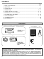
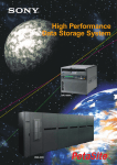
ID PHOTO SYSTEM
DIS710E
OPERATION MANUAL
MONITOR
ALARM
SHEET
PAPER
MEMORY
PRINT
S-VIDEO
POWER
OPEN
REMOTE
CONTENTS
Page
1
SAFETY PRECAUTIONS ......................................................................................... 3 - 5
2
UNPACKING ................................................................................................................... 6
3
PRINTER SETUP ..................................................................................................... 7 - 9
4
CONNECTION ....................................................................................................... 10 - 11
5
TAKING THE FIRST PICTURE ............................................................................. 12 - 13
6
PICTURE QUALITY ADJUSTMENT ..................................................................... 14 - 16
7
FEATURES AND FUNCTIONS ............................................................................. 17 - 18
8
ADVANCED SETTING .......................................................................................... 19 - 21
9
TROUBLESHOOTING .................................................................................................. 22
10 SPECIFICATIONS ........................................................................................................ 23
CONTENTS
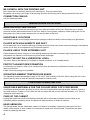
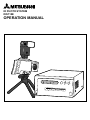
This system is composed by the following components.
Printer
Options
(not provided from Mitsubishi)
MONITOR
ALARM
SHEET
PAPER
MEMORY
PRINT
S-VIDEO
POWER
OPEN
REMOTE
• AC cable
• Operation manual
• Ink cassette
Printer
System
Camera
Connection box
Monitor
• System cable
• Operation manual
• 3 guide sheets
• Print paper and ink
sheet
Tripod
Strobe
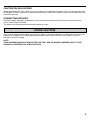
This system complies with the requirements of the EC Directive 89/336/EEC "EMC Directive"
as amended by Directive 93/68/EEC.
The electro-magnetic susceptibility has been chosen at a level that gains proper operation in
residential areas, on business and light industrial premises and on small-scale enterprises,
inside as well as outside of the buildings. All places of operation are characterised by their
connection to the public low voltage power supply system.
2
1. SAFETY PRECAUTIONS
In the interest of safety, please observe the following precautions:
POWER REQUIREMENT
This system is designed for operation on 220V-240V, 50Hz AC. Never connect to any outlet or power supply
having a different voltage or frequency.
WARNNG: THIS APPARATUS MUST BE EARTHED.
AVERTISSEMENT: CET APPAREIL DOIT ETRE MIS A LA TERRE.
PROTECTIVE MEASURES
IF ABNORMAL OPERATIONS OCCUR, .....
Use of the unit during emission of smoke or abnormal sounds (without adopting countermeasures) is
dangerous. In such a case, unplug the power cord from the source outlet immediately, and request
maintenance service from the sales dealer.
NEVER INSERT ANY OBJECT INTO THE UNIT
Foreign objects of an kind inserted into this unit constitutes a safety hazard and can cause extensive
damage.
DO NOT PLACE ANYTHING ON THE COLOUR VIDEO COPY PROCESSOR
Heavy objects placed on the Colour Video Copy Processor can cause damage or obstruct proper ventilation.
PROTECT THE POWER CORD
Damage to the power cord may cause fire or shock hazard. When unplugging, hold by the plug only and
remove carefully.
DO NOT PLACE WATER CONTAINERS ON THE UNIT
Do not place flower vases, and other water-holding containers on the device. If, for some reason, water
seeps to the inside of the unit, unplug the power cord from the source outlet, and contact the sales dealer. If
used without corrective measures, the unit may be damaged.
"In the interest of safety, avoid handling of liquids near the unit."
DO NOT REMOVE THE CABINET
Touching internal parts is dangerous, and could lead to malfunction. Contact the sales dealer to carry
out internal checks and adjustments. Before opening the cover for eliminating jammed paper, etc., be sure
to disconnect the power cord plug.
UNPLUG THE POWER CORD DURING A LONG ABSENCE
Turn off the MAIN power switch and unplug the power cord during a long absence.
WHEN TRANSPORTING THE UNIT
When transporting the unit, remove the sheet cartridge and paper from the paper cassette, and insert the
protective cushion into its compartment. Make sure to replace the printer's transit screw.
BE CAREFUL AROUND PRINT PAPER EXIT SLOT
Don't insert your hand or any material into the paper exit slot during printing.
Don't touch the cutter blade inside the paper exit slot.
Otherwise, your finger will be injured.
DO NOT TOUCH THE THERMAL HEAD
Do not touch the thermal head (located inside the unit).
The thermal head is heated to high temperature, and may cause injury.
3
BE CAREFUL WITH THE PRINTING UNIT
Don't move the unit while the printing unit is sliding out. This may cause injury.
Be careful not to catch your finger in the printing unit while the printing unit is being retracted into the unit.
CONNECTION CABLES
Use the cables provided
INSTALLATION LOCATIONS
MAINTAIN GOOD VENTILATION
Ventilation slots and holes are provided on the top, sides and bottom of this unit. Place the unit on a hard
and level surface and locate at least 10 cm from walls to insure proper ventilation. When putting the unit on
the system rack, take a space between the unit and the back of the rack.
UNSUITABLE LOCATIONS
Avoid shaky places or hot-springs areas where hydrogen sulfide and acidic ions are likely to be generated.
PLACES WITH HIGH HUMIDITY AND DUST
Do not place the unit in locations with high humidity and dust, which can cause extensive damage. Avoid places
where unit is likely to be exposed to oily fumes and vapours.
PLACES LIKELY TO BE EXTREMELY HOT
Places exposed to direct sunlight, or near heating appliances can attain extremely high temperatures, which
may deform the cabinet, or can become a prime cause of damage.
PLACE THE UNIT ON A HORIZONTAL LEVEL
The unit is likely to be affected if it is placed in slanted conditions or in unstable places.
PROTECT AGAINST DEW FORMATION
In extremely cold regions, if the unit is moved quickly from an extremely cold place to warmer one, dew is
likely to be formed.
If dew is formed, printing is not possible.
OPERATING AMBIENT TEMPERATURE RANGE
The operating ambient temperature range is 5°C- 40°C, and humidity of 20-80%. When using the unit on the
system rack, be sure to keep this ambient temperature inside the rack.
FOR LONG OPERATING LIFE
UNSUITABLE MATERIALS FOR THE COLOUR VIDEO COPY PROCESSOR
Coat flaking and deformation are likely to occur if the unit is wiped with chemical dusters, benzine, thinner or
any other solvent, if rubber or PVC items are left in contact with the unit for extended duration, or if the unit
is sprayed with insecticide.
CARE OF THE CABINET
Unplug and clean with a soft cloth slightly moistened with a mild soap and water solution. Allow to dry
completely before operating. Never use petroleum base solutions or abrasive cleaners.
HEAD ABRASION
The thermal head, like the video head, wears out. When it is abraded, it becomes hard to print out fine
details of the picture. In such a case, it is necessary to replace the thermal head. Consult with the sales
dealer for replacing the head.
4
CAUTION ON RELOCATING
When transporting this unit, make sure it is not likely to be subjected to impacts. They can be a prime cause
for damage. Further, make sure to disconnect the power cord from the power outlet, and the cables from the
connected devices.
CONNECTING DEVICES
Read thoroughly "Operating Precautions" of the instruction booklets for the devices connected with the
Colour Video Copy Processor.
The power cord must be disconnected after printing is over.
OTHER CAUTIONS
Dust or other foreign matter adhering to the print paper or the sheet cartridge, or deformation resulting from
exposure to extremely low or high temperatures could cause loss of colour, uneven colour or lines, or
wrinkles in the print images.
NOTE:
YOUR UNDERSTANDING IS REQUESTED FOR THE LOSS OF IMAGES IN MEMORY DUE TO THE
SUDDEN OCCURRENCE OF A MALFUNCTION.
5
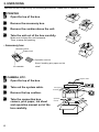
2. UNPACKING
Take the unit out of the box by the following procedures. Make sure to check the contents.
2 PRINTER
1
2
3
4
Open the top of the box.
Remove the accessory box.
Remove the cushion above the unit.
Take the unit out of the box carefully.
Make sure to keep the unit horizontal.
Then, unwrap the packing.
• Accessory box
Remote control
Power cord
Operation manual
Sheet “Installing print paper and ink
Ink cassette
sheet”
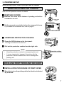
2 CAMERA, ETC.
1
2
3
4
6
System cable
Open the top of the box.
Take out the system cable.
Print paper
Connection box
Ink sheet
Remove the top cushion.
Camera
Take the connection box,
camera, print paper, ink sheet
and operation manual out of the
box carefully.
Operation
manual
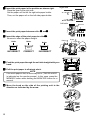
3. PRINTER SETUP
Before printing a photo, install a print paper and ink cassette.
REMOVING SCREW AND CUSHION
See CP710E operation manual for details.
2 REMOVING SCREW
1 Remove the screw at the bottom of printing unit with a
screwdriver or coin.
Transport
screw
2 Set the removed screw to the hole on the rear panel to keep.
If you attach the connection box, refer to page 11.
Stored position
1
2
REMOTE
S-VIDEO
VIDEO
AC LINE
2 REMOVING PROTECTIVE CUSHION
1 Press the OPEN button on the front panel.
Printing unit advances to the front.
2 Pull out the protective cushion from the right side.
NOTE
•
•
Keep the protective cushion for transporting this unit.
It is very important to transport this printer with the
Protective cushion
protective cushion installed so as not to damage the
printing unit.
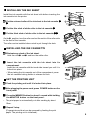
INSTALLING PRINT PAPER AND INK SHEET
INSTALLATION PROCEDURE OF PRINT PAPER
1 Move the knob on the printing unit to the direction indicated
1
by the arrow.
7
2 Insert the print paper in the position as shown right.
Place the gear to the right side.
Set the paper roll first on the right side paper holder.
Then, set the paper roll on the left side paper holder.
Right side
Holder
Print paper
Install
Left side
Holder
3 Insert the print paper between roller 1 and 2.
4 Insert the edge of the print paper to roller 3.
Print paper
Be sure to insert the paper straight.
Roller 3
Roller
Paper
INCORRECT
Roller
Roller
Paper
Paper
CORRECT
Roller 2
Roller 1
INCORRECT
Print paper
5 Feed the print paper through the exit slot straight with your
hand.
6 Pull the print paper to eliminate slack.
NOTE
If too much paper is fed, an error may occur. ("PAPER JAM12"
is indicated on the monitor screen.) In this case, press the
MEMORY button while holding the MONITOR button for a
second.
7 Move the knob on the side of the printing unit to the
direction as indicated by the arrow.
1
8
INSTALLING THE INK SHEET
White roller
Install the ink cassette with the ink sheet rolls before inserting the
ink cassette into the printer.
E
1 Put the coloured roller of the ink sheet to the ink cassette. A
B
B
C
A
2 Put the thin stick of white roller to the ink cassette. C
3 Put the thick stick of white roller to the ink cassette. DE
Coloured roller
E
D
D
On the position, turn the roller and set the notch of the roller side
to the hole of the cassette.
The roller can be installed when notch is put through the hole.
notch
INSTALLING THE INK CASSEETTE
1 Eliminate any slack of the ink sheet.
Hold the roller
2
A
A and B and turn the white roller.
Insert the ink cassette with the ink sheet into its
compartment.
Insert the ink cassette with the knob side toward you until it is
locked into place.
B
• When taking the ink cassette out of the compartment, press
the ink cassette locking holder to release the lock.
SET THE PRINTING UNIT
1 Push the printing unit until it is locked into place.
2 After plugging the power cord, press POWER button on the
front panel.
3 Press the MEMORY button for about 1 second while holding
the MONITOR button on the front panel .
• The print paper is automatically cut after sending by about
10cm.
4 Repeat 3 step.
(Fingerprints and dust can be removed by feeding the print
paper. The printing unit is initialized.)
9
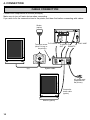
4. CONNECTION
CABLE CONNECTION
Connect the components as follows.(example)
Make sure to turn off each device when connecting.
If you wish to fix the connection box to the printer, set them first before connecting with cables.
Strobe
(option)
1
2
REMOTE
S-VIDEO
Transport screw
(when fixing to
the printer)
(or)
VIDEO
To S-VIDEO IN To VIDEO
OUT
AC LINE
To AC LINE
To
REMOTE
System cable
AC power cord
(supplied with
the printer)
Composite
video cable
(option)
Monitor (option)
10
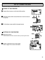
SET UP CONNECTION BOX
There are two ways to set connection box.
FIXING TO THE PRINTER
1
1 Loosen three screws on the back of the printer.
2
REMOTE
S-VIDEO
VIDEO
AC LINE
2 Catch the hooks of the connection box on each screws on
the printer.
Printer
Connection box
Hook
3 Fix the three screws and the transport screw.
Screw
1
2
REMOTE
S-VIDEO
VIDEO
AC LINE
PUTTING ON THE PRINTER
Remove
1 Remove the hook.
Take the hook out of the connection box by removing the screw.
2 Put the connection box on the printer.
1
Refer to page 10 to connect with cables.
2
REMOTE
S-VIDEO
VIDEO
AC LINE
11
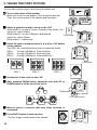
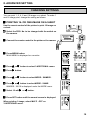
5. TAKING THE FIRST PICTURE
You can take a picture twice, and choose the better one.
1 Turn on the power of this system.
Make sure to turn on the power of the connection box first.
Then, turn on the power of the camera and the printer.
MONITOR
ALARM
SHEET
PAPER
MEMORY
PRINT
S-VIDEO
POWER
OPEN
REMOTE
2 Attach a guide sheet with a circle on the LCD.
Guide sheet A : for use in France, Germany, Italy, Spain, U.K.
(face size : about 23mm)
Guide sheet B : for use in Belgium, Netherlands
Guide sheet
(face size : about 30mm)
Guide sheet C : blank sheet
3 Select the type of mutiple picture (2, 4 or 6) by 1/2/3 button
on the camera.
The PRG. No. is switched every time you press the button.
PRG.1
2-image (45x60mm) (Use solid line.)
PRG.2
4-image (35x45mm) (Use solid line.)
PRG.3
6-image (30x35mm) (Use dotted line.)
1/2/3 button
PRG.1
PRG. 2
PRG. 3
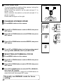
4 Set the face in the circle on the LCD.
5 After pressing ZOOM button, adjust the size with UP or
DOWN button to fit the face in the circle.
SET
DOWN
UP
ZOOM button
UP, DOWN button
6 Wait for about 3 seconds until auto focus function is
completed.
7 Press SHOT button to take a picture.
The first image is memorized in the camera.
12
1st image
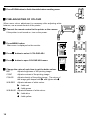
8 Press MEM button to transfer the image to the printer.
The image is memorized in the printer.
9 Press SHOT button to display the source image.
A Press SHOT button again.
The second image is memorized in the camera.
2nd image
B Select the image to be printed.
Press C/P button to switch between the two images.
“C”(image in the camera) or “P”(image in the printer) is shown
on the LCD.
C/P
C Print the image.
When printing the first image (with “P” mark, an image
memorized in the printer), press PRINT button.
PRINT
Printed
image
When printing the second image (with “C” mark, an image
memorized in the camera), press MEM button first, then, press
PRINT button.
MEM
7
When printing only one image (not multiple picture), skip the step
.
PRINT
Printed
image
Refer to page 14 to get maximum quality of your pictures.
13
6. PICTURE QUALITY ADJUSTMENT
ADJUSTING PICTURE QUALITY
To adjust the image source first is the key to get maximum
picture quality.
2 CAMERA ADJUSTMENT
Always adjust the camera setting first. Only after you are sure
that the camera is providing the best picture quality and colour
balance, adjust the printer setting.
Make sure to adjust the camera setting in the same condition
which you actually take a picture.
For Iris setting, see the table shown right.
2 ADJUSTING THE BRIGHTNESS OF IMAGE (IRIS)
Relation Distance for taking picture, Guide No., F number
Distance (m)
1
1.5
2.5
2
F IRIS
F IRIS
F IRIS
F IRIS
12
8 -17
14
5.6 13
16 16 -24
11 -20
8 -17
18
20
8 -17
11 -20
22 22 -28
16 -24
24
26
11 -20
Guide 28
30
No.
32 32 -30 22 -28 16 -24
34
36
38
40
16 -24
42
44
22 -28
46
48
32 -30
50
52
54
22 -28
56
1 Press SHOT button to take a picture.
SHOT
MANUAL
2 Press IRIS button.
IRIS adjustment mode is selected.
0
3 Press UP or DOWN button to select MANUAL.
Good
Too light
5 Press SET button.
6 Press ZOOM button to finish the iris setting menu.
14
-20
Too dark
MANUAL
The set value is flashing. Change the set value with UP or DOWN
button.
If the image is too dark, set the larger value.
If the image is too light, set the smaller value.
IRIS
4 Press SET button.
7 Press SHOT button to take a picture.
Check the brightness of image.
If the brightness is not improved, repeat the steps
get the best setting.
2 to 6 to
2 ADJUSTING THE COLOUR OF IMAGE (WHITE BALANCE)
Default setting is flash light W.B. If you are not satisfied with this
setting, please proceed as follows.
1 Place a piece of white paper in front of the camera and
display it to cover the LCD.
Place white paper at the actual position where the subject would
normally sit.
NOTE
Do not display the picture with non-white objects when adjusting
white balance.
Adjust white balance under sufficient light.
a piece of
white paper
camera
actual distance of a person
who is taking a picture
2 Press SHOT button with flashing a strobe light to take a
picture.
White balance adjustment mode is selected.
PRG.1
WB
PRESET
3 Press WB button.
(UP)
(DOWN)
WB
4 Press UP or DOWN button to select LOCK.
LOCK
WB
5 Press SET button for about 5 seconds until white balance
is locked.
LOCK
5 sec.
15
6 Press ZOOM button to finish the white balance setting menu.
2 FINE-ADJUSTING OF COLOUR
When more colour adjustment is necessary after adjusting white
balance, use a remote control of the printer.
1 Connect the remote control to the printer or the camera.
MONITOR
ALARM
SHEET
PAPER
MEMORY
PRINT
S-VIDEO
or
POWER
OPEN
REMOTE
If the printer is not turned on, turn on the power.
DISPLAY
COLOR
ADJUST
PROG.
DISPLAY
FIELD
/FRAME
COLOR
ADJUST
PROG.
FIELD
/FRAME
+
+
-
-
PRINT
Q' ty
MENU
PRINT
Q' ty
SET
CLEAR
MENU
STOP
MEMORY
SET
CLEAR
MEMORY
PAGE
MONITOR
STOP
MEMORY
PAGE
MONITOR
PRINT
MEMORY
PRINT
2 Press MENU button.
PRINT
Q' ty
Main menu is displayed on the monitor.
MENU
SET
CLEAR
STOP
3 Press } button to select 1.COLOUR ADJ.
PRINT
Q' ty
MENU
SET
CLEAR
STOP
]
1. COLOR ADJ
PRINT MODE : COLOR/MONO
: 0
BRT
: 0
CONT
: 0
COLOR
: 0
TINT
W.B-RED : 0
W.B-BLUE : 0
FINE ADJ : PUSH [ ]
CHANGE: OK/CANCEL
4 Press ] button to open COLOUR ADJ menu.
+
-
5 Change the value of each item to get the better colour.
Adjusts brightness of the printing image.
CONT
Adjusts contrast of the printing image.
COLOR
Adjusts density of the priting image. The colour of
the image gets deeper with
and lighter with .
W.B-RED
Adjusts redness of white colour.
] : Adds red
[ : Adds green
W.B-BLUE Adjusts blueness of white colour.
] : Adds blue
[ : Adds yellow
16
PRINT
Q' ty
MENU
BRT
]
+
-
[
SET
7. FEATURES AND FUNCTIONS
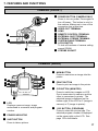
CAMERA (FRONT)
8
9
3
21
54
6
7
SHOT
B/W
MEM
IRIS
WB
MENU
PRINT
ZOOM
C/P
1/2/3
23
4
6 75
SET
DOWN
1 LCD
UP
8
Displays a source image, image
memorized in a camera, and program
number.
2 POWER INDICATOR
3 SHOT BUTTON
2
3
4
5
6
7
8
9
Press to turn on power. Press again to
turn off power. This button is only for
the camera. Make sure to turn on the
connection box at this time.
VIDEO-OUT TERMINAL
LENS
REMOTE CONTROL TERMINAL
EXTERNAL SHOT TERMINAL
EXTERNAL STROBE TERMINAL
SYSTEM CABLE TERMINAL
LOCK SWITCH
To lock all functions of camera setting
except ZOOM.
STROBE SOCKET
CAMERA (REAR)
1
DC
B
9A
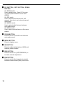
1 POWER BUTTON (CAMERA ONLY)
4 MEM BUTTON
Press to memorize an image into the
printer.
5 PRINT BUTTON
Press to print an image in the printer.
6 C/P BUTTON (MONITOR)
Press to switch two images on LCD.
One is memorized in camera, and the
other is memorized in printer. The
selected image is displayed on the
bottom-right of the LCD as C (image in
camera) or P (image in printer).
7 1/2/3 BUTTON (PROGRAM)
Press to select the picture type. The
selected program number is displayed
on the upper-right on the LCD. See
page 12 for the details.
Press to take a picture.
17
8 UP BUTTON, SET BUTTON, DOWN
BUTTON
On ZOOM mode:
Use to adjust zoom. Press UP to zoom
up (TELE) and DOWN to zoom back
(WIDE).
On IRIS mode:
Use to switch iris between auto and
manual. Use also to set value at manual
adjustment.
On WB/PR mode:
Use to switch white balance between
auto and manual.
On MENU mode:
Use to select and set items on the menu
screen.
9 ZOOM BUTTON
Press to zoom or switch focus between
auto and manual.
A MENU BUTTON
Press to display menu.
B WB BUTTON
Press to adjust white balance (W/B) and
select a preset number.
C IRIS BUTTON
Press to switch iris (AUTO/MANUAL) or
to make manual adjustment.
D B/W BUTTON
Press to switch the image to be printed
between monochrome (B/W) and colour.
18
8. ADVANCED SETTING
CHANGING SETTINGS
You can print 1, 2, 4, 6 and 16-image on a sheet. To make 1
and 16-image print, change the setting as follows.
2 PRINTING 16- OR ONE-IMAGE ON A SHEET
Use the remote control of the printer to print 16-image on
a sheet.
1 Select the PRG. No. to be changed with the switch on
the camera.
MONITOR
ALARM
2 Connect the remote control to the printer or the camera.
SHEET
PAPER
MEMORY
PRINT
S-VIDEO
or
POWER
OPEN
REMOTE
DISPLAY
DISPLAY
COLOR
ADJUST
PROG.
FIELD
/FRAME
COLOR
ADJUST
PROG.
FIELD
/FRAME
+
+
-
PRINT
Q' ty
PRINT
Q' ty
MENU
SET
MENU
CLEAR
MEMORY
3 Press MENU button.
SET
CLEAR
STOP
MEMORY
PAGE
MONITOR
STOP
MEMORY
PAGE
MONITOR
MEMORY
PRINT
PRINT
PRINT
Q' ty
MENU
MAIN MENU is displayed on a monitor.
SET
CLEAR
STOP
+
4 Press { or } button to select 3.ADDITIONAL menu.
5 Press ] button.
PRINT
Q' ty
MENU
SET
CLEAR
STOP
6 Press { or } button to select MODE : SAME/ID.
7 Press ] or [ button to select MODE : SAME.
IMAGES : 2/4/16 is displayed under the MODE menu.
8 Select 16 with ] or [ button.
9 Press SET button until the normal screen is displayed.
When printing 1-image, select MULTI : OFF on
3.ADDITIONAL menu.
19
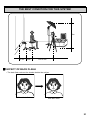
"L" is indicated
on red.
U
2 CHANGING ZOOMING SPEED
LENS
SET button.
ZOOM
FOCUS
RETURN
3 Press UP or DOWN button to select ZOOM, then press
LENS
BRIGHT
STROBE
------DETAIL
COLOR
SUB-MENU
PRESET-WRITE
END
SET button.
MENU
1 Press MENU button on the camera.
2 Press UP or DOWN button to select LENS, then press
4 Press UP or DOWN button to select SPEED, then press
2 SELECTING AUTO/MANUAL FOCUS
1 Press MENU button on the camera.
2 Press UP or DOWN button to select LENS, then press
SET button.
3 Press UP or DOWN button to select FOCUS, then press
SET button.
4 Press UP or DOWN button to select AUTO or MANUAL,
then press SET button.
When selecting MANUAL, press UP or DOWN button to
select the focus, then press SET button.
Normally, use MANUAL mode for focus
setting.
20
ZOOM
SPEED
RETURN
among SLOW, MEDIUM, FAST and VERY FAST.
ZOOM
SET button.
5 Press UP or DOWN button to select zooming speed
"U" is indicated
on green.
L
To avoid changing the setting of the camera, locking the
camera setting is recommended.
When locked, the switch is on the right side and “L” is
shown on red.
When unlocked, the switch is on the left side and “U” is
shown on green.
Please see the figure on the right.
U
2 LOCK FUNCTION
THE BEST CONDITION FOR THIS SYSTEM
2m
MONITOR
ALARM
SHEET
PAPER
MEMORY
PRINT
S-VIDEO
POWER
OPEN
REMOTE
0.3m
0.3m
1.5m to 2m
2 EFFECT OF BACK FLASH
• The back flash reduces the shadow behind the subject.
Without back flash
With back flash
21
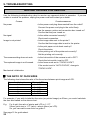
9. TROUBLESHOOTING
BEFORE CALLING FOR SERVICE
Use the following troubleshooting chart to resolve any apparent defect in operation. If you are
unable to resolve the problem, unplug the power cord and contact your dealer.
Causes
Countermeasures
No power
• Is the power cord plug disconnected from the outlet?
Connect the power cord plug to the outlet firmly.
• Are the camera, printer and connection box turned on?
Confirm that they are turned on.
No signal
• Is the cable connected correctly?
Check each connection.
Image is not printed.
• Is the image data sent to the printer?
Confirm that the image data is sent to the printer.
• Is the print paper or ink sheet used up?
Check the status.
• Is the printing unit of the printer set correctly?
Set the printing unit correctly.
The camera setting does not work.
• Is the lock switch of the camera is set to OFF?
Check the lock switch is set to OFF.
The captured image is not focused.
• Is the focus mode set to “FOCUS LOCK”?
If the mode is set to “AUTO FOCUS”, change to
“FOCUS LOCK”.
Mechanical initialization
2 THE RATIO OF FACE SIZES
The following chart shows the ratio of the face sizes between print image and LCD.
Type of multiple picture
1
2
4
6
16
Printer / LCD
1 : 0.87
1 : 1.33
1 : 1.77
1 : 1.35
1 : 3.50
For example, if you wish to take the face size (on printed image) as 25mm, you would calculate
the face size based on the above chart.
E.g.
For 4-split, the ratio of printer and LCD is 1:1.77.
25mm (print size) x 1.77 (ratio) = about 44mm (on LCD)
So, you can mark a new circle on guide C.
See page 12 for guide sheet.
22
10. SPECIFICATIONS
Printer
Camera
Printing method
Sublimation Dye thermal
Image pickup device
1/4" CCD (total 470,000 pixels)
No. of effective pixels
752H x 582V (440,000 pixels)
Signal system
PAL colour system
Scanning system
625 lines; 2:1 interlace
Scanning frequency
15.625 kHz (H), 50 Hz (V)
Sync. system
Internal
Printng time
Video output
PAL composite
Ink sheet
Special cartridge method
Horizontal resolution
430 TV lines (S-video output)
Print paper
Special roll paper L size 162x110mm
S/N ratio
More than 46dB
Gain control
AUTO / MANUAL
White balance
AUTO / INDOOR/ FL LIGHT /
OUTDOOR / LOCK / MANUAL
Special roll paper S size 110x107mm
Color adjustment
R-GAIN / B-GAIN / R-HUE / B-HUE
Printing area
Electronic SHOT
1/50
Closest distance
1cm (widest angle) 1m (telephoto
end)
Lens
(yellow, magenta and cyan)
Print quality
Dot resolution max.1200x600 dots
Number of grades 256 for each color
Approx. 40sec./sheet (S size one image print)
Printing area
Wide mode
130x96mm
Middle mode 122x93mm
Narrow mode 118x89mm
Wide mode
100x73mm
Middle mode 94x71mm
Electrically powered 14-power
zoom lensF1.4, f = 3.9 - 54.6mm
Zoom speed 2 / 3 / 6 / 10 sec.
Focus
AUTO / LOCK / MANUAL
Iris
AUTO/MANUAL
Temperature
Operating
0°C to 40°C
Safekeeping -20°C to +60°C
Current consumption
DC12V 900mA
Narrow mode 91x68mm
Supply method
Automatic
Input terminal
Composite video (1 BNC type connector)
S-VIDEO (1 S-VIDEO terminal)
Output terminal
Composite video (1 BNC type connector)
S-VIDEO (1 S-VIDEO terminal)
Input/Output terminal
Remote terminal 1 (stereo mini jack)
Remote terminal 2 (Mini DIN 8 pin)
(camera+LCD+video amp+PCB’s)
External dimensions
3 colour faces progressive printing
Input frequency
H frequency 15.625kHz
V frequency 50Hz
165mm(W) x 147mm(H) x 205mm(D)
(excluding external connectors)
Power supply
AC 220-240V, 50Hz
Weight
Approx. 1kg
Power consumption
1.0A during printing
LCD
4 inch
Installation conditions
Accesories
Operation Manual
Temperature 5°C to 40°C
Humidity 20 to 80% (no dewing)
Operation altitude
Horizontal ± 5°
Guide sheet (3)
Print paper
Ink sheet
Connection box
Output terminal
Composite video PAL
RS-232C
Mini DIN (camera control)
Power supply
AC 220-240V, 50Hz
Power consumption
0.6A (Inrush current 1.2A)
Installation conditions
Temperature
External dimensions
214mm(W) x 85mm(H) x 110mm(D)
External dimensions
280mm(W)x150mm(H)x398mm(D)
Weight
14.5kg
Accesories
Operation Manual
Remote control
Ink-cassette
Power cord
Spacer (4)
Additional sheet
“Installing print paper and ink sheet”
5°C to 40°C
(excluding external connectors)
Weight
Approx. 1.5kg
Accesories
System cable
• Specifications are subject to change without notice.
23
Name of Importers
Mitsubishi Electric Europe B.V.
Benelux Branch
Nijverheidsweg 23 A, 3641 RP. Postbus 222, 3640 AE Mijdrecht
Phone 02972-82461
FAX 02972-83936
French Branch
25, Boulevard des Bouvets - 92741 NANTERRE cedex
Phone (01) 55.68.55.00
FAX (01) 55.68.57.31
German Branch
Gothaer Strasse 8, Postfach 1548, 40880 Ratingen 1, Germany
Phone (02102) 4860
FAX (02102) 486-732
Irish Branch
Westgate Business Park, Ballymount, Dublin 22, Ireland
Phone (1) 4505007
FAX (1) 4561337
Italian Branch
Centro Direzionale Colleoni, Palazzo Perseo-Ingresso 2,
Via Paracelso 12, 20041 Agrate Brianza, (Milano) Italy
Phone (039) 60531
FAX (039) 6057694
Scandinavian Branch
Hammarbacken 14, Box 750 S-19127, Sollentuna, Sweden
Phone (8) 625-1000
FAX (8) 966877
Spanish Branch (Barcelona)
Sucursal en España
Polígono Industrial "Can Magí", Calle Joan Bucallà 2-4,
Apartado de Correos 420, 08190 Sant Cugat del Vallés,
Barcelona, Spain
Phone 93.5653154
FAX 93.5894388
UK Branch
Travellers Lane, Hatfield, Herts. AL10 8XB, England, U.K.
Phone (1) 707 276100
FAX (1) 707 278755
MITSUBISHI ELECTRIC CORPORATION
IDSYS-F1
Made from recycled paper
PRINTED IN JAPAN