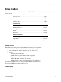
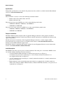
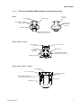
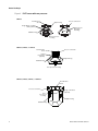
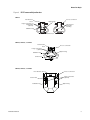
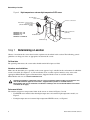
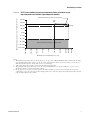
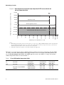
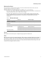
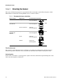
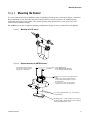
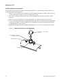
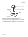
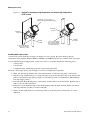
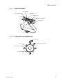
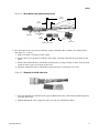
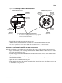
1
Installation Manual
P/N 20002158, Rev. C
September 2007
Micro Motion®
ELITE® Sensors
Installation Manual
©2007, Micro Motion, Inc. All rights reserved. ELITE and ProLink are registered trademarks, and MVD and MVD Direct Connect
are trademarks of Micro Motion, Inc., Boulder, Colorado. Micro Motion is a registered trade name of Micro Motion, Inc., Boulder,
Colorado. The Micro Motion and Emerson logos are trademarks and service marks of Emerson Electric Co. All other trademarks
are property of their respective owners.
Before You Begin
Before You Begin
This manual describes how to install a Micro Motion® ELITE® sensor. The following information is provided
in this manual:
Customer service . . . . . . . . . . . . . . . . . . . . . . . . . . . . . . . . . . . . . . . . . . . . . . . page 1
Definitions . . . . . . . . . . . . . . . . . . . . . . . . . . . . . . . . . . . . . . . . . . . . . . . . . . . . . page 2
European installations . . . . . . . . . . . . . . . . . . . . . . . . . . . . . . . . . . . . . . . . . . . page 2
Installation options . . . . . . . . . . . . . . . . . . . . . . . . . . . . . . . . . . . . . . . . . . . . . . page 2
Installation steps
Determining a Location. . . . . . . . . . . . . . . . . . . . . . . . . . . . . . . . . . . . . . . . . . . page 6
Orienting the Sensor. . . . . . . . . . . . . . . . . . . . . . . . . . . . . . . . . . . . . . . . . . . . page 10
Mounting the Sensor . . . . . . . . . . . . . . . . . . . . . . . . . . . . . . . . . . . . . . . . . . . page 11
Wiring . . . . . . . . . . . . . . . . . . . . . . . . . . . . . . . . . . . . . . . . . . . . . . . . . . . . . . . page 16
Grounding . . . . . . . . . . . . . . . . . . . . . . . . . . . . . . . . . . . . . . . . . . . . . . . . . . . . page 20
Additional information
Pressure Ratings . . . . . . . . . . . . . . . . . . . . . . . . . . . . . . . . . . . . . . . . . . . . . . page 20
Purge Fittings . . . . . . . . . . . . . . . . . . . . . . . . . . . . . . . . . . . . . . . . . . . . . . . . . page 21
Rupture Disks . . . . . . . . . . . . . . . . . . . . . . . . . . . . . . . . . . . . . . . . . . . . . . . . . page 22
Return Policy . . . . . . . . . . . . . . . . . . . . . . . . . . . . . . . . . . . . . . . . . . . . . . . . . page 23
Customer service
For technical assistance, phone the Micro Motion Customer Service department:
• In the U.S.A., phone 800-522-MASS (800-522-6277) (toll free)
• In Canada and Latin America, phone +1 303-527-5200 (U.S.A.)
• In Asia:
-
In Japan, phone 3 5769-6803
-
In other locations, phone +65 6777-8211 (Singapore)
• In Europe:
-
In the U.K., phone 0870 240 1978 (toll-free)
-
In other locations, phone +31 (0) 318 495 555 (The Netherlands)
Customers outside the U.S.A. can also email Micro Motion customer service at
[email protected].
Troubleshooting
Refer to the transmitter manual for troubleshooting help.
Installation Manual
1
Before You Begin
Specifications
Full product specifications can be found in the product data sheet, which is available from the Micro Motion
web site at www.micromotion.com.
Definitions
The term MVD™ transmitter refers to the following transmitter models:
• Models 1500, 1700, 2400S, 2500, and 2700
• Models 3500 and 3700
The term high-temperature ELITE sensor refers to the following model codes:
• CMF200A, CMF300A, CMF400A, and CMFHC3A
• CMF200B and CMF300B
The term extreme high-temperature ELITE sensor refers to the following model codes:
• CMF200C, CMF300C, CMF400C, and CMFHC3C
• CMF200E and CMF300E
European installations
This Micro Motion product complies with all applicable European directives when properly installed in
accordance with the instructions in this manual. Refer to the EC declaration of conformity for directives that
apply to this product.
The EC declaration of conformity, with all applicable European directives, and the complete ATEX
Installation Drawings and Instructions are available on the internet at www.micromotion.com/atex or
through your local Micro Motion support center.
Information affixed to equipment that complies with the Pressure Equipment Directive can be found on the
internet at www.micromotion.com/documentation.
Installation options
The ELITE sensor makes up one part of a Coriolis flowmeter. The other part is a transmitter. ELITE sensors
are available with the following electronics interfaces:
• An integral Model 2400S transmitter or enhanced core processor (see Figure 1).
• An integral core processor for connecting to a 4-wire remotely mounted transmitter or to a
user-supplied remote host (see Figure 2).
• A 9-wire junction box for connecting to a remotely mounted transmitter or a remotely mounted core
processor (see Figure 3).
• High-temperature and extreme high-temperature models are equipped with a flexible conduit, on
which can be mounted a Model 2400S transmitter, a Model 1700/2700 transmitter, a core processor, or
a junction box (see Figure 4).
2
Micro Motion® ELITE® Sensors
Before You Begin
Figure 1
ELITE sensor with Model 2400S transmitter or enhanced core processor
CMF010
Process
connection
Flow direction
arrow
Approval tag
Purge fittings or rupture
disks (optional)
Thru holes for
alternative
mounting
Calibration tag
Model 2400S transmitter or
enhanced core processor
CMF025, CMF050, or CMF100
Flow direction
arrow
Purge
connections
(optional)
Process connection
Approval tag
Model 2400S transmitter or
enhanced core processor
Calibration tag
CMF200, CMF300, CMF400, or CMFHC3
Flow direction
arrow
Process connection
Purge connections
(optional)
Model 2400S transmitter or
enhanced core processor
Approval tag
Calibration tag
Installation Manual
3
Before You Begin
Figure 2
ELITE sensor with core processor
CMF010
Flow direction
arrow
Process connection
Approval tag
Purge fittings or rupture
disks (optional)
Thru holes for
alternative
mounting
Calibration tag
Core processor
housing
CMF025, CMF050, or CMF100
Flow direction
arrow
Process connection
Purge
connections
(optional)
Approval tag
Calibration tag
Core processor housing
CMF200, CMF300, CMF400, or CMFHC3
Flow direction
arrow
Process connection
Purge connections
(optional)
Core
processor
housing
Approval tag
Calibration tag
4
Micro Motion® ELITE® Sensors
Before You Begin
Figure 3
ELITE sensor with junction box
CMF010
Process connection
Flow direction
arrow
Approval tag
Purge connections or
rupture disks
(optional)
Thru holes for
alternative
mounting
Calibration tag
Junction box
CMF025, CMF050, or CMF100
Flow direction
arrow
Process connection
Purge connections
(optional)
Approval tag
Calibration tag
Junction box
CMF200, CMF300, or CMF400
Flow direction arrow
Junction box
Calibration tag
Installation Manual
Process connection
Purge connections
(optional)
Approval tag
5
Determining a Location
Figure 4
High-temperature or extreme high-temperature ELITE sensor
Flow direction
arrow
Process connection
Transmitter, core processor,
or junction box
(Model 2400S transmitter
shown)
CMF200A, B, C, or E
CMF300A, B, C, or E
CMF400A or C
CMFHC3A or CMFHC3C
Purge connections
(optional)
Flexible conduit
Approval tag
Calibration tag
Step 1 Determining a Location
Choose a location for the sensor based on the requirements described in this section. The following general
guidelines can help you select an appropriate location for the sensor.
Full flow tubes
For optimal performance, the sensor tubes should remain full of process fluid.
Hazardous area installations
Make sure the hazardous area specified on the sensor approval tag is suitable for the environment in which the
sensor is installed. (See Figures 1–4.) For installation in an area that requires intrinsic safety, refer to the
appropriate Micro Motion approval documentation, shipped with the sensor or available from the
Micro Motion web site at www.micromotion.com.
Improper installation in a hazardous area can cause an explosion. When installing in a hazardous area,
refer to Micro Motion approvals instructions, shipped with the product or available from the
Micro Motion web site. For hazardous installations in Europe, refer to standard EN 60079-14 if national
standards do not apply.
Environmental limits
The ambient and process temperature limits of the sensor are shown in Figures 5 and 6:
• For ELITE sensor models other than high-temperature and extreme-high temperature models, see
Figure 5.
• For high-temperature and extreme high-temperature ELITE sensors, see Figure 6.
6
Micro Motion® ELITE® Sensors
Determining a Location
Figure 5
ELITE sensor ambient and process temperature limits (all models except
high-temperature and extreme high-temperature models)
176 (80)
140
(60)
140 (60)
113 (45)
104 (40)
68 (20)
32 (0)
–4 (–20)
–40 (–40)
–76 (–60)
Mount transmitter remotely; use junction box
–112 (–80)
464 (240)
400 (204)
356 (180)
248 (120)
140 (60)
32 (0)
–76 (–60)
–184 (–120)
–292 (–180)
–148 (–100)
–400 (–240)
Ambient temperature of core processor or transmitter in °F (°C)
Mount transmitter remotely; use junction box
Maximum process temperature in °F (°C)
Notes:
1. When ambient temperature is below –40 °F (–40 °C), a core processor or Model 2400S transmitter must be heated to bring
its local ambient temperature to between –40 °F (–40 °C) and +140 °F (+60 °C). Long-term storage of electronics at
ambient temperatures below –40 °F (–40 °C) is not recommended.
2. Temperature limits may be further restricted by hazardous area approvals.
3. The extended mount option allows the sensor case to be insulated without covering the transmitter, core processor, or
junction box, but does not affect temperature ratings.
4. For the purposes of selecting electronics options, this graph should be used only as a general guide. If your process
conditions are close to the gray areas, it may be inappropriate to use electronics options other than a junction box. Consult
with your Micro Motion representative.
Installation Manual
7
Determining a Location
High-temperature and extreme high-temperature ELITE sensor ambient and
process temperature limits
176 (80)
662
(350)
140 (60)
104 (40)
High-temp. models
68 (20)
32 (0)
Extreme high-temp. models
–4 (–20)
–40 (–40)
–76 (–60)
Mount transmitter remotely; use junction box
–112 (–80)
842 (450)
800 (427)
752 (400)
662 (350)
572 (300)
482 (250)
392 (200)
302 (150)
212 (100)
122 (50)
32 (0)
–148 (–100)
–58 (–50)
Ambient temperature of core processor or transmitter in °F (°C)
Figure 6
Maximum process temperature in °F (°C)
Notes:
1. When ambient temperature is below –40 °F (–40 °C), a core processor or Model 2400S transmitter must be heated to bring
its local ambient temperature to between –40 °F (–40 °C) and +140 °F (+60 °C). Long-term storage of electronics at
ambient temperatures below –40 °F (–40 °C) is not recommended.
2. Temperature limits may be further restricted by hazardous area approvals.
Hazardous area approvals may impose additional limits on ambient and process temperature. For the ATEX
“T” rating, refer to the ATEX documentation shipped with the sensor or available on the Micro Motion web
site at www.micromotion.com. IECEx and NEPSI approvals also use the ATEX “T” rating. UL and CSA
ambient temperature limits are listed in Table 1.
Table 1
UL and CSA ambient temperature limits
UL
Sensor models
All models
CSA
All models
All models except CMF400
CMF400
8
Electronics
Junction box
Core processor
Junction box
Core processor
2400S transmitter
2400S transmitter
°F
+104 maximum
–40 to +104
+140 maximum
–40 to +140
–40 to +140
–58 to +140
°C
+40 maximum
–40 to +40
+60 maximum
–40 to +60
–40 to +60
–50 to +60
Micro Motion® ELITE® Sensors
Determining a Location
Maximum wiring distances
If the transmitter is mounted remotely from the sensor, the maximum distance between the sensor and
transmitter depends on cable type. See Table 2.
For high-temperature and extreme high-temperature ELITE sensors, note the following:
• For sensors with a Model 1700/2700 or a Model 2400S transmitter, the transmitter is considered to be
integrally mounted on the sensor, so Table 2 does not apply.
• For sensors with a junction box or core processor, the limits in Table 2 apply only to the wiring
between the junction box or core processor and a remotely-mounted transmitter. The length of the
flexible conduit on which the junction box or core processor is mounted does not need to be
considered.
Table 2
Maximum cable lengths
Cable type
Wire size
Maximum length
Micro Motion 9-wire to an MVD
transmitter or core processor
Not applicable
60 feet (20 meters)
Micro Motion 9-wire to all other
transmitters
Not applicable
1000 feet (300 meters)
Micro Motion 4-wire
Not applicable
1000 feet (300 meters)
User-supplied 4-wire
Power wires (VDC)
22 AWG (0,35 mm2)
2
20 AWG (0,5 mm )
2
18 AWG (0,8 mm )
Signal wires (RS-485)
2
22 AWG (0,35 mm ) or larger
300 feet (90 meters)
500 feet (150 meters)
1000 feet (300 meters)
1000 feet (300 meters)
Pipe run
Micro Motion sensors do not require a straight run of pipe upstream or downstream.
Valves
Meter zero can be adjusted for special circumstances. When zeroing is performed with the auto-zero feature of
the transmitter, it is necessary to halt flow through the sensor, with the sensor tubes full of process fluid at
typical process conditions. The valve used to halt flow in this situation should be downstream from the sensor.
It is also possible to restore the meter’s factory zero setting. For more information about zeroing, refer to the
instruction manual shipped with the transmitter.
Installation Manual
9
Orienting the Sensor
Step 2 Orienting the Sensor
The sensor will function properly in any orientation if the sensor tubes remain filled with process fluid.
Micro Motion recommends orienting ELITE sensors as shown in Table 3.
Table 3
Recommended sensor orientations
Sensor model
Application
Recommended orientation
CMF010
All applications
Tubes flat
Horizontal pipeline
CMF025, CMF050,
and CMF100
Liquids
Tubes down
Horizontal pipeline
Gases and slurries
Tubes up
Horizontal pipeline
Liquids
Tubes down
Horizontal pipeline
Gases
Tubes up
Horizontal pipeline
Slurries
Flag mount
Vertical pipeline
CMF200, CMF300,
CMF400, and
CMFHC3
Flow direction arrow
The sensor has a flow direction arrow (see Figures 1–4) to help you configure the transmitter for flow
direction. If possible, install the sensor so that the flow direction arrow matches actual process flow.
Vertical pipeline
If the sensor is installed in a vertical pipeline, liquids and slurries should flow upward through the sensor.
Gases may flow upward or downward.
10
Micro Motion® ELITE® Sensors
Mounting the Sensor
Step 3 Mounting the Sensor
Use your common practices to minimize torque and bending load on process connections. Figure 7 illustrates
how to mount the sensor. To reduce the risk of condensation or excessive moisture, the conduit opening
should not point upward (if possible). The conduit opening of the junction box or core processor can be
rotated freely to facilitate wiring.
The CMF010 sensor has an optional mounting configuration (Figure 8) for use with small or soft pipeline.
Figure 7
Mounting an ELITE sensor
Figure 8
Optional mounting for CMF010 sensors
If the pipeline will not support
the sensor, mount the sensor
using bolts as illustrated.
2 × user supplied bolts
• 5/16″ (M8) maximum diameter
• 2 1/4″ (58 mm) minimum length
Junction box or core processor (junction box
shown)
• Junction box can be rotated by hand
(before wiring is attached) for access to
mounting holes
• Core processor does not need to be
rotated for access to mounting holes
If necessary, rigid standoffs (e.g., steel washers)
can be installed
Mounting surface — if pipe supports are used, they
should be rigidly supported by the same mounting
surface that supports the sensor
Installation Manual
11
Mounting the Sensor
Installing extended mount electronics
If you ordered a sensor with an extended mount for the electronics, you will need to install the extender. To
install the extended mount electronics:
1. There is a metal clamping ring around the base of the feedthrough (Figure 9). Remove this ring and set
it aside. You will use it later to secure the extender to the sensor.
2. The sensor was shipped with a plastic cap over the feedthrough pins. Remove the plastic cap and
discard it.
3. There is a plastic plug inside the extended mount (Figure 10). Remove the plug and discard it.
4. Place the extended mount onto the feedthrough and carefully rotate the extender until the feedthrough
notches line up. Being careful not to damage the feedthrough pins, push the extender down onto the
feedthrough until it is fully engaged.
5. Replace the clamping ring on the feedthrough. Tighten the ring’s screw to 13–18 in-lbs (1.5–2 N-m).
Figure 9
Feedthrough, plastic cap, and clamping ring
Plastic cap — remove and
discard
Clamping ring — remove
but do not discard
Clamping ring screw
Feedthrough
12
Micro Motion® ELITE® Sensors
Mounting the Sensor
Figure 10
Mounting the temperature extender onto the sensor
Model 2400S transmitter or enhanced core
processor — preinstalled on the extended
mount
Clamping ring screw —
when extender is engaged,
tighten this to 13–18 in-lbs
(1.5–2 N-m)
Extended mount — carefully align the notches at
the bottom of the extended mount with the
notches on the feedthrough to engage properly
Plastic plug — remove and
discard
Feedthrough — note the
notches for correct
engagement of the extender
Mounting the electronics of high-temperature and extreme high-temperature sensors
High-temperature and extreme high-temperature ELITE sensors come with a 32″ (812 mm) pre-installed
flexible conduit. This conduit is required for agency approval.
A factory-supplied Model 2400S transmitter, Model 1700/2700 transmitter, core processor, or junction box is
connected to the end of the flexible conduit. Mount the electronics to a wall or instrument pole using the
supplied bracket (Figure 11).
Installation Manual
13
Mounting the Sensor
Figure 11
Electronics mounting for high-temperature and extreme high-temperature
ELITE sensors
Transmitter, core processor, or
junction box (Model 2400S shown)
Mounting
bracket
Mounting
bracket
Flexible
conduit
Use 4 × 5/16″ (8 mm)
bolts to secure the
bracket to a wall
Flexible
conduit
Use 2 user-supplied
5/16″ (8 mm) U-bolts
to secure the bracket
to an instrument pole
Installing wafer-style sensors
A wafer-style sensor, which has no flanges or fittings, lets you “clamp” the sensor between process
connections in the pipeline. Model CMF025, CMF050, and CMF100 sensors are available in the wafer style.
A wafer installation kit is shipped with a wafer-style sensor. A wafer kit contains the following pieces:
• 4 flange bolts
• 8 flange nuts
• 2 alignment rings, which help center the sensor between the bolts
To install a wafer-type sensor, refer to Figures 12 and 13 and follow the steps below:
1. Make sure the bolts provided in the wafer installation kit are rated for your process connection.
2. Slip the sensor alignment rings over each end of the sensor wafer, then insert the sensor between the
process connections in the pipeline (Figure 12). Installing gaskets is recommended. (Micro Motion
does not supply gaskets.)
3. Insert the bolts through both process connections, and thread the nuts onto the bolts. Tighten nuts as
tight as you can with your fingers.
4. Rotate the sensor alignment rings in the direction that pushes the bolts outward (Figure 13). Rotate
both rings until the assembly is centered and tight.
5. With a wrench, tighten nuts in an alternating order, to ensure the process connections are evenly
tightened.
14
Micro Motion® ELITE® Sensors
Mounting the Sensor
Figure 12
Wafer-style assembly
Sensor wafer
Process connection
Flange bolt
Alignment ring
Gasket (user-supplied)
Flange nut
Figure 13
Tightening the sensor alignment rings
Rotate the ring...
Sensor wafer
...to push the bolts outward
Sensor alignment ring
Flange bolt
Installation Manual
15
Wiring
Step 4 Wiring
Hazardous area installations
If you are installing the sensor in a hazardous location, verify that the hazardous classification information
printed on the sensor tag matches the environment in which the sensor will be installed.
Improperly sealed housings can expose electronics to moisture, which can cause measurement error
or flowmeter failure. Inspect and grease all gaskets and O-rings. Fully close and tighten all housing
covers and conduit openings.
Installation options
The sensor has one of the following configurations:
• An integral Model 2400S (all models) or Model 1700/2700 transmitter (high-temperature and extreme
high-temperature models only). No wiring is required between the sensor and the transmitter. Skip to
Grounding on page 20.
• A core processor to a 4-wire remote transmitter (requires 4-wire cable); see Core processor to a 4-wire
remote transmitter on page 16.
• A core processor to a remote host (requires 4-wire cable); refer to the Micro Motion MVD™ Direct
Connect™ Meters Installation Manual.
• A junction box to a 9-wire remote transmitter or remote core processor (requires 9-wire cable); see
Junction box to a 9-wire remote transmitter or remote core processor on page 19.
Core processor to a 4-wire remote transmitter
Follow the steps below to connect the 4-wire cable between the core processor and the transmitter.
1. Use one of the following methods to shield the wiring from the core processor to the transmitter:
• If you are installing unshielded wiring in continuous metallic conduit that provides 360°
termination shielding for the enclosed wiring, go to page 18 (step 6 of the wiring procedure).
• If you are installing a user-supplied cable gland with shielded cable or armored cable, terminate
the shields in the cable gland. Terminate both the armored braid and the shield drain wires in the
cable gland. Never connect the drain wires to the internal ground screw of the core processor. Go
to page 18 (step 6 of the wiring procedure).
• If you are installing a Micro Motion-supplied cable gland at the core processor housing:
- Prepare the cable and apply shielded heat shrink as described below. The shielded heat shrink
provides a shield termination suitable for use in the gland when using cable whose shield
consists of foil and not a braid. Proceed to step 2 of the wiring procedure, below.
- With armored cable, where the shield consists of braid, prepare the cable as described below,
but do not apply heat shrink. Proceed to step 2 of the wiring procedure, below.
2. Remove the cover from the core processor housing.
3. Slide the gland nut and the clamping insert over the cable.
16
Micro Motion® ELITE® Sensors
Wiring
Figure 14
Micro Motion cable gland and heat shrink
4 1/2 in
(114 mm)
3/4 in
(19 mm)
Gland nut
Gland clamping
insert
7/8 in
(22 mm)
7/8 in
(22 mm)
Gland body
Shielded heat shrink
4. For connection at the core processor housing, prepare shielded cable as follows (for armored cable,
omit steps d, e, f, and g):
a. Strip 4 1/2 inches (114 mm) of cable jacket.
b. Remove the clear wrap that is inside the cable jacket, and remove the filler material between the
wires.
c. Remove the foil shield that is around the insulated wires, leaving 3/4 inch (19 mm) of foil or braid
and drain wires exposed, and separate the wires.
d. Wrap the shield drain wire(s) around the exposed foil twice. Cut off the excess wire.
Figure 15
Wrapping the shield drain wires
e. Place the shielded heat shrink over the exposed shield drain wire(s). The tubing should completely
cover the drain wires.
f. Without burning the cable, apply heat (250 °F or 120 °C) to shrink the tubing.
Installation Manual
17
Wiring
Figure 16
Applying the heat shrink
g. Position gland clamping insert so the interior end is flush with the heat shrink.
h. Fold the cloth shield or braid and drain wires over the clamping insert and approximately 1/8 inch
(3 mm) past the O-ring.
Figure 17
Folding the cloth shield
i. Install the gland body into the core processor housing conduit opening.
Figure 18
Gland body and core processor housing
5. Insert the wires through the gland body and assemble the gland by tightening the gland nut. If desired,
leave sufficient wire length inside the core processor housing to allow the housing to rotate without
damaging the wires.
6. Identify the wires in the 4-wire cable. The 4-wire cable supplied by Micro Motion consists of one pair
of 18 AWG (0,80 mm2) wires (red and black), which should be used for the VDC connection, and one
pair of 22 AWG (0,35 mm2) wire (green and white), which should be used for the RS-485 connection.
Connect the four wires to the numbered slots on the core processor (Figure 19).
18
Micro Motion® ELITE® Sensors
Wiring
Figure 19
Connecting the wires at the core processor
Enhanced core processor
Standard core processor
Terminal 3
RS-485/A
(White wire)
Terminal 4
RS-485/B
(Green wire)
Terminal 1
Power supply +
(Red wire)
Terminal 4
RS-485/B
(Green wire)
Terminal 1
Power supply +
(Red wire)
Terminal 2
Power supply –
(Black wire)
Terminal 3
RS-485/A
(White wire)
Core processor housing internal ground screw
• For connections to earth ground (if core processor cannot be
grounded via sensor piping and local codes require ground
connections to be made internally)
• Do not connect shield drain wires to this terminal
Terminal 2
Power supply –
(Black wire)
7. Reinstall and tighten the core processor housing cover.
8. Additional wiring instructions for the transmitter can be found in the transmitter manual.
Note: Never ground the 4-wire cable shield and shield drain wire(s) at the transmitter.
Junction box to a 9-wire remote transmitter or remote core processor
Follow the steps below to connect the 9-wire cable between the sensor and the transmitter or core processor.
1. Prepare and install the cable according to the instructions in Micro Motion’s 9-Wire Flowmeter Cable
Preparation and Installation Guide.
2. Insert the stripped ends of the individual wires into the terminal blocks. No bare wires should remain
exposed.
3. Match the wires color for color. For wiring at the transmitter or remote core processor, refer to the
transmitter documentation.
4. Tighten the screws to hold the wires in place.
5. Ensure integrity of gaskets, then tightly close and seal the junction box cover and all housing covers on
the transmitter or core processor.
Installation Manual
19
Grounding
Step 5 Grounding
The sensor can be grounded via the piping if the joints in the pipeline are ground-bonded. If the sensor is not
grounded via the piping, connect a ground wire to the internal or external grounding screw, which is located
on the transmitter, core processor, or junction box.
Improper grounding can cause measurement error. Ground the flowmeter to earth, or follow ground
network requirements for the facility.
If national standards are not in effect, follow these guidelines to ground the sensor:
• Use copper wire, 14 AWG (2,0 mm²) or larger wire size for grounding.
• Keep all ground leads as short as possible, less than 1 ohm impedance.
• Connect ground leads directly to earth, or follow plant standards.
Pressure Ratings
Table 4 shows the pressure ratings for ELITE sensors.
Table 4
ELITE pressure ratings
EN-1092 flange
Pressure rating (bar)
≤50°C 100°C 150°C 200°C 250°C 300°C 350°C 400°C 427°C Note
PN
Type
Facing
Description
ASTM
material
40
11
weld
neck
B1
Flange, EN
1092-1 PN40
Form B1 (304)
304
40.0
34.4
30.8
28.0
26.0
24.1
23.0
22.0
21.4
1
40
11
weld
neck
B2 & D
Flange, EN
1092-1 PN40
Form B2 & D
(316)
316
40.0
40.0
36.3
33.7
31.8
29.7
28.5
27.4
26.9
2
100
11
weld
neck
B2 & D
Flange, EN
1092-1 PN100
Form B2 & D
(316)
316
100.0 100.0
90.9
84.2
79.5
74.2
71.4
68.5
67.3
2
40
32/02
lap
joint
B1
40.0
30.8
28.0
26.0
24.1
23.0
22.0
21.4
3
Flange, EN C-22 collar/
1092-1 PN40 304 flange
Form B1(lap
joint)
34.4
1. Pressure rating limited by flange (for 304 sensor tubes).
2. Pressure rating limited by flange (for 316 sensor tubes).
3. Pressure rating limited by flange (for C-22 Alloy sensor tubes).
20
Micro Motion® ELITE® Sensors
Purge Fittings
Purge Fittings
If the sensor has purge fittings, they should remain sealed at all times. After a purge plug has been removed,
the sensor case should be purged with argon or nitrogen and resealed.
Purging the case protects internal components. The sensor is purged of all oxygen and sealed at the factory. If
the purge plugs are never removed, it is not necessary to purge or re-seal the sensor. For more information,
contact Micro Motion Customer Service.
Removing a purge plug
If a purge plug is removed from the sensor case, it will be necessary to repurge the case.
Removing a purge plug compromises the secondary containment of the sensor and could expose the
user to process fluid. Take all necessary precautions when removing purge plugs.
Improper pressurization of the sensor case could result in personal injury. Removing a purge plug will
require the sensor case to be repurged with a dry inert gas. Follow all instructions provided in the case
purging procedure.
Case purging procedure
Read all instructions before performing the case purging procedure. It is not necessary to perform this
procedure unless a purge plug has been removed.
1. Shut down the process, or set control devices for manual operation.
Performing the purge procedure while the flowmeter is operating could affect measurement accuracy,
resulting in inaccurate flow signals. Before performing the case purging procedure, shut down the
process, or set control devices for manual operation.
2. Remove both purge plugs from the sensor case. If purge lines are being used, open the valve in the
purge lines.
3. Prepare the purge plugs for reinstallation by wrapping them with 3–5 turns of Teflon® tape.
4. Connect the supply of nitrogen or argon gas to the inlet purge connection or open inlet purge line.
Leave the outlet connection open.
• Exercise caution to avoid introducing dirt, moisture, rust, or other contaminants into the
sensor case.
• If the purge gas is heavier than air (such as argon), locate the inlet lower than the outlet, so the
purge gas will displace air from bottom to top.
• If the purge gas is lighter than air (such as nitrogen), locate the inlet higher than the outlet, so the
purge gas will displace air from top to bottom.
5. Make sure there is a tight seal between the inlet connection and sensor case, so air cannot be drawn by
suction into the case or purge line during the purging process.
6. The purge time is the amount of time required for full exchange of atmosphere to inert gas. For each
sensor size, the purge time is different. Refer to Table 5. If purge lines are being used, increase the
purge time to fill the additional volume of the purge line.
7. Avoid pressurizing the sensor case. At the appropriate time, shut off the gas supply, then immediately
seal the purge outlet and inlet connections with the purge plugs. If pressure inside the case elevates
above atmospheric pressure during operation, the flowmeter density calibration will be inaccurate.
8. Make sure the purge fitting seals are tight so air cannot be drawn by suction into the sensor case.
Installation Manual
21
Rupture Disks
Table 5
Time required to purge ELITE sensor cases
Sensor model
Purge rate
ft3/hr (l/hr)
Time(1)
minutes
CMF010
20 (566)
1
CMF025
20 (566)
1
CMF050
20 (566)
2
CMF100
20 (566)
5
CMF200
20 (566)
12
CMF300
20 (566)
30
CMF400
20 (566)
55
(1) If purge lines are being used, increase purge time to fill the additional volume.
Rupture Disks
If the sensor has rupture disks, they are installed in the sensor purge fitting openings. The rupture disks should
remain installed at all times. If you remove a rupture disk from the sensor case, it will be necessary to re-purge
the case (see Case purging procedure on page 21).
Rupture disks are meant to vent process fluid from the sensor case in the event of a flow tube rupture. Some
users connect a pipeline to the rupture disk to help contain escaping process fluid.
Stay clear of the rupture disk pressure relief area. High-pressure fluid escaping from the sensor can
cause severe injury or death.
If a rupture disk is removed, the instructions for repurging the case provided under Case purging
procedure on page 21 must be followed. Improperly pressurizing the sensor case can result in serious
injury.
For more information about rupture disks, contact Micro Motion Customer Service.
22
Micro Motion® ELITE® Sensors
Return Policy
Return Policy
Micro Motion procedures must be followed when returning equipment. These procedures ensure legal
compliance with government transportation agencies and help provide a safe working environment for Micro
Motion employees. Failure to follow Micro Motion procedures will result in your equipment being refused
delivery.
Information on return procedures and forms is available on our web support system at
www.micromotion.com, or by phoning the Micro Motion Customer Service department (see page 1).
New and unused equipment
Only equipment that has not been removed from the original shipping package will be considered new and
unused. New and unused equipment requires a completed Return Materials Authorization form.
Used equipment
All equipment that is not classified as new and unused is considered used. This equipment must be completely
decontaminated and cleaned before being returned.
Used equipment must be accompanied by a completed Return Materials Authorization form and a
Decontamination Statement for all process fluids that have been in contact with the equipment. If a
Decontamination Statement cannot be completed (e.g., for food-grade process fluids), you must include a
statement certifying decontamination and documenting all foreign substances that have come in contact with
the equipment.
Installation Manual
23
© 2007 Micro Motion, Inc. All rights reserved. P/N 20002158, Rev. C
*20002158*
For the latest Micro Motion product specifications, view the
PRODUCTS section of our web site at www.micromotion.com
Micro Motion Inc. USA
Worldwide Headquarters
7070 Winchester Circle
Boulder, Colorado 80301
T +1 303-527-5200
+1 800-522-6277
F +1 303-530-8459
Micro Motion Europe
Micro Motion Asia
Emerson Process Management
Neonstraat 1
6718 WX Ede
The Netherlands
T +31 (0) 318 495 555
F +31 (0) 318 495 556
Emerson Process Management
1 Pandan Crescent
Singapore 128461
Republic of Singapore
T
+65 6777-8211
F
+65 6770-8003
Micro Motion United Kingdom
Micro Motion Japan
Emerson Process Management Limited
Horsfield Way
Bredbury Industrial Estate
Stockport SK6 2SU U.K.
T +44 0870 240 1978
F +44 0800 966 181
Emerson Process Management
1-2-5, Higashi Shinagawa
Shinagawa-ku
Tokyo 140-0002 Japan
T
+81 3 5769-6803
F
+81 3 5769-6844