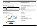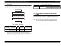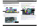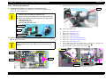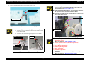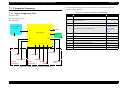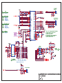
1
SERVICE MANUAL Color Inkjet Printer EPSON STYLUS CX4300/CX4400/CX5500/ CX5600/DX4400/DX4450 SEMF07-004 Notice: All rights reserved. No part of this manual may be reproduced, stored in a retrieval system, or transmitted in any form or by any means, electronic, mechanical, photocopying, recording, or otherwise, without the prior written permission of SEIKO EPSON CORPORATION. The contents of this manual are subject to change without notice. All effort have been made to ensure the accuracy of the contents of this manual. However, should any errors be detected, SEIKO EPSON would greatly appreciate being informed of them. The above not withstanding, SEIKO EPSON CORPORATION can assume no responsibility for any errors in this manual or the consequences thereof. EPSON is a registered trademark of SEIKO EPSON CORPORATION. General Notice: Other product names used herein are for identification purpose only and may be trademarks or registered trademarks of their respective owners. EPSON disclaims any and all rights in those marks. Copyright © 2007 SEIKO EPSON CORPORATION. Imaging Products CS, PL & Environmental Management PRECAUTIONS Precautionary notations throughout the text are categorized relative to 1) personal injury and 2) damage to the equipment. DANGER Signals a precaution which, if ignored, could result in serious or fatal personal injury. Great caution should be exercised in performing procedures preceded by DANGER Headings. WARNING Signals a precaution which, if ignored, could result in damage to equipment. The precautionary measures itemized below should always be observed when performing repair/maintenance procedures. DANGER 1. ALWAYS DISCONNECT THE PRODUCT FROM THE POWER SOURCE AND PERIPHERAL DEVICES PERFORMING ANY MAINTENANCE OR REPAIR PROCEDURES. 2. NO WORK SHOULD BE PERFORMED ON THE UNIT BY PERSONS UNFAMILIAR WITH BASIC SAFETY MEASURES AS DICTATED FOR ALL ELECTRONICS TECHNICIANS IN THEIR LINE OF WORK. 3. WHEN PERFORMING TESTING AS DICTATED WITHIN THIS MANUAL, DO NOT CONNECT THE UNIT TO A POWER SOURCE UNTIL INSTRUCTED TO DO SO. WHEN THE POWER SUPPLY CABLE MUST BE CONNECTED, USE EXTREME CAUTION IN WORKING ON POWER SUPPLY AND OTHER ELECTRONIC COMPONENTS. 4. WHEN DISASSEMBLING OR ASSEMBLING A PRODUCT, MAKE SURE TO WEAR GLOVES TO AVOID INJURY FROM METAL PARTS WITH SHARP EDGES. WARNING 1. REPAIRS ON EPSON PRODUCT SHOULD BE PERFORMED ONLY BY AN EPSON CERTIFIED REPAIR TECHNICIAN. 2. MAKE CERTAIN THAT THE SOURCE VOLTAGE IS THE SAME AS THE RATED VOLTAGE, LISTED ON THE SERIAL NUMBER/RATING PLATE. IF THE EPSON PRODUCT HAS A PRIMARY AC RATING DIFFERENT FROM AVAILABLE POWER SOURCE, DO NOT CONNECT IT TO THE POWER SOURCE. 3. ALWAYS VERIFY THAT THE EPSON PRODUCT HAS BEEN DISCONNECTED FROM THE POWER SOURCE BEFORE REMOVING OR REPLACING PRINTED CIRCUIT BOARDS AND/OR INDIVIDUAL CHIPS. 4. IN ORDER TO PROTECT SENSITIVE MICROPROCESSORS AND CIRCUITRY, USE STATIC DISCHARGE EQUIPMENT, SUCH AS ANTI-STATIC WRIST STRAPS, WHEN ACCESSING INTERNAL COMPONENTS. 5. REPLACE MALFUNCTIONING COMPONENTS ONLY WITH THOSE COMPONENTS BY THE MANUFACTURE; INTRODUCTION OF SECOND-SOURCE ICs OR OTHER NON-APPROVED COMPONENTS MAY DAMAGE THE PRODUCT AND VOID ANY APPLICABLE EPSON WARRANTY. 6. WHEN USING COMPRESSED AIR PRODUCTS; SUCH AS AIR DUSTER, FOR CLEANING DURING REPAIR AND MAINTENANCE, THE USE OF SUCH PRODUCTS CONTAINING FLAMMABLE GAS IS PROHIBITED. About This Manual This manual describes basic functions, theory of electrical and mechanical operations, maintenance, and repair procedures of the printer. The instructions and procedures included herein are intended for experienced repair technicians, and attention should be given to the precautions on the preceding page. Manual Configuration This manual consists of six chapters and Appendix. CHAPTER 1. PRODUCT DESCRIPTIONS Provides a general overview and specifications of the product. CHAPTER 2. OPERATING PRINCIPLES Describes the theory of electrical and mechanical operations of the product. Symbols Used in this Manual Various symbols are used throughout this manual either to provide additional information on a specific topic or to warn of possible danger present during a procedure or an action. Be aware of all symbols when they are used, and always read NOTE, CAUTION, and WARNING messages. W A R N IN G CHAPTER 3. TROUBLESHOOTING Describes the step-by-step procedures for the troubleshooting. CHAPTER 4. DISASSEMBLY / ASSEMBLY Describes the step-by-step procedures for disassembling and assembling the product. CHAPTER 5. ADJUSTMENT Provides Epson-approved methods for adjustment. CHAPTER 6. MAINTENANCE Provides preventive maintenance procedures and the list of Epsonapproved lubricants and adhesives required for servicing the product. CHAPTER 7. APPENDIX Provides the following additional information for reference: • Connector Summary • Electrical Circuits C A U T IO N C H E C K P O IN T A D J U S T M E N T R E Q U IR E D Indicates an operating or maintenance procedure, practice or condition that, if not strictly observed, could result in injury. Indicates an operating or maintenance procedure, practice, or condition that, if not strictly observed, could result in damage to, or destruction of, equipment. May indicate an operating or maintenance procedure, practice or condition that is necessary to accomplish a task efficiently. It may also provide additional information that is related to a specific subject, or comment on the results achieved through a previous action. Indicates an operating or maintenance procedure, practice or condition that is necessary to maintain the product’s quality. Indicates that a particular task must be carried out according to a certain standard after disassembly and before re-assembly, otherwise the quality of the components in question may be adversely affected. Revision Status Revision Issued Date A April 23, 2007 Description First Release EPSON Stylus CX4300/CX4400/CX5500/CX5600/DX4400/DX4450 Revision A CONTENTS Chapter 1 PRODUCT DESCRIPTION Chapter 3 TROUBLESHOOTING 1.1 Overview .............................................................................................................. 9 1.1.1 Features...................................................................................................... 9 1.2 Specifications ..................................................................................................... 10 1.2.1 Printing Specifications............................................................................. 10 1.2.2 Scanning Specifications........................................................................... 15 1.2.3 Standalone Copying Specifications ......................................................... 16 1.2.4 Electrical Specifications .......................................................................... 18 1.2.5 Environmental Conditions....................................................................... 18 1.2.6 Durability................................................................................................. 19 1.2.7 Acoustic Noise......................................................................................... 19 1.2.8 Safety approvals (Safety standards/EMI) ................................................ 19 1.2.9 Interface ................................................................................................... 19 1.2.10 Control Panel ......................................................................................... 20 1.2.11 Button Functions in Stand-alone Copy.................................................. 21 1.2.12 Errors and Panel Status.......................................................................... 21 1.2.13 Power Save Mode.................................................................................. 22 1.2.14 Nozzle Check Pattern Print ................................................................... 22 1.2.15 Printer Initialization (T.B.D) ................................................................. 22 3.1 Overview ............................................................................................................ 3.2 Error Indications and Fault Occurrence Causes ................................................. 3.3 Troubleshooting.................................................................................................. 3.3.1 Superficial Phenomenon-Based Troubleshooting ................................... Chapter 2 OPERATING PRINCIPLES 2.1 Overview ............................................................................................................ 2.2 Printer Mechanism.............................................................................................. 2.2.1 Printhead Specifications .......................................................................... 2.2.2 Carriage Mechanism................................................................................ 2.2.3 Paper Feeding Mechanism ...................................................................... 2.2.4 Ink System Mechanism ........................................................................... 2.3 Scanner Mechanism............................................................................................ 2.3.1 Scanner Carriage Mechanism.................................................................. 2.4 Electrical Circuit Operating Principles............................................................... 2.4.1 Power Supply Board................................................................................ 2.4.2 Main Board .............................................................................................. 24 24 25 25 26 27 28 28 30 30 30 33 33 37 53 Chapter 4 DISASSEMBLY/ASSEMBLY 4.1 Overview ............................................................................................................ 4.1.1 Precautions .............................................................................................. 4.1.2 Tools ........................................................................................................ 4.1.3 Work Completion Check......................................................................... 4.1.4 Caution After Repair (T.B.D).................................................................. 4.2 Disassembly Procedures..................................................................................... 4.3 Printer Section .................................................................................................... 4.3.1 Paper Support Assy. ................................................................................ 4.3.2 Stacker Assy. ........................................................................................... 4.3.3 Document Cover/ASF Cover/Support Arm ............................................ 4.3.4 Scanner Unit/Middle Case/Panel Unit .................................................... 4.4 Removing Printer Mechanism............................................................................ 4.5 Removing Board................................................................................................. 4.5.1 Main Board.............................................................................................. 4.6 Disassembling Printer Mechanism..................................................................... 4.6.1 Printhead.................................................................................................. 4.6.2 Hopper ..................................................................................................... 4.6.3 CR Scale .................................................................................................. 4.6.4 CR Motor................................................................................................. 4.6.5 CR Unit/Timing Belt ............................................................................... 4.6.6 Ink System removal................................................................................. 4.6.7 Power Supply Board................................................................................ 4.6.8 EJ Frame Assy/EJ Roller......................................................................... 4.6.9 Main Frame ............................................................................................. 4.6.10 LD Roller/ASF Unit .............................................................................. 4.6.11 Waste Ink Pads ...................................................................................... 4.6.12 PF Roller................................................................................................ 4.6.13 PF Motor................................................................................................ 61 61 61 62 63 64 65 65 65 66 67 71 73 73 75 75 78 79 80 81 83 85 86 87 90 92 93 94 6 EPSON Stylus CX4300/CX4400/CX5500/CX5600/DX4400/DX4450 Revision A 4.7 The Shortest Way to Remove the Main Frame. ................................................. 4.8 Scanner Section .................................................................................................. 4.8.1 Upper Scanner Housing........................................................................... 4.8.2 CIS Assy./CIS Carrier Assy./Scanner FFC ............................................. 4.8.3 Scanner Motor Unit/Driven Pulley.......................................................... 95 96 96 97 99 Chapter 5 ADJUSTMENT 5.1 Adjustment Items and Overview (T.B.D) ........................................................ 5.1.1 Servicing Adjustment Item List (T.B.D) ............................................... 5.1.2 Replacement Part Adjustment Items (T.B.D)........................................ 5.2 Adjustment by Using Adjustment Program (T.B.D)........................................ 5.2.1 Head angular adjustment ....................................................................... 5.2.2 Top Margin Adjustment ........................................................................ 5.2.3 Bi-D Adjustment ................................................................................... 5.2.4 First Dot Adjustment ............................................................................. 5.2.5 PF Band Adjustment.............................................................................. 101 101 103 105 105 106 106 107 107 Chapter 6 MAINTENANCE 6.1 Overview .......................................................................................................... 6.1.1 Cleaning................................................................................................. 6.1.2 Service Maintenance ............................................................................. 6.1.3 Lubrication ............................................................................................ 109 109 109 111 Chapter 7 APPENDIX 7.1 Connector Summary ......................................................................................... 7.1.1 Major Component Unit.......................................................................... 7.2 Exploded Diagram / Parts List ......................................................................... 7.3 Electrical Circuits ............................................................................................. 116 116 119 120 7 CHAPTER 1 PRODUCT DESCRIPTION EPSON Stylus CX4300/CX4400/CX5500/CX5600/DX4400/DX4450 Revision A 1.1 Overview Copy margin is automatically selected from two options, related to paper type and paper size; Standard Copy (3mm-margin), or Borderless copy. This unit provides the three primary functions; computer-connected printer, scanner, and stand-alone copy machine, and is designed for home/personal use. Its main functions are described below: Simultaneous use of functions Printer functions and scanner functions are independent and can therefore be operated simultaneously from a connected computer. 1.1.1 Features Easy-to-use control panel The control panel that has five buttons including power button and three LEDs simplifies operation. Printer functions As a printer, this unit achieves high-quality output at high speed on plain papers. It includes the following features: Maximum print resolution: 5760 (H) x 1440 (V) dpi Separate ink cartridge for each color ASF (Auto Sheet Feeder) holds up to 80 cut sheets (paper thickness: 0.11 mm) Borderless printing with EPSON special media This unit use pigment ink which is water resistant, light-fast and ozone resistant Exterior Use of a CIS sensor makes the scanner body more compact. Also, the control panel on the left side makes the printer distinctive in appearance but still easier to use. Dimension: 452 mm (W) x 347 mm (D) x 203 mm (H) (including rubber feet with Paper Support and Stacker closed) Weight: 5.0 kg (without ink cartridges) Scanner functions This unit provides scan mode so that data is scanned and transferred to a connected computer or to e-mail via application software like EPSON SMART PANEL. CIS sensor requires no warm-up period, which makes scanning more convenient and allows for a more compact scanner. Additional features include the following: Maximum optical resolution: 600 x 1200 dpi Scan gradations: 16 bits (input), 1 or 8 bits (output) Stand-alone copy functions Paper size can be selected from two or three options: Table 1-1. Paper Size Market Paper Size EAI Letter/4”x6” Europe/Asia/Pacific A4/4”x6” Latin Letter/A4/4”x6” Figure 1-1. External View Enlarge/Reduce factor can be selected from two options; actual size (100%) or “Fit to page” PRODUCT DESCRIPTION Overview 9 EPSON Stylus CX4300/CX4400/CX5500/CX5600/DX4400/DX4450 Revision A 1.2 Specifications INK CARTRIDGE SPECIFICATIONS 1.2.1 Printing Specifications The product numbers of the EPSON ink cartridges for this printer are shown below. Table 1-3. Product No. of Ink Cartridges Table 1-2. Printing Specifications Item Specification Color US Latin West Europe CISMEA Asia Print method On-demand ink jet Black T0881 T0711 T0921 T0731 T0911 Nozzle configuration Black: 90 nozzles Color: 29 nozzles x 3 (Cyan, Magenta, Yellow) T0731 T0901 Cyan T0882 T0712 T0922 T0732 T0912 Print direction Bi-directional minimum distance printing (logic seeking) T0732 T0902 Magenta T0883 T0733 T0903 T0713 T0923 T0733 T0913 Yellow T0884 T0734 T0904 T0714 T0924 T0734 T0914 Horizontal x Vertical (dpi) Print resolution Control code • • • • • 360 x 120 • 720 x 720* 360 x 360 • 1440 x 720 360 x 720* • 5760 x 1440* ESC/P Raster command EPSON Remote command Character code: Internal font (T.B.D) Font: Shelf life (T.B.D): Two years from production date (if unopened), six months after opening package. Storage Temperature Alphanumeric with expanded graphics (PC437) ASCII, 20H to 7FH only EPSON original font Alphanumeric font: Courier Table 1-4. Storage Temperature (T.B.D) Situation Input buffer size 32 Kbytes Paper feed method Friction feed, using one ASF (Auto Sheet Feeder) Paper path Top feed, front out Paper feed rates (T.B.D) • High quality mode, 19.05-mm feed 98.8 mm/sec (3.89 inch/sec) • High speed mode, continuous feed 352.8 - 6.35 mm/sec (13.89-0.25 inch/sec) PF interval Programmable in 0.017 mm (1/1440 inch) steps Note * : oC Limit oC When stored in individual boxes -30 to 40 (-22oF to 104oF) When installed in main unit -20 oC to 40 oC (-4oF to 104oF) 1 month max. at 40 oC (104oF) Dimension 12.7 mm (W) x 68 mm (D) x 47 mm (H) C A U T IO N Those resolution can only be selected in the printer driver. PRODUCT DESCRIPTION Storage Temperature Specifications The ink cartridge cannot be refilled. Do not use expired ink cartridges. The ink in the ink cartridge freezes at -16 °C (3.2 oF). It takes about three hours under 25 °C (77oF) until the ink thaws and becomes usable. 10 EPSON Stylus CX4300/CX4400/CX5500/CX5600/DX4400/DX4450 Revision A Table 1-6. Print Mode (Black) PRINT MODE Print Mode Resolution (H x V) dpi Dot Size (cps)*1 Borderless Fast Economy*2 360 x 120 Eco (360 cps) Plain Paper - Table 1-5. Print Mode (Color) Media Borderless Print Mode Resolution (H x V) dpi Dot Size (cps)*1 Fast Economy*2 360 x 120 Eco (360 cps) Plain paper - Economy 360 x 120 Eco (360 cps) Plain Paper - Economy 360 x 120 Eco (360 cps) Plain paper - Normal 360 x 360 VSD1 (165 cps) Plain Paper - Normal 360 x 360 VSD1 (165 cps) Plain paper - Fine 720 x 720 VSD2 (240 cps) Plain Paper - VSD2’ (240 cps) Photo (720) 720 x 720 VSD2 (240 cps) Matte Paper-Heavyweight OK Fine 360 x 720 (Color) 720 x 720 (Black) Best Photo (1440) 1440 x 720 VSD3 (240 cps) Matte Paper-Heavyweight OK Super Fine 360 x 720 VSD2 (240 cps) VSD3’ (240 cps) Plain paper Photo (720) 720 x 720 (Color) 1440 x 720 (Black) 720 x 720 VSD2 (240 cps) Premium Glossy Photo Paper Glossy Photo Paper Matte Paper-Heavyweight OK 1440 x 720 VSD3 (240 cps) Ultra Glossy Photo Paper Premium Glossy Photo Paper Premium SemiGloss Photo Paper Glossy Photo Paper Matte Paper-Heavyweight OK 5760 x 1440 VSD3 (240 cps) Ultra Glossy Photo Paper Premium Glossy Photo Paper Premium SemiGloss Photo Paper Glossy Photo Paper - Best Photo (1440) Photo RPM (5760) Note *1: *2: Media Plain paper Premium Glossy Photo Paper Glossy Photo Paper - OK Note *1: *2: CPS: Characters per second This mode skips a sequence to prevent paper skewing in paper loading sequences. - CPS: Characters per second This mode skips a sequence to prevent paper skewing in paper loading sequences. PRODUCT DESCRIPTION Specifications 11 EPSON Stylus CX4300/CX4400/CX5500/CX5600/DX4400/DX4450 Revision A PAPER SUPPORT The table below lists the paper type and sizes supported by the printer. The Supported paper type and sizes vary depending on destinations (between EAI, EUR, and Asia). Table 1-7. Paper Support Paper Type Plain paper Paper Size Premium Bright White Paper (EAI) Bright White Inkjet Paper (Euro, Asia) Asia P*1 B*1 P*1 B*1 - Y - Y - Letter 215.9 x 279.4 mm (8.5”x11”) Y - Y - Y - A4 210 x 297 mm (8.3”x11.7”) Y - Y - Y - B5 182 x 257 mm (7.2”x10.1”) - - Y - Y - A5 148 x 210 mm (5.8”x8.3”) - - Y - Y - 139.7 x 215.9 mm (5.5"x8.5”) Y - - - - - A6 148 x 210 mm (5.8”x8.35”) Y - Y - Y - User Defined 50.8-329 x 127-1117.6 mm (2-12.6” x 5-44”) Y - Y - Y - A4 210 x 297 mm (8.3”x11.7”) 0.11 80 g/m2 (21 lb.) - - Y - Y - 215.9 x 279.4 mm (8.5”x11”) 0.11 90 g/m2 (24 lb.) Y - - - - - 210 x 297 mm (8.3”x11.7”) 0.13 92.5 g/m2 (25 lb.) - - Y - Y - 215.9 x 279.4 mm (8.5”x11”) Y Y Y - Y - 210 x 297 mm (8.3”x11.7”) Y Y Y Y Y Y Y Y Y - Y - Y Y Y Y Y Y Letter A4 0.08-0.11 64-90 g/m2 (17-24 lb.) 8” x 10” 203.2 x 254 mm 5” x 7” 127 x 178 mm 4” x 6” 101.6 x 152.4 mm Y Y Y Y Y Y 89 x 127 mm Y Y Y Y Y Y 215.9 x 279.4 mm (8.5”x11”) Y Y Y - Y - 210 x 297 mm (8.3”x11.7”) Y Y Y Y Y Y Y Y Y - Y - Y Y Y Y Y Y Y Y Y Y Y Y 3.5” x 5” Letter A4 PRODUCT DESCRIPTION EUR B*1 Y A4 Premium Photo Paper Glossy (EAI) Premium Glossy Photo Paper (Euro, Asia) EAI P*1 215.9 x 355.6 mm (8.5”x14”) Letter Ultra Premium Glossy Photo Paper (EAI) Ultra Glossy Photo Paper (Euro, Asia) Weight Legal Half Letter Premium Inkjet Plain Paper Thickness (mm) 8” x 10” 203.2 x 254 mm 5” x 7” 127 x 178 mm 4" x 6" 101.6 x 152.4 mm 0.30 0.27 290 g/m2 (77 lb.) 255 g/m2 (68 lb.) 16:9 wide 102 x 181 mm Y Y Y Y Y Y 3.5” x 5” 89 x 127 mm Y Y Y Y Y Y Specifications 12 EPSON Stylus CX4300/CX4400/CX5500/CX5600/DX4400/DX4450 Revision A Table 1-7. Paper Support Paper Type Paper Size Letter Photo Paper Glossy (EAI) Glossy Photo Paper (Euro, Asia) Premium Photo Paper Semi-Gloss (EAI) Premium Semigloss Photo Paper (Euro, Asia) Premium Presentation Paper Matte (EAI)*1 Matte Paper-Heavyweight (Euro, Asia)*1 Envelopes Note 1: C A U T IO N A4 210 x 297 mm (8.3”x11.7”) 127 x 178 mm 4” x 6” 101.6 x 152.4 mm Letter 215.9 x 279.4 mm (8.5”x11”) 4” x 6” Letter A4 8” x 10” Weight 215.9 x 279.4 mm (8.5”x11”) 5” x 7” A4 Thickness (mm) 210 x 297 mm (8.3”x11.7”) 0.25 0.27 101.6 x 152.4 mm 215.9 x 279.4 mm (8.5”x11”) 210 x 297 mm (8.3”x11.7”) 0.23 203.2 x 254 mm #10 104.8 x 241.3 mm (4.125”x9.5”) #DL 110 x 220 mm #C6 114 x 162 mm - 258 g/m2 (68 lb.) 250 g/m2 (66 lb.) 167 g/m2 (44 lb.) 45-75 g/m2 (12-20 lb.) EAI EUR Asia P*1 B*1 P*1 B*1 P*1 B*1 Y Y Y - Y - Y Y Y Y Y Y - - Y Y Y Y Y Y Y Y Y Y Y Y Y - Y - Y Y Y Y Y Y Y Y Y Y Y Y Y Y Y - Y - Y Y Y Y Y Y - - - - - - Y - Y - Y - - - Y - Y - - - Y - Y - “Y” in the “P” column stands for “the paper type/size is Supported”. “Y” in the “B” column stands for “Borderless printing is available”. Make sure that the paper is not wrinkled, fluffed, torn, or folded. The curve of paper must be 5 mm or below. When printing onto an envelope, be sure that the flap is on the long edge and is folded. Do not use the adhesive envelopes. Do not use double envelopes and cellophane window envelopes. PRODUCT DESCRIPTION Specifications 13 EPSON Stylus CX4300/CX4400/CX5500/CX5600/DX4400/DX4450 Revision A PRINTING AREA Left margin Right margin The printing area for this printer is shown below. Top margin Table 1-8. Printing Area (Margins) Paper size Standard print Note * : Left Right Top Bottom Any size 3 mm 3 mm 3 mm 3 mm Envelope 5 mm 5 mm 3 mm 20 mm 2.54 mm* 2.54 mm* 2.96 mm* 4.02 mm* 2.82 mm* 3.60 mm* A4/Letter to 2L/5” x 7” Borderless print Margin 4” x 6”/L Printing area Paper Feed Direction Print mode The margins for Borderless print are margins that bleed off the edges of paper. Left margin Right margin Left margin Right margin Top margin Bottom margin Figure 1-3. Printing Area on Envelopes Paper Feed Direction Top margin Printing area Paper size Printing area Bottom margin Bottom margin Standard Print Borderless Print Figure 1-2. Printing Area on Cut Sheet PRODUCT DESCRIPTION Specifications 14 EPSON Stylus CX4300/CX4400/CX5500/CX5600/DX4400/DX4450 Revision A 1.2.2 Scanning Specifications SCANNING AREA Table 1-9. Scanner Specifications Table 1-10. Image Scanning Area Product type Flatbed color image scanner RW OLM RL OTM Scanning method Scanning of fixed document with mobile scan head (readable width) (out-of-range left margin) (readable length) (out-of-range top margin) Sensor CIS 216 mm (8.5”) 1.5 mm ± 1 mm 297 mm (11.7”) 1.5 mm ± 1 mm Maximum scan area 8.5” x 11.7” (216 mm x 297 mm) Document size A4 or US letter Maximum effective pixels 5,100 x 14,040 pixels (600 dpi) Resolution Main scan: Sub scan: Scanning resolution 50 to 4800 dpi (selectable in 1-dpi steps), 7200 dpi, 9600 dpi Scan area Gradations (pixel depth) Each color pixel has 16-bit input and either 1-bit or 8-bit output Scan bed Scanning speed 600 dpi Color: Monochrome: Light source RGB Three Color LED Control commands ESC/I D7 Gamma correction Two user-defined levels RL OTM 600 dpi 1200 dpi with Micro Step a Original (face down) Approx. 15 msec/line Approx. 5 msec/line RW OLM Scan direction First pixel Original's top left alignment position Figure 1-4. Image Scanning Area PRODUCT DESCRIPTION Specifications 15 EPSON Stylus CX4300/CX4400/CX5500/CX5600/DX4400/DX4450 Revision A 1.2.3 Standalone Copying Specifications COPY MODE Table 1-12. Print Mode for Copying SUPPORTED PAPER TYPES AND SIZES Copy Mode Table 1-11. Supported Paper Types and Sizes Paper Type UI Available Paper Type Mode Name Paper size Print Mode Paper Type Color copy* Plain Paper B&W copy* Plain Paper Photo copy Photo Paper Plain Paper Plain Paper Bright White Inkjet Paper (Euro/Asia) Premium Bright White Paper (EAI) A4, Letter* Premium Ink Jet Plain Paper (Euro/Asia) Photo Paper Premium Semigloss Photo Paper (Euro/Asia) Premium Photo Paper Semi-Gloss (EAI) Resolution Microweave Dot Size Fast Economy 360 x 120 dpi OFF Eco Normal 360 x 360 dpi ON VSD1 Fast Economy 360 x 120 dpi OFF Eco Normal 360 x 360 dpi ON VSD1 Best Photo 1440 x 720 dpi ON VSD3 Note* : Print mode for the Color copy and B&W copy is selectable as described below: Fast Economy: Press Color Text (or B&W Text for B&W copy) button and Stop button simultaneously. Normal: Press Color Text (or B&W Text for B&W copy) button. Glossy Photo Paper (Euro, Asia) Photo Paper Glossy (EAI) Premium Glossy Photo Paper (Euro/Asia) Premium Photo Paper Glossy (EAI) Mode Name 4” x 6” (10 x 15 cm) Ultra Glossy Photo Paper (Euro/Asia) Ultra Premium Glossy Photo Paper (EAI) Note* : EAI models: Letter size. Euro/Asia models: A4 size. Latin models: Selectable between Letter and A4. (Turning On the printer while holding down B&W Copy Start button selects Letter size, and turning On the printer while holding down Color Copy Start button selects A4 size.) Table 1-13. Copy Mode (Enlarging/Reducing) Copy Button Copy Mode Enlarge/ Reduce Margins Description B&W Text Color Text Standard 100% 3 mm Copies A4/Letter original to the same size Standard Fit to page 3 mm Enlarges or reduces to A4/Letter Borderless Fit to page 0 mm Enlarges or reduces to 4" x 6"/L size Color Photo Note* : “Fit to page” automatically sets the enlarge/reduce scale. When an original is smaller than general card size (approx. 54mm x 86mm), the margins will be different from those shown in the table. COPY SPEED Table 1-14. Copy Speed UI Paper Type Plain Paper (A4/Letter) Photo Paper (4” x 6”) Note *1: *2: PRODUCT DESCRIPTION Specifications Print Mode Black Color Fast Economy 5 sec.*1 14 sec.*1 Normal 20 sec.*1 72 sec.*1 - 380 sec.*2 Best Photo When printing “e-memo Pattern” on Plain Paper. Borderless printing 16 EPSON Stylus CX4300/CX4400/CX5500/CX5600/DX4400/DX4450 Revision A COPY AREA BORDERLESS COPY The following table shows the relative positioning of the original and copy. The following table shows the relative positioning of the original and copy. Table 1-15. Original (scanner) Table 1-17. Original (scanner) RW OLM RL OTM RW OLM RL OTM (readable width) (out-of-range left margin) (readable length) (out-of-range top margin) (readable width) (out-of-range left margin) (readable length) (out-of-range top margin) 216 mm (8.5”) 3 mm 297 mm (11.7”) 3 mm 216 mm (8.5”) 1.5 mm ± 1 mm 297 mm (11.7”) 1.5 mm ± 1 mm Table 1-16. Copy (printer) Table 1-18. Copy (printer) RM LM TM BM RO LO TO BO 3 mm (0.12”) 3 mm (0.12”) 3 mm (0.12”) 3 mm (0.12”) 2.5 mm 2.5 mm 2.8 mm 3.6 mm RL RL OTM OTM a Scan area Original (face down) RW RW Scan direction Print area Top left corner of the original LO Top left corner of the original PW PW Original (face down) Start point a a Copy paper Scan area Print direction Scan direction Start point LM Scan bed OLM OLM Print direction Right side of original a Right side of original Scan bed Print area Copy paper Copy Copy Right side of copy Right side of copy RM BM RO TM PL PL Figure 1-5. Standard Copy PRODUCT DESCRIPTION TO BO Figure 1-6. Borderless Copy Specifications 17 EPSON Stylus CX4300/CX4400/CX5500/CX5600/DX4400/DX4450 Revision A 1.2.4 Electrical Specifications 1.2.5 Environmental Conditions Primary power input Table 1-20. Environmental Performance Table 1-19. Primary Power Input Item 100-120 V model 220-240 V model Rated power supply voltage 100 to 120 VAC 220 to 240 VAC Input voltage range 90 to 132 VAC 198 to 264 VAC Rated current 0.6A (max. 0.7) 0.3A (max. 0.4) Rated frequency Energy conservation Printing Humidity*2 Operating 10 to 35°C (50 to 95°F) 20 to 80%*3 Transporting*1 -20 to 60°C*3 (-4°F to 140°F) 5 to 85% 49.5 to 60.5 Hz No condensation 1500 ACVrms for one minute *3: 120 hours at 60°C, One month at 40°C International Energy Star Program compliant 17.9 W 17.7 W 80 Copying (normal BK mode) 15.3 W 15.6 W 70 Copying (draft BK mode) 21.6 W 22.0 W 10.5 - 13.6 W 10.5 - 14.1 W 3.8 W 3.8 W 1W 1W (color draft on plain paper) Scanning Sleep mode Standby mode (power-off) Vibration 1G 0.15G (1 msec or less) (X,Y,Z directions) 2G 1.5G (2 msec or less) (X,Y,Z directions) Note : The combined Temperature and Humidity conditions must be within the blue-shaded range shown below. 13.8 W Printing Shock Packed in the original package *2: 13.3 W (black text on plain paper) Power consumption Temperature Note *1: 50 to 60 Hz Input frequency range Dielectric strength Condition 90 Humidity (%) 60 50 40 30 Note 1: If the printer is not operated for more than five minutes (T.B.D.), the standby function reduces the current to the motor to conserve power. 2: If the scanner is not operated for more than five minutes (T.B.D.), the standby function reduces the current to the motor to conserve power. 3: If the control panel is not operated for more than thirteen minutes (T.B.D.), the control panel turns to the power save mode within fifteen minutes (T.B.D.). 20 27/80 10/50 20/68 30/86 35/95 40/104 Temperature (°C/°F) Figure 1-7. Temperature/Humidity Range PRODUCT DESCRIPTION Specifications 18 EPSON Stylus CX4300/CX4400/CX5500/CX5600/DX4400/DX4450 Revision A 1.2.6 Durability 1.2.9 Interface Total print life: 10,000 pages (black only, A4), or three years (whichever comes first) Printhead life: Seven billion shots (per nozzle) or five years (whichever comes first) Scanner head: 36,000 cycles (MCBF) The printer has a USB interface of the following specification. Standards 1.2.7 Acoustic Noise Maximum 47 dB (printing ECMA pattern on Premium Glossy Photo Paper in Best Photo mode) 1.2.8 Safety approvals (Safety standards/EMI) USA Canada Mexico Taiwan EU Germany Russia Singapore Korea Hong Kong Argentina Australia PRODUCT DESCRIPTION UL60950-1 FCC Part15 Subpart B Class B CAN/CSA-C22.2 No.60950-1 CAN/CSA-CEI/IEC CISPR 22 Class B NOM-019-SCFI-1998 CNS13438 Class B CNS14336 EN60950-1 EN55022 Class B EN61000-3-2, EN61000-3-3 EN55024 EN60950-1 GOST-R (IEC60950-1, CISPR 22) IEC60950-1 K60950-1 KN22 Class B KN61000-4-2/-3/-4/-5/-6/-11 IEC60950-1 IEC60950-1 AS/NZS CISPR22 Class B “Universal Serial Bus Specifications Revision 2.0” “Universal Serial Bus Device Class Definition for Printing Devices Version 1.1” (printer unit) Transfer rate: 12 Mbps (Full Speed Device) Data format: NRZI Compatible connector: USB Series B Recommended cable length: 2 [m] or less Device ID Table 1-21. Device ID (T.B.D) Product Name Device ID CX4300 [00H][60H] MFG:EPSON; CMD:ESCPL2,BDC,D4,ESCPR1; MDL:Stylus[SP]CX4300; CLS:PRINTER; DES:EPSON[SP]Stylus[SP]CX4300; CX4400 [00H][60H] MFG:EPSON; CMD:ESCPL2,BDC,D4,ESCPR1; MDL:Stylus[SP]CX4400; CLS:PRINTER; DES:EPSON[SP]Stylus[SP]CX4400; CX5500 [00H][60H] MFG:EPSON; CMD:ESCPL2,BDC,D4,ESCPR1; MDL:Stylus[SP]CX5500; CLS:PRINTER; DES:EPSON[SP]Stylus[SP]CX5500; Specifications Product Name Device ID CX5600 [00H][60H] MFG:EPSON; CMD:ESCPL2,BDC,D4,ESCPR1; MDL:Stylus[SP]CX5600; CLS:PRINTER; DES:EPSON[SP]Stylus[SP]CX5600; DX4400 DX4450 [00H][60H] MFG:EPSON; CMD:ESCPL2,BDC,D4,ESCPR1; MDL:Stylus[SP]DX4400; CLS:PRINTER; DES:EPSON[SP]Stylus[SP]DX4400; 19 EPSON Stylus CX4300/CX4400/CX5500/CX5600/DX4400/DX4450 Revision A 1.2.10 Control Panel BUTTONS The five buttons on the control panel functions as shown below. Table 1-22. Buttons Button Function Power Turns the power on or off. Stop • Job cancel • Head cleaning • Ink Cartridge replacement Color Photo • Photo copy • Recovery from an error state B&W Text • B&W copy (100% scale with 3 mm margins, or Fit to page) • Recovery from an error state Color Text • Color copy (100% scale with 3 mm margins, or Fit to page) • Recovery from an error state Note * : Power LED Power Button Ink LED Paper LED Stop Button See “1.2.11 Button Functions in Stand-alone Copy” (p.21) for more details. INDICATORS (LED) Color Photo Button The three LEDs on the control panel indicates printer status as shown below. B&W Text Button Table 1-23. Indicators (LEDs) LED Function Power LED [Green] *1 Flashes during power-on and power-off sequence. Flashes during some operation (printing, scanning, copying or cleaning) is in process. Lights at stand-by. Ink LED [Orange] Flashes or lights to indicate an ink-related status or error.*2 Paper LED [Orange] Flashes or lights to indicate a paper-related status or error.*2 Note *1: *2: All LEDs except for Power LED will be turned off while printing or scanning by a computer. See “1.2.12 Errors and Panel Status” (p.21) for more details. PRODUCT DESCRIPTION Color Text Button Figure 1-8. Control Panel Note : Figure 1-8 is the control panel of the model for US/ESP/EAL. The button names or other indications printed on the panel differ depending on the destination. Specifications 20 EPSON Stylus CX4300/CX4400/CX5500/CX5600/DX4400/DX4450 Revision A 1.2.11 Button Functions in Stand-alone Copy Table 1-24. Buttons The functions of the buttons in stand-alone copy mode are described in the table below. Table 1-24. Buttons Button Function Power Turns the power on or off. Stop • Job cancel Cancels a print or copy job, and ejects paper if paper has been fed inside. • Head cleaning Runs a head cleaning cycle when pressed for three seconds or longer. If there is not enough ink for the cleaning, the cleaning is automatically cancelled and the printer indicates Ink out error. • Ink Cartridge replacement Moves the carriage to the position for replacing an ink cartridge(s) when pressed during Ink out error or No ink cartridge error. Starts ink charging when pressed after replacing the ink cartridge(s). Color Photo B&W Text Color Text B&W Text + Stop • Photo copy Makes a color copy on 4x6 or L-sized Photo Paper. • Recovery from an error state Executes the remaining job when pressed after the error cause is removed. • B&W copy (100% scale with 3 mm margins) Makes a B&W copy on A4 or Letter-sized Plain Paper. • B&W copy (Fit to page) When pressed for three seconds or longer, makes a B&W copy on A4 or Letter-sized Plain Paper enlarging or reducing the original image to fit it to the paper size. • Recovery from an error state Executes the remaining job when pressed after the error cause is removed. • Color copy (100% scale with 3 mm margins) Makes a color copy on A4 or Letter-sized Plain Paper. • Color copy (Fit to page) When pressed for three seconds or longer, makes a color copy on A4 or Letter-sized Plain Paper enlarging or reducing the original image to fit it to the paper size. • Recovery from an error state Executes the remaining job when pressed after the error cause is removed. Makes a B&W copy on A4 or Letter-sized Plain Paper in Fast Economy print mode. (100% scale with 3 mm margins) PRODUCT DESCRIPTION Button Function Color Text + Stop Makes a color copy on A4 or Letter-sized Plain Paper in Fast Economy print mode. (100% scale with 3 mm margins) B&W Text + Power (Only for Latin models) Selects Letter size for B&W and Color copy. Color Text + Power (Only for Latin models) Selects A4 size for B&W and Color copy. 1.2.12 Errors and Panel Status Table 1-25. Errors and Panel Status Error LED status Cause Recovery Priority Mechanical trouble Turn the power Off. Remove the cause and turn the power back on. If the error still occurs, call service. 1 All LEDs lights Some internal part needs to be replaced Call service. 2 Paper LED flashes A paper jam has occurred Remove the paper and press B&W or Color Text button to continue, or press Stop button to cancel the job. 3 Paper out Paper LED lights Load paper on the ASF correctly, and press B&W or Failed to load the paper. Color Text button to continue, or press Stop button to cancel the job. 3 Ink out Ink LED lights Some cartridge has run Replace the cartridge with out of ink. EPSON genuine one. 4 No Ink Cartridge Ink LED lights Some cartridge was not Replace the cartridge with detected. EPSON genuine one. 4 Incorrect Ink Cartridge Ink LED lights An incorrect cartridge was detected. 4 Fatal error All LEDs flash Maintenance request Paper jam Note * : Specifications Replace the cartridge with EPSON genuine one. When two or more errors occur at the same time, the one with higher priority will be indicated. 21 EPSON Stylus CX4300/CX4400/CX5500/CX5600/DX4400/DX4450 Revision A 1.2.13 Power Save Mode 1.2.15 Printer Initialization (T.B.D) Without any panel operation for 15 minutes (T.B.D.) while the printer and scanner unit are in standby status, this unit moves into the low power panel mode in which power consumption for the panel decreases. This unit recovers from that mode by pushing any button but Power Button or printing/ scanning by the computer. This unit is turned off by pushing Power Button in that mode. There are four kinds of initialization method, and the following explains each initialization. 1. Power-on initialization This printer is initialized when turning the printer power on, or printer recognized the cold-reset command (remote RS command). When printer is initialized, the following actions are performed. (a) Initializes printer mechanism (b) Clears input data buffer (c) Clears print buffer (d) Sets default values 2. Operator initialization This printer is initialized when turning the printer power on again within 10 seconds from last power off, or printer recognized the -INIT signal (negative pulse) of parallel interface. When printer is initialized, the following actions are performed. (a) Cap the printer head (b) Eject a paper (c) Clears input data buffer (d) Clears print buffer (e) Sets default values 3. Software initialization The ESC@ command also initialize the printer. When printer is initialized, the following actions are performed. (a) Clears print buffer (b) Sets default values 4. Power-on initialization except I/F The printer recognized the IEEE 1284.4 “rs” command. When printer is initialized, the following action is performed. (a) Initializes printer mechanism (b) Clears input data buffer (c) Clears print buffer (d) Sets default values except I/F Table 1-26. Power Save Mode Action Function Transition to power save mode Turn off all the LEDs except for Power LED. Recovery from power save mode Recall the panel status as that before moving to low power panel mode. 1.2.14 Nozzle Check Pattern Print Nozzle check pattern can be printed only with this unit. Left ink quantity of each color is also printed in 10% increments. To activate this function, turn on this unit while depressing Ink Button. After printing the pattern, this unit moves to ordinary standby status. The example of nozzle check pattern is explained below. 1 <Black> 1 <Yellow> 1 <Magenta> 31 30 61 60 1 <Cyan> 29 29 90 360dpi VSD1 29 0.212mm (1/120inch) 8 dots Figure 1-9. Nozzle check pattern PRODUCT DESCRIPTION Specifications 22 CHAPTER 2 OPERATING PRINCIPLES EPSON Stylus CX4300/CX4400/CX5500/CX5600/DX4400/DX4450 Revision A 2.1 Overview This section describes the operating principles of the Printer Mechanism, Scanner Mechanism and Electrical Circuit Boards. PF roller PF motor 2.2 Printer Mechanism Star wheel rollers Printer mechanism of Stylus CX4300/CX4400/CX5500/CX5600/DX4400/DX4450 consists of printhead, carriage mechanism, paper loading/feeding mechanism, and ink system. As in the case of conventional models, Stylus CX4300/CX4400/CX5500/CX5600/ DX4400/DX4450 has two motors; one is a stepping motor for paper loading/feeding mechanism, and the other is a DC motor for carriage mechanism. Papers are fed from the backside and ejected from the front side of the printer. Paper feeding mechanism feeds papers using the LD roller and the retard roller. CR timing belt CR encoder sensor Carriage unit Retard roller Compression spring LD roller PE sensor Paper eject roller Cam, large Cam, small CR lock lever Clutch Pump unit Cap unit CR motor Figure 2-1. Printer Mechanism Outline OPERATING PRINCIPLES Overview 24 EPSON Stylus CX4300/CX4400/CX5500/CX5600/DX4400/DX4450 Revision A 2.2.1 Printhead Specifications 2.2.2 Carriage Mechanism The Printhead of this product is a D2-CHIPS type. Main components of the carriage mechanism are carriage unit (including printhead, CR encoder sensor), CR motor, timing belt, and CR scale. Nozzle configuration 2.2.2.1 CR Motor Specifications Monochrome 90 nozzles Color 29 nozzles x 3 (Cyan, Magenta, Yellow) Table 2-1. CR Motor Specifications The following shows the arrangement of the nozzles and the color arrangement of each nozzle line when viewed the printhead from behind. Item Specification Type Motor with DC brush Drive voltage 2.822mm (40/360 inch) Electric resistance Inductance K#90 C#29 K#89 +42 V ± 5% (applied voltage to the driver) 28.8 Ω ± 10% 20.1 mH ± 25% Drive method PWM, constant-current chopping Drive IC A6628 Cyan: 29nozzles C#1 Magenta: 29nozzles Black Color M#29 Paper Loading Direction M#1 Y#29 Yellow: 29nozzles Y#3 Y#2 K#3 Y#1 K#2 0.2117mm (1/120 inch) K#1 Carriage Moving Direction Figure 2-2. Nozzle Rear View OPERATING PRINCIPLES Printer Mechanism 25 EPSON Stylus CX4300/CX4400/CX5500/CX5600/DX4400/DX4450 Revision A 2.2.3 Paper Feeding Mechanism 2.2.3.2 Drive Process Paper loading/feeding mechanism consist of CR lock lever inside the ink system, LD roller shaft (including clutch mechanism), and ASF unit. 1. CR lock lever and clutch mechanism play an important role in paper loading mechanism. Refer to 2.2.3.2 Drive Process (p26) for details. Drive of the PF motor is always transmitted to the paper eject roller and the PF roller, however, it is not transmitted to the LD roller and the retard roller owing to the clutch of the LD roller shaft. 2. The carriage unit moves to the ASF trigger position once the paper loading command is received. 2.2.3.1 PF Motor Specifications (For both ASF and Pump motor) 3. PF motor is rotated counter clockwise, and the clutch is released by the CR lock lever. 4. After the clutch is released, the PF motor rotates clockwise. Drive is transmitted to the LD roller and the paper loading operation begins. 5. During paper loading operation, papers are fed from the ASF unit to inside the printer by the rotating movement of the two cams of the LD roller. Table 2-2. PF Motor Specification Item Specification Type 4-phase, 48-pole PM stepping motor ± 5% (applied voltage to the driver) Drive voltage +42 V Wire wound resistance 4.3 Ω +8 / -12% (per one phase at 20 °C) Cam, large:releases hopper Inductance 5.5 mH ± 20% (1KH, 1Vrms) Cam, small:releases paper back lever Drive method Bipolar drive 2-2 phase, 1-2 phase, W1-2phase, 2W1-2phase, 4W1-2 phase constant-current drive Drive IC A6628 OPERATING PRINCIPLES 6. Once a sheet of paper is fed, the hopper and the paper back lever bring back rest of the papers to the position in readiness by the rotating movement of the two cams mentioned above. 7. When the LD roller is turned a full circle, the CR lock lever release the clutch and the drive to the LD roller is interfered. Printer Mechanism 26 EPSON Stylus CX4300/CX4400/CX5500/CX5600/DX4400/DX4450 Revision A 2.2.4 Ink System Mechanism The Ink system mechanism consists of pump mechanism and capping mechanism that includes wiper mechanism. 2.2.4.1 Pump Unit Mechanism When the PF motor turns, power is always transmitted to the ink system. Table 2-3. PF Motor Rotational Direction & Ink System Mechanism Direction* Counterclockwise Clockwise Note * : Function Absorbs the ink by the Pump Unit Release pump. The PF Motor rotational direction = seen from the left side of the printer. 2.2.4.2 Capping Mechanism The Capping mechanism covers the printhead with the cap to prevent the nozzle from increasing viscosity when the printer is in stand-by state or when the printer is off. OPERATING PRINCIPLES Printer Mechanism 27 EPSON Stylus CX4300/CX4400/CX5500/CX5600/DX4400/DX4450 Revision A 2.3 Scanner Mechanism Scanner Carriage Shaft Scanner Carriage Unit The Scanner Mechanism of Stylus CX4300/CX4400/CX5500/CX5600/DX4400/ DX4450 are constructed of a Scanner Carriage Unit, Scanner Motor, etc., in the same way as previous A4 size scanners. 2.3.1 Scanner Carriage Mechanism 2.3.1.1 Scanner Carriage Unit Overview The Scanner Carriage Unit consists of a CIS Board, Rod Lens Array, LEDs, etc. CIS Board CIS Board contains the sensing elements that are placed across the entire width of an original. The sensing elements, which does not install a color filter, read an original through the Rod Lens Array by turning on red, green, and blue lightemitting diodes (LEDs) alternately. It is not the CIS Board but the Main Board that converts the analog light signal read by the Rod Lens Array into digital signal. Rod Lens Array A number of rod-shaped lenses, which are arranged on the sensing elements, are also placed across the entire width of an original. These lenses read the light reflected from the original that is produced by the light source (LEDs) and pass the information to the sensing elements. Compared to conventional CCD method, this optical system allows the focal length (distance between sensor and image scanned) to be shallow. Therefore, an original to be scanned should be brought close to the document glass. The optical system, in addition, is 1:1, (there is no optical reduction or enlargement) and this results in a scanner offering the solid performance in terms of accuracy. Scanner Motor Figure 2-3. Scanner Mechanism Rod Lens Array LED CIS LED Stylus CX4300/CX4400/CX5500/CX5600/DX4400/DX4450 use three color LEDs (the three colors being red, green, and blue) to illuminate the line to be scanned in the document. Unlike cold cathode fluorescent lamp used in CCD method, usage of LEDs requires no warm-up time and allows the CIS to be highly power efficient. OPERATING PRINCIPLES Timing Belt Scanner Mechanism Scanner Carriage Unit CIS Board Figure 2-4. Scanning image 28 EPSON Stylus CX4300/CX4400/CX5500/CX5600/DX4400/DX4450 Revision A 2.3.1.2 Scanner Carriage Unit Movement Overview Image is scanned in the main scanning direction (=1 line) by the CIS board and in the sub-scanning direction (=several lines) combined with Scanner Carriage Unit movement. (See the figure below.) The CIS board can scan 1 line in main scanning direction (parallel to the Scanner Carriage Unit) at one time. When scanning next lines after the second line in subscanning direction, CR driving moves the Scanner Carriage Unit, and scan the lines. The scanned data is sent to the control board. The scanned data for “n” lines and “n-1” line are processed consecutively. 1st line 2nd line Document Drive of the Scanner Motor is transferred to the Scanner Carriage Unit by the Scanner Timing Belt. The Scanner Carriage Unit slides in the secondary scanning direction. The Scanner Motor uses a stepping motor and drives using open loop control. Left side Scanner Motor 1 pixel Mainscanning direction Scanner Carriage Unit Right side Scanner Carriage Unit Sub-scanning direction by Scanner Carriage Unit movement Figure 2-6. Scanner Carriage Unit Mechanism Figure 2-5. Scanner Carriage Unit movement The table below shows the specifications for the stepping motor that controls the Scanner Carriage Mechanism. Table 2-4. Scanner Motor specifications Item Description Motor type PM type stepping motor Drive voltage 42V (DC) Coil resistance 37Ω ±10% (per phase at 25 degrees) Inductance TBDmH ± TBD% Driving method PWM Driver IC L6219 OPERATING PRINCIPLES Scanner Mechanism 29 EPSON Stylus CX4300/CX4400/CX5500/CX5600/DX4400/DX4450 2.4 Electrical Circuit Operating Principles The electric circuit of Stylus CX4300/CX4400/CX5500/CX5600/DX4400/DX4450 consists of the following boards: Main board: PCBA MB Power supply board: ASSY POWER 110V/220V Panel board: PCBA PB Panel Board PF Motor Head Driver Board The logic circuit of the Main Board is composed of the following: Printer Mechanism Sensors Scanner Motor CIS Assy. Scanner Mechanism +42VDC Power Supply Board Figure 2-7. Electrical Circuit Block Diagram OPERATING PRINCIPLES In the Power Supply Board of Stylus CX4300/CX4400/CX5500/CX5600/DX4400/ DX4450, the simulated oscillating stimulation flyback converter circuit method is used, and it supplies +42 VDC to the drive line. The application of the output voltage is described below. 2.4.2 Main Board CR Motor Power Off 2.4.1 Power Supply Board AC voltage input from AC inlet first goes through filter circuit that removes high frequency components and is then converted to DC voltage via the rectifier circuit and the smoothing circuit. DC voltage is then led to the switching circuit and FET QF1 preforms the switching operation. By the switching operation of the primary circuit, +42VDC is generated and stabilized at the secondary circuit. The figure below shows the block diagram of this printer. Main Board Revision A Logic line (CPU-ASIC 4 in 1, Flash-ROM and so on) Motor control/drive circuit (CR Motor, PF Motor, Scanner Motor) Head control/drive circuit USB I/F circuit Sensor circuit Reset circuit, EEPROM circuit Table 2-5. Main Board Major Components and Primary Functions IC Location CPU-ASIC U3 Drives CPU (H8S/2674 base), internal 8 K byte x 4 RAM, 24 Mhz, 3.3 V/1.8V SDRAM U4 3.3 V drive 4M x 16 bit DRAM Serial Flash U5 3.3 V drive 4 M bit Serial Flash that stores the program U6 Scanner motor drive; adjusts 5 V, drives 42 V U7 CR/PF motor drive; adjusts 5 V, drives 42 V • EEPROM Default settings, backup for all parameters • Reset function • Timer function Generates trapezoidal waveform, drives 3.3 V Motor Driver RTC U9 DAC U10 Electrical Circuit Operating Principles Function 30 EPSON Stylus CX4300/CX4400/CX5500/CX5600/DX4400/DX4450 Revision A Serial Flash (U5) RTC (U9) SDRAM (U4) CIS Assy. J5 Panel Board J3 J7 CR Motor Motor Driver (U7) J8 PF Motor Motor Driver (U6) J6 Scanner Motor J9 PE Sensor CN1 Printhead CPU-ASIC (U3) Data Address DAC (U10) Q12, Q13 USB (J2) Power Supply Board CN2 CR Encoder Sensor J1 CSIC Board Figure 2-8. Main Board Block Diagram OPERATING PRINCIPLES Electrical Circuit Operating Principles 31 CHAPTER 3 TROUBLESHOOTING EPSON Stylus CX4300/CX4400/CX5500/CX5600/DX4400/DX4450 Revision A 3.1 Overview Table 3-2. Sensor check point Sensor name This chapter describes unit-level troubleshooting. Refer to the flowchart in this chapter to identify the defective unit and perform component level repair if necessary. This chapter also explains motor coil resistance, sensor specification and error indication. PE Sensor Check point J9 / Pin 1 and 2 Signal level Switch mode Less than 0.4V Off: No paper More than 2.4V On : Detect the paper START 3.2 Error Indications and Fault Occurrence Causes Unit-level troubleshooting Unit repair This section describes the LED indications, STM3 messages and fault occurrence causes at occurrence of the following errors during any sequence/operation (e.g. power-on sequence, paper feeding/loading sequence, ink sucking sequence). Assemble & Adjustment NOTE: The STM3 windows shown in the table in the following pages are the ones of Stylus CX4300/CX4400/CX5500/CX5600/DX4400/DX4450, however, other models show almost the same displays as those except the following items: 1) Printer model name 2) T-code for each ink cartridge (refer to Table 1-3 (p.10) ) END Figure 3-1. Troubleshooting flowchart Table 3-1. Motor, coil resistance Motor Motor Type Location Check point Resistance Scanner motor Stepping motor J6 Pin 1 and 3 Pin 2 and 4 37Ω ± 10% (T.B.D.) PF motor 4-phase, 48-pole, PM Stepping motor J8 Pin 1 and 3 Pin 2 and 4 4.3Ω+8/-12% (20°C) Note : The CR motor is DC motor. Since the resistance of the DC motor varies among the electric poles, resistance value cannot be used to check the DC motor. When a malfunction of the CR motor is suspected, check the motor if it moves normally or not. However, it is difficult to judge accurately, if it is not clear, replace the motor. TROUBLESHOOTING Overview 33 EPSON Stylus CX4300/CX4400/CX5500/CX5600/DX4400/DX4450 Revision A Table 3-3. Error Indications and Fault Occurrence Causes Communication Error Ink Low Double Feed Paper Out Power — — — — Ink — — — — Paper — — — On This error is detected at resending of paper for double-sided printing when paper length is determined to be other than default value. This error is detected when the top of a paper is not detected with the PE Sensor in the paper loading sequence. Table 3-8, “Check point for double feed error according to each phenomenon,” on page 39 Table 3-9, “Check point for paper out error according to each phenomenon,” on page 40 Indications Printer Status Status monitor 3 message Fault Occurrence Cause Reference Page Note : “–” This error is detected when the SPC cannot communicate with the PC correctly. Table 3-6, “Check point for communication error according to each phenomenon,” on page 37 This error is detected when the ink consumption amount reaches about 90%. Note : Even if this error is indicated on the STM3, you can continue printing until I/C becomes Replace Ink Cartridge condition. However, the Head Cleaning operation cannot be done so that the remaining ink is low condition. --- : No change TROUBLESHOOTING Error Indications and Fault Occurrence Causes 34 EPSON Stylus CX4300/CX4400/CX5500/CX5600/DX4400/DX4450 Revision A Table 3-4. Error Indications and Fault Occurrence Causes Replace Ink Cartridge or No Ink Cartridge CSIC Error Incorrect I/C Paper Jam Power — — — — Ink On On On — Paper — — — On Indications Printer Status Status monitor 3 message Fault Occurrence Cause Reference Page Note : “–” This error is detected when; • The ink consumption amount reaches 100%. • The ink cartridge is defective. This error is detected when data from CSIC cannot be read normally or when data cannot be written to CSIC. This error is detected when; • An unsupported ink cartridge has been installed. • An ink cartridge with a different destination has been installed. This error is detected when the PE Sensor cannot properly detect the paper bottom edge during feeding of paper. Table 3-10, “Check point for no ink cartridge/CSIC error/incorrect ink cartridge according to each phenomenon,” on page 43 Table 3-10, “Check point for no ink cartridge/CSIC error/incorrect ink cartridge according to each phenomenon,” on page 43 Table 3-11, “Check point for paper jam error according to each phenomenon,” on page 44 Note : The slight amount of the ink is remaining in the I/C even if the Replace Ink Cartridge error is detected. This is to prevent the Print Head nozzle from the printing operation without firing the ink. Table 3-10, “Check point for no ink cartridge/CSIC error/incorrect ink cartridge according to each phenomenon,” on page 43 : No change TROUBLESHOOTING Error Indications and Fault Occurrence Causes 35 EPSON Stylus CX4300/CX4400/CX5500/CX5600/DX4400/DX4450 Revision A Table 3-5. Error Indications and Fault Occurrence Causes Maintenance Request Fatal Error (Mechanism) Power On Blink Ink On Blink Paper On Blink This error is detected when the Waste Ink Counter exceeds the preset counter value. This error is detected when it is determined that the printer cannot operate properly. (CR error, PF error, etc.) “5.2.3 Waste Ink Pad Counter” (p.XXX) (T.B.D.). Table 3-12, “Check point for fatal error according to each phenomenon,” on page 47 Indications Printer Status Status monitor 3 message Fault Occurrence Cause Reference Page TROUBLESHOOTING Error Indications and Fault Occurrence Causes 36 EPSON Stylus CX4300/CX4400/CX5500/CX5600/DX4400/DX4450 Revision A 3.3 Troubleshooting You can identify the troubles by using the checklist in this section after confirming the LED indication on the SPC. If you connect the SPC to your PC and see an error message on the STM3, you can short the total repair time. And, when you find out the defective parts, replace them by referring the Chapter 4 “DISASSEMBLY AND ASSEMBLY”. The following tables describe the error check points. Table 3-6. Check point for communication error according to each phenomenon Occurrence timing CR position • Power on • Anywhere Detailed phenomenon When turning on the power, the SPC does not operate at all. Defective unit/part name Panel Unit Check point 1. Check if the Panel Board is not damaged. 1. Replace the Panel Board with new one. 1. Check if the PS Board Connector Cable is connected to the J1 on the Main Board. 1. Connect the PS Board Connector Cable to J1 on the Main Board. Main Board • Power on • Anywhere When turning on the power, the SPC does not operate at all. PS Board Unit Remedy J1 2. Check if the PS Board Connector Cable/PS Board is not damaged. 2. Replace the PS Board Unit with new one. * If the problem is not solved, replace the Main Board with new one. PS Board Connector Cable PS Board Unit TROUBLESHOOTING Troubleshooting 37 EPSON Stylus CX4300/CX4400/CX5500/CX5600/DX4400/DX4450 Revision A Table 3-6. Check point for communication error according to each phenomenon Occurrence timing CR position Detailed phenomenon Defective unit/part name USB Cable • Operation • – When turning on the power, the power on sequence is performed correctly. But, when any printer job is sent to the SPC, a communication error is indicated with STM3. Check point Remedy 1. Check if the USB Cable is connected between the SPC and the PC. 1. Connect the USB Cable to the SPC and the PC. 1. Check if an incorrect model name is not stored into the address of the EEPROM on the Main Board. 1. Use the Adjustment Program to write the correct value to the EEPROM address. 2. Check if the Panel FFC is connected to the J3 on the Main Board. 2. Connect the Panel FFC to the J3 on the Main Board. Main Board Main Board Unit Panel FFC J3 Table 3-7. Check point for error before the initial ink charge according to each phenomenon Occurrence timing CR position • Power on • Inside HP • Power on • Anywhere Detailed phenomenon The SPC does not perform the initial ink charge and an error is indicated with LEDs and STM3. The SPC does not perform the ink replacement CL and an error is indicated with LEDs and STM3. The SPC does not perform the printing operation and an error is indicated with LEDs and STM3. TROUBLESHOOTING Defective unit/part name Check point Remedy Ink Cartridge 1. Check if the Ink Cartridge can be used by installing it to other SPC. 1. Replace the Ink Cartridge with a brand-new one. Main Board 1. Check if an incorrect data is not stored into the address of the EEPROM on the Main Board. 1. Set the proper destination by using Adjustment Program. 1. Check if the Ink Cartridge can be used by installing it to other SPC. 1. Replace the Ink Cartridge with a brand-new one. 1. Check if the ink is remaining in the Ink Cartridge. 1. Replace the Ink Cartridge with a brand-new one. 2. Check if the Ink Cartridge can be used by installing it to other SPC. 2. Replace the Ink Cartridge with a brand-new one. Ink Cartridge Ink Cartridge Troubleshooting 38 EPSON Stylus CX4300/CX4400/CX5500/CX5600/DX4400/DX4450 Revision A Table 3-8. Check point for double feed error according to each phenomenon Occurrence timing CR position Detailed phenomenon Defective unit/part name Check point 1. Check if the Extension Spring Retard operates correctly in the paper loading sequence. Remedy 1. Set the Extension Spring Retard between the Retard Roller Unit and the ASF Frame. Back side of ASF Unit • Operation • – After both surfaces were printed, the paper was ejected but an error is displayed. Extension Spring Retard ASF Unit 2. Check if the Paper Back Lever operates correctly in the paper loading sequence. Back side of ASF Unit 2. Set the Torsion Spring 6.45 between the ASF Frame and the Paper Back Lever. Torsion Spring 6.45 Paper Back Lever TROUBLESHOOTING Troubleshooting 39 EPSON Stylus CX4300/CX4400/CX5500/CX5600/DX4400/DX4450 Revision A Table 3-9. Check point for paper out error according to each phenomenon Occurrence timing CR position Detailed phenomenon Defective unit/part name Check point Remedy 1. Check if any paper dust is not adhered to the surface of the LD Roller. • Operation • – The LD Roller cannot pick up paper although the LD Roller attempt to rotate correctly. LD Roller 1. Set a cleaning sheet in the ASF Unit up side down. Then holding the top edge, try to load the paper from the Printer driver. The micro pearl on the LD Roller surface is removed. To remove severe smear, staple a cloth moistened with alcohol to a post card and clean the roller in the same manner. Non-adhesive Area (Use a post card for the base sheet) CL Sheet Adhesive Area LD Roller Staplers This side down Cloth moistened with alcohol *If the problem is not solved, replace the LD Roller with new one. 1. Check if the Hopper operates correctly in the paper loading sequence. 1. Reassemble the Compression Spring 2.51 between the ASF Frame and the Hopper. Hopper • Operation • – The Hopper does not operate during the paper loading sequence although the LD Roller rotates to load paper from the ASF Unit. Hopper Compression Spring 2.51 TROUBLESHOOTING Troubleshooting 40 EPSON Stylus CX4300/CX4400/CX5500/CX5600/DX4400/DX4450 Revision A Table 3-9. Check point for paper out error according to each phenomenon Occurrence timing CR position Detailed phenomenon Defective unit/part name Check point Remedy 1. Check if the Extension Spring 0.143 does not come off in the Clutch mechanism. 1. Reassemble the Extension Spring 0.143 in the Clutch mechanism. Extension Spring 0.143 Clutch • Operation • – The drive of the PF Motor is not transmitted to the LD Roller Shaft. 2. Check if the positioning hole of the Clutch does not come off from the guide pin of the LD Roller Shaft. 2. Reassemble the positioning hole of the Clutch on the guide pin of the LD Roller Shaft. ASF Unit Guide pin Positioning hole Clutch LD Roller Shaft TROUBLESHOOTING 3. Check if the Clutch tooth is not damaged. 3. Replace the ASF Unit with a new one. 4. Check if the Clutch is not damaged. 4. Replace the ASF Unit with a new one. Troubleshooting 41 EPSON Stylus CX4300/CX4400/CX5500/CX5600/DX4400/DX4450 Revision A Table 3-9. Check point for paper out error according to each phenomenon Occurrence timing CR position Detailed phenomenon Defective unit/part name Check point Remedy 1. Check if the Compression Spring 2.36 does not come off in the Change Lever. 1. Replace the ASF Unit with a new one. Change Lever • Operation • – The drive of the PF Motor is not transmitted to the LD Roller Shaft. ASF Unit Compression Spring 2.36 • Operation • – The LD Roller is not set to the ASF home position and paper is always loaded from the ASF Unit during the paper loading sequence. TROUBLESHOOTING 1. Check if the tip of the Change Lever is not damaged. 1. Replace the ASF Unit with a new one. ASF Unit Troubleshooting 42 EPSON Stylus CX4300/CX4400/CX5500/CX5600/DX4400/DX4450 Revision A Table 3-10. Check point for no ink cartridge/CSIC error/incorrect ink cartridge according to each phenomenon Occurrence timing CR position Detailed phenomenon Defective unit/part name Check point 1. Check if Ink Cartridge is properly installed. Remedy 1. Install the Ink Cartridge properly. 2. Check if the Memory Chip is not disconnected or not chipped. 2. Replace the Ink Cartridge with a new one. Ink Cartridge Memory Chip 1. Check if the Head FFC is connected to connector on the CSIC Board. 1. Connect the Head FFC to connector on the CSIC Board. Head FFC • Power on • Inside HP After the Carriage has detected the HP, an error is displayed. CSIC Board Connector 2. Check if the CSIC Board is not damaged. 2. Replace the Carriage Unit with a new one. 1. Check if the CSIC Connector is not damaged. 1. Replace the Carriage Unit with a new one. CSIC Board CSIC Connector CSIC Connectors TROUBLESHOOTING Troubleshooting 43 EPSON Stylus CX4300/CX4400/CX5500/CX5600/DX4400/DX4450 Revision A Table 3-11. Check point for paper jam error according to each phenomenon Occurrence timing CR position Detailed phenomenon Defective unit/part name Check point 1. Check if the ASF Unit is properly installed. 1. Install the ASF Unit properly. 2. Check if the Paper Back Lever operates correctly in the paper loading sequence. 2. Set the Torsion Spring 6.45 between the ASF Frame and the Paper Back Lever. Back side of ASF Unit ASF Unit • Operation • Outside HP Remedy Torsion Spring 6.45 Paper Back Lever The paper feeding sequence is performed without loading paper in the paper loading sequence. 1. Check if the Torsion Spring 0.22 is properly installed. Paper Guide Upper Unit 1. Set the Torsion Spring 0.22 between the Holder Shaft and the PE Sensor Lever. Torsion Spring 0.22 PE Sensor Lever TROUBLESHOOTING Troubleshooting 44 EPSON Stylus CX4300/CX4400/CX5500/CX5600/DX4400/DX4450 Revision A Table 3-11. Check point for paper jam error according to each phenomenon Occurrence timing CR position Detailed phenomenon Defective unit/part name Check point 1. Check if the Extension Spring Retard operates correctly in the paper loading sequence. Remedy 1. Set the Extension Spring Retard between the Retard Roller Unit and the ASF Frame. Back side of ASF Unit Paper is being resent during paper feeding operation. ASF Unit • Operation • Outside HP Extension Spring Retard When turning on the power, the Carriage Unit move to the home position correctly. But, the paper feeding sequence is performed without loading paper in the paper loading sequence. 1. Check if the Torsion Spring 0.22 is properly installed. 1. Set the Torsion Spring 0.22 between the Holder Shaft and the PE Sensor Lever. 1. Check if the EJ Frame Assy is correctly assembled. 1. Reassemble the EJ Frame Assy correctly. Paper Guide Upper Unit* EJ Frame Assy • Operation • – The leading edge of paper does not go through between the EJ Roller Unit and the Star Wheel. EJ Frame Assy** * The Carriage Unit can move to home position even if the Torsion Spring 0.22 comes off. However, the PE Sensor Lever keeps the high signal condition in the next operation. Therefore, the paper jam error is detected. ** In case that the paper jam error occurs in each operation, the jammed paper contacts the nozzle surface of the Print Head and the Print Head may be damaged. TROUBLESHOOTING Troubleshooting 45 EPSON Stylus CX4300/CX4400/CX5500/CX5600/DX4400/DX4450 Revision A Table 3-11. Check point for paper jam error according to each phenomenon Occurrence timing CR position Detailed phenomenon Defective unit/part name Check point 2. Check if the Star Wheel Holders does not come off. The leading edge of paper does not go through between the EJ Roller Unit and the Star Wheel. Remedy 2. Reassemble the Star Wheel Holders correctly. EJ Frame Assy* Star Wheel Holders • Operation • – 3. Check if the Spur Gear 36 is not damaged. 3. Replace the EJ Frame Assy with a new one. 1. Check if the Paper Guide Upper Unit is correctly assembled. 1. Reassemble the Paper Guide Upper Unit to the Main Frame correctly. Paper Guide Upper Unit The leading edge of paper is not loaded to the PF Roller Unit. Paper Guide Upper Unit * * In case that the paper jam error occurs in each operation, the jammed paper contacts the nozzle surface of the Print Head and the Print Head may be damaged. TROUBLESHOOTING Troubleshooting 46 EPSON Stylus CX4300/CX4400/CX5500/CX5600/DX4400/DX4450 Revision A Table 3-12. Check point for fatal error according to each phenomenon Occurrence timing CR position Detailed phenomenon Defective unit/part name Check point 1. Check if the Scanner Motor Connector Cable is connected to J6 on the Main Board. Remedy 1. Connect the Scanner Motor Connector Cable to J6 on the Main Board. J6 • Power on • Anywhere Scanner Motor Connector Cable The Scanner Unit does not initialize when the power is turned on. Scanner Motor 2. Check if the coil resistance of the Scanner Motor is about 37Ω (T.B.D.) by using the tester (refer to Table 3-1). 2. Replace the Scanner Motor with a new one. Scanner Motor 3. Check if the Scanner Motor Connector Cable is not damaged. TROUBLESHOOTING Troubleshooting 3. Replace the Scanner Motor with a new one. 47 EPSON Stylus CX4300/CX4400/CX5500/CX5600/DX4400/DX4450 Revision A Table 3-12. Check point for fatal error according to each phenomenon Occurrence timing CR position Detailed phenomenon Defective unit/part name Check point 1. Check if the Scanner FFC is connected to J5 on the Main Board. Remedy 1. Connect the Scanner FFC to J5 on the Main Board. J5 • Power on • Anywhere The Scanner Unit does not initialize when the power is turned on. Scanner FFC Scanner FFC 2. Check if the Scanner FFC is not damaged. 2. Replace the Scanner FFC with a new one. 1. Check if the CIS Assy. is not damaged. 1. Replace the CIS Assy. with a new one. CIS Assy. • Power on • Anywhere The Scanner Unit does not initialize when the power is turned on. TROUBLESHOOTING CIS Assy. Troubleshooting 48 EPSON Stylus CX4300/CX4400/CX5500/CX5600/DX4400/DX4450 Revision A Table 3-12. Check point for fatal error according to each phenomenon Occurrence timing CR position Detailed phenomenon Defective unit/part name Check point Remedy 1. Check if the CR Motor Connector Cable is connected to J7 on the Main Board. CR Motor When turning on the power, the CR Motor does not operate at all. CR Motor Connector Cable 2. Check if the CR Motor Connector Cable is not damaged. 2. Replace the CR Motor with a new one. 3. Check if the CR Motor operates. 3. Replace the CR Motor with a new one. 1. Check if the PF Motor Connector Cable is connected to J8 on the Main Board. 1. Connect the PF Motor Connector Cable to J8 on the Main Board. J8 TROUBLESHOOTING J7 CR Motor • Power on • Anywhere When turning on the power, the PF Motor does not operate at all. 1. Connect the CR Motor Connector Cable to J7 on the Main Board. PF Motor Connector Cable PF Motor 2. Check if the coil resistance of the PF Motor is about 4.3Ω by using the tester (refer to Table 3-1) 2. Replace the PF Motor with a new one. 3. Check if the PF Motor Connector Cable is not damaged. 3. Replace the PF Motor with a new one. 4. Check if the PF Motor operates. 4. Replace the PF Motor with a new one. Troubleshooting 49 EPSON Stylus CX4300/CX4400/CX5500/CX5600/DX4400/DX4450 Revision A Table 3-12. Check point for fatal error according to each phenomenon Occurrence timing CR position Detailed phenomenon Defective unit/part name PF Motor • Power on • Anywhere When turning on the power, the Carriage Unit collides to the Change Lever located to the front side of the printer. Check point Remedy 1. Check if the PF Motor Connector Cable is connected to J8 on the Main Board. 1. Connect the PF Motor Connector Cable to J8 on the Main Board. 2. Check if the coil resistance of the PF Motor is about 4.3Ω by using the tester (refer to Table 3-1) 2. Replace the PF Motor with a new one. 3. Check if the PF Motor Connector Cable is not damaged. 3. Replace the PF Motor with a new one. 4. Check if the PF Motor operates. 4. Replace the PF Motor with a new one. 1. Check if the Compression Spring 2.36 does not come off in the Change Lever. 1. Replace the ASF Unit with a new one. Change Lever ASF Unit Compression Spring 2.36 1. Check if the Paper Guide Upper Unit is correctly assembled. • Power on • Anywhere The Carriage Unit collides with the Guide Upper Unit when power is turned on. TROUBLESHOOTING 1. Reassemble the Paper Guide Upper Unit to the Main Frame correctly. Paper Guide Upper Unit Paper Guide Upper Unit Troubleshooting 50 EPSON Stylus CX4300/CX4400/CX5500/CX5600/DX4400/DX4450 Revision A Table 3-12. Check point for fatal error according to each phenomenon Occurrence timing CR position Detailed phenomenon Defective unit/part name Check point Remedy 1. Check if the CR Scale does not come off or it properly passes through the slit of the CR Encoder Board. 1. Reassemble the CR Scale correctly. * If the problem is not solved, replace the Main Board with a new one. Slit of the CR Encoder Board CR Scale 2. Check if the CR Scale is not damaged or contaminated. 2. Replace the CR Scale with a new one or clean it completely. CR Scale • Power on • Anywhere When turning on the power, the Carriage Unit collides to the right side of the Main Frame. 1. Check if the Encoder FFC is connected to the CR Encoder Board. CR Encoder Board 1. Connect the Encoder FFC to the CR Encoder Board. Encoder FFC CR Encoder Board TROUBLESHOOTING 2. Check if the Encoder FFC is not damaged. 2. Replace the Encoder FFC with a new one. 3. Check if the CR Encoder Board is not damaged. 3. Replace the CR Encoder Board with a new one. Troubleshooting 51 EPSON Stylus CX4300/CX4400/CX5500/CX5600/DX4400/DX4450 Revision A Table 3-12. Check point for fatal error according to each phenomenon Occurrence timing CR position • Operation • Anywhere Detailed phenomenon Defective unit/part name The CIS Assy. does not operate. Lower Scanner Housing Check point Remedy 1. Check if the grease is enough on the Guide Rail of the Lower Scanner Housing. 1. After wiping the grease on the Guide Rail of the Lower Scanner Housing with a dry, soft cloth, coat it with grease. (Refer to Chapter 6 “MAINTENANCE” (p.116).) 1. Check if the PE Sensor Connector Cable is connected to J9 on the Main Board. 1. Connect the PE Sensor Connector Cable to J9 on the Main Board. PE Sensor Connector Cable • Operation • Anywhere The paper feeding sequence is performed without loading a paper in the paper loading sequence. PE Detector Assy. J9 • Operation • Anywhere The Carriage Unit climbs over the Slider Lock Lever set to the wiping position and the Carriage Unit collides to its lever. 2. Check if the PE Sensor Connector Cable is not damaged. 2. Replace the PE Sensor with a new one. 3. Check if the PE Sensor is not damaged. 3. Replace the PE Sensor with a new one. 1. Check if the Cap Assy is installed correctly. 1. Install the Cap Assy correctly. Cap Assy. (Ink System) Cap Assy Slider Lock Lever Base Frame TROUBLESHOOTING 2. Check if the Cap Assy (Ink System) is not damaged. 2. Replace the Ink System with a new one. 1. Check if the Base Frame is deformed. 3. Replace the Printer Mechanism with a new one. Troubleshooting 52 EPSON Stylus CX4300/CX4400/CX5500/CX5600/DX4400/DX4450 Revision A 3.3.1 Superficial Phenomenon-Based Troubleshooting This section explains the fault locations of the error states (print quality and abnormal noise) other than the error states (LED and STM3) in the previous section. Table 3-13. Check point for multiple sheets of paper are always loaded without LEDs and STM3 Occurrence timing CR position Detailed phenomenon Defective unit/part name Check point 1. Check if the Extension Spring Retard operates correctly in the paper loading sequence. Remedy 1. Set the Extension Spring Retard between the Retard Roller Unit and the ASF Frame. Back side of ASF Unit • Operation • – The LEDs and STM3 are not indicating error conditions. But, multiple sheets of paper are always loaded from the ASF Unit. Extension Spring Retard ASF Unit 2. Check if the Paper Back Lever operates correctly in the paper loading sequence. 2. Set the Torsion Spring 6.45 between the ASF Frame and the Paper Back Lever. Torsion Spring 6.45 Paper Back Lever TROUBLESHOOTING Troubleshooting 53 EPSON Stylus CX4300/CX4400/CX5500/CX5600/DX4400/DX4450 Revision A Table 3-14. Check point for the abnormal noise Occurrence timing CR position • Anytime • Anywhere Detailed phenomenon The abnormal noise occurs at the first power on timing and during each operation although the printing operation is performed. The bottom of the Carriage Unit contacts the surface of the EJ Frame Assy. Defective unit/part name Main Frame ASF Unit EJ Frame Assy The Carriage Unit collides to the Paper Paper Guide Upper Guide Upper Unit during each operation. Unit Check point Remedy 1. Check if the grease on the Carriage path is sufficient. 1. Wipe off the remaining grease on the Carriage path and lubricate it on its frame. 1. Check if the Change Lever moves smoothly. 1. Replace the ASF Unit with a new one. 1. Check if the EJ Frame Assy is not bent up. 1. Replace the EJ Frame Assy with a new one. 1. Check if the Paper Guide Upper Unit is attached securely. (check if it interferes with the Carriage Unit) 1. Reassemble the Paper Guide Upper to the Main Frame. Table 3-15. Check point for poor scanned image quality Scanned image Quality State • Scanned image is not clear. Detailed phenomenon Defective unit/part name There are dusts on the Document Glass. (white dots appear on the scanned image) Upper Scanner Housing There are dusts on the LED in the Rod Lens Array. (vertical stripes appear on the scanned image) CIS Assy. The LED of CIS Assy. does not light up. CIS Assy. TROUBLESHOOTING Check point Remedy 1. Check if there is not any dust on the Document Glass. 1. Remove the extraneous matter from the Document Glass. (Refer to Chapter 6 “MAINTENANCE” (p.116).) 1. Check if there is not any dust on the LED. 1. Remove the extraneous matter from the Document Glass (blow away the dusts). 1. Check if the LED lights up. 1. Replace the CIS Assy. with new one. Troubleshooting 54 EPSON Stylus CX4300/CX4400/CX5500/CX5600/DX4400/DX4450 Revision A Table 3-16. Check point for the poor printing quality Print Quality State Detailed phenomenon Defective unit/part name Check point Remedy 1. Check if there is not any foreign material/damage around the seal rubber part on the Cap Unit. 1. Remove the foreign material around the seal rubber parts carefully. Seal rubber part Ink is scarcely ejected to the Cap from the Print Head. Ink System Unit (Cap Unit) • Dot missing and mixed colors Compression Spring 2. Check if the Compression Spring is correctly mounted on the Cap Unit. 2. Replace the Ink System Unit with a new one. 1. Check if it returns to normal by performing CL operation or replacing the Ink Cartridge. 1. Perform CL operation and the Ink Cartridge replacement specified times. If it doesn’t work, change the Print Head with a new one. 2. Check if the Print Head is not damaged. 2. Replace the Print Head with a new one. 1. Check if the Cleaner Blade does not have paper dust or bending. 1. Replace Ink System Unit with a new one. 1. Check if the Main Board is not damaged. 1. Replace the Main Board with a new one. Print Head Ink is ejected to the Cap from the Print Head, but the SPC does not recover from the error after cleaning or ink change. Cleaner Blade Main Board TROUBLESHOOTING Troubleshooting 55 EPSON Stylus CX4300/CX4400/CX5500/CX5600/DX4400/DX4450 Revision A Table 3-16. Check point for the poor printing quality Print Quality State Detailed phenomenon Defective unit/part name Check point Remedy 1. Check if the Head FFC is securely connected to the Print Head Connectors and the Main Board Connectors (CN1, CN2). 1. Connect the Head FFC to the Print Head and the Main Board Connectors. Connectors CN1 CN2 (back side) Head FFC • White streak / abnormal discharge Ink is ejected to the Cap from the Print Head, but printing is not done at all after cleaning or ink change, or abnormal discharge occurs. Print Head Print Head Main Board Unit Vertical banding appears against the CR movement direction. And, it looks like uneven printing. CR movement direction • White streak/ color unevenness occurrence [Note] If the problem is not solved, replace the CR Motor with a new one. Adjustment Print Head Main Frame EJ Frame Assy TROUBLESHOOTING Head FFC 2. Check if the Head FFC is not damaged. 2. Replace the Head FFC with a new one. 1. Check if it returns to normal by performing CL operation or replacing the Ink Cartridge. 1. Perform CL operation and the Ink Cartridge replacement specified times. If it doesn’t work, change the Print Head with a new one. 1. Check if the Main Board is not damaged. 1. Replace the Main Board Unit with a new one. 1. For printing in the Bi-D mode, check if Bi-D Adjustment has been performed properly. 1. Perform Bi-D Adjustment to eliminate displacements between the upper and lower rules. (Refer to Chapter 5 “ADJUSTMENT” (p.106).) 1. Check if each segment is printed correctly in the Nozzle Check Pattern. 1. Perform Head Cleaning and check the Nozzle Check Pattern. (Refer to Chapter 5 “ADJUSTMENT” (p.106).) If the problem is not solved, replace the Print Head with a new one. 1. Check if there is any foreign material on the Carriage path. 1. Remove foreign objects from surface of the Carriage path. 2. Check if the Main Frame has not been deformed. 2. Replace the Main Frame with a new one. 3. Check if the grease is enough on the Carriage path of the Main Frame. 3. After wiping the grease on the Carriage path with a dry, soft cloth, coat it with grease. (Refer to Chapter 6 “MAINTENANCE” (p.116).) 1. Check if the EJ Frame Assy has not been deformed 1. Replace the EJ Frame Assy with a new one. Troubleshooting 56 EPSON Stylus CX4300/CX4400/CX5500/CX5600/DX4400/DX4450 Revision A Table 3-16. Check point for the poor printing quality Print Quality State Detailed phenomenon Micro banding appears horizontally against the CR movement direction and it appears with the same width. Defective unit/part name Check point Remedy Printer driver & exclusive paper 1. Check if the suitable paper is used according to the printer driver setting. 1. Use the suitable paper according to the printer driver setting. 1. Check if each segment is printed correctly in the Nozzle Check Pattern. 1. Perform the Head Cleaning and check the Nozzle Check Pattern. (Refer to Chapter 5 “ADJUSTMENT” (p.106).) If the problem is not solved, replace the Print Head with a new one. 1. Check if there is not any foreign material on the surface of the PF Roller Unit. 1. Clean the surface of the PF Roller Unit carefully with the soft cloth. Print Head CR movement direction PF Roller Unit • White streak/ color unevenness occurrence [Note] If the problem is not solved, replace the PF Motor with a new one. PF Roller Unit 2. Check if the PF Roller Unit is not damaged. 2. Replace the PF Roller Unit with a new one. 1. Check if the Star Wheel Holder does not come off. 1. Reassemble the Star Wheel Holder correctly. 2. Check if the surface of the EJ Frame Assy is flat. 2. Replace the EJ Frame Assy with a new one. Printer driver & exclusive paper 1. Check if the suitable paper is used according to the printer driver setting. 1. Use the suitable paper according to the printer driver setting. Print Head 1. Check if the correct Head ID is stored into the EEPROM by using the Adjustment Program. 1. Input 13 digits code of the Head ID into the EEPROM by using the Adjustment Program. The Star wheel mark against the CR movement direction. EJ Frame Assy Printing is blurred. TROUBLESHOOTING Troubleshooting 57 EPSON Stylus CX4300/CX4400/CX5500/CX5600/DX4400/DX4450 Revision A Table 3-16. Check point for the poor printing quality Print Quality State Detailed phenomenon Defective unit/part name Check point 1. Check if any paper dust is not adhered to the surface of the LD Roller. • Print start position slip The printing operation is correctly performed. But, the top margin is insufficient than usual one. LD Roller LD Roller 1. Check if the Base Frame is free of ink stain, especially its ribs near the Porous Pad Paper Guide Front. Remedy 1. Set a cleaning sheet in the ASF up side down. Then holding the top edge, try to load the paper from the Printer driver. The micro pearl on the LD Roller surface is removed. To remove severe smear, staple a cloth moistened with alcohol to a post card and clean the roller in the same manner. As for the cleaning sheet, refer to page 48 “Remedy of the Paper out error” * If the problem is not solved, replace the LD Roller with a new one. 1. Clean the Base Frame with a soft cloth. Porous Pad Paper Guide Front Base Frame Ink stain occurs at the back, top end or • Ink stain of paper bottom end of the print paper. Base Frame EJ Roller PF Roller Unit TROUBLESHOOTING 2. Check if heaps of ink are not formed on Porous Pad Paper Guide Front on the Base Frame. 2. Replace the Porous Pad Paper Guide Front with a new one. (T.B.D.) 1. Check if the EJ Roller does not have the ink stain. 1. Clean the EJ Roller with a soft cloth. 1. Check if the PF Roller Unit does not have the ink stain. 1. Clean the PF Roller Unit with a soft cloth. Troubleshooting 58 EPSON Stylus CX4300/CX4400/CX5500/CX5600/DX4400/DX4450 Revision A Table 3-16. Check point for the poor printing quality Print Quality State Detailed phenomenon Defective unit/part name Print Head Paper Guide Upper Unit • Ink stain of paper Check point Remedy 1. Check if the Print Head Cover does not have the ink drop. 1. Clean the Print Head Cover carefully with a soft cloth. 1. Check if the Paper Guide Upper Unit does not have the ink stain. 1. Clean the Paper Guide Upper Unit with a soft cloth. 1. Check if the Star Wheel Rollers does not have the ink stain. 1. Clean the Star Wheel Rollers with a soft cloth. Ink sticks to other than the print area of the paper, resulting in contamination EJ Frame Assy Star Wheel Holders TROUBLESHOOTING Troubleshooting 59 CHAPTER 4 DISASSEMBLY/ASSEMBLY EPSON Stylus CX4300/CX4400/CX5500/CX5600/DX4400/DX4450 Revision A 4.1 Overview C A U T IO N This section describes procedures for disassembling the main components of the product. Unless otherwise specified, disassembled units or components can be reassembled by reversing the disassembly procedure. Procedures which, if not strictly observed, could result in personal injury are described under the heading “WARNING”. “CAUTION” signals a precaution which, if ignored, could result in damage to equipment. Important tips for procedures are described under the heading “CHECK POINT”. If the assembly procedure is different from the reversed disassembly procedure, the correct procedure is described under the heading “REASSEMBLY”. Any adjustments required after reassembly of components or parts are described under the heading “ADJUSTMENT REQUIRED”. Make sure that there is enough work space for disassembly/ reassembly. Use only recommended tools for disassembling, assembling or adjusting the printer. Observe the specified torque when tightening screws. Apply lubricants as specified. (See Chapter 6 “ MAINTENANCE (p108)” for details.) Since a prototype was used to illustrate these disassembly and reassembly procedures, the appearance of some parts may differ from those on actual product. The procedures themselves, however, are accurate for the retail model. When using compressed air products; such as air duster, for cleaning during repair and maintenance, the use of such products containing flammable gas is prohibited. 4.1.2 Tools When you have to remove any components or parts that are not described in this chapter, refer to the exploded diagrams in the appendix. Use only specified tools to avoid damaging the printer. 4.1.1 Precautions Name (+) Phillips screwdriver #1 (+) Phillips screwdriver #1 Flathead screwdriver Tweezer Table 4-1. Tools See the precautions given under the handling “WARNING” and “CAUTION” in the following columns when disassembling or assembling Stylus CX4300/CX4400/ CX5500/CX5600/DX4400/DX4450. W A R N IN G Supplier Parts No. EPSON EPSON EPSON EPSON 1080530 1080532 1080527 1080561 Disconnect the power cable before disassembling or assembling the printer. If you need to work on the printer with power applied, strictly follow the instructions in this manual. Always wear gloves for disassembly and reassembly to avoid injury from sharp metal edges. To protect sensitive microprocessors and circuitry, use static discharge equipment, such as anti-static wrist straps, when accessing internal components. DISASSEMBLY/ASSEMBLY Overview 61 EPSON Stylus CX4300/CX4400/CX5500/CX5600/DX4400/DX4450 Revision A 4.1.3 Work Completion Check Table 4-2. Work Completion Check If any service is made to the printer, use the checklist shown below to confirm all works are completed properly and the printer is ready to be returned to the user. Classification Table 4-2. Work Completion Check Classification Item Status Checked Not necessary ON-line Test Is the printing successful Checked Not necessary Printhead Is ink discharged normally from all the nozzles? Checked Not necessary Does it move smoothly? Checked Not necessary Is there any abnormal noise during its operation? Checked Not necessary Is the CR Motor at the correct temperature? (Not too hot to touch?) Checked Not necessary Is paper advanced smoothly? No paper jamming? No paper skew? No multiple feeding? No abnormal noise? Checked Not necessary Packing Is the PF Motor at correct temperature? Checked Not necessary Others Is the paper path free of any obstructions? Checked Not necessary Is the glass surface free of dirt? Checked Not necessary Printer Unit Paper Feeding Mechanism Mechanism Is the carriage path free of any obstructions? DISASSEMBLY/ASSEMBLY Adjustment Lubrication Function Status Does it move smoothly? Does it move together with the scanner unit? Checked Not necessary Is there any abnormal noise during its operation? Checked Not necessary LED Does it normally turn on? Is the white reflection test near home position done correctly? Checked Not necessary Specified Adjustment Are all the adjustment done correctly? Checked Not necessary Are all the lubrication made at the specified points? Checked Not necessary Is the amount of lubrication correct? Checked Not necessary ROM Version Version: Checked Not necessary Ink Cartridge Are the ink cartridges installed correctly? Checked Not necessary Protective materials Have all relevant protective materials been attached to the printer? Checked Not necessary Attachments, Accessories Have all the relevant items been included in the package? Checked Not necessary Scanner unit Is the operation normal? Check Point Checked Not necessary Carriage mechanism Self-test Carriage Mechanism Scanner unit Check Point Item Specified Lubrication Checked Not necessary Checked Not necessary Overview 62 EPSON Stylus CX4300/CX4400/CX5500/CX5600/DX4400/DX4450 Revision A 4.1.4 Caution After Repair (T.B.D) Before shipping the product after repair, be sure to secure the CR Unit following the procedure below. HOW TO SECURE THE CR UNIT BEFORE PACKING (1) Move the CR Unit to the Home position. (2) Lock the Carriage Lock toward the front of the printer with a flathead screwdriver. (See “4.6.1 Printhead (p75)”) (3) Move the CR Unit to the center slightly until it comes in contact with the Carriage Lock. (4) Attach the center portion ( ) of a strong tape to the Cartridge Cover located on the carriage. (5) Attach the right portion ( (6) Attach the left portion ( ) of the strong tape to the Upper Housing. ) of the strong tape to the left side of the carriage. (7) Check to see that the CR Unit can move slightly between the Home position and the Carriage Lock position. Then bring the CR unit back into contact with the Carriage Lock, and pack the printer. Carriage Lock TBD CR Unit Strong Tape Upper Housing Cartridge Cover Figure 4-1. Securing CR Unit DISASSEMBLY/ASSEMBLY Overview 63 EPSON Stylus CX4300/CX4400/CX5500/CX5600/DX4400/DX4450 Revision A 4.2 Disassembly Procedures This section explains the procedures for disassembling the product. Unless otherwise stated, reassembly should be carried out in the reverse order of the disassembly procedure. For detailed engagement relations among main components, refer to the exploded diagrams in the Appendix. The Shortest Way to Remove the Main Frame START “4.3.3 Document Cover/ ASF Cover/Support Arm (p66)” “4.3.1 Paper Support Assy. (p65)” The parts/units shown in yellow-shaded box can be removed faster than following the flowchart. See the section below for the details. “4.3.2 Stacker Assy. (p65)” “4.7 The Shortest Way to Remove the Main Frame. (p95)” “4.8 Scanner Section (p96)” “4.3.4 Scanner Unit/ Middle Case/Panel Unit (p67)” “4.4 Removing Printer Mechanism (p71)” “4.8.1 Upper Scanner Housing (p96)” “4.6.1 Printhead (p75)” “4.6.2 Hopper (p78)” “4.6.3 CR Scale (p79)” “4.6.6 Ink System removal (p83)” “4.6.4 CR Motor (p80)” “Ink System (Cap Assy) (p83)” “4.8.2 CIS Assy./CIS Carrier Assy./Scanner FFC (p97)” “4.6.8 EJ Frame Assy/EJ Roller (p86)” “4.8.3 Scanner Motor Unit/Driven Pulley (p99)” “4.6.7 Power Supply Board (p85)” “4.5.1 Main Board (p73)” “4.6.9 Main Frame (p87)” “4.6.12 PF Roller (p93)” “4.6.5 CR Unit/ Timing Belt (p81)” “4.6.10 LD Roller/ASF Unit (p90)” “4.6.11 Waste Ink Pads (p92)” “4.6.13 PF Motor (p94)” “Ink System (Pump Assy) (p83)” Figure 4-2. Disassembling Flowchart DISASSEMBLY/ASSEMBLY Disassembly Procedures 64 EPSON Stylus CX4300/CX4400/CX5500/CX5600/DX4400/DX4450 Revision A 4.3 Printer Section 4.3.2 Stacker Assy. 4.3.1 Paper Support Assy. Part/Unit that should be removed before removing Stacker Assy. None Part/Unit that should be removed before removing Paper Support Assy. None Removal Procedure Removal Procedure 1. Release the Paper Support Assy. from the guide pins (x2) of the Lower Case, and remove the Paper Support Assy. from the Lower Case. 1. Open the Stacker Assy. 2. Press in the white pin on the left with a precision screwdriver or a similar tool to release the left side of the Stacker Assy. Then remove the Stacker Assy. pulling out its pin on the right from the Lower Case. Paper Support Assy. Lower Case Guide Pins Figure 4-3. Removing Paper Support Assy. Stacker Assy. Left side Right side Press in the white pin Figure 4-4. Removing Stacker Assy. DISASSEMBLY/ASSEMBLY Printer Section 65 EPSON Stylus CX4300/CX4400/CX5500/CX5600/DX4400/DX4450 Revision A 4.3.3 Document Cover/ASF Cover/Support Arm C A U T IO N When disassembling/assembling the Scanner Unit after removing the Document Cover, make sure to protect the document glass from damage and dirt. Also, pay extra care to keep the Document Cover mat surface clean. 3. Open the Scanner Unit. 4. Press the upper left and right sides of the Support Arm inward to release its upper left and right guide pins from the Scanner Unit. 5. Remove the Support Arm releasing its lower left and right guide pins from the guide rails on the Middle Case. Part/Unit that should be removed before removing Document Cover /ASF Cover /Support Arm None Scanner Unit Removal Procedure 1. Remove the Document Cover pulling out its left and right guide pins from the holes on the Scanner Unit. Support Arm Mat Document Cover Guide Pin Guide Rail Figure 4-7. Removing Support Arm Guide Pin Document Glass Install the Support Arm as shown. Be careful not to install it upside-down or back-to-front. Figure 4-5. Removing Document Cover 2. Remove the ASF Cover pulling out its left and right holes from the guide pins on the Scanner Unit. Scanner Unit ASF Cover Figure 4-8. Installing Support Arm Guide Pin Figure 4-6. Removing ASF Cover DISASSEMBLY/ASSEMBLY Printer Section 66 EPSON Stylus CX4300/CX4400/CX5500/CX5600/DX4400/DX4450 Revision A 4.3.4 Scanner Unit/Middle Case/Panel Unit 2. Part/Unit that should be removed before removing Scanner Unit /Middle Case /Panel Unit Document Cover / ASF Cover / Support Arm While pushing the Lower Case with your thumb in the direction of the arrow, pull the Scanner Unit toward you to release it from the following pin and hook. The left guide pin (x1) on the Lower Case. The hook (x1) on the Middle Case. Removal Procedure 1. Hinge section of Scanner Unit Remove the screws (x7) that secure the Middle Case. Scanner Unit Lower Case 1-1. Open the Scanner Unit, and remove the screws (x3). Scanner Unit Push Guide Pin on Lower Case Hook on Middle Case C.B.P 3X10 (Torque: 6±1Kgf.cm) Figure 4-11. Removing Scanner Unit /Middle Case /Panel Unit (1) Figure 4-9. Removing Screws securing Middle Case (front side) 1-2. Remove the screws (x2) on the rear and the screws (x2) on the both ends of the ASF. 3. Push the Scanner in the direction of the arrow to release it from the following pin. Top view The right guide pin (x1) on the Lower Case. Guide Pin Scanner Unit attached position C.B.P 3X10 (Torque: 6±1Kgf.cm) Figure 4-10. Removing Screws securing Middle Case (rear side) DISASSEMBLY/ASSEMBLY Pull Figure 4-12. Removing Scanner Unit /Middle Case /Panel Unit (2) Printer Section 67 EPSON Stylus CX4300/CX4400/CX5500/CX5600/DX4400/DX4450 4. Revision A While pushing outward on the right side of the Lower Case to widen it, disengage its tabs (x2) from the square holes (x2) of the Middle Case, and pull the Middle Case upward. 6. Tilt the Scanner Unit /Middle Case /Panel Unit as shown, and slightly move them frontward to disengage the left front tab of the Middle Case. Middle Case Tab Hole Tab Figure 4-15. Removing Scanner Unit /Middle Case /Panel Unit (5) Figure 4-13. Removing Scanner Unit /Middle Case /Panel Unit (3) 5. While pressing the left side of the Middle Case inward (press the “hole” points one by one), disengage the tabs (x2) of the Lower Case from the square holes (x2) of the Middle Case, and pull the Middle Case upward. Middle Case 7. Disconnect the following cables (x2) and FFC (x1) from the Main Board Assy., and remove the Middle Case, the Scanner Unit and the Panel Unit as a set from the Lower Case. J6: Scanner Motor cable J5: Scanner FFC (a ferrite core for the FFC is attached to the Shield Plate) J3: Panel Board cable Hole Tab Middle Case, Scanner Unit and Panel Unit Figure 4-14. Removing Scanner Unit /Middle Case /Panel Unit (4) C A U T IO N The cables/FFC of the Scanner Unit and Panel Unit are connected to the Main Board. When moving the Scanner Unit /Middle Case / Panel Unit at the next step, be careful not to move them too much. Lower Case Scanner Motor Cable Scanner FFC Panel Board cable Figure 4-16. Removing Scanner Unit /Middle Case /Panel Unit (6) DISASSEMBLY/ASSEMBLY Printer Section 68 EPSON Stylus CX4300/CX4400/CX5500/CX5600/DX4400/DX4450 Revision A Removing the Scanner Unit from the Middle Case 1. Removing the Panel Unit from the Middle Case Pull out the cable and FFC from the cutout of the Middle Case, and remove the Scanner Unit from the Middle Case. C A U T IO N The Panel Unit cable is fixed being routed through the tabs on the backside of the Middle Case. When sliding the Panel Unit at the next step, be careful not to move it too much. Scanner Unit 1. Lift the front end of the Panel Unit to release its tab (A). Then slide the Panel Unit in the direction of the arrow to remove it releasing the other tabs (x5) and the hook. Cutout Middle Case Tab (A) Panel Unit Pull upward Middle Case Figure 4-17. Removing Scanner Unit Tabs Hook Figure 4-18. Removing Panel Unit (1) 2. 3. Release the Panel Unit cable from the tabs (x4) on the backside of the Middle Case. Pull out the Panel Unit cable through the cutout of the Middle Case to remove the Panel Unit from the Middle Case. Panel Unit Cable Backside of the Middle Case Panel Unit Cable Cutout Tab Figure 4-19. Removing Panel Unit (2) DISASSEMBLY/ASSEMBLY Printer Section 69 EPSON Stylus CX4300/CX4400/CX5500/CX5600/DX4400/DX4450 Revision A REASSEMBLY OF SCANNER UNIT /MIDDLE CASE /PANEL UNIT Installing the Panel Unit to the Middle Case 1. Put the Panel Unit cable through the cutout of the Middle Case. (refer to Figure 4-19) 2. Slide the Panel Unit front-to-rear on the Middle Case engaging the tabs and hooks shown below. Make sure to slide the Panel Unit until the tab A clicks and the unit is secured. Tab (A) 2. Place the Panel Unit/Scanner Unit/Middle Case as shown in Figure 4-16. 3. Route and connect the cables/FFC to the Main Board Assy. as shown below. Refer to Figure 4-27 for the connector layout on the Main Board. • Scanner Motor cable: J6 connector on the Main Board Route through the hooks ( x2) as shown. • Scanner FFC: J5 connector on the Main Board Put it through the ferrite core, and attach the core to the shield plate with double-sided tape. Make sure to put the core under the hooks ( x2) and on top of the rib ( x1). • Panel Board: J3 connector on the Main Board Panel Unit Scanner FFC Panel Board cable Scanner Motor cable Middle Case Tabs Hooks Ferrite Core Figure 4-20. Installing Panel Unit 3. Route the Panel Unit cable through the tabs (x4) on the backside of the Middle Case. (refer to Figure 4-19) Rib Figure 4-22. Connecting Scanner Motor Cable, Scanner FFC, Panel Cable Installing the Panel Unit/Scanner Unit/Middle Case to the Lower Case 1. Put the Scanner FFC and the Scanner Motor cable through the cutout of the Middle Case. Left side Cutout for passing Scanner FFC and Scanner Motor Cable Hook 4. Secure the Middle Case (with the Panel Unit/Scanner Unit attached) to the Lower Case engaging the left front tab (x1) (refer to Figure 4-15), then the tabs (x4) and square holes (x4) on either sides. (refer to Figure 4-13, Figure 4-14) 5. Engage the right hinge of the Scanner Unit to the Lower Case (refer to Figure 4-12), then engage the left hinge of the Scanner Unit to the Lower Case and the Middle Case. (refer to Figure 4-11) 6. Screw the Panel Unit/Scanner Unit/Middle Case to the Lower Case. (refer to Figure 4-9, Figure 4-10) Scanner Motor cable Scanner FFC Figure 4-21. Routing Scanner FFC and Scanner Motor Cable DISASSEMBLY/ASSEMBLY Printer Section 70 EPSON Stylus CX4300/CX4400/CX5500/CX5600/DX4400/DX4450 4.4 Removing Printer Mechanism Part/Unit that should be removed before removing Printer Mechanism Document Cover / ASF Cover / Support Arm / Scanner Unit / Middle Case / Panel Unit Revision A 3. Release the Grounding Spring from the hooks (x2) and remove it 4. Remove the screws (x2) that secure the Shield Plate, and remove it from the Lower Case. Grounding Spring Removal Procedure 1. Remove the screws (x6) that secure the Printer Mechanism to the Lower Case. 2. Move the Paper Guide to the right side. Shield Plate Screw Printer Rear Hooks Screw C.B.S 3X10 (Torque: 6±1Kgf.cm) Lower Case Figure 4-24. Tab Position on Lower Case Printer Mechanism Paper Guide Lower Case 5. The tabs (x6) on the Lower Case shown below are securing the Printer Mechanism. Push outward on the left, right, and front sides of the Lower Case to widen it, and release the Printer Mechanism from the tabs (x6). Lower Case Push outwards Push outwards Push outwards Tabs Figure 4-25. Tab Position on Lower Case Screw C.B.P 3X6 (Torque: 6±1Kgf.cm) Figure 4-23. Removing Printer Mechanism (1) DISASSEMBLY/ASSEMBLY Removing Printer Mechanism 71 EPSON Stylus CX4300/CX4400/CX5500/CX5600/DX4400/DX4450 6. Revision A Carefully lift up the front end of the Printer Mechanism to pull the ASF Unit sections out from the Lower Case, and remove the Printer Mechanism. ASF Unit section (right) Printer Mechanism ASF Unit section (left) Lower Case Figure 4-26. Removing Printer Mechanism (2) DISASSEMBLY/ASSEMBLY Removing Printer Mechanism 72 EPSON Stylus CX4300/CX4400/CX5500/CX5600/DX4400/DX4450 Revision A 4.5 Removing Board 2. Remove the screws (x4), and remove the Main Board Assy. Head FFCs 4.5.1 Main Board Shield Plate Main Board Assy. Part/Unit that should be removed before removing Main Board Document Cover / ASF Cover / Support Arm / Scanner Unit / Middle Case / Panel Unit /Printer Mechanism /Hopper Removal Procedure 1. Disconnect the following connector cables (x4) and FFCs (x2) from the connectors on the Main Board Assy. • • • • • • CN1: Head FFC CN2: Head FFC (Backside) J1: Power Supply Board cable J7: CR Motor cable J8: PF Motor cable J9: PE Sensor cable Not used CR Motor Cable PE Sensor Cable C.B.S 3X6 (Torque: 8±1Kgf.cm) J6 J5 Power Supply Cable PF Motor Cable Figure 4-28. Removing Main Board (1) CN2 (backside) 3. Remove the Grounding Plate Clip from the Main Board Assy. 4. Remove the Shield Plate from the Main Board. J3 Main Board Assy. CN1 Shield Plate J9 J7 J1 J8 Figure 4-27. Connector Layout of Main Board Grounding Plate Clip Figure 4-29. Removing Main Board (2) DISASSEMBLY/ASSEMBLY Removing Board 73 EPSON Stylus CX4300/CX4400/CX5500/CX5600/DX4400/DX4450 A D J U S T M E N T R E Q U IR E D Revision A After replacing the Main Board, perform the following adjustments (T.B.D.). (Refer to Chapter 5 “ ADJUSTMENT (p100)”) 1. “EEPROM data copy” (only after replacement) 2. “Destination Setting” (only after replacement*) 3. “USB ID Input” (only after replacement*) 4. “Waste Ink Pad Counter” (Ink Pads must be replaced) 5. “Head ID Input” (only after replacement*) 6. “TOP Margin Adjustment” (only after replacement*) 7. “First Dot Adjustment” (only after replacement*) 8. “Head Angular Adjustment” (only after replacement*) 9. “Bi-D Adjustment” (only after replacement*) 10.“PF Band Adjustment” (only after replacement*) 11. “CR Heat Protection Control” (only after replacement*)] Note * : (EEPROM Copy NG) DISASSEMBLY/ASSEMBLY Removing Board 74 EPSON Stylus CX4300/CX4400/CX5500/CX5600/DX4400/DX4450 4.6 Disassembling Printer Mechanism Revision A 2. 3. Open the Cartridge Cover and remove all the Ink Cartridges from the CR Unit. Release the FFCs from the tabs. 4.6.1 Printhead FFCs Part/Unit that should be removed before removing Printhead Cartridge Cover Document Cover / ASF Cover / Support Arm / Scanner Unit / Middle Case / Panel Unit Removal Procedure 1. Unlock the Carriage Lock with a flathead screwdriver or a similar tool, and move the CR Unit to the center of the printer. Tabs Unlocked Locked Figure 4-31. Releasing FFCs 4. Disconnect the Head FFCs (x2) that are connected to the CSIC Board and the CR Encoder Board. Head FFCs Carriage Lock CR Unit Figure 4-30. Unlocking Carriage Lock and Moving CR Unit to the Center Figure 4-32. Disconnecting Head FFCs DISASSEMBLY/ASSEMBLY Disassembling Printer Mechanism 75 EPSON Stylus CX4300/CX4400/CX5500/CX5600/DX4400/DX4450 5. Release the tabs (1) and (2) with a flathead precision screwdriver, and remove the Holder Board Assy. upward. Revision A 6. Release the tab and pull out the blade of the Sub FFC Guide from the slit, and remove the Sub FFC Guide pulling out the guide pin (x1) from the notch. CR Unit CR Unit Blade Sub FFC Guide Slit Notch Tab (1) Tab (2) Guide Pin Notch Figure 4-34. Removing Sub FFC Guide Tab (1) Tab (1) Tab (2) C A U T IO N Holder Board Assy. 7. Do not touch or damage the nozzles or the ink supply needles of the Printhead. Remove the screw (x3) and lift up the Printhead with a longnose pliers. Tab (2) Holder Board Assy. Figure 4-33. Removing Holder Board Assy C.B.P 2.5X8 (Torque: 3±1Kgf.cm) Figure 4-35. Removing Printhead (1) DISASSEMBLY/ASSEMBLY Disassembling Printer Mechanism 76 EPSON Stylus CX4300/CX4400/CX5500/CX5600/DX4400/DX4450 8. Revision A Remove the Head FFC (x1) from the connector (x1), and remove the Printhead. When installing the Holder Board Assy, make sure to check if the assy is properly installed in the right position. The assy is likely to be installed in the wrong position. Head FFC The Ink Position Label is not included in the Cartridge Cover. When replacing the Cartridge Cover, order the Ink Position Label separately and attach the label as shown below. Printhead Ink Position Label Cartridge Cover Figure 4-36. Removing Printhead (2) Attach the label here. The chipped corner must come to the upper left. When installing the Sub FFC Guide, follow the steps below. 1. Insert the blade between the ribs. 2. Insert the guide pin into the notch. 3. Push down and secure the Sub FFC Guide in place. Figure 4-38. Installing Ink Position Label Ribs Sub FFC Guide Blade Guide Pin A D J U S T M E N T R E Q U IR E D After removing/replacing the Printhead, perform the adjustment in the following order (T.B.D.). (Refer to Chapter 5 “ ADJUSTMENT (p100)”) 1. “Ink Charge” (only after replacement) 2. “Head ID Input” (only after replacement) 3. “TOP Margin Adjustment” 4. “First Dot Adjustment” 5. “Head Angular Adjustment” 6. “Bi-D Adjustment” 7. “PF Band Adjustment” Notch Figure 4-37. Installing Sub FFC Guide DISASSEMBLY/ASSEMBLY Disassembling Printer Mechanism 77 EPSON Stylus CX4300/CX4400/CX5500/CX5600/DX4400/DX4450 Revision A 4.6.2 Hopper Before installing the Hopper, be sure to adjust the position of the LD Roller following the steps below. 1. Unlock the Carriage Lock. (See “4.6.1 Printhead (p75)”) 2. Move the CR Unit to the center of the printer. 3. Adjust the position of LD Roller turning the EJ Roller clockwise. • LD Roller position: the flat part facing inward. • Paper Back Lever position: inner most. Part/Unit that should be removed before removing Hopper Document Cover / ASF Cover / Support Arm / Scanner Unit / Middle Case / Panel Unit / Printer Mechanism Removal Procedure 1. Pull open the Bearing slightly (Arrow 2. Remove the Hopper (Arrow 3. Remove the Compression Spring 1.94. ), to release the guide pin (A). ) pulling out the guide pin (B). Flat part of LD Roller Inward Paper Back Lever Guide Pin (A) EJ Roller Bearing Guide Pin (B) Compression Spring 1.94 Hopper Figure 4-40. Installing Hopper and Compression Spring 1.94 Figure 4-39. Removing Hopper and Compression Spring 1.94 A D J U S T M E N T R E Q U IR E D DISASSEMBLY/ASSEMBLY After replacing the Hopper, perform the following adjustment (T.B.D.). (Refer to Chapter 5 “ ADJUSTMENT (p100)”) 1. “TOP Margin Adjustment” 2. “PF Band Adjustment” Disassembling Printer Mechanism 78 EPSON Stylus CX4300/CX4400/CX5500/CX5600/DX4400/DX4450 4.6.3 CR Scale C A U T IO N Revision A 3. 4. Pay attention to the following instructions: Do not touch the CR Scale with bare hands. Do not damage the CR Scale. Do not stretch Extension Spring 3.289 too much. Release the Extension Spring 3.289 from the hook of the Main Frame. Rotate the CR Scale 90 degrees as shown in the figure and remove the scale from the Main Frame. Chipped Part/Unit that should be removed before removing CR Scale 90 º Document Cover / ASF Cover / Support Arm / Scanner Unit / Middle Case / Panel Unit Removal Procedure 1. 2. Release the right end of the CR Scale from the tab. Release the CR Scale from the slit of the CR Encoder Sensor. Hook CR Scale Extension Spring 3.289 CR Scale Tab Figure 4-42. Removing CR Scale (3) When installing the CR Scale, pay attention to the following instructions. The CR Scale must be set between the sides of the CR Encoder Sensor, but not touching either side. If the CR Scale is rubbing against either wall (emitter or receiver), it should be reinstalled. Chipped part of the CR Scale should be facing upward. Extension Spring 3.289 should not be twisted. Slit of CR Encoder Sensor CR Scale Figure 4-41. Removing CR Scale (1) DISASSEMBLY/ASSEMBLY Disassembling Printer Mechanism 79 EPSON Stylus CX4300/CX4400/CX5500/CX5600/DX4400/DX4450 4.6.4 CR Motor Revision A 3. Part/Unit that should be removed before removing CR Motor Document Cover / ASF Cover / Support Arm / Scanner Unit / Middle Case / Panel Unit / Printer Mechanism / CR Scale Removal Procedure 1. 2. 4. Loosen the tension of the Timing Belt by pressing the Driven Pulley Holder in the direction of the arrow as shown in the figure, and release the Timing Belt from the pinion gear of the CR Motor. Remove the screws (x2), and remove the CR Motor from the Main Frame. Disconnect the Head FFCs (CN1,CN2) from the Main Board, and release the CR Motor connector cable from the tabs (x5) on the Main Frame. Disconnect the CR Motor Connector Cable (J7) from the Main Board. Tabs CR Motor CR Motor Driven Pulley Holder Head FFCs Pinion Gear Timing Belt Main Board Timing Belt C.B.S 3X6 (Torque: 6±1Kgf.cm) CR Motor Connector Cable Figure 4-43. Disconnecting CR Motor Connector Cable C A U T IO N After releasing the Timing Belt, temporarily secure the belt to the Cartridge Cover with a tape or the like so as not to allow the grease to come in contact with the Timing Belt. Contaminating the belt with grease can result in malfunction of the printer. Main Frame Figure 4-44. Releasing Timing Belt and Removing CR Motor A D J U S T M E N T R E Q U IR E D DISASSEMBLY/ASSEMBLY After replacing the CR Motor, perform the following adjustment (T.B.D.). (Refer to Chapter 5 “ ADJUSTMENT (p100)”) 1. “First Dot Adjustment” 2. “Head Angular Adjustment” 3. “Bi-D Adjustment” 4. “CR Heat Protection Control” (only after replacement) Disassembling Printer Mechanism 80 EPSON Stylus CX4300/CX4400/CX5500/CX5600/DX4400/DX4450 4.6.5 CR Unit/Timing Belt Part/Unit that should be removed before removing CR Unit/Timing Belt Document Cover / ASF Cover / Support Arm / Scanner Unit / Middle Case / Panel Unit / Printer Mechanism / Print Head / Ink System (Cap Assy) / CR Scale / CR Motor C A U T IO N Revision A Insert the wavy-surface part of the Timing Belt into the groove of the CR Unit. When installing the Head FFC, follow the steps below. After releasing the Timing Belt, temporarily secure the belt to the Cartridge Cover with a tape or the like so as not to allow the grease to come in contact with the Timing Belt. Contaminating the belt with grease can result in malfunction of the printer. 1. Put the Head FFC through the Hole of the Main Frame. Head FFC Main Frame Removal Procedure 1. 2. CR Unit Removal Remove the screw (x1), and remove the CR Scale Holder. Remove the CR Unit by sliding it in the direction of the arrow. CR Scale Holder CR Unit Ribs Hole Figure 4-47. Installing Head FFC (1) 2. Secure the Head FFC with Rib A, and C. Ribs C.B.S 3X6 (Torque: 8±1Kgf.cm) Figure 4-45. Removing CR Scale Holder 1. Timing Belt Removal Remove the Timing Belt from the groove of the CR Unit. Head FFC . Figure 4-48. Installing Head FFC (2) >>To be continued to the next page. Groove of CR Unit Timing Belt Figure 4-46. Removing Timing Belt DISASSEMBLY/ASSEMBLY Disassembling Printer Mechanism 81 EPSON Stylus CX4300/CX4400/CX5500/CX5600/DX4400/DX4450 Revision A >> From the previous page. 3. Fold back the Head FFC and secure it with Rib A again. Head FFC Figure 4-49. Installing Head FFC (3) 4. 5. Connect the Head FFC to CN1, CN2 of the Main Board. (see “4.5.1 Main Board (p73)”) Arrange FFC1 on top of FFC2. CN1,CN2 FFC2 FFC1 Figure 4-50. Installing Head FFC (4) DISASSEMBLY/ASSEMBLY Disassembling Printer Mechanism 82 EPSON Stylus CX4300/CX4400/CX5500/CX5600/DX4400/DX4450 4.6.6 Ink System removal Revision A 2. Detach the Ink Tube from the Cap Assy, and remove the Cap Assy. Part/Unit that should be removed before removing Ink System Document Cover / ASF Cover / Support Arm / Scanner Unit / Middle Case / Panel Unit / Printer Mechanism C A U T IO N Cap Assy Ink Tube Do not touch or damage the Sealing Rubber or the Head Cleaner when performing the following work. Mark the connection location before removing the Ink Tube. When removing the Ink System, follow the procedure below. 1. Detach the Cap Assy. 2. Detach the Dump Assy. 3. Remove the whole Ink System Head Cleaner Figure 4-52. Removing Ink System (1) Cap Assy Sealing Rubber Pump Assy Removal procedure Ink System (Cap Assy) C A U T IO N 1. The hook A of the Lower Housing is breakable. When releasing the hook to detach the Cap Assy at the next step, be careful not to break it. Release the hook A and B that secure the Cap Assy, and detach the Cap Assy. Ink System (Pump Assy) 1. 2. 3. 4. 5. 6. 7. 8. Remove the “Main Board (p73)” Remove the “Printhead (p75)” Remove the “CR Scale (p79)” Remove the “CR Motor (p80)” Remove the “CR Unit/Timing Belt (p81)” Remove the “Ink System (Cap Assy) (p83)” Remove the “Main Frame (p87)” Insert a flathead screwdriver between the tab (1) and the rib, and release the tab (1) while pushing it in the direction of the arrow . Release the tab (2) in the direction of the arrow . 9. Tab (2) Cap Assy Hook A Hook B Tab (1) Pump Assy. Rib Pump Assy. Figure 4-53. Removing Ink System (2) Figure 4-51. Removing Ink System (1) DISASSEMBLY/ASSEMBLY Disassembling Printer Mechanism 83 EPSON Stylus CX4300/CX4400/CX5500/CX5600/DX4400/DX4450 10. Pull out the Ink Tube and the Tube Stopper from the connector of the Waste Ink Pads, and draw out the tube from the Ink Tube passage. 11. Remove the pump system. Ink Tube Connector of Waste Ink Pad Revision A When installing the Cap Assy, follow the steps described below. 1. Arrange the tube between the ribs as shown in the figure below. 2. Place the Cap Assy and match the tabs (x2) and lock them. (refer to Figure 4-51) 3. Attach the Ink Tube. (refer to Figure 4-52) Ink Tube Ink Tube Passage Figure 4-54. Removing Ink System (3) Ribs When installing the Cap Assy, be sure to attach the Ink Tube up to the edge as shown below without any space between. Figure 4-57. Installing Ink System When installing the Pump Assy, follow the steps described below. 1. Match the tabs (x2) of the Pump Assy with the positioning holes (x2) of the Frame Base. (refer to Figure 4-53) 2. Pass the Ink Tube through the Ink Tube passage, and insert the tube into the connector. (refer to Figure 4-54) 3. Arrange the tube with the Tube Stopper as shown in the figure. 4. Attach the Ink Tube into the hole of the connector of Waste Ink Pad. Ink Tube Figure 4-55. Installing Ink Tube Tube Stopper Ink Tube Connector When inserting the Ink Tube into the connector, be careful not to touch the Paper Back Lever. 10±1 mm Ink Tube Paper Back Lever Figure 4-56. Paper Back Lever behind Ink Tube Figure 4-58. Installing Ink Tube (2) >>To be continued to the next page. DISASSEMBLY/ASSEMBLY Disassembling Printer Mechanism 84 EPSON Stylus CX4300/CX4400/CX5500/CX5600/DX4400/DX4450 4.6.7 Power Supply Board Part/Unit that should be removed before removing LD Roller/ASF Unit Revision A C A U T IO N Document Cover / ASF Cover / Support Arm / Scanner Unit / Middle Case / Panel Unit / Printer Mechanism Removal procedure 1. 3. Do not turn the Power Supply Board upside down as shown in the figure below. This figure is only used to show the location of the parts and the harness arrangement. Pull out the connector cable through the hole of the Frame Base. Disconnect the connector cable from the connector (J1) of the Main Board. Hole Bottom J1 Frame Base Connector Cable Power Supply Board Figure 4-61. Removing Power Supply Board (3) Figure 4-59. Removing Power Supply Board (1) 2. Remove the screw (x1), and remove the Power Supply Board in the direction of the arrow. When installing the Power Supply Board, arrange the connector cable into the slot as shown below. C.B.P 3X6 (Torque: 6±1Kgf.cm) Connector Cable Slot Power Supply Board Figure 4-60. Removing Power Supply Board (2) DISASSEMBLY/ASSEMBLY Figure 4-62. Installing Power Supply Board Disassembling Printer Mechanism 85 EPSON Stylus CX4300/CX4400/CX5500/CX5600/DX4400/DX4450 Revision A 4.6.8 EJ Frame Assy/EJ Roller EJ Roller Removal Part/Unit that should be removed before removing EJ Frame Assy/EJ Roller 3. Insert a flathead screwdriver between the rib and the Spur Gear, 59.6 and push the gear in the direction of the arrow, and remove the Spur Gear, 59.6. Document Cover / ASF Cover / Support Arm / Scanner Unit / Middle Case / Panel Unit / Printer Mechanism C H E C K P O IN T Rib When installing Spur Gear, 59. 6 and the EJ Roller, be sure to install new ones. These parts cannot be reused. Spur Gear,59.6 EJ Roller Removal procedure 1. 2. EJ Frame Assy removal Remove the Grounding Spring from the EJ Frame Assy. Remove the screws (x2) and remove the EJ Frame Assy. Figure 4-64. Removing EJ Roller (1) 4. Pull the bearing slightly (Arrow ), and remove the EJ Roller (Arrow ). Bearing EJ Frame Assy Grounding Spring C.B.P 3X8 (Torque: 6±1Kgf.cm) Figure 4-63. Removing EJ Frame Assy. EJ Roller Figure 4-65. Removing EJ Roller (2) A D J U S T M E N T R E Q U IR E D DISASSEMBLY/ASSEMBLY After replacing the EJ Roller, perform the following adjustment (T.B.D.). (Refer to Chapter 5 “ ADJUSTMENT (p100)”) 1. “Head Angular Adjustment” 2. “Bi-D Adjustment” 3. “PF Band Adjustment” (only after removal) When the EJ Frame Assy or EJ Roller is reassembled, perform the required lubrication. (Refer to Chapter 6 “ MAINTENANCE (p108)”) Disassembling Printer Mechanism 86 EPSON Stylus CX4300/CX4400/CX5500/CX5600/DX4400/DX4450 4.6.9 Main Frame Revision A 4. Part/Unit that should be removed before removing LD Roller/ASF Unit Remove the Extension Springs (x3) from the hooks of the Main Frame and the guide pins of the Upper Paper Guide. Document Cover / ASF Cover / Support Arm / Scanner Unit / Middle Case / Panel Unit / Printer Mechanism / Hopper / Main Board / Print Head / CR Scale / CR Motor / CR Unit / Timing Belt Removal procedure 1. Remove the screw and the Grounding Spring, and remove the Shield Plate L while releasing the hooks and the positioning holes. Main Frame Shield Plate L Upper Paper Guide Extension Springs Positioning Hole Figure 4-68. Removing Extension Springs 5. Remove the screws (x4) that secure the Main Frame to the Frame Base. Hooks C.B.S 3X6 (Torque: 6±1Kgf.cm) Grounding Spring Figure 4-66. Removing Shield Plate L 2. 3. Remove the PF Roller Grounding Spring. Remove the Driven Pulley Holder from the notch of the Main Frame. Main Frame Grounding Spring Driven Pulley Holder C.B.S-(P2) 3X6 (Torque: 8±1Kgf.cm) C.P 3X4 (Torque: 4±1Kgf.cm) Figure 4-67. Removing Grounding Spring and Driven Pulley Holder Figure 4-69. Removing Main Frame (1) DISASSEMBLY/ASSEMBLY Disassembling Printer Mechanism 87 EPSON Stylus CX4300/CX4400/CX5500/CX5600/DX4400/DX4450 6. While detaching the shaft of the LD Roller from the LD Holder Shaft Assy, remove the Main Frame. Revision A 9. Release the tab (x1), and remove the PE Detector Assy. LD Holder Shaft Assy PE Detector Assy LD Roller Main Frame Upper Paper Guide Tab Figure 4-70. Removing Main Frame (2) 7. Figure 4-73. Removing PE Detector Assy Release the connector cable of the PE Detector from the tabs (x4). 10. Release the tabs (x6) and remove the Upper Paper Guide. LD Holder Shaft Assy Tabs Figure 4-71. Disconnecting Cable 8. Remove the screw (x1) and remove LD Shaft Holder Assy. Upper Paper Guide Tabs Figure 4-74. Removing Upper Paper Guide Tabs C.B.S 3X6 (Torque: 6±1Kgf.cm) Figure 4-72. Removing LD Shaft Holder Assy DISASSEMBLY/ASSEMBLY Disassembling Printer Mechanism 88 EPSON Stylus CX4300/CX4400/CX5500/CX5600/DX4400/DX4450 Revision A 11. Remove the PE Detector Lever and Torsion Spring, 0.222. When securing the Main Frame to the Frame Base with screws, be sure to perform the tightening in the order of the numbers indicated in Figure 4-69 (p.87). When installing the Shield Plate L, be cautious not to damage the Spur Gears of the PF Roller and the EJ Roller. PE Detector Lever Install the Grounding Spring attaching the ends to the parts as shown in the figure below. Notch (Main Frame) Torsion Spring, 0.222 Figure 4-75. Removing PE Detector and Torsion Spring, 0.222 When installing the Extension Springs, follow the steps below. 1. Attach one end of the Extension Spring to the guide pin of the Upper Paper Guide. 2. Attach the other end of the Extension Spring to the hook of the Main Frame with the longnose pliers. Grounding Spring Shaft (PF Roller) Extension Spring Figure 4-77. Installing Grounding Spring Hook A D J U S T M E N T R E Q U IR E D Guide Pin Figure 4-76. Installing Extension Springs DISASSEMBLY/ASSEMBLY After replacing the Waste Ink Pads, perform the following adjustment (T.B.D.). (Refer to Chapter 5 “ ADJUSTMENT (p100)”) 1. “Waste Ink Pad Counter” (only after replacement) 2. “Ink Charge” 3. “TOP Margin Adjustment” 4. “Head Angular Adjustment” 5. “Bi-D Adjustment” 6. “PF Band Adjustment” When the Main Frame is reassembled, perform the required lubrication. (Refer to Chapter 6 “ MAINTENANCE (p108)”) Disassembling Printer Mechanism 89 EPSON Stylus CX4300/CX4400/CX5500/CX5600/DX4400/DX4450 4.6.10 LD Roller/ASF Unit Part/Unit that should be removed before removing LD Roller/ASF Unit Document Cover / ASF Cover / Support Arm / Scanner Unit / Middle Case / Panel Unit / Printer Mechanism / Hopper / Main Board / Main Frame / EJ Frame Assy. / Print Head / CR Scale / CR Motor / CR Unit / Timing Belt / Ink System Removal procedure Preparation for LD Roller Removal 1. 2. Rotate the LD Roller until the flat part faces upwards. Insert a tweezer or a screwdriver into the slot as shown in the figure to hold the Paper Back Lever outwards. Move the Carriage Lock Lever outwards. LD Roller LD Roller Removal C A U T IO N 4. 3. Revision A Be cautious of the following points. Do not touch the LD Roller with bare hands. Do not touch the roller of ASF Unit with bare hands. Release the tabs (x2) of the LD Roller shaft from the bearing, and loosen the shaft. LD Roller Tabs Paper Back Lever Tweezer Figure 4-79. Removing LD Roller (1) Carriage Lock Lever 5. Pull out the LD Roller shaft from the frame of the ASF Unit and remove the LD Roller. Frame of ASF Unit Carriage Lock Lever Flat part Figure 4-80. Removing LD Roller (2) Figure 4-78. Preparation (1) DISASSEMBLY/ASSEMBLY LD Roller Disassembling Printer Mechanism 90 EPSON Stylus CX4300/CX4400/CX5500/CX5600/DX4400/DX4450 ASF Unit Removal 1. 2. Remove the screw (x1) from the side of the Frame Base. Remove the screws (x2), and remove the ASF Unit taking care not to scratch it with the positioning tab. Revision A Assemble the LD Roller as shown below. LD Roller Shaft Guide pin Positioning hole Spur Gear 36.8 LD Roller Extension Spring 0.143 ASF Unit Tabs Clutch Figure 4-82. Assembling LD Roller (1) 1. Match the guide pin of the LD Roller Shaft with the positioning hole of the Clutch. 2. Attach the tips of the Extension Spring 0.143 to the tab of the LD Roller shaft and the tab of the Clutch. 3. Attach the cam side of the Spur Gear 36.8 to the hole of the Clutch. Frame Base C.B.P 3X8 (Torque: 6±1Kgf.cm) ASF Unit LD Roller Figure 4-83. Assembling LD Roller (2) Positioning Tab Figure 4-81. Removing ASF Unit DISASSEMBLY/ASSEMBLY Clutch A D J U S T M E N T R E Q U IR E D When the LD Roller is reassembled, perform the required lubrication. (Refer to Chapter 6 “ MAINTENANCE (p108)”) Disassembling Printer Mechanism 91 EPSON Stylus CX4300/CX4400/CX5500/CX5600/DX4400/DX4450 Revision A 4.6.11 Waste Ink Pads When installing the Waste Ink Pads on the section , be sure to lay the six parts one on top of another in the order shown in the figure. Part/Unit that should be removed before removing Waste Ink Pads Document Cover / ASF Cover / Support Arm / Scanner Unit / Middle Case / Panel Unit / Printer Mechanism / Hopper / Main Board / Main Frame / EJ Frame Assy. / Print Head / CR Scale / CR Motor / CR Unit / Timing Belt / Ink System / EJ Frame Assy. / EJ Roller / LD Roller / ASF Unit Removal procedure 1. Remove the Waste Ink Pads (x8) from the sections indicated with of the Frame Base. to Figure 4-85. Installing Waste Ink Pads (1) When installing the Waste Ink Pads on the section (B), make sure to insert the tips of induction paper between the and pads. Figure 4-84. Removing Waste Ink Pads C A U T IO N When removing the Waste Ink Pads, be careful not to tear the tip of the induction paper. If it is torn, replace the induction paper. Tips of induction paper Figure 4-86. Installing Waste Ink Pads (2) When installing the Waste Ink Pads, be sure to insert ribs and tabs of the Frame Base into the slots and notches of the pads. When installing in the section (refer to Figure 4-84), be sure to match the positioning tabs and press until it clicks to secure it in the right position. DISASSEMBLY/ASSEMBLY A D J U S T M E N T R E Q U IR E D After replacing the Waste Ink Pads, perform the following adjustment (TBD). (Refer to Chapter 5 “ ADJUSTMENT (p100)”) 1. “Waste Ink Pad Counter” (only after replacement) 2. “Ink Charge” 3. “TOP Margin Adjustment” 4. “Head Angular Adjustment” 5. “Bi-D Adjustment” 6. “PF Band Adjustment” Disassembling Printer Mechanism 92 EPSON Stylus CX4300/CX4400/CX5500/CX5600/DX4400/DX4450 4.6.12 PF Roller C A U T IO N Revision A 2. Remove the Spur Gear, 13.5 from the PF Roller with a flathead screw driver or the like. Do not touch or damage the coated area of the PF Roller Assy., when performing the following work. When installing the Spur Gear, 13.5, be sure to install a new one. The Spur Gear 13.5 cannot be reused. Spur Gear, 13.5 Part/Unit that should be removed before removing PF Roller Document Cover / ASF Cover / Support Arm / Scanner Unit / Middle Case / Panel Unit / Printer Mechanism / Hopper / Main Board / Main Frame / EJ Frame Assy. / Print Head / CR Scale / CR Motor / CR Unit / Timing Belt / Ink System PF Roller Assy. Figure 4-89. Removing PF Roller (2) Removal procedure 1. 3. Remove the FB Cover. Pull open the bearing slightly (Arrow (Arrow ). < ), and remove the PF Roller Assy FB Cover PF Roller Assy. Figure 4-87. Removing PF Roller (1) C A U T IO N When removing (prying) the Spur Gear, 13.5 with a flathead screw driver or the like, do not use the fragile upper half of the bearing as a pivot point, but use the firmer lower half instead. Upper half of the Bearing Bearing Figure 4-90. Removing PF Roller (3) A D J U S T M E N T R E Q U IR E D When the PF Roller is reassembled, perform the required lubrication. (Refer to Chapter 6 “ MAINTENANCE (p108)”) Spur Gear, 13.5 Lower half of the Bearing Figure 4-88. Removing Spur Gear, 13.5 DISASSEMBLY/ASSEMBLY Disassembling Printer Mechanism 93 EPSON Stylus CX4300/CX4400/CX5500/CX5600/DX4400/DX4450 4.6.13 PF Motor Revision A When installing the PF Motor, arrange the cable into the slit and the hook, then place the ferrite core into the positioning hole. Part/Unit that should be removed before removing PF Motor Document Cover / ASF Cover / Support Arm / Scanner Unit / Middle Case / Panel Unit / Printer Mechanism / Hopper / Main Board / Main Frame / EJ Frame Assy. / Print Head / CR Scale / CR Motor / CR Unit / Timing Belt / Ink System / PF Roller Positioning hole Slit Hook Removal procedure 1. Detach the ferrite core from the Frame Base. Ferrite Core Frame Base Figure 4-93. Installing the PF Motor Ferrite Core Figure 4-91. Removing PF Motor (1) 2. Remove the screws (x3), and remove the PF Motor. C.B.S 3X8 (Torque: 6±1Kgf.cm) PF Motor Figure 4-92. Removing PF Motor (2) DISASSEMBLY/ASSEMBLY Disassembling Printer Mechanism 94 EPSON Stylus CX4300/CX4400/CX5500/CX5600/DX4400/DX4450 4.7 The Shortest Way to Remove the Main Frame. If the parts to repair is only the parts after the Main Frame is removed, there’s another way to remove the Main Frame together with other parts. (See the following list of “Target Parts of this removal” or the parts marked with “*” in “Figure 4-2. Disassembling Flowchart (p64)”) Revision A 7. 8. Follow the same steps from Step 2 in “Main Frame (p87)” to Step 6. Remove the Main Frame together with other parts. C A U T IO N After removing the Main Frame, treat and place the Main Frame with great care while following the next instructions. Place the Main Frame with the back side facing down as shown in the figure. Main Frame with other parts Parts removed together Main Board CR Unit Printhead CR Scale Head FFC PE Sensor Paper Guide Upper Main Frame with other parts Figure 4-95. How to place the Main Frame • Be careful not to deform the Main Frame. • Do not touch or damage the nozzles or the ink supply needles of the Printhead when placing the Main Frame. • Be careful not to stick the grease around the area, especially not to allow the grease to come in contact with the Timing Belt, which can result in malfunction of the printer. • Be careful not to lose the rollers of Paper Guide Upper, and do not touch the rollers with bare hands. Target Parts of this removal LD Roller ASF Unit Ink System Waste Ink Pad PF Roller PF Motor When reassembling the Main Frame, basically follow the removal steps backward. But in some points listed below, be sure to refer to the reassembly instructions. • Be careful not to bend or damage the Shield Plate L when placing the Main Frame on the Frame Base in Step 5. • Be careful not to damage the Carriage Lock Lever when placing the Main Frame on the Frame Base in Step 5. (See LD Roller/ASF Unit “Preparation (1) (p90)”) • See “Installing Extension Springs (p89)” and “Installing Grounding Spring (p89)” in Step 5 Figure 4-94. Removing Main Frame with Other Parts Removal procedure 1. 2. 3. 4. 5. 6. Remove the “Document Cover/ASF Cover/Support Arm (p66)”. Remove the “Scanner Unit/Middle Case/Panel Unit (p67)”. Remove the “Hopper (p78)”. Disconnect the connector cables of P/S ASSY and PF Motor from J1, J8 of the Main Board. (See “Main Board (p73)”) Remove the “CR Motor (p80)”. Remove the screw from the Shield Plate L. (The plate is not to be removed. See Step1 in “Main Frame (p87)”.) DISASSEMBLY/ASSEMBLY A D J U S T M E N T R E Q U IR E D After removing the Main Frame in this removal, perform the required adjustment (T.B.D.). (Refer to Chapter 5 “ ADJUSTMENT (p100)”) When the Main Frame is reassembled, perform the required lubrication. (Refer to Chapter 6 “ MAINTENANCE (p108)”) The Shortest Way to Remove the Main Frame. 95 EPSON Stylus CX4300/CX4400/CX5500/CX5600/DX4400/DX4450 Revision A 4.8 Scanner Section A D J U S T M E N T R E Q U IR E D 4.8.1 Upper Scanner Housing When the Upper Scanner Housing is reassembled, perform the required lubrication. (Refer to Chapter 6 “ MAINTENANCE (p108)”) Part/Unit that should be removed before removing Upper Scanner Housing Document Cover / ASF Cover / Support Arm / Scanner Unit Removal Procedure C A U T IO N 1. 2. Following work should be performed in a room where there is a little dust. A clean room or a clean bench would be preferable. Do not damage the document glass on the Upper Scanner Housing. Remove the screws (x2) that secure the Upper Scanner Housing. Release the tabs (x7) that secure the Upper Scanner Housing, and remove the Upper Scanner Housing. Bottom side of the Scanner Unit Upper Scanner Housing, (underneath) C.B.P. 3x10 F/Zn (4±0.5kgfcm) Tab Figure 4-96. Removing Upper Scanner Housing Match the notch of the Upper Scanner Housing with the tab (x1, ) of the Lower Scanner Housing. DISASSEMBLY/ASSEMBLY Scanner Section 96 EPSON Stylus CX4300/CX4400/CX5500/CX5600/DX4400/DX4450 Revision A 4.8.2 CIS Assy./CIS Carrier Assy./Scanner FFC 3. Part/Unit that should be removed before removing Scanner CIS Assy./CIS Carrier Assy./Scanner FFC Remove the CIS Carrier Assy. from the Timing Belt and the Guide Rail of the Lower Scanner Housing. Document Cover / ASF Cover / Support Arm / Scanner Unit / Upper Scanner Housing CIS Carrier Assy. Removal procedure C A U T IO N Do not scratch the Rod Lens Array when removing the CIS Assy. Guide Rail of the Lower Scanner Housing 1. 2. Remove the CIS Assy. from the CIS Carrier Assy. Disconnect the Scanner FFC from the CIS Assy., and remove the CIS Assy. Scanner Timing Belt Figure 4-98. Removing CIS Carrier Assy. CIS Assy. Rod Lens Array C A U T IO N Do not damage the Scanner FFC as it is secured with double-sided tape. CIS Carrier Assy. 4. Shift the Ferrite Core in the direction of the arrow to release it from the tabs (x2), and remove the Scanner FFC from the Lower Scanner Housing. Groove on the Lower Scanner Housing Scanner FFC CIS Assy. FFC route Scanner FFC Tab Tape Position Connector Ferrite Core Figure 4-97. Removing CIS Assy. DISASSEMBLY/ASSEMBLY Tab Figure 4-99. Removing Scanner FFC Scanner Section 97 EPSON Stylus CX4300/CX4400/CX5500/CX5600/DX4400/DX4450 Revision A When installing the Scanner FFC to the Lower Scanner Housing, secure it and the ferrite core with double-sided tapes at the specified positions. (refer to Figure 4-99) When installing the CIS Carrier Assy., put the Scanner Timing Belt through the slit of the CIS Carrier Assy. (refer to Figure 4-98) When installing the CIS Assy. to the CIS Carrier Assy., connect the Scanner FFC and route the FFC under the tab of the CIS Assy. (refer to Figure 4-97) When installing the CIS Assy. to the CIS Carrier Assy., match the tab and the notch as shown below. CIS Assy. Tab Notch CIS Carrier Assy. Figure 4-100. Installing CIS Assy. to CIS Carrier Assy. A D J U S T M E N T R E Q U IR E D When the CIS Carrier Assy. is reassembled, perform the required lubrication to the Guide Rail of the Lower Scanner Housing. (Refer to Chapter 6 “ MAINTENANCE (p108)”) DISASSEMBLY/ASSEMBLY Scanner Section 98 EPSON Stylus CX4300/CX4400/CX5500/CX5600/DX4400/DX4450 Revision A 4.8.3 Scanner Motor Unit/Driven Pulley 5. Part/Unit that should be removed before removing Scanner Motor Unit/ Driven Holder 6. Document Cover / ASF Cover / Support Arm / Scanner Unit / Upper Scanner Housing Release the Scanner Motor cable from the tabs (x6) of the Lower Scanner Housing. Remove the screws (x3) that secure the Scanner Motor Unit, and remove the Scanner Motor Unit. Scanner Motor Unit Removal procedure 1. 2. 3. 4. Scanner Motor Connector Cable Move the CIS Carrier Assy. to the center of the scanner. Remove the polyslider washer from the Driven Pulley. Push the Driven Pulley in the direction of the arrow to release the Timing Belt, and remove the Driven Pulley. Remove the Scanner Timing Belt from the Pulley. CIS Carrier Assy. C.B.P. 3x8 F/Zn (4.0±0.5kgfcm) Tab Figure 4-102. Removing Scanner Motor Unit Route the Scanner Motor Connector Cable as shown in the figure. (refer to Figure 4-102) Insert the Driven Pulley Spring into the rib of the Driven Pulley. (refer to Figure 4-101) When installing the Scanner Timing Belt, make sure to face its jagged side inward. Pulley Timing Belt A D J U S T M E N T R E Q U IR E D Rib Driven Pulley Spring When the Scanner Motor Unit/Driven Pulley is reassembled, perform the required lubrication. (Refer to Chapter 6 “ MAINTENANCE (p108)”) Driven Pulley Polyslider Washer Figure 4-101. Removing Driven Pulley DISASSEMBLY/ASSEMBLY Scanner Section 99 CHAPTER 5 ADJUSTMENT EPSON Stylus CX4300/CX4400/CX5500/CX5600/DX4400/DX4450 Revision A 5.1 Adjustment Items and Overview (T.B.D) This chapter describes adjustments necessary after the disassembly/reassembly of the printer. 5.1.1 Servicing Adjustment Item List (T.B.D) The adjustment items of this product are as follows. Table 5-1. Adjustment Items (T.B.D) Adjustment Items Function Item Purpose Method Outline Tool EEPROM data copy This function is used to read the necessary data from the EEPROM of the faulty Main Board and write them to the new Main Board in order to reduce the auxiliary adjustment items at the time of Board replacement. With the old Board installed, use the adjustment program to read out and memorize the EEPROM data, and after exchanging with the new Board, load the memorized data. Initial settings At the time of Main Board replacement, this adjustment is made to write the Board common information on a destination basis. Use the adjustment program to write the Board information on a destination basis to the Main Board. • Adjustment Program Head ID Input At the time of Printhead replacement, this adjustment is made to register the head manufacturing variations correction ID to the printer. Use the adjustment program to input the Head QR Code label ID stuck on the Printhead. (Supplement: Read the QR code label from left to right on the top row and then from top to bottom in due order.) • Adjustment Program TOP Margin Adjustment Adjust to make the Top Margin the value you wish. Use the adjustment program, to print the Top margin adjustment pattern, measure the distance from Paper top edge to the TOP line, and adjust so that it becomes within 3 ± 1mm. • Adjustment Program • Rule First dot adjustment Correct the print timing by the software to make the start printing position of the main scan direction to the value you wish. Use the adjustment program to print the adjustment pattern and enter the adjustment value of printed position 5mm from the left edge. • Adjustment Program • Rule Head angular adjustment Adjust the vertical/horizontal tilt that occur when installing the Head, by the software. Use the adjustment program to print the adjustment pattern and adjust to meet the standard. • Adjustment Program Bi-D adjustment This adjustment is made to correct the print timing in the go and return paths in bi-directional printing. Use the adjustment program to print out the adjustment pattern, and enter the adjustment value of the printed pattern with no black/white streaks in the block. Adjustment items are, each dot sizes (ECO/VSD1/ VSD2/VSD3) x Colors (Black/Color), total of 8 types. • Adjustment Program CR heat protection control Assuming production variation of the CR Motor and the PS Board, operate this to use the motor capacity to the maximum when the CR Motor generates heat. Select the replaced parts in the adjustment program, then operate this adjustment to automatically write the appropriate adjustment value. PF Band adjustment This adjustment is made to correct the variations of Mechanism, or the paper feeding accuracy. Use the adjustment program to print out the adjustment pattern, evaluate the pattern based on the criteria, and register the appropriate adjustment value to the printer. ADJUSTMENT Adjustment Items and Overview (T.B.D) • Adjustment Program • Adjustment Program • Adjustment Program 101 EPSON Stylus CX4300/CX4400/CX5500/CX5600/DX4400/DX4450 Revision A Table 5-2. Maintenance Items (T.B.D) Maintenance Items Function Item Purpose Method Outline Head Cleaning This function is used to execute Cleaning efficiently when ink is not delivered from the Head properly, e.g. dot missing. Use the adjustment program to execute Cleaning, then execute nozzle check printing. Ink charge When replacing the Head, this function is used to fill ink in the flow path of the Head in the ASP to make all nozzles printable and stabilize the ink in the Printhead. Use the adjustment program to execute ink charge, then execute nozzle check printing. Initialize the Waste ink pad counter for replaced parts after Waste ink pad counter read out/ maintenance error occurred. Also, when counter full is close, pad Initialization exchange/counter initialization may be executed to prevent refixing. After exchanging the Waste ink pad, initialize the counter by the adjustment program. Tool • Adjustment Program • Adjustment Program • Adjustment Program Table 5-3. Additional Functions (T.B.D) Function Item Additional Functions Print check pattern Plain Paper Photo Quality Ink Jet Paper EEPROM data readout Purpose Method Outline This printing is executed to check whether all adjustment results are normal. Select and execute the functions by the adjustment program. • Adjustment Program Read the EEPROM data for analysis. Select this function in the exclusive servicing program, and save all data of the EEPROM into a file. • Adjustment Program Waste Ink counter Read printer information Manual CL counter I/C exchange CL counter Tool • Adjustment Program Read the printer operation information. Select and execute the functions by the adjustment program. Timer CL counter ADJUSTMENT Adjustment Items and Overview (T.B.D) 102 EPSON Stylus CX4300/CX4400/CX5500/CX5600/DX4400/DX4450 Revision A 5.1.2 Replacement Part Adjustment Items (T.B.D) The following table indicates the adjustment items for replacement parts. Note: “Required” in this table indicates the adjustment item that must be executed when the corresponding part has been removed/replaced. “Required” indicates the adjustment item that must be executed since the part is related to the corresponding part to be removed/replaced, or the adjustment item that must be executed when the corresponding part has been removed/replaced. “-” indicates that no adjustment is required. When you have removed/replaced two or more parts, refer to the corresponding items of all parts. Also, if there are several adjustment items for one exchanging part, execute the adjustment in the priority order mentioned in the table. Table 5-4. Adjustment Items Priority 1 2 3 4 5 6 7 8 9 10 11 EEPROM data copy Initial setting Waste ink pad counter Ink charge Head ID input TOP margin adjustment First dot adjustment Head Angular adjustment Bi-D adjustment PF band adjustment CR heat protection control -- -- -- -- -- Required -- -- -- Required -- -- -- -- -- -- Required -- -- -- Required -- Removal -- -- -- -- -- Required Required Required Required Required -- Replacement -- -- -- -- -- Required Required Required Required Required Required Removal -- -- -- -- -- -- -- -- -- -- -- Replacement Required -- -- -- -- -- -- -- -- -- -- -- Required Required Required Required Required Required Required Adjustment item Replaced parts Hopper Main Frame Removal Replacement Main Board LD roller/ASF unit Wasted ink Pads Printhead CR Motor CR unit/Timing Belt Ink System (Pump) ADJUSTMENT Replacement (EEPROM Copy NG) -- Required Ink Pads must be replaced Removal -- -- -- -- -- Required -- Required Required Required -- Replacement -- -- -- -- -- Required -- Required Required Required Required Removal -- -- -- Required -- Required -- Required Required Required -- Replacement -- -- Required Required -- Required -- Required Required Required -- Removal -- -- -- -- -- Required Required Required Required Required -- Replacement -- -- -- Required Required Required Required Required Required Required -- Removal -- -- -- -- -- -- Required Required Required -- -- Replacement -- -- -- -- -- -- Required Required Required -- Required Removal -- -- -- -- -- Required Required Required Required Required -- Replacement -- -- -- -- -- Required Required Required Required Required Required Removal -- -- -- Required -- Required Required Required Required Required -- Replacement -- -- -- Required -- Required Required Required Required Required -- Adjustment Items and Overview (T.B.D) 103 EPSON Stylus CX4300/CX4400/CX5500/CX5600/DX4400/DX4450 Revision A Table 5-4. Adjustment Items Priority 1 PF Roller PF Motor Power Supply Board EJ Frame Assy ADJUSTMENT 3 4 5 6 7 8 9 10 11 Bi-D adjustment PF band adjustment CR heat protection control Required -- EEPROM data copy Initial setting Waste ink pad counter Ink charge Head ID input TOP margin adjustment First dot adjustment Removal -- -- -- -- -- -- -- Required Required Replacement -- -- -- -- -- -- -- Required Required -- -- Removal -- -- -- -- -- Required Required Required Required Required -- Replacement -- -- -- -- -- Required Required Required Required Required -- Removal -- -- -- -- -- Required Required Required Required Required -- Replacement -- -- -- -- -- Required Required Required Required Required -- Removal -- -- -- -- -- -- -- -- -- -- -- Replacement -- -- -- -- -- -- -- -- -- -- Required Removal -- -- -- -- -- Required -- Required Required Required -- Replacement -- -- -- -- -- Required -- Required Required Required -- Replaced parts EJ Roller 2 Head Angular adjustment Adjustment item Adjustment Items and Overview (T.B.D) 104 EPSON Stylus CX4300/CX4400/CX5500/CX5600/DX4400/DX4450 5.2 Adjustment by Using Adjustment Program (T.B.D) Revision A C H E C K P O IN T The diagram below shows the OK and NG patterns. This section explains how to judge print samples by using the adjustment program. Follow the instructions of the adjustment program for details of the adjustment methods. 5.2.1 Head angular adjustment Patterns are printed as shown below. NG Sample of Head Angular band pattern : NG -3 -2 -1 0 1 2 3 OK NG Figure 5-1. Head angular adjustment Pattern Printing [Judgment method] Find the pattern with least vertical displacement between -3 and 3, and enter the value of that pattern. [Corrective action] If the “NG” on both ends are the ones with least vertical displacement, reassemble/ replace the Head, and carry out the adjustment again. ADJUSTMENT Adjustment by Using Adjustment Program (T.B.D) 105 EPSON Stylus CX4300/CX4400/CX5500/CX5600/DX4400/DX4450 Revision A 5.2.2 Top Margin Adjustment 5.2.3 Bi-D Adjustment Patterns are printed as shown below. 8 types of the pattern below, each dot size (ECO/VSD1/VSD2/VSD3) x color (Black/ Color) are printed. Top Pattern Paper -2 3±1 mm -1 TOF Line -7 -5 -1 1 2 3 0 Figure 5-3. Bi-D adjustment Pattern Printing [Judgment method] Find the pattern with no gaps or overleaps of the left and right pattern, and enter the value of that pattern. Figure 5-2. Top Margin adjustment Pattern Printing [Corrective action] If an appropriate pattern is not printed, enter the nearest value and then print the patterns again. [Judgment method] Measure the distance from Paper top edge to the adjustment line, and check that it is with in 3±1mm. [Corrective action] C H E C K P O IN T The diagram below shows the OK and NG patterns. Gap Overlap With the adjustment program, select adjustment value "+2","+1","-1","-2" and adjust the deviation. (Each adjustment value shifts the line by 0.85 mm.) NGNG ADJUSTMENT Adjustment by Using Adjustment Program (T.B.D) OK OK NG NG 106 EPSON Stylus CX4300/CX4400/CX5500/CX5600/DX4400/DX4450 Revision A 5.2.4 First Dot Adjustment 5.2.5 PF Band Adjustment Patterns are printed as shown below. Patterns are printed as shown below. -3 -2 5 mm -2 -1 0 1 2 -1 0 1 2 3 Figure 5-4. Left Right margin adjustment Pattern Printing Figure 5-5. PF Band Adjustment Pattern [Judgment method] [Judgment method] Measure the distance from Paper left edge to the adjustment line, and enter the value of the patter that it is 5mm away from the left edge. Select the pattern with no gap or overleap. [Corrective action] If the an appropriate pattern is not printed, reassemble the parts that was removed/ replaced, and carry out the adjustment again. [Corrective action] If the an appropriate pattern is not printed, reassemble the parts that was removed/ replaced, and carry out the adjustment again. C H E C K P O IN T The diagram below shows the OK and NG patterns. Overlap NG OK Gap ADJUSTMENT Adjustment by Using Adjustment Program (T.B.D) NG 107 CHAPTER 6 MAINTENANCE EPSON Stylus CX4300/CX4400/CX5500/CX5600/DX4400/DX4450 Revision A 6.1 Overview Document glass Remove dust or any paper with a clean dry cloth. In case dirt is serious or alien substance is stick, wipe it off with a cloth moistened with neutral detergent. This section provides information to maintain the printer in its optimum condition. 6.1.2 Service Maintenance 6.1.1 Cleaning This printer has no mechanical components which require regular cleaning except the Printhead. Therefore, when returning the printer to the user, check the following parts and perform appropriate cleaning if stain is noticeable. . C A U T IO N Never use chemical solvents, such as thinner, benzine, and acetone to clean the exterior parts of the printer like the Housing. These chemicals may deform or deteriorate the components of the printer. Be careful not to damage any components when you clean inside the printer. Do not scratch the coated surface of the PF roller. Use soft brush to wipe off any dusts. Use a soft cloth moistened with alcohol to remove the ink stain. Do not use cleaning sheet included in the media for normal usage. It may damage the coated surface of PF roller. If the adhesive surface of the cleaning sheet is set to the LD roller shaft side and used to clean the LD roller surface, it is no problem. When using compressed air products; such as air duster, for cleaning during repair and maintenance, the use of such products containing flammable gas is prohibited. If any abnormal print (dot missing, white line, etc.) has occurred or the printer indicates the “Maintenance request error” (This error is displayed as “Maintenance call error” in the STM3), take the following actions to clear the error. Printhead cleaning When dot missing or banding phenomenon has occurred, you need to perform the printhead cleaning operation*1 by using the printhead cleaning function. This function can be performed by the control panel operation, the printer driver utility and the Adjustment program. In case that the cleaning sequence is performed by the control panel operation, confirm that the printer is in stand-by state (the Power LED is lighting), and hold down the Stop button on the control panel for more than 3 seconds. Then, the printer starts the cleaning sequence (the Power LED blinks during this sequence). In case that you select and perform the manual cleaning by the printer driver utility, the most appropriate cleaning mode is selected. The following is the process to perform the printhead cleaning from the printer driver utility. As for the operation of the Adjustment program, refer to Chapter 5 “ADJUSTMENT” (p.100). Exterior parts Use a clean soft cloth moistened with water, and wipe off any dirt. If the exterior parts are stained by the ink, use a cloth moistened with neutral detergent to wipe it off. *1: Stylus CX4300/CX4400/CX5500/CX5600/DX4400/DX4450 have three modes for manual cleaning, and even during printing, the appropriate cleaning mode is automatically selected and performed according to various conditions. Therefore the ink consumption amount for manual cleaning varies depending on each mode. Inside the printer Use a vacuum cleaner to remove any paper dust. LD Roller When paper loading function does not operate because friction of the LD roller is lowered by any paper dust, set the adhesive side up of the cleaning sheet (included in the media) to remove any paper dust. Repeat loading the cleaning sheet several times. MAINTENANCE Overview 109 EPSON Stylus CX4300/CX4400/CX5500/CX5600/DX4400/DX4450 1. Revision A Select the “EPSON Status Monitor 3” in the printer driver utility, and make sure that the printer is in stand-by state by using the Status monitor 3. If the printer is in stand-by state, the following figure is indicated on the monitor. Maintenance request error (Maintenance call error) Ink is used for the printhead cleaning operation as well as the printing operation. When the ink is used for the printhead cleaning operation, the ink is drained to the Waste drain ink pad and the amount of the waste ink is stored as the waste ink counter into the EEPROM on the Main board. Due to this, when the waste ink max counter has reached the limit (9000) of the absorbing capability of the Waste drain ink pad, the Maintenance call error is indicated on Status monitor 3 as following figure. But waste ink max counter is changed by usage, therefore waste ink max counter is not necessarily right. Figure 6-1. Status monitor 3 indication 2. Select the “Head Cleaning” in the printer driver utility, and perform the printhead cleaning. After performing the printhead cleaning operation, print a nozzle check pattern by selecting the “Nozzle Check“. If you repeat the printhead cleaning operation without selecting the “Nozzle Check”, CL1, the weakest cleaning, will be repeated. Figure 6-3. Maintenance error indication in STM3 In this case, replace to new Waste drain ink pad and clear the waste ink counter stored into the EEPROM. The waste ink counter can be reset only from the Adjustment program because this printer dose not have the waste ink counter reset function by the control panel SW. As for the procedure, refer to Chapter 5 “ADJUSTMENT” (p.100). In your repair activity, check the waste ink counter along with the firmware version, Main board checker program version and nozzle check pattern on the nozzle check pattern printing. If the waste ink counter is closed to its limit, recommend that the Waste drain ink pad will be replaced with new one. This is because the “Maintenance request error” will may occur after returning the repaired product to the customer. Figure 6-2. Head cleaning function in the printer driver utility MAINTENANCE Overview 110 EPSON Stylus CX4300/CX4400/CX5500/CX5600/DX4400/DX4450 Revision A 6.1.3 Lubrication Refer to the following figures for the lubrication points. The characteristics of the grease have great affects on the mechanical function and durability, especially does the characteristics about temperature environment. The type and amount of the grease used to lubricate the printer parts are determined based on the results of the internal evaluations. Therefore, be sure to apply the specified type and amount of the grease to the specified part of the printer mechanism during servicing. C A U T IO N <Lubrication Point> Guide Rail of the Lower Scanner Housing Guide Rail of Lower Scanner Housing <Lubrication Type> TC-55E Never use oil or grease other than those specified in this manual. Use of different types of oil or grease may damage the component or give bad influence on the printer function. Never apply larger amount of grease than specified in this manual. Type Name EPSON code Supplier Grease TC-55E 1400725 EPSON Grease UD-321 1428216 EPSON Grease G-58 1432035 EPSON Grease G-71 1304682 EPSON Grease G-74 1409257 EPSON <Lubrication Amount> Appropriate amount using a brush CIS Assy. <Remarks> • Move CIS Assy. to right and lubricate grease on guide rail from left to right. • Move CIS Assy. to left then lubricate grease on guide rail from right to left. • If there is dust or grease on CIS Assy., clean it with a wiper. Figure 6-4. Lubrication on Guide Rail of the Lower Scanner Housing <Lubrication Point> Scanner Motor joggle Scanner Motor <Lubrication Type> TC-55E <Lubrication Amount> Each place 0.3-0.5mg, 2--3mm diameter sphere <Remarks> Use an injector to apply TC-55E. Lubrication Points Figure 6-5. Lubrication on Scanner Motor MAINTENANCE Overview 111 EPSON Stylus CX4300/CX4400/CX5500/CX5600/DX4400/DX4450 Revision A <Lubrication Point> Driven Pulley Driven Pulley <Lubrication Point> Blade A, Blade B of LD Roller Blade B (Round side UP) <Lubrication Type> TC-55E <Lubrication Type> G-71 <Lubrication Amount> Each place 2mm diameter sphere <Lubrication Amount> φ1mm x along edges (L) LD Roller (Round side UP) <Remarks> Use an injector to apply TC-55E. Blade A (Flat side UP) Lubrication Points (Side view) Blade B Figure 6-6. Lubrication on Driven Pulley Upper Scanner Housing Blade A Figure 6-8. Lubrication on LD Roller (1) <Lubrication Point> Edge of glass window <Lubrication Point> Blade A, Blade B of LD Roller Blade B (V-shape side UP) <Lubrication Type> UD-321 <Lubrication Type> G-71 <Lubrication Amount> 80mg using a brush <Lubrication Amount> φ1mm x along edges (L) LD Roller (Flat side UP) <Remarks> Turn Upper Scanner Housing around to check if there is grease spill over gap, if yes use wiper to clean. Blade A (Round side UP) Lubrication Points (Side view) Blade B Glass Window Figure 6-7. Lubrication on Upper Scanner Housing MAINTENANCE <Remarks> Use an injector to apply G-71. • G-71 must not be adhered to other parts. • Rub off excess G-71 with a cotton bud if necessary. <Remarks> Use an injector to apply G-71. • G-71 must not be adhered to other parts. • Rub off excess G-71 with a cotton bud if necessary. Blade A Figure 6-9. Lubrication on LD Roller (2) Overview 112 EPSON Stylus CX4300/CX4400/CX5500/CX5600/DX4400/DX4450 Bearing A Revision A <Lubrication Point> Bearing A of Lower Housing (for PF Roller) <Lubrication Point> Shaft and Groove of PF Roller Lubrication Points <Lubrication Type> G-71 Lubrication Point <Lubrication Point> φ1 mm x around shaft x 2 <Lubrication Amount> φ1 mm x along inner edge (L) <Remarks> Use an injector to apply G-71. • G-71 must not be adhered to other parts. • Rub off excess G-71 with a cotton bud if necessary. PF Roller Spur Gear Figure 6-10. Lubrication on PF Roller Bearing (1) <Lubrication Point> Bearing B, C of Lower Housing (for PF Roller) Bearing C Lubrication Point Lubrication Point (1) Lubrication Point (2) Bearing B <Lubrication Point> (1) Teeth of Spur Gear of EJ Roller (2) Shaft of Spur Gear of EJ Roller <Lubrication Type> (1) G-58 (2) G-71 <Lubrication Type> G-71 <Lubrication Amount> (1) φ1 mm x 60 mm (2) φ1 mm x around shaft <Lubrication Amount> φ1 mm x along inner edges (L) <Remarks> Use an injector to apply G-71. • G-71 must not be adhered to other parts. • Rub off excess G-71 with a cotton bud if necessary. Spur Gear Figure 6-11. Lubrication on PF Roller Bearing (2) MAINTENANCE <Remarks> Use an injector to apply G-71. • G-71 must not be adhered to other parts. • Rub off excess G-71 with a cotton bud if necessary. Figure 6-12. Lubrication on PF Roller Lower Housing Lubrication Point <Lubrication Type> G-71 EJ Roller <Remarks> Use an injector to apply G-58 and G-71. • G-71 must not be adhered to other parts. • Rub off excess G-71 with a cotton bud if necessary. Figure 6-13. Lubrication on EJ Roller (1) Overview 113 EPSON Stylus CX4300/CX4400/CX5500/CX5600/DX4400/DX4450 Revision A <Lubrication Point> Bearings (x19) below the hooks of Lower Housing (for EJ Roller) Lubrication Points (x 19) Right Side View <Lubrication Type> G-74 1 <Lubrication Point> G-71 1.5 mm <Lubrication Point> 0.04g/position Lubrication Point ( <Remarks> Use a flux dispenser to apply G-74 • G-74 must not be adhered to other parts. • Rotate EJ Roller when lubricate it with G-74. <Lubrication Point> Upper rib (x 1) Area 1 in Figure 6-15 <Lubrication Amount> φ 1 mm x 355 mm along upper rib (See Figure 6-15) : x 1) <Remarks> Use an injector to apply G-71. • G-71 must not be adhered to other parts. • Rub off excess G-71 with a cotton bud if necessary. Main Frame Figure 6-14. Lubrication on EJ Roller (2) Figure 6-16. Lubrication on Main Frame (1) Main Frame 355 mm 2 Right Side View 1 2 <Lubrication Point> G-71 Main Frame Lubrication Points ( A 6 mm C D Figure 6-15. Lubrication on Main Frame There is one lubrication point in the area indicated with 1. See Figure 6-16 4 mm There are four lubrication point in the area indicated with 2. See Figure 6-17 MAINTENANCE <Lubrication Amount> φ 1 mm x 355 mm along lower rib (See Figure 6-15) : x 4) B 1.5 mm <Lubrication Point> Lower rib (x 4: Point A - Point D) Area 2 in Figure 6-15 <Remarks> Use an injector to apply G-71. • G-71 must not be adhered to other parts. • Rub off excess G-71 with a cotton bud if necessary. Figure 6-17. Lubrication on Main Frame (2) Overview 114 CHAPTER 7 APPENDIX EPSON Stylus CX4300/CX4400/CX5500/CX5600/DX4400/DX4450 Revision A 7.1 Connector Summary See the following tables for the connector summary of the Main Board and each connector’s pin assignment. Table 7-1. Connector Summary for Main Board 7.1.1 Major Component Unit Connector Main Board Power Supply Board Panel Board J2 USB I/F For connection with the Printhead Table 7-2 (p.117) CN2 For connection with the CR Encoder Sensor and the CSIC Board. Table 7-3 (p.117) For connection with the Power Supply Board Table 7-4 (p.117) J2 For connection with the USB interface “ The printer has a USB interface of the following specification.” (p.19) J3 For connection with the Panel Board Table 7-5 (p.118) J4 Not used N/A J5 For connection with the CIS Assy. Table 7-6 (p.118) J6 For connection with the Scanner Motor Table 7-7 (p.118) J7 For connection with the CR Motor Table 7-8 (p.118) J8 For connection with the PF Motor Table 7-9 (p.118) J9 For connection with the PE Sensor Table 7-10 (p.118) J1 Main Board Panel Board J3 AC power J5 CN2 J6 J9 CN1 J7 J8 Table to refer to CN1 J1 Power Supply Board Function CSIC Board CIS Assy. PE Sensor Printhead Scanner Motor Scanner Mechanism Printer Mechanism CR Motor PF Motor CR Encoder Sensor Figure 7-1. Connection of the major components APPENDIX Connector Summary 116 EPSON Stylus CX4300/CX4400/CX5500/CX5600/DX4400/DX4450 Revision A Table 7-2. CN1 - Printhead Pin Signal Name I/O 1 COM O 2 GND2 3 Table 7-3. CN2 - CR Encoder Sensor and CSIC Board Pin Signal Name I/O Head drive pulse (trapezoid waveform) 1 ENCA I Encoder feed back signal ch.A — Ground 2 EVDD O Power for CR Encoder GND — Ground 3 ENCB I Encoder feed back signal ch.B 4 XHOT I Head temperature signal 4 GND — Ground 5 VDD2 — +3.3V 5 NC — Not connected 6 NCHG O All nozzle fire selection pulse 6 CSCK I/O Clock signal for CSIC read/write 7 GND — Ground 7 CVDD O Power supply for CSIC 8 CH O Charge signal for the trapezoidal waveform 8 CGND — Ground 9 VDD — +3.3V 9 CRST O Reset signal for address counter of CSIC 10 LAT O Head data latch pulse output 10 CSDA I/O 11 NC — Not connected 11 COI I Cartridge detect signal 12 GND — Ground 12 Enable I General-purpose port 13 SCK — Serial clock 13 CH O Charge signal for the trapezoidal waveform 14 GND — Ground 14 VDD — +3.3V 15 SI1_Bk O Print data output for black nozzles 15 GND — Ground 16 GND — Ground 16 COM O Head drive pulse (trapezoid waveform) 17 SI2_Col O Print data output for color nozzles 17 VHV O +42V power supply for nozzle selector 18 GND — Ground 19 VHV O +42V power supply for nozzle selector 20 COM O Head drive pulse (trapezoid waveform) 21 GND2 — Ground APPENDIX Function Function CSIC transmit and receive data Table 7-4. J1 - Power Supply Board Pin Signal Name I/O 1 GND — 2 PSC I 3 +42V — Connector Summary Function Ground Power supply control +42V 117 EPSON Stylus CX4300/CX4400/CX5500/CX5600/DX4400/DX4450 Revision A Table 7-5. J3 - Panel Board Pin Signal Name I/O 1 VCC — 2 GND 3 Table 7-7. J6 - Scanner Motor Function Pin Signal Name I/O Function 3.3V 1 SMOUT1A O Phase drive signal (1A) — Ground 2 SMOUT1B O Phase drive signal (1B) PSDO O Parallel->Serial Output to MB 3 SMOUT2A O Phase drive signal (2A) 4 PSDI I Serial Input to Parallel from MB 4 SMOUT2B O Phase drive signal (2B) 5 PLatch O 74595 Positive-Edge: Storage to Output 74165 H:Shift; L:Parallel Load 6 PSCK O Serial CLK 7 PWR_SAVE I 8 PWRON_SW I Table 7-8. J7 - CR Motor Pin Signal Name I/O Function Power Save mode: Active Low 1 PMOUT1A O CR Motor drive signal (1A) Power On Switch: Trigger Low 2 PMOUT1B O CR Motor drive signal (1B) Table 7-9. J8 - PF Motor Table 7-6. J5 - CIS Assy. Pin Signal Name I/O Signal OUT 1 PMOUT3A O PF Motor drive signal (3A) O Resolution Switch Select 2 PMOUT4A O PF Motor drive signal (4A) VAD — Analog Power 5V 3 PMOUT3B O PF Motor drive signal (3B) 4 GND — Ground 4 PMOUT4B O PF Motor drive signal (4B) 5 CLK I 6 VCC — Digital Power 3.3V 7 TR O Start pulse 8 LED CA — LED Common Anode 9 LED B O LED cathode (Blue) 10 LED G O LED cathode (Green) 11 LED R O LED cathode (Red) 12 GND — Ground (For LED Shielding) Pin Signal Name I/O 1 OS I 2 MODE 3 APPENDIX Function Master Clock Function Table 7-10. J9 - PE Sensor Pin Signal Name I/O 1 PAPER_SEN I 2 GND — Ground 3 PEV — Power supply for PE Sensor Connector Summary Function PE Sensor signal 118 EPSON Stylus CX4300/CX4400/CX5500/CX5600/DX4400/DX4450 Revision A 7.2 Exploded Diagram / Parts List This manual does not provide exploded diagrams or parts list. For the information, see SPI (Service Parts Information). APPENDIX Exploded Diagram / Parts List 119 EPSON Stylus CX4300/CX4400/CX5500/CX5600/DX4400/DX4450 Revision A 7.3 Electrical Circuits The electric circuit diagrams below are shown at the following pages: Main control circuit board Panel circuit board APPENDIX Electrical Circuits 120