1
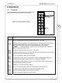
OPERATING MANUAL
FIRELARM 2500
4 ZONE
FIRE ALARM CONTROL PANEL
CPG Signals
2519 4th Ave., P.O. Box 590, Moline, IL 61265
(800) 577-5758 / (309) 762-0731 / FAX (309) 762-8215
www.cpglifesafety.com
CPG #2561255 Rev. A 0209
CPG #2561255
FIRELARM 2500 Operating Manual
Warranty
CPG products are covered by a limited warranty. See CPG’s warranty statement for more information
(document #780-0762).
CPG #2561255
FIRELARM 2500 Operating Manual
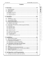
Contents
1.1
General description ...................................................................................................................1-1
1.2
System features .........................................................................................................................1-1
1.3
Specifications ............................................................................................................................1-2
1.3.1 Electrical specifications............................................................................................................1-2
1.3.2 Housing ....................................................................................................................................1-2
1.3.3 Service use: NFPA-72 .............................................................................................................1-3
1.3.4 Listings and approvals .............................................................................................................1-3
2 Operation..............................................................................2-1
2.1
Touchpad....................................................................................................................................2-1
2.2
Visual indicators (LEDs) ...........................................................................................................2-2
2.3
Normal Standby Condition .......................................................................................................2-3
2.4
Silence and reset operation......................................................................................................2-3
2.4.1 Silencing a non-normal condition (buzzer or NAC)..................................................................2-3
2.4.2 Resetting an alarm condition ...................................................................................................2-3
2.4.3 Resetting a trouble condition ...................................................................................................2-3
2.5
Alarm, trouble, and supervisory conditions (by panel LED label) .......................................2-3
2.5.1 Ground fault .............................................................................................................................2-3
2.5.2 Annunciator trouble ..................................................................................................................2-3
2.5.3 NAC trouble / silence ...............................................................................................................2-4
2.5.4 Supervisory trouble ..................................................................................................................2-4
2.5.5 Initiating zone trouble...............................................................................................................2-4
2.5.6 …..............................................................................................................................................2-4
2.5.7 Initiating circuit alarm ...............................................................................................................2-4
2.5.8 Auxiliary power output conditions ............................................................................................2-5
2.5.9 Battery power conditions..........................................................................................................2-5
2.5.10 AC power conditions ............................................................................................................2-5
2.5.11 System trouble......................................................................................................................2-5
2.5.12 Supervisory initiating device circuit ......................................................................................2-5
3 Installation............................................................................3-1
3.1
Safety message to installers ....................................................................................................3-1
3.2
NFPA and UL installation requirements..................................................................................3-1
3.2.1 Requirements for all installations .............................................................................................3-1
3.2.2 Requirements for Local Fire Alarm Systems ...........................................................................3-1
3.2.3 Requirements for Auxiliary Fire Alarm Systems ......................................................................3-1
3.2.4 Requirements for Remote Station Fire Alarm Systems ...........................................................3-1
3.2.5 Requirements for Central Station Fire Alarm Systems ............................................................3-2
3.3
Installing the cabinet (and optional bezel)..............................................................................3-2
3.4
Wiring..........................................................................................................................................3-3
3.5
Quick Reference Operating Instructions form .......................................................................3-3
3.6
Zonal Digital Alarm Communicator Transmitter (optional ZDACT)......................................3-3
3.7
Battery size requirements.........................................................................................................3-3
3.8
Notification Appliance Circuits Connections .........................................................................3-7
4 Configuration and Programming .......................................4-1
4.1
Selecting connected device options (DIP switches)..............................................................4-1
i
Contents
1 Overview...............................................................................1-1
1
2
3
4
5
A
B
C
D
CPG #2561255
FIRELARM 2500 Operating Manual
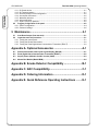
Contents
4.1.1 B1 Strobe device......................................................................................................................4-1
4.1.2 B1 Temporal pattern ................................................................................................................4-1
4.1.3 Reverse polarity circuits configuration .....................................................................................4-2
4.1.4 Annunciator disconnect............................................................................................................4-2
4.1.5 Waterflow detectors .................................................................................................................4-2
4.1.6 Alarm verification......................................................................................................................4-2
4.1.7 Style D (Class A) operation......................................................................................................4-2
4.2
Program configuration of the panel.........................................................................................4-2
4.2.1 ZDACT configuration ...............................................................................................................4-4
4.2.2 Password settings ....................................................................................................................4-6
5 Maintenance .........................................................................5-1
5.1
Auto Reset feature (One-man test) ..........................................................................................5-1
5.2
Inspection and Test procedure ................................................................................................5-1
5.2.1 Testing the control panel..........................................................................................................5-1
5.2.2 Testing the Remote Annunciator .............................................................................................5-2
5.2.3 Testing the Zonal Digital Alarm Communicator Transmitter (ZDACT) ....................................5-2
Appendix A. Optional Accessories ....................................... A-1
A.1
A.2
A.3
A.4
Remote Annunciator with Liquid Crystal Display (RALCD) ................................................. A-1
Zonal Digital Alarm Communicator Transmitter (ZDACT).................................................... A-2
Style Z (Class A) Module for NAC circuits (CAM) ................................................................. A-3
Master Box Module (Model MBM) ........................................................................................... A-4
Appendix B. Smoke Detector Compatibility ......................... B-1
Appendix C. NAC Compatibility............................................. C-1
Appendix D. Ordering Information ........................................ D-1
Appendix E. Quick Reference Operating Instructions ........ E-1
ii
CPG #2561255
FIRELARM 2500 Operating Manual
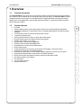
1 Overview
1.1
General description
The FIRELARM 2500 is an economical, conventional Fire Alarm Control Panel (FACP) with an extensive
list of features. When installed with an appropriate battery backup supply, the FireLarm 2500 provides a
complete fire alarm control system for most applications. Available accessories include liquid crystal
display (LCD), zonal digital alarm communicator transmitter (ZDACT), remote annunciators, and NAC
Style Z (Class A) modules.
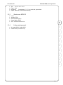
1.2
System features
•
•
•
•
•
•
•
•
•
•
•
•
•
•
•
•
•
•
•
•
•
UL Listed
4 alarm initiating device circuits (IDCs) Style D (Class A) or Style B (Class B) configurable
2 Notification Appliance Circuits (NACs), Style Y (Class B) (Optional Style Z (Class A) module
available)
2.5 Amps total current for NAC and auxiliary power circuits
1 supervisory initiating zone
Reverse polarity output for alarm, or alarm and trouble signals
Reverse polarity output for trouble and supervisory signals
Auxiliary power output, up to .5 Amp
Auxiliary alarm contacts rated 2A@30VDC
Auxiliary trouble contacts rated 2A@30VDC
Compatible with 2- and 4-wire smoke detectors
Power limited circuits
Custom descriptions for each zone (with optional LCD display or LCD annunciator)
On-board 2x16 character LCD display (optional)
Remote annunciator with 2x16 LCD character display (optional), maximum of 2 per panel
On-board Zonal Digital Alarm Communicator Transmitter (optional)
Built in piezo-buzzer with distinctive trouble, supervisory and alarm signals
One-man test feature (Auto Reset)
Fire drill feature
12 hour trouble reminder
Password protection
1
2
3
4
5
A
B
C
D
E
1-1
CPG #2561255
1.3
Specifications
Contents
1.3.1
1
FIRELARM 2500 Operating Manual
Electrical specifications
Primary (AC) power:
Accessory (battery) voltage
Control Unit Requirements:
Standby current
Alarm current
Output Ratings:
System alarm contacts
System trouble contacts
4-wire smoke detector power
Auxiliary power
Max ripple voltage
Optional Accessories:
Remote annunciator RALCD
Max number per panel
Style Z (Class A) Module (CAM)
ZDACT
Notification Appliance Circuit (Bells): **
Current, nominal
Max short circuit current
Normal supervisory current
End of line resistance
Initiating Device Circuits (Zones):
Smoke capacity (24VDC)†
Standby voltage
Max ripple voltage
Max short circuit current
Normal standby current
Alarm current threshold
Max impedance for alarm
End of line resistance
Max. line resistance
Supervisory Initiating Circuit:††
Max voltage
Max short circuit current
Max circuit resistance
Normal supervisory current
Trouble current
End of line resistance
Reverse Polarity Outputs:††† Max
voltage
Max line current
120VAC, 60 Hz, 1.5A max
24VDC; (charging current, 1.0A)
110mA, 24VDC (not including auxiliary devices and
modules) 200mA, 24VDC (not including auxiliary devices
and modules)
SPDT, 2A, 30VDC, 0.6 power factor
SPDT, 2A, 30VDC, 0.6 power factor
24VDC, .5A power limited, regulated, resetable***
24VDC, .5A power limited, regulated, resistive load, nonresetable***
500mV (4-wire smoke and aux. power circuits)
Power limited,100mA, 24VDC per unit, (see Appendix A)
2
0mA standby, 25mA alarm (see Appendix A)
90mA max in alarm (See Appendix A)
24VDC, 2.0A (max) ***, power limited
2.5A, power limited
2.7mA
5.1K ohms
25 detectors, 0.1mA type; 20 detectors, 0.12mA type
27.5 VDC (max) to 16 VDC (min)
500mV
60mA, power limited
4.5mA
approx. 20mA
1.5K ohms
5.1K ohms
100 ohms
27.5 VDC
10mA, power limited
100 ohms
3.5mA
2mA (low trouble) 5mA (supervisory)
5.1K ohms
24 VDC
15mA
* All terminals are capable of up to #12 AWG wire.
** Use any UL listed polarized notification appliances rated 24VDC.
***Total system current for auxiliary device powered by the panel not to exceed 2.5 amps. This includes NAC power, auxiliary
power, reverse polarity outputs, four wire detector power, and remote annunciator. The latter three are 0.5A max combined.
† Max load: 2.5mA. Use only detectors that are listed in compatibility list.
†† Use supervisory devices with normally open contacts.
††† Power limited
1.3.2
•
1-2
Housing
Type
18-gauge sheet steel with hinged, removable, locked door.
CPG #2561255
•
•
•
•
1.3.3
•
•
•
•
•
1.3.4
•
•
FIRELARM 2500 Operating Manual
Size
18-½" x 14-¼" x 3-¾"
Finish Red.
Knockouts
Combination ½" / ¾", 2 on each side, top and back.
Option Bezel trim for semi-flush mounting.
Service use: NFPA-72
Local
Auxiliary (PPU)
Remote Station (PPU)
Central Station (PPU)
PPU - Protected Premise Unit.
1
Listings and approvals
2
UL Listed (S6521, Guide UOJZ)
CSFM Listed (7165-0476:154)
3
4
5
A
B
C
D
E
1-3
Contents
CPG #2561255
1
1-4
FIRELARM 2500 Operating Manual
CPG #2561255
FIRELARM 2500 Operating Manual
2 Operation
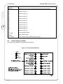
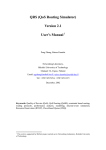
2.1
Touchpad
The touchpad provides user control over the operation of the
panel. It is readily accessible when the cover is open.
Figure 2-1. FireLarm 2500 Touchpad.
2
3
4
Primary
Function
Primary Function Description
Resets all alarm circuits if condition has been corrected, removes power from initiating
device circuit and auxiliary power from smoke detectors for 7 seconds.
Disables notification appliance circuit and trouble buzzer. Silencing an alarm condition will
cause bell trouble LED to flash. If both buzzer and NAC are on, the first press of
ACK/SILENCE will silence the buzzer; the second press will silence the NAC.
Silencing an alarm or trouble on one zone will not prevent a subsequent
alarm or trouble from another zone.
Toggles one-man test mode. See section 5.1 Auto Reset.
Turns on all indicators, alarm and trouble outputs.
Scrolls through trouble conditions, if present. For configuration mode, scrolls through the
character set when entering zone labels.
Pressing for 2 seconds will initiate a fire drill.
5
Toggles reverse polarity circuits from generating alarm or trouble condition, causes system
trouble and trouble at the supervising station
A
B
C
D
Toggles ability for each zone to generate alarm condition. Disabled state causes zone
trouble and system trouble. Does not function if configured for waterflow.
E
Used in configuration mode, for saving a configuration and various functions.
To begin program configuration and change the configuration mode.
Used in configuration mode; return to the previous screen.
Used in configuration mode, and various functions.
2-1
Contents
CPG #2561255
1
2
FIRELARM 2500 Operating Manual
Secondary
Function
Secondary Function Description
(DELETE)
(YES)
(NO)
(comma)
Deletes the value at the cursor location when entering numeric values.
2.2
Numeric entry of 1.
Numeric entry of 2.
Numeric entry of 3.
Numeric entry of 4.
Numeric entry of 5.
Numeric entry of 6.
Numeric entry of 7.
Numeric entry of 8.
Numeric entry of 9.
Numeric entry of 0.
Confirm change of data.
Abort change of data.
Enter 2-second delay for ZDACT phone number.
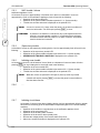
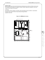
Visual indicators (LEDs)
The LED’s give immediate visual indication of panel status.
Figure 2-2. FireLarm 2500 LED label
2-2
CPG #2561255
2.3
FIRELARM 2500 Operating Manual
Normal Standby Condition
The AC LED indicator is on with all other LED’s off.
The fire alarm system is constantly monitoring all circuits for alarm signals, faults and
remote communication.
The panel optional LCD will display SYSTEM NORMAL when the system is operating as
normal.
2.4
2.4.1
Silence and reset operation.
Silencing a non-normal condition (buzzer or NAC)
Press
Press
.
again to silence NAC if buzzer was silenced first.
Where audible and/or visual indicators are being used as an evacuation
signal, do not silence an alarm condition without investigating and
determining that an emergency condition does not exist.
2
Alarms initiated from zones that are in the waterflow mode cannot be
silenced. The panel must be reset to silence audible alarm devices.
Silencing an alarm condition will cause the bell trouble LED to flash.
2.4.2
3
4
Resetting an alarm condition
Determine the cause of the alarm condition and if necessary remove the cause.
Press
2.4.3
.
5
Resetting a trouble condition
Determine the cause of the trouble condition and remove the cause.
This condition is self-restoring. When all trouble conditions are removed all indications
will return to normal.
A
When an alarm initiating device zone is operated in a Style D (Class A) mode
B
any trouble condition will require pressing to restore the panel to
normal after the fault has been corrected. A trouble condition of an indicating
circuit that is the result of a current in excess of 2.5 amps requires pressing
C
. See Caution in section 2.5.3 NAC trouble / silence.
2.5
2.5.1
Alarm, trouble, and supervisory conditions (by panel LED label)
D
Ground fault
A ground fault will result in the following:
Operation of the ground fault LED.
Operation of all system trouble indications (see section 2.5.11 System trouble).
GROUND FAULT is displayed on the optional LCD.
2.5.2
E
Annunciator trouble
The annunciator trouble is used to indicate a trouble condition on the optional remote annunciator if used.
Annunciator trouble is caused by a communication fault from lack of response or incorrect transmission
and will result in the following.
Operation of the annunciator trouble LED
REM. ANNUNCIATOR TROUBLE is displayed on optional LCD
2-3
CPG #2561255
Contents
2.5.3
FIRELARM 2500 Operating Manual
NAC trouble / silence
Notification appliance circuit:
An increase of current to approximately 3.5mA when not in alarm or a decrease in current to
approximately 1.5mA on the notification appliance circuit will result in the following:
Operation of the bell trouble LED.
Operation of all system trouble indications (section 2.5.11 System trouble).
Trouble zone number and name is displayed on the optional LCD.
A current in excess of 2.5 amps, when the panel is in the alarm condition will
result in a bell trouble. This will require pressing to clear.
1
A problem in an audible or visual device may not be apparent when the
panel is in a normal standby condition. If a notification device indicates
a trouble condition when the panel is in an alarm condition, the problem
must be located and corrected.
2
2.5.4
Supervisory trouble
A decrease of current on the supervisory initiating device circuit to approximately 2mA will result in the
following:
Operation of the supervisory trouble LED.
Operation of all system trouble indications (see section 2.5.11 System trouble).
SUPERVISORY TROUBLE CONDITION is displayed on the optional LCD.
2.5.5
Initiating zone trouble
An increase in current to a level between 7mA to 20mA or a decrease of current to below 3.0mA or
pressing for any initiating device circuit will result in the following:
Operation of the zone trouble LED.
Operation of all system trouble indications (see section 2.5.11 System trouble).
Trouble zone number and name is displayed on the optional LCD.
When the circuits are operated in the Style D (Class A) mode any trouble
condition will require pressing to restore the panel to normal after the
fault has been removed.
2.5.6
…
2.5.7
Initiating circuit alarm
An increase of current on any alarm initiating device circuit to approximately 20mA or greater
will result in the following (if all the associated touchpad settings are in the normal standby
condition).
Operation of the audible or visual devices on the notification appliance circuit.
Operation of the zone alarm LED.
Operation of the auxiliary alarm contacts.
Operation of the buzzer for alarm (steady tone).
Reverse the voltage polarity of the remote alarm (RA) circuit.
Alarm zone number and name is displayed on the optional LCD.
2-4
CPG #2561255
FIRELARM 2500 Operating Manual
2.5.8
With the exception of the loss of the AC-ON LED and transfer of the
auxiliary trouble relay contacts, none of the trouble indicators will
operate on loss of AC unless an adequately charged battery is
connected to the proper terminals.
Auxiliary power output conditions
Loss of output of the auxiliary power will result in the following:
Operation of the auxiliary power LED.
Operation of all system trouble indications (see section 2.5.11 System trouble).
AUXILIARY POWER TROUBLE will be displayed on the optional LCD.
2.5.9
Battery power conditions
The battery circuit is power limited and reverse polarity protection is provided. Loss of or reduction of
battery voltage to 23 volts or increase to 29 volts or more will result in the following:
Operation of the battery trouble LED.
Operation of all system trouble indicators (see section 2.5.11 System trouble)
If batteries are disconnected, the system trouble and battery LEDs will light and the
buzzer will sound after 30 seconds.
BATTERY TROUBLE will be displayed on the optional LCD.
2
3
There is a time delay of approximately 1 minute for battery trouble to restore.
2.5.10
AC power conditions
4
Loss or Reduction of AC:
A reduction in the AC input voltage would result in the following:
Green AC LED will be extinguished.
Operation of all system trouble indications (see section 2.5.11 System trouble).
AC TROUBLE will be displayed on the optional LCD.
2.5.11
5
System trouble
A
All the previously listed trouble conditions will, in addition to the specific indication previously shown,
result in the following common trouble indications:
Operation of the system trouble LED.
Operation of the buzzer for trouble (slow beep - 1 pulse every two seconds).
Transfer of the auxiliary trouble contacts.
Opens the circuits of the remote alarm and supervisory outputs.
A description of the trouble will be displayed on the LCD.
B
C
This panel incorporates a trouble reminder feature. If a trouble is silenced
and the cause of the trouble is not rectified, the trouble buzzer will resound
12 hours after the panel is silenced.
2.5.12
D
Pressing , or any touchpad, also results in the
operation of the system trouble indications listed above.
E
Supervisory initiating device circuit
Supervisory Condition:
An increase of current to approximately 5mA or greater on the supervisory initiating device circuit will
result in the following:
Operation of the supervisory LED.
Reverse the voltage polarity of the remote supervisory output (RS).
Operation of the buzzer for supervisory (fast beep - 1 pulse per second).
Operation of all system trouble indications except buzzer pattern (see section 2.5.11
System trouble)
SUPERVISORY CONDITION is displayed on the optional LCD.
2-5
Contents
CPG #2561255
1
2
2-6
FIRELARM 2500 Operating Manual
CPG #2561255
FIRELARM 2500 Operating Manual
3 Installation
3.1
Safety message to installers
People's lives depend on your safe installation of our products. It is
important to read, understand, and follow all instructions shipped with
this product.
The Facilities Engineer and the Safety Engineer should make selection of mounting location for this
product, its controls, and routing of wire. Listed below are some other important safety instructions and
precautions you should follow.
•
•
•
•
•
•
3.2
Read and understand the entire manual before attempting to install this panel.
System wiring should be installed and maintained in accordance with section 70 (Fire
Protection Signaling Systems) and all other applicable sections of the National Electrical
Code, all Local Code, all applicable NFPA Codes and Standards and the Authority
Having Jurisdiction. Review the circuit parameters listed under “Electrical specifications”
before installing the panel.
Do not connect devices or system wiring when circuits are energized.
After installation, be sure all threaded joints are securely tightened.
After installation and completion of initial system test, a program for periodic testing of
this system must be established. Refer to NFPA 72, local fire codes, and the authority
having jurisdiction for this information.
After installation and completion of final test, provide a copy of this instruction manual to
all personnel responsible for operation, periodic testing, and maintenance of this system.
Requirements for all installations
This section describes general installation requirements. Refer to the appropriate section(s) for additional
requirements for more specific installation.
•
•
•
•
•
3.2.2
4
5
NFPA and UL installation requirements
3.2.1
3
Read and follow all items in the safety message to installers above.
Use appropriate secondary power supply (battery, see section 3.7).
Use compatible smoke detectors listed in Appendix B.
Use UL listed notification appliances with compatible ratings.
A full system check must be performed any time the panel is programmed.
A
B
C
Requirements for Local Fire Alarm Systems
•
3.2.3
D
At least one notification appliance must be used.
Requirements for Auxiliary Fire Alarm Systems
•
3.2.4
Use the MBM and a municipal city tie box as the interface between the local control panel
and the public fire service communications center (see Appendix A for wiring and more
information).
Requirements for Remote Station Fire Alarm Systems
•
•
•
A UL497A Listed Secondary Protector for Communications Circuits must be used on the
remote station terminals.
Either the reverse polarity outputs or the DACT may be used for Remote Station. See
section 4.1.3 for configuration of the reverse polarity outputs. Or install optional ZDACT
and OPLCD (see sections 3-3, 4-4, and A-2).
Set the AC trouble report delay from 15 to 30 hours.
3-1
E
CPG #2561255
3.2.5
•
Contents
•
3.3
FIRELARM 2500 Operating Manual
Requirements for Central Station Fire Alarm Systems
Connect both phone lines to the optional ZDACT and OPLCD and program the telephone
numbers for the reporting station.
Set the AC trouble report delay from 6 to 12 hours.
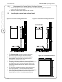
Installing the cabinet (and optional bezel)
Figure 3-1. Surface mounting dimensions
Figure 3-2. Semi-flush mounting dimensions
1
2
3
1. The FIRELARM 2500 unit may be surface mounted or
semi-flush mounted using the optional trim bezel.
2. The unit should be mounted in a convenient location,
approximately 4 feet from the floor where it will be
accessible for testing and servicing.
3. The main circuit board module can be removed before
attempting to mount the cabinet. Disconnect the two wires of
the transformer from P2 on the main board. Remove the
eight Philips head screws and lock washers. Remove the
circuit board.
4. For semi-flush installations mount the housing so that the
front edge protrudes 1" from the finished wall surface.
5. After all conduits and wiring are in place and the wall surface
is completely finished, slide the trim bezel in place and
fasten with four #6-32 x ¼" machine screws and nuts.
Figure 3-3. Trim bezel dimensions
3-2
290-0005
CPG #2561255
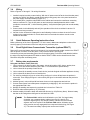
3.4
FIRELARM 2500 Operating Manual
Wiring
Refer to Figures 3-5 through 3-7 for wiring information.
1. Install all required conduits, external wiring. With the AC power turned off at the circuit breaker panel,
connect the 120VAC hot (black), neutral (white) and ground (green) wire to the panel as shown on
the power supply connection drawing (Figure 3-7).
2. If not already done, install the main board into the cabinet and connect the transformer secondary
leads to connector P2. Turn the AC power on and connect the standby batteries with the cable
provided to connector BAT 1, while observing polarity. Verify that the panel goes into normal standby
condition.
3. Connect each circuit individually and verify the operation of the circuit as outlined in section 5.2
Inspection and test procedure.
4. Inactive circuits: All inactive initiating device and indicating circuits must have the end of line test
resistor on the panel terminals. On circuits that have four terminals the resistor must be on the
outside two terminals.
3.5
Quick Reference Operating Instructions form
Make a photocopy of the form in Appendix E. Fill in the name, address and telephone number of the
servicing agency on the bottom of the form and post in a prominent place.
3.6
3
Zonal Digital Alarm Communicator Transmitter (optional ZDACT)
Remove AC power and battery power from the panel. Line up the electrical contact socket on the ZDACT
with the pins on connector J8 on the panel. Firmly insert the ZDACT into the pins.
Connect the primary and secondary phone lines to the phone jacks. Peel off the small adhesive label at
the edge of the large black plastic LED label so that the ZDACT LED's can be viewed from the front.
Reconnect AC power and battery power.
3.7
4
5
Battery size requirements
Using the Calculation Table (Table 3-3):
1. List in column #1 all devices used in the system; include all modules, NAC, horns, strobes, door
holders, and 4-wire smoke detectors (see Table 3-1 or manufacturer’s specifications).
2. List in column #2 the quantity of each device.
3. List in column #3 the standby current of each device (exclude all signal notification appliance circuits).
4. List in column #5 the alarm current of each device.
5. For each line multiply the figure in column #2 by the figure in column #3 and enter the product in
column #4. Then multiply the figure in column #2 by the figure in column #5 and enter the product in
column #6.
6. Add the figures in column #3 and #6 and enter the sums in the appropriate total mA box.
7. Convert these figures from milliamperes to amperes by multiplying by .001 and enter the product in
the appropriate total A box.
8. Multiply the standby total amperes by required time in hours from Table 3-2.
9. Divide the alarm total amperes by 12 (5 minutes).
10. Add the standby AH and the alarm AH and divide this sum by .85 (efficiency factor). Select a battery
that has an AH rating above this figure but not less than 6.5AH.
The FireLarm 2500 cabinet can hold batteries up to 7AH. If a larger battery
is needed, use a separate battery cabinet (must be UL Listed for Fire
Protective Signaling Use). Any auxiliary battery cabinets must be mounted
adjacent and close-coupled to the FireLarm 2500 cabinet. All battery power
wiring must be securely segregated from nonpower-limited wiring (see Figure
3-7). The maximum battery capacity that can be used is 44AH.
3-3
A
B
C
D
E
CPG #2561255
FIRELARM 2500 Operating Manual
Contents
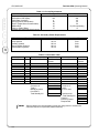
Table 3-1: Current Requirements.
1
2
3
Module/Device
2500 with LCD display
2500 without LCD display
CAM (Class A module)
RALCD (Remote Annunciator)
ZDACT (Digital Alarm Communicator)
MBM module
PAM-1 or PAM-2 Relay
*Includes one zone short circuit current.
Standby mA
170
105
0
95
30
30
15
Alarm mA
310*
250
25
115
50
15 (250 momentary)
15
Table 3-2: Secondary Power Requirements.
NFPA-72 National Fire Alarm Code
Local Systems
Auxiliary Systems
Remote Station Systems
Central Station Systems
Standby Time
Alarm Time
24 hrs.
60 hrs.
60 hrs.
24 hrs.
5 min.
5 min.
5 min.
5 min.
Table 3-3: Calculation Table.
1
Module/Device
2
Qty.
3
Standby mA Per Unit
Total mA
Convert to A
Total A
Multiply by hours
from table 2
Total Standby AH
4
Total Standby
Current
X 0.001
X
5
Alarm mA Per Unit
Total mA
Convert to A
Total A
AH for 5 mins.
6
Total Alarm
Current
X 0.001
Total Alarm AH
+ Total Standby AH
Total AH
Efficiency Factor
Required AH
Select a battery such that the battery’s amp hour rating meets or exceeds the
calculated amp hour requirement (44AH maximum).
3-4
÷ 12
÷ 0.85
CPG #2561255
FIRELARM 2500 Operating Manual
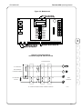
Figure 3-4. Motherboard.
#
%
!
"
! " ( !
"
$
#
!
"
! " & '
3
& ' 290-0006
4
5
Figure 3-5. Four-wire detector
connections (Style B, Class B cuircuit
A
SEE APPENDIX D
FOR MODEL NUMBERS
EOL RESISTOR
5.1K OHM
N.O.
N.O.
42
B
43
C
IN
OUT
IN
OUT
IN
UL LISTED RELAY
OUT
4-WIRE DETECTORS
N.O.
ZONE
TERMINALS
D
E
ALL CONTACTS SHOWN IN NORMAL STANDBY CONDITION
290-0007
3-5
3-6
(+)
19
(-)
(+)
(-)
5.1K
21
22
(-)
(+)
24
(+)
(-)
5.1K
25
26
(-)
SEE ZONES 1 AND 2 AND BELL 1
FOR TYPICAL CONNECTIONS
23
(SUPERVISED)
(SUPERVISED)
20
ZONE 4
ZONE 3
6
BELL 2
27
(+)
(+)
7
(-)
8
(-)
(-)
5.1K
28
9
(+)
(+)
(NOT SUPERVISED)
N.C.
32
5.1K
14
N.O.
33
TYPICAL
STYLE Y (CLASS B)
WIRING
5.1K
37
(+)(-)
36
24VDC 2A MAX
290-0008
N.C.
35
(SUPERVISED)
GND
17
+24V
18
39
(-)
40
(+)
41
* THE REMOTE STATION
MUST PROVIDE
SUPERVISION
AN ECLIPSE MODEL FA24VB
MUST BE USED ON REMOTE
STATION CIRCUITS.
INTENDED FOR
CONNECTION TO A
POLARITY REVERSAL
CIRCUIT OF A REMOTE
STATION RECEIVEING
UNIT THAT HAS
COMPATIBLE RATINGS.
(-)
(SUPERVISED*)
RS
SUPERVISORY
24VDC .015A MAX
EACH CIRCUIT
(+)
38
(SUPERVISED*)
RA
ALARM
42
43
(-)
SEE NOTE 6
24VDC
(+)
(SUPERVISED)
4-WIRE
DET. PWR
EARTH
(OPTIONAL)
E
REMOTE STATION
REMOTE ANNUNCIATOR
D*
D
BELL 1
TB4
16
15
USE POLARIZED
DEVICES ONLY
AUX. CONTACTS RATED
2A @ 30VDC
0.6 POWER FACTOR
COM
34
AUXILIARY
TROUBLE
USE N.O. SUPV
SWITCHES
13
USE POWER LIMITED
CIRCUITS ONLY.
COM
31
(-)
E
GND
12
All circuits powered by this panel are power limited.
Transformer, battery, auxiliary alarm and auxiliary trouble
connections are not power limited.
N.O.
30
AUXILIARY
ALARM
29
(-)
5.1K
11
TYPICAL
STYLE B (CLASS B)
WIRING
10
(2 MAX, 100mA PER UNIT)
(SUPERVISED)
REMOTE ANNUNCIATOR
POWER LIMITED
TB1A
TYPICAL
STYLE D (CLASS A)
WIRING
(+)
(SUPERVISED)
TB1
5
1) Use only smoke detectors that are listed in compatibility listing in owner's manual.
2) Any zone (except supervisory zone) can be operated in a Style D (Class A) mode. The
end-of-line resistor is in the panel when Class A mode is used.
3) Leave end-of-line test resistors on unused circuits.
4) Combined load of all external devices, including indicating appliances, is not to exceed
2.5A.
5) Polarities shown are for normal standby condition. Bell and remote station circuits
reverse polarity when activated.
6) Combined load of remote annunciator, 4-wire detectors, and auxiliary power (terminals
17, 18, 42, 43, and 44) is not to exceed .5A.
7) All EOL resistors are 5.1K ohms (#024-4556)
NOTES:
TB2
(+)
4
120VAC - 60 HZ
(2) 12V, 6.5 AH min. batteries are required.
Maximum battery charge current: 1A
The battery set must be replaced every 4 years or earlier if capacity is
excessively reduced. The batteries should be checked at least twice a
year, or more often if required by local codes.
POWER RATING
SECONDARY
WINDING OF
TRANSFORMER
BATT
3
(SUPERVISED)
SUPERVISORY
2
P2
4
ZONE 2
(SUPERVISED)
ZONE 1
(SUPERVISED)
3
(SUPERVISED)
BATTERY
CONNECTOR
1
3
TRANSFORMER
CONNECTOR
Contents
44
(+)
AUX.
PWR
CPG #2561255
FIRELARM 2500 Operating Manual
Figure 3-6. Device Wiring
CPG #2561255
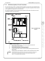
3.8
FIRELARM 2500 Operating Manual
Notification Appliance Circuits Connections
The control panel has two Style Y (Class B) notification appliance circuits which can be upgraded to Style
Z (class A) by the addition of a model CAM (Class A Module). One module is required for each circuit that
is to be upgraded. See Appendix A for more information.
The notification appliance circuits are power limited, regulated 24 VDC rated at 2.0 amperes max each.
(Total system current not to exceed 2.5 A.)
3
4
Figure 3-7. Wire Routing
Diagram
5
A
B
C
290-0009
D
Notes for Figure 3-7:
1.
Power inputs (not power limited). Wire wrap to standoff for strain relief.
2.
Battery leads (not power limited).
3.
Use left hand knockouts for non-power limited wiring.
4.
Use right hand knockouts for power limited wiring.
5.
Connect earth ground to corner of main board using a #6 ring terminal or wire and
ring provided.
6.
All wiring must be wire-wrapped to a standoff or other mechanically secure location.
All field-installed wiring connected to this panel must maintain a spacing of ¼
inch between all power-limited conductors and all electrical light, power,
Class 1, or non-power limited conductors.
3-7
E
Contents
CPG #2561255
1
2
3
3-8
FIRELARM 2500 Operating Manual
CPG #2561255
FIRELARM 2500 Operating Manual
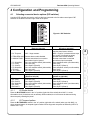
4 Configuration and Programming
4.1
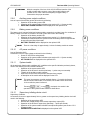
Selecting connected device options (DIP switches)
A series of DIP switches are used to configure devices connected to the fire alarm control panel. DIP
switches are located in the lower right corner of the panel.
Figure 4-1. DIP Switches
DIP Switch 9
1. B1 Strobe
Description of Disabled States
(Switch to left side)
NAC 1 devices are silenceable.
2. B1 Temporal
NAC 1 rings constant
3. TRBL-REM ALM
4. ANNUNC DISC
Remote alarm trouble disabled.
Remote annunciator is not used or
annunciator input is ignored.
Zone not waterflow switch (silenceable)
Zone not verify
Zone Style B (Class B)
Zone not waterflow switch (silenceable)
Zone not verify
Zone Style B (Class B)
Description of Enabled States
(Switch to right side)
NAC 1 devices are non-silenceable –
requires panel reset to silence.
NAC 1 rings for 3 pulses and then stops
for 1 pulse (1/2 second per pulse)
Remote alarm trouble enabled.
Remote annunciator is used and
annunciator input is accepted.
Zone waterflow switch (not silenceable)
Zone verify
Zone Style D (Class A)
Zone waterflow switch (not silenceable)
Zone Verify
Zone Style D (Class A)
Description of Disabled States
(Switch to left side)
Zone not waterflow switch (silenceable)
Zone not verify
Zone Style B (Class B)
Zone not waterflow switch (silenceable)
Zone not verify
Zone Style B (Class B)
Description of Enabled States
(Switch to right side)
Zone waterflow switch (not silenceable)
Zone verify
Zone Style D (Class A)
Zone waterflow switch (not silenceable)
Zone verify
Zone Style D (Class A)
5. Z1- Waterflow
6. Z1- Verify
7. Z1- Class A
8. Z2- Waterflow
9. Z2-Verify
10. Z2- Class A
DIP Switch 10
1. Z3- Waterflow
2. Z3- Verify
3. Z3- Class A
4. Z4- Waterflow
5. Z4- Verify
6. Z4-Class A
4.1.1
5
A
B
C
D
E
B1 Strobe device
Place the B1 STROBE switch in the “on” position (right side of the switch) when NAC 1 is a nonsilenceable circuit (for devices such as strobes). When enabled, the circuit cannot be silenced during
alarm except by resetting the panel.
4.1.2
4
B1 Temporal pattern
Place the B1 TEMPORAL switch in the “on” position (right side of the switch) when you wish NAC 1 to
ring a temporal pattern. A temporal signal consists of three rings and one pause as defined by NFPA 72,
Section A-3-7.2 (2).
4-1
CPG #2561255
4.1.3
FIRELARM 2500 Operating Manual
Reverse polarity circuits configuration
Contents
This panel is equipped with two polarity reversal-type outputs. This permits alarm and trouble signals to
be transmitted to one location and supervisory and trouble signals to be transmitted to a second location.
If trouble signals are to be transmitted to the alarm location or if only the remote alarm circuit is used,
place the TRBL-REM ALM switch in the “off” position (left side of the switch). When configured in this
manner, supervisory alarms are sent as trouble signals on the remote alarm circuit.
1
4.1.4
2
3
4
When the remote alarm output is programmed to transmit a trouble
condition, the control panel is not suitable for remote station protected
premises service where separate transmission circuits are required for
fire, supervisory, and trouble signals. This should not be done unless
approved by the Authority Having Jurisdiction
Annunciator disconnect
Place the ANNUNC DISC switch in the “on” position (right side of the switch) when you wish to ignore
commands sent from the remote annunciator or when an annunciator is not connected.
4.1.5
Waterflow detectors
Place the WATERFLOW switch in the “on” position (right side of the switch) for all zones that are to be
used with waterflow detectors. The SILENCE and ZONE DISABLE keypads can not be used for zones
configured for waterflow. Instead, the panel must be reset to silence the alarm notification device.
4.1.6
Alarm verification
Place the VERIFY switch in the “on” position (right side of the switch) to place a zone in the alarm
verification mode.
This mode should only be used with smoke detectors that do not include an alarm verification feature.
When a smoke detector operates on a zone that has been selected for alarm verification, the panel will
not immediately go into an alarm condition.
Power will be removed for a period of 6 to 8 seconds, which will reset the detector. Power is then
reapplied, but alarms are inhibited for the next 3 to 6 seconds.
If any detector operates within the following confirmation period of approximately 120 seconds, an alarm
condition will result.
4.1.7
Style D (Class A) operation
Any initiating device zone (except the supervisory zone) can be operated in a Style D (Class A) mode.
To place a zone in the Style D (Class A) mode, place the CLASS A switch in the “on” position (right side
of the switch). Zones that are selected to be Style D (Class A) require a four wire, double loop,
configuration. This permits detection of an alarm condition from any detector on the zone when a single
open fault is present.
4.2
Program configuration of the panel
The optional LCD is used to display system status during operation, show a description of each zone,
and allows configuration of the optional ZDACT. The prompts and possible key presses for configuring
the control panel are shown below to help with configuration. Words in BOLD ALL CAPS print appear in
the LCD.
An LCD display is required for programming the panel. If you do not have an
LCD output, see Appendix C for ordering optional LCD (Model OPLCD) or
remote annunciator (Model RALCD).
4-2
CPG #2561255
FIRELARM 2500 Operating Manual
To enter the configuration mode when no alarms are present, press and enter the four digit
password. If no password has been entered , the default password is required (2402). If no touchpad is
pressed for 30 seconds while in configuration mode, the panel returns to normal standby condition. The
configuration mode cannot be entered if alarms are present. Zone labeling
SETUP ZONES?
To program zone descriptions
To exit configuration
To skip zone setup and go to password setup
To skip zone setup and go to ZDACT setup, if used
ENTER ZONE 1 DESCRIPTION?
or To program the label for zone 1
To exit to SET UP ZONES? Screen
To cycle forward or backward through zone configuration
screens
DESCRIPTION
or To select a character. Press and hold to scroll
quickly through the character set. See below for
order of characters
4
To set the selected letter and advance the cursor
To save the zone description or cancel changes
5
SAVE? (Y/N/BACK)
To save changes and advance to next zone
To keep previous setting and advance to next zone
To modify the zone description
ENTER ZONE 2 DESCRIPTION?
Similar to ENTER ZONE 1 DESCRIPTION above.
ENTER ZONE 3 DESCRIPTION?
Similar to ENTER ZONE 1 DESCRIPTION above.
ENTER ZONE 4 DESCRIPTION?
Similar to ENTER ZONE 1 DESCRIPTION above.
A
B
C
D
E
Order of characters
← key
key →
!"#$%&'()*+,-./0123456789:;<=>?~
ABCDEFGHIJKLMNOPQRSTUVWXYZ[\]^_'
a b c d e f g h i j k l m n o p q r s t u v w x y z { l } ← → (space)
4-3
CPG #2561255
4.2.1
FIRELARM 2500 Operating Manual
ZDACT configuration
Contents
The following programming options occur only when a ZDACT is mounted on
the FireLarm 2500. These options are skipped if no ZDACT is used.
SETUP ZDACT?
1
To configure ZDACT options
To exit configuration mode
To skip ZDACT configuration and go to zone configuration
To skip ZDACT configuration and go to AC trouble reporting delay
configuration
ENTER PHONE NUMBER 1?
or 2
3
To enter phone number 1.
To exit to SETUP ZDACT? screen
To cycle forward or backward through ZDACT configuration
options.
PHONE NUMBER 1:
through To enter phone number digits.
To enter a comma for a 2 second pause in dialing sequence.
To advance the cursor.
To delete the character at the cursor.
To move the cursor back.
To save the zone description or cancel changes.
4
SAVE? (Y/N/BACK)
To save changes and advance to next phone number.
To keep previous setting and advance to next phone
number.
To return to the phone number.
ENTER PHONE NUMBER 2?
Similar to PHONE NUMBER 1
ENTER ACCOUNT NUMBER?
Similar to PHONE NUMBER 1. Up to four digits.
Order of characters
← key
key →
!"#$%&'()*+,-./0123456789:;<=>?~
ABCDEFGHIJKLMNOPQRSTUVWXYZ[\]^_'
a b c d e f g h i j k l m n o p q r s t u v w x y z { l } ← → (space)
4-4
CPG #2561255
FIRELARM 2500 Operating Manual
AC DELAY (HR)?
When an AC trouble condition occurs, the panel will delay the number of hours
programmed under this option. The delay can be set from 6 to 30 hours.
To enter AC trouble reporting delay.
To exit configuration mode.
To skip AC trouble reporting configuration and go to ZDACT
configuration, if used.
To skip AC trouble reporting configuration and go to
password configuration.
AC DELAY (HR):
or To change the value.
To save the value or cancel changes.
SAVE? (Y/N/BACK)
To save changes and advance to password configuration.
To keep previous setting and advance to password
configuration.
To reenter the delay value.
OFFSET TIMER (HR)?
This will set a time delay starting from the entry of the offset timer value for a
phone line check. The check will be performed every 24 hours thereafter. The
24-hour time delay starts from zero on a power cycle of the panel. Keypresses
are similar to AC DELAY (HR)?
4
5
A
B
C
D
E
Order of characters
← key
key →
!"#$%&'()*+,-./0123456789:;<=>?~
ABCDEFGHIJKLMNOPQRSTUVWXYZ[\]^_'
a b c d e f g h i j k l m n o p q r s t u v w x y z { l } ← → (space)
4-5
CPG #2561255
4.2.2
FIRELARM 2500 Operating Manual
Password settings
Contents
Panels from the factory are set to the default password (2402). Change the
password, write it down and store in a safe place for optimum protection.
CHANGE PASSWORD?
1
To change the password
To exit configuration mode
To skip password configuration and go to ZDACT configuration
To skip password configuration and go to zone configuration.
PASSWORD:
NUMBER KEYS
To enter a password up to four digits
2
3
To advance the cursor
To move the cursor back
To save the password or cancel changes
SAVE? (Y/N/BACK)
4
To save changes
To keep previous setting
To modify the password
Order of characters
← key
key →
!"#$%&'()*+,-./0123456789:;<=>?~
ABCDEFGHIJKLMNOPQRSTUVWXYZ[\]^_'
a b c d e f g h i j k l m n o p q r s t u v w x y z { l } ← → (space)
4-6
CPG #2561255
FIRELARM 2500 Operating Manual
5 Maintenance
Most modern control units do not require periodic adjustment or field repair other than replacement of a
module or printed circuit board assembly. Defective printed circuit board assemblies or modules can best
be serviced at the manufacturer’s plant or at their authorized service facility. Where the control unit uses
printed circuit boards, care should be taken to clean off excessive dust. The boards should be maintained
clean and dry to ensure proper operation.
5.1
Auto Reset feature (One-man test)
This function only works when the panel is in the standby mode. Pressing sets the panel into oneman test mode. When a zone goes into alarm, the audible circuits are pulsed ½ second for identification
of the zone; i.e. zone 1 has one pulse, zone 2 has two pulses, etc. After the zone number is pulsed, the
panel automatically resets the zones by cycling power. After 15 minutes of no activity, the panel provides
5 pulses on the NAC and goes back into standby condition. Pressing again (no pulses with this
exit) returns the panel to standby condition.
5.2
Inspection and Test procedure
5.2.1
Testing the control panel
Notify the building occupants, the fire department and/or receiving station personnel before and after
testing is performed. Notify the fire department and/or other receiving station personnel if alarm,
supervisory, and/or trouble signals are transmitted. (Transmissions may be inhibited by pressing .)
In addition to the testing procedures described below, the FireLarm
2500 system and all of its associated protective signaling adjuncts
should be inspected and tested in accordance with the NFPA-72
National Fire Alarm Code and any requirements of the Authority Having
Jurisdiction.
5
A
B
1. Notify the proper building personnel so audible and/or visual signals can be viewed as a test by
building occupants.
2. Press . This will cause all audible and visual indicators on the panel and the NAC outputs to
come on. Releasing will restore the panel to the condition it was in prior to operation of this
touchpad.
3. Press each . This will result in a trouble condition and operate all indicators as described in
C
D
section 2.5.5 Initiating Zone Trouble. Repressing will restore all indicators to normal.
4. Momentarily open each of the following circuits. Observe that each of these results in a trouble
condition and appropriate indicators operate as described in the section for the particular circuit that is
faulted. (See section 2.5.5 Initiating Zone Trouble)
•
Each initiating device zone (there is a brief delay when these circuits are in the Style
D (Class A) mode.
• Supervisory circuit.
• Notification appliance circuit
5. Momentarily shunt each of the circuits listed in the previous step (except the supervisory circuit) with
4.7K ohm resistor and again observe that a trouble condition is generated for each test. Use 1.5K
ohm for the supervisory circuit.
6. Turn off the AC power at the circuit breaker panel. The green AC-ON indicator will be extinguished.
Observe that all the trouble indications occur that are described in section 2.5.10 AC power
conditions.
5-1
E
CPG #2561255
7.
FIRELARM 2500 Operating Manual
Press . All audible and visual indicators on the panel and NAC outputs should operate.
Restore AC power and verify panel is in normal standby condition.
Contents
8. Press to enter auto reset mode.
1
9. Operate each initiating device on all zones. All audible and visual notification appliances should
operate. NAC devices pulse the zone number. Power is then removed from the initiating device circuit
for approximately 7 seconds. No alarms can be initiated during this test. If the initiating device has not
been restored the panel will repeat the test pulse.
10. Operate each initiating device on the supervisory circuit. Observe that all the indications occur as
described in section 2.5.12 Supervisory initiating device circuit.
11. Press to exit auto-reset mode. If had been pressed to enable it, press it to disable it.
All the LEDs on the panel except the green AC ON LED should be off. All audible and visual
indicators connected to the notification appliance circuit should be off.
12. The supervising station will also be restored to normal (if applicable).
2
5.2.2
3
4
5
Testing the Remote Annunciator
1. Verify that the control panel is in normal standby condition.
2. Press and hold TEST on the remote annunciator. Verify that all visual and audible indicators on the
annunciator are operating. Release TEST.
3. Turn the annunciator keyswitch to the on position. Press RESET. Verify that the annunciator displays
the reset countdown
5.2.3
Testing the Zonal Digital Alarm Communicator Transmitter (ZDACT)
1. Initiate a signal while the ZDACT is connected to the primary telephone line.
2. Disconnect the primary line from the ZDACT. Verify that the ZDACT trouble signal is indicated on the
control panel and that the trouble signal is transmitted to the supervising station.
3. Disconnect the secondary line from the ZDACT. Verify that the ZDACT trouble signal is indicated on
the control panel and that the trouble signal is transmitted to the supervising station.
4. Simulate a fault in the primary telephone number. Verify that the ZDACT uses the secondary
telephone number to complete the transmission..
5-2
CPG #2561255
FIRELARM 2500 Operating Manual
Appendix A. Optional Accessories
A.1
Remote Annunciator with Liquid Crystal Display (2500-RALCD)
Part # 2500-RALCD
UL Listed: For use with the FireLarm 2500
Dimensions: 4 ½” W X 4 ½” H X 7/8” D (approximate)
Weight: 5.5 OZ.
Enclosure: Stainless steel plate. Mounts on standard double-gang switch box or 4” square box
using adapter plate.
Power Requirements: 24VDC @ 115mA max. – Obtained from control panel.
Line resistance: 25 ohms max
The Model RALCD is a Remote Annunciator that is designed to operate with the FireLarm 2500 Fire
Control Panel. This unit will mount on a standard 2-gang switch box. The LCD displays the same
information as on the main panel. A built in buzzer sounds when a trouble condition exists on the panel.
Two annunciators can be connected in parallel. Jumper SW7 must be shorted to specify annunciator 1,
and must be open to specify annunciator 2.
Keypad – operates the same as on the panel except as noted below.
Key
Function
ACK
Silences buzzer on RALCD only.
TEST
Turns on buzzer, backlight (if off), and scrolls through
alphabet.
RESET
Resets all alarm circuits if condition has been corrected,
removes power from initiating device circuit and auxiliary
power from smoke detectors for 7 seconds.
DRILL
Pressing for 2 seconds will initiate a fire drill.
SCROLL Scrolls through trouble conditions, if present.
SILENCE Press once to silence buzzers on panel and annunciators.
Press again to silence signal circuits.
Fire Alarm Annunciator
Control
Annunciator
Annunciator
When Active
Always
Always
Panel
Key switch on
Panel
Panel
Panel
Key switch on
Key switch on
Key switch on
A
B
LIQUID CRYSTAL
DISPLAY
C
RESET
DRILL
HOLD 2 SECS
SCROLL
ACK
SILENCE
TEST
CONTROL
OFF
KEY SWITCH
D
Figure A-1. LCD Remote Annunciator
290-0011
E
KEY SWITCH
Electrical Connections
RALCD Terminal
Function of Terminal
D
Data signal
D*
Data inverted signal
GND
Power ground
+24 VDC
Power
EARTH
Earth ground (optional connection)
FireLarm 2500 Terminal (TB4)
D
D*
GND
+24 VDC
E
A-1
CPG #2561255
A.2
FIRELARM 2500 Operating Manual
Zonal Digital Alarm Communicator Transmitter (2500-ZDACT)
Contents
UL LISTED: For use with the FireLarm 2500
1
2
3
4
Transient protected
Power requirements:
Input current
Standby:
50mA
Alarm current: 90mA max.
Part # 2500-ZDACT:
The ZDACT is used for off-premises monitoring of the fire alarm control panel. Signals are sent to a
Digital Alarm Communicator Receiver (DACR) using either a primary or a secondary telephone line. Both
telephone lines are supervised; if one line is operational and the other is in trouble, a report is sent to the
supervising station and the Line Fault trouble LED (D3) is illuminated for local indication. The Panel
Supervisory trouble LED (D2) will illuminate if communication with the control panel is lost. The ZDACT
mounts directly on the FACP main board with earth ground lug screwed under standoff nut at top corner
post. Programming is done through the FACP with inputs for two phone numbers and a 4-digit account
number. The transmission format is Security Industry Association (SIA) Level 1 and is compatible with
the receivers listed below. The ZDACT will transmit a test call every 24 hours to the DACR.
Compatible SIA Level 1 Receivers
Manufacturer
Model Number
Silent Knight
9500 with 9810 Line card
5
A
Figure A-2. ZDACT Mounting.
A-2
CPG #2561255
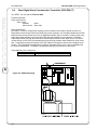
A.3
FIRELARM 2500 Operating Manual
Style Z (Class A) Module for NAC circuits (CAM)
UL LISTED: For use with the FireLarm 2500
Part No. 345-0234
TRANSIENT PROTECTED
BUILT IN 5.1K END OF LINE RESISTOR
POWER REQUIREMENTS IN ALARM: Approx. 25mA @ 24VDC from control panel notification
appliance circuit
The Model CAM Style Z (Class A) Module is designed to be used with the FireLarm 2500 Fire Control
Panels to convert a single Style Y (Class B) notification appliance circuit to a Style Z (Class A) circuit (one
module is required for each notification appliance circuit). The module is provided with snap track which is
mounted to the cabinet via double-sided foam tape and secured by two #6 sheet metal screws. The
module should be mounted in the area below the main circuit module as shown below so that the
terminals are accessible.
Figure A-3. CAM Module Wiring.
CAM
RED
+
BLACK
1
+
290-0029
2
+
3
-
Figure A-4. CAM Module Location.
TO INDICATING
APPLIANCE CIRCUIT
TERMINALS.
REMOVE EOL RESISTOR.
POLARITY SHOWN IS FOR
STANDBY (NON-ALARM)
CONDITION
4
A
-
USE FOAM TAPE TO MOUNT SNAP
TRACK IN CABINET AND SECURE
WITH TWO #6 SHEET METAL
SCREWS BEFORE MOUNTING CAM
MODULE IN SNAP TRACK
EXTERNAL
INDICATING
APPLIANCES
C
D
E
290-0023
B
A-3
CPG #2561255
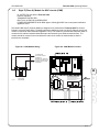
A.4
Contents
A
If the master box is provided with reset
supervisory contacts, the position of these
contacts may be supervised. When these
contacts are off normal LED D5 will
illuminate and the trouble outputs will be
activated.
Figure A-6. MBM Module Wiring.
24VDC
.3A MAX.
BLACK
RED
COM - (TERMINAL 43)
AUX PWER + (TERMINAL 44)
N.O. (TERMINAL 31)
YELLOW
TERMINAL 13
TERMINAL 14
GREEN
YELLOW
COM (TERMINAL 30)
TO AUXILIARY
ALARM CONTACTS
CONTACTS SHOWN
IN NORMAL STANDBY
CONDITION
5.1K
CONNECT INTO
SUPV. CIRCUIT
WITH 5.1K OHM
END-OF-LINE
RESISTOR (#024-4556)
HARRINGTON
OR GAMEWELL
MASTER FIRE
ALARM BOX
MBM
TRIP COIL
OPTIONAL RESET
SUPERVISION
CONTACTS
WHITE
5
Figure A-5. MBM.
A switch is provided to disable the unit so
that it will not trip the master box. Operation
of this switch will cause LED (D6) to
illuminate. To make this switch inoperative,
remove R42.
BLUE
4
The Model MBM is a local energy type Master Box actuating module for use with the FireLarm 2500 Fire
Control Panel. The unit can be mounted in the control panel housing, if space is available, or in a
separate housing (CPG #327-0089). The circuit between the module and the master box is supervised to
detect an open circuit. Terminals are provided for the connection of the master box reset supervisory
contacts.
ORANGE
3
Master Box Module (Model MBM)
UL LISTED: For use with the FireLarm 2500
Part No. 345-0235
Power requirements:
Standby: 30mA Max @24VDC
Alarm:
300 mA Max @24VCD
Master Box Coil Resistance: 14.5 ohms
Trouble output: Positive 2.5 V goes low in trouble and SPDT contacts transfer.
Contacts rated 2A@30VDC
Visual indicators: Yellow - Trouble/Disable
Yellow - Reset supervisory/ contacts off normal
Disable capability: Switch provided (can be made inoperative)
Size: 3"x5-1/2"
1
2
FIRELARM 2500 Operating Manual
RED
1 2 3 4
290-0016
A-4
ORANGE
ORANGE
CPG #2561255
FIRELARM 2500 Operating Manual
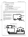
INSTALLATION
Mount the snap track with the double-sided tape provided and secure with two #6 sheet metal screws.
This module may be installed in a separate housing (HSI #327-0089) that is adjacent to and closenippled to the fire alarm control panel.
CAUTION:
This module must be installed in accordance with all applicable sections of NFPA 72, the National
Electrical Code, all local codes and any authority having jurisdiction.
Appendix normal text
Figure A-7. MBM Module Location.
POWER LIMITED SIDE
USE FOAM TAPE TO MOUNT SNAP
TRACK IN CABINET AND SECURE
WITH # 6 SHEET METAL SCREW
BEFORE MOUNTING MODULE IN
SNAP TRACK
MBM
MODULE
A
B
C
290-0024
NON-POWER LIMITED SIDE
POWER LIMITED SIDE
D
E
A-5
Contents
CPG #2561255
1
2
3
4
5
A
A-6
FIRELARM 2500 Operating Manual
CPG #2561255
FIRELARM 2500 Operating Manual
Appendix B. Smoke Detector Compatibility
HARRINGTON SIGNAL (MAX. NO. OF DETECTORS PER ZONE IS 25)
DET. MODEL
H511C
H511CXT
IDENTIFIER
S10A
S11A
BASE MODEL
IDENTIFIER
N/A
N/A
N/A
ESL (MAX. NO. OF DETECTORS PER ZONE IS 25)
DET. MODEL
429C
429CRT
429CSST
429CST
521B
521CRXT
711U
711UT
712U
713-5U
713-6U
721U
721UD
721UT
722U
731U
731UD
732U
IDENTIFIER
S10A
S11A
S11A
S11A
S10A
S10A
S10A
S10A
S10A
S10A
S10A
S10A
S10A
S10A
S10A
S11A
S11A
S11A
BASE MODEL
N/A
N/A
N/A
N/A
N/A
N/A
702, 702E, 701U, or 701E
702, 702E, 701U, or 701E
702, 702E, 701U, or 701E
701U, 702U, or 702E
701U, 702U, or 702E
702U or 702E
702U or 702E
702U or 702E
702U or 702E
702, 702E, 701RU, or 701RE
702U or 702E
702, 702E, 701RU, or 701RE
IDENTIFIER
N/A
S00 for all
SYSTEM SENSOR (BRK) (MAX. NO. OF DETECTORS PER ZONE IS 20)
DET. MODEL
1400
1451
2400
2400TH
2451
2451TH
IDENTIFIER
A
A
A
A
A
A
BASE MODEL
N/A
B401 B
N/A
N/A
B401 B
B401 B
IDENTIFIER
N/A
A
N/A
N/A
A
A
IF SYSTEM SENSOR DETECTORS ARE MIXED WITH OTHER MANUFACTURERS DETECTORS, DO NOT EXCEED 20 PER ZONE
APOLLO (MAX. NO. OF DECTORS PER ZONE IS 25)
DET. MODEL
55000-150
55000-151
55000-152
55000-153
55000-250
55000-350
55000-380
IDENTIFIER
55000-150
55000-151
55000-152
55000-153
55000-250
55000-350
55000-380
BASE MODEL
Any of the detectors at the left may use the following:
45681-200
45681-220
45681-227
45681-230
45681-231
45681-232
IDENTIFIER
B
45681-200
45681-220
45681-227
45681-230
45681-231
45681-232
C
COMPATIBILITY LISTINGS ARE NOT REQUIRED FOR 24 VOLT 4 WIRE DETECTORS
D
E
B-1
Contents
CPG #2561255
1
2
3
4
5
A
B
B-2
FIRELARM 2500 Operating Manual
CPG #2561255
FIRELARM 2500 Operating Manual
Appendix C. NAC Compatibility
The following devices are compatible with the FireLarm 2500.
CPG Signals
460 series sounders
SPLF, SPAF, SPHP, SPHH, SPHX series Powertone® speakers
ASLP, ASHP, ASHH, ASHX series amplified Powertone® speakers
MSLP, MSHP series mini speakers
450E series electronic horn
VST series strobe lights
FHEX series explosion proof horn
FSEX and LSEX series explosion proof strobes
V1971 series synchronized strobes
Harrington SIgnal
EMHG0 series mechanical horns
EHG0 series electronic horns
EHWPF0 series electro-mechanical outdoor horns
EMHWPF0 series outdoor electro-mechanical horns
MHG0 series mini horns
HSG1, HSG0 series electronic horn strobes
EHSG0, EMHSG0 series horn strobes
WEMHSG series outdoor horn strobes
MHSG0 series mini horn strobes
SSG1, SSG0, SSTG0, SSF0, SSWPF0 series strobes
2G1AVCMS, 4G0CMS strobe synchronizers
SMF0 series strobe synchronizers
4”LPSPKF0, 8”LPSPKF0 series speakers
ACVBF0, ACSSF0 series bells (AC)
DCVBF0 DCVBLCF0 DCSSBF0 series bells (DC)
ACCH, ACSSCHF0 series chimes (AC)
DCCHF0, DCCHLCF0, DCSSCHF0 series chimes (DC)
Amseco
SL24C, SDA24, RSD24, SL, CSL CSLB, CSLR series strobes
SDM10 sync module
SH, CSH, CSHB, SLB24, SHB24 series horn/strobes
CSS, SSC, SFH speaker strobes
FH series speakers
C
D
Gentex
GMH24 series mechanical horns
HG12 series electronic horns
GX90 series mini horns
GX90S Series mini horn strobes
SHG24, HS24, SHG24, GMS24 series horn strobes
WGMS24 series outdoor horn strobes
GES24, ST24, GXS, series strobes
AVS44, 4G0CMS strobe synchronizers
E
Faraday
6170 series electro-mechanical outdoor horns
6230, 6235 series outdoor electro-mechanical horns
2700, 2705 series strobes
5406 series strobe synchronizers
2953, 2954, 2955, 2958 series speakers
C-1
CPG #2561255
Contents
4415, 4495 series AC chimes
4765, 4775 series DC chimes
3431, 3436, 4496, 4411, 4416 series AC bells
4461, 4464, 4466, 4761, 4764, 4766, 4771, 4774, 4776 series DC bells
1
2
3
4
5
A
B
C
C-2
FIRELARM 2500 Operating Manual
CPG #2561255
FIRELARM 2500 Operating Manual
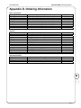
Appendix D. Ordering Information
Base Components
Model No.
2500-LCD
2500-LED
2500-MAN
12V6.5AH
12V8AH
12V10AH
12V15AH
12V25AH
Description
4 Zone Control Panel (red cabinet) – with LCD
4 Zone Control Panel (red cabinet) – no LCD
FireLarm 2500 Installation Instruction Manual
Battery, 12 Volt, 6.5 AH (2 required for 24V)
Battery, 12 Volt, 8.0 AH (2 required for 24V)
Battery, 12 Volt, 10 AH (2 required for 24V)
Battery, 12 Volt, 15 AH (2 required for 24V)
Battery, 12 Volt, 25 AH (2 required for 24V)
Stock No.
2500-LCD
2500-LED
2500-MAN
313-0170
313-0130
313-0254
313-0132
313-0265
Options
Model No.
BT
PAM-1
PAM-2
OPLCD
RALCD
CAM
MBM
ZDACT
Replacement Parts
Model No.
OPLCD
RMB
PWR
Description
Bezel Trim for Semi-Flush Mounting (black)
Relay (for 4-wire detector supervision)
Relay (for 4-wire detector supervision)
LCD Module for FireLarm 2500
Remote LCD Annunciator
RALCD Installation Instruction Manual
Style Z (Class A) Indicating Circuit Module
Master Box Module
Enclosure, 6x6x4, 18 gauge
Zonal Digital Alarm Comm. Transmitter
ZDACT Installation Instruction Manual
Description
LCD Module for FireLarm 2500
Main Circuit Board Module for FireLarm 2500
Replacement power supply
Stock No.
2500-BT
PAM-1
PAM-2
2500-OPLCD
2500-RALCD
2500-RALCD-M
2500-CAM
2500-MBM
2500-CAB
2500-ZDACT
2500-ZDACT-M
Stock No.
2500-OPLCD
2500-RMB
2500-PWR
D
E
D-1
Contents
CPG #2561255
1
2
3
4
5
A
B
C
D
D-2
FIRELARM 2500 Operating Manual
CPG #2561255
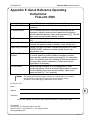
FIRELARM 2500 Operating Manual
Appendix E. Quick Reference Operating
Instructions
FireLarm 2500
Normal Standby
Alarm Conditions
To Silence Alarm
To Reset an Alarm
Trouble Conditions
Supervisory Condition
To Silence Trouble
Devices
To Test Alarm
Green AC indicator on. All other indicators off.
Red zone indicator on. Audible/visual signaling indicator
operating
Do not silence alarm until it has been determined that an
emergency situation does not exist (panel must be reset to
silence waterflow alarms). Open cover and press . This will
also cause the bell trouble indicator to flash.
After condition that caused alarm has been corrected, press
.
Yellow SYSTEM TROUBLE indicator and buzzer on. Yellow
indicator for specific trouble on (battery, zone, trouble, etc.)`
Yellow SYSTEM TROUBLE indicator and buzzer on. Yellow
SUPERVISORY indicator on (valve closed, low air, low
temperature, etc.)
Open cover and press . The panel automatically restores
to normal when the trouble condition has been corrected.
Some trouble conditions require pressing for restoration.
Note: The problem must be corrected as soon as possible as
this may make system inoperative. Contact your service
organization if necessary.
Notify building occupants (if a fire department or other
monitoring agency, such as a Central Station alarm company,
monitors alarms, they must also be notified). Open cover,
press and hold for 2 seconds.
This system should be thoroughly inspected on a regular basis in accordance
with the NFPA-72 National Fire Alarm Code and the authority having
jurisdiction. Contact the agency listed below for this service.
For Service, Call
Name:
E
Address:
Telephone:
INSTALLER: FRAME THIS SHEET AND PLACE ADJACENT TO CONTROL PANEL
CPG Signals
2519 4th Ave., P.O. Box 590, Moline, IL 61265
(800) 577-5758 / (309) 762-0731 / FAX (309) 762-8215
www.cpglifesafety.com
E-1
Contents
CPG #2561255
1
2
3
4
5
A
B
C
D
E
E-2
FIRELARM 2500 Operating Manual