1
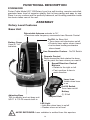
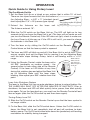
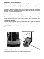
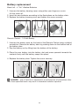
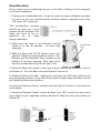
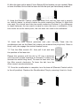
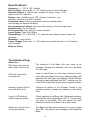
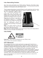
Instruction
manual
ESPAÑOL: PÁGINA 13
FRANÇAISE : PAGE 27
Rotary Level
Self-Leveling, Remote-Controlled
Laser Level
Model LR1100
U. S. Patents 5680208, 5903345. Engineered
in USA. Manufactured in China.
To learn more about Porter-Cable
visit our website at:
http://www.porter-cable.com
IMPORTANT
Please make certain that the person who is
to use this equipment carefully reads and
understands these instructions before
starting operations.
The Model and Serial No. plate is located on the main
housing of the tool. Record these numbers in the
spaces below and retain for future reference.
Model No. ______________________________________
Type ___________________________________________
Serial No. _______________________________________
Copyright © 2002 Porter-Cable Corporation
Part No. 905069 - 04-15-02
GENERAL SAFETY RULES
ELECTRICAL SAFETY
1. Use battery operated rotary level with alkaline batteries only. Use of
any other batteries may permanently damage the rotary level.
PERSONAL SAFETY
1. Stay alert, watch what you are doing, and use common sense when
operating a laser. Do not use rotary level while tired or under the
influence of drugs, alcohol, or medication. A moment of inattention while
operating a laser may result in personal injury.
2. Use safety equipment. Eye protection, dust mask, non-skid safety
shoes, hard hat, or hearing protection must be used for appropriate
conditions.
3. Prolonged eye contact with laser beams can cause eye irritation and
injury to the eye. Never stare direcly into beam or view with optical
instruments. Avoid prolonged eye contact with laser beams. Laser beam
contact with the eyes can also cause temporary flash blindness, which can
cause the user to be distracted, which can lead to accidents.
4. Do not aim the laser beams at others.
TOOL USE AND CARE
1. Do not use rotary level if switch does not turn it on or off. A laser that
cannot be controlled with the switch is dangerous and must be repaired.
2. Store idle rotary level out of reach of children and other untrained
persons. Rotary level should only be used by trained users.
3. Use only accessories that are recommended by the manufacturer for
your model. Accessories that may be suitable for one rotary level may create
a risk of injury when used on another rotary level.
SERVICE
1. Rotary Level service must be performed only by qualified repair
personnel. Service or maintenance performed by unqualified personnel may
result in a risk of injury.
2. When servicing a rotary level, use only identical replacement parts.
Follow instructions in the Maintenance Section of this manual. Use of
unauthorized parts or failure to follow Maintenance Instructions may create a
risk of shock or injury.
SPECIFIC SAFETY RULES
1. Be aware that the rotary level is always in an operating condition,
because it does not have to be plugged into an electrical outlet. Always set
the switch to the “OFF” position when installing or removing the batteries.
2. IMPORTANT: These labels are attached to every rotary level. They
are not to be removed or defaced.
3. CAUTION: Use of controls, adjustments or procedures other than those
specified herein may result in laser radiation exposure.
4.
AVOID EXPOSURE: Laser radiation is emitted from this aperture.
5.
WARNING: There are certain applications for which this rotary
level was designed. Porter-Cable strongly recommends that this rotary level
NOT be modified and/or used for any application other than for which it was
designed. If you have any questions relative to its application DO NOT use
the rotary level until you have written Porter-Cable and we have advised you.
Technical Service Manager
Porter-Cable Corporation
4825 Highway 45 North
Jackson, TN 38305
2
FUNCTIONAL DESCRIPTION
FOREWORD
Porter-Cable Model LR 1100 Rotary Level is a self-leveling, remote-controlled,
precision laser level of superior quality that is time-saving and easy to use.
Place it on any surface and the perfectly balanced, self-leveling pendulum inside
the device takes care of the rest.
ASSEMBLY
Rotary Level Features
Base Unit
Retractable Antenna extends to 16"
• Receives radio frequency commands from Remote Control
On/Off- for Base Unit
• Turns base unit electronics on/off
• Protects laser optics when closed
• Locks down leveling mechanism
when closed
Battery Cover
Uses (4) "AA"
batteries
Line Generation Feature - On/Off Switch
Remote Control
Radio transmitter that rotates the base
unit to point the laser where you want it!
Speed/Direction Control
Buttons
• Rotate to the right or left
• Fast, medium & slow in
each direction
Laser Icon
Visible when laser
is on
On/Off Switch
Turns laser on/off
Battery
(1) 9-Volt
Adjusting Base
Tilts to roughly level out base unit
5/8-11 & 1/4-20 mounts built-in
Lanyard Hole
LED Light
• Indicates when laser is on/off
• Flashes when out of level
AVOID EXPOSURE: Laser radiation is emitted from this aperture.
3
OPERATION
Quick Guide to Using Rotary Level
The One Minute Set-Up
1. Set the Base Unit up on a tripod or any surface that is within 10° of level.
There are two tripod mounts built into the bottom of
the Adjusting Base - a 5/8" x 11 (standard transit
level tripod) and 1/4" x 20 (camera-type tripod).
2. Extend the Antenna on
The Antenna extends 16".
the
base
unit
by
pulling
up
gently.
3. Slide the On/Off switch on the Base Unit up. The LED will light up for two
seconds to let you know the Base Unit is on. (The laser will not come on until
you turn the Remote Control on) If the LED does not light, check to make sure
the Lens Cover is all the way up. If the LED is still not lit, you need to change
the batteries in the Base Unit.
4. Turn the laser on by sliding the On/Off switch on the Remote
Control down so that the laser symbol is exposed.
5. The laser and LED will blink on and off if the Base Unit is out-of-level. If this
occurs, roughly level out the Base Unit by moving it on the Adjusting Base
until the laser stops blinking. Rotary Level is self-leveling within a +/-10°
range.
Rotate 360 °to
6. Using the Remote Control, rotate the base unit a
full 360° (preferably on medium speed - the
second arrow in from either side of the Remote
Control). If the laser or LED blinks at any time
during this rotation stop and adjust the Base Unit
on its Adjusting Base until the laser stops
blinking, then repeat your 360° rotation from that
point.
make sure the
laser does not
blink, and you're
set to go!
Laser Auto Shutdown Feature
The laser in the Base Unit has an auto-shutdown feature to extend battery life.
THE LASER WILL SHUT OFF AFTER FIVE MINUTES OF INACTIVITY. Prior to
shutdown, the laser and LED will blink quickly twice, pause, then blink quickly
twice again. To turn the laser back on, you must turn the Remote Control off and
then on again (slide the On/Off switch up and then down again).
Turning Rotary Level Off
8. Slide the On/Off switch on the Remote Control up so that the laser symbol is
no longer visible.
9. On the Base Unit, slide the On/Off switch down. Unless the On/Off switch is
down, the Base Unit is not completely shut off and will continue to drain
battery power. The On/Off switch also locks down the (pendulum) self-leveling
mechanism for stability during transport.
4
Using the Remote Control
The Remote Control is one of the features that makes Rotary Level unique in the
field of laser leveling systems. Using the Remote Control, you can control the
rotation of the Base Unit from up to 100 feet away! You don't even have to be "in
sight" of the Base Unit because the Remote Control operates on radio frequency.
The speed / direction buttons control the rotation of the precision step motor
inside the Base Unit - which simply means that you put the laser dot right where
you need it for marking or measurement.
By pressing the speed / direction buttons, you can rotate the Base Unit 360°
clockwise (right) or counterclockwise (left).
There are three speeds of rotation - Fast, Medium, and Slow (very slow). The
slowest speed is most helpful when you want the laser dot to hit a specific spot.
Finding The Laser Dot
Using the speed / direction buttons on the Remote Control, rotate the Base Unit
until you see the LED on the Base Unit straight on (at its brightest). It is easiest
to sweep the laser dot across walls or other flat surfaces. Your body can also be
used as a target if operating the unit in an open field.
DANGER: Never look directly into the laser source as this may cause eye
damage.
Speed/Direction Control Buttons
If laser icon
is showing,
laser is ON
Fast
Medium
Slow
NOTE: Multiple Remote Controls - can be used with one Base Unit. Additional /
Replacement Remote Control can be purchased separately.
5
Battery replacement
Base Unit - 4 "AA" Alkaline Batteries
1. Unscrew the battery housing cover using either your fingers or a coin.
Lift the cover off.
2. Insert the new batteries according to the illustrations on the battery slots.
3. Replace the battery housing cover and tighten the screw securely.
Remote Control - 1 9-Volt Battery
1. Unscrew the battery door on the back of the Remote Control using a slotted
screwdriver. Remove the battery door by pushing down on the bottom half of
the battery door.
2. Pop the battery out by lifting from the bottom of the battery.
3. Place the new battery into the battery slot and press upwards towards the
contacts firmly until the battery snaps into place.
4. Replace the battery door. Tighten the screw securely.
1.
2.
3.
DANGER: - use of controls or adjustments or performance of procedures other
than those specified herein may result in hazardous radiation exposure.
6
Recalibration
Rotary Level can be recalibrated by you, in the field. If Rotary Level is dropped,
you should recalibrate.
1. Choose your recalibration site. To get the most accurate calibration possible,
it is best to use two vertical (plumb) surfaces directly opposite each other,
100' apart (50' minimum).
The recalibration process
should be done on a level
surface so that the Base Unit
does not have to be readjusted on its base
during calibration.
2. Make sure the laser is off (Remote Control
switch is in the off position - no laser icon
showing).
Recalibration
Plug
3. Slide the Base Unit On/Off switch to the "on"
position. Slide the line generation switch "Off".
Remove the Recalibration Plug, located at the
bottom of the laser opening. Take care not to
lose the recalibration plug as you pop it out.
4. Place the Base Unit about 5' from one of your two vertical surfaces. This will
be Surface A. Turn the Base Unit and Remote Control on.
5. Rotate the Base Unit 360°, making sure the laser and LED don't blink at any
time during the rotation. If they blink at any point, simply adjust the Base Unit on
the Adjusting Base and continue.
6. Using the Remote Control, position the laser dot on Surface A and mark the
dot location.
7. Using the Remote Control, rotate the Base Unit 180° so that the laser dot is
now visible on your opposing surface, Surface B. Mark the laser dot position on
Surface B.
7
8. Move the base unit to about 5' from Surface B (the location you just marked). Raise
or lower the Base Unit so that the laser dot hits the spot you have already marked.
9. Using the Remote Control, rotate the Base Unit until the laser dot is exactly
on, directly above, or directly below the point marked on Surface A. Mark this
new spot. You should now have two spots marked on Surface A. Any difference
in height between the two marks is equal to twice the error in calibration. If the
two marks are at the same point, the unit does not need to be calibrated.
10. Insert the Allen wrench (provided with your Carrying Case) into the
recalibration port on the Base Unit (where you removed the plug from). Press in
firmly until you engage the socket headed screw.
11. Turn the Allen wrench 45°, then pull it out and note
the position of the laser dot.
Repeat this process until the dot is 1/2 way in between
your first and second markings on Surface A (where you
started this whole thing from). To raise the laser dot, turn
the Allen wrench clockwise. To lower the dot, turn the
Allen wrench counterclockwise.
12. Once the recalibration is complete, turn the laser off (Remote Control switch
in the off position). Replace the Recalibration Plug by pressing it back in firmly.
8
Specifications
Accuracy: +/- 1/8" @ 100' (radius)
Self-leveling: Level range +/- 10°; flashing out-of-level indicator
Remote Control: 3 speeds (low, medium & high); range – 100'
radius and 200' diameter
Range: Laser visibility up to 100' (indoor & outdoor – no
detector required); full 360° rotation
Pendulum Lock: Protects pendulum during transportation
and storage for added durability
Line Generation Feature: Converts laser beam to line of bright dots
Recalibration: On the jobsite
Environmental: Dust, dirt and water resistant
Laser Diode: Class IIIA 635nm
Tripod Mount: 1/4" x 20 & 5/8" x 11, (can be used without tripod; tripod not
included)
Warranty: 1 year limited
Power Supply: Base unit – 4 “AA” batteries; remote control – 9 volt battery
(not included)
Made In China
Troubleshooting
When the…
LED does not come on
when Lens Cover is up.
The batteries in the Base Unit may need to be
changed. Change the batteries, then turn the Base
Unit on again.
LED and Laser blink
continuously.
Laser is out-of-level, or has been knocked out-oflevel. Move the Base Unit on the Adjusting Base until
both the LED and Laser quit blinking. Use the Remote
Control to rotate the Base Unit 360°, making sure the
Laser/LED do not blink at any time during the rotation.
Remote Control will not
drive the Base Unit.
Change the battery in the Remote Control. If the
problem persists, change the batteries in the Base
Unit.
Laser & LED shut off
without warning blinks.
Check batteries in the Base Unit. Prolonged exposure
to extremely high temperatures (120° F +) may cause
the laser to overheat. This will cause the selfprotection circuit in the Base Unit to shut down.
Base Unit will not move
on Adjusting Base.
The Base Unit has been mounted to a screw longer
than 5/8". This could cause damage to the Adjusting
Base.
9
Line Generating Feature
You have just purchased your Self-Leveling, Remote Controlled Laser,
Rotary Level with the new line-generating feature. The following outlines the
operation of the feature with your Rotary Level.
The line-generating feature converts Rotary Level’s single laser dot into a line
of bright dots, designed specifically for interior leveling applications. Turn
the line generation feature switch
“ON”. A horizontal, stationary line of
bright laser dots will appear if the
Rotary Level is level and a horizontal,
flashing line of bright laser dots will
appear if the Rotary Level is not level.
Reposition the Rotary Level within its
self-leveling range of +/- 10 degrees
to achieve a stationary, horizontal
level line of laser dots. The line can
then be positioned around the
worksite with the Rotary Level remote
control.
Note: The center section of the line
yields the brightest dots. Dots at the
far extreme will appear fainter.
Note: Be sure to turn the Rotary Level off during storage and transportation.
Failure to do so will affect the battery life.
User Safety
Important: These labels are attached to every Rotary Level.
They are not to be removed or defaced.
FCC Statement
This equipment has been tested and found to comply with the limits for a
Class B digital device, pursuant to Part 15 of the FCC Rules. These limits are
designed to provide reasonable protection against harmful interference in a
residential installation. This equipment generates, uses and can radiate radio
frequency energy and, if not installed and used in accordance with the
instructions, may cause harmful interference to radio communication. However,
there is no guarantee that interference will not occur in a particular installation.
If this equipment does cause harmful interference to radio or television
reception, which can be determined by turning the equipment off and on, the
user is encouraged to try to correct the interference by one or more of the
following measures:
10
- Reorient or relocate the receiving antenna
- Increase the separation between the equipment and receiver
- Consult the dealer or an experienced radio/TV technician for help.
This device complies with Part 15 of the FCC Rules. Operation is subject to the
following two conditions:
(1) This device may not cause harmful interference, and
(2) This device must accept any interference received, including interference
that may cause undesired operation.
IMPORTANT: Changes or modifications to this product not authorized by
Porter-Cable Corporation, could void the FCC Certification and negate your
right to operate the product.
Porter-Cable Corporation
4825 Highway 45 North
Jackson, TN 38305
Copyright © 2002, All rights reserved.
GENERAL MAINTENANCE
KEEP TOOL CLEAN
All plastic parts should be cleaned with a soft damp cloth. NEVER use
solvents to clean plastic parts. They could very possibly dissolve or otherwise
damage the material.
FAILURE TO OPERATE
Should your laser square fail to operate, make sure batteries are charged and
properly installed.
BATTERY
The batteries will discharge if stored for long periods of time, and may require
replacement before use.
SERVICE AND REPAIRS
All quality tools will eventually require servicing or replacement of parts due
to wear from normal use. These operations, should ONLY be performed by
either an AUTHORIZED PORTER-CABLE SERVICE STATION or a PORTERCABLE • DELTA FACTORY SERVICE CENTER. All repairs made by these
agencies are fully guaranteed against defective material and workmanship.
We cannot guarantee repairs made or attempted by anyone other than these
agencies.
Should you have any questions about your laser square, feel free to write us
at any time. In any communications, please give all information shown on the
nameplate of your laser square (model number, type, serial number, etc.).
11
ACCESSORIES
A complete line of accessories is available from your Porter-Cable
Supplier, Porter-Cable • Delta Factory Service Centers, and Porter-Cable
Authorized Service Stations. Please visit our Web Site www.portercable.com for a catalog or for the name of your nearest supplier.
WARNING: Since accessories other than those offered by PorterCable have not been tested with this product use of such
accessories could be hazardous. For safest operation, only PorterCable recommended accessories should be used with this product.
905898
905899
905900
905901
905907
905972
REPLACEMENT PARTS LIST
ANTENNA
REMOTE CONTROL
REMOTE CONTROL BATTERY COVER
BATTERY COVER SCREW
BATTERY COVER
CALIBRATION PORT PLUG
PORTER-CABLE LIMITED
ONE YEAR WARRANTY
Porter-Cable warrants its Professional Power Tools for a period of one year from the date of original
purchase. We will repair or replace at our option, any part or parts of the product and accessories
covered under this warranty which, after examination, proves to be defective in workmanship or
material during the warranty period. For repair or replacement return the complete tool or accessory,
transportation prepaid, to your nearest Porter-Cable Service Center or Authorized Service Station.
Proof of purchase may be required. This warranty does not apply to repair or replacement required
due to misuse, abuse, normal wear and tear or repairs attempted or made by other than our Service
Centers or Authorized Service Stations.
ANY IMPLIED WARRANTY, INCLUDING THE IMPLIED WARRANTIES OF MERCHANTABILITY AND
FITNESS FOR A PARTICULAR PURPOSE, WILL LAST ONLY FOR ONE (1) YEAR FROM THE DATE
OF PURCHASE.
To obtain information on warranty performance please write to: PORTER-CABLE CORPORATION,
4825 Highway 45 North, Jackson, Tennessee 38305; Attention: Product Service. THE FOREGOING
OBLIGATION IS PORTER-CABLE’S SOLE LIABILITY UNDER THIS OR ANY IMPLIED WARRANTY
AND UNDER NO CIRCUMSTANCES SHALL PORTER-CABLE BE LIABLE FOR ANY INCIDENTAL OR
CONSEQUENTIAL DAMAGES. Some states do not allow limitations on how long an implied warranty
lasts or the exclusion or limitation of incidental or consequential damages, so the above limitation or
exclusion may not apply to you.
This warranty gives you specific legal rights and you may also have other legal rights which vary from
state to state.
12
PORTER-CABLE • DELTA SERVICE CENTERS
(CENTROS DE SERVICIO DE PORTER-CABLE • DELTA)
(CENTRE DE SERVICE PORTER-CABLE • DELTA)
Parts and Repair Service for Porter-Cable • Delta Power Tools are Available at These Locations
(Obtenga Refaccion de Partes o Servicio para su Herramienta en los Siguientes Centros de Porter-Cable • Delta)
(Locations où vous trouverez les pièces de rechange nécessaires ainsi qu’un service d’entretien)
ARIZONA
Tempe 85282 (Phoenix)
2400 West Southern Avenue
Suite 105
Phone: (602) 437-1200
Fax: (602) 437-2200
CALIFORNIA
Ontario 91761 (Los Angeles)
3949A East Guasti Road
Phone: (909) 390-5555
Fax: (909) 390-5554
San Leandro 94577 (Oakland)
3039 Teagarden Street
Phone: (510) 357-9762
Fax: (510) 357-7939
COLORADO
Arvada 80003 (Denver)
8175 Sheridan Boulevard, Unit S
Phone: (303) 487-1809
Fax: (303) 487-1868
FLORIDA
Davie 33314 (Miami)
4343 South State Rd. 7 (441)
Unit #107
Phone: (954) 321-6635
Fax: (954) 321-6638
Tampa 33609
4538 W. Kennedy Boulevard
Phone: (813) 877-9585
Fax: (813) 289-7948
GEORGIA
Forest Park 30297 (Atlanta)
5442 Frontage Road, Suite 112
Phone: (404) 608-0006
Fax: (404) 608-1123
ILLINOIS
Addison 60101 (Chicago)
400 South Rohlwing Road
Phone: (630) 424-8805
Fax: (630) 424-8895
Woodridge 60517 (Chicago)
2033 West 75th Street
Phone: (630) 910-9200
Fax: (630) 910-0360
MARYLAND
Elkridge 21075 (Baltimore)
7397-102 Washington Blvd.
Phone: (410) 799-9394
Fax: (410) 799-9398
MASSACHUSETTS
Braintree 02185 (Boston)
719 Granite Street
Phone: (781) 848-9810
Fax: (781) 848-6759
Franklin 02038 (Boston)
Franklin Industrial Park
101E Constitution Blvd.
Phone: (508) 520-8802
Fax: (508) 528-8089
MISSOURI
North Kansas City 64116
1141 Swift Avenue
P.O. Box 12393
Phone: (816) 221-2070
Fax: (816) 221-2897
St. Louis 63119
7574 Watson Road
Phone: (314) 968-8950
Fax: (314) 968-2790
NEW YORK
Flushing 11365-1595 (N.Y.C.)
175-25 Horace Harding Expwy.
Phone: (718) 225-2040
Fax: (718) 423-9619
NORTH CAROLINA
Charlotte 28270
9129 Monroe Road, Suite 115
Phone: (704) 841-1176
Fax: (704) 708-4625
MICHIGAN
Madison Heights 48071 (Detroit)
30475 Stephenson Highway
Phone: (248) 597-5000
Fax: (248) 597-5004
OHIO
Columbus 43214
4560 Indianola Avenue
Phone: (614) 263-0929
Fax: (614) 263-1238
Cleveland 44125
8001 Sweet Valley Drive Unit #19
Phone: (216) 447-9030
Fax: (216) 447-3097
OREGON
Portland 97230
4916 NE 122 nd Ave.
Phone: (503) 252-0107
Fax: (503) 252-2123
PENNSYLVANIA
Willow Grove 19090
520 North York Road
Phone: (215) 658-1430
Fax: (215) 658-1433
TEXAS
Carrollton 75006 (Dallas)
1300 Interstate 35 N, Suite 112
Phone: (972) 446-2996
Fax: (972) 446-8157
Houston 77055
West 10 Business Center
1008 Wirt Road, Suite 120
Phone: (713) 682-0334
Fax: (713) 682-4867
WASHINGTON
Auburn 98001 (Seattle)
3320 West Valley HWY, North
Building D, Suite 111
Phone: (253) 333-8353
Fax: (253) 333-9613
MINNESOTA
Minneapolis 55429
5522 Lakeland Avenue North
Phone: (763) 561-9080
Fax: (763) 561-0653
Authorized Service Stations are located in many large cities. Telephone 800-487-8665 or 731-541-6042 for assistance locating one. Parts
and accessories for Porter-Cable • Delta products should be obtained by contacting any Porter-Cable • Delta Distributor, Authorized
Service Center, or Porter-Cable • Delta Factory Service Center. If you do not have access to any of these, call 888-848-5175 and you will
be directed to the nearest Porter-Cable • Delta Factory Service Center. Las Estaciones de Servicio Autorizadas están ubicadas en
muchas grandes ciudades. Llame al 800-487-8665 ó al 731-541-6042 para obtener asistencia a fin de localizar una. Las piezas y los
accesorios para los productos Porter-Cable • Delta deben obtenerse poniéndose en contacto con cualquier distribuidor Porter-Cable •
Delta, Centro de Servicio Autorizado o Centro de Servicio de Fábrica Porter-Cable • Delta. Si no tiene acceso a ninguna de estas
opciones, llame al 888-848-5175 y le dirigirán al Centro de Servicio de Fábrica Porter-Cable • Delta más cercano. Des centres de service
agréés sont situés dans beaucoup de grandes villes. Appelez au 800-487-8665 ou au 731-541-6042 pour obtenir de l’aide pour en
repérer un. Pour obtenir des pièces et accessoires pour les produits Porter-Cable • Delta, s’adresser à tout distributeur Porter-Cable •
Delta, centre de service agréé ou centre de service d’usine Porter-Cable • Delta. Si vous n’avez accès à aucun de ces centres, appeler
le 888-848-5175 et on vous dirigera vers le centre de service d’usine Porter-Cable • Delta le plus proche.
CANADIAN PORTER-CABLE • DELTA SERVICE CENTERS
ALBERTA
Bay 6, 2520-23rd St. N.E.
Calgary, Alberta
T2E 8L2
Phone: (403) 735-6166
Fax: (403) 735-6144
MANITOBA
1699 Dublin Avenue
Winnipeg, Manitoba
R3H 0H2
Phone: (204) 633-9259
Fax: (204) 632-1976
BRITISH COLUMBIA
8520 Baxter Place
Burnaby, B.C.
V5A 4T8
Phone: (604) 420-0102
Fax: (604) 420-3522
ONTARIO
505 Southgate Drive
Guelph, Ontario
N1H 6M7
Phone: (519) 836-2840
Fax: (519) 767-4131
QUÉBEC
1515 Ave.
St-Jean Baptiste,
Québec, Québec
G2E 5E2
Phone: (418) 877-7112
Fax: (418) 877-7123
1447, Begin
St-Laurent, (Montréal), Québec
H4R 1V8
Phone: (514) 336-8772
Fax: (514) 336-3505
The following are trademarks of PORTER-CABLE • DELTA (Las siguientes son marcas registradas de PORTER-CABLE • DELTA S.A.) (Les
marques suivantes sont des marques de fabriquant de la PORTER-CABLE • DELTA): BAMMER®, LASERLOC®, OMNIJIG®, POCKET CUTTER®,
PORTA-BAND®, PORTA-PLANE®, PORTER-CABLE®, QUICKSAND®, SANDTRAP®, SAW BOSS®, SPEED-BLOC®, SPEEDMATIC®,
SPEEDTRONIC®, STAIR-EASE®, THE PROFESSIONAL EDGE®, THE PROFESSIONAL SELECT®, TIGER CUB®, TIGER SAW®, TORQ-BUSTER®,
VERSA-PLANE®, WHISPER SERIES®, DURATRONIC™, FRAME SAW™, INNOVATION THAT WORKS™, JETSTREAM™, MICRO-SET™,
MORTEN™, NETWORK™, RIPTIDE™, TRU-MATCH™, WOODWORKER’S CHOICE™, THE AMERICAN WOOD SHOP™ (design) , AUTOSET™, B.O.S.S.™, BUILDER’S SAW™, CONTRACTOR’S SAW™, DELTA™, DELTACRAFT™, HOMECRAFT™, JET-LOCK™, KICKSTAND™,
THE LUMBER COMPANY™ (design). MICRO-SET™, Q3™, QUICKSET II™, QUICKSET PLUS™, SAFEGUARD II™, SANDING CENTER™,
SIDEKICK™, UNIFENCE™, UNIGUARD™, UNIRIP™, UNISAW™, VERSA-FEEDER™ , THIN-LINE™, TPS™, Emc²™.
Trademarks noted with ™ and ® are registered in the United States Patent and Trademark Office and may also be registered in other countries.
Las Marcas Registradas con el signo de ™ y ® son registradas por la Oficina de Registros y Patentes de los Estados Unidos y también pueden
estar registradas en otros países. Marques déposées, indiquées par la lettre ™ et ®, sont déposées au Bureau des brevets d’invention et
marques déposées aux Etats-Unis et pourraient être déposées aux autres pays.
Printed in U.S.A.