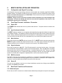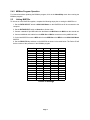
1
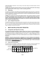
MX8700 and MX8750
D I G I TA L C R O S S O V E R / S I G N A L P R O C E S S O R S
OWNER’S MANUAL
1.
INTRODUCTION
Congratulations on purchasing the latest sound reinforcement innovation from Eastern Acoustic Works.
The MX8700 and MX8750 digital processors are built upon the same fundamental design principles that
EAW has upheld since the introduction of the original MX Series Processors in the 1980’s. These new
products redefine EAW’s signal processing by drawing on the latest advances in digital technology to provide optimum signal processing and management of EAW loudspeaker systems.
1.1
MX8700 Description
The EAW MX8700 Close Coupled Electronic Processor is a two-channel, four-way electronic crossover and
loudspeaker system processor intended for use with both installed and portable systems. The MX8700 provides factory preset configuration, crossovers, equalization, limiting, and other appropriate signal processing
for particular EAW loudspeakers listed on a rear panel label. These parameters cannot be inadvertently or
purposefully modified by the user. This protects the system from improper settings that may cause less than
optimum performance from or damage to the loudspeakers. It is possible to download factory provided settings to the MX8700 for different EAW loudspeaker systems by using EAW’s MXLoader program.
NOTE: It is necessary to set the processor’s gain for the correct limiting thresholds and for special subwoofer settings. See the Section 4.2 for details about how to do this.
1.2
MX8750 Description
The EAW MX8750 Close Coupled Electronic Processor is a two input, eight output electronic crossover
and loudspeaker system processor intended for use with both installed and portable systems. All control
and operation of the processor is done using EAW’s MXWare software program that runs on an IBM compatible computer using the Windows 98, 2000, ME, or NT operating system. MXWare was not written for
Windows 95.
Up to 16 MX8750 processors can be linked together so that all processors can be controlled by the
MXWare program.
2.
UNPACKING
2.1
Shipping Damage
After unpacking if there is damage to the processor, save the packing materials for the carrier’s inspection, notify the carrier immediately, and file a shipping damage claim.
Although EAW will help in any way possible, it is always the responsibility of the receiving party to file any
shipping damage claim. The carrier will help prepare and file this claim.
2.2
Returning a Processor to EAW
If the processor must be returned, contact EAW for a Return Authorization. Use the original shipping carton and packing materials. If the shipping carton is damaged, contact EAW for a new carton. EAW will
not be responsible for damage caused by inadequate packing.
3.
MX8700 / MX8750 CONNECTIONS
3.1
AC Mains Connections
The operating voltage for the AC mains is listed in the rear of the processor.
If the mains voltage is listed as 120 V, be sure that your AC mains voltage is somewhere between 90-125
VAC, 50-60 Hz.
Page 1
If the mains voltage is listed 240 V, be sure that your AC mains voltage is somewhere between 180 and
250 VAC, 50-60 Hz.
DANGER: Operating this equipment with the incorrect mains voltage selected will cause damage
to the equipment and/or result in injury or death to operating personnel.
3.2
Grounding
The chassis of this product is grounded through the grounding conductor of the power cord. To avoid electric shock, plug the power cord into a properly wired and grounded receptacle before making any connections to the product. A protective ground connection, by way of the grounding conductor in the power
cord, is essential for safe operation.
DANGER: This equipment must be operated with the power cord grounding conductor connected
to a properly grounded AC outlet. Do not disconnect, “lift”, or otherwise remove this ground connection. If the protective ground connection is lost, all accessible conductive parts, including
knobs and controls that may appear to be insulated, can render an electric shock that can cause
injury or death to operating personnel.
3.3
Input / Output Connections
The MX8700 and MX8750 use XLR female and male connectors for their audio input and output connections. Pin 1 of each connector connects directly to the chassis and is used for the cable shield connection. Pin 2 and pin 3 are the balanced input/output connections, with pin 2 being the hot (plus) connection
and pin 3 being the cold (minus) connection.
4
MX8700 INSTALLATION AND OPERATION
4.1
Configuration and Signal Processing
The configuration and signal processing parameters are preset at the factory for a specific loudspeaker or
loudspeaker and subwoofer combination. A label is affixed to the rear panel of the MX8700 stating the
model number(s) for which it is configured and the uses for each output. No user changes are possible for
the configuration and signal processing parameters for any preset. If a different loudspeaker or loudspeaker/subwoofer combination is to be used, a different preset must be loaded into the MX8700. See
Section 4.4.
WARNING: Using the wrong preset with a loudspeaker can result in damage to the loudspeaker.
Be sure the correct preset is loaded into the MX8700 for your loudspeaker. If in doubt about what
preset is actually loaded, simply obtain the correct preset for the loudspeakers you are using from
the EAW web site: http://www.eaw.com/. and go to the “Downloads” page. Then load the preset
into the MX8700 using the MXLoader program.
4.1.1
Output Connection Details
SB150/JF560z
OUTPUTS:
S L M H
OUTPUT USE:
sub low n/c
hi
SB150/JF560z
S L M H
sub low n/c
Example Configuration Label
Page 2
hi
451xxx
MODEL #s:
451xxx
The configuration for the MX8700 is shown on the label affixed at the factory. Connect the outputs to the
amplifiers feeding the loudspeaker sections listed in the label. An example label is shown below.
EAW PART #s
MODEL NUMBERS: These are the particular loudspeakers and subwoofers for which the MX8700 is
configured.
OUTPUTS: These correspond to the output connectors and are listed on the label as:
S = SUB
L = LOW
M = MID
H = HIGH
OUTPUT USE: The uses are listed on the label as:
sub = subwoofer (for separate subwoofer system)
low = low frequency (for 2-way and 3-way loudspeakers)
l/m = low/mid (for 3-way loudspeakers with a passive low/mid crossover)
mid = mid frequency (for 3-way loudspeakers)
m/h = mid/high (for 3-way loudspeakers with a passive mid/high crossover)
hi = high frequency (for 2-way and 3-way loudspeakers)
n/c = no connection. The output is not used for this configuration.
EAW PART #s: These are the MX8700 part numbers for the factory loaded presets for each channel.
4.2
Front Panel Controls / Indicators
4.2.1
Power LED
The POWER LED indicates that the unit is powered and turned on. The power switch is located on the
rear panel.
4.2.2
Input Headroom Indicator
The INPUT headroom indicator is a six-segment peak-responding bar graph that indicates the signal level
from -20 dBu to clipping. The headroom indicator monitors the input to the A/D converter, after the input
level control. Ideally, you want the highest peak level to illuminate the +12 dBu segment, but not the CLIP
segment.
You can set the level lower than this, but understand that you are reducing the signal-to-noise ratio.
4.2.3
Sub Mode Switches
There are three “SUB” switches that match the operation of the MX8700’s SUB outputs to the operating
conditions of the subwoofers.
Ch 1 SUB and Ch 2 SUB
adj - Adjacent mode: This mode provides a true low pass / high pass crossover between the LOW
frequency output and SUB output. Use this mode when the main system and the subwoofers are
arrayed together. This configuration typically provides the flattest overall response.
off - Off Mode: In this mode the SUB output is turned off. The LOW frequency output is reconfigured
for extended bandwidth operation by lowering the high pass filter frequency and adjusting equalization
and protection parameters.
dis - Distant Mode: This mode overlaps the crossover frequencies between the SUB and LOW outputs. Use this mode when the subwoofers are located remotely from the main speaker system. The
overlap minimizes the dislocation of the sonic image caused by the remote location of the subwoofers.
inv – Inverted Mode: The inverted mode inverts the polarity of the SUB output relative to the LOW
output for that channel. The setting for this parameter depends on the relative locations of the main
and subwoofer systems. You can determine the setting for this parameter by using proper test equipment or you can do it the old fashioned way: by ear.
Page 3
SUB MONO
When the SUB Mono indicator light is illuminated, the sub-low frequencies of the left and right channels in the processor are electronically mixed together and then fed to the SUB outputs. Thus both
the left and right SUB outputs carry a mono mix of the sub-low frequencies.
4.2.4
Gain switches
Each output of the MX8700 has a pair of GAIN dip switches that MUST be programmed to match the
power amplifier’s voltage gain in dB. The MX8700 uses the gain setting to determine threshold for limiting each output. Essentially, this is equivalent to electronically sampling the amplifier’s output.
Normally the amplifier’s gain is when its input level control is set to maximum, usually meaning fully clockwise. One of four different gain settings can be programmed for each of the eight outputs. The graphic
at the top of the front panel decal shows the available settings for these switches.
When setting the gain switches, you may have to approximate the gain setting of the processor versus the
actual gain of the amplifier. For compression drivers, pick the lower of the gain values nearest the actual
gain. For cone drivers, pick the higher gain nearest the actual gain. For example suppose your amplifier
has a gain of 37 dB gain. The gain switches allow 32 dB or 38 dB gain. If the load is a compression driver, pick 32 dB gain. If the load is a cone speaker, pick 38 dB gain.
4.2.5
Mute Switches
Each output channel has a MUTE switch and a mute LED. The MUTE switch mutes that output and the
MUTE LED glows red when that output has been muted.
4.2.6
Signal Indicators
Each output channel has a sig LED. This LED glows green for any signal at that output. If the output
level exceeds the limiting threshold, it glows red at the limit threshold. Note: the sig LEDs will indicate
this threshold even when the limiters are bypassed. Occasional flashing is OK. However, if the sig LED
is rapidly flashing red or a steady red a large percentage of the time, the system is exceeding its capability and the volume should be reduced.
4.3
Rear Panel Controls and Connectors
4.3.1
Balanced Inputs
Each of the two XLR-F connectors is a transformerless balanced input designed to accept line level signals.
4.3.2
Channel Outputs
Each of the eight XLR-M connectors is a transformerless balanced output designed to deliver line level signals.
4.3.3
Power Switch
This switch turns the MX8700 on or off. The outputs are temporarily muted during turn on to protect the
loudspeaker from turn-on transients.
4.3.4
IEC 230 connector
The male IEC connector accepts a standard IEC female connector. Ensure that the MX8700’s voltage rating (see rear panel markings) matches your local mains voltage.
4.3.5
RS232 connector
The DB9-F connector is for connection to a COM port on a computer. This connector is for downloading
preset information from a computer running EAW’s MXLoader program.
Page 4
4.4
MX8700 Computer Control
NOTE: It is only necessary to connect a computer to the MX8700 if you wish to change the loudspeaker
model for which the MX8700 is configured. EAW’s MXLoader program must be installed on your computer
in order to communicate with the MX8700. Different preset files are available from EAW for all applicable
products either on the EAW web site or by contacting the factory.
Use the rear panel RS-232 9-pin female connector for connecting to a computer to download a different
EAW loudspeaker preset. The RS-232 port uses the following protocol: 9600 baud (minimum), 8 bits, no
parity, 1 stop bit (8N1).
4.4.1
Downloading a Different Preset:
The MXLoader program is used to download presets to the MX8700 using an RS232 interface. The
MXLoader program requires an IBM compatible PC equipped as follows:
Operating System: Windows 98, 2000, ME. NT (Do not use with Windows 95)
I/O: An unused serial port, preferably accessible via a DB9 connector.
1. Obtain a copy of the MXLoader program by downloading it from the EAW web site:
http://www.eaw.com/ and go to the “Downloads” page or contact the factory and a copy will be sent to
you on a CD-ROM.
If downloaded from the web site, run the “setup.exe” file and follow the instructions in the install program. An entry will be made in your “Start/Programs” menu and shortcut icon “EAW MXLoader” will be
put on your desktop.
2. Download the loudspeaker preset file you wish to use. The file will be “451xxx.mxl” where xxx will
be a number corresponding to the particular preset. Save this in the same folder as the MXLoader.exe
program.
Files available from EAW include:
451xxx.mxl
451xxx.mxl.txt
451xxx_c.pdf
451xxx_l.pdf
preset file
text file of the *.mxl file contents
sheet listing all parameters for the preset
labels for presets
3. Click on the downloaded “451xxx.mxl” file which will automatically start the MXLoader program.
You will be prompted to type in the number of the COM port (1,2,3, etc.) connected to the MX8700.
The default COM port in the program is “1”.
4. Choose where you want to load the preset: left channel, right channel or both channels. The
default is both. Click OK. The file will automatically download to and reconfigure the MX8700 for the
new preset.
NOTES:
1. Only one loudspeaker preset at a time can be resident in the MX8700.
2. You can also open the MXLoader program by double-clicking on the EAW MXLoader desktop icon
or click Start/Programs/EAW MXLoader/EAW MXLoader. Then, from within the program, browse
for the desired “451xxx.mxl” file you want to load into the MX8700.
WARNING: Downloading a new preset into the MX8700 will overwrite the previous preset loaded
into the MX8700. Using the wrong preset with a loudspeaker can result in damage to the loudspeaker. Be sure you are loading the correct preset for your loudspeaker before continuing. If in
doubt about what preset is already loaded, simply obtain the correct preset from EAW and load it
into the MX8700.
Page 5
5
MX8750 INSTALLATION AND OPERATION
5.1
Configuration and Signal Processing
All configuration and signal processing parameters are accessible and controlled using EAW’s MXWare
software program. The program provides an easy user interface to access all MX8750 functions except
Power on/off, Device ID (identification) and Data Select. These functions can only be controlled using the
hardware switches on the MX8750.
WARNING: Using incorrect or improper parameters with a loudspeaker can result in damage to the
loudspeaker. Be sure the settings you make do not exceed the capabilities of the drivers in the
loudspeaker system you are controlling.
5.2
Front Panel Controls / Indicators / Connector
5.2.1
Power LED
The POWER LED indicates that the unit is powered and turned on. The power switch is located on the
rear panel.
5.2.2
Input Headroom Indicator
The INPUT headroom indicator is a six-segment peak-responding bar graph that indicates the signal level
from -20 dBu to clipping. The headroom indicator monitors the input to the A/D converter, after the input level
control. Ideally, you want the highest peak level to illuminate the +12 dBu segment, but not the CLIP segment.
You can set the level lower than this, but understand that you are reducing the signal-to-noise ratio.
5.2.3
Mute Switches
Each output channel has a MUTE switch and a mute LED. The MUTE switch mutes that output and the
MUTE LED glows red when that output has been muted. The mutes can be activated using either the
hardware switches on the front panel or using the mute functions in the MXWare program.
5.2.4
Signal Indicators
Each output channel has a sig LED. This LED glows green for any signal at that output. If the output
level exceeds the limiting threshold, it glows red at the limit threshold. Note: the sig LEDs will indicate
this threshold even when the limiters are bypassed. Occasional flashing red is OK. However, if the sig
LED is rapidly flashing red or is a steady red a large percentage of the time, the input signal to the loudspeaker is exceeding the loudspeaker’s capability and the volume level should be reduced.
5.2.5
RS232 connector
The DB9-F connector is for connection to a COM port on a computer running EAW’s MXWare program.
When two or more MX8750s are linked together, only one processor is connected to the computer. This
connector is wired in parallel with the RS232 connector on the rear panel.
5.2.6
Device ID
This set of 4 dip switches is used to set a unique identification number when linking several MX8750s
together. See Section 5.5 for details.
5.3
Rear Panel Controls and Connectors
5.3.1 Balanced Inputs
Each of the two XLR-F connectors is a transformerless balanced input designed to accept line level signals.
Page 6
5.3.2
Channel Outputs
Each of the eight XLR-M connectors is a transformerless balanced output designed to deliver line level signals.
5.3.3
Power Switch
This switch turns the MX8750 on or off. The outputs are temporarily muted during turn on to protect the
loudspeaker from turn-on transients.
5.3.4
IEC 230 connector
The male IEC connector accepts a standard IEC female connector. Ensure that the MX8700’s voltage rating (see rear panel markings) matches your local mains voltage.
5.3.5
RS232 connector
The DB9-F connector is for connection to a COM port on a computer running EAW’s MXWare program.
When two or more MX8750s are linked together, only one processor is connected to the computer. This
connector is wired in parallel with the RS232 connector on the front panel.
5.3.6
Midi In / Midi Out
These are standard 5 pin MIDI connectors that are used to link multiple MX8750s together enabling all to
be controlled from the MXWare program. Up to 16 processors can be linked together. See Section 5.5.
5.3.7
Data Select
This switch selects the status of the MX8750. If it is being used as a single processor or slave unit when
multiple processor are linked together set the switch to Normal. If the processor is being used as the master unit when two or more processors are linked together, set this switch to Multi-Unit Master. The multiunit master is the processor that will be used to connect to the computer.
NOTE: Only one processor can be a Multi-Unit Master.
5.4
Computer Control
NOTE: It is necessary to connect the MX8750 to a computer if you wish to change the configuration or signal processing parameters. EAW’s MXWare program must be installed on your computer in order to communicate with the MX8750.
Use either the front or rear panel RS-232 9-pin female connector, not both, for connecting to a computer.
The RS-232 port uses the following protocol: 9600 baud, 8 bits, no parity, 1 stop bit (8N1).
5.4.1
MXWare Program Installation
The MXWare program requires an IBM compatible PC equipped as follows:
Operating System: Windows 98, 2000, ME. NT (Do not use with Windows 95)
I/O: An unused serial port, preferably accessible via a DB9 connector.
To get a copy of the MXWare program you can download it from the EAW web site: http://www.eaw.com/
and go to the “Downloads” page or contact the factory and a copy will be sent to you on a CD-ROM.
If downloaded from the web site, run the “setup.exe” file and follow the instructions in the install program.
An entry will be made in your “Start/Programs” menu and shortcut icon “EAW MXWare” will be put on your
desktop.
Once installed and with the computer connected to the MX8750 open the program by double-clicking on
the EAW MXWare desktop icon or click Start/Programs/EAW MXWare/EAW MXWare.
Page 7
5.4.2 MXWare Program Operation
For instructions about operating the MXWare program, click on the About/Help menu when running the
MXWare program.
5.5
Linking MX8750s
To link two or more MX8750s together, complete the following steps prior to turning the MX8750s on.
1. Set the DATA SELECT switch to Multi-Unit Master on the MX8750 that will be connected to the
computer.
2. Set the DATA SELECT switch to Normal on all other units.
3. Connect a standard 5 pin MIDI cable from the Master unit Midi Out to the Midi In on the second unit.
4. Connect additional midi cables from the Midi Out to Midi In connectors on any additional units.
5. On the last MX8750 connect a MIDI cable from its MIDI Out to the MIDI In on the Multi-Unit Master
MX8750.
6. Set the DEVICE ID dip switches on the MX8750s as shown in the table below. The Device ID will
be the number of the processor in the MXWare program.
Device ID
1
2
3
4
5
6
7
8
9
10
11
12
13
14
15
16
1
Dwn
Dwn
Dwn
Dwn
Dwn
Dwn
Dwn
Dwn
Up
Up
Up
Up
Up
Up
Up
Up
2
Dwn
Dwn
Dwn
Dwn
Up
Up
Up
Up
Dwn
Dwn
Dwn
Dwn
Up
Up
Up
Up
3
Dwn
Dwn
Up
Up
Dwn
Dwn
Up
Up
Dwn
Dwn
Up
Up
Dwn
Dwn
Up
Up
Device ID Settings
Page 8
4
Dwn
Up
Dwn
Up
Dwn
Up
Dwn
Up
Dwn
Up
Dwn
Up
Dwn
Up
Dwn
Up
6
MAINTENANCE AND SERVICE
6.1
Service
There are no user serviceable parts inside either the MX8700 or MX8750 processors. In case of failure,
refer all servicing to the factory. Service and repair information may be obtained by contacting the EAW
Service Department or the EAW distributor for your country.
WARNING: Do not remove the product covers or panels. Do not operate the product without the
covers and panels properly installed.
6.2
How To Contact EAW
We have tried to answer most questions you may have about the MX8700 and MX8750 in this manual.
Should you need further assistance, please do not hesitate to contact us. You can contact us in several
different ways:
Main
Eastern Acoustics Works
One Main Street
Whitinsville, MAs 01588 USA
Tel
Tel
Fax
800-992-5013 (USA only)
508-234-6158
508-234-8251
Tel
Tel
Fax
e-mail
800-992-6001 (USA only)
508-234-6001
508-234-3776
[email protected]
Service
Eastern Acoustic Works
EAW Service Department
One Main Street
Whitinsville, MA 01588 USA
Literature and Specifications
Eastern Acoustic Works
EAW Literature Department
One Main Street
Whitinsville, MA 01588 USA
Web Site
Tel
800-992-5013 (USA only)
Tel
508-234-6158
Fax
508-234-8251
e-mail [email protected]
http://www.eaw.com/
Page 9
One Main Street, Whitinsville, MA USA 01588 508-342-6158 FAX 508-234-8251
Part No. 425014(C)
16APR01