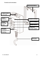
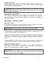
1
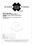
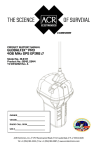
Y1-03-0229C
i
CAUTION: Before proceeding to install, test or use your new
ACR Electronics’ product, please read this Product Support Manual
in its entirety.
If you have questions regarding the contents of the manual, please
contact our Technical Service Department at ACR Electronics, Inc.,
Telephone +1 (954) 981-3333. Please be ready to provide the
technician with the page number you wish to discuss. If you have a
question that is not covered in the manual, please visit our website
and access the Frequently Asked Questions (FAQs) section for
further information or call our Technical Service Department. The
website address is www.acrelectronics.com. If in the future you
lose this manual, you may access and print a replacement on the
ACR website.
Y1-03-0229C
1
Table of Contents
SECTION 1 - HOW THE ARX-50 WORKS _________________________ 2
SECTION 2 - PREPARING TO INSTALL ___________________________ 3
SECTION 3 - INSTALLATION ___________________________________ 5
SECTION 4 - OPERATION _____________________________________ 6
SECTION 5 - MAINTENANCE __________________________________ 9
APPENDIX A - SPECIFICATIONS ________________________________ 9
APPENDIX B - ACCESSORIES __________________________________ 10
APPENDIX C - WARRANTY, USEFUL LIFE POLICY, NOTICES __________ 10
PLEASE READ ALL WARNINGS, CAUTIONS
AND NOTES CAREFULLY
Y1-03-0229C
2
SECTION 1 - HOW THE ARX-50 WORKS
The ARX-50 alarm receiver is designed as a companion to the ACR radio
beacon transmitter model number RBL-30 (Mini B™300). It is intended to be
used in a crew overboard (COB) alerting application.
When properly powered and fitted with an external antenna, the signals
from the Mini B™300 transmitter can be received by the ARX-50 up to
several miles. While the ARX-50 may receive signals from other radio
beacons, it is optimized for service with the ACR Mini B™300 personal
beacon. The ARX-50 is designed to accept ship’s power supply in the
range of +10.5 to +28 V DC.
SECTION 2 - PREPARING TO INSTALL
Unpacking the ARX-50
Before proceeding with the installation of the ARX-50, please verify that the
content of the box includes the following:
Quantity
1
1
1
4
1
1
1
Item
ARX-50 Alarm Receiver with attached I/O cable (1m)
ARX-50 mounting bracket
Monopole antenna
Stainless steel #8 X 1” Phillips screws
Warranty card
Registration card
ARX-50 Product Support Manual
If you do not have all of the items, please call ACR Technical Support at
+1(954) 981-3333.
Y1-03-0229C
3
Controls and indicators
Mounting bracket
Coaxial (BNC)
connector
Alarm
indicator
Signal
strength
meter
Weather
resistant
polycarbonate
housing
Speaker location
On/Off switch
Mode switch
Frequency
selector switch
I/O cable
Y1-03-0229C
4
Location selection
Choose a dry, clean surface to install the ARX-50, giving consideration to
the importance of the location. The user must be able to see the visual
alarm and hear the audible alarm.
CAUTION: When using the included antenna, the ARX-50 must be
mounted vertically and the antenna must not be within 0.5 m of a metal
panel or other metal objects.
Ship’s power requirements
The ARX-50 accepts ship’s power supply in the range of +10.5 to +28 V
DC. A two-wire connection (ground negative) is required that is capable of
supplying 120 mA average and up to 400 mA under an alarm condition at
+10.5 to +28 V DC.
SECTION 3 - INSTALLATION
Mount the bracket
After selecting the location, hold the ARX-50 bracket in position and use as
a template to mark where the screws will be located.
CAUTION: When mounting to a wall, avoid mounting to metal.
Pre-drill holes of a smaller diameter than the screws, if appropriate for the
material that the bracket will be attached to.
Holding the bracket in place, screw the four supplied screws through the
openings in the bracket to the mounting material, securing the screws
tightly enough to allow for vibration, yet loose enough to avoid cracking the
case.
Snap the ARX-50 into its bracket vertically, antenna skyward. Double-check
that the ARX-50 is seated and secure by manually testing it for stability.
Install the monopole antenna
Install the monopole antenna on the ARX-50 via the BNC connector. The
open end of the antenna is attached to the connector by a clockwise
motion. The antenna snaps into place, locking it.
CAUTION: Proper installation of the monopole antenna is required to
seal the ARX-50. If any antenna other than the included monopole antenna
is used, the unit may not seal properly.
Y1-03-0229C
5
Connect the power supply
The ship’s power supply is the source of power for the ARX-50. A onemeter I/O cable is supplied with the product.
It is recommended that a qualified marine electronics professional or
qualified electrician connect the power.
Wiring
The 1m I/O cable wiring chart is as follows:
Signal
Positive power (12 to 24V nominal)
Ground
SpeakerSpeaker+
Relay- common
Relay- normally open
Wire Color
Red
Black
Brown
Orange
Yellow
Green
Installation options
The ARX-50 is designed to be flexible, allowing for user preferences. For
this reason, the system provides relay contacts for a variety of connections.
The relay contacts output in the ARX-50 is a floating metallic switch that
closes upon alarm receipt. It is capable of switching a circuit carrying up to
two amps, at up to 30 volts. The contacts, which are normally open, can be
used for a variety of purposes, including:
Sending input to an external GPS to save position
Switching to an external siren or bell for an alarm
An external speaker may also be connected using the speaker wires on the
I/O cable.
NOTE: It is recommended that a qualified marine electronics professional
or qualified electrician connect such optional devices. While ACR allows
customized connections to the ARX-50, non-standard configurations are
not supported by ACR due to the number of unknowns and variables
involved.
SECTION 4 - OPERATION
Operation overview
The ARX-50 is a 121.5 MHz radio beacon receiver that is part of a ship’s
crew overboard (COB) system. To properly protect officers, crew and
passengers from COB, each individual will need to wear or carry on their
person a locator beacon such as an ACR Mini B™300 series beacon. If the
beacon is activated in a COB situation, the ARX-50 receiver will detect the
121.5 MHz signal. Audible and visual alarms will be triggered.
Y1-03-0229C
6
The ARX-50 has three large, circular push buttons and seven LEDs that
indicate settings. The push buttons switch between alternate modes. Each
button is assigned a set of functions. See Figure 1. Each button “beeps”
when depressed. The LED indicators are either red or green to signify the
system mode. Green LEDs signify that the system is in a normal state and
red LEDs signify that the system is in an atypical state.
Turn on the ARX-50
The red OFF LED will be illuminated while the system is turned off, yet is
still connected to a power supply. To turn on the ARX-50, depress the
On/Off button. The LEDs will blink on and off, and the green On LED will
illuminate. Set to default at the factory, the alarm mode is active on channel
121.5 MHz. Some signal level indicators may flicker while the unit searches
for a signal.
Choose Alarm mode or Monitor mode
Alarm mode
The Alarm mode for the ARX-50 is the system’s default mode. In this mode,
the radio beacon signal detector circuitry is activated, i.e., The system is
ready to detect 121.5 MHz signals.
In Alarm mode, the speaker is silenced until a 121.5 MHz beacon signal is
detected, at which time a loud audible siren and a flashing bright red LED
are activated.
The ARX-50 detects an activated Mini B™300 beacon, and other activated
beacons that transmit 121.5 MHz signals.
The ARX-50 is designed to only detect an alarm on 121.5 MHz signals that
originate from an activated beacon.
The signal strength meter is always active in this mode. If there is a strong
signal that is not from a beacon, the signal strength will still be displayed on
the signal strength meter, but the ARX-50 will not alarm.
Monitor High mode
This mode is intended for advanced users to obtain more information about
a received signal.
NOTE: The ARX-50 reverts back to Alarm mode after 15 minutes in
Monitor High mode.
In the monitor modes, the ARX-50 detector circuitry is deactivated. The
demodulated 121.5 MHz audio signal is annunciated at all times. If there is
not any signal on the 121.5 MHz carrier, whether activated beacon or other
source, static will be audible. The speaker volume is high, and the signal
strength meter is active.
Y1-03-0229C
7
Monitor Low mode
This mode is identical to the Monitor High mode except that the speaker
volume is lower.
NOTE: The ARX-50 reverts back to Alarm mode after 15 minutes in
Monitor High mode.
Training mode
Operation in Training mode is identical to the live radio beacon detection
mode.
In Training mode, the ARX-50 receives a special training frequency
(typically 121.65 MHz or 121.775 MHz). This allows users to become
familiar with the operation of the ARX-50 by using a special training beacon
operating on the same frequency. This way, local Search and Rescue
authorities are not notified.
NOTE: The ARX-50 reverts back to 121.5 MHz after 1 hour in Training
mode.
Activation and alarm indicators
The ARX-50 is a fully automatic monitor/receiver. In Alarm mode, once the
ARX-50 detects a signal, a loud audible alarm will sound and a bright red
LED will flash.
Signal strength meter
The eight LEDs on the signal strength meter are capable of indicating
sixteen levels of received signal strength.
The signal strength meter provides the user with an indication of how far
away the 121.5 MHz signal might be. The higher the LEDs are illuminated,
the stronger the 121.5 MHz transmitted signal is, and the closer the signal
is relative to the ARX-50.
The reverse is also true: The lower the lit LEDs are, the less signal
strength, and the further away the beacon is relative to the ARX-50.
NOTE: The signal strength meter may display a low level of activity any
time that the ARX-50 is on. This is not to be mistaken for detection of a
121.5 MHz beacon transmission.
Y1-03-0229C
8
SECTION 5 - MAINTENANCE
The following maintenance schedule is recommended:
Action
Visual inspection
Performance
test
Clean exterior
Description
Frequency
Inspect the antenna, cables and
connections. Ensure that the cable is
attached properly and the unit has not been
damaged.
Every 6 months
Verify that the system is operating by
using the training mode with a training
beacon
Using a mild, sudsy solution such as
dishwashing liquid, wipe the surface of
the ARX-50 with a damp cloth to
remove film, salt and sand
Every year
As needed
APPENDIX A - SPECIFICATIONS
General
Carrier frequency
Sensitivity
VHF antenna
Modulation
Electrical input power
121.5 MHz or 121.65 MHz, user selectable
<0.2 µV (at antenna output)
Flexible monopole
Swept tone
+10.5 V to +28 V DC, 120 mA average, 400 mA
maximum
Alert methods
Bright red flashing led
Loud audible alarm (≈70dBA @ 1m)
External speaker connection (8v maximum)
Relay contacts: normally open (2 A/30 V
maximum)
Regulation conformity
Safety
EMI/EMC
RoHS/WEEE
Physical
Dimensions
Weather resistance
Operating temperature
Storage temperature
Weight
Y1-03-0229C
IEC 60945, EN50371
IEC 60945
European Directive 2002/95/EC
5.3” X 3.7” X 1.5” (13.46 X 9.40 X 3.81cm)
IP65 (when included monopole antenna is
correctly installed)
-4°F to +131°F(-20°C to +55°C)
-40°F to +158°F (-40°C TO +70°C)
0.8 lbs (362.87 g)
9
APPENDIX B - ACCESSORIES
The following are items that can be ordered for your alarm receiver:
Description
Mini B™300 ILS H2ON (water activated)
Mini B™300 ILS (manually activated)
ACR Part Number
2767
2766.6
APPENDIX C - WARRANTY, USEFUL LIFE POLICY,
NOTICES
Limited Warranty
This product is warranted against factory defects in material and
workmanship for a period of 1 (one) year* from date of purchase or receipt
as a gift. During the warranty period ACR Electronics, Inc. will repair or, at
its option, replace the unit at no cost to you for labor, materials and return
transportation from ACR. For further assistance, please contact our
Technical Service Department at ACR Electronics, Inc., 5757 Ravenswood
Road, Fort Lauderdale, FL 33312-6645. Telephone: +1 (954) 981-3333,
Fax: +1 (954) 983-5087, Email: [email protected].
This warranty does not apply if the product has been damaged by accident
or misuse, or as a result of service or modification performed by an
unauthorized factory. Except as otherwise expressly stated in the previous
paragraph, THE COMPANY MAKES NO REPRESENTATION OR
WARRANTY OF ANY KIND, EXPRESS OR IMPLIED, AS TO
MERCHANTABILITY, FITNESS FOR A PARTICULAR PURPOSE, OR
ANY OTHER MATTER WITH RESPECT TO THIS PRODUCT. The
Company shall not be liable for consequential or special damages.
To place the warranty in effect, register online at www.acrelectronics.com
or return the attached card within 10 days.
*Five years for the following products: EPIRB, PLB, S-VDR, SSAS.
Useful Life Policy
The typical service life of a properly maintained Product is limited to 12
years from date of manufacture. Products that are 12 years and 1 month or
older from date of manufacture will not be serviced by ACR or our Battery
Replacement Centers. A Product that is 12 or less years old from date of
manufacture will be serviced as long as the unit appears fit to be placed
back into its final operational cycle. Service includes the replacement of
those items that must be replaced at service intervals and the verification
that the device appears to be in good mechanical and electrical working
condition by an ACR authorized service technician.
Y1-03-0229C
10
FCC Compliance Statement
NOTE: This equipment has been tested and found to comply with the limits
for a Class B digital device, pursuant to part 15 of the FCC Rules. These
limits are designed to provide reasonable protection against harmful
interference in a residential installation. This equipment generates, uses nd
can radiate radio frequency energy and, if not installed and used in
accordance with the instructions, may cause harmful interference to radio
communications. However, there is no guarantee that interference will not
occur in a particular installation. If this equipment does cause harmful
interference to radio or television reception, which can be determined by
turning the equipment off and on, the user is encouraged to try to correct
the interference by one or more of the following measures:
Reorient or relocate the receiving antenna.
Increase the separation between the equipment and receiver.
Connect the equipment into an outlet on a circuit different from that to
which the receiver is connected.
Consult the dealer or an experienced radio/TV technician for help.
Notices
ACR Electronics diligently works to provide a high quality Product Support
Manual, however, despite best efforts, information is subject to change
without notice, and omissions and inaccuracies are possible. ACR cannot
accept liability for manual contents. To ensure that you have the most
recent version of the Product Support Manual, please visit the ACR website
at www.acrelectronics.com.
©2008 by ACR Electronics, Inc., part of Cobham plc. All rights reserved.
Reproduction in whole or in part is permitted only with permission of ACR
Electronics, Inc. Ongoing product improvements may change product
specifications without notice.
Trademarks or registered trademarks are the property of their respective
owners.
Y1-03-0229C
11
EC DECLARATION OF CONFORMITY
ACR Electronics, Inc. hereby declares that the following product is in conformity with Directive
1999/5/EC of the European Parliament and of the Council of 9 March 1999 on Radio
Equipment and Telecommunications Terminal Equipment (R&TTE). In accordance with the
Directive, the product will be marked with the CE conformity marking as follows:
Product:
Man Overboard Alarm Receiver
Model: ARX-50
Regulations and
Standards:
IEC 60945: 2002
BS EN 50371: 2002
Manufacturer:
ACR Electronics, Inc.
5757 Ravenswood Road
Fort Lauderdale, FL 33312 USA
European
Representative:
ACR Electronics, Inc.
(European Office)
1 Rose Cottages, Pitmore Lane,
Sway, Lymington, Hampshire
SO41 6BX, United Kingdom
Signed on behalf of ACR Electronics Inc.
Signed: _______________________________________
Name:
Kerry Greer
Title:
VP Engineering
Date:
January 9, 2009
Document ARX-50-001
This Declaration complies with ISO/IEC 17050-1:2004
ACR Electronics, Inc. is registered by UL to ISO 9001:2000
Y1-03-0229C
12