1
Installation Guide
ECL Comfort 310, application A361
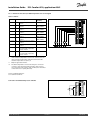
1.0 Table of Contents
1.0 Table of Contents ............................................... 1
6.0 Settings, circuit 2 ............................................. 75
1.1
6.1
6.2
6.3
6.4
6.5
6.6
6.7
6.8
6.9
Important safety and product information. . . . . . . . . . . . . . . . . . . . . 2
2.0 Installation ........................................................ 4
2.1
2.2
2.3
2.4
2.5
2.6
2.7
2.8
Before you start . . . . . . . . . . . . . . . . . . . . . . . . . . . . . . . . . . . . . . . . . . . . . . . . . . . . . 4
Identifying the system type . . . . . . . . . . . . . . . . . . . . . . . . . . . . . . . . . . . . . . . 8
Mounting . . . . . . . . . . . . . . . . . . . . . . . . . . . . . . . . . . . . . . . . . . . . . . . . . . . . . . . . . . . 10
Placing the temperature sensors. . . . . . . . . . . . . . . . . . . . . . . . . . . . . . . . 13
Electrical connections. . . . . . . . . . . . . . . . . . . . . . . . . . . . . . . . . . . . . . . . . . . . . 15
Inserting the ECL Application Key . . . . . . . . . . . . . . . . . . . . . . . . . . . . . . 25
Check list . . . . . . . . . . . . . . . . . . . . . . . . . . . . . . . . . . . . . . . . . . . . . . . . . . . . . . . . . . . . 30
Navigation, ECL Application Key A361 . . . . . . . . . . . . . . . . . . . . . . . . . 31
3.0 Daily use ......................................................... 34
3.1
3.2
3.3
3.4
3.5
3.6
How to navigate . . . . . . . . . . . . . . . . . . . . . . . . . . . . . . . . . . . . . . . . . . . . . . . . . . . 34
Understanding the controller display . . . . . . . . . . . . . . . . . . . . . . . . . . 35
What do the symbols mean?. . . . . . . . . . . . . . . . . . . . . . . . . . . . . . . . . . . . . 37
Monitoring temperatures and system
components . . . . . . . . . . . . . . . . . . . . . . . . . . . . . . . . . . . . . . . . . . . . . . . . . . . . . . . . 38
Manual control . . . . . . . . . . . . . . . . . . . . . . . . . . . . . . . . . . . . . . . . . . . . . . . . . . . . . 39
Schedule . . . . . . . . . . . . . . . . . . . . . . . . . . . . . . . . . . . . . . . . . . . . . . . . . . . . . . . . . . . . 40
Flow temperature. . . . . . . . . . . . . . . . . . . . . . . . . . . . . . . . . . . . . . . . . . . . . . . . . . 75
Return limit . . . . . . . . . . . . . . . . . . . . . . . . . . . . . . . . . . . . . . . . . . . . . . . . . . . . . . . . . 80
Flow / power limit . . . . . . . . . . . . . . . . . . . . . . . . . . . . . . . . . . . . . . . . . . . . . . . . . 83
Optimization. . . . . . . . . . . . . . . . . . . . . . . . . . . . . . . . . . . . . . . . . . . . . . . . . . . . . . . . 86
Control parameters. . . . . . . . . . . . . . . . . . . . . . . . . . . . . . . . . . . . . . . . . . . . . . . . 90
Pump control . . . . . . . . . . . . . . . . . . . . . . . . . . . . . . . . . . . . . . . . . . . . . . . . . . . . . . . 93
Refill water . . . . . . . . . . . . . . . . . . . . . . . . . . . . . . . . . . . . . . . . . . . . . . . . . . . . . . . . . . 95
Application . . . . . . . . . . . . . . . . . . . . . . . . . . . . . . . . . . . . . . . . . . . . . . . . . . . . . . . . . 99
Alarm . . . . . . . . . . . . . . . . . . . . . . . . . . . . . . . . . . . . . . . . . . . . . . . . . . . . . . . . . . . . . . 102
7.0 Common controller settings............................ 105
7.1
7.2
7.3
7.4
7.5
7.6
7.7
7.8
Introduction to ‘Common controller settings’ . . . . . . . . . . . . . .
Time & Date. . . . . . . . . . . . . . . . . . . . . . . . . . . . . . . . . . . . . . . . . . . . . . . . . . . . . . .
Holiday . . . . . . . . . . . . . . . . . . . . . . . . . . . . . . . . . . . . . . . . . . . . . . . . . . . . . . . . . . . .
Input overview . . . . . . . . . . . . . . . . . . . . . . . . . . . . . . . . . . . . . . . . . . . . . . . . . . .
Log . . . . . . . . . . . . . . . . . . . . . . . . . . . . . . . . . . . . . . . . . . . . . . . . . . . . . . . . . . . . . . . . .
Output override. . . . . . . . . . . . . . . . . . . . . . . . . . . . . . . . . . . . . . . . . . . . . . . . . .
Key functions . . . . . . . . . . . . . . . . . . . . . . . . . . . . . . . . . . . . . . . . . . . . . . . . . . . . .
System . . . . . . . . . . . . . . . . . . . . . . . . . . . . . . . . . . . . . . . . . . . . . . . . . . . . . . . . . . . . .
105
106
107
109
110
111
112
113
8.0 Miscellaneous ................................................ 115
4.0 Settings overview ............................................ 41
8.1
8.2
Frequently asked questions. . . . . . . . . . . . . . . . . . . . . . . . . . . . . . . . . . . . 115
Definitions . . . . . . . . . . . . . . . . . . . . . . . . . . . . . . . . . . . . . . . . . . . . . . . . . . . . . . . . 117
5.0 Settings, circuit 1 ............................................. 45
5.1
5.2
5.3
5.4
5.5
5.6
5.7
5.8
5.9
Flow temperature. . . . . . . . . . . . . . . . . . . . . . . . . . . . . . . . . . . . . . . . . . . . . . . . . . 45
Return limit . . . . . . . . . . . . . . . . . . . . . . . . . . . . . . . . . . . . . . . . . . . . . . . . . . . . . . . . . 50
Flow / power limit . . . . . . . . . . . . . . . . . . . . . . . . . . . . . . . . . . . . . . . . . . . . . . . . . 53
Optimization. . . . . . . . . . . . . . . . . . . . . . . . . . . . . . . . . . . . . . . . . . . . . . . . . . . . . . . . 56
Control parameters. . . . . . . . . . . . . . . . . . . . . . . . . . . . . . . . . . . . . . . . . . . . . . . . 60
Pump control . . . . . . . . . . . . . . . . . . . . . . . . . . . . . . . . . . . . . . . . . . . . . . . . . . . . . . . 62
Refill water . . . . . . . . . . . . . . . . . . . . . . . . . . . . . . . . . . . . . . . . . . . . . . . . . . . . . . . . . . 64
Application . . . . . . . . . . . . . . . . . . . . . . . . . . . . . . . . . . . . . . . . . . . . . . . . . . . . . . . . . 68
Alarm . . . . . . . . . . . . . . . . . . . . . . . . . . . . . . . . . . . . . . . . . . . . . . . . . . . . . . . . . . . . . . . . 72
Danfoss District Energy
VI.LG.M1.02
DEN-SMT/DK
1
Installation Guide
ECL Comfort 310, application A361
1.1 Important safety and product information
1.1.1 Important safety and product information
This Installation Guide is associated with ECL Application Key A361
(order code no. 087H3804).
The functions can be realized with ECL Comfort 310.
The application A361 complies with ECL Comfort controller 310 as
of software version 1.10 (visible at start-up of the controller and in
‘Common controller settings’ in ‘System’).
Additional documentation for ECL Comfort 210 and 310, modules
and accessories is available on http://den.danfoss.com/.
Safety Note
To avoid injury of persons and damages to the device, it is absolutely
necessary to read and observe these instructions carefully.
Necessary assembly, start-up, and maintenance work must be
performed by qualified and authorized personnel only.
The warning sign is used to emphasize special conditions that should
be taken into consideration.
This symbol indicates that this particular piece of information should
be read with special attention.
As this Installation Guide covers several system types, special system
settings will be marked with a system type. All system types are shown
in the chapter: 'Identifying your system type'.
°C (degrees Celsius) is a measured temperature value whereas K
(Kelvin) is a number of degrees.
2
DEN-SMT/DK
VI.LG.M1.02
Danfoss District Energy
Installation Guide
ECL Comfort 310, application A361
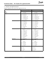
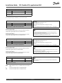
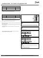
The ID no. is unique for the selected parameter.
Example
First digit
Second digit
Last three digits
11174
1
1
174
-
Circuit 1
Parameter no.
1
2
174
-
Circuit 2
Parameter no.
12174
If an ID description is mentioned more than once, it means that there
are special settings for one or more system types. It will be marked
with the system type in question (e.g. 12174 - A266.9).
Disposal Note
This product should be dismantled and its components
sorted, if possible, in various groups before recycling
or disposal.
Always follow the local disposal regulations.
Danfoss District Energy
VI.LG.M1.02
DEN-SMT/DK
3
Installation Guide
ECL Comfort 310, application A361
2.0 Installation
2.1 Before you start
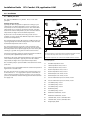
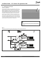
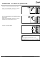
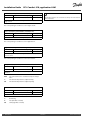
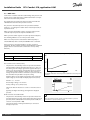
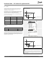
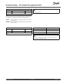
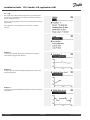
The application A361.1 is very flexible. These are the basic
principles:
Typical A361.1 application:
Da nfos s
87H2002.10
ECL 310
S1
Heating (circuit 1 and 2):
Typically, the flow temperature is adjusted according to your
requirements. The flow temperature sensor S3 (circuit 1) and
S4 (circuit 2) are the most important sensors. The desired flow
temperatures at S3 and S4 are calculated in the ECL controller,
based on the outdoor temperature (S1). The lower the outdoor
temperature, the higher the desired flow temperature.
R6
P S7
S3
P1
P2
M1
By means of a week schedule, the heating circuit can be in
‘Comfort’ or ‘Saving’ mode (two different temperature values for
desired room temperature).
S5
S10
V1
P4
P S8
S4
P3
P5
The motorized control valves M1 (circuit 1) and M2 (circuit 2) are
opened gradually when the flow temperature is lower than the
desired flow temperature and vice versa.
M2
S6
S9
V2
The return temperatures S5 (circuit 1) and S6 (circuit 2) to the
district heating supply should not be too high. If so, the desired
flow temperature can be adjusted (typically to a lower value), thus
resulting in a gradual closing of the motorized control valves.
In boiler-based heating supply the return temperature should not
be too low (same adjustment procedure as above).
The shown diagram is a fundamental and simplified example and does
not contain all components that are necessary in a system.
Furthermore, the return temperature limitation can be dependent
of the outdoor temperature. Typically, the lower the outdoor
temperature, the higher the accepted return temperature.
All named components are connected to the ECL Comfort controller.
The circulation pump in question is ON at heat demand or at frost
protection.
S1
S3
Flow temperature sensor, circuit 1
The heating can be switched OFF when the outdoor temperature is
higher than a selectable value.
S4
Flow temperature sensor, circuit 2
S5
Return temperature sensor, circuit 1
The static pressure on the secondary side (consumer side) can 1)
be measured as a 0 - 10 V signal (from a pressure transmitter) or
2) be a switch signal from a pressure switch. In case of a too low
pressure, the refill water function will supplement with water from
the supply side.
4
List of components:
DEN-SMT/DK
Outdoor temperature sensor
S6
Return temperature sensor, circuit 2
S7
Differential pressure switch, circuit 1
S8
Differential pressure switch, circuit 2
S9
Pressure transmitter or pressure switch, circuit 2
S10
Pressure transmitter or pressure switch, circuit 1
P1
Circulation pump, circuit 1
P2
Circulation pump, circuit 1
P3
Circulation pump, circuit 2
P4
Refill water pump
P5
Circulation pump, circuit 2
M1
Motorized control valve, circuit 1
M2
Motorized control valve, circuit 2
V1
Solenoid valve, circuit 1, refill water valve
V2
Solenoid valve, circuit 2, refill water valve
R6
Relay output, alarm
VI.LG.M1.02
Danfoss District Energy
ECL Comfort 310, application A361
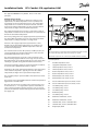
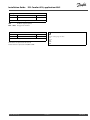
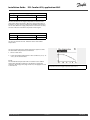
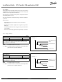
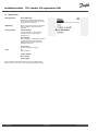
Application A361.1 in general:
Typical A361.1 application:
The circulation pumps P1 and P2 (circuit 1) / P3 and P5 ( circuit 2)
work in shift according to a schedule. One pump is used as spare
pump and the other pump is working. In case of malfunction
(missing differential pressure) of one pump, the other pump will
take over. An alarm will be generated and the defective pump can
be inspected / repaired.
ECL 310
S1
Da nfos s
87H2002.10
Installation Guide
R6
P S7
S3
P1
P2
Alarm (relay 6) can be activated if:
M1
•
The actual flow temperature differs from the desired flow
temperature.
S5
V1
P4
•
The activated circulation pump does not generate a pressure
difference.
•
The refill water function does not generate a pressure within
a preset time.
S10
P S8
S4
P3
P5
M2
S6
S9
V2
Modbus communication to a SCADA system can be established.
M-bus communication enables connection to flow or energy meter.
The controller can limit the flow or energy to a set maximum but
also in relation to the outdoor temperature.
Furthermore, the M-bus data can be transferred to the Modbus
communication.
Danfoss District Energy
VI.LG.M1.02
DEN-SMT/DK
5
Installation Guide
ECL Comfort 310, application A361
The application A361.2 is very flexible. These are the basic
principles:
Typical A361.2 application:
Heating (circuit 1 and 2):
Typically, the flow temperature is adjusted according to your
requirements. The flow temperature sensor S3 (circuit 1) and
S4 (circuit 2) are the most important sensors. The desired flow
temperatures at S3 and S4 are calculated in the ECL controller,
based on the outdoor temperature (S1). The lower the outdoor
temperature, the higher the desired flow temperature.
The supply temperature (S2) is used to 1) control the S3 and S4
temperatures in relation to the S2 temperature or 2) maximize the
limit of the desired flow temperature.
The factory setting, where the supply temperature (S2) determines
the desired flow temperature, does not change the desired flow
temperature according to ‘Comfort’ or ‘Saving’ mode.
However, if the supply temperature (S2) determines a max.
limitation of the desired flow temperature, the ‘Comfort’ and
‘Saving’ mode will have two different temperature values for
desired room temperature.
The motorized control valves M1 (circuit 1) and M2 (circuit 2) are
opened gradually when the flow temperature is lower than the
desired flow temperature and vice versa.
The return temperatures S5 (circuit 1) and S6 (circuit 2) to the
district heating supply should not be too high. If so, the desired
flow temperature can be adjusted (typically to a lower value), thus
resulting in a gradual closing of the motorized control valves.
In boiler-based heating supply the return temperature should not
be too low (same adjustment procedure as above).
Furthermore, the return temperature limitation can be dependent
of the outdoor temperature. Typically, the lower the outdoor
temperature, the higher the accepted return temperature.
The circulation pump in question is ON at heat demand or at frost
protection.
The heating can be switched OFF when the outdoor temperature is
higher than a selectable value.
The static pressure on the secondary side (consumer side) can 1)
be measured as a 0 - 10 V signal (from a pressure transmitter) or
2) be a switch signal from a pressure switch. In case of a too low
pressure, the refill water function will supplement with water from
the supply side.
6
DEN-SMT/DK
The shown diagram is a fundamental and simplified example and does
not contain all components that are necessary in a system.
All named components are connected to the ECL Comfort controller.
List of components:
S1
Outdoor temperature sensor
S2
Supply flow temperature sensor
S3
Flow temperature sensor, circuit 1
S4
Flow temperature sensor, circuit 2
S5
Return temperature sensor, circuit 1
S6
Return temperature sensor, circuit 2
S7
Differential pressure switch, circuit 1
S8
Differential pressure switch, circuit 2
S9
Pressure transmitter or pressure switch, circuit 2
S10
Pressure transmitter or pressure switch, circuit 1
P1
Circulation pump, circuit 1
P2
Circulation pump, circuit 1
P3
Circulation pump, circuit 2
P4
Refill water pump
P5
Circulation pump, circuit 2
M1
Motorized control valve, circuit 1
M2
Motorized control valve, circuit 2
V1
Solenoid valve, circuit 1, refill water valve
V2
Solenoid valve, circuit 2, refill water valve
R6
Relay output, alarm
VI.LG.M1.02
Danfoss District Energy
Installation Guide
ECL Comfort 310, application A361
Application A361.2 in general:
Typical A361.2 application:
The circulation pumps P1 and P2 ( circuit 1) / P3 and P5 ( circuit 2)
work in shift according to a schedule. One pump is used as spare
pump and the other pump is working. In case of malfunction
(missing differential pressure) of one pump, the other pump will
take over. An alarm will be generated and the defective pump can
be inspected / repaired.
Alarm (relay 6) can be activated if:
•
The actual flow temperature differs from the desired flow
temperature.
•
The activated circulation pump does not generate a pressure
difference.
•
The refill water function does not generate a pressure within
a preset time.
Modbus communication to a SCADA system can be established.
M-bus communication enables connection to flow or energy meter.
The controller can limit the flow or energy to a set maximum but
also in relation to the outdoor temperature.
Furthermore, the M-bus data can be transferred to the Modbus
communication.
The controller is pre-programmed with factory settings that are shown
in the relevant chapters of this guide.
Danfoss District Energy
VI.LG.M1.02
DEN-SMT/DK
7
Installation Guide
ECL Comfort 310, application A361
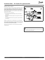
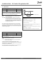
2.2 Identifying the system type
Sketch your application
The ECL Comfort controller series is designed for a wide range
of heating, domestic hot-water (DHW) and cooling systems with
different configurations and capacities. If your system differs
from the diagrams shown here, you may want to make a sketch
of the system about to be installed. This makes it easier to use
the Installation Guide, which will guide you step-by-step from
installation to final adjustments before the end-user takes over.
The ECL Comfort controller is a universal controller that can be
used for various systems. Based on the shown standard systems,
it is possible to configure additional systems. In this chapter you
find the most frequently used systems. If your system is not quite
as shown below, find the diagram which has the best resemblance
with your system and make your own combinations.
The circulation pump(s) in heating circuit(s) can be placed in the flow
as well as the return. Place the pump according to the manufacturer’s
specification.
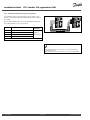
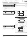
A361.1
Indirectly connected heating systems with two-pump control and refill water function:
Da nfos s
87H2002.10
ECL 310
S1
R6
P S7
S3
P1
P2
M1
S5
S10
V1
P4
P S8
S4
P3
P5
M2
S6
S9
V2
8
DEN-SMT/DK
VI.LG.M1.02
Danfoss District Energy
Installation Guide
ECL Comfort 310, application A361
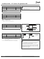
A361.2
Indirectly connected heating systems with two-pump control and refill water function (supply temperature measurement gives further
control / limitation possibilities):
Danfoss District Energy
VI.LG.M1.02
DEN-SMT/DK
9
Installation Guide
ECL Comfort 310, application A361
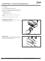
2.3 Mounting
2.3.1 Mounting the ECL Comfort controller
For easy access, you should mount the ECL Comfort controller near
the system. Select one of the following methods using the same
base part (code no. 087H3220):
•
Mounting on a wall
•
Mounting on a DIN rail (35 mm)
The ECL Comfort 310 is to be mounted in the ECL Comfort 310
base part.
Screws, PG cable glands and rawlplugs are not supplied.
Locking the ECL Comfort controller
In order to fasten the ECL Comfort controller to its base part, secure
the controller with the locking pin.
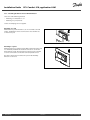
Mounting on a wall
Mount the base part on a wall with a smooth surface. Establish the
electrical connections and position the controller in the base part.
Secure the controller with the locking pin.
10
DEN-SMT/DK
VI.LG.M1.02
Danfoss District Energy
Installation Guide
ECL Comfort 310, application A361
Mounting on a DIN rail (35 mm)
Mount the base part on a DIN rail. Establish the electrical
connections and position the controller in the base part. Secure
the controller with the locking pin.
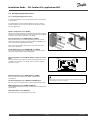
Dismounting the ECL Comfort controller
In order to remove the controller from the base part, pull out the
locking pin by means of a screwdriver. The controller can now be
removed from the base part.
Danfoss District Energy
VI.LG.M1.02
DEN-SMT/DK
11
Installation Guide
ECL Comfort 310, application A361
2.3.2 Mounting the Remote Control Units ECA 30/31
Select one of the following methods:
•
Mounting on a wall, ECA 30 / 31
•
Mounting in a panel, ECA 30
Screws and rawlplugs are not supplied.
Mounting on a wall
Mount the base part of the ECA 30 / 31 on a wall with a smooth
surface. Establish the electrical connections. Place the ECA 30 /
31 in the base part.
Mounting in a panel
Mount the ECA 30 in a panel using the ECA 30 frame kit (order code
no. 087H3236). Establish the electrical connections. Secure the
frame with the clamp. Place the ECA 30 in the base part. The ECA
30 can be connected to an external room temperature sensor.
The ECA 31 must not be mounted in a panel if the humidity
function is to be used.
12
DEN-SMT/DK
VI.LG.M1.02
Danfoss District Energy
Installation Guide
ECL Comfort 310, application A361
2.4 Placing the temperature sensors
2.4.1 Placing the temperature sensors
It is important that the sensors are mounted in the correct position
in your system.
The temperature sensor mentioned below are sensors used for
the ECL Comfort 210 and 310 series which not all will be needed
for your application!
Outdoor temperature sensor (ESMT)
The outdoor sensor should be mounted on that side of the building
where it is less likely to be exposed to direct sunshine. It should not
be placed close to doors, windows or air outlets.
Flow temperature sensor (ESMU, ESM-11 or ESMC)
Place the sensor max. 15 cm from the mixing point. In systems
with heat exchanger, Danfoss recommends that the ESMU-type to
be inserted into the exchanger flow outlet.
Make sure that the surface of the pipe is clean and even where
the sensor is mounted.
Return temperature sensor (ESMU, ESM-11 or ESMC)
The return temperature sensor should always be placed so that it
measures a representative return temperature.
Room temperature sensor (ESM-10, ECA 30 / 31 Remote Control
Unit)
Place the room sensor in the room where the temperature is to be
controlled. Do not place it on outside walls or close to radiators,
windows or doors.
Boiler temperature sensor (ESMU, ESM-11 or ESMC)
Place the sensor according to the boiler manufacturer’s
specification.
Air duct temperature sensor (ESMB-12 or ESMU types)
Place the sensor so that it measures a representative temperature.
ESM-11: Do not move the sensor after it has been fastened in order to
avoid damage to the sensor element.
DHW temperature sensor (ESMU or ESMB-12)
Place the DHW temperature sensor according to the manufacturer’s
specification.
Slab temperature sensor (ESMB-12)
Place the sensor in a protection tube in the slab.
Danfoss District Energy
VI.LG.M1.02
DEN-SMT/DK
13
Installation Guide
ECL Comfort 310, application A361
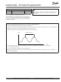
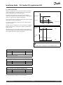
Pt 1000 temperature sensor (IEC 751B, 1000 Ω / 0 °C)
Relationship between temperature and ohmic value:
Ω
°C
Ω
-50
-40
-30
-20
-10
0
10
20
30
40
50
60
70
80
90
100
110
120
130
140
150
803
843
882
922
961
1000
1039
1078
1117
1155
1194
1232
1271
1309
1347
1385
1423
1461
1498
1535
1573
1600
1500
1400
1300
1200
1100
1000
900
800
°C
-50
14
DEN-SMT/DK
VI.LG.M1.02
-25
0
25
50
75
100
125
150
Danfoss District Energy
Installation Guide
ECL Comfort 310, application A361
2.5 Electrical connections
2.5.1 Electrical connections 230 V a.c. in general
The common ground terminal is used for connection of relevant
components (pumps, motorized control valves).
Danfoss District Energy
VI.LG.M1.02
DEN-SMT/DK
15
Installation Guide
ECL Comfort 310, application A361
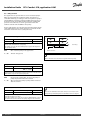
2.5.2 Electrical connections, 230 V a.c., power supply, pumps, motorized control valves etc.
Application A361.1 / A361.2
Terminal
Description
19
Phase for circulation pump and alarm
18
Alarm
4 (2) A / 230 V a.c.*
Circulation pump ON / OFF, circuit 2
4 (2) A / 230 V a.c.*
17
P5
16
15
Max. load
Phase for circulation pump
P4
14
4 (2) A / 230 V a.c.*
Refill water pump ON / OFF
Phase for circulation pumps
13
P3
Circulation pump ON / OFF, circuit 2
4 (2) A / 230 V a.c.*
12
P2
Circulation pump ON / OFF, circuit 1
4 (2) A / 230 V a.c.*
11
P1
Circulation pump ON / OFF, circuit 1
4 (2) A / 230 V a.c.*
10
Supply voltage 230 V a.c. - neutral (N)
9
Supply voltage 230 V a.c. - live (L)
8
M1
Phase for motorized control valve output, circuit 1
7
M1
Actuator - opening
0.2 A / 230 V a.c.
6
M1
Actuator - closing
0.2 A / 230 V a.c.
5
M2
Phase for motorized control valve output, circuit 2
4
M2
Actuator - opening
0.2 A / 230 V a.c.
3
M2
Actuator - closing
0.2 A / 230 V a.c.
2
V1
Solenoid valve, circuit 1, refill water function
0.2 A / 230 V a.c.
1
V2
Solenoid valve, circuit 2, refill water function
0.2 A / 230 V a.c.
* Relay contacts: 4 A for ohmic load, 2 A for inductive load
Factory established jumpers:
5 to 8, 9 to 14, 14 to 16, 16 to 19, L to 5 and L to 9, N to 10
16
DEN-SMT/DK
VI.LG.M1.02
Danfoss District Energy
Installation Guide
ECL Comfort 310, application A361
Wire cross section: 0.5 - 1.5 mm²
Incorrect connection can damage the electronic outputs.
Max. 2 x 1.5 mm² wires can be inserted into each screw terminal.
Danfoss District Energy
VI.LG.M1.02
DEN-SMT/DK
17
Installation Guide
ECL Comfort 310, application A361
2.5.3 Electrical connections, safety thermostats, 230 V a.c. or 24 V a.c.
With safety thermostat, circuit 1:
With safety thermostat, circuit 2:
Wire cross section: 0.5 - 1.5 mm²
Incorrect connection can damage the electronic outputs.
Max. 2 x 1.5 mm² wires can be inserted into each screw terminal.
18
DEN-SMT/DK
VI.LG.M1.02
Danfoss District Energy
Installation Guide
ECL Comfort 310, application A361
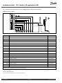
2.5.4 Electrical connections, 24 V a.c., power supply, pumps, motorized valves etc.
Application A361.1 / A361.2
ECL 310/24 V a .c.
R5
R4
R3
R2
R1
N
L
Tr1
Tr2
Tr3
Tr4
Tr5
Tr6
19
18
17
16
15
14
13
12
11
10
9
8
7
6
5
4
3
2
1
N
L
Da nfos s
87H2008.10
R6
M
K7
K6
M2
M
M1
L
K1
K2
K3
K4
K5
N
N
24 V a .c.
N
L
V2
V1
P1
P2
P3
P4
P5
230 V a .c.
N
Terminal
Description
19
Phase for circulation pump and alarm
18
Alarm
4 (2) A / 24 V a.c.*
Circulation pump ON / OFF, circuit 2
4 (2) A / 24 V a.c.*
17
K5
16
15
Max. load
Phase for circulation pump
K4
14
4 (2) A / 24 V a.c.*
Refill water pump ON / OFF
Phase for circulation pumps
13
K3
Circulation pump ON / OFF, circuit 2
4 (2) A / 24 V a.c.*
12
K2
Circulation pump ON / OFF, circuit 1
4 (2) A / 24 V a.c.*
11
K1
Circulation pump ON / OFF, circuit 1
4 (2) A / 24 V a.c.*
10
Supply voltage 24 V a.c. - neutral (N)
9
Supply voltage 24 V a.c. - live (L)
8
M1
Phase for motorized control valve output, circuit 1
7
M1
Actuator - opening
1 A / 24 V a.c.
6
M1
Actuator - closing
1 A / 24 V a.c.
5
M2
Phase for motorized control valve output, circuit 2
4
M2
Actuator - opening
1 A / 24 V a.c.
3
M2
Actuator - closing
1 A / 24 V a.c.
2
K6
Solenoid valve, V1, circuit 1, refill water function
1 A / 24 V a.c.
1
K7
Solenoid valve, V2, circuit 2, refill water function
1 A / 24 V a.c.
* Relay contacts: 4 A for ohmic load, 2 A for inductive load
Factory established jumpers:
5 to 8, 9 to 14, 14 to 16, 16 to 19, L to 5 and L to 9, N to 10
Danfoss District Energy
VI.LG.M1.02
DEN-SMT/DK
19
Installation Guide
ECL Comfort 310, application A361
Wire cross section: 0.5 - 1.5 mm²
Incorrect connection can damage the electronic outputs.
Max. 2 x 1.5 mm² wires can be inserted into each screw terminal.
Do not connect 230 V a.c. powered components to a 24 V a.c. power
supplied controller directly. Use auxilliary relays (K) to seperate 230
V a.c. from 24 V a.c.
20
DEN-SMT/DK
VI.LG.M1.02
Danfoss District Energy
Installation Guide
ECL Comfort 310, application A361
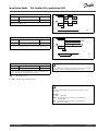
2.5.5 Electrical connections, Pt 1000 temperature sensors and signals
A361.1 / A361.2:
Terminal
Sensor / description
29 and 30 S1
28 and 30
27 and 30
26 and 30
25 and 30
24 and 30
23 and 30
22 and 30
21 and 30
20 and 30
Outdoor temperature
sensor*
S2 Supply flow temperature
sensor**
S3 Flow temperature sensor***,
circuit 1
S4 Flow temperature sensor***,
circuit 2
S5 Return temperature sensor,
circuit 1
S6 Return temperature sensor,
circuit 2
S7 Differential pressure switch,
circuit 1
S8 Differential pressure switch,
circuit 2
S9 Pressure transmitter (0–10
V or 4–20 mA) or pressure
switch, circuit 2
S10 Pressure transmitter (0–10
V or 4–20 mA) or pressure
switch, circuit 1
Type
(recomm.)
ESMT
ESM-11 / ESMB /
ESMC / ESMU
ESM-11 / ESMB /
ESMC / ESMU
ESM-11 / ESMB /
ESMC / ESMU
ESM-11 / ESMB /
ESMC / ESMU
ESM-11 / ESMB /
ESMC / ESMU
*
If the outdoor temperature sensor is not connected or the
cable is short-circuited, the controller assumes that the
outdoor temperature is 0 (zero) °C.
**
Only for application A361.2.
***
The flow temperature sensor must always be connected
in order to have the desired functionality. If the sensor is
not connected or the cable is short-circuited, the motorized
control valve closes (safety function).
Factory established jumper:
30 to common terminal.
Connection of 2 differential pressure switches
Danfoss District Energy
VI.LG.M1.02
DEN-SMT/DK
21
Installation Guide
ECL Comfort 310, application A361
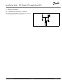
Connection of a pressure transmitter with 0-10 V output
Example of a pressure transmitter connection to S10. Pressure
transmitter can be connected in the same way to S9.
Connection of a pressure transmitter with 4-20 mA output
The 4-20 mA signal is converted to a 2-10 V signal by means of the
500 ohm resistor.
Example of a pressure transmitter connection to S10. Pressure
transmitter can be connected in the same way to S9.
Connection of 2 pressure switches
Wire cross section for sensor connections: Min. 0.4 mm².
Total cable length: Max. 200 m (all sensors incl. internal ECL 485
communication bus)
Cable lengths of more than 200 m may cause noise sensibility (EMC).
22
DEN-SMT/DK
VI.LG.M1.02
Danfoss District Energy
Installation Guide
ECL Comfort 310, application A361
2.5.6 Electrical connections, ECA 30 / 31
Terminal Terminal Description
ECL 310 ECA 30 /
31
4
30
Twisted pair
1
31
32
2
33
3
4
5
Type
(recomm.)
Cable 2 x
twisted pair
Twisted pair
Ext. room temperature
sensor*
ESM-10
* After an external room temperature sensor has been connected,
ECA 30 / 31 must be repowered.
The communication to the ECA 30 / 31 must be set up in the ECL
Comfort controller in 'ECA addr.'
The ECA 30 /31 must be set up accordingly.
After application setup the ECA 30 / 31 is ready after 2–5 min. A
progress bar in the ECA 30 / 31 is displayed.
ECA information message:
‘Application req. newer ECA’:
The software of your ECA does not comply with the software of your
ECL Comfort controller. Please contact your Danfoss sales office.
Some applications do not contain functions related to actual room
temperature. The connected ECA 30 / 31 will only function as remote
control.
Total cable length: Max. 200 m (all sensors incl. internal ECL 485
communication bus).
Cable lengths of more than 200 m may cause noise sensibility (EMC).
Danfoss District Energy
VI.LG.M1.02
DEN-SMT/DK
23
Installation Guide
ECL Comfort 310, application A361
2.5.7 Electrical connections, master / slave systems
The controller can be used as master or slave in master / slave
systems via the internal ECL 485 communication bus (2 x twisted
pair cable).
The ECL 485 communication bus is not compatible with the ECL
bus in ECL Comfort 110, 200, 300 and 301!
Terminal Description
30
Common terminal
31*
+12 V*, ECL 485 communication bus
32
A, ECL 485 communication bus
33
B, ECL 485 communication bus
Type
(recomm.)
Cable 2 x
twisted pair
* Only for ECA 30 / 31 and master / slave communication
Total cable length: Max. 200 m (all sensors incl. internal ECL 485
communication bus).
Cable lengths of more than 200 m may cause noise sensibility (EMC).
24
DEN-SMT/DK
VI.LG.M1.02
Danfoss District Energy
Installation Guide
ECL Comfort 310, application A361
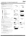
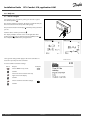
2.6 Inserting the ECL Application Key
2.6.1 Inserting the ECL Application Key
The ECL Application Key contains
•
the application and its subtypes,
•
currently available languages,
•
factory settings: e.g. schedules, desired temperatures,
limitation values etc. It is always possible to recover the factory
settings,
•
memory for user settings: special user / system settings.
After having powered-up the controller, different situations might
be existing:
1. The controller is new from the factory, the ECL Application Key
is not inserted.
2. The controller already runs an application. The ECL Application
Key is inserted, but the application needs to be changed.
3. A copy of the controllers settings is needed for configuring
another controller.
User settings are, among others, desired room temperature, desired
DHW temperature, schedules, heat curve, limitation values etc.
System settings are, among others, communication set-up, display
brightness etc.
Danfoss District Energy
VI.LG.M1.02
DEN-SMT/DK
25
Installation Guide
ECL Comfort 310, application A361
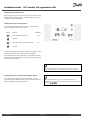
Application Key: Situation 1
The controller is new from the factory, the ECL Application Key
is not inserted.
An animation for the ECL Application Key insertion is displayed.
Insert the Application Key .
Application Key name and Version is indicated (example: A266
Ver. 1.03).
If the ECL Application Key is not suitable for the controller, a "cross"
is displayed over the ECL Application Key-symbol.
Action:
Purpose:
Examples:
Select language
Confirm
Select application
Confirm with ‘Yes’
Set 'Time & Date'
Turn and push the dial to select and
change 'Hours', 'Minutes', 'Date',
'Month' and 'Year'.
Choose ''Next'
Confirm with ‘Yes’
Go to ‘Aut. daylight’
Choose whether ‘Aut. daylight´ *
should be active or not
YES or NO
* ‘Aut. daylight’ is the automatic changeover between summer
and winter time.
Depending on the contents of the ECL Application Key, procedure
A or B is taking place:
A
The ECL Application key contains factory settings:
The controller reads / transfers data from the ECL Application Key
to ECL controller.
The application is installed, and the controller resets and starts up.
B
The ECL Application key contains changed system settings:
Push the dial repeatedly.
’NO’:
’YES*:
Only factory settings from the ECL Application Key will
be copied to the controller.
Special system settings (differing from the factory
settings) will be copied to the controller.
If the key contains user settings:
Push the dial repeatedly.
‘NO:
‘YES*:
Only factory settings from the ECL Application Key will
be copied to the controller.
Special user settings (differing from the factory settings)
will be copied to the controller.
* If ‘YES’ cannot be chosen, the ECL Application Key does not
contain any special settings.
Choose ‘Start copying’ and confirm with 'Yes'.
26
DEN-SMT/DK
VI.LG.M1.02
Danfoss District Energy
Installation Guide
ECL Comfort 310, application A361
Application Key: Situation 2
The controller already runs an application. The ECL Application
Key is inserted, but the application needs to be changed.
To change to another application on the ECL Application Key, the
current application in the controller must be erased (deleted).
Be aware that the Application Key must be inserted.
Action:
Purpose:
Examples:
Choose ‘MENU’ in any circuit
Confirm
Choose the circuit selector at the top
right corner in the display
Confirm
Choose ‘Common controller settings’
Confirm
Choose ‘Key functions’
Confirm
Choose ‘Erase application’
Confirm with ‘Yes’
The controller resets and is ready to be configured.
Follow the procedure described in situation 1.
Danfoss District Energy
VI.LG.M1.02
DEN-SMT/DK
27
Installation Guide
ECL Comfort 310, application A361
Application Key: Situation 3
A copy of the controllers settings is needed for configuring
another controller.
This function is used
•
for saving (backup) of special user and system settings
•
when another ECL Comfort controller of the same type (210 or
310) must be configured with the same application but user /
system settings differ from the factory settings.
How to copy to another ECL Comfort controller:
Action:
Purpose:
Examples:
Choose ‘MENU’
Confirm
Choose the circuit selector at the top
right corner in the display
Confirm
Choose 'Common controller settings'
Confirm
Go to ‘Key functions’
Confirm
Choose ‘Copy’
Confirm
Choose ‘To’.
*
‘ECL’ or ‘KEY’ will be indicated. Choose
’ECL’ or ‘KEY’.
’ECL’ or KEY’
Push the dial repeatedly to choose
copy direction
**
Choose ‘System settings’ or ‘User
‘NO’ or ‘YES’
settings’
Push the dial repeatedly to choose
‘Yes’ or ‘No’ in ‘Copy’. Push to confirm.
Choose ‘Start copying’
The Application Key or the controller
is updated with special system or user
settings.
*
‘ECL’:
‘KEY’:
Data will be copied from the Application Key to the
ECL Controller.
Data will be copied from the ECL Controller to the
Application Key.
**
‘NO’:
‘YES’:
28
The settings from the ECL controller will not be copied
to the Application Key or to the ECL Comfort controller.
Special settings (differing from the factory settings) will
be copied to the Application Key or to the ECL Comfort
controller. If YES can not be chosen, there are no special
settings to be copied.
DEN-SMT/DK
VI.LG.M1.02
Danfoss District Energy
Installation Guide
ECL Comfort 310, application A361
2.6.2 ECL Application Key, copying data
General principles
When the controller is connected and operating, you can check
and adjust all or some of the basic settings. The new settings can
be stored on the Key.
Factory settings can always be restored.
How to update the ECL Application Key after settings have
been changed?
All new settings can be stored on the ECL Application Key.
How to store factory setting in the controller from the
Application Key?
Please read the paragraph concerning Application Key, Situation
1: The controller is new from the factory, the ECL Application Key
is not inserted.
Make a note of new settings in the 'Settings overview' table.
How to store personal settings from the controller to the Key?
Please read the paragraph concerning Application Key, Situation 3:
A copy of the controllers settings is needed for configuring another
controller
Do not remove the ECL Application Key while copying. The data on
the ECL Application Key can be damaged!
As a main rule, the ECL Application Key should always remain in
the controller. If the Key is removed, it is not possible to change
settings.
Danfoss District Energy
It is possible to copy settings from one ECL Comfort controller to
another controller provided that the two controllers are from the same
series (210 or 310).
VI.LG.M1.02
DEN-SMT/DK
29
Installation Guide
ECL Comfort 310, application A361
2.7 Check list
Is the ECL Comfort controller ready for use?
Make sure that the correct power supply is connected to terminals 9 (Live) and 10 (Neutral).
Check that the required controlled components (actuator, pump etc.) are connected to the correct terminals.
Check that all sensors / signals are connected to the correct terminals (see 'Electrical connections').
Mount the controller and switch on the power.
Is the ECL Application Key inserted (see 'Inserting the Application Key').
Is the correct language chosen (see 'Language' in 'Common controller settings').
Is the time & date set correctly (see 'Time & Date' in 'Common controller settings').
Is the right application chosen (see 'Identifying the system type').
Check that all settings in the controller (see 'Settings overview') are set or that the factory settings comply with your
requirements.
Choose manual operation (see 'Manual control'). Check that valves open and close, and that required controlled
components (pump etc.) start and stop when operated manually.
Check that the temperatures / signals shown in the display match the actual connected components.
Having completed the manual operation check, choose controller mode (scheduled, comfort, saving or frost protection).
30
DEN-SMT/DK
VI.LG.M1.02
Danfoss District Energy
Installation Guide
ECL Comfort 310, application A361
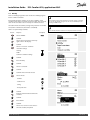
2.8 Navigation, ECL Application Key A361
Navigation, applications A361, circuit 1 and 2 (* application 361.2 only)
Home
Circuit 1, Heating
ID no.
Function
Circuit 2, Heating
ID no.
Function
MENU
Schedule
Settings
Flow temperature
11178
Return limit
Control par.
Danfoss District Energy
Selectable
Heat curve
Temp. max.
11178
Temp. max.
11177
Temp. min.
12177
Temp. min.
11300
High supp. T X2*
12300
High supp. T X2*
11301
High T max Y2*
12301
High T max Y2*
11302
Low supply T X1*
12302
Low supply T X1*
11303
Low T max Y1*
12303
Low T max Y1*
11031
High T out X1
12031
High T out X1
11032
Low limit Y1
12032
Low limit Y1
11033
Low T out X2
12033
Low T out X2
11034
High limit Y2
12034
High limit Y2
11035
Infl. - max.
12035
Infl. - max.
11036
Infl. - min.
12036
Infl. - min.
11037
Adapt. time
12037
Adapt. time
11085
Priority
12085
Priority
Flow / power limit
Optimization
Selectable
Heat curve
Actual
Actual
11119
Limit
High T out X1
12119
Limit
High T out X1
11117
Low limit Y1
12117
Low limit Y1
11118
Low T out X2
12118
Low T out X2
11116
High limit Y2
12116
High limit Y2
11112
Adapt. time
12112
Adapt. time
11113
Filter constant
12113
Filter constant
11109
Input type
12109
Input type
11115
Units
12115
Units
11011
Auto saving
12011
Auto saving
11012
Boost
12012
Boost
11013
Ramp
12013
Ramp
11014
Optimizer
12014
Optimizer
11026
Pre stop
12026
Pre stop
11021
Total stop
12021
Total stop
11179
Cut-out
12179
Cut-out
11174
Motor pr.
12174
Motor pr.
11184
Xp
12184
Xp
11185
Tn
12185
Tn
11186
M run
12186
M run
11187
Nz
12187
Nz
VI.LG.M1.02
DEN-SMT/DK
31
Installation Guide
ECL Comfort 310, application A361
Navigation, application A361, circuit 1 and circuit 2 continued
Home
MENU
Settings
Circuit 1, Heating
Pump control
ID no.
11314
Function
Chan.-over time
ID no.
12314
Function
Chan.-over time
11310
Retry time
12310
Retry time
11313
Stab. time
12313
Stab. time
11311
Change, duration
12311
Change, duration
11312
Change time
12312
Change time
11022
P exercise
12022
P exercise
Pressure
Refill water
Application
Input type
12327
Input type
11323
Time-out
12323
Time-out
11321
Pressure, des.
Pressure, des.
12321
11322
Pressure, diff.
12322
Pressure, diff.
11320
P exercise
12320
P exercise
11325
Valve delay
12325
Valve delay
11326
No. of pumps
12326
No. of pumps
11017
Demand offset
11023
M exercise
12023
M exercise
11052
DHW priority
12052
DHW priority
11077
P frost T
12077
P frost T
11078
P heat T
12078
P heat T
11093
Frost pr. T
12093
Frost pr. T
11141
Ext. input
Ext. input
12141
11142
Ext. mode
12142
Ext. mode
11189
Min. act. time
12189
Min. act. time
Selectable
Temp. monitor.
Clear alarm
Influence overview
Pressure
11327
Holiday
Alarm
Circuit 2, Heating
Selectable
11147
Upper difference
12147
Upper difference
11148
Lower difference
12148
Lower difference
11149
Delay
12149
Delay
11150
Lowest temp.
12150
Lowest temp.
11315
Circ. pumps
12315
Circ. pumps
11324
Refill water
12324
Refill water
Alarm overview
Selectable
Selectable
Des. flow T
Return lim.
Flow / power lim.
Return lim.
Flow / power lim.
Holiday
Holiday
Ext. override
Ext. override
Boost
Boost
Ramp
Ramp
Slave, demand
32
DEN-SMT/DK
Heating cut-out
Heating cut-out
DHW priority
DHW priority
VI.LG.M1.02
Danfoss District Energy
Installation Guide
ECL Comfort 310, application A361
Navigation, application A361, Common controller settings (* application A361.2 only)
Home
MENU
Time & Date
Holiday
Input overview 1
Input overview 2
Log 1 (sensors)
Log 2 (sensors)
Outdoor T
Supply T*
Heating flow & des.
Heat return T & limit
Static pressure
Outdoor T
Supply T*
Heating flow & des.
Heat return T & limit
Static pressure
Common controller settings
ID no. Function
Selectable
Selectable
Outdoor T
Supply T*
Heat flow T
Heat return T
Static pressure
S7 status
Outdoor T
Supply T*
Heat flow T
Heat return T
Static pressure
S8 status
Log today
Log yesterday
Log 2 days
Log 4 days
Log today
Log yesterday
Log 2 days
Log 4 days
M1, P1, P2, M2, P3, P5, V1, V2,
P4, A1
Erase application
Output override
Key functions
New application
Application
Factory setting
System settings
User settings
Go to factory
To
System settings
User settings
Start copying
Copy
System
Key overview
ECL version
Code no.
Hardware
Software
Build no.
Serial no.
MAC
Production week
Extension
Ethernet
M-bus config
Energy Meters
Display
Communication
Language
Danfoss District Energy
VI.LG.M1.02
60058
60059
38
2048
2150
2151
2050
Selectable
Selectable
Backlight
Contrast
Modbus addr.
ECL 485 addr.
Service pin
Ext. reset
Language
DEN-SMT/DK
33
Installation Guide
ECL Comfort 310, application A361
3.0 Daily use
3.1 How to navigate
You navigate in the controller by turning the dial left or right to
the desired position ( ).
The dial has a built-in accellerator. The faster you turn the dial, the
faster it reaches the limits of any wide setting range.
The position indicator in the display ( ) will always show you where
you are.
Push the dial to confirm your choices ( ).
The display examples are from a two-circuit application: One
heating circuit ( ) and one domestic hot-water (DHW) circuit ( ).
The examples might differ from your application.
Heating circuit ( ):
Some general settings which apply to the entire controller are
located in a specific part of the controller.
DHW circuit ( );
Circuit selector
To enter ‘Common controller settings’:
Action:
Purpose:
Examples:
Choose ‘MENU’ in any circuit
Confirm
Choose the circuit selector at the top
right corner in the display
Confirm
Choose ‘Common controller settings’
Confirm
34
DEN-SMT/DK
VI.LG.M1.02
Danfoss District Energy
Installation Guide
ECL Comfort 310, application A361
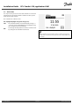
3.2 Understanding the controller display
Choosing a favorite display
Your favorite display is the display you have chosen as the default
display. The favorite display will give you a quick overview of the
temperatures or units that you want to monitor in general.
If the dial has not been activated for 20 min., the controller will
revert to the overview display you have chosen as favorite.
Heating circuit
Overview display 1 informs about:
actual outdoor temperature, controller mode,
actual room temperature, desired room temperature.
Change between displays by turning the dial until you reach the
display selector (
) at bottom right side of the display. Turn the dial
and push to choose your favorite overview display.
Overview display 1:
Overview display 2:
Overview display 3:
Overview display 4:
Overview display 2 informs about:
actual outdoor temperature, trend in outdoor temperature,
controller mode, max. and min. outdoor temperatures since
midnight as well as desired room temperature.
Overview display 3 informs about:
date, actual outdoor temperature, controller mode, time, desired
room temperature as well as shows the comfort schedule of the
current day.
Overview display 4 informs about:
state of the controlled components, actual flow temperature,
(desired flow temperature), controller mode, return temperature
(limitation value).
Dependent on the chosen display, the overview displays for the
heating circuit inform you about:
• actual outdoor temperature (-0.5)
• controller mode ( )
• actual room temperature (24.5)
• desired room temperature (20.7 °C)
• trend in outdoor temperature ( )
• min. and max. outdoor temperatures since midnight ( )
• date (23.02.2010)
• time (7:43)
• comfort schedule of the current day (0 - 12 - 24)
• state of the controlled components (M2, P2)
• actual flow temperature (49 °C), (desired flow temperature (31))
• return temperature (24 °C) (limitation temperature (50))
The setting of the desired room temperature is important even if a
room temperature sensor / Remote Control Unit is not connected.
If the temperature value is displayed as
"- -" the sensor in question is not connected.
"- - -" the sensor connection is short-circuited.
Danfoss District Energy
VI.LG.M1.02
DEN-SMT/DK
35
Installation Guide
ECL Comfort 310, application A361
Setting the desired temperature
Depending on the chosen circuit and mode, it is possible to enter
all daily settings directly from the overview displays (see also the
next page concerning symbols).
Setting the desired room temperature
The desired room temperature can easily be adjusted in the
overview displays for the heating circuit.
Action:
Purpose:
Desired room temperature
Examples:
20.5
Confirm
Adjust the desired room temperature
21.0
Confirm
This overview display informs about outdoor temperature, actual
room temperature as well as desired room temperature.
The display example is for comfort mode. If you want to change
the desired room temperature for saving mode, choose the mode
selector and select saving.
The setting of the desired room temperature is important even if a
room temperature sensor / Remote Control Unit is not connected.
Setting the desired room temperature, ECA 30 / ECA 31
The room desired temperature can be set exactly as in the
controller. However, other symbols can be present in the display
(please see 'What do the symbols mean?').
36
DEN-SMT/DK
With the ECA 30 / ECA 31 you can override the desired room
temperature set in the controller temporarily by means of the override
functions:
VI.LG.M1.02
Danfoss District Energy
Installation Guide
ECL Comfort 310, application A361
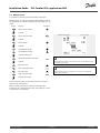
3.3 What do the symbols mean?
Symbol
Description
Symbol
Description
Sensor not connected or not used
Outdoor temp.
Sensor connection short-circuited
Room temp.
Temperature
7-23
Fixed comfort day (holiday)
DHW temp.
Active influence
Position indicator
No influence
Scheduled mode
Additional symbols, ECA 30 / 31:
Comfort mode
Saving mode
Symbol
Mode
Description
ECA Remote Control Unit
Frost protection mode
Relative humidity indoor
Manual mode
Day off
Heating
DHW
Holiday
Circuit
Common controller settings
Relaxing (extended comfort period)
Pump ON
Pump OFF
Actuator opens
Going out (extended saving period)
Controlled
component
Actuator closes
Alarm
Display selector
Max. and min. value
Trend in outdoor temperature
Wind speed sensor
Danfoss District Energy
VI.LG.M1.02
DEN-SMT/DK
37
Installation Guide
ECL Comfort 310, application A361
3.4 Monitoring temperatures and system components
Heating circuit
The overview display in the heating circuit ensures a quick
overview of the actual and (desired) temperatures as well as the
actual state of the system components.
Display example:
49 °C
(31)
24 °C
(50)
Flow temperature
Desired flow temperature
Return temperature
Return temperature limitation
Input overview
Another option to get a quick overview of measured temperatures
is the 'Input overview' which is visible in the common controller
settings (how to enter the common controller settings, see
‘Introduction to common controller settings’.)
As this overview (see display example) only states the measured
actual temperatures, it is read-only.
38
DEN-SMT/DK
VI.LG.M1.02
Danfoss District Energy
Installation Guide
ECL Comfort 310, application A361
3.5 Manual control
It is possible to manually control the installed components.
Manual control can only be selected in favorite displays in which
the symbols for the controlled components (valve, pump etc.) are
visible.
Action:
Purpose:
Examples:
Choose mode selector
Confirm
Controlled components
Choose manual mode
Circuit selector
Confirm
Choose pump
Confirm
Switch ON the pump
Switch OFF the pump.
Confirm pump mode
Choose motorized control valve
During manual operation, all control functions are deactivated. Frost
protection is not active.
Confirm
Open the valve
Stop opening the valve
Close the valve
When manual control is selected for one circuit, it is automatically
selected for all circuits!
Stop closing the valve
Confirm valve mode
To leave manual control, use the mode selector to select the
desired mode. Push the dial.
Manual control is typically used when commisioning the
installation. The controlled components, valve, pump etc., can be
controlled for correct function.
Danfoss District Energy
VI.LG.M1.02
DEN-SMT/DK
39
Installation Guide
ECL Comfort 310, application A361
3.6 Schedule
3.6.1 Set your schedule
The schedule consists of a 7-day week:
M = Monday
T = Tuesday
W = Wednesday
T = Thursday
S
= Friday
= Saturday
S
= Sunday
F
The schedule will day-by-day show you the start and stop times of
your comfort periods (heating / DHW circuits).
Changing your schedule:
Action:
Purpose:
Examples:
Choose 'MENU' in any of the overview
displays
Confirm
Confirm the choice 'Schedule'
Choose the day to change
Confirm*
T
Go to Start1
Confirm
Adjust the time
Confirm
Go to Stop1, Start2 etc. etc.
Return to 'MENU'
Confirm
Choose 'Yes' or 'No' in 'Save'
Each circuit has its own schedule. To change to another circuit, go to
'Home', turn the dial and choose the desired circuit.
Confirm
* Several days can be marked
The chosen start and stop times will be valid for all the chosen days
(in this example Thursday and Saturday).
The start and stop times can be set in half-hourly (30 min. ) intervals.
You can set max. 3 comfort periods a day. You can delete a comfort
period by setting start and stop times to the same value.
40
DEN-SMT/DK
VI.LG.M1.02
Danfoss District Energy
Installation Guide
ECL Comfort 310, application A361
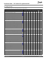
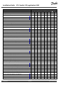
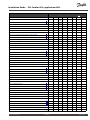
4.0 Settings overview
It is recommendable to make a note of any changed settings in the empty columns.
Setting
ID
Factory settings in circuit(s)
Page
1
3
45
Heat curve
Temp. max. (flow temp. limit, max.) — A361.1
11178
Temp. min. (flow temp. limit, min.)
11177
46
90 °C
46
10 °C
Heat curve
47
Temp. max. (flow temp. limit, max.) — A361.2
48
Temp. min. (flow temp. limit, min.)
11177
48
10 °C
High supp. T X2 (high value of supply temp.) — A361.2
11300
48
150 °C
High T max Y2 (high value of max limitation) — A361.2
11301
48
95 °C
Low supply T X1(low value of supply temp.) — A361.2
11302
49
70 °C
Low T max Y1 (low value of max limitation) — A361.2
11303
49
50 °C
High T out X1 (return temp. limitation, high limit, X-axis)
11031
50
15 °C
Low limit Y1 (return temp. limitation, low limit, Y-axis)
11032
50
40 °C
Low T out X2 (return temp. limitation, low limit, X-axis)
11033
50
-15 °C
High limit Y2 (return temp. limitation, high limit, Y-axis)
11034
51
60 °C
Infl. - max. (return temp. limitation - max. influence)
11035
51
0.0
Infl. - min. (return temp. limitation - min. influence)
11036
51
0.0
Adapt. time (adaptation time)
11037
51
25 s
Priority (priority for return temp. limitation)
11085
52
OFF
High T out X1 (flow / power limitation, high limit, X-axis)
11119
53
Low limit Y1 (flow / power limitation, low limit, Y-axis)
11117
54
Low T out X2 (flow / power limitation, low limit, X-axis)
11118
54
High limit Y2 (flow / power limitation, high limit, Y-axis)
11116
54
Adapt. time (adaptation time)
11112
54
15 °C
999.9
l/h
-15 °C
999.9
l/h
OFF
Filter constant
11113
54
10
Input type
11109
55
OFF
Units
11115
55
l/h
Auto saving (saving temp. dependent on outdoor temp.)
11011
56
-15 °C
Boost
11012
56
OFF
Ramp (reference ramping)
11013
57
OFF
Optimizer (optimizing time constant)
11014
57
OFF
Pre-stop (optimized stop time)
11026
58
ON
Total stop
11021
58
OFF
Cut-out (limit for heating cut-out)
11179
59
20 °C
Motor pr. (motor protection)
11174
60
OFF
Xp (proportional band)
11184
60
80 K
Tn (integration time constant)
11185
60
30 s
M run (running time of the motorized control valve)
11186
60
50 s
Nz (neutral zone)
11187
61
3K
Chan.-over time (change-over time)
11314
62
5s
Retry time
11310
62
20 m
Stab. time (stabilization time)
11313
62
15 s
Danfoss District Energy
2
VI.LG.M1.02
DEN-SMT/DK
41
Installation Guide
ECL Comfort 310, application A361
Setting
ID
Factory settings in circuit(s)
Page
1
Change, duration
11311
63
2
Change time (changeover time)
11312
63
12
P exercise (pump exercise)
11022
63
OFF
Input type
11327
65
OFF
Time-out
11323
65
20 s
Pressure, des. (desired pressure)
11321
65
3.0 bar
Pressure, diff. (switching difference)
11322
66
1.5 bar
P exercise (pump exercise)
11320
66
OFF
Valve delay
11325
66
1s
No. of pumps
11326
66
1
Demand offset
11017
68
OFF
M exercise (valve exercise)
11023
68
OFF
DHW priority (closed valve / normal operation)
11052
68
OFF
P frost T
11077
68
2 °C
P heat T (heat demand)
11078
69
20 °C
Frost pr. T (frost protection temperature)
11093
69
10 °C
Ext. input (external override) — A361.1 / A361.2
11141
70
OFF
Ext. mode (external override mode)
11142
70
SAVING
Min. act. time (min. activation time gear motor)
11189
71
10
Upper difference
11147
72
OFF
Lower difference
11148
72
OFF
Delay
11149
73
10 m
Lowest temp.
11150
73
30 °C
Circ. pumps
11315
73
Refill water
11324
74
75
Heat curve
Temp. max. (flow temp. limit, max.) — A361.1
12178
76
90 °C
Temp. min. (flow temp. limit, min.)
12177
76
10 °C
Heat curve
77
Temp. max. (flow temp. limit, max.) — A361.2
78
Temp. min. (flow temp. limit, min.)
12177
78
10 °C
High supp. T X2 (high value of supply temp.) — A361.2
12300
78
150 °C
High T max Y2 (high value of max limitation) — A361.2
12301
78
95 °C
Low supply T X1(low value of supply temp.) — A361.2
12302
79
70 °C
Low T max Y1 (low value of max limitation) — A361.2
12303
79
50 °C
15 °C
High T out X1 (return temp. limitation, high limit, X-axis)
12031
80
Low limit Y1 (return temp. limitation, low limit, Y-axis)
12032
80
40 °C
Low T out X2 (return temp. limitation, low limit, X-axis)
12033
80
-15 °C
High limit Y2 (return temp. limitation, high limit, Y-axis)
12034
81
60 °C
Infl. - max. (return temp. limitation - max. influence)
12035
81
0.0
Infl. - min. (return temp. limitation - min. influence)
12036
81
0.0
Adapt. time (adaptation time)
12037
81
25 s
Priority (priority for return temp. limitation)
12085
82
OFF
DEN-SMT/DK
3
64
Pressure
42
2
VI.LG.M1.02
Danfoss District Energy
Installation Guide
ECL Comfort 310, application A361
Setting
ID
Factory settings in circuit(s)
Page
1
High T out X1 (flow / power limitation, high limit, X-axis)
12119
83
Low limit Y1 (flow / power limitation, low limit, Y-axis)
12117
84
Low T out X2 (flow / power limitation, low limit, X-axis)
12118
84
High limit Y2 (flow / power limitation, high limit, Y-axis)
12116
84
2
Adapt. time (adaptation time)
12112
84
15 °C
999.9
l/h
-15 °C
999.9
l/h
OFF
Filter constant
12113
84
10
Input type
12109
85
OFF
Units
12115
85
l/h
Auto saving (saving temp. dependent on outdoor temp.)
12011
86
-15 °C
Boost
12012
86
OFF
Ramp (reference ramping)
12013
87
OFF
Optimizer (optimizing time constant)
12014
87
OFF
Pre-stop (optimized stop time)
12026
88
ON
Total stop
12021
88
OFF
Cut-out (limit for heating cut-out)
12179
89
20 °C
Motor pr. (motor protection)
12174
90
OFF
Xp (proportional band)
12184
90
40 K
Tn (integration time constant)
12185
90
20 s
M run (running time of the motorized control valve)
12186
90
20 s
Nz (neutral zone)
12187
91
3K
Chan.-over time (change-over time)
12314
93
5s
Retry time
12310
93
20 m
Stab. time (stabilization time)
12313
93
15 s
Change, duration
12311
94
2
Change time (changeover time)
12312
94
12
P exercise (pump exercise)
12022
94
OFF
95
Pressure
Input type
12327
96
OFF
Time-out
12323
96
20 s
Pressure, des. (desired pressure)
12321
96
3.0 bar
Pressure, diff. (switching difference)
12322
97
1.5 bar
P exercise (pump exercise)
12320
97
OFF
Valve delay
12325
97
1s
No. of pumps
12326
97
1
M exercise (valve exercise)
12023
99
OFF
DHW priority (closed valve / normal operation)
12052
99
OFF
P frost T
12077
99
2 °C
P heat T (heat demand)
12078
99
20 °C
10 °C
Frost pr. T (frost protection temperature)
12093
100
Ext. input (external override) — A361.1 / A361.2
12141
100
OFF
Ext. mode (external override mode)
12142
101
SAVING
Min. act. time (min. activation time gear motor)
12189
101
3
Upper difference
12147
102
OFF
Lower difference
12148
102
OFF
Danfoss District Energy
3
VI.LG.M1.02
DEN-SMT/DK
43
Installation Guide
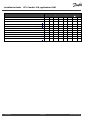
Setting
ECL Comfort 310, application A361
ID
Factory settings in circuit(s)
Page
1
44
2
Delay
12149
103
10 m
Lowest temp.
12150
103
30 °C
3
Circ. pumps
12315
103
Refill water
12324
104
Backlight (display brightness)
60058
113
5
Contrast (display contrast)
60059
113
3
Modbus addr.
38
113
1
ECL 485 addr. (master / slave address)
2048
114
15
Service Pin
2150
114
0
Ext. reset
2151
114
0
Language
2050
114
English
DEN-SMT/DK
VI.LG.M1.02
Danfoss District Energy
Installation Guide
ECL Comfort 310, application A361
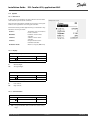
5.0 Settings, circuit 1
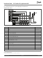
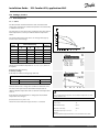
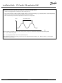
5.1 Flow temperature
5.1.1 A361.1
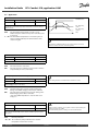
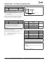
The ECL Comfort controller determines and controls the flow
temperature related to the outdoor temperature. This relationship
is called the heat curve.
Desired flow temperature
°C
The heat curve is set by means of 6 coordinate points. The desired
flow temperature is set at 6 pre-defined outdoor temperature
values.
110
100
The shown value for the heat curve is an average value (slope),
based on the actual settings.
Outdoor
temp.
80
60
40
Your
settings
Desired flow temp.
A
B
C
-30 °C
45 °C
75 °C
95 °C
-15 °C
40 °C
60 °C
90 °C
-5 °C
35 °C
50 °C
80 °C
0 °C
32 °C
45 °C
70 °C
5 °C
30 °C
40 °C
60 °C
15 °C
25 °C
28 °C
35 °C
C
B
A
20
-50 -40 -30 -20 -10
0
10
20
Adjust the desired flow temperature at -30, -15, -5, 0, 5, and 15 °C,
if required.
A: Example for floor heating
B: Factory settings
C: Example for radiator heating (high demand)
Heat curve
Circuit
Setting range
1
Read-out only
Factory setting
Push the dial to enter / change the coordinates of the heat curve.
The heat curve represents the desired flow temperatures at
different outdoor temperature and at a desired room temperature
of 20 °C.
If the desired room temperature is changed, the desired flow
temperature also changes:
The calculated flow temperature can be influenced by the ‘Boost’ and
‘Ramp’ functions etc.
(Desired room T - 20) × HC × 2.5
where "HC" is the Heat Curve slope and "2.5" is a constant.
Example:
Heat curve:
1.0
Desired flow temp.:
50 °C
Desired room temp.:
22 °C
Calculation (22–20) × 1.0 × 2.5 =
5
Result:
The desired flow temperature will be corrected from 50 °C to 55 °C.
Danfoss District Energy
VI.LG.M1.02
DEN-SMT/DK
45
Installation Guide
ECL Comfort 310, application A361
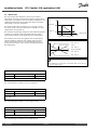
Max. limitation of the desired flow temperature:
In the application A361.1 the max. limitation value is selectable
in ‘Temp. max.’.
Temp. max. (flow temp. limit, max.) — A361.1
11178
Circuit
Setting range
Factory setting
1
10 ... 150 °C
90 °C
The setting for ‘Temp. max.’ has higher priority than ‘Temp. min.’.
Set the max. flow temperature for the system. The desired flow
temperature will not be higher than this setting. Adjust the factory
setting, if required.
11177
Temp. min. (flow temp. limit, min.)
Circuit
Setting range
Factory setting
1
10 ... 150 °C
10 °C
Set the min. flow temperature for the system. The desired flow
temperature will not be lower than this setting. Adjust the factory
setting, if required.
‘Temp. min.’ is overruled if 'Total stop' is active in Saving mode or
'Cut-out' is active.
‘Temp. min.’ can be overruled by the influence from the return
temperature limitation (see 'Priority').
The setting for ‘Temp. max.’ has higher priority than ‘Temp. min.’.
46
DEN-SMT/DK
VI.LG.M1.02
Danfoss District Energy
Installation Guide
ECL Comfort 310, application A361
5.1.2 A361.2
Desired flow temperature
The ECL Comfort controller determines and controls the flow
temperature related to the supply temperature (S2). This
relationship is set in the controller.
°C
The heat curve is set in all coordinate points to the max. desired
flow temperature (150 °C). The desired flow temperature will
always be in relation to the supply temperature (S2).
The shown value for the heat curve is an average value (slope),
based on the actual settings.
Outdoor temp.
Factory setting
-30 °C
150 °C
-15 °C
150 °C
-5 °C
150 °C
0 °C
150 °C
5 °C
150 °C
15 °C
150 °C
Y2
Y1
Your settings
°C Supply temp. (S2)
X1
X2
Adjust the desired flow temperature at -30, -15, -5, 0, 5, and 15 °C,
if required.
Heat curve
Circuit
Setting range
1
Read-out only
Factory setting
The factory setting (a general desired flow temperature of 150 °C) is
limited to a max. value based on the supply temperature (S2) and
the settings in parameters ‘High supp. T X2’, ‘High T max Y2’, ‘Low
supply T X1’ and ‘Low T max Y1’.
Desired flow temperature
°C
95
50
58
°C Supply temp. (S2)
85
70
150
The above heat curve is an example of a supply temperature (S2) of
85 °C. The desired flow temperature (58 °C) is based on the set-up of
the relationship between the supply temperature (S2) and the desired
flow temperature.
Danfoss District Energy
VI.LG.M1.02
DEN-SMT/DK
47
Installation Guide
ECL Comfort 310, application A361
Max. limitation of the desired flow temperature:
In the application A361.2 the desired flow temperature or max.
limitation value depends on the supply temperature (S2). The
relationship is set in the four settings ‘High supp. T X2’, ‘High T max
Y2’, ‘Low supply T X1’ and ‘Low T max Y1’.
When setting the heat curve coordinates as described in the
section 'A361.1’, the desired flow temperature can be limited to a
maximum according to the supply temperature (S2).
Temp. max. (flow temp. limit, max.) — A361.2
Circuit
Setting range
1
Read-out only
Factory setting
The supply temperature (S2) determines the desired flow
temperature. The value is calculated on basis of the settings in
the following parameters: 'High supp. T X2', 'High T max Y2', 'Low
supply T X1' and 'Low T max Y1'.
11177
Temp. min. (flow temp. limit, min.)
Circuit
Setting range
Factory setting
1
10 ... 150 °C
10 °C
Set the min. flow temperature for the system. The desired flow
temperature will not be lower than this setting. Adjust the factory
setting, if required.
‘Temp. min.’ is overruled if 'Total stop' is active in Saving mode or
'Cut-out' is active.
‘Temp. min.’ can be overruled by the influence from the return
temperature limitation (see 'Priority').
The setting for ‘Temp. max.’ has higher priority than ‘Temp. min.’.
High supp. T X2 (high value of supply temp.) — A361.2
11300
Circuit
Setting range
Factory setting
1
10 ... 150 °C
150 °C
Set the high value for the supply temperature in relation to the
desired max. flow temperature. When the supply temperature is
above the set value, the max. limitation of the flow temperature is
the Y2 value. When the supply temperature is below the set value,
the max. limitation of the flow temperature will be lower.
High T max Y2 (high value of max limitation) — A361.2
11301
Circuit
Setting range
Factory setting
1
10 ... 150 °C
95 °C
Set the high value for the max. limitation of the desired flow
temperature.
48
DEN-SMT/DK
VI.LG.M1.02
Danfoss District Energy
Installation Guide
ECL Comfort 310, application A361
Low supply T X1(low value of supply temp.) — A361.2
11302
Circuit
Setting range
Factory setting
1
10 ... 150 °C
70 °C
Set the low value for the supply temperature in relation to the
desired max. flow temperature. When the supply temperature is
below the set value, the max. limitation of the flow temperature is
the Y1 value. When the supply temperature is above the set value,
the max. limitation of the flow temperature will be higher.
Low T max Y1 (low value of max limitation) — A361.2
11303
Circuit
Setting range
Factory setting
1
10 ... 150 °C
50 °C
Set the low value for the max. limitation of the desired flow
temperature.
Set-up procedure when the supply temperature (S2) has to limit
the desired flow temperature to a maximum:
1. Choose ‘Heat curve’.
2. Set the desired flow temperature in all 6 coordinates (-30 °C, -15
°C etc.) to the desired values.
Result:
The desired flow temperature will be in relation to the outdoor
temperature but will be limited to a maximum according the
settings in ‘High supp. T X2’, ‘High T max Y2’, ‘Low supply T X1’ and
‘Low T max Y1’.
Danfoss District Energy
The example shows the max. limitation of the desired flow
temperature when the supply temperature (S2) is 105 °C.
VI.LG.M1.02
DEN-SMT/DK
49
Installation Guide
ECL Comfort 310, application A361
5.2 Return limit
The return temperature limitation is based on the outdoor
temperature. Typically in district heating systems a higher return
temperature is accepted at a decrease in outdoor temperature. The
relationship between the return temperature limits and outdoor
temperature is set in two coordinates.
The outdoor temperature coordinates are set in 'High T out X1'
and 'Low T out X2'. The return temperature coordinates are set in
'High limit Y2' and 'Low limit Y1'.
Return temperature limitation
°C
High limit Y2
60
Low limit Y1
40
The controller automatically changes the desired flow temperature
to obtain an acceptable return temperature when the return
temperature falls below or gets higher than the calculated limit.
This limitation is based on a PI regulation where P ('Infl.' factor)
responds quickly to deviations and I ('Adapt. time') responds
slower and over time removes the small offsets between the
desired and actual values. This is done by changing the desired
flow temperature.
-15
15
°C
Outdoor temp.
Low T out X2 High T out X1
Influence
‘Infl. - min.’ > 0
‘Limit’
‘Infl. - max.’ > 0
Return temperature
‘Infl. - max.’ < 0
‘Infl. - min.’ < 0
If the ‘Infl.’ factor is too high and / or the ‘Adapt. time’ too low, there is
a risk of unstable control.
High T out X1 (return temp. limitation, high limit, X-axis)
11031
Circuit
Setting range
Factory setting
1
-60 ... 20 °C
15 °C
Set the outdoor temperature for the low return temperature limitation.
The corresponding Y coordinate is set in 'Low limit Y1'.
11032
Low limit Y1 (return temp. limitation, low limit, Y-axis)
Circuit
Setting range
Factory setting
1
10 ... 150 °C
40 °C
Set the return temperature limitation referring to the outdoor temperature
set in 'High T out X1'.
The corresponding X coordinate is set in 'High T out X1'.
Low T out X2 (return temp. limitation, low limit, X-axis)
11033
Circuit
Setting range
Factory setting
1
-60 ... 20 °C
-15 °C
Set the outdoor temperature for the high return temperature limitation.
The corresponding Y coordinate is set in 'High limit Y2'.
50
DEN-SMT/DK
VI.LG.M1.02
Danfoss District Energy
Installation Guide
ECL Comfort 310, application A361
High limit Y2 (return temp. limitation, high limit, Y-axis)
11034
Circuit
Setting range
Factory setting
1
10 ... 150 °C
60 °C
Set the return temperature limitation referring to the outdoor temperature
set in 'Low T out X2'.
The corresponding X coordinate is set in 'Low T out X2'.
Infl. - max. (return temp. limitation - max. influence)
11035
Circuit
Setting range
Factory setting
1
-9.9 ... 9.9
0.0
Determines how much the desired flow temperature will be influenced if the
return temperature is higher than the calculated limit.
Influence higher than 0:
The desired flow temperature is increased, when the return
temperature gets higher than the calculated limit.
Normally, this setting is lower than 0 in district heating systems to
avoid a too high return temperature.
Typically, this setting is 0 in boiler systems because a higher return
temperature is acceptable (see also 'Infl. - min.').
Influence lower than 0:
The desired flow temperature is decreased, when the return
temperature gets higher than the calculated limit.
Infl. - min. (return temp. limitation - min. influence)
Example
The return limit is active above 50 °C.
The influence is set to -2.0.
The actual return temperature is 2 degrees too high.
Result:
The desired flow temperature is changed by -2.0 x 2 = -4.0 degrees.
11036
Circuit
Setting range
Factory setting
1
-9.9 ... 9.9
0.0
Determines how much the desired flow temperature will be influenced if the
return temperature is lower than the calculated limit.
Influence higher than 0:
The desired flow temperature is increased, when the return
temperature gets below the calculated limit.
Example
The return limit is active below 50 °C.
The influence is set to -3.0.
The actual return temperature is 2 degrees too low.
Result:
The desired flow temperature is changed by -3.0 x 2 = -6.0 degrees.
Normally, this setting is 0 in district heating systems because a lower
return temperature is acceptable.
Typically, this setting is higher than 0 in boiler systems to avoid a too
low return temperature (see also 'Infl. - max.').
Influence lower than 0:
The desired flow temperature is decreased, when the return
temperature gets below the calculated limit.
11037
Adapt. time (adaptation time)
Circuit
Setting range
Factory setting
1
OFF / 1 ... 50 s
25 s
The adaptation function can correct the desired flow temperature
with max. 8 K.
Controls how fast the return temperature adapts to the desired return
temperature limit (I control).
OFF:
1:
The control function is not influenced by the ‘Adapt.
time’.
The desired temperature is adapted quickly.
50:
The desired temperature is adapted slowly.
Danfoss District Energy
VI.LG.M1.02
DEN-SMT/DK
51
Installation Guide
ECL Comfort 310, application A361
11085
Priority (priority for return temp. limitation)
Circuit
Setting range
Factory setting
1
OFF / ON
OFF
Choose whether the return temperature limitation should overrule the set
min. flow temperature ‘Temp. min.’ .
52
ON:
The min. flow temperature limit is overruled.
OFF:
The min. flow temperature limit is not overruled.
DEN-SMT/DK
VI.LG.M1.02
Danfoss District Energy
Installation Guide
ECL Comfort 310, application A361
5.3 Flow / power limit
A flow or energy meter can be connected to the ECL controller in
order to limit the flow or consumed power. The signal from the
flow or energy meter is based on M-bus signal.
Flow / power limitation
The flow / power limitation can be based on the outdoor
temperature. Typically, in district heating systems a higher flow or
power is accepted at lower outdoor temperatures.
High limit Y2
The relationship between the flow or power limits and the outdoor
temperature is set in two coordinates.
Low limit Y1
The outdoor temperature coordinates are set in 'High T out X1'
and 'Low T out X2'.
-15
15
°C
Outdoor temp.
Low T out X2 High T out X1
The flow or power coordinates are set in 'Low limit Y1' and 'High
limit Y2'. Based on these settings, the controller calculates the
limitation value.
When the flow / power gets higher than the calculated limit, the
controller gradually reduces the desired flow temperature to obtain
an acceptable max. flow or power consumption.
Flow / power
limitation
Limit
°C
Desired flow
temp.
Time
If the ‘Adapt. time’ is too high, there is a risk of unstable control.
11110
Actual (actual flow or power)
Circuit
Setting range
1
Read-out only
Factory setting
The value is the actual flow or power based on the signal from flow / energy
meter, converted in the controller.
11111
Limit (limitation value)
Circuit
Setting range
1
Read-out only
Factory setting
The value is the calculated limitation value.
High T out X1 (flow / power limitation, high limit, X-axis)
11119
Circuit
Setting range
Factory setting
1
-60 ... 20 °C
15 °C
Set the outdoor temperature for the low flow / power limitation.
The corresponding Y coordinate is set in 'Low limit Y1'.
Danfoss District Energy
VI.LG.M1.02
DEN-SMT/DK
53
Installation Guide
ECL Comfort 310, application A361
11117
Low limit Y1 (flow / power limitation, low limit, Y-axis)
Circuit
Setting range
Factory setting
1
0.0 ... 999.9 l/h
999.9 l/h
The limitation function can overrule the set 'Temp. min' of the desired
flow temperature.
Set the flow / power limitation referring to the outdoor temperature set in
'High T out X1'.
The corresponding X coordinate is set in 'High T out X1'.
11118
Low T out X2 (flow / power limitation, low limit, X-axis)
Circuit
Setting range
Factory setting
1
-60 ... 20 °C
-15 °C
Set the outdoor temperature for the high flow / power limitation.
The corresponding Y coordinate is set in 'High limit Y2'.
11116
High limit Y2 (flow / power limitation, high limit, Y-axis)
Circuit
Setting range
Factory setting
1
0.0 ... 999.9 l/h
999.9 l/h
Set the flow / power limitation referring to the outdoor temperature set
in 'Low T out X2'.
The corresponding X coordinate is set in 'Low T out X2'.
11112
Adapt. time (adaptation time)
Circuit
Setting range
Factory setting
1
OFF / 1 ... 50 s
OFF
Controls how fast the flow / power limitation adapts to the desired
limitation.
OFF:
1:
The control function is not influenced by the ‘Adapt.
time’.
The desired temperature is adapted slowly.
50:
The desired temperature is adapted quickly.
11113
Filter constant
Circuit
Setting range
Factory setting
1
1 ... 50
10
The actual filter dampens the flow / power input data by the set factor.
54
1:
No filtering.
2:
Fast (low filter constant)
50:
Slow (high filter constant)
DEN-SMT/DK
VI.LG.M1.02
Danfoss District Energy
Installation Guide
ECL Comfort 310, application A361
11109
Input type
Circuit
Setting range
Factory setting
1
OFF / EM1 ... EM5
OFF
Choice of M-bus signal from energy meter number 1 ... 5.
OFF:
No M-bus signal acquired.
EM1 ... EM5: Energy meter number.
11115
Units
Circuit
Setting range
Factory setting
1
See the list
l/h
Choice of units for measured values.
Flow values are expressed as l/h or m³/h
Power values are expressed as kW, MW or GW.
Danfoss District Energy
List for setting range of 'Units':
l/h
m³/h
kW
MW
GW
VI.LG.M1.02
DEN-SMT/DK
55
Installation Guide
ECL Comfort 310, application A361
5.4 Optimization
Auto saving (saving temp. dependent on outdoor temp.)
Reduction
11011
Circuit
Setting range
Factory setting
1
OFF / -29 ... 10 °C
-15 °C
Below the set value for the outdoor temperature, the saving temperature
setting has no influence. Above the set value for the outdoor temperature,
the saving temperature relates to the actual outdoor temperature. The
function is relevant in district heating installations in order to avoid a big
change in the desired flow temperature after a saving period.
100%
0%
-29
OFF:
The saving temperature does not depend on the
outdoor temperature.
-29 ... 10: The saving temperature depends on the outdoor
temperature. When the outdoor temperature is above
10 °C, the reduction is 100%. The lower the outdoor
temperature, the less the temperature reduction. When
the outdoor temperature is below the set limit, there is
no temperature reduction.
The comfort and the saving temperatures are set in the display
overviews. The difference between the comfort and the saving
temperature is considered to be 100%. Depending on the outdoor
temperature, the percentage value can be lower according to the
set value in ‘Auto saving’.
-20
-10
0
10
20
Outdoor temp. °C
Auto saving
Example:
Outdoor temp.:
–5 °C
Desired room temp. in Comfort mode:
22 °C
Desired room temp. in Saving mode:
16 °C
Setting in ‘Auto saving’:
–15 °C
The drawing above illustrates that the reduction percentage at an
outdoor temperature of –5 °C is 40%.
The difference between Comfort and Saving temperature is (22–16)
= 6 degrees.
40% of 6 degrees = 2.4 degrees
The ‘Auto saving’ temperature is corrected to (22–2.4) = 19.6 °C.
11012
Boost
Circuit
Setting range
Factory setting
1
OFF / 1 ... 99%
OFF
Shortens the heating-up period by increasing the desired flow temperature
by the percentage you set.
OFF:
The boost function is not active.
1-99%: The desired flow temperature is increased temporarily
with the set percentage.
In order to shorten the heating-up period after a saving
temperature period, the desired flow temperature can be increased
temporarily (max. 1 hour). At optimizing the boost is active in the
optimization period ('Optimizer').
If a room temperature sensor or an ECA 30 / 31 is connected, the
boost stops when the room temperature is reached.
56
DEN-SMT/DK
VI.LG.M1.02
Danfoss District Energy
Installation Guide
ECL Comfort 310, application A361
Temp. °C
11013
Ramp (reference ramping)
Circuit
Setting range
Factory setting
1
OFF / 1 ... 99 m
OFF
The time (minutes) in which the desired flow temperature increases
gradually to avoid load peaks in the heat supply.
OFF:
The ramping function is not active.
Time (min.)
1-99 m: The desired flow temperature is increased gradually with
the set minutes.
Ramping time
In order to avoid load peaks in the supply network, the flow
temperature can be set to increase gradually after a period with
saving temperature. This causes the valve to open gradually.
Optimizer (optimizing time constant)
11014
Circuit
Setting range
Factory setting
1
OFF / 10 ... 59
OFF
Table I:
Left digit
Optimizes the start and stop times for the comfort temperature period to
obtain the best comfort at the lowest energy consumption.
The lower the outdoor temperature, the earlier the heating cut-in. The lower
the outdoor temperature, the later the heating cut-out.
The optimized heating cut-out time can be automatic or disabled. The
calculated start and stop times are based on the setting of the optimizing
time constant.
1-
Heat accumulation of the
building
light
2-
medium
3-
heavy
4-
medium
5-
heavy
System type
Radiator
systems
Floor heating
systems
Table II:
Adjust the optimizing time constant.
The value consists of a two digit number. The two digits have the
following meaning (digit 1 = Table I, digit 2 = Table II).
Right digit
Dimensioning temperature
Capacity
-0
-50 °C
-1
-45 °C
·
large
·
OFF:
No optimization. The heating starts and stops at the
times set in the schedule.
10 ... 59: See tables I and II.
·
-5
·
·
-25 °C
·
normal
·
-9
-5 °C
small
Dimensioning temperature:
The lowest outdoor temperature (usually determined by your system
designer in connection with the design of the heating system) at which
the heating system can maintain the designed room temperature.
Example
The system type is radiator, and the heat accumulation of the building
is medium.
The left digit is 2.
The dimensioning temperature is -25 °C, and the capacity is normal.
The right digit is 5.
Result:
The setting is to be changed to 25.
Danfoss District Energy
VI.LG.M1.02
DEN-SMT/DK
57
Installation Guide
ECL Comfort 310, application A361
11026
Pre-stop (optimized stop time)
Circuit
Setting range
Factory setting
1
OFF / ON
ON
Example: Optimization of Comfort from 07:00 - 22:00
07:00
22:00
Schedule
Disable the optimized stop time.
Pre-stop OFF
OFF:
The optimized stop time is disabled.
ON:
The optimized stop time is enabled.
Pre-stop ON
Optimization start
11021
Total stop
Circuit
Setting range
Factory setting
1
OFF / ON
OFF
Optimization stop
Desired flow temp. °C
Total stop = ON
Decide whether you want a total stop during the saving temperature period.
OFF:
ON:
No total stop. The desired flow temperature is reduced
according to:
• desired room temperature in saving mode
• auto saving
The desired flow temperature is lowered to the set value
in ‘Frost pr.’ The circulation pump is stopped but frost
protection is still active, see 'P frost T'.
‘Frost pr.’
Time
Desired flow temp. °C
Total stop = OFF
‘Frost pr.’
Time
The min. flow temperature limitation ('Temp. min.') is overruled when
'Total stop' is ON.
58
DEN-SMT/DK
VI.LG.M1.02
Danfoss District Energy
Installation Guide
ECL Comfort 310, application A361
11179
Cut-out (limit for heating cut-out)
Circuit
Setting range
Factory setting
1
OFF / 1 ... 50 °C
20 °C
Temp.
Actual outdoor temp.
Accumulated outdoor temp.
18 °C
The heating can be switched OFF when the outdoor temperature is
higher than the set value. The valve closes and after the post-run
time, the heating circulation pump stops. ‘Temp. min.’ will be
overruled.
The heating system switches ON again when the outdoor
temperature and the accumulated (filtered) outdoor temperature
become lower than the set limit.
Time
Heating ON
Heating OFF
Heating ON
This function can save energy.
Set the value for outdoor temperature at which you want the
heating system to switch OFF.
The heating cut-out is only active when the controller mode is in
scheduled operation. When the cut-out value is set to OFF, there is
no heating cut-out.
Danfoss District Energy
VI.LG.M1.02
DEN-SMT/DK
59
Installation Guide
ECL Comfort 310, application A361
5.5 Control parameters
11174
Motor pr. (motor protection)
Circuit
Setting range
Factory setting
1
OFF / 10 ... 59 m
OFF
Recommended for heating systems with variable load.
Prevents the controller from unstable temperature control (and resulting
actuator oscillations). This can occur at very low load. The motor protection
increases the lifetime of all involved components.
OFF:
Motor protection is not activated.
10 ... 59: Motor protection is activated after the set activation
delay in minutes.
11184
Xp (proportional band)
Circuit
Setting range
Factory setting
1
5 ... 250 K
80 K
Set the proportional band. A higher value will result in a stable but
slow control of the flow temperature.
11185
Tn (integration time constant)
Circuit
Setting range
Factory setting
1
1 ... 999 s
30 s
Set a high integration time constant (in seconds) to obtain a slow
but stable reaction to deviations.
A low integration time constant will make the controller react fast
but with less stability.
M run (running time of the motorized control valve)
11186
Circuit
Setting range
Factory setting
1
5 ... 250 s
50 s
‘M run’ is the time in seconds it takes the controlled component
to move from fully closed to fully open position. Set the ‘M run’
according to the examples or measure the running time by means
of a stop watch.
How to calculate the running time of a motorized control valve
The running time of the motorized control valve is calculated using
the following methods:
Seated valves
Running time = Valve stroke (mm) x actuator speed (sec. / mm)
Example:
5.0 mm x 15 sec. / mm = 75 sec.
Rotating valves
Running time = Turning degrees x actuator speed (sec. / degr.)
Example:
60
DEN-SMT/DK
VI.LG.M1.02
90 degr. x 2 sec. / degr. = 180 sec.
Danfoss District Energy
Installation Guide
ECL Comfort 310, application A361
11187
Nz (neutral zone)
Circuit
Setting range
Factory setting
1
1 ... 9 K
3K
The neutral zone is symmetrical around the desired flow temperature
value, i.e. half the value is above and half the value is below this
temperature.
Set the acceptable flow temperature deviation.
Set the neutral zone to a high value if you can accept a high
variation in flow temperature. When the actual flow temperature
is within the neutral zone, the controller does not activate the
motorized control valve.
If you want to tune the PI regulation precisely, you can use the following method:
•
Set the ‘Tn’ (integration time constant) to its max. value (999 sec.).
•
Decrease the value for the ‘Xp’ (proportional band) until the system starts hunting (i.e. gets unstable) with a constant amplitude (it
might be necessary to force the system by setting an extreme low value).
•
Find the critical time period on the temperature recorder or use a stop watch.
Temp.
Critical time period
Time
This critical time period will be characteristic for the system, and you can evaluate the settings from this critical period.
‘Tn’ = 0.85 x critical time period
‘Xp’ = 2.2 x proportional band value in the critical time period
If the regulation seems to be too slow, you can decrease the proportional band value by 10%. Make sure there is a consumption
when you set the parameters.
Danfoss District Energy
VI.LG.M1.02
DEN-SMT/DK
61
Installation Guide
ECL Comfort 310, application A361
5.6 Pump control
This application can operate with one or two circulation pumps.
When operating with two circulation pumps, the pumps are
controlled alternately, according to a time set-up. When a pump is
switched ON the controller is waiting for differential pressure (S7
for heating circuit, S8 for DHW circuit) to build up. If differential
pressure is not achieved, an alarm is generated and the ECL
Comfort controller switches ON the other pump.
If none of the pumps can come into operation (detected by means
of the differential pressure switch), the alarm is activated and the
motorized control valve closes (a safety function).
11314
Chan.-over time (change-over time)
Circuit
Setting range
Factory setting
ON
1
OFF / 1 ... 99 s
5s
OFF
P3
P5
P5
P3
Setting of time to elapse between the pump stop command for one pump
and the start command for the other pump.
The change-over time can ensure that a pump is stopped efficiently before
the other pump starts.
OFF:
One circulation pump in the application.
1 ... 99:
Time for change-over.
Seconds (s)
‘Chan.-over time’
‘Chan.-over time’ has to be chosen in systems with two pumps.
11310
Retry time
Circuit
Setting range
Factory setting
1
OFF / 1... 99 m
20 m
If an alarm has been generated for the pump or alarms have been generated
for both pumps, this setting will determine the time between the time of the
alarm and the retry time for repeated pump start.
OFF:
1 ... 99:
No retry time required after an alarm. The pump or
pumps in question will not be restarted.
After an alarm, the pump or pumps will be restarted
after the set time.
11313
Stab. time (stabilization time)
Circuit
Setting range
Factory setting
1
1... 99 s
15 s
If the chosen stabilization time (‘Stab. time’) is too short, the active
pump will stop immediately after the stabilization time has elapsed.
Setting of max. time to elapse between pump start command and feedback
from differential pressure switch.
If the differential pressure switch does not give feedback within the set time,
the alarm will be activated and the other pump will get a start command.
62
DEN-SMT/DK
VI.LG.M1.02
Danfoss District Energy
Installation Guide
ECL Comfort 310, application A361
Change, duration
11311
ON
OFF
P3
ON
P5
Circuit
Setting range
Factory setting
1
1 ... 10
2
The number of days between shift of circulation pumps. The shift takes place
at the time set in 'Change time'.
OFF
P3
P3
P3
P5
P5
P5
Days
Change time (changeover time)
11312
ON
Circuit
Setting range
Factory setting
OFF
1
0 ... 23
12
ON
The exact time of the day, where the shift must take place. The day is divided
into 24 hours. The factory setting here is 12 which means 12:00 (noon).
OFF
P3
P3
P5
P5
Time
1 day
11022
P exercise (pump exercise)
Circuit
Setting range
Factory setting
1
OFF / 1 ... 200 s
OFF
The feedback from the differential pressure switch is active and will
activate the alarm in case that the pump does not start.
The time the pump is activated during exercise. Exercise takes place every
day (at 12:20) when no heat demand has been present.
OFF:
No pump exercise.
1 ... 200: Activation time during exercise.
The status of the differential pressure switch is shown in 'Input
overview'.
Example:
S7 status . . . OFF / ON
OFF: The differential pressure switch is closed (differential
pressure is OK)
ON: The differential pressure switch is open (differential
pressure is not OK)
Danfoss District Energy
VI.LG.M1.02
DEN-SMT/DK
63
Installation Guide
ECL Comfort 310, application A361
5.7 Refill water
Leaks on the consumers side will result in falling static pressure and
thereby a poor supply of heating. A refill water function can inject
water to increase the static pressure.
This application can monitor the static pressure and enable the
refill water function when the pressure is too low.
The pressure is measured by means of a pressure transmitter
(giving a 0 - 10 volt signal in relation to the measured pressure) or
a pressure switch.
When a pressure transmitter signal is used, two settings in the
controller represent pressure setpoint and difference.
When a pressure switch signal is used, the setpoint and (maybe)
the switching difference is set on the pressure switch.
When a too low pressure is detected the refill water pump is
switched ON and, after a set time, the ON-OFF valve is activated.
If the pressure is not achieved within a set time, an alarm is
generated. The ECL Comfort controller switches OFF the circulation
pumps after 60 seconds and the control valve closes (a safety
function).
Example: Relationship between input voltage and displayed pressure (in bar)
Pressure
Circuit
Setting range
1
Read-out only
Factory setting
Bar
30.0
The read-out can be a value (in bar):
•
The pressure is measured by means of a pressure transmitter.
The transmitter sends the measured pressure as a 0-10 V or a
4-20 mA signal. The voltage signal can be applied directly to
input S10. A current signal is converted by means of a resistor
to a voltage and then applied to input S10. The measured
voltage on input S10 must be converted to a pressure value by
the controller. This procedure sets up the scaling.
0.0
Volt
1
10
This example shows that 1 volt correspond to 0.0 bar and 10 volt correspond
to 20.0 bar
Push the dial to see the graph and enter the value sets for the
input voltage (1 and 10 volt) and displayed pressure (in bar).
Pressure: 0.0 ... 30.0 bar
Fixed voltage settings: 1 V and 10 V
Factory settings: (1.0,0) and (10,20.0)
This means that the ‘Pressure' is 0.0 bar at 1 V and 20.0 bar at
10 V.
Typically, the higher the voltage, the higher the displayed
pressure.
Or the read-out can be OFF or ON:
•
The pressure is measured by means of a pressure switch. The
pressure switch has an open contact when measuring a too low
pressure (shown as OFF). When measured pressure is OK, the
contact is closed (shown as ON).
This scaling menu is always shown, regardless whether a pressure
transmitter or a pressure switch is used.
The pressure switch contact (potential free) is connected
directly to input S10.
64
DEN-SMT/DK
VI.LG.M1.02
Danfoss District Energy
Installation Guide
ECL Comfort 310, application A361
11327
Input type
Circuit
Setting range
Factory setting
1
OFF / AI / DI
OFF
When selecting ‘OFF’, the refill water system could be self-acting.
Choice of pressure input signal.
OFF:
AI:
Pressure signal is not required. The refill water function
is disabled.
The input signal is an analog signal (0 - 10 V).
DI:
The input signal is a digital signal (switch OFF or ON).
11323
Time-out
Circuit
Setting range
Factory setting
1
0 ... 1000 s
20 s
Pressure
OK
Not OK
Refill
Setting of the max. time for refill. The pressure, measured by S10, must be
OK within the set time. If not, the refill water function stops and an alarm
is activated.
ON
OFF
Seconds
(s)
Time-out
Pressure
OK
Not OK
Refill
ON
OFF
Alarm
ON
OFF
Seconds
(s)
Time-out
11321
Pressure, des. (desired pressure)
Circuit
Setting range
Factory setting
1
0.0 ... 25.0 bar
3.0 bar
Setting of the desired static pressure on the radiator (consumer) side. See
also 'Pressure diff.'
Pressure (bar)
Pressure difference
Pressure
Desired
pressure
Refill
ON
OFF
Time
Danfoss District Energy
VI.LG.M1.02
DEN-SMT/DK
65
Installation Guide
ECL Comfort 310, application A361
11322
Pressure, diff. (switching difference)
Circuit
Setting range
Factory setting
1
0.1 ... 5.0 bar
1.5 bar
The settings in 'Pressure, des.' and 'Pressure, diff.' have no influence
when a pressure switch is used.
Setting of the switching difference for measured static pressure (pressure
transmitter). The difference is symmetrical around the 'Pressure des.' See
also 'Pressure des.'
11320
P exercise (pump exercise)
Circuit
Setting range
Factory setting
1
OFF / 1 ... 200 s
OFF
The time the pump is activated during exercise. Exercise takes place every
day (at 12:00).
OFF:
No pump exercise.
1 ... 200: Activation time during exercise.
11325
Valve delay
Circuit
Setting range
Factory setting
1
0 ... 30 s
1s
Setting of the time for activation of the ON/OFF valve after start of the refill
water pump.
Refill pump
ON
OFF
Refill valve
ON
OFF
Time
‘Valve delay’
11326
No. of pumps
Circuit
Setting range
Factory setting
1
OFF / 1 ... 2
1
ECL 485
communication
bus
Setting of the number of pumps in the refill water circuit.
OFF:
1 ... 2:
The refill water pump function is controlled by the
master controller.
The refill water function has one or two pumps.
Refill water
pump
Refill water
valve
When selecting OFF and a demand for refill occurs, the controller
for the actual circuit sends the requirement via the ECL 485
communication bus to the master controller.
The master must be running an application with refill water function.
The master starts the refill water pump and sends, via the ECL 485
communication bus, a message that the refill water pump is started.
The refill water valve then opens.
The slave must have an address 1 ... 9.
66
DEN-SMT/DK
VI.LG.M1.02
Danfoss District Energy
Installation Guide
ECL Comfort 310, application A361
The static pressure is shown in 'Input overview' as a value in bar or
OFF / ON.
Example:
OFF: The pressure switch is open (pressure is not OK)
ON: The pressure switch is closed (pressure is OK)
Danfoss District Energy
VI.LG.M1.02
DEN-SMT/DK
67
Installation Guide
ECL Comfort 310, application A361
5.8 Application
11017
Demand offset
Circuit
Setting range
Factory setting
1
OFF / 1 ... 20 K
OFF
Temp.
Setting in
‘Demand offset’
Des. flow temp.,
circuit 1
The desired flow temperature in heating circuit 1 can be influenced by the
demand for a desired flow temperature from another controller (slave) or
another circuit.
Des. flow temp.,
circuit 2
OFF:
The desired flow temperature in circuit 1 is not
influenced by the demand of any other controller (slave
or circuit 2).
1 ... 20: The desired flow temperature is increased by the set
value in ‘Demand offset’, if the demand of the slave /
circuit 2 is higher.
Time
The function of ‘Demand offset’ can compensate for heat losses
between master and slave controlled systems.
11023
M exercise (valve exercise)
Circuit
Setting range
Factory setting
1
OFF / ON
OFF
Exercises the valve to avoid blocking in periods without heat demand.
OFF:
The valve exercise is not active.
ON:
The valve opens for 7 minutes and closes for 7 minutes
every third day at noon (12:00 hours).
11052
DHW priority (closed valve / normal operation)
Circuit
Setting range
Factory setting
1
OFF / ON
OFF
This setting must be considered if this controller is a slave.
The heating circuit can be closed when the controller acts as slave and when
DHW charging is active in the master.
OFF:
ON:
The flow temperature control remains unchanged
during active DHW charging in the master controller.
The valve in the heating circuit is closed* during active
DHW charging in the master controller.
* The desired flow temperature is set to the value set in
‘Frost pr. T’
11077
P frost T
Circuit
Setting range
Factory setting
1
OFF / -10 ... 20 °C
2 °C
When the outdoor temperature is below the set temperature in ‘P frost T’,
the controller automatically switches ON the circulation pump to protect
the system.
OFF:
Under normal conditions, your system is not frost protected if your
setting is below 0 °C or OFF.
For water-based systems, a setting of 2 °C is recommended.
No frost protection.
-10 ... 20: The circulation pump is ON when the outdoor
temperature is below the set value.
68
DEN-SMT/DK
VI.LG.M1.02
Danfoss District Energy
Installation Guide
ECL Comfort 310, application A361
11078
P heat T (heat demand)
Circuit
Setting range
Factory setting
1
5 ... 40 °C
20 °C
The valve is fully closed as long as the pump is not switched on.
When the desired flow temperature is above the set temperature in ‘P heat T’,
the controller automatically switches ON the circulation pump.
5 ... 40: The circulation pump is switched ON when the desired
flow temperature is above the set value.
Frost pr. T (frost protection temperature)
11093
Circuit
Setting range
Factory setting
1
5 ... 40 °C
10 °C
Set the desired flow temperature for example at heating cut-out, total stop
etc. to protect the system against frost.
5 ... 40: Desired frost protection temperature.
Danfoss District Energy
VI.LG.M1.02
DEN-SMT/DK
69
Installation Guide
ECL Comfort 310, application A361
Ext. input (external override) — A361.1 / A361.2
11141
Circuit
Setting range
Factory setting
1
OFF / S1 ... S10
OFF
Choose the input for 'Ext. input' (external override). By means of a switch the
controller can be overridden to ‘Comfort’ or ‘Saving’ mode.
OFF:
No inputs have been selected for external override.
S1 ... S10: Input selected for external override.
If S1... S6 is chosen as override input, the override switch must have
gold-plated contacts.
If S7 ... S10 is chosen as override input, the override switch can be a
standard contact.
Choose only an unused input for override. If an already used input is
applied for override, the functionality of this input is also neglected.
See the drawing for a connection example of an override switch
to input S9.
See also ‘Ext. mode’.
Override to ‘Comfort’ mode
The two drawings (override to comfort mode and override to
saving mode) show the functionality.
Time
Override to ‘Saving’ mode
Time
The result of override to 'Saving' mode depends on the setting in
'Total stop'.
Total stop = OFF: Heating reduced
Total stop = ON: Heating stopped
11142
Ext. mode (external override mode)
Circuit
Setting range
Factory setting
1
COMFORT / SAVING
SAVING
See also ‘Ext. input’.
Choose external override mode.
The mode override can be activated for saving or comfort mode.
For override, the controller mode must be scheduled mode.
SAVING:
The controller is in saving mode when the override
switch is closed.
COMFORT: The controller is in comfort mode when the override
switch is closed.
70
DEN-SMT/DK
VI.LG.M1.02
Danfoss District Energy
Installation Guide
ECL Comfort 310, application A361
Min. act. time (min. activation time gear motor)
Circuit
1
Setting range
Setting example
11189
Value x 20 ms
Factory setting
2
40 ms
10
10
200 ms
50
1000 ms
2 ... 50
The min. pulse period of 20 ms (milliseconds ) for activation of the gear
motor.
The setting should be kept as high as acceptable to increase the
lifetime of the actuator (gear motor).
Danfoss District Energy
VI.LG.M1.02
DEN-SMT/DK
71
Installation Guide
ECL Comfort 310, application A361
5.9 Alarm
Many applications in the ECL Comfort 210 and 310 series have an
alarm function. The alarm function typically activates relay 4 (ECL
Comfort 210) or relay 6 (ECL Comfort 310).
The alarm relay can activate a lamp, a horn, an input to an alarm
transmitting device etc. etc.
The relay in question is activated as long as the alarm condition
is present.
Typical alarms:
•
Actual flow temperature differs from the desired flow
temperature.
•
An activated circulation pump does not generate a pressure
difference.
•
The refill water function does not generate a pressure within
a preset time.
•
A universal alarm input (application dependent) is activated.
5.9.1 Temp. monitor.
11147
Upper difference
Circuit
Setting range
Factory setting
1
OFF / 1 ... 30 K
OFF
Flow temp. °C
The alarm is activated if the actual flow temperature increases more than
the set difference (acceptable temperature difference above the desired
flow temperature). See also 'Delay'.
OFF:
Upper difference (set
value)
Desired flow temp.
The alarm function is not active.
1 ... 30 K: The alarm function is active if the actual temperature
gets above the acceptable difference.
°C Outdoor temp.
11148
Lower difference
Circuit
Setting range
Factory setting
1
OFF / 1 ... 30 K
OFF
Flow temp. °C
The alarm is activated if the actual flow temperature decreases more than
the set difference (acceptable temperature difference below the desired
flow temperature). See also 'Delay'.
OFF:
Lower difference (set
value)
Desired flow temp.
The alarm function is not active.
1 ... 30 K: The alarm function is active if the actual temperature
gets below the acceptable difference.
°C
72
DEN-SMT/DK
VI.LG.M1.02
Outdoor temp.
Danfoss District Energy
Installation Guide
ECL Comfort 310, application A361
11149
Delay
Circuit
Setting range
Factory setting
1
1 ... 99 m
10 m
Temp.
Flow temp.
If an alarm condition from either 'Upper difference' or 'Lower difference' is
present for a longer time than the set delay (in min.), the alarm function
is activated.
Alarm limit
1 ... 99 m: The alarm function will be activated if the alarm
condition remains after the set delay.
Time
Delay
11150
Lowest temp.
Circuit
Setting range
Factory setting
1
10 ... 50 °C
30 °C
If the cause of the alarm disappears, the alarm indication and output
also disappear.
The alarm function will not be activated if the desired flow temperature
is lower than the set value.
5.9.2 Clear alarm
If an alarm has been generated, a bell is shown in one of
the favorite display (see ‘Monitoring temperatures and system
components’) or in an overview display (see ‘Understanding the
controller display’). The following menus are used to locate the
alarm cause and reset (clear) the alarm signal. Even when the cause
of the alarm has disappeared, the indication will still be active until
the clear alarm procedure has been carried out.
11315
Circ. pumps
Circuit
Setting range
1
OFF / ON
Factory setting
Choose whether the alarm should be cleared or not.
OFF:
The alarm has not been activated.
ON:
The alarm has been activated.
Clear alarm procedure:
If the status is ‘ON’: Change ‘ON’ to ‘OFF’.
If the status is ‘OFF’: It is not possible to change it to ‘ON’.
Danfoss District Energy
VI.LG.M1.02
DEN-SMT/DK
73
Installation Guide
ECL Comfort 310, application A361
11324
Refill water
Circuit
Setting range
1
OFF / ON
Factory setting
Choose whether the alarm should be cleared or not.
OFF:
The alarm has not been activated.
ON:
The alarm has been activated.
Clear alarm procedure:
If the status is ‘ON’: Change ‘ON’ to ‘OFF’.
If the status is ‘OFF’: It is not possible to change it to ‘ON’.
5.9.3 Alarm overview
The alarm overview lists the components or functions that could
cause an alarm.
The number to the left (i.e. 1, 5, 6, 7) relates to the alarm number
which is sent by Modbus communication to a SCADA system.
Example:
Two alarm types can be present, ie. the alarms that are logged and
the alarms that are not logged.
’Pump P5’ has
caused an alarm.
Example:
The alarm type for ‘Refill water’, ‘Pump 3’ and ‘Pump 5’ are logged
alarms. This means that the alarm symbol will remain until
the alarm has been cleared even if the cause of the alarm has
disappeared.
The alarm type for ‘Temp. monitor’ e.g. is not a logged alarm which
means that the alarm symbol will only be present as long as the
alarm cause exists.
74
DEN-SMT/DK
The alarm overview will only list components or functions that could
cause an alarm.
VI.LG.M1.02
Danfoss District Energy
Installation Guide
ECL Comfort 310, application A361
6.0 Settings, circuit 2
6.1 Flow temperature
6.1.1 A361.1
The ECL Comfort controller determines and controls the flow
temperature related to the outdoor temperature. This relationship
is called the heat curve.
Desired flow temperature
°C
The heat curve is set by means of 6 coordinate points. The desired
flow temperature is set at 6 pre-defined outdoor temperature
values.
110
100
The shown value for the heat curve is an average value (slope),
based on the actual settings.
Outdoor
temp.
80
60
40
Your
settings
Desired flow temp.
A
B
C
-30 °C
45 °C
75 °C
95 °C
-15 °C
40 °C
60 °C
90 °C
-5 °C
35 °C
50 °C
80 °C
0 °C
32 °C
45 °C
70 °C
5 °C
30 °C
40 °C
60 °C
15 °C
25 °C
28 °C
35 °C
C
B
A
20
-50 -40 -30 -20 -10
0
10
20
Adjust the desired flow temperature at -30, -15, -5, 0, 5, and 15 °C,
if required.
A: Example for floor heating
B: Factory settings
C: Example for radiator heating (high demand)
Heat curve
Circuit
Setting range
2
Read-out only
Factory setting
Push the dial to enter / change the coordinates of the heat curve.
The heat curve represents the desired flow temperatures at
different outdoor temperature and at a desired room temperature
of 20 °C.
If the desired room temperature is changed, the desired flow
temperature also changes:
The calculated flow temperature can be influenced by the ‘Boost’ and
‘Ramp’ functions etc.
(Desired room T - 20) × HC × 2.5
where "HC" is the Heat Curve slope and "2.5" is a constant.
Example:
Heat curve:
1.0
Desired flow temp.:
50 °C
Desired room temp.:
22 °C
Calculation (22–20) × 1.0 × 2.5 =
5
Result:
The desired flow temperature will be corrected from 50 °C to 55 °C.
Danfoss District Energy
VI.LG.M1.02
DEN-SMT/DK
75
Installation Guide
ECL Comfort 310, application A361
Max. limitation of the desired flow temperature:
In the application A361.1 the max. limitation value is selectable
in ‘Temp. max.’.
Temp. max. (flow temp. limit, max.) — A361.1
12178
Circuit
Setting range
Factory setting
2
10 ... 150 °C
90 °C
The setting for ‘Temp. max.’ has higher priority than ‘Temp. min.’.
Set the max. flow temperature for the system. The desired flow
temperature will not be higher than this setting. Adjust the factory
setting, if required.
12177
Temp. min. (flow temp. limit, min.)
Circuit
Setting range
Factory setting
2
10 ... 150 °C
10 °C
Set the min. flow temperature for the system. The desired flow
temperature will not be lower than this setting. Adjust the factory
setting, if required.
‘Temp. min.’ is overruled if 'Total stop' is active in Saving mode or
'Cut-out' is active.
‘Temp. min.’ can be overruled by the influence from the return
temperature limitation (see 'Priority').
The setting for ‘Temp. max.’ has higher priority than ‘Temp. min.’.
76
DEN-SMT/DK
VI.LG.M1.02
Danfoss District Energy
Installation Guide
ECL Comfort 310, application A361
6.1.2 A361.2
Desired flow temperature
The ECL Comfort controller determines and controls the flow
temperature related to the supply temperature (S2). This
relationship is set in the controller.
°C
The heat curve is set in all coordinate points to the max. desired
flow temperature (150 °C). The desired flow temperature will
always be in relation to the supply temperature (S2).
The shown value for the heat curve is an average value (slope),
based on the actual settings.
Outdoor temp.
Factory setting
-30 °C
150 °C
-15 °C
150 °C
-5 °C
150 °C
0 °C
150 °C
5 °C
150 °C
15 °C
150 °C
Y2
Y1
Your settings
°C Supply temp. (S2)
X1
X2
Adjust the desired flow temperature at -30, -15, -5, 0, 5, and 15 °C,
if required.
Heat curve
Circuit
Setting range
2
Read-out only
Factory setting
The factory setting (a general desired flow temperature of 150 °C) is
limited to a max. value based on the supply temperature (S2) and
the settings in parameters ‘High supp. T X2’, ‘High T max Y2’, ‘Low
supply T X1’ and ‘Low T max Y1’.
Desired flow temperature
°C
95
50
58
°C Supply temp. (S2)
85
70
150
The above heat curve is an example of a supply temperature (S2) of
85 °C. The desired flow temperature (58 °C) is based on the set-up of
the relationship between the supply temperature (S2) and the desired
flow temperature.
Danfoss District Energy
VI.LG.M1.02
DEN-SMT/DK
77
Installation Guide
ECL Comfort 310, application A361
Max. limitation of the desired flow temperature:
In the application A361.2 the desired flow temperature or max.
limitation value depends on the supply temperature (S2). The
relationship is set in the four settings ‘High supp. T X2’, ‘High T max
Y2’, ‘Low supply T X1’ and ‘Low T max Y1’.
When setting the heat curve coordinates as described in the
section 'A361.1’, the desired flow temperature can be limited to a
maximum according to the supply temperature (S2).
Temp. max. (flow temp. limit, max.) — A361.2
Circuit
Setting range
2
Read-out only
Factory setting
The supply temperature (S2) determines the desired flow
temperature. The value is calculated on basis of the settings in
the following parameters: 'High supp. T X2', 'High T max Y2', 'Low
supply T X1' and 'Low T max Y1'.
12177
Temp. min. (flow temp. limit, min.)
Circuit
Setting range
Factory setting
2
10 ... 150 °C
10 °C
Set the min. flow temperature for the system. The desired flow
temperature will not be lower than this setting. Adjust the factory
setting, if required.
‘Temp. min.’ is overruled if 'Total stop' is active in Saving mode or
'Cut-out' is active.
‘Temp. min.’ can be overruled by the influence from the return
temperature limitation (see 'Priority').
The setting for ‘Temp. max.’ has higher priority than ‘Temp. min.’.
High supp. T X2 (high value of supply temp.) — A361.2
12300
Circuit
Setting range
Factory setting
2
10 ... 150 °C
150 °C
Set the high value for the supply temperature in relation to the
desired max. flow temperature. When the supply temperature is
above the set value, the max. limitation of the flow temperature is
the Y2 value. When the supply temperature is below the set value,
the max. limitation of the flow temperature will be lower.
High T max Y2 (high value of max limitation) — A361.2
12301
Circuit
Setting range
Factory setting
2
10 ... 150 °C
95 °C
Set the high value for the max. limitation of the desired flow
temperature.
78
DEN-SMT/DK
VI.LG.M1.02
Danfoss District Energy
Installation Guide
ECL Comfort 310, application A361
Low supply T X1(low value of supply temp.) — A361.2
12302
Circuit
Setting range
Factory setting
2
10 ... 150 °C
70 °C
Set the low value for the supply temperature in relation to the
desired max. flow temperature. When the supply temperature is
below the set value, the max. limitation of the flow temperature is
the Y1 value. When the supply temperature is above the set value,
the max. limitation of the flow temperature will be higher.
Low T max Y1 (low value of max limitation) — A361.2
12303
Circuit
Setting range
Factory setting
2
10 ... 150 °C
50 °C
Set the low value for the max. limitation of the desired flow
temperature.
Set-up procedure when the supply temperature (S2) has to limit
the desired flow temperature to a maximum:
1. Choose ‘Heat curve’.
2. Set the desired flow temperature in all 6 coordinates (-30 °C, -15
°C etc.) to the desired values.
Result:
The desired flow temperature will be in relation to the outdoor
temperature but will be limited to a maximum according the
settings in ‘High supp. T X2’, ‘High T max Y2’, ‘Low supply T X1’ and
‘Low T max Y1’.
Danfoss District Energy
The example shows the max. limitation of the desired flow
temperature when the supply temperature (S2) is 105 °C.
VI.LG.M1.02
DEN-SMT/DK
79
Installation Guide
ECL Comfort 310, application A361
6.2 Return limit
The return temperature limitation is based on the outdoor
temperature. Typically in district heating systems a higher return
temperature is accepted at a decrease in outdoor temperature. The
relationship between the return temperature limits and outdoor
temperature is set in two coordinates.
The outdoor temperature coordinates are set in 'High T out X1'
and 'Low T out X2'. The return temperature coordinates are set in
'High limit Y2' and 'Low limit Y1'.
Return temperature limitation
°C
High limit Y2
60
Low limit Y1
40
The controller automatically changes the desired flow temperature
to obtain an acceptable return temperature when the return
temperature falls below or gets higher than the calculated limit.
This limitation is based on a PI regulation where P ('Infl.' factor)
responds quickly to deviations and I ('Adapt. time') responds
slower and over time removes the small offsets between the
desired and actual values. This is done by changing the desired
flow temperature.
-15
15
°C
Outdoor temp.
Low T out X2 High T out X1
Influence
‘Infl. - min.’ > 0
‘Limit’
‘Infl. - max.’ > 0
Return temperature
‘Infl. - max.’ < 0
‘Infl. - min.’ < 0
If the ‘Infl.’ factor is too high and / or the ‘Adapt. time’ too low, there is
a risk of unstable control.
High T out X1 (return temp. limitation, high limit, X-axis)
12031
Circuit
Setting range
Factory setting
2
-60 ... 20 °C
15 °C
Set the outdoor temperature for the low return temperature limitation.
The corresponding Y coordinate is set in 'Low limit Y1'.
12032
Low limit Y1 (return temp. limitation, low limit, Y-axis)
Circuit
Setting range
Factory setting
2
10 ... 150 °C
40 °C
Set the return temperature limitation referring to the outdoor temperature
set in 'High T out X1'.
The corresponding X coordinate is set in 'High T out X1'.
Low T out X2 (return temp. limitation, low limit, X-axis)
12033
Circuit
Setting range
Factory setting
2
-60 ... 20 °C
-15 °C
Set the outdoor temperature for the high return temperature limitation.
The corresponding Y coordinate is set in 'High limit Y2'.
80
DEN-SMT/DK
VI.LG.M1.02
Danfoss District Energy
Installation Guide
ECL Comfort 310, application A361
High limit Y2 (return temp. limitation, high limit, Y-axis)
12034
Circuit
Setting range
Factory setting
2
10 ... 150 °C
60 °C
Set the return temperature limitation referring to the outdoor temperature
set in 'Low T out X2'.
The corresponding X coordinate is set in 'Low T out X2'.
Infl. - max. (return temp. limitation - max. influence)
12035
Circuit
Setting range
Factory setting
2
-9.9 ... 9.9
0.0
Determines how much the desired flow temperature will be influenced if the
return temperature is higher than the desired limit (see 'Limit').
Influence higher than 0:
The desired flow temperature is increased, when the return
temperature gets higher than the set limit.
Normally, this setting is lower than 0 in district heating systems to
avoid a too high return temperature.
Typically, this setting is 0 in boiler systems because a higher return
temperature is acceptable (see also 'Infl. - min.').
Influence lower than 0:
The desired flow temperature is decreased, when the return
temperature gets higher than the set limit.
Infl. - min. (return temp. limitation - min. influence)
Example
The return limit is active above 50 °C.
The influence is set to -2.0.
The actual return temperature is 2 degrees too high.
Result:
The desired flow temperature is changed by -2.0 x 2 = -4.0 degrees.
12036
Circuit
Setting range
Factory setting
2
-9.9 ... 9.9
0.0
Determines how much the desired flow temperature will be influenced if the
return temperature is lower than the desired limit (see 'Limit').
Influence higher than 0:
The desired flow temperature is increased, when the return
temperature gets below the set limit.
Example
The return limit is active below 50 °C.
The influence is set to -3.0.
The actual return temperature is 2 degrees too low.
Result:
The desired flow temperature is changed by -3.0 x 2 = -6.0 degrees.
Normally, this setting is 0 in district heating systems because a lower
return temperature is acceptable.
Typically, this setting is higher than 0 in boiler systems to avoid a too
low return temperature (see also 'Infl. - max.').
Influence lower than 0:
The desired flow temperature is decreased, when the return
temperature gets below the set limit.
12037
Adapt. time (adaptation time)
Circuit
Setting range
Factory setting
2
OFF / 1 ... 50 s
25 s
The adaptation function can correct the desired flow temperature
with max. 8 K.
Controls how fast the return temperature adapts to the desired return
temperature limit (I control).
OFF:
1:
The control function is not influenced by the ‘Adapt.
time’.
The desired temperature is adapted quickly.
50:
The desired temperature is adapted slowly.
Danfoss District Energy
VI.LG.M1.02
DEN-SMT/DK
81
Installation Guide
ECL Comfort 310, application A361
12085
Priority (priority for return temp. limitation)
Circuit
Setting range
Factory setting
2
OFF / ON
OFF
Choose whether the return temperature limitation should overrule the set
min. flow temperature ‘Temp. min.’ .
82
OFF:
The min. flow temperature limit is not overruled.
ON:
The min. flow temperature limit is overruled.
DEN-SMT/DK
VI.LG.M1.02
Danfoss District Energy
Installation Guide
ECL Comfort 310, application A361
6.3 Flow / power limit
A flow or energy meter can be connected to the ECL controller in
order to limit the flow or consumed power. The signal from the
flow or energy meter is based on M-bus signal.
Flow / power limitation
The flow / power limitation can be based on the outdoor
temperature. Typically, in district heating systems a higher flow or
power is accepted at lower outdoor temperatures.
High limit Y2
The relationship between the flow or power limits and the outdoor
temperature is set in two coordinates.
Low limit Y1
The outdoor temperature coordinates are set in 'High T out X1'
and 'Low T out X2'.
-15
15
°C
Outdoor temp.
Low T out X2 High T out X1
The flow or power coordinates are set in 'Low limit Y1' and 'High
limit Y2'. Based on these settings, the controller calculates the
limitation value.
When the flow / power gets higher than the calculated limit, the
controller gradually reduces the desired flow temperature to obtain
an acceptable max. flow or power consumption.
Flow / power
limitation
Limit
°C
Desired flow
temp.
Time
If the ‘Adapt. time’ is too high, there is a risk of unstable control.
12110
Actual (actual flow or power)
Circuit
Setting range
2
Read-out only
Factory setting
The value is the actual flow or power based on the signal from flow / energy
meter, converted in the controller.
12111
Limit (limitation value)
Circuit
Setting range
Factory setting
2
0.0 ... 999.9 l/h
999.9 l/h
Set the limitation value.
High T out X1 (flow / power limitation, high limit, X-axis)
12119
Circuit
Setting range
Factory setting
2
-60 ... 20 °C
15 °C
Set the outdoor temperature for the low flow / power limitation.
The corresponding Y coordinate is set in 'Low limit Y1'.
Danfoss District Energy
VI.LG.M1.02
DEN-SMT/DK
83
Installation Guide
ECL Comfort 310, application A361
12117
Low limit Y1 (flow / power limitation, low limit, Y-axis)
Circuit
Setting range
Factory setting
2
0.0 ... 999.9 l/h
999.9 l/h
The limitation function can overrule the set 'Temp. min' of the desired
flow temperature.
Set the flow / power limitation referring to the outdoor temperature set in
'High T out X1'.
The corresponding X coordinate is set in 'High T out X1'.
12118
Low T out X2 (flow / power limitation, low limit, X-axis)
Circuit
Setting range
Factory setting
2
-60 ... 20 °C
-15 °C
Set the outdoor temperature for the high flow / power limitation.
The corresponding Y coordinate is set in 'High limit Y2'.
12116
High limit Y2 (flow / power limitation, high limit, Y-axis)
Circuit
Setting range
Factory setting
2
0.0 ... 999.9 l/h
999.9 l/h
Set the flow / power limitation referring to the outdoor temperature set
in 'Low T out X2'.
The corresponding X coordinate is set in 'Low T out X2'.
12112
Adapt. time (adaptation time)
Circuit
Setting range
Factory setting
2
OFF / 1 ... 50 s
OFF
Controls how fast the flow / power limitation adapts to the desired
limitation.
OFF:
1:
The control function is not influenced by the ‘Adapt.
time’.
The desired temperature is adapted slowly.
50:
The desired temperature is adapted quickly.
12113
Filter constant
Circuit
Setting range
Factory setting
2
1 ... 50
10
The actual filter dampens the flow / power input data by the set factor.
84
1:
No filtering.
2:
Fast (low filter constant)
50:
Slow (high filter constant)
DEN-SMT/DK
VI.LG.M1.02
Danfoss District Energy
Installation Guide
ECL Comfort 310, application A361
12109
Input type
Circuit
Setting range
Factory setting
2
OFF / EM1 ... EM5
OFF
Choice of M-bus signal from energy meter number 1 ... 5.
OFF:
No M-bus signal acquired.
EM1 ... EM5: Energy meter number.
12115
Units
Circuit
Setting range
Factory setting
2
See the list
l/h
Choice of units for measured values.
Flow values are expressed as l/h or m³/h
Power values are expressed as kW, MW or GW.
Danfoss District Energy
List for setting range of 'Units':
l/h
m³/h
kW
MW
GW
VI.LG.M1.02
DEN-SMT/DK
85
Installation Guide
ECL Comfort 310, application A361
6.4 Optimization
Auto saving (saving temp. dependent on outdoor temp.)
Reduction
12011
Circuit
Setting range
Factory setting
2
OFF / -29 ... 10 °C
-15 °C
Below the set value for the outdoor temperature, the saving temperature
setting has no influence. Above the set value for the outdoor temperature,
the saving temperature relates to the actual outdoor temperature. The
function is relevant in district heating installations in order to avoid a big
change in the desired flow temperature after a saving period.
100%
0%
-29
OFF:
The saving temperature does not depend on the
outdoor temperature.
-29 ... 10: The saving temperature depends on the outdoor
temperature. When the outdoor temperature is above
10 °C, the reduction is 100%. The lower the outdoor
temperature, the less the temperature reduction. When
the outdoor temperature is below the set limit, there is
no temperature reduction.
The comfort and the saving temperatures are set in the display
overviews. The difference between the comfort and the saving
temperature is considered to be 100%. Depending on the outdoor
temperature, the percentage value can be lower according to the
set value in ‘Auto saving’.
-20
-10
0
10
20
Outdoor temp. °C
Auto saving
Example:
Outdoor temp.:
–5 °C
Desired room temp. in Comfort mode:
22 °C
Desired room temp. in Saving mode:
16 °C
Setting in ‘Auto saving’:
–15 °C
The drawing above illustrates that the reduction percentage at an
outdoor temperature of –5 °C is 40%.
The difference between Comfort and Saving temperature is (22–16)
= 6 degrees.
40% of 6 degrees = 2.4 degrees
The ‘Auto saving’ temperature is corrected to (22–2.4) = 19.6 °C.
12012
Boost
Circuit
Setting range
Factory setting
2
OFF / 1 ... 99%
OFF
Shortens the heating-up period by increasing the desired flow temperature
by the percentage you set.
OFF:
The boost function is not active.
1-99%: The desired flow temperature is increased temporarily
with the set percentage.
In order to shorten the heating-up period after a saving
temperature period, the desired flow temperature can be increased
temporarily (max. 1 hour). At optimizing the boost is active in the
optimization period ('Optimizer').
If a room temperature sensor or an ECA 30 / 31 is connected, the
boost stops when the room temperature is reached.
86
DEN-SMT/DK
VI.LG.M1.02
Danfoss District Energy
Installation Guide
ECL Comfort 310, application A361
Temp. °C
12013
Ramp (reference ramping)
Circuit
Setting range
Factory setting
2
OFF / 1 ... 99 m
OFF
The time (minutes) in which the desired flow temperature increases
gradually to avoid load peaks in the heat supply.
OFF:
The ramping function is not active.
Time (min.)
1-99 m: The desired flow temperature is increased gradually with
the set minutes.
Ramping time
In order to avoid load peaks in the supply network, the flow
temperature can be set to increase gradually after a period with
saving temperature. This causes the valve to open gradually.
Optimizer (optimizing time constant)
12014
Circuit
Setting range
Factory setting
2
OFF / 10 ... 59
OFF
Table I:
Left digit
Optimizes the start and stop times for the comfort temperature period to
obtain the best comfort at the lowest energy consumption.
The lower the outdoor temperature, the earlier the heating cut-in. The lower
the outdoor temperature, the later the heating cut-out.
The optimized heating cut-out time can be automatic or disabled. The
calculated start and stop times are based on the setting of the optimizing
time constant.
1-
Heat accumulation of the
building
light
2-
medium
3-
heavy
4-
medium
5-
heavy
System type
Radiator
systems
Floor heating
systems
Table II:
Adjust the optimizing time constant.
The value consists of a two digit number. The two digits have the
following meaning (digit 1 = Table I, digit 2 = Table II).
Right digit
Dimensioning temperature
Capacity
-0
-50 °C
-1
-45 °C
·
large
·
OFF:
No optimization. The heating starts and stops at the
times set in the schedule.
10 ... 59: See tables I and II.
·
-5
·
·
-25 °C
·
normal
·
-9
-5 °C
small
Dimensioning temperature:
The lowest outdoor temperature (usually determined by your system
designer in connection with the design of the heating system) at which
the heating system can maintain the designed room temperature.
Example
The system type is radiator, and the heat accumulation of the building
is medium.
The left digit is 2.
The dimensioning temperature is -25 °C, and the capacity is normal.
The right digit is 5.
Result:
The setting is to be changed to 25.
Danfoss District Energy
VI.LG.M1.02
DEN-SMT/DK
87
Installation Guide
ECL Comfort 310, application A361
12026
Pre-stop (optimized stop time)
Circuit
Setting range
Factory setting
2
OFF / ON
ON
Example: Optimization of Comfort from 07:00 - 22:00
07:00
22:00
Schedule
Disable the optimized stop time.
Pre-stop OFF
OFF:
The optimized stop time is disabled.
ON:
The optimized stop time is enabled.
Pre-stop ON
Optimization start
12021
Total stop
Circuit
Setting range
Factory setting
2
OFF / ON
OFF
Optimization stop
Desired flow temp. °C
Total stop = ON
Decide whether you want a total stop during the saving temperature period.
OFF:
ON:
No total stop. The desired flow temperature is reduced
according to:
• desired room temperature in saving mode
• auto saving
The desired flow temperature is lowered to the set value
in ‘Frost pr.’ The circulation pump is stopped but frost
protection is still active, see 'P frost T'.
‘Frost pr.’
Time
Desired flow temp. °C
Total stop = OFF
‘Frost pr.’
Time
The min. flow temperature limitation ('Temp. min.') is overruled when
'Total stop' is ON.
88
DEN-SMT/DK
VI.LG.M1.02
Danfoss District Energy
Installation Guide
ECL Comfort 310, application A361
12179
Cut-out (limit for heating cut-out)
Circuit
Setting range
Factory setting
2
OFF / 1 ... 50 °C
20 °C
Temp.
Actual outdoor temp.
Accumulated outdoor temp.
18 °C
The heating can be switched OFF when the outdoor temperature is
higher than the set value. The valve closes and after the post-run
time, the heating circulation pump stops. ‘Temp. min.’ will be
overruled.
The heating system switches ON again when the outdoor
temperature and the accumulated (filtered) outdoor temperature
become lower than the set limit.
Time
Heating ON
Heating OFF
Heating ON
This function can save energy.
Set the value for outdoor temperature at which you want the
heating system to switch OFF.
The heating cut-out is only active when the controller mode is in
scheduled operation. When the cut-out value is set to OFF, there is
no heating cut-out.
Danfoss District Energy
VI.LG.M1.02
DEN-SMT/DK
89
Installation Guide
ECL Comfort 310, application A361
6.5 Control parameters
12174
Motor pr. (motor protection)
Circuit
Setting range
Factory setting
2
OFF / 10 ... 59 m
OFF
Recommended for DHW systems with variable load.
Prevents the controller from unstable temperature control (and resulting
actuator oscillations). This can occur at very low load. The motor protection
increases the lifetime of all involved components.
OFF:
Motor protection is not activated.
10 ... 59: Motor protection is activated after the set activation
delay (minutes).
12184
Xp (proportional band)
Circuit
Setting range
Factory setting
2
5 ... 250 K
40 K
Set the proportional band. A higher value will result in a stable but
slow control of the flow temperature.
12185
Tn (integration time constant)
Circuit
Setting range
Factory setting
2
1 ... 999 s
20 s
Set a high integration time constant to obtain a slow but stable
reaction to deviations.
A low integration time constant (in seconds) will make the
controller react fast but with less stability.
M run (running time of the motorized control valve)
12186
Circuit
Setting range
Factory setting
2
5 ... 250 s
20 s
‘M run’ is the time in seconds it takes the controlled component
to move from fully closed to fully open position. Set the ‘M run’
according to the examples or measure the running time by means
of a stop watch.
How to calculate the running time of a motorized control valve
The running time of the motorized control valve is calculated using
the following methods:
Seated valves
Running time = Valve stroke (mm) x actuator speed (sec. / mm)
Example:
5.0 mm x 15 sec. / mm = 75 sec.
Rotating valves
Running time = Turning degrees x actuator speed (sec. / degr.)
Example:
90
DEN-SMT/DK
VI.LG.M1.02
90 degr. x 2 sec. / degr. = 180 sec.
Danfoss District Energy
Installation Guide
ECL Comfort 310, application A361
12187
Nz (neutral zone)
Circuit
Setting range
Factory setting
2
1 ... 9 K
3K
The neutral zone is symmetrical around the desired flow temperature
value, i.e. half the value is above and half the value is below this
temperature.
Set the acceptable flow temperature deviation.
Set the neutral zone to a high value if you can accept a high
variation in flow temperature. When the actual flow temperature
is within the neutral zone, the controller does not activate the
motorized control valve.
Danfoss District Energy
VI.LG.M1.02
DEN-SMT/DK
91
Installation Guide
ECL Comfort 310, application A361
If you want to tune the PI regulation precisely, you can use the following method:
•
Set the ‘Tn’ (integration time constant) to its max. value (999 sec.).
•
Decrease the value for the ‘Xp’ (proportional band) until the system starts hunting (i.e. gets unstable) with a constant amplitude (it
might be necessary to force the system by setting an extreme low value).
•
Find the critical time period on the temperature recorder or use a stop watch.
Temp.
Critical time period
Time
This critical time period will be characteristic for the system, and you can evaluate the settings from this critical period.
‘Tn’ = 0.85 x critical time period
‘Xp’ = 2.2 x proportional band value in the critical time period
If the regulation seems to be too slow, you can decrease the proportional band value by 10%. Make sure there is a consumption
when you set the parameters.
92
DEN-SMT/DK
VI.LG.M1.02
Danfoss District Energy
Installation Guide
ECL Comfort 310, application A361
6.6 Pump control
This application can operate with one or two circulation pumps.
When operating with two circulation pumps, the pumps are
controlled alternately, according to a time set-up. When a pump is
switched ON the controller is waiting for differential pressure (S7
for heating circuit, S8 for DHW circuit) to build up. If differential
pressure is not achieved, an alarm is generated and the ECL
Comfort controller switches ON the other pump.
If none of the pumps can come into operation (detected by means
of the differential pressure switch), the alarm is activated and the
motorized control valve closes (a safety function).
12314
Chan.-over time (change-over time)
Circuit
Setting range
Factory setting
ON
2
OFF / 1 ... 99 s
5s
OFF
P1
P2
P2
P1
Setting of time to elapse between the pump stop command for one pump
and the start command for the other pump.
The change-over time can ensure that a pump is stopped efficiently before
the other pump starts.
OFF:
One circulation pump in the application.
1 ... 99:
Time for change-over.
Seconds (s)
‘Chan.-over time’
‘Chan.-over time’ has to be chosen in systems with two pumps.
12310
Retry time
Circuit
Setting range
Factory setting
2
OFF / 1... 99 m
20 m
If an alarm has been generated for the pump or alarms have been generated
for both pumps, this setting will determine the time between the time of the
alarm and the retry time for repeated pump start.
OFF:
1 ... 99:
No retry time required after an alarm. The pump or
pumps in question will not be restarted.
After an alarm, the pump or pumps will be restarted
after the set time.
12313
Stab. time (stabilization time)
Circuit
Setting range
Factory setting
2
1... 99 s
15 s
If the chosen stabilization time (‘Stab. time’) is too short, the active
pump will stop immediately after the stabilization time has elapsed.
Setting of max. time to elapse between pump start command and feedback
from differential pressure switch.
If the differential pressure switch does not give feedback within the set time,
the alarm will be activated and the other pump will get a start command.
Danfoss District Energy
VI.LG.M1.02
DEN-SMT/DK
93
Installation Guide
ECL Comfort 310, application A361
Change, duration
12311
ON
OFF
P1
ON
P2
Circuit
Setting range
Factory setting
2
1 ... 10
2
The number of days between shift of circulation pumps. The shift takes place
at the time set in 'Change time'.
OFF
P1
P1
P1
P2
P2
P2
Days
12312
Change time (changeover time)
ON
Circuit
Setting range
Factory setting
OFF
2
0 ... 23
12
ON
The exact time of the day, where the shift must take place. The day is divided
into 24 hours. The factory setting here is 12 which means 12:00 (noon).
OFF
P1
P1
P2
P2
Time
1 day
12022
P exercise (pump exercise)
Circuit
Setting range
Factory setting
2
OFF / 1 ... 200 s
OFF
The feedback from the differential pressure switch is active and will
activate the alarm in case that the pump does not start.
The time the pump is activated during exercise. Exercise takes place every
day (at 12:20) when no heat demand has been present.
OFF:
No pump exercise.
1 ... 200: Activation time during exercise.
The status of the differential pressure switch is shown in 'Input
overview'.
Example:
S7 status . . . OFF / ON
OFF: The differential pressure switch is closed (differential
pressure is OK)
ON: The differential pressure switch is open (differential
pressure is not OK)
94
DEN-SMT/DK
VI.LG.M1.02
Danfoss District Energy
Installation Guide
ECL Comfort 310, application A361
6.7 Refill water
Leaks on the consumers side will result in falling static pressure and
thereby a poor supply of heating. A refill water function can inject
water to increase the static pressure.
This application can monitor the static pressure and enable the
refill water function when the pressure is too low.
The pressure is measured by means of a pressure transmitter
(giving a 0 - 10 volt signal in relation to the measured pressure) or
a pressure switch.
When a pressure transmitter signal is used, two settings in the
controller represent pressure setpoint and difference.
When a pressure switch signal is used, the setpoint and (maybe)
the switching difference is set on the pressure switch.
When a too low pressure is detected the refill water pump is
switched ON and, after a set time, the ON-OFF valve is activated.
If the pressure is not achieved within a set time, an alarm is
generated. The ECL Comfort controller switches OFF the circulation
pumps after 60 seconds and the control valve closes (a safety
function).
Example: Relationship between input voltage and displayed pressure (in bar)
Pressure
Circuit
Setting range
1
Read-out only
Factory setting
Bar
30.0
The read-out can be a value (in bar):
•
The pressure is measured by means of a pressure transmitter.
The transmitter sends the measured pressure as a 0-10 V or a
4-20 mA signal. The voltage signal can be applied directly to
input S10. A current signal is converted by means of a resistor
to a voltage and then applied to input S10. The measured
voltage on input S10 must be converted to a pressure value by
the controller. This procedure sets up the scaling.
0.0
Volt
1
10
This example shows that 1 volt correspond to 0.0 bar and 10 volt correspond
to 20.0 bar
Push the dial to see the graph and enter the value sets for the
input voltage (1 and 10 volt) and displayed pressure (in bar).
Pressure: 0.0 ... 30.0 bar
Fixed voltage settings: 1 V and 10 V
Factory settings: (1.0,0) and (10,20.0)
This means that the ‘Pressure' is 0.0 bar at 1 V and 20.0 bar at
10 V.
Typically, the higher the voltage, the higher the displayed
pressure.
Or the read-out can be OFF or ON:
•
The pressure is measured by means of a pressure switch. The
pressure switch has an open contact when measuring a too low
pressure (shown as OFF). When measured pressure is OK, the
contact is closed (shown as ON).
This scaling menu is always shown, regardless whether a pressure
transmitter or a pressure switch is used.
The pressure switch contact (potential free) is connected
directly to input S10.
Danfoss District Energy
VI.LG.M1.02
DEN-SMT/DK
95
Installation Guide
ECL Comfort 310, application A361
12327
Input type
Circuit
Setting range
Factory setting
2
OFF / AI / DI
OFF
When selecting ‘OFF’, the refill water system could be self-acting.
Choice of pressure input signal.
OFF:
AI:
Pressure signal is not required. The refill water function
is disabled.
The input signal is an analog signal (0 - 10 V).
DI:
The input signal is a digital signal (switch OFF or ON).
12323
Time-out
Circuit
Setting range
Factory setting
2
0 ... 1000 s
20 s
Pressure
OK
Not OK
Refill
Setting of the max. time for refill. The pressure, measured by S10, must be
OK within the set time. If not, the refill water function stops and an alarm
is activated.
ON
OFF
Seconds
(s)
Time-out
Pressure
OK
Not OK
Refill
ON
OFF
Alarm
ON
OFF
Seconds
(s)
Time-out
12321
Pressure, des. (desired pressure)
Circuit
Setting range
Factory setting
2
0.0 ... 25.0 bar
3.0 bar
Setting of the desired static pressure on the radiator (consumer) side. See
also 'Pressure diff.'
Pressure (bar)
Pressure difference
Pressure
Desired
pressure
Refill
ON
OFF
Time
96
DEN-SMT/DK
VI.LG.M1.02
Danfoss District Energy
Installation Guide
ECL Comfort 310, application A361
12322
Pressure, diff. (switching difference)
Circuit
Setting range
Factory setting
2
0.1 ... 5.0 bar
1.5 bar
The settings in 'Pressure, des.' and 'Pressure, diff.' have no influence
when a pressure switch is used.
Setting of the switching difference for measured static pressure (pressure
transmitter). The difference is symmetrical around the 'Pressure des.' See
also 'Pressure des.'
12320
P exercise (pump exercise)
Circuit
Setting range
Factory setting
2
OFF / 1 ... 200 s
OFF
The time the pump is activated during exercise. Exercise takes place every
day (at 12:00).
OFF:
No pump exercise.
1 ... 200: Activation time during exercise.
12325
Valve delay
Circuit
Setting range
Factory setting
2
0 ... 30 s
1s
Setting of the time for activation of the ON/OFF valve after start of the refill
water pump.
Refill pump
ON
OFF
Refill valve
ON
OFF
Time
‘Valve delay’
12326
No. of pumps
Circuit
Setting range
Factory setting
2
OFF / 1 ... 2
1
ECL 485
communication
bus
Setting of the number of pumps in the refill water circuit.
OFF:
1 ... 2:
The refill water pump function is controlled by the
master controller.
The refill water function has one or two pumps.
Refill water
pump
Refill water
valve
When selecting OFF and a demand for refill occurs, the controller
for the actual circuit sends the requirement via the ECL 485
communication bus to the master controller.
The master must be running an application with refill water function.
The master starts the refill water pump and sends, via the ECL 485
communication bus, a message that the refill water pump is started.
The refill water valve then opens.
The slave must have an address 1 ... 9.
Danfoss District Energy
VI.LG.M1.02
DEN-SMT/DK
97
Installation Guide
ECL Comfort 310, application A361
The static pressure is shown in 'Input overview' as a value in bar or
OFF / ON.
Example:
OFF: The pressure switch is open (pressure is not OK)
ON: The pressure switch is closed (pressure is OK)
98
DEN-SMT/DK
VI.LG.M1.02
Danfoss District Energy
Installation Guide
ECL Comfort 310, application A361
6.8 Application
12023
M exercise (valve exercise)
Circuit
Setting range
Factory setting
2
OFF / ON
OFF
Exercises the valve to avoid blocking in periods without heat demand.
OFF:
The valve exercise is not active.
ON:
The valve opens for 7 minutes and closes for 7 minutes
every third day at noon (12:00 hours).
12052
DHW priority (closed valve / normal operation)
Circuit
Setting range
Factory setting
2
OFF / ON
OFF
This setting must be considered if this controller is a slave.
The heating circuit can be closed when the controller acts as slave and when
DHW charging is active in the master.
OFF:
ON:
The flow temperature control remains unchanged
during active DHW charging in the master controller.
The valve in the heating circuit is closed* during active
DHW charging in the master controller.
* The desired flow temperature is set to the value set in
‘Frost pr. T’
12077
P frost T
Circuit
Setting range
Factory setting
2
OFF / -10 ... 20 °C
2 °C
When the outdoor temperature is below the set temperature in ‘P frost T’,
the controller automatically switches ON the circulation pump to protect
the system.
OFF:
Under normal conditions, your system is not frost protected if your
setting is below 0 °C or OFF.
For water-based systems, a setting of 2 °C is recommended.
No frost protection.
-10 ... 20: The circulation pump is ON when the outdoor
temperature is below the set value.
12078
P heat T (heat demand)
Circuit
Setting range
Factory setting
2
5 ... 40 °C
20 °C
The valve is fully closed as long as the pump is not switched on.
When the desired flow temperature is above the set temperature in ‘P heat T’,
the controller automatically switches ON the circulation pump.
5 ... 40: The circulation pump is switched ON when the desired
flow temperature is above the set value.
Danfoss District Energy
VI.LG.M1.02
DEN-SMT/DK
99
Installation Guide
ECL Comfort 310, application A361
Frost pr. T (frost protection temperature)
12093
Circuit
Setting range
Factory setting
2
5 ... 40 °C
10 °C
Set the desired flow temperature to protect the DHW system against frost.
5 ... 40: Desired frost protection temperature.
Ext. input (external override) — A361.1 / A361.2
12141
Circuit
Setting range
Factory setting
2
OFF / S1 ... S10
OFF
Choose the input for 'Ext. input' (external override). By means of a switch the
controller can be overridden to ‘Comfort’ or ‘Saving’ mode.
OFF:
No inputs have been selected for external override.
S1 ... S10: Input selected for external override.
If S1... S6 is chosen as override input, the override switch must have
gold-plated contacts.
If S7 ... S10 is chosen as override input, the override switch can be a
standard contact.
Choose only an unused input for override. If an already used input is
applied for override, the functionality of this input is also neglected.
See the drawing for a connection example of an override switch
to input S9.
See also ‘Ext. mode’.
The two drawings (override to comfort mode and override to
saving mode) show the functionality.
Override to ‘Comfort’ mode
Time
Override to ‘Saving’ mode
Time
The result of override to 'Saving' mode depends on the setting in
'Total stop'.
Total stop = OFF: Heating reduced
Total stop = ON: Heating stopped
100
DEN-SMT/DK
VI.LG.M1.02
Danfoss District Energy
Installation Guide
ECL Comfort 310, application A361
12142
Ext. mode (external override mode)
Circuit
Setting range
Factory setting
2
COMFORT / SAVING
SAVING
See also ‘Ext. input’.
Choose external override mode.
The mode override can be activated for saving or comfort mode.
For override, the controller mode must be scheduled mode.
SAVING:
The controller is in saving mode when the override
switch is closed.
COMFORT: The controller is in comfort mode when the override
switch is closed.
Min. act. time (min. activation time gear motor)
12189
Circuit
Setting range
Factory setting
2
2 ... 50
3
The min. pulse period of 20 ms (milliseconds ) for activation of the gear
motor.
Setting example
Value x 20 ms
2
40 ms
10
200 ms
50
1000 ms
The setting should be kept as high as acceptable to increase the
lifetime of the actuator (gear motor).
Danfoss District Energy
VI.LG.M1.02
DEN-SMT/DK
101
Installation Guide
ECL Comfort 310, application A361
6.9 Alarm
Many applications in the ECL Comfort 210 and 310 series have an
alarm function. The alarm function typically activates relay 4 (ECL
Comfort 210) or relay 6 (ECL Comfort 310).
The alarm relay can activate a lamp, a horn, an input to an alarm
transmitting device etc. etc.
The relay in question is activated as long as the alarm condition
is present.
Typical alarms:
•
Actual flow temperature differs from the desired flow
temperature.
•
An activated circulation pump does not generate a pressure
difference.
•
The refill water function does not generate a pressure within
a preset time.
•
A universal alarm input (application dependent) is activated.
6.9.1 Temp. monitor.
12147
Upper difference
Circuit
Setting range
Factory setting
2
OFF / 1 ... 30 K
OFF
Flow temp. °C
Upper difference (set
value)
The alarm is activated if the actual flow temperature increases more than
the set difference (acceptable temperature difference above the desired
flow temperature). See also 'Delay'.
Desired flow temp.
OFF:
The alarm function is not active.
1 ... 30 K: The alarm function is active if the actual temperature
gets above the acceptable difference.
°C
12148
Lower difference
Circuit
Setting range
Factory setting
2
OFF / 1 ... 30 K
OFF
Flow temp. °C
The alarm is activated if the actual flow temperature decreases more than
the set difference (acceptable temperature difference below the desired
flow temperature). See also 'Delay'.
OFF:
Outdoor temp.
Lower difference (set
value)
Desired flow temp.
The alarm function is not active.
1 ... 30 K: The alarm function is active if the actual temperature
gets below the acceptable difference.
°C
102
DEN-SMT/DK
VI.LG.M1.02
Outdoor temp.
Danfoss District Energy
Installation Guide
ECL Comfort 310, application A361
12149
Delay
Circuit
Setting range
Factory setting
2
1 ... 99 m
10 m
Temp.
Flow temp.
If an alarm condition from either 'Upper difference' or 'Lower difference' is
present for a longer time than the set delay (in min.), the alarm function
is activated.
Alarm limit
1 ... 99 m: The alarm function will be activated if the alarm
condition remains after the set delay.
Time
Delay
12150
Lowest temp.
Circuit
Setting range
Factory setting
2
10 ... 50 °C
30 °C
If the cause of the alarm disappears, the alarm indication and output
also disappear.
The alarm function will not be activated if the desired flow temperature
is lower than the set value.
6.9.2 Clear alarm
If an alarm has been generated, a bell is shown in one of
the favorite display (see ‘Monitoring temperatures and system
components’) or in an overview display (see ‘Understanding the
controller display’). The following menus are used to locate the
alarm cause and reset (clear) the alarm signal. Even when the cause
of the alarm has disappeared, the indication will still be active until
the clear alarm procedure has been carried out.
12315
Circ. pumps
Circuit
Setting range
2
OFF / ON
Factory setting
Choose whether the alarm should be cleared or not.
OFF:
The alarm has not been activated.
ON:
The alarm has been activated.
Clear alarm procedure:
If the status is ‘ON’: Change ‘ON’ to ‘OFF’.
If the status is ‘OFF’: It is not possible to change it to ‘ON’.
Danfoss District Energy
VI.LG.M1.02
DEN-SMT/DK
103
Installation Guide
ECL Comfort 310, application A361
12324
Refill water
Circuit
Setting range
2
OFF / ON
Factory setting
Choose whether the alarm should be cleared or not.
OFF:
The alarm has not been activated.
ON:
The alarm has been activated.
Clear alarm procedure:
If the status is ‘ON’: Change ‘ON’ to ‘OFF’.
If the status is ‘OFF’: It is not possible to change it to ‘ON’.
6.9.3 Alarm overview
The alarm overview lists the components or functions that could
cause an alarm.
The number to the left (i.e. 3, 4, 8) relates to the alarm number
which is sent by Modbus communication to a SCADA system.
Example:
Two alarm types can be present, ie. the alarms that are logged and
the alarms that are not logged.
’Pump P2’ has
caused an alarm.
Example:
The alarm type for ‘Pump 1’ and ‘Pump 2’ are logged alarms. This
means that the alarm symbol will remain until the alarm has been
cleared even if the cause of the alarm has disappeared.
The alarm type for ‘Temp. monitor’ e.g. is not a logged alarm which
means that the alarm symbol will only be present as long as the
alarm cause exists.
104
DEN-SMT/DK
The alarm overview will only list components or functions that could
cause an alarm.
VI.LG.M1.02
Danfoss District Energy
Installation Guide
ECL Comfort 310, application A361
7.0 Common controller settings
7.1 Introduction to ‘Common controller settings’
Some general settings which apply to the entire controller are
located in a specific part of the controller.
Circuit selector
To enter ‘Common controller settings’:
Action:
Purpose:
Examples:
Choose ‘MENU’ in any circuit
Confirm
Choose the circuit selector at the top
right corner in the display
Confirm
Choose ‘Common controller settings’
Confirm
Danfoss District Energy
VI.LG.M1.02
DEN-SMT/DK
105
Installation Guide
ECL Comfort 310, application A361
7.2 Time & Date
It is only necessary to set the correct date and time in connection
with the first use of the ECL Comfort controller or after a power
break of more than 72 hours.
The controller has a 24 hour clock.
Aut. daylight (Daylight saving time changeover)
YES:
The controller’s built-in clock automatically changes + /
- one hour on the standardized days for daylight saving
time changeover for Central Europe.
NO:
You change manually between summer and winter time
by setting the clock backward or forward.
When controllers are connected as slaves in a master / slave system
(via ECL 485 communication bus), they will receive ‘Time & Date’ from
the master.
106
DEN-SMT/DK
VI.LG.M1.02
Danfoss District Energy
Installation Guide
ECL Comfort 310, application A361
7.3 Holiday
There is a holiday program for each circuit and a holiday program
for the common controller.
Each holiday program contains one or more schedules. Each
schedule can be set to a start date and an end date. The set period
starts on the start date at 00.00 and stops on end date at 24.00.
The holiday program in the ‘Common controller settings’ is valid for
all circuits. The holiday program can also be set individually in the
heating or DHW circuits.
Selectable modes are Comfort, Saving, Frost protection or Comfort
7-23 (before 7 and after 23, the mode is scheduled).
How to set your holiday schedule:
Action:
Purpose:
The end date must be at least be one day later than the start date.
Examples:
Choose ‘MENU’
Confirm
Choose the circuit selector at the top
right corner in the display
Confirm
Choose a circuit or 'Common
controller settings'
Heating
DHW
Common controller settings
Confirm
Go to ‘Holiday’
Confirm
Choose a schedule
Confirm
Confirm choice of mode selector
Choose mode
. Comfort
· Comfort 7–23
7-23
. Saving
· Frost protection
Confirm
Enter the start time first and then the
end time
Confirm
Go to ‘Menu’
Confirm
Choose ‘Yes’ or ‘No’ in ‘Save’. Choose
the next schedule, if required
Danfoss District Energy
VI.LG.M1.02
DEN-SMT/DK
107
Installation Guide
ECL Comfort 310, application A361
The ECA 30 / 31 cannot override the holiday schedule of the
controller temporarily.
However, it is possible to make use of the following options from
the ECA 30 / 31 when the controller is in scheduled mode:
Energy-saving trick:
Use 'Going out' (the extended saving period) for airing purposes (e.g.
for ventilating the rooms by means of fresh air from open windows).
Day off
Holiday
Relaxing (extended comfort period)
Going out (extended saving period)
108
DEN-SMT/DK
VI.LG.M1.02
Danfoss District Energy
Installation Guide
ECL Comfort 310, application A361
7.4 Input overview
The input overview is located in the common controller settings.
This overview will always show you the actual temperatures in the
system (read-only).
In addition to the measured temperatures, pressures, pressure
switches and alarm switches are indicated as follows:
Input:
Status:
Static pressure:
1.9 bar
(example)
The input is set to OFF or
a 0–10 V input (analog
input = ‘AI’).
OFF:
Pressure not OK
The input is set as a switch
input (digital input = ‘DI’).
ON:
Pressure OK
S7 (S8, S9) status:
Danfoss District Energy
OFF
The input is activated
by means of a differential
pressure switch or an alarm
contact, i.e. connected to
terminal 30.
ON
The input is not activated.
VI.LG.M1.02
DEN-SMT/DK
109
Installation Guide
ECL Comfort 310, application A361
7.5 Log
The log function (temperature history) allows you to monitor the
logs of today, yesterday, the past 2 days as well as the past 4 days
for the connected sensors.
There is a log display for the relevant sensor, showing the measured
temperature.
The log function is only available in the 'Common controller
settings'.
Example 1:
1 day log for yesterday showing the development in outdoor
temperature during the past 24 hours.
Example 2:
Today’s log for the actual heating flow temperature as well as the
desired temperature.
Example 3:
Yesterday’s log for the DHW flow temperature as well as the desired
temperature.
110
DEN-SMT/DK
VI.LG.M1.02
Danfoss District Energy
Installation Guide
ECL Comfort 310, application A361
7.6 Output override
The output override is used to disable one or more of the controlled
components. This could among others be useful in a service
situation.
Action:
Purpose:
Controlled components
Examples:
Circuit selector
Choose 'MENU' in any of the overview
displays
Confirm
Choose the circuit selector at the top
right corner in the display
Confirm
Choose common controller settings
Confirm
Choose 'Output override'
Confirm
Choose a controlled component
M1, P1 etc.
When the selected controlled component (output) is not ‘AUTO’, the
ECL Comfort controller does not control the component in question
(pump or motorized control valve e.g.). Frost protection is not active.
Confirm
Adjust the status of the controlled
component:
Motorized control valve: AUTO, STOP,
CLOSE, OPEN
Pump: AUTO, OFF, ON
Confirm status change
Remember to change the status back again as soon as an override
is not required any longer.
Danfoss District Energy
VI.LG.M1.02
DEN-SMT/DK
111
Installation Guide
ECL Comfort 310, application A361
7.7 Key functions
New application
Erase application:
Removes the existing application. As
soon as the ECL key is inserted, another
application can be chosen.
Application
Gives an overview over the application
and its subtypes of the ECL key in
question.
Factory setting
System settings:
System settings are, among others,
communication set-up, display
brightness etc.
User settings:
User settings are, among others, desired
room temperature, desired DHW
temperature, schedules, heat curve,
limitation values etc.
Go to factory:
Restores the factory settings.
Copy
To:
Copy direction
System settings
User settings
Start copying
A more detailed description of how to use the individual ‘Key
functions’ can also be seen in ‘Inserting the ECL application key’.
112
DEN-SMT/DK
VI.LG.M1.02
Danfoss District Energy
Installation Guide
ECL Comfort 310, application A361
7.8 System
7.8.1 ECL version
In ‘ECL version’ you will always be able to find an overview of the
data related to your electronic controller.
Example, ECL version
Please have this information available if you need to contact your
Danfoss sales organization concerning the controller.
Information about your ECL Application Key can be found in ‘Key
functions’ and ‘ Key overview’.
Code no.:
Hardware:
Software:
Serial no.:
Production week:
The Danfoss sales and order no.
for the controller
Hardware version of the
controller
Software version of the
controller
Unique number for the
individual controller
Week no. and year (WW.YYYY)
7.8.2 Display
60058
Backlight (display brightness)
Circuit
Setting range
Factory setting
0 ... 10
5
Adjust the brightness of the display.
0:
Weak backlight.
10:
Strong backlight.
60059
Contrast (display contrast)
Circuit
Setting range
Factory setting
0 ... 10
3
Adjust the contrast of the display.
0:
Low contrast.
10:
High contrast.
7.8.3 Communication
38
Modbus addr.
Circuit
Setting range
Factory setting
1 ... 247
1
Set the Modbus address if the controller is part of a Modbus network.
1 ... 247: Assign the Modbus address within the stated setting
range.
Danfoss District Energy
VI.LG.M1.02
DEN-SMT/DK
113
Installation Guide
ECL Comfort 310, application A361
2048
ECL 485 addr. (master / slave address)
Circuit
Setting range
Factory setting
0 ... 15
15
This settting is relevant if more controllers are working in the same ECL
Comfort system (connected via the ECL 485 communication bus) and / or
Remote Control Units (ECA 30 / 31) are connected.
The total cable length of max. 200 m (all devices incl. the internal ECL
485 communication bus) should not be exceeded.
Cable lengths of more than 200 m may cause noise sensibility (EMC).
0:
The controller works as slave.
The slave receives information about the outdoor
temperature (S1), system time, and signal for DHW
demand in the master.
1 ... 9:
The controller works as slave.
The slave receives information about the outdoor
temperature (S1), system time, and signal for DHW
demand in the master. The slave sends information
about the desired flow temperature to the master.
10 ... 14: Reserved.
15:
The ECL 485 communication bus is active.
The controller is master. The master sends information
about the outdoor temperature (S1) and system time.
Connected Remote Control Units (ECA 30 / 31) are
powered.
The ECL Comfort controllers can be connected via the ECL 485
communication bus to perform a larger system (the ECL 485
communication bus can connect to max. 16 devices).
Each slave must be configured with its own address (1 ... 9).
However, more slaves can have the address 0 if they only have to
receive information about outdoor temperature and system time
(listeners).
2150
Service Pin
Circuit
Setting range
Factory setting
0/1
0
This setting is only used in connection with set-up of Modbus
communication.
2151
Ext. reset
Circuit
Setting range
Factory setting
0/1
0
This setting is only used in connection with set-up of Modbus
communication.
7.8.4 Language
2050
Language
Circuit
Choose your language.
114
DEN-SMT/DK
Setting range
Factory setting
English / ‘Local’
English
Local language is selected during installation. If you want to change to
another local language, the application must be reinstalled. However,
it is always possible to change between the local language and English.
VI.LG.M1.02
Danfoss District Energy
Installation Guide
ECL Comfort 310, application A361
8.0 Miscellaneous
8.1 Frequently asked questions
The definitions apply to the Comfort 210 as well as ECL Comfort
310 series. Consequently, you might come across expressions
that are not mentioned in your guide.
The time shown in the display is one hour off?
See ‘Time and Date’.
The time shown in the display is not correct?
The internal clock may have been reset, if there has been a power
break for more than 72 hours.
Go to the 'Common controller settings' and 'Time & Date' to set
the correct time.
The ECL Application Key is lost?
Switch the power off and on again to see the system type and the
software generation of the controller or go to 'Common controller
settings' >'Key functions' > 'Application'. The system type (e.g.
TYPE A266.1) and the system diagram is displayed.
Order a replacement from your Danfoss representative (e.g. ECL
Application Key A266).
Insert the new ECL Application Key and copy your personal
settings from the controller to the new ECL Application Key, if
required.
The room temperature is too low?
Make sure that the radiator thermostat does not limit the room
temperature.
If you still cannot obtain the desired room temperature by
adjusting the radiator thermostats, the flow temperature is too
low. Increase the desired room temperature (display with desired
room temperature). If this does not help, adjust the ‘Heat curve’
(‘Flow temp.’).
The room temperature is too high during saving periods?
Make sure that the min. flow temperature limitation ('Temp. min.')
is not too high.
The temperature is unstable?
Check that the flow temperature sensor is correctly connected
and in the right place. Adjust the control parameters ('Control
par.').
If the controller has a room temperature signal, see 'Room limit'.
The controller does not operate and the control valve is
closed?
Check that the flow temperature sensor is measuring the correct
value, see 'Daily use' or 'Input overview'.
Check the influence from other measured temperatures.
How to make an extra comfort period in the schedule?
You can set an additional comfort period by adding new ‘Start’
and ‘Stop’ times in ‘Schedule’.
How to remove a comfort period in the schedule?
You can remove a comfort period by setting start and stop times
to the same value.
How to restore your personal settings?
Please read the chapter concerning ‘Inserting the ECL Application
Key’.
How to restore the factory settings?
Please read the chapter concerning ‘Inserting the ECL Application
Key’.
Why can’t the settings be changed?
The ECL Application Key has been removed.
Danfoss District Energy
VI.LG.M1.02
DEN-SMT/DK
115
Installation Guide
ECL Comfort 310, application A361
How to react on alarms?
An alarm indicates that the system is not operating satisfactorily.
Please contact your installer.
What does P and PI control mean?
P control: Proportional control.
By using a P control, the controller will change the flow
temperature proportional to the difference between a desired
and an actual temperature, e.g. a room temperature.
A P control will always have an offset which not will disappear
over time.
PI control: Proportional and Integrating control.
A PI control does the same as a P control, but the offset will
disappear over time.
A long ‘Tn’ will give a slow but stable control, and a short ‘Tn’ will
result in a fast control but with a higher risk of unstability.
116
DEN-SMT/DK
VI.LG.M1.02
Danfoss District Energy
Installation Guide
ECL Comfort 310, application A361
8.2 Definitions
The definitions apply to the Comfort 210 as well as ECL Comfort
310 series. Consequently, you might come across expressions
that are not mentioned in your guide.
Air duct temperature
Temperature measured in the air duct where the temperature
is to be controlled.
Alarm function
Based on the alarm settings, the controller can activate an output.
Anti-bacteria function
For a defined period, the DHW temperature is increased in order
to neutralize dangerous bacteria, e.g. Legionella.
Balance temperature
This setpoint is the basis for the flow / air duct temperature. The
balance temperature can be adjusted by the room temperature,
the compensation temperature and the return temperature. The
balance temperature is only active if a room temperature sensor
is connected.
Comfort operation
Normal temperature in the system controlled by the schedule.
During heating the flow temperature in the system is higher to
maintain the desired room temperature. During cooling the flow
temperature in the system is lower to maintain the desired room
temperature.
Comfort temperature
Temperature maintained in the circuits during comfort periods.
Normally during daytime.
Compensation temperature
A measured temperature influencing the flow temperature
reference / balance temperature.
Desired flow temperature
Temperature calculated by the controller on basis of the outdoor
temperature and influences from the room and / or return
temperatures. This temperature is used as a reference for the
control.
Desired room temperature
Temperature which is set as the desired room temperature. The
temperature can only be controlled by the ECL Comfort controller
if a room temperature sensor is installed.
If a sensor is not installed, the set desired room temperature
however still influences the flow temperature.
In both cases the room temperature in each room is typically
controlled by radiator thermostats / valves.
Desired temperature
Temperature based on a setting or a controller calculation.
Dew point temperature
Temperature at which the humidity in the air condensates.
DHW circuit
The circuit for heating the domestic hot water (DHW).
Factory settings
Settings stored on the ECL Application Key to simplify the set up
of your controller the first time.
Flow temperature
Temperature measured in the flow at any time.
Danfoss District Energy
VI.LG.M1.02
DEN-SMT/DK
117
Installation Guide
ECL Comfort 310, application A361
Flow temperature reference
Temperature calculated by the controller on basis of the outdoor
temperature and influences from the room and / or return
temperatures. This temperature is used as a reference for the
control.
Heat curve
A curve showing the relationship between actual outdoor
temperature and required flow temperature.
Heating circuit
The circuit for heating the room / building.
Holiday schedule
Selected days can be programmed to be in comfort, saving or
frost protection mode. Besides this, a day schedule with comfort
period from 07.00 to 23.00 can be selected.
Humidity, relative
This value (stated in %) refers to the indoor moisture content
compared to the max. moisture content. The relative humidity
is measured by the ECA 31 and is used for the calculation of the
dew point temperature.
Limitation temperature
Temperature that influences the desired flow / balance
temperature.
Log function
The temperature history is displayed.
Master / slave
Two or more controllers are interconnected on the same bus,
the master sends out e.g. time, date and outdoor temperature.
The slave receives data from master and sends e.g. desired flow
temperature value.
Pt 1000 sensor
All sensors used with the ECL Comfort controller are based on the
Pt 1000 type (IEC 751B). The resistance is 1000 ohm at 0 °C and it
changes with 3.9 ohm / degree.
Optimization
The controller optimizes the start time of the scheduled
temperature periods. Based on the outdoor temperature, the
controller automatically calculates when to start in order to reach
the comfort temperature at the set time. The lower the outdoor
temperature, the earlier the start time.
Outdoor temperature trend
The arrow indicates the tendency, i.e. whether the temperature
rises or falls.
Refill water function
If the measured pressure in the heating system is too low (e.g.
due to a leakage), water can be supplemented.
Return temperature
The temperature measured in the return influences the desired
flow temperature.
Room temperature sensor
Temperature sensor placed in the room (reference room, typically
the living room) where the temperature is to be controlled.
Room temperature
Temperature measured by the room temperature sensor or
the Remote Control Unit. The room temperature can only be
controlled directly if a sensor is installed. The room temperature
influences the desired flow temperature.
Schedule
Schedule for periods with comfort and saving temperatures. The
schedule can be made individually for each week day and may
consist of up to 3 comfort periods per day.
118
DEN-SMT/DK
VI.LG.M1.02
Danfoss District Energy
Installation Guide
ECL Comfort 310, application A361
Saving temperature
Temperature maintained in the heating / DHW circuit during
saving temperature periods.
Pump control
One circulation pump is working and the other is the spare
circulation pump. After a set time, the roles are exchanged.
Weather compensation
Flow temperature control based on the outdoor temperature.
The control is related to a user-defined heat curve.
2-point control
ON / OFF control e.g. circulation pump, change-over valve or
damper control.
3-point control
Opening, closing or no action of the actuator for the motorized
control valve. No action means that the actuator remains in its
current position.
Danfoss District Energy
VI.LG.M1.02
DEN-SMT/DK
119
Installation Guide
ECL Comfort 310, application A361
Installer:
By:
Date:
120
DEN-SMT/DK
VI.LG.M1.02
Danfoss District Energy
Installation Guide
ECL Comfort 310, application A361
*087H9025*
*VILGM102*
Produced by Danfoss A/S © 07/2010