1
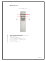
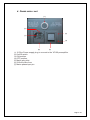
USER INSTRUCTIONS
VP100
Reference
HIGH END PREAMPLIFIER
VENTURE bvba
Hanendreef 23 – 2930 Brasschaat – Belgium
Tel : +32-36530732
Email : [email protected]
Fax : +32-36531349
Website : www.venture-audio.com
WARNING:
POTENTIAL SHOCK HAZARD!
This symbol is intended to alert the user of the presence of important operating
and maintenance (servicing) instructions in the literature accompanying the appliance
This symbol is intended to alert the user of the presence of non insulated
“dangerous voltage” within the product‘s enclosure that may be of sufficient magnitude to
constitute a risk of electric shock to persons
TO REDUCE THE RISK OF FIRE OR ELECTRIC SHOCK, DO NOT EXPOSE THIS
APPLIANCE TO RAIN OR MOISTURE.
This product uses high voltage. There are no operator serviceable parts inside.
Refer servicing to qualified personnel only. Observe all warnings and instructions
marked on the product. Use only a grounded outlet.
Do not install or use this product near water or in wet environment. Install the
product securely on a stable surface.
During operation the heat dissipaters and some other parts become hot: do not
touch.
Information:
Marking by the “CE” symbol indicates compliance of this device with the EMC
(Electromagnetic Compatibility) and LVD (Low Voltage Directive) standards of the
European Community.
Page 2 / 22
INDEX
I.
FOREWORD............................................................................................................................. 4
1.
2.
3.
CONGRATULATIONS!......................................................................................................................... 4
VENTURE AUDIO ................................................................................................................................ 4
VP100 REFERENCE ................................................................................................................................ 5
II.
SAFETY INSTRUCTIONS ........................................................................................................ 5
III.
OVERVIEW............................................................................................................................... 6
1.
2.
UNPACKING ............................................................................................................................................ 6
POSITIONING .......................................................................................................................................... 6
IV. DESCRIPTION OF APPLIANCE ELEMENTS ......................................................................... 7
1.
2.
3.
4.
V.
FRONT PANEL ......................................................................................................................................... 7
REAR PANEL ........................................................................................................................................... 8
REMOTE CONTROL ................................................................................................................................. 9
POWER SUPPLY UNIT ............................................................................................................................. 10
OPERATION INSTRUCTIONS............................................................................................... 11
1.
2.
3.
4.
5.
6.
7.
POWER SWITCH .................................................................................................................................... 11
INSTALLED CARDS ................................................................................................................................. 11
PHONO SECTION (RIAA MM/MC) ....................................................................................................... 12
OPERATIONS ........................................................................................................................................ 13
DISPLAYS DESCRIPTIONS ....................................................................................................................... 14
SECURITY ............................................................................................................................................. 16
CLEANING............................................................................................................................................. 17
VI. SPECIFICATIONS .................................................................................................................. 18
VII. WARRANTY ........................................................................................................................... 19
1.
2.
3.
DURATION ......................................................................................................................................... 19
CONDITIONS ..................................................................................................................................... 19
MISCELLANEOUS ............................................................................................................................. 19
VIII. QUESTIONS AND ANSWERS............................................................................................... 20
Page 3 / 22
I.
FOREWORD
1. CONGRATULATIONS!
You just have purchased the VP100 Reference preamplifier. VENTURE AUDIO first wants to
thank you for your trust.
The best components were selected for its realization, as an extreme care was provided
during its manufacturing. These attentions will permit to reach true musical quality heights.
VP100 Reference is the result of many years of studies and research, of much
experimentation, and of many careful listening sessions.
Used in conjunction with very high quality components – as the mono Class A amplifiers
V100A Reference, you can feel confident that all the recorded musical emotion will be played
back to you.
2. VENTURE AUDIO
Established in 1987, VENTURE started with the production of Car speakers followed by
Home High End speakers and cables.
In 1998 the first Tube Amplifier VENTURE REFERENCE ONE, a Single Ended mono
block amplifier with a special designed high power 300B tube family Venture 6300B, was
born, and after followed by its brother REFERENCE S-ONE, which is a stereo version of
the mono block. Both amplifiers were designed to produce a 25 watts output.
To fulfill the desire for Live Performance, a higher power is necessary and a solid state
100 watts Class A amplifier was designed together with the VP100 Reference preamplifier to
achieve that aim. The VP100 Reference preamplifier is designed as a complete set with the
V100A Reference power amplifier to meet the highest demand of today’s music lovers in their
music world of analogue and digital sources.
Both MC and MM phono stage were integrated in the system to achieve the highest quality
for the vinyl analogue play back.
Four single ended and four balanced line inputs with individually adjustable gain are
provided and this makes the system very unique.
No wish is left behind.
Page 4 / 22
3. VP100 REFERENCE
VENTURE AUDIO continues its research and now proposes its brand new amplifier,
VP100 Reference.
Its commuted resistors design and its fully Single-End discrete buffer allow obtaining a
really more natural restitution, through a transparence and dynamic never reached at
present times. Its multiple power-supplies are fully independent and are set in an external
cabinet, for a better magnetic isolation. All these enhancements participate in VP100
Reference deep analysis, distinctly felt from the very first notes played.
Its remote control, aside its comfortable ergonomics, will allow you to put your V100A
Reference mono Class A amplifier in Stand-By mode. This way, you will immediately reach
its highest level of musicality, with no warming up.
VP100 Reference amazing musicality will sublimate your imagination.
II.
SAFETY INSTRUCTIONS
Before operating your VENTURE AUDIO appliance, please read all
instructions and cautions carefully and completely.
1. ALWAYS disconnect your entire system from the AC mains before connecting or
disconnecting any cables, or when cleaning any component.
2. ALWAYS A three-conductor AC mains power cord which includes an earth ground
connection must be used. To prevent shock hazard, all three connections must be used.
3. Original AC mains power cord is recommended for use with this product.
4. NEVER use flammable or combustible chemicals for cleaning.
5. NEVER operate this product with removed cover.
6. NEVER wet the inside of this product with any kind of liquid.
7. NEVER pour or spill liquids directly onto this unit.
8. NEVER block air flow through ventilation slots or heat-sinks.
9. NEVER bypass any fuse.
10. NEVER replace any fuse with a value or type other than those specified (*).
11. NEVER attempt to repair this product: contact your retailer.
12. NEVER expose this product to extremely high or low temperatures.
13. ALWAYS unplug sensitive electronic equipment during lightning
Page 5 / 22
III.
OVERVIEW
1. UNPACKING
Your package contains:
) A VP100 Reference preamplifier.
) A Rc5 remote control, delivered with two Lr03 batteries (type AAA).
) An external power-supply unit
) A 12-pins power cord to plug between the preamplifier and the power-supply unit
) A mains power cord
) This user manual.
2. POSITIONING
Your VP100 Reference preamplifier must be installed in a place far from about 10cm from the
other appliances. This will guarantee the best signal-to-noise ratio. In the same manner,
please allow at least 50 cm between the power-supply unit and the preamplifier. The
plugged cord is 1m long.
You must keep about 10cm of free space above VP100 Reference chassis, to allow proper
heat dissipation.
Height and positioning within your furniture must be thought in a manner, where the angle
with the remote control will not exceed 40° in both horizontal and vertical axis.
Page 6 / 22
IV.
DESCRIPTION OF APPLIANCE ELEMENTS
1. FRONT PANEL
(1)
(2) (3)
(4)
c Selection and Set-Down (end of set-up) knob.
d Preamplifier offset security LED (default off)
e Digital display
f Volume and Set-Up (begin of set-up) knob.
Page 7 / 22
2. REAR PANEL
(21)
(10) (9)
(1)
(2)
(3)
(4)
(5)
(6)
(7)
(8)
(9)
(10)
(22)
(8)
(7)
(23)
(6)
(5)
(24)
(4)
RIGHT CHANNEL
RCA Right output
XLR Right output
RCA 1 Right Input
XLR 2 Right Input
RCA 3 Right Input
XLR 4 Right Input
RCA 5 Right Input
XLR 6 Right Input
RCA 7 Right Input
XLR 8 Right Input
(3)
(25)
(2)
(1)
(26)
(11) (12) (13) (14) (15) (16) (17) (18) (19) (20)
(11)
(12)
(13)
(14)
(15)
(16)
(17)
(18)
(19)
(20)
(21)
(22)
(23)
(24)
(25)
(26)
LEFT CHANNEL
RCA Left output
XLR Left output
RCA 1 Left Input
XLR 2 Left Input
RCA 3 Left Input
XLR 4 Left Input
RCA 5 Left Input
XLR 6 Left Input
RCA 7 Left Input
XLR 8 Left Input
MC phono Right input
MM phono Right input
MM phono Left input
MC phono Left input
BNC Stand-By mode output
Power-supply cord plug (10-pins)
Page 8 / 22
3. REMOTE CONTROL
Infrared LED emitter
(1)
(2)
(3)
(4)
(5)
(6)
(7)
(8)
(1)
(5)
(2)
(6)
(3)
(7)
(4)
(8)
Switch on/off the digital display.
Mutes the sound, or back to previous volume.
Selects inputs (-).
Lowers sound volume (-).
Sets the amplifiers in Stand-By mode
Wakes the amplifiers up (Stand-by off)
Selects inputs (+).
Rises sound volume (+).
Page 9 / 22
4. POWER SUPPLY UNIT
(1)
(5)
(4)
(7)
(3)
(6)
(1)
(2)
(3)
(4)
(5)
(6)
(7)
(2)
10-Pins Power-supply plug to connect to the VP100 preamplifier
On/Off switch
ON position.
OFF position.
Mains plug inlet.
500mA mains fuse
Mains phase input pin.
Page 10 / 22
V.
OPERATION INSTRUCTIONS
1. POWER SWITCH
After having connected the different inputs to the corresponding appliances (CD player,
tape, tuner...) and the outputs to the dedicated appliances (amplifiers, crossovers…), the
VP100 Reference preamplifier can be switched on using the power switch located on the rear
panel.
It is advised not to switch off the VP100 Reference, to fully and instantly benefit from its
maximum musical quality. However, if you are meant to keep away for a long time (as for
holidays for instance), or in the case of any storm risk, it is considered safe to switch the
appliance off, with the rest of your Hi-Fi elements.
2.
INSTALLED CARDS
The VP100 Reference preamplifier is provided with three cards:
) The motherboard processes the high level input signals and the main amplifier
(left/right) outputs
) The phono (RIAA) card is used as vinyl turntable preamplifier. There are 4 RCA
input plugs, to handle the MM (2 RCA) and MC (2 RCA) formats.
Page 11 / 22
3. PHONO SECTION (RIAA MM/MC)
The VP100 has an adaptive (active) input load. There is no need for users to adjust the
resistance input according to the cell they use (as they used to do thanks to MC input
resistors matrix). Just plug your turntable to the right RCA (be it MM or MC depending on
your appliance) and enjoy the music. This is safe, this is easy, and this will sound perfectly
to the taste of your cell.
For the MM input, there is set of 4 capacitors within the preamplifier, changeable by
switches: No capacitor (default), 47pF, 100pF, 220pF, 470pF (any combination possible).
Just open the case and adjust the switch with a little screwdriver, according to your cell
specifications. If you do not have any, make some tests and pick the best sounding option.
Please refer to the drawing below.
You must not set any capacitor if you use the MC input.
Page 12 / 22
4. OPERATIONS
Stand-By mode is accessible from the remote control. It allows reducing dramatically the
energy consumption of the appliance. Once awoken (disabling the stand-by mode), the
preamplifier will provide its optimum musical quality after only 15 minutes, whereas the first
operation will require more than 4 hours of warm-up (as will require any main switch-on) to
reach this same level.
VP100 Reference offers 10 inputs (4 unbalanced “RCA”, and 4 balanced “XLR”, 1 Phono MM,
1 Phono MC). At start-up, it initializes itself to the RCA1 input and the -66 db volume level
(max attenuation). Using the remote control, it is then possible to toggle the input or to
adjust the volume.
Mute function from remote control permits to lower instantly the volume to its minimum
(being -90 dB). A new stroke on the Mute key will bring the volume level back to its
previous state.
Display function from the remote control permits to switch the digital display on or off.
Set-up is accessed through a light push on the “Volume” knob. It allows to tune some
parameters at initial set-up of your preamplifier (or Hi-Fi system), as the channel balance
between left & right, crossover frequency, the accentuation (bass boost) and the phase.
First option concerns the pink noise, which is used to emit a neutral noise on all speakers.
This allows to finely tuning the channel balance without requiring the use of one of the 8
external sources. Pink noise is activated by entering the setup. After enabling it, please
adjust the generated volume level using the remote control or the front volume knob.
The following step of the set-up proposes the balance between the different channels: 2 in
stereo mode (standard). The inter-channels balance is limited to a 9dB maximum.
The last option of the set-up allows teaching new remote control codes to the preamplifier.
This function is generally let unused.
Push lightly on “Selection” knob to exit the set-up program. All parameters are then stored
within the preamplifier.
Page 13 / 22
5. DISPLAYS DESCRIPTIONS
Standard display at start-up
After start-up, the display shows the volume (attenuation level)
of -66dB, and the first input is activated (RCA)
The volume can be modified through remote control or the
dedicated front knob, from –65dB (low volume) to 0dB (loud).
By using the remote control or selection knob, the different
inputs can be selected: RCA1, XLR2, RCA3, XLR4, RCA5,
XLR6, RCA7, XLR8, MM and MC.
MM input is selected as the 9th input of the preamplifier
(after XLR8)
MC input is selected as the 10th input of the preamplifier
(after MM)
By turning the Selection knob right, or using the remote control,
we process to the pink noise generator volume adjustment. It
shows initially the previous general volume level (before set-up).
Still turning right the Selection knob, we process to the channels
balance. Balance is limited to a 9dB difference between
channels. We start with left channel.
Still turning right the Selection knob, we process to right
channel.
By turning right the Selection knob, we process to the subwoofer
phase selection, defaulted to 0°.
By turning right the Volume knob, the phase is increased by
steps of 10° up to 180° (maximum).
Page 14 / 22
By turning left the Volume knob, the phase is decreased by
steps of 10° down to -180° (minimum).
Last in the set-up program, we can teach the preamplifier some
new remote control codes. This functionality is only to be used
when using a new remote control.
This option is defaulted to OFF (disabled). Turn the volume
knob right to enable it. Turning left sets it back to OFF.
LEARN RC5
ERROR
To use this functionality, select ON then exit the set-up. The
screen displays LEARN RC5 ERROR. Now press any key from
the remote control. The operation is complete. The preamplifier
displays back its welcome screen.
[EXIT]
Push lightly on the Selection knob to exit at any step from the
set-up program. Parameters are now stored within the
preamplifier.
In normal mode (outside set-up) the stand-by mode can be
activated from the remote control. It will put the mono amplifier
blocks (V100A Reference) in stand-by mode (to lower the current
consumption when the equipments are not used). See Q&R.
Page 15 / 22
6. SECURITY
VENTURE AUDIO appliances are designed to operate in a perfect reliable and durable
condition. This operation can however be influenced by external events. Some of them will
require the action of the inner VP100 Reference security system.
This security system aims at protecting the appliance from any over-voltage, for instance,
as they also act to protect the whole Hi-Fi elements under the preamplifier
« responsibility ». Speakers for instance are this way protected from DC offset (at input or
output of the preamplifier), often issued by source components such as CD players; once
amplified, they can cause irreversible damages.
An activated security (front red LED is ON) will block the preamplifier operation until the
problem or cause is fixed. In case of mains over-voltage for instance, the fuse within the
external power-supply unit may have been blown. Please, only replace the fuse with the
same one, as described here-under. In case of difficulties in finding these fuses, please
don’t hesitate to contact us.
For more information on the reasons of security system calls, please refer to the
associated table within the « questions and answers » chapter.
Last, it is important to underline that these are exceptional cases, which never occur under
normal conditions and good quality Hi-Fi elements (this implies that normal conditions do
not call the security system and consequently do not require fuse changes).
External:
A 500 mA (slow-blow) fuse is used on the mains socket base, within the external powersupply unit (for 230V)
A 1A (slow-blow) fast fuse is used on the mains socket base, within the external powersupply unit (for 100-120V)
Internal:
No fuse here, but a relay-based security system.
Page 16 / 22
7. CLEANING
VP100 Reference preamplifier was designed to operate perfectly with no specific setting or
maintenance for a large number of years.
In case of dust removal, plainly process using a clean dry rag. In case of a dirty mark, DO
NOT uses any detergent or solvent, but uses a clean wet rag.
Caution:
NEVER clean any appliance while in operation.
Page 17 / 22
VI.
SPECIFICATIONS
Main section:
Type:
Preamplifier
Volume:
-66dB to 0dB
Unbalanced Gain:
0dB
Balanced Gain:
6dB
Harmonics Distorsion:
<0.01% / 600 Ohms / 2Volts
Noise:
<2.8µV (Typ.1,9µV)
Signal-to-Noise ratio:
> 120dB
Offset:
<0.1mV
Max input level:
4.5Veff / 600 Ohms
Inputs:
4 XLR inputs
4 RCA inputs + 2 Phono RCA (MM/MC)
Output 1: XLR
Max level: 9Veff / 600 Ohms
Output 2: RCA
Max level: 4.5Veff / 600 Ohms
Inter-cards balance:
+/- 9dB ; 2 channels
Dimensions:
483 x 110 x 330 mm
Weight:
9 Kg / 19.8 lbs
Phono / RIAA section:
MM:
MC: (for 100 Ohms load)
Sensitivity (for 0.1V Output) = 1.8 mV
Gain = 30 dB
Signal-to-Noise ratio = > 88 dB
Signal-to-Noise ratio = > 95 dB
THD (1Volt/1KHz) = < 0.005 %
THD (0.1Volt/1KHz) = < 0.05 %
Vout max = 1 Volt
Vout max = 1 Volt
Offset = < 1mV
Offset: <0.5mV
Page 18 / 22
VII. WARRANTY
1. DURATION
VENTURE AUDIO products are warranted to be free of defects if used under normal
conditions for a period of two (2) years from the date of purchase.
2. CONDITIONS
This warranty is subject to the following conditions and limitations. The warranty is void
and inapplicable if the product has been used or handled other than in accordance with the
instructions in the owner’s manual, abused or misused, damaged by accident or neglect or
in being transported, or if the defect is due to the product being repaired or tampered with
or modified by anyone other than VENTURE AUDIO or an authorized repair center, or in
case of removal, defacing or falsifying of the serial numbers.
3. MISCELLANEOUS
Any implied warranties relating to the above product shall be limited to the duration of this
warranty. The warranty does not extend to any incidental or consequential costs or
damages to the purchaser.
Page 19 / 22
VIII. QUESTIONS AND ANSWERS
What difference is there between VENTURE and standard stand-by mode?
VENTURE stand-by mode does not switch off fully the appliance. Only the power
stages are shut-off. They are the main current consumers. The heart of the amplifier
stays warm and operational. This allows getting the full musical quality back in about
10 to 15 minutes after waking the appliance back up. A standard switch-on of the
appliance requires about 8 hours getting that same level back. The current
consumption is divided by about 10 in stand-by mode. VENTURE however
recommends switching the appliance fully off when leaving it unused for longer
periods (holidays…).
Can the provided mains cable be changed?
The provided mains cable answers to standard norms. It can however be replaced
by a high fidelity mains cable, if it answers to the same norms. A very sensitive
musical gain can be heard, depending on the chosen cable. VENTURE AUDIO can
help you in making this choice if preferable.
Caution: When changing this cable, please follow the polarity conditions of your
country. Phase location is different for instance between US and French norms.
While it would not prevent the appliance to operate, a sensitive loss could be heard
(sound laid back).
Is there any specific order to switch my Hi-Fi elements on?
Absolutely. While it is not specific to VENTURE products. Always switch on the
source elements first: they sometimes emit a spark at switch on, and this must not be
amplified and pushed to the speakers. Then follow down the elements. We provide
here under an example of a switch-on chain: CD player, decoder (DAC), preamplifier
active crossovers, and then amplifiers.
To switch off, please follow the reverse order.
Is there any specific order to switch my Hi-Fi elements off?
Absolutely. While it is not specific to VENTURE products. Always switch off the
source elements last: they sometimes emit a spark at switch off, and this must not be
amplified and pushed to the speakers. Start from the bottom and then follow up to
the source elements. We provide here under an example of a switch-off chain:
amplifiers, active crossovers, preamplifier, decoder (DAC), and CD player.
To switch on, please follow the reverse order.
Heat dissipaters are very hot? Is it dangerous?
VENTURE products aim at get the maximum from all internal components. Heat
dissipaters are pushed to their optimum to guarantee a maximal class A operation,
as it means excellence in musical quality. However, VENTURE products follow
security norms and do not push the heat beyond legal limits. There is consequently
no excessive heat: contact is hot, but do not get warmer with time (once appliance is
considered warm). Also, heat regulators are used to prevent any thermal runaway
and this way protect the appliance. This inevitably limits the level of class A at high
volumes.
Page 20 / 22
What specific handling instructions are there for VENTURE appliances?
See “Operation instructions”.
Please note however, that it is always safe to switch off and unplug all mains cables
before handling any cable from the system, being interconnects mains, speakers, or
digital. This caution is not specific to VENTURE products.
Also, please allow 30 seconds (mainly to the power appliances) before unplugging
the cables. This will let the capacitors to empty themselves smoothly (no spark
effect).
These cautions are not simply an instruction manual chapter. Many problems and
failures can really this easy be avoided (ground short-cuts, sparks on appliances…).
The appliance does not switch on. No sound comes out. What can I do?
This is a vague question. We can only provide some clues to help you check the
main issues. Please check this list before contacting us.
1) Check your house mains alimentation
2) Check that your mains cable is connected to a wall-outlet (AC alimented)
3) Check that your mains cable is connected to the VP100 Reference inlet
4) Check that your appliance voltage is compliant with your domestic one
5) Check that the rear switch is set to ON
6) Check that your amplifiers are ON
7) Check that the preamplifier/amplifier are not in stand-by mode
8) Check that the remote control is operating (with right AAA batteries) to have
your appliance waken up from the stand-by mode (if it was)
9) Check that source elements are ON (CD player…)
10) Check that source elements are connected to an INPUT plug from your
preamplifier.
11) Check that you selected that ACTIVE input
12) Check that your preamplifier and amplifiers are rightly connected (eventually
through active crossovers)
13) Check that your active crossovers (if any) are ON
14) Check that your speakers are connected to the amplifier. This check concerns
every pair if you use multi-wiring. Also check the cables on your speaker and
crossover ports.
15) Check that the appliance is not OFF due to the security-system. Unplug all, and
switch it back on once you have changed the faulty fuse.
Page 21 / 22
What are the security system-call causes?
See security chapter for more explanations.
Cause
Over-tension
(mains provider)
External
fuse
Internal
relay
X
Comment / solution
Rare. Change the fuse. Unplug and
switch back on.
DC offset
X
(front
LED :
Red/ON)
Generally comes out source elements
such as CD players. Unplug all. Switch
the appliance back on. It must operate
perfectly alone. In that case, have your
faulty element fixed/repaired accordingly.
Appliance internal
failure (internal DC
Offset)
X
The appliance alone does not operate.
(front
Contact us
LED :
Red/ON)
How to diagnose the security system-call cause before plugging back all my Hi-Fi
system?
See above.
Any other question?
Do not hesitate to contact us: we will be happy to provide you an accurate and
custom answer.
Page 22 / 22