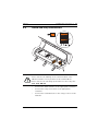
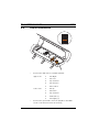
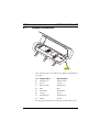
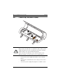
1
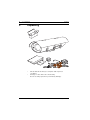
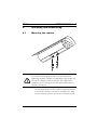
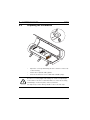
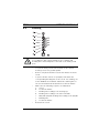
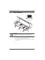
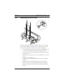
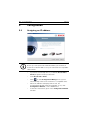
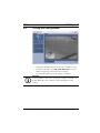
VOT-320
VOT-320V0xxL | VOT-320V0xxH
en
Quick Installation Guide
VOT-320
Table of Contents | en
3
Table of Contents
1
General information
4
2
Parts included
5
3
Unpacking
6
4
Installing and connecting
7
4.1
Mounting the camera
7
4.2
Preparing the installation
8
4.3
Earthing
9
4.4
Serial connection
10
4.5
Alarm and relay connections
11
4.6
Pan/tilt connection
12
4.7
Network connection
13
4.8
Connecting the power supply
14
4.9
Adjusting the WFOV lens
15
5
Configuration
16
5.1
Assigning an IP address
16
5.2
Testing the configuration
17
Bosch Sicherheitssysteme GmbH
Quick Installation Guide
F.01U.266.039 | V5.5 | 2012.03
4
1
en | General information
VOT-320
General information
This Quick Installation Guide applies to all variants of the
VOT-320.
WARNING!
For compliance with safety regulations, the earthing and
bonding wires must always be connected to the main ground
post.
Only operate the VOT-320 in combination with a SELV power
supply unit.
CAUTION!
You should always make yourself familiar with the required
safety measures in the relevant chapter of the Installation and
Operating Manual (see product CD). This contains important
information on installation and operation.
This Quick Installation Guide only describes the basic
procedure for installing a VOT-320 and cannot replace the
complete manual.
For further detailed information, please see the extensive
online Help for the VOT-320.
This Quick Installation Guide, the Installation and Operating
Manual and the current firmware package are available in other
languages at www.boschsecurity.com.
F.01U.266.039 | V5.5 | 2012.03
Quick Installation Guide
Bosch Sicherheitssysteme GmbH
VOT-320
2
Parts included | en
5
Parts included
–
1 VOT-320 thermal IP camera
–
5 terminal blocks
–
1 focussing tool (to be used with WFOV lenses)
–
1 RJ45 plug
–
10 screws, 2 washers and 2 lock washers to
fasten the housing
–
3 tamper resistant torx screws to lock the latches
–
1 torx wrench
–
4 cable glands
–
3 nuts for cable glands
–
3 plugs for unused cable glands
–
1 Quick Installation Guide
–
1 product CD
Bosch Sicherheitssysteme GmbH
Quick Installation Guide
F.01U.266.039 | V5.5 | 2012.03
6
3
en | Unpacking
VOT-320
Unpacking
–
Check that the delivery is complete and in perfect
condition.
–
Arrange for the unit to be checked by
Bosch Security Systems if you find any damage.
F.01U.266.039 | V5.5 | 2012.03
Quick Installation Guide
Bosch Sicherheitssysteme GmbH
VOT-320
Installing and connecting | en
4
Installing and connecting
4.1
Mounting the camera
7
CAUTION!
The camera must be properly and securely mounted to a
supporting structure capable of sustaining the unit weight. Use
care when selecting mounts or pan/tilts (not supplied) for
installation; the mounting surface and unit's weight must be
carefully considered.
–
Use two appropriate screws, washers and spring washers
to mount the camera to a mount or a pan/tilt. The spring
washers must be used for the screws to thread properly.
Bosch Sicherheitssysteme GmbH
Quick Installation Guide
F.01U.266.039 | V5.5 | 2012.03
8
en | Installing and connecting
4.2
VOT-320
Preparing the installation
–
Open the cover by unlatching the three latches on the side
of the housing.
–
Fasten the required cable glands.
–
Close holes that are not needed with suitable plugs.
CAUTION!
Be sure to securely tighten all fittings to ensure a liquid-tight
seal. Failure to do this could allow water to enter the housing
and damage electronic parts, camera, and lens.
Use drip loops on the wiring outside of the rear end caps.
F.01U.266.039 | V5.5 | 2012.03
Quick Installation Guide
Bosch Sicherheitssysteme GmbH
VOT-320
4.3
Installing and connecting | en
9
Earthing
CAUTION!
For compliance with safety regulations, the earthing and
bonding wires must always be connected to the main ground
post.
–
Loosen the fixing screw on the bottom of the camera
housing next to the ground symbol.
–
Remove only the bottommost tooth lock washer from the
screw.
–
If you mount the camera on a pan/tilt, first attach the
corresponding bonding wire to the screw. For earthing, use
a wire AWG 18 size minimum. Attach the earthing wire to
the screw. Reattach the bottommost tooth lock washer.
–
–
Make sure the following sequence is maintained:
a.
Screw
b.
Tooth lock washer
c.
Bonding wire leading to the housing top
d.
Bonding wire leading to the camera module
e.
Only with pan/tilt: Bonding wire leading to the pan/tilt
f.
Earthing wire
g.
Tooth lock washer
Refasten the screw.
Bosch Sicherheitssysteme GmbH
Quick Installation Guide
F.01U.266.039 | V5.5 | 2012.03
10
en | Installing and connecting
4.4
VOT-320
Serial connection
CAUTION!
Please observe the labeling on the camera module of the
VOT-320 and the correct position for the terminal block.
–
If you require a serial connection to the VOT-320, connect
the relevant cables to the terminal block.
–
Connect the terminal block to the upper orange socket on
the VOT-320.
F.01U.266.039 | V5.5 | 2012.03
Quick Installation Guide
Bosch Sicherheitssysteme GmbH
VOT-320
4.5
Installing and connecting | en
11
Alarm and relay connections
CAUTION!
Please observe the labeling on the camera module of the
VOT-320 and the correct position for the terminal block.
Please observe the following specifications for the relay outs:
max. 30 V, 200 mA
–
Connect the alarm switches to the appropriate terminals.
–
Connect the relay connections to the appropriate
terminals.
–
Connect the terminal blocks to the orange sockets on the
VOT-320.
Bosch Sicherheitssysteme GmbH
Quick Installation Guide
F.01U.266.039 | V5.5 | 2012.03
12
en | Installing and connecting
4.6
VOT-320
Pan/tilt connection
–
Connect the VOT-320 to a suitable pan/tilt:
Upper row:
Lower row:
–
1
Pan Right
2
Pan Left
3
P/T Common
4
Pan Position
5
Tilt Position
1
Tilt Up
2
Tilt Down
3
P/T Common
4
PP Return (–)
5
PP Supply (+)
Connect the ground wire from the pan/tilt to the GND
screw on the bottom inside the housing.
F.01U.266.039 | V5.5 | 2012.03
Quick Installation Guide
Bosch Sicherheitssysteme GmbH
VOT-320
4.7
Installing and connecting | en
13
Network connection
–
First crimp the wires according to the EIA/TIA standard you
are using:
–
Pin
EIA/TIA-568-A
EIA/TIA-568-B
1
white/green
white/orange
2
green
orange
3
white/orange
white/green
4
blue
blue
5
white/blue
white/blue
6
orange
green
7
white/brown
white/brown
8
brown
brown
Connect the VOT-320 to the network via the RJ45 socket.
Bosch Sicherheitssysteme GmbH
Quick Installation Guide
F.01U.266.039 | V5.5 | 2012.03
14
en | Installing and connecting
4.8
VOT-320
Connecting the power supply
CAUTION!
Only operate the VOT-320 in combination with a SELV power
supply unit that meets the following specifications: 24 VAC
output voltage, min. 33.6 VA without pan/tilt.
Please observe the labeling on the camera module of the
VOT-320 and the correct position for the terminal block.
–
Connect the power supply unit cables to the terminal
block.
–
Connect the terminal block to the orange socket on the
VOT-320.
–
Insert the power supply unit plug into a suitable socket.
F.01U.266.039 | V5.5 | 2012.03
Quick Installation Guide
Bosch Sicherheitssysteme GmbH
VOT-320
4.9
Installing and connecting | en
15
Adjusting the WFOV lens
Cameras with 9 mm, 13 mm, and 19 mm lenses cover a wide
field of view (WFOV). You may need to adjust the focus. All
other lenses are preset and do not need to be adjusted.
–
To check the image, connect a monitor to the BNC socket.
–
Loosen the four fixing screws of the camera module.
–
Lift the camera module and slide it backwards in order to
–
Attach the focussing tool to the lens and turn it to set the
–
Remove the focussing tool.
–
Lift the camera module and slide it back to the original
–
Refasten the four screws and disconnect the monitor.
–
Close the cover of the housing, and secure the latches
reach the lens.
focus.
position.
using the tamper resistant screws and the provided torx
wrench.
Bosch Sicherheitssysteme GmbH
Quick Installation Guide
F.01U.266.039 | V5.5 | 2012.03
16
en | Configuration
VOT-320
5
Configuration
5.1
Assigning an IP address
NOTICE!
Before you can operate the VOT-320 within your network, it
must have a valid IP address for your network and a compatible
subnet mask.
–
If you have not already done so, install the Bosch Video
Client program from the product CD.
–
Start Bosch Video Client.
–
Click
to start Configuration Manager. The system
automatically searches the network for compatible units.
–
When the VOT-320 is displayed in the list, the
Configuration Wizard starts automatically. If not, click
Configuration Wizard... on the Tools menu.
–
Follow the instructions given in the Configuration Wizard
window.
F.01U.266.039 | V5.5 | 2012.03
Quick Installation Guide
Bosch Sicherheitssysteme GmbH
VOT-320
5.2
Configuration | en
17
Testing the configuration
–
Launch the Web browser and enter the IP address of the
module as the URL (e.g. http://192.168.0.116) to check
that it is properly connected to the network.
–
Use the links at the top of the pages to navigate.
NOTICE!
Set the graphics card of the computer to 16-bit or 32-bit color
depth. Otherwise the computer cannot display the video
images.
Bosch Sicherheitssysteme GmbH
Quick Installation Guide
F.01U.266.039 | V5.5 | 2012.03
18
en | Configuration
F.01U.266.039 | V5.5 | 2012.03
VOT-320
Quick Installation Guide
Bosch Sicherheitssysteme GmbH
Bosch Sicherheitssysteme GmbH
Robert-Bosch-Ring 5
85630 Grasbrunn
Germany
www.boschsecurity.com
© Bosch Sicherheitssysteme GmbH, 2012