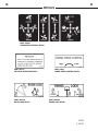
1
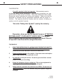
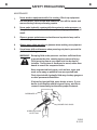
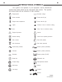
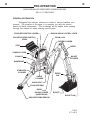
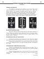
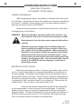
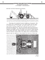
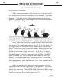
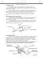
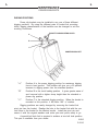
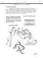
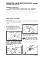
509 & 511 POWER BACKHOES
OPERATOR’S MANUAL
SERIAL NUMBER: ___________________
MODEL NUMBER: ___________________
800-922-2981 I www.paladinbrands.com
Manual Number: OM575
Part Number: 75475
Rev. 3
P.O. Box 266, Delhi, IA 52223-0266, United States of America
7483
8-5-05-4
TABLE OF CONTENTS
POWER BACKHOES
TO THE OWNER ............................................................................................... A
SAFETY PRECAUTIONS ................................................................................... B
Safety Alert Symbol
The Operator
The Vehicle
Working With The Backhoe
Transporting The Backhoe
Maintenance
INTERNATIONAL SYMBOLS ............................................................................ C
PRE-OPERATION ...............................................................................................D
General Information
Preparing the Vehicle
Bucket Options
Backhoe - Major Component Nomenclature
OPERATING INSTRUCTIONS .......................................................................... G
General Information
Controls
Before You Start Digging
Basic Digging Technique
Special Applications
Transporting
LUBRICATION ...................................................................................................H
General Information
Backhoe Lubrication Diagram
MAINTENANCE ................................................................................................. L
Every 8 Hours
Every 40 Hours
Control Valve
Replacing Bucket Tooth Points
Changing Buckets
Hose Routing
Cylinder Seal Replacement
BACKHOE STORAGE ....................................................................................... M
TROUBLE SHOOTING .......................................................................................N
BOLT TORQUE ................................................................................................. O
SPECIFICATIONS .............................................................................................. P
DECALS ............................................................................................................ Q
PRE-DELIVERY CHECK LIST............................................................................. R
LIMITED WARRANTY ....................................................................................... S
6893
3-8-96
A
TO THE OWNER
GENERAL COMMENTS
Congratulations on the purchase of your new backhoe! Your backhoe was
carefully designed and manufactured to give you many years of dependable
service. Your backhoe will require some minor maintenance (such as cleaning
and lubricating) to keep it in top working condition. Be sure to observe all maintenance procedures and safety precautions in this manual and on the safety
decals located on the backhoe and on any equipment on which the backhoe is
mounted.
ABOUT THIS MANUAL
Read this manual before using your backhoe. This manual has been designed
to help you to do a better, safer job. Read this manual carefully, and become familiar with the operating procedures before attempting to operate your new backhoe.
Remember, never let anyone operate this backhoe without them having
read and completely understand the "Safety Precautions" and "Operating
Instructions" section of this manual , or having them be fully trained by an
experienced, qualified person who has read and completely understands
the "Safety Precautions" and "Operating Instructions" (see sections B and
G respectively).
SERVICE
When servicing your backhoe, remember to use only original manufacturer replacement parts. Substitute parts may not meet the standards required for safe, dependable operation.
To facilitate parts ordering, record the model and serial number of your backhoe in
the space provided on this page. This information may be obtained from the
backhoe identification plate located on the left side of the backhoe console.
MODEL
SERIAL NO.
Your parts department needs this information to insure that you receive the
correct parts or attachments for your specific backhoe.
SAFETY ALERT SYMBOL
This is the "Safety Alert Symbol" used by this industry. This
symbol is used to warn of possible injury. Be sure to read all
warnings carefully. They are included for your safety and for
the safety of others working around you.
6741
6-16-98-2
A
B
B
SAFETY PRECAUTIONS
TAKE NOTE! THIS SAFETY ALERT SYMBOL FOUND THROUGHOUT THIS
MANUAL IS USED TO CALL YOUR ATTENTION TO INSTRUCTIONS INVOLVING YOUR PERSONAL SAFETY OR OTHERS. FAILURE TO FOLLOW
THESE INSTRUCTIONS CAN RESULT IN INJURY OR DEATH.
THIS SYMBOL MEANS:
ATTENTION!
BECOME ALERT!
YOUR SAFETY IS INVOLVED!
SIGNAL WORDS: Note the use of signal words DANGER, WARNING, and CAUTION with the safety messages. The appropriate signal word for each has been
selected using the following guidelines:
DANGER:
Indicates an imminently hazardous situation, which if not avoided, will
result in death or serious injury. This signal word is to be limited to the
most extreme situations, typically for machine components
which, for functional purposes, cannot be guarded.
WARNING: Indicates a potentially hazardous situation, which if not avoided, could
result in death or serious injury, and includes hazards that are
exposed when guards are removed. It may also be used to
alert against unsafe practices.
CAUTION:
Indicates a potentially hazardous situation, which if not avoided, may
result in minor or moderate injury. It may also be used to alert
against unsafe practices.
6621
5-18-95
B
B
SAFETY PRECAUTIONS
THE OPERATOR
A careful operator is the best operator. Most accidents can be
avoided by taking certain precautions. The following precautions are suggested here to help prevent accidents. Read and understand these safety
precautions before operating the vehicle and backhoe. Make sure that the
equipment is operated only by responsible individuals with the proper instruction. The operator should be familiar with the controls, all safety precautions and all potential hazards.
This is the "Safety Alert Symbol" used by this industry.
Remember, when you see this symbol it means: ATTENTION
BECOME ALERT! YOUR SAFETY IS INVOLVED! This symbol
with it's appropriate warnings are throughout this book. Be sure
all operator's read them before using the backhoe.
THE VEHICLE
1.
READ THE ENTIRE VEHICLE AND BACKHOE OPERATOR'S SAFETY
MANUALS BEFORE EVER ATTEMPTING TO USE THE VEHICLE. THIS
KNOWLEDGE IS NECESSARY FOR SAFE OPERATION.
2.
Follow all safety decals on the vehicle. Keep them clean and replace
them if they become worn and hard to read.
3.
Pay attention to the job at hand. Do not let your mind lose concentration on what you are doing.
4.
Know the limitations of your equipment. Do not use equipment for
anything other than what it was originally designed.
5.
Always use the seat belt if the vehicle has a ROPS. Do not use it if
there is no ROPS. Check the seat belt daily and replace if frayed or
damaged.
6780
1-15-96
B
B
SAFETY PRECAUTIONS
6.
Do not take passengers on the vehicle or backhoe. There is no safe
place for a passenger.
7.
Use the handholds and step plates when getting on/off the vehicle.
Failure to do so could cause a fall.
8.
Inspect the vehicle before you try to operate the unit. Check for
needed maintenance or repairs and be sure to have them done before
using the equipment.
9.
Before performing maintenance. Set the parking brake, place the gear
shift lever in neutral, turn off the vehicle and remove the key.
10.
Wear appropriate clothing such as a hard hat, safety glasses, ear
plugs, etc. Do not wear loose fitting clothing, it could get caught on
the equipment.
11.
Never operate or transport unit with covers or shields removed.
12.
Never leave unit running unattended. Follow vehicle operator's
manual for correct operation.
13.
Reduce speed when driving over rough terrain, on a slope, or turning,
to avoid overturning the vehicle.
14.
Do not smoke when refueling the vehicle. Allow room in the gas tank
for expansion. Wipe up any spilled fuel. Secure cap tightly when
done.
15.
Do not modify the backhoe or it's mounting frames in any way unless
authorized by ATI Incorporated to do so. Unauthorized modifications
could result in equipment damage and/or personal injury.
16.
Look before backing.
WORKING WITH THE BACKHOE
1.
Never operate backhoe by standing up on, or beside the machine.
Operate only from the backhoe seat.
2.
Do not lift or carry people on the backhoe, they could fall and be
crushed.
3.
Do not adjust relief valve setting. This valve is factory set and should
be adjusted only by a qualified service person. Incorrect valve setting
could result in equipment damage and/or personal injury.
4.
Check your work area. Avoid hitting overhead electrical wires, underground cables and pipes, fence post, gas lines, etc.
6781
1-15-96
B
B
SAFETY PRECAUTIONS
5.
Block off work area from all bystanders, livestock, etc. Allow plenty of
room for backhoe reach and swing.
6.
When operating on slopes, dig with the backhoe uphill, and avoid full
reach and swinging the backhoe bucket to the downhill side. Tipping
could result.
7.
Operate backhoe only from backhoe seat.
8.
Use your backhoe only for digging. Do not use it to pull things, as a
battering ram, or attach ropes, chains, etc., to the unit.
9.
Never work under raised stabilizers or a raised bucket.
10.
Lower stabilizers and bucket when removing backhoe. This will
increase the stability of the unit.
11.
Do not dig close to stabilizers, the ground could collapse from under
the backhoe
12.
Do not lift loads in excess of backhoe capacity.
13.
Always lower the backhoe bucket and stabilizers to the ground, shut
off engine, remove key, and apply the parking brake before leaving
the unit unattended.
TRANSPORTING THE BACKHOE
1.
Be sure to engage the boom lock and swing lock before transporting
backhoe. Failure to do so could cause an unstable traveling
condition.
2.
Allow for height of backhoe when transporting backhoe so as not to
catch unit on low overhangs or wires.
3.
When driving on public roads use safety lights, reflectors, Slow
Moving Vehicle signs, etc., to prevent accidents. Check with local
governments for regulations that may affect you.
4.
Do not drive close to ditches, excavations, etc., cave in could result.
Drive slow over rough terrain.
5898
9-2-92
B
B
SAFETY PRECAUTIONS
MAINTENANCE
1.
Never work on equipment while it is running. Block up equipment,
set hand brake, lower bucket and stabilizers, turn off the tractor and
remove the key before performing repairs.
2.
Never make hydraulic repairs while the system is under pressure, or
the cylinders are under load. Serious personal injury or death could
result.
3.
Observe proper maintenance schedules and repairs to keep unit in
safe working order.
4.
Always wear safety goggles or glasses when working on equipment.
5.
Use a brass drift and hammer when pressing out pins to prevent the
pin from shattering.
WARNING! Escaping fluid under pressure can have sufficient force
to penetrate the skin, causing serious personal injury.
Fluid escaping from a very small hole can be almost
invisible. Use a piece of cardboard or wood, rather than
hands to search for suspected leaks.
Keep unprotected body parts, such as face, eyes, and
arms as far away as possible from a suspected leak.
Flesh injected with hydraulic fluid may develop gangrene
or other permanent disabilities.
If injured by injected fluid, see a doctor at once. If your
doctor is not familiar with this type of injury, ask him to
research immediately to determine proper treatment.
CARDBOARD
MAGNIFYING GLASS
HYDRAULIC HOSE
OR FITTING
5899
9-2-92
C
C
INTERNATIONAL SYMBOLS
As a guide to the operation of your equipment, various international
symbols have been utilized on the instruments and controls. The symbols
are shown below with an indication of their meaning.
Engine speed
Alternator charge
Hours recorded
Power take-off (on)
Engine water temperature
Power take-off (off)
Lights
"Tortoise," slow or minimum setting
Horn
"Hare," fast or maximum setting
Engine oil pressure
Caution
Hazard warning
Control lever operating direction
Axle connect
Rock shaft (raised)
Axle disconnect
Rock shaft (lowered)
Continuously variable
Remote cylinder (extended)
Increase
Remote cylinder (retracted)
Decrease
Remote cylinder (FLOAT)
Diesel fuel
Differential lock
Creeper range
Read operators manual
High range
Neutral
Low range
Forward
Reverse
3869
4-14-94-2
D
D
PRE-OPERATION
509 & 511 POWER BACKHOE
GENERAL INFORMATION
The purpose of this manual is to assist in setting up, operating and
maintaining your backhoe. Read it carefully. It furnishes information and
instructions that will help you achieve years of dependable performance.
Right and left, when referred to in this manual, are determined from
the operator's control position when facing the backhoe.
The illustrations and data used in this manual were current (according
to the information available to us) at the time of printing, however, we
reserve the right to redesign and change the backhoes as may be necessary
without notification.
PREPARING THE VEHICLE
WARNING! Never let anyone operate this tractor and backhoe without
understanding all of the "Safety Precautions" and "Operating
Instructions" sections of this manual. (See Section B and G
respectively.) Always choose hard, level ground to park the
tractor on and set the brake so that the tractor cannot roll.
BACKHOE
Basic backhoes are shipped complete with bucket. However, several
bucket options are available for the backhoe. Refer to the table for proper
identification of backhoe bucket options.
SEVERE DUTY POWER DIG
BUCKET ASSEMBLIES
12"
16"
18"
20"
24"
#85012
#85016
#85018
#85020
#85024
Additional buckets available upon request.
7484
6-7-99-2
D
D
PRE-OPERATION
BACKHOE MAJOR COMPONENT NOMENCLATURE
509 & 511 BACKHOE
GENERAL INFORMATION
Throughout this manual, reference is made to various backhoe components. The purpose of this page is to acquaint you with the various
names of these components. This knowledge will be helpful when reading
through this manual or when ordering service parts.
STABILIZER CONTROL LEVERS
BUCKET & DIPPER CONTROL
LEVER
BOOM & SWING CONTROL LEVER
BOOM LOCK
DIPPER CYLINDER
SEAT
DIPPER
CONSOLE COVER
BUCKET
CYLINDER
CONSOLE
MAINFRAME
STABILIZER
CYLINDER
SWING
CYLINDER
DIPPER
LINK
SWING POST
STABILIZER ARM
BOOM
BOOM CYLINDER
(INSIDE BOOM)
BUCKET
BUCKET LINK
GROUSER STABILIZER PAD
7485
6-7-99-2
G
OPERATING INSTRUCTIONS
CONTROLS
GENERAL INFORMATION
Your backhoe is operated by four different control levers. Two are for
stabilizer operation and the other two operate the swing, boom, dipper, and
bucket functions. The information contained below will help you become
familiar with the operation of each control lever. Read the safety precautions (Section B) of this manual before attempting to use the backhoe.
Remember, right and left when referred to on this page are determined by
the operator’s position seated at the backhoe controls facing the bucket.
BOOM/SWING
CONTROL LEVER
LEFT
RIGHT
STABILIZERS
DIPPER/BUCKET
CONTROL LEVER
BACKHOE STABILIZER LEVERS
Moving the stabilizer lever(s) forward will bring the backhoe stabilizer (s)
"Down". Moving the stabilizer lever(s) rearward will raise the backhoe stabilizers "Up". Both stabilizers are required to be down for proper stability of the
backhoe when in operation.
BOOM/SWING LEVER (LEFT HAND LEVER)
Pushing the boom/swing lever forward will "Lower" the boom dipstick
and bucket. Pulling the lever rearward will "Lift" the boom, dipstick, and bucket.
Pushing the boom/swing lever to the left will swing the boom and bucket
to the "Left". Pushing the lever to the right will swing the boom, and bucket to
the "Right".
DIPPER/BUCKET LEVER (RIGHT HAND LEVER)
Pushing the dipper/bucket lever forward will move the dipper "Out" or
away from the operator. Pulling the lever rearward will move (crowd) the dipper
"In" or toward the operator.
Pushing the dipper/bucket lever to the left will "Fill" or curl the bucket
(move inward). Pushing the lever to the right will "Dump" the bucket (move
outward).
3958
5-16-94-2
G
G
G
OPERATING INSTRUCTIONS
OPERATING TECHNIQUES
ATTACHMENT TYPE BACKHOES
GENERAL INFORMATION
When operating the backhoe, smoothness of technique should be strived
for at all times. Smoothness will come with experience and practice at feathering
the controls. Establish a flowing digging cycle to increase operator efficiency
and save unnecessary wear on the machine.
Observe the following points to obtain the best results and to fully utilize
the digging force of the backhoe.
WARNING! Operate the backhoe only when seated at the controls. Any
other method could result in serious personal injury or death.
Never attempt to drive the tractor when seated at the backhoe
controls.
Check the prospective digging area for hidden utility lines
before operating the backhoe or when in doubt of their location, contact the local utility companies. When operating the
backhoe in an area where utilities are expected to be present,
throttle the backhoe down and proceed with caution. If you
feel the backhoe bucket made contact with anything out of the
ordinary, stop digging at once. Have the obstruction checked
by hand. If a utility line has been damaged, contact the affected utility at once.
BEFORE YOU START DIGGING
Before any excavating is started, it is always a good idea to plan out the
job first. Various things need to be considered and taken into account prior to
the actual digging. The operator should inspect the job site and take notice of
any potential hazards in the area. He should have a complete understanding of
the tasks he is expected to perform. Figure out what will be done with the spoil
(excavated soil), will it be used to backfill or be trucked out? What are the soil
conditions like? Will you have to work around others? Etc.
Once you have become familiar with the job site and understand
the job requirements, it is time to set up for the actual digging. Position the
backhoe in such a way as to minimize repositioning the unit and to maximize
digging efficiency. Consider the placement of spoil and position the backhoe to
be able to dig the maximum amount of soil, accurately, while leaving enough
room for the spoil removed to be piled in the desired area.
6758
12-18-95
G
G
OPERATING INSTRUCTIONS
OPERATING TECHNIQUES
ATTACHMENT TYPE BACKHOES
BEFORE YOU START DIGGING (CONTINUED)
Once the unit is positioned, lower the stabilizers to the ground. The
tires should still be supporting most of the vehicle weight with the stabilizers relieving only part of the weight, and mainly acting to give the unit a
wider base for increased stability and to keep the unit from moving or
bouncing with backhoe use. The front end loader should also be lowered if
the unit is so equipped. The vehicle should at no time be supported by the
stabilizers and loader with any of its wheels off the ground. Severe damage
to the vehicle could result. When operating the unit on a delicate surface
(such as concrete, or stone work) or on sandy, loose, or soft ground place
plywood under the stabilizers to help distribute the load over a wider area.
6879
3-7-96
G
G
OPERATING INSTRUCTIONS
OPERATING TECHNIQUES
ATTACHMENT TYPE BACKHOES
BASIC DIGGING TECHNIQUE
When starting an excavation, make the first cut of each section shallow, being careful to follow the exact layout of the excavation. The reason
for the shallow cut is to minimize damage to the sod and to facilitate replacement. These first cuts are also important because they will act as
guides for the remaining cuts, thus getting the first few cuts as accurate as
possible will help in keeping all future cuts accurate.
When digging with the backhoe, extend the boom, dipper and bucket
out, away from the operator. Lower the boom and dipper to start the digging process. The bucket teeth should be at a 30° to 45° entry angle. As
the digging starts, curl the bucket until the cutting edge is level with the
horizon. Crowd the bucket in toward the operator working the bucket lever
to keep the bucket level. As the bucket moves toward the operator, manipulate the boom lever to keep the cut level. At the end of the digging
cycle, crowd the dipper out and completely curl the bucket while lifting it
from the excavation. Once you have cleared the excavation, swing the
bucket to the spoil pile. Start to dump the bucket before the pile is approached. Once the bucket is empty, swing the unit back to the excavation, positioning the bucket and dipper for the next cut in the process. The
whole digging process should be one smooth cycle that is repeated until the
excavation is completed.
When the excavation has been dug to within six inches of the finished bottom, clear and touch up the sides of the excavation. Use the flat
sides of the bucket to scrape off any high spots. Dislodge any exposed
rocks if they seem loose. When finishing walls, finish the far wall by curling
the bucket out, crowding the dipper out, and forcing the bucket down. To
finish the closest wall, lift the bucket up and curl it in.
6880
3-7-96
G
G
OPERATING INSTRUCTIONS
OPERATING TECHNIQUES
ATTACHMENT TYPE BACKHOES
BASIC DIGGING TECHNIQUES (CONTINUED)
Once the sides are cleaned up, finish grading the bottom of the excavation. This is done by making the remaining cuts long and shallow, concentrating on making them level and smooth. Remove any remaining spoil.
Check the excavation bottom for depth and levelness, making any adjusting
cuts as needed.
The basic steps just listed at the same regardless of the excavation.
All other digging jobs are simply variations of this basic procedure. Remember to make your cuts in smooth cycles. This will reduce operator fatigue
and machine wear while increasing productivity and efficiency.
SPECIAL APPLICATIONS
TRENCHING BETWEEN A BUILDING AND AN OPEN EXCAVATION
Start the trench at the building and trench toward the open excavation. Dig toward the open excavation until there is just enough room to
move the unit out from between the trench and open excavation.
6881
3-7-96
G
G
OPERATING INSTRUCTIONS
OPERATING TECHNIQUES
ATTACHMENT TYPE BACKHOES
TRENCHING BETWEEN A BUILDING
AND AN OPEN EXCAVATION (CONTINUED)
Position the unit so the backhoe swing post is over the centerline of
the trench connection. Dig with the backhoe at extreme swing positions,
and in as close to the stabilizers as possible. Pile the soil on the opposite
side of the trenches.
Position the unit forward so the two trenches can be connected. Pile
the spoil on the opposite side of the trench.
3991
8-20-91-3
G
G
OPERATING INSTRUCTIONS
OPERATING TECHNIQUES
ATTACHMENT TYPE BACKHOES
EXCAVATING ON SLOPES
When digging on slopes always face the backhoe upgrade whenever
possible. It may be necessary to cut a level surface in the hill for the backhoe to sit in when operating on slopes. This will allow the backhoe to sit
level for digging the main excavation. Pile the spoil from the surface downhill. When digging the main excavation, pile the spoil uphill.
6882
3-7-96
G
G
OPERATING INSTRUCTIONS
OPERATING TECHNIQUES
ATTACHMENT TYPE BACKHOES
PIPELINE LEAK REPAIR
To check for pipeline leaks, start by digging a bellhole about six feet
wide and ten feet long. Then, dig lengthwise along the pipeline to locate
the leak. Once the leak is located, position the unit to dig at grade level on
both sides of the pipeline. If a section of pipe is to be replaced, strip the
soil from both ends of the bellhole. Enlarge the hole enough to allow the
workmen adequate working space in the leak area.
DIGGING STRAIGHT WALL SHALLOW BASEMENTS
Begin at one corner, and remove as much material as possible to
grade level. Reset the unit forward and continue digging to the grade level.
Progress around the edge of the basement, finishing each corner as you
come to it.
6883
3-7-96
G
G
OPERATING INSTRUCTIONS
OPERATING TECHNIQUES
ATTACHMENT TYPE BACKHOES
MISCELLANEOUS - BACKFILLING
To backfill an excavation, lower the extended bucket into the spoil
pile. Curl the bucket and lift it clear of the spoil pile. Swing the bucket to
the excavation and extend the bucket. Return the bucket to the spoil pile
and continue the cycle until the job is completed.
IMPORTANT: Do not backfill by using the swing circuit and dragging the
bucket sideways. Doing so could cause damage to the dipper, boom, and
swing cylinders or mainframe.
IMPORTANT: Avoid constant jarring or hammering contact between the
spoil pile and the loaded bucket as this may cause premature wear to the
backhoe pins and bushings.
MISCELLANEOUS - EXCAVATING BY A WALL
To excavate by a wall, where the wall will interfere with the stabilizer
placement, move the backhoe in at an angle to the wall. Concentrate on
getting the swing pin as close to the wall as possible while leaving enough
swing arc left to dump the spoil.
MISCELLANEOUS - HARD GROUND OPERATION
When digging in hard ground, it may be necessary to decrease the
bucket angle of entry to the point where the back of the bucket almost
contacts the ground. It may also be necessary to apply downward pressure
with the boom on the bucket.
3994
8-20-91-3
G
G
OPERATING INSTRUCTIONS
TRANSPORTING
GENERAL INFORMATION
Follow the simple steps listed below when preparing the backhoe for
transportation between work sites. Read and follow the safety precautions
for backhoe transporting listed in Section B of this manual before moving
the backhoe.
1.
Before transporting the backhoe, raise the boom, dipper, and bucket
to the transporting position.
2.
Engage the swing lock (if so equipped) by pushing down and to the
left on the red swing lock ball handle.
3.
Engage the boom lock by moving the boom lock handle to the left/
down therefore locking the boom to the swing post in the transporting position.
4.
Raise all stabilizers.
CAUTION!
Be sure to install a SMV (Slow Moving Vehicle) sign on the
backhoe dipper before attempting to transport the backhoe.
When transporting the backhoe on a road or highway at night
or during the day, use accessory lights and devices for adequate warning to the operators of other vehicles. In this
regard, check local government regulations.
Always drive slowly over uneven terrain to avoid tipping the
backhoe.
6747
6-3-98-2
H
H
LUBRICATION
509 & 511 BACKHOE
GENERAL INFORMATION
Economical and efficient operation of any machine is dependent upon
regular and proper lubrication of all moving parts with a quality lubricant.
Neglect leads to reduced efficiency, heavy draft, wear, breakdown, and
needless replacement parts.
All parts provided with grease fittings should be lubricated as indicated. If any grease fittings are missing, replace them immediately. Clean
all fittings thoroughly before using grease gun.
IMPORTANT: Avoid excessive greasing. Dirt collects on exposed grease
and greatly increases wear. After greasing, wipe off excessive grease from
fittings.
LUBRICATION SYMBOLS
The following symbol is used on the lubrication diagram printed on
the following page. It is reproduced here with its meaning for your convenience.
8
CAUTION!
Lubricate daily or every 8 hours of operation, whichever comes
first, with SAE Multi-Purpose Lubricant or an equivalent SAE
Multi Purpose type grease.
Shut off vehicle engine before lubricating equipment.
7486
6-7-99-2
H
H
LUBRICATION
509 & 511 BACKHOE
BACKHOE LUBRICATION DIAGRAM
The following diagram is provided to help you locate all the points on
your backhoe that need lubricating. Be sure to follow the lubrication intervals as noted by the lubrication symbols used on this page. Always replace
any missing grease fittings as soon as possible.
DIPPER CYLINDER
ENDS
8
BOOM / DIPPER
PIVOT PIN
8
BUCKET
CYLINDER
ENDS
8
STABILIZER
CYLINDER ENDS
8
DIPPER LINK
8
8
SWING CYLINDER END
AND SWING
TRUNNION PINS
8
BOOM CYLINDER END
AND BOOM CYLINDER
PIN
8
8
BUCKET
LINK
BUSHINGS
BOOM / SWING POST
PIVOT PIN
8
MAINFRAME / SWING
POST PIVOT PINS
7487
6-7-99-2
L
L
MAINTENANCE
GENERAL MAINTENANCE
GENERAL INFORMATION
Regular maintenance is the key to long equipment life and safe operation. Maintenance requirements have been reduced to an absolute minimum. However, it is very important that these maintenance functions be
performed as described below.
EVERY 8 HOURS OF OPERATION
Grease all swivel points (ram and base end of all cylinders) thoroughly. Excessive wear and even mechanical damage to pins and cylinders
can result from inadequate lubrication. Use a multi-purpose grease.
Lubricate all grease fittings with a multi-purpose grease. For grease
locations, refer to the lubrication chart in Section H.
EVERY 40 HOURS OF OPERATION
Check hydraulic reservoir fluid level. If oil is low, check all lines,
fittings, and control valve for signs of leakage.
IMPORTANT: Hydraulic fluid level should be checked with backhoe in transport position.
WARNING! Escaping hydraulic/diesel fluid under pressure can penetrate the
skin causing serious injury.
DO NOT use your hand to check for leaks. Use a piece of
cardboard or paper to search for leaks.
Stop engine and relieve pressure before connecting or disconnecting lines.
Tighten all connections before starting engine or pressurizing
lines.
If any hydraulic/diesel fluid is injected into the skin, obtain
medical attention immediately or gangrene or other serious
injury will result.
Physically check all pins, bushings, cotter pins, nuts, etc., for signs of
wear or loose fit. Tighten as required, replacing where necessary. (Bolts
and pins may vibrate loose during operation.) Clean equipment of all dirt,
oil, and excess grease. This will assist you in making visual inspections and
help avoid overlooking worn or damaged components.
6748
1-11-02-2
L
L
MAINTENANCE
GENERAL MAINTENANCE
CONTROL VALVE
The hydraulic control valve maintenance in normally limited to replacement of O-ring seals, cleaning and the replacement of valve sections or
relief valve cartridges.
The most common cause of premature wear and malfunctioning of
hydraulic system components is the ingress on contaminants and incorrect
high pressure inlet and low pressure return connections (cavitation).
Observe a high standard of cleanliness when doing valve maintenance.
REPLACING BUCKET TOOTH POINTS
The bucket teeth are self-sharpening and require little attention: however, the points on the bucket teeth shanks can be replaced when they
become worn or broken.
A tooth point can be removed from the welded tooth shank by removing the roll pin and sliding the tooth oint off of the shank. Install the new
point and secure in place with the roll pin.
ROLL PIN
TOOTH POINT
TOOTH SHANK
CHANGING BUCKETS
The bucket is connected to the dipper and bucket link with two cotter
pin style pins. To change buckets, remove the cotter pins and washers
and then remove the old bucket and position the new bucket in its place.
Install the pivot pins and secure with washers and cotter pins. Lubricate all
bucket and bucket link grease fittings before operating.
NOTE: Dipper Link must be installed with the with the pin containing the
grease zerks at the dipper end and angled as shown in the diagram.
DIPPER LINK
(ANGLED DOWN)
DIPPER
PIN WITH GREASE ZERKS
BUCKET LINK
BUCKET
DIPPER LINK
(ANGLED DOWN)
8771
10-10-02
L
L
MAINTENANCE
POWER DIG BUCKETS
DIGGING POSITIONS
Power dig buckets may be installed in any one of three different
digging positions. By using the different pairs of bucket link mounting
holes, digging characteristics of the backhoe can be changed to suit the
working conditions.
BUCKET LINK MOUNTING HOLES
A
B
C
POWER DIG BUCKET
"A"
Position A is the power digging position for maximum digging
force in hard ground. This position will give you a 20 percent
increase in digging power over the standard position.
"B"
Position B is the truck loading position. It gives greater ease of
spoil removal with a higher dump height than the standard or
power dig position.
"C"
Position C is the standard digging position. When the bucket is
mounted in this position, it will have 180° of rotation.
Digging positions are easily changed by removing the bucket link
pivot pin from the bucket. Realign the hole in the bucket link with the correct holes in the bucket for the desired results. Install the pivot pin and
secure it with the original washers and cotter pins and you're ready to go.
A special bell hole link is required to achieve a true bell hole position.
This part is available from your dealer.
6895
3-8-96
L
L
MAINTENANCE
HOSE ROUTING - 509 511 BACKHOE
GENERAL INFORMATION
The purpose of this page is to show the hydraulic hose routing between the backhoe control valve and the various backhoe hydraulic cylinders. This information is helpful when trouble shooting cylinder and control
valve related problems. Simply match the number of the hydraulic cylinder
port (shown in the bottom diagram), to the corresponding number on the
backhoe control valve (shown in the top diagram).
BACKHOE CONTROL VALVE
NOTE: The fittings on the hydraulic
cylinders have been altered for clarity
purposes. This will assist you in
distinguishing between the rod end
and the barrel end of the various
hydraulic cylinders.
1
2
3
4
7
8
9
10 11 12
5
6
BACKHOE CYLINDERS
6
12
5
1
7
11
8
3 (4-RIGHT STABILIZER)
9 (10-RIGHT STABILIZER)
2
7488
6-7-99-2
MAINTENANCE INSTRUCTIONS
CYLINDER SEAL REPLACE
GENERAL INFORMATION
The following information is provided to assist you in the event you
should need to repair or rebuild a hydraulic cylinder. When working on
hydraulic cylinders, make sure that the work area and tools are clean and
free of dirt to prevent contamination of the hydraulic system and damage to
the hydraulic cylinders. Always protect the active part of the cylinder rod
(the chrome section). Nicks or scratches on the surface of the rod could
result in cylinder failure. Clean all parts thoroughly with a cleaning solvent
before reassembly.
DISASSEMBLY PROCEDURE
IMPORTANT: Do not contact the
active surface of the cylinder rod with
the vise. Damage to the rod could
result.
Pry up the end of the gland retaining
ring with a pointed tool. Rotate the
RETAINING RING TYPE GLAND
1. Mount the cylinder tube securely in
a vise. CAUTION: Do not clamp too
tight and distort the tube.
gland with a spanner wrench while
removing the retaining ring.
2. Rotate the gland with a spanner
wrench (available from your dealer)
until the gland retaining ring appears
in the milled slot.
NOTE: On cylinders with gland retaining rings, the gland and piston seal(s)
can be pulled out and cut as they
appear in the milled slot during disassembly. After cutting, pull them on
out through the milled slot.
KNIFE
HOOK
5615
8-21-91
MAINTENANCE INSTRUCTIONS
CYLINDER SEAL REPLACE
3 . Pull the cylinder rod from the
cylinder tube.
6.
Remove and discard all old seals.
THREADED TYPE GLAND
4 . Inspect the piston and the bore of
the cylinder tube for deep scratches or
galling. If damaged, the piston and
cylinder tube must be replaced.
1 . Rotate the gland with a spanner
wrench counter-clockwise until the
gland is free of the cylinder tube.
5 . Remove the hex nut, piston, flat
washer or spacer tube (if so equipped),
and gland from the cylinder rod. If the
cylinder rod is rusty, scratched, or
bent, it must be replaced.
2 . Pull the cylinder rod from the
cylinder tube same as shown with the
retaining ring type gland.
5608
8-21-91
MAINTENANCE INSTRUCTIONS
CYLINDER SEAL REPLACE
3 . Inspect the piston and the bore of
the cylinder tube for deep scratches or
galling. If damaged, the piston and
cylinder tube must be replaced.
ASSEMBLY PROCEDURE
GENERAL
IMPORTANT: Replace all seals even if
they do not appear to be damaged.
Failure to replace all seals may result
in premature cylinder failure.
4 . Remove the hex nut, piston, flat
washer or spacer tube (if so equipped),
and gland from the cylinder rod. If the
cylinder rod is rusty, scratched, or
bent, it must be replaced.
1 . Install the cylinder rod seal in the
gland first. Be carefull not to damage
the seal in the process as it is somewhat difficult to install.
A special installation tool is available
to help with installing the seal. Simply
fit the end of the tool over the seal so
that the large prong of the tool is on
the outside of the seal, and the two
smaller prongs on the inside. The lip
of the seal should be facing towards
the tool.
65349
5.
Remove and discard all the
old seals.
Rotate the handles on the tool around
to wrap the seal around the end of the
tool.
5609
10-26-92-2
MAINTENANCE INSTRUCTIONS
CYLINDER SEAL REPLACE
RETAINING RING TYPE GLAND
1.
After installing the internal
gland seal, install the external O-ring
and backup washer.
O - RING
Now insert the seal into the gland from
the inner end. Position the seal in it's
groove, and release and remove the
tool. Press the seal into its seat the
rest of the way by hand.
NOTE:
Threaded gland is
shown above for reference.
2. Install the new piston ring, rod wiper,
O-rings, and backup washers, if applicable, on the piston.
Be careful not to damage the seals.
Caution must be used when installing
the piston ring. The ring must be
stretched carefully over the piston
with a smooth, round, pointed tool.
BACKUP WASHER
2. Slide the gland onto the cylinder rod
being careful not to damage the rod wiper.
Then install the spacer, or flat washer (if so
equipped), small O-ring, piston, and hex
nut onto the end of the cylinder rod.
3. Secure the cylinder rod (mounting
end) in a vise, with a support at its
center. Torque the nut to the amount
5610
8-21-91
MAINTENANCE INSTRUCTIONS
CYLINDER SEAL REPLACE
shown on the chart for the thread
diameter of the cylinder rod.(see chart)
IMPORTANT: Do not contact the
active surface of the cylinder rod with
the vise. Damage to the rod could
result.
Rotate the gland until the gland retaining rod forms a ring between the gland
and the cylinder tube.
When complete, the bent end of the
gland retainer ring should be hidden
(not turned so it is exposed in the slot)
to prevent it from popping out.
4 . Apply a lubricant (such as Lubriplate #105) to the piston and teflon
ring. Insert the cylinder rod assembly
into the cylinder tube.
THREADED TYPE GLAND
IMPORTANT: Ensure that the piston
ring fits squarely into the cylinder tube
and piston groove, otherwise the ring
may be damaged and a leak will occur.
5 . Rotate the gland with a spanner
wrench until the hole (drilled into the
retaining slot of the gland) appears in
the milled slot of the cylinder tube.
Insert the hooked end of the gland
retaining rod into the hole.
1. After installing the rod seal
inside the gland as shown in the
general instructions, install the
external seal.
NOTE: Threaded glands may have
been equipped with a separate Oring and backup washer system or a
polypak (all-in-one) type seal.
Current seal kits contain a polypak
(all-in-one) type seal to replace the
discarded seal types on all threaded
glands.
5611
8-21-91
MAINTENANCE INSTRUCTIONS
CYLINDER SEAL REPLACE
2 . Slide the gland onto the cylinder
rod being careful not to damage the
rod wiper. Then install the spacer, or
flat washer (if so equipped), small Oring, piston, and hex nut onto the end
of the cylinder rod.
3 . Secure the cylinder rod (mounting end) in a vise, with a support at it's
center. Torque the nut to the amount
shown for the thread diameter of the
cylinder rod ( see chart ).
INPORTANT: Ensure that the piston
ring fits squarely into the cylinder tube
and piston groove, otherwise the ring
may be damaged and a leak will occur.
5 . Use a spanner wrench to rotate
the gland clockwise into the cylinder.
Continue to rotate the gland with the
spanner wrench until it is tight.
NOTE: Seal kits will service all backhoe cylinders of similar bore size and
rod diameter.
IMPORTANT: Do not contact the
active surface of the cylinder rod with
the vise. Damage to the rod could
result.
4 . Apply a lubricant (such as Lubriplate #105) to the piston and teflon
ring. Insert the cylinder rod assembly
into the cylinder tube.
WARNING! Cylinders serviced in the
field are to be tested for
leakage prior to the hoe
being placed in work.
Failure to test rebuilt cylinders could result in
damage to the cylinder
and/or backhoe, cause
severe personal injury, or
even death.
5612
8-21-91
MAINTENANCE INSTRUCTIONS
CYLINDER SEAL REPLACE
TORQUE SPECIFICATION CHART
Use the following torque values when tightening the nuts on the cylinder rod threads.
POUNDS - FEET
Thread Diameter
Minimum
Maximum
7/8 "
150
200
230
325
1-1/8 "
350
480
1-1/4 "
490
670
1-3/8 "
670
900
* 1 "
* 1" Thread Diameter WITH 1.25" Rod Diameter ...... Min. 230 ft. lbs. .......... Max. 250 ft. lbs.
5613
10-16-98-2
M
M
BACKHOE STORAGE
509 & 511 BACKHOE
BACKHOE STORAGE
To prepare the backhoe for storage, first wash off all dirt and grime
from the unit. Coat the exposed portions of the cylinder rods with grease.
Lubricate all grease fittings. Make sure the backhoe hydraulic system is
properly sealed against contaminates entering the unit. When storing the
backhoe, place the unit in a clean dry place with a cover over the unit if
possible.
7489
6-7-99-2
N
N
TROUBLESHOOTING
PROBLEM
POSSIBLE CAUSE
REMEDY
Backhoe fails to lift or
swing
Low oil supply
Add oil
Improper hose hookup
Check hydraulic diagram; reinstall properly
Worn control valve
section
Replace section
Pump damaged or
worn
Replace pump
Broken hydraulic line
Check for leaks and replace line
Jammed swing linkage
Remove interference
Bent cylinder rod
Replace or repair
cylinder
Swing speed control
completely closed
Open swing speed
control valve
Cold oil
Warm oil with engine at
idle speed
Engine speed too slow
Open throttle
Oil leaking past control
valve
Replace or repair worn
section
Oil too heavy
Use recommended oil
Pump damaged or
worn
Replace or repair pump
Oil leaking past
cylinder packings
Replace packings
Dirty oil filter
Replace filter
Faulty relief valve
Clean or replace
Incorrect restrictors in
valve
Check restrictor orifice
size with those shown
on valve assembly page
Backhoe lifting or swinging too slowly
6828
1-11-02-2
N
N
TROUBLESHOOTING
PROBLEM
POSSIBLE CAUSE
REMEDY
Backhoe fails to hold up
load
Broken or leaking lines
Replace broken hose
and check for leaks
Dirty oil
Drain and refill oil,
replace filter
Oil leaking past cylinder packings
Replace packings
Oil leaking past control
valve
Replace or repair worn
section
Faulty relief valve
Clean or replace
Dirty oil
Drain and refill oil,
replace filter
Oil heating
Air entering suction line Eliminate leaks
to pump
Partially plugged inlet
filter
Clean filter element
Control valve held
open too long
Return control to
neutral position when
not in use
Worn pump
Replace pump
Relief valve set too low
Set valve correctly
Oil too light in hot
weather
Use recommended oil
Engine running too fast
Reduce throttle
Damaged oil lines
Replace damaged lines
Poor operating technique causing excessive oil flow over relief
valve
Learn smooth operating
methods
3912
1-11-02-2
N
N
TROUBLESHOOTING
PROBLEM
POSSIBLE CAUSE
REMEDY
External leakage
Control valve tie bolts
loose
Torque bolts to
20 ft.lbs.
Damaged O-rings
between valve sections
Repair control valve
Damaged O-rings on
valve spools
Repair control valve
Cylinder seals damaged Repair cylinder
Swing cylinder
malfunctioning
Control valve sticking or
working hard
Damaged O-rings on
valve drop check
Repair control valve
Broken oil lines
Replace hose and
check for leaks
Oil leaking past packing or seals
Replace packing or
seals
Faulty relief valve
Clean or replace
Dirty valve
Clean valve
Scored bore or bent
spool
Replace valve section
Control linkage misaligned
Correct misalignment
Control valve tie bolts
too tight
Tighten bolts only to
20 ft.lbs.
Return spring binding
or broken
Replace spring
Foreign matter in spool
bore
Clean valve
3913
8-13-91
O
O
BOLT TORQUE
BOLT TORQUE SPECIFICATIONS
GENERAL TORQUE SPECIFICATION TABLE
Use the following torques when special torques are not given. These values apply to fasteners as
received from suppliers, dry, or when lubricated with normal engine oil. They do not apply if special
graphited or moly disulphide greases or other extreme pressure lubricants are used. This applies to both
UNF and UNC threads. Remember to always use grade five or better when replacing bolts.
SAE Grade No.
Bolt head identification
marks as per grade.
NOTE: Manufacturing
Marks Will Vary
2
5
TORQUE
Bolt Size
Inches
Millimeters
Pounds Feet
Min.
Max.
8*
TORQUE
Newton-Meters
Min.
Max.
Pounds Feet
Min.
Max.
TORQUE
Newton-Meters
Min.
Max.
Pounds Feet
Min.
Max.
Newton-Meters
Min.
Max.
1/4
6.35
5
6
6.8
8.13
9
11
12.2
14.9
12
15
16.3
30.3
5/16
7.94
10
12
13.6
16.3
17
20.5
23.1
27.8
24
29
32.5
39.3
3/8
9.53
20
23
27.1
31.2
35
42
47.5
57.0
45
54
61.0
73.2
7/16
11.11
30
25
40.7
47.4
54
64
73.2
86.8
70
84
94.9
113.9
1/2
12.70
45
52
61.0
70.5
80
96
108.5
130.2
110
132
149.2
179.0
9/16
14.29
65
75
88.1
101.6
110
132
149.2
179.0
160
192
217.0
260.4
5/8
15.88
95
105
128.7
142.3
150
180
203.4
244.1
220
264
298.3
358.0
3/4
19.05
150
185
203.3
250.7
270
324
366.1
439.3
380
456
515.3
618.3
7/8
22.23
160
200
216.8
271.0
400
480
542.4
650.9
600
720
813.6
976.3
1
25.40
250
300
338.8
406.5
580
696
786.5
943.8
900
1080
1220.4
1464.5
1-1/8
25.58
-
-
-
-
800
880
1084.8
1193.3
1280
1440
1735.7
1952.6
1-1/4
31.75
-
-
-
-
1120
1240
1518.7
1681.4
1820
2000
2467.9
2712.0
1-3/8
34.93
-
-
-
-
1460
1680
1979.8
2278.1
2380
2720
3227.3
3688.3
1-1/2
38.10
-
-
-
-
1940
2200
2630.6
2983.2
3160
3560
4285.0
4827.4
* Thick Nuts must be used with Grade 8 bolts
METRIC BOLT TORQUE SPECIFICATIONS
Coarse Thread
Size of Screw
Grade No.
Ptich (mm)
Newton-Meters
3.6-5.8
4.9-7.9
5.8-9.4
7.9-12.7
10.9
7.2-10
9.8-13.6
-
-
5.6
7.2-14
9.8-19
12-17
16.3-23
19-27
25.7-36.6
5.6
M6
M8
M10
M12
M14
M16
8.8
8.8
1.0
-
-
-
23-29.8
27.1-35.2
22-31
29.8-42
5.6
20-25
27.1-33.9
20-29
27.1-39.3
34-40
46.1-54.2
35-47
47.4-63.7
10.9
38-46
51.5-62.3
40-52
54.2-70.5
5.6
28-34
37.9-46.1
31-41
42-55.6
51-59
69.1-79.9
56-68
75.9-92.1
10.9
57-66
77.2-89.4
62-75
84-101.6
5.6
49-56
66.4-75.9
52-64
70.5-86.7
90-106
122-143.6
8.8
8.8
1.5
1.0
Newton-Meters
-
20-26
1.75
1.25
81-93
109.8-126
96-109
130.1-147.7
107-124
145-168
5.6
67-77
90.8-104.3
69-83
93.5-112.5
116-130
157.2-176.2
129-145
174.8-196.5
8.8
2.0
1.25
10.9
2.0
5.6
M20
-
Pounds Feet
17-22
8.8
1.25
Pitch (mm)
10.9
10.9
M18
Fine Thread
Pounds Feet
1.5
1.5
120-138
162.6-187
140-158
189.7-214.1
88-100
119.2-136
150-168
203.3-227.6
10.9
175-194
237.1-262.9
202-231
273.7-313
5.6
108-130
146.3-176.2
132-150
178.9-203.3
206-242
279.1-327.9
246-289
333.3-391.6
8.8
8.8
10.9
2.0
2.5
186-205
252-277.8
213-249
288.6-337.4
1.5
1.5
100-117
136-158.5
177-199
239.8-269.6
3915
6-8-95-2
P
P
SPECIFICATIONS
509 & 511 POWER BACKHOE
K
BACKHOE DIMENSIONS
SPECIFICATIONS AND DESIGN
ARE SUBJECT TO CHANGE
WITHOUT NOTICE AND WITHOUT LIABILITY THEREFORE.
WHENEVER APPLICABLE
SPECIFICATIONS ARE IN
ACCORDANCE WITH SAE
STANDARDS.
J
G
C
A
H
16"
B 16"
E F M
D
2'
BACKHOE SPECIFICATIONS TABLE
509
511
TRANSPORT
A Transport Height (with boom fully retracted) ....................... 7'9" ............. 8'10"
Transport Width (with stabilizers up) .................................... 5'0" ............... 5'0"
B Ground Clearance............................................................... 1 1 " ................ 1 1 "
C Overall Length ................................................................... 7'7" ............... 7'9"
Boom Pivot Height ......................................................................... 1 6 " ................ 1 6 "
Operating Weight w/12" Bucket ............................................. 1425# ........... 1594#
OPERATIONAL
D Digging Depth Maximum .................................................. 9'8" ............. 11'1"
E Digging Depth (2 Ft.) Flat Bottom ................................... 9'7" ............. 11'0"
F Digging Depth (8 Ft.) Flat Bottom ................................... 8'3" ............. 9'11"
G Overall Operating Height - Fully Raised ...................... 12'10" ............. 14'5"
H Loading Height ............................................................... 6'10" ............... 8'0"
J Loading Reach ................................................................... 4'2" ............... 5'0"
K Reach From Swing Post ................................................ 12'9" ............. 14'5"
L Bucket Rotation ............................................................... 1 8 0 ° ..............1 8 0 °
Swing Arc ........................................................................ 1 8 0 ° ..............1 8 0 °
M Straight Wall Digging Depth ............................................. 7'3" ............... 8'2"
Stabilizer Spread Operating Position ........................................ 7'11" ............. 7'11"
Stabilizer Down Below Grade ....................................................... 1 6 " ................ 1 6 "
System Relief Valve Setting ................................................2500 PSI ........ 2500PSI
Digging Force - Bucket Cylinder .............................................. 5676# ........... 5676#
Digging Force - Dipper Cylinder ............................................... 2754# ........... 3056#
7490
6-7-99-2
P
P
SPECIFICATIONS
CYLINDER AND BUCKET SPECIFICATIONS
509 & 511 POWER BACKHOE
CYLINDER SPECIFICATION TABLE
CYLINDER
509
511
BUCKET CYLINDER
Cylinder # ................................................... 82477 ................ 82477
Bore ............................................................. 3.00" .................3.00"
Stroke ........................................................ 18.38" .............. 18.38"
Rod Diameter .............................................. 2.00" .................2.00"
DIPPER CYLINDER
Cylinder # ................................................... 86236 ................ 87029
Bore ............................................................. 3.00" .................3.00"
Stroke ........................................................ 21.38" .............. 27.00"
Rod Diameter .............................................. 1.75" .................1.75"
BOOM CYLINDER
Cylinder # ................................................... 86231 ................ 82625
Bore ............................................................. 2.75" .................3.00"
Stroke ........................................................ 24.83" .............. 24.83"
Rod Diameter .............................................. 1.50" .................1.50"
SWING CYLINDER
Cylinder # ................................................... 81827 ................ 81827
Bore ............................................................. 2.50" .................2.50"
Stroke ......................................................... 7.65" .................7.65"
Rod Diameter .............................................. 1.25" .................1.25"
STABILIZER CYLINDER
Cylinder # ................................................... 86605 ................ 86605
Bore ............................................................. 2.50" .................2.50"
Stroke ........................................................ 16.43" .............. 16.43"
Rod Diameter .............................................. 1.50" .................1.50"
Bucket
Size
Standard 12"
Standard 16"
Standard 18"
Standard 20"
Standard 24"
Severe
Severe
Severe
Severe
Severe
Duty
Duty
Duty
Duty
Duty
POWER DIG BUCKETS AND CAPACITIES
Struck
Heaped
Weight
Cap. Ft.³
Cap. Ft.³
Lbs.
1.43
1.83
125
1.98
2.56
139
2.25
2.98
147
2.52
3.40
153
3.07
4.32
170
12"
16"
18"
20"
24"
1.43
1.98
2.25
2.52
3.07
1.83
2.56
2.98
3.40
4.32
140
154
162
168
185
Number
Of Teeth
3
4
4
4
5
3
4
4
4
4
7491
6-7-99-2
Q
Q
DECALS
DECAL PLACEMENT
GENERAL INFORMATION
The diagrams on this page shows the location of all the decals used
on the 500 series backhoes. The decals are identified by their part numbers, with reductions of the actual decals located on the following pages.
Use this information to order replacements for lost or damaged decals. Be
sure to read all decals before operating the backhoe. They contain information you need to know for both safety and backhoe longevity.
4368
40257
40151
4247
(If so Equipped.)
40255
4170
40440
40249
4084
4271
(LOCATED ON BACK
OF CONSOLE)
40219
(LOCATED ON RIGHT
SIDE OF BOOM)
SERIAL
NUMBER TAG
4338
4140
40319
40356
40245
40149
4084
7477
9-28-04-3
Q
Q
DECALS
PART #4368
OPERATING CONTROLS DECAL
PART #4170
PETCOCK OPERATION DECAL
PART #40219
BOOM LOCK DECAL
PART #4247
SWING SPEED CONTROL DECAL
PART #40249
SWING LOCK DECAL
6788
1-19-96
Q
Q
DECALS
PART #4140
BUCKET CONTACT WARNING DECAL
MADE IN USA
PART #40440
CALL BEFORE YOU DIG
PART #4338
MADE IN U.S.A. DECAL
PART #4084
GREASE 8 HOURS
6789
2-14-00-2
Q
Q
DECALS
WARNING
TO PREVENT SERIOUS INJURY
OR DEATH:
PART #40151
HIGH PRESSURE FLUID DECAL
IMPORTANT
TO PREVENT BACKHOE DAMAGE:
Do not operate or work on this machine
without reading and understanding
Operator's Manual.
Avoid unsafe operation or maintenance.
Do not operate machine with guards and
covers removed.
This machine was designed to be operated
by one operator. Do not carry passengers
on unit.
Before installing backhoe on your unit
extend boom and dipperstick and lower
bucket to ground.
Never use backhoe as manlift.
Operate backhoe control levers from
operator's seat only. Lower stabilizers and
bucket to ground before leaving operator's
seat.
Engage boom lock and swing lock before
transporting backhoe.
#40255
PART #40255
OPERATIONAL WARNING DECAL
DO NOT ATTACH TOW CHAIN
TO DIPPER OR BUCKET.
DO NOT REPEATEDLY SLAM
SWING POST INTO SWING STOPS.
PREPARATION
FOR STORAGE
LUBRICATE ALL GREASE POINTS.
LEAVE AS MANY CYLINDERS IN
CLOSED POSITION AS POSSIBLE.
COVER ALL EXPOSED CYLINDER
RODS WITH A LIGHT COAT OF
GREASE.
#40257
PART #40257
IMPORTANT! DECAL
PART #40149
DANGER! PINCH POINTS
6790
2-14-00-2
Q
Q
DECALS
PART #40245 (3 REQ'D)
BRADCO LOGO - SILBER
PART #40356 (2 REQ'D)
511MODEL NUMBER
PART #40319 (2 REQ'D)
509 MODEL NUMBER
PART #4271
INLINE FILTER DECAL
7478
9-10-04-3
R
R
PRE-DELIVERY CHECKLIST
GENERAL INFORMATION
The following is a list of areas that should be inspected by the dealer prior to
delivery of the backhoe to the customer. The customer should check the list and
make sure that the dealer has completed the inspection. Completion of this check
list will help insure that the customer receives the backhoe in complete working
order, ready to install.
PRE-DELIVERY CHECKLIST - CHECK AND ADJUST AS NECESSARY
1.
_____
Check the hydraulic system for correct hydraulic fluid level.
2.
_____
Check and lubricate backhoe if necessary. See "Lubrication", Section H.
3.
_____
Visually inspect the backhoe for bent, loose, cracked, damaged or
missing parts. Check for any other irregularities.
4.
_____
Remove paint from finished (chrome) surfaces of cylinders and valve
spools.
5.
_____
Backhoe control levers function and direction of operation are in
accordance with the control lever decals.
6.
_____
Run cylinders through their full cycle to purge any air from the system.
7.
_____
Check all hydraulic connections for leaks and all hoses for proper
positioning to reduce chafing and binding.
8.
_____
Check system relief valve pressure and compare and adjust to recommended operating pressure listed in the "Specifications". See
Section P.
9.
_____
Check backhoe attachment bolts for tightness. Retighten after the
first eight working hours, and after every forty working hour interval
thereafter. See "Bolt Torque", Section O.
10. _____
Make sure decals are not damaged or missing and are in their right
location. See "Decals", Section Q.
11. _____
Complete and return the manufacturers "Warranty Validation Form"
and sign your dealership pre-delivery checklist.
12. _____
Operator to read the E.M.I. Loader/Backhoe safety manual provided
before operating backhoe.
6784
1-15-96
S
S
LIMITED WARRANTY
EFFECTIVE ON PRODUCTS MANUFACTURED AFTER JANUARY 1, 2001
All new BRADCO products are warranted to be free from defects in
materials or workmanship which may cause failure under normal usage and
service when used for the purpose intended.
In the event of failure within twenty four (24) months from initial
retail sale, lease or rental date (excluding cable, ground engaging parts such
as sprockets, digging chain, bearings, teeth, tamping and demolition heads,
blade cutting edges, pilot bits, auger teeth, auger heads & broom bristles), if
after examination, BRADCO determines failure was due to defective material
and/or workmanship, parts will be repaired or replaced. BRADCO may
request defective part or parts be returned prepaid to them for inspection at
their place of business at Delhi, Iowa, or to a location specified by
BRADCO.
Any claims under this warranty must be made within fifteen (15)
days after the Buyer learns of the facts upon which such claim is based. All
claims not made in writing and received by BRADCO within the time period
specified above shall be deemed waived.
THIS WARRANTY IS IN LIEU OF ALL OTHER WARRANTIES EXPRESSED OR IMPLIED AND THERE ARE NO WARRANTIES OF MERCHANTABILITY OR OF FITNESS FOR A PARTICULAR PURPOSE. IN NO EVENT
SHALL BRADCO BE LIABLE FOR CONSEQUENTIAL OR SPECIAL DAMAGE.
BRADCO'S LIABILITY FOR ANY AND ALL LOSSES AND DAMAGES
TO BUYER, RESULTING FROM ANY CAUSE WHATSOEVER, INCLUDING
BRADCO'S NEGLIGENCE, IRRESPECTIVE OF WHETHER SUCH DEFECTS
ARE DISCOVERABLE OR LATENT, SHALL IN NO EVENT EXCEED THE PURCHASE PRICE OF THE PARTICULAR PRODUCTS WITH RESPECT TO
WHICH LOSSES OR DAMAGES ARE CLAIMED, OR, AT THE ELECTION OF
BRADCO, THE REPAIR OR REPLACEMENT OF DEFECTIVE OR DAMAGED
PRODUCTS.
3924
1-29-01-6