1
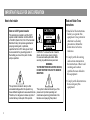
Webstar Cable Modem
Model DPX100 Cable Modem
Model DPX120 Cable Modem
IMPORTANT RULES FOR SAFE OPERATION
Read and Retain These
Instructions
Note to the Installer
Note to CATV System Installer
This reminder is provided to call the CATV
system installer’s attention to Article 820-40
of the NEC (Section 54, Part I of the Canadian
Electrical Code), that provides guidelines for
proper grounding and, in particular,
specifies that the CATV cable ground shall
be connected to the grounding system of
the building, as close to the point of cable
entry as practical.
This symbol is intended to alert you that
uninsulated voltage within this product may
have sufficient magnitude to cause electric shock.
Therefore, it is dangerous to make any kind of
contact with any inside part of this product.
2
CAUTION
RISK OF ELECTRIC SHOCK
DO NOT OPEN
AVIS
CAUTION: To reduce the risk of electric
shock, do not remove cover (or back).
No user-serviceable parts inside. Refer
servicing to qualified service personnel.
WARNING
TO PREVENT FIRE OR ELECTRIC SHOCK,
DO NOT EXPOSE THIS UNIT TO RAIN OR
MOISTURE.
This symbol is intended to alert you of the
presence of important operating and
maintenance (servicing) instructions in the
literature accompanying this product.
• Read all of the instructions
before you operate this
equipment. Give particular
attention to all safety
precautions. Retain the
instructions for future
reference.
• Comply with all warning
and caution statements in
the instructions. Observe all
warning and caution
symbols that are affixed to
this equipment.
• Comply with all instructions
that accompany this
equipment.
IMPORTANT RULES FOR SAFE OPERATION, continued
Cleaning the Equipment
Before cleaning this equipment, unplug it from the
electrical outlet. Use a damp cloth to clean this
equipment. Do not use a liquid cleaner or an aerosol
cleaner. Do not use a magnetic/static cleaning device
(dust remover) to clean this equipment.
Placement
Place this equipment in a location that is close enough
to an electrical outlet to accommodate the length of the
power cord. Place this equipment on a stable surface.
The surface must support the size and weight of this
equipment. Place this equipment either horizontally or
vertically.
WARNING:
Avoid personal injury and damage to this
equipment. An unstable surface may cause
this equipment to fall.
Accessories
Ventilation
This equipment has openings for ventilation that protect
it from overheating. To ensure the reliability of this
equipment, do not obstruct the openings.
• Do not place other equipment, lamps, books, or any
other object on the top of or beside this equipment.
• Do not place this equipment in any of the locations that
follow:
- On a bed, sofa, rug, or similar surface
- Over a radiator or a heat register
- In an enclosure, such as a bookcase or equipment
rack, unless the installation provides proper
ventilation
Overloading
Do not overload electrical outlets, extension cords, or
integral convenience receptacles, as this can result in a
risk of fire or electric shock. For equipment that
requires battery power or other sources to operate,
refer to the operating instructions for that equipment.
Do not use accessories with this equipment unless
recommended by your cable service provider.
3
IMPORTANT RULES FOR SAFE OPERATION, continued
Object and Liquid Entry
Never push objects of any kind into this product
through openings as they may touch dangerous voltage
points or short out parts that could result in a fire or
electric shock. Do not expose this equipment to liquid or
moisture. Do not place this equipment on a wet surface.
Do not spill liquids on or near this equipment.
Lightning and Power Surges
Plug your equipment into a surge protector in order to
reduce the risk of damage from lightning strikes and
power surges. If you are unsure of the type of surge
protector to use, contact your cable service provider.
Servicing
Do not open the cover of this equipment. If you open the
cover, your warranty will be void. Refer all servicing to
qualified personnel only. Contact your cable service
provider for instructions.
Power Cord Protection
Arrange all power cords so that people cannot walk on
the cords, place objects on the cords, or place objects
against the cords, which can damage the cords. Pay
particular attention to cords that are at plugs, at
electrical outlets, and at the places where the cords exit
the equipment.
Power Sources
A label on the AC power adapter which is supplied
with this equipment, indicates the correct power source
for this equipment. Operate this equipment only from
an electrical outlet that has the voltage and frequency
that the label indicates.
If you are unsure of the type of power supply to your
residence, consult Scientific-Atlanta, Inc., or your local
power company.
Grounding
This equipment may be provided with a three-prong
plug. Properly ground (earth) this equipment by
inserting the plug into a grounded electrical, threesocket outlet. If you are unable to insert this plug fully
into the outlet, contact an electrician to replace your
obsolete outlet.
4
IMPORTANT RULES FOR SAFE OPERATION, continued
Checklist
Damage that Requires Service
Equipment Checklist
For damage that requires service, unplug this equipment
from the electrical outlet. Contact your cable service
provider when any of the following situations occur:
• There is damage to the power cord or plug
• Liquid enters the equipment
• A heavy object falls on the equipment
• There is exposure to rain or water
• Operation is not normal (the instructions describe the
proper operation)
• If you drop this equipment, or damage the cabinet of
this equipment
• If this equipment exhibits a distinct change in
performance
Upon completion of any service or repairs to this
equipment (cable modem), ask the service technician to
perform safety checks to determine that the equipment
is in proper operating condition.
Before you install your cable modem, check the
items in the carton. The carton contains the
following items, except as noted:
• One WebSTAR™ Cable Modem
• One Ethernet cable (CAT5/RJ-45)
• One USB cable (not included with all
models)
• One Power Adapter with power cord
• One CD-ROM containing the user’s guide
and the USB drivers
Note: You will need an optional cable
signal splitter and additional standard RF
coaxial cable if you want to connect a VCR,
a Digital Home Communications Terminal
(DHCT) or a set-top converter, or a TV to
the same cable connection as your cable
modem.
5
Overview
Contents
Overview ............................................................................ 6
Before You Begin .............................................................. 7
System Requirements ...................................................... 8
WebSTAR Cable Modem Front Panel ........................... 9
WebSTAR Cable Modem Back Panel .......................... 10
WebSTAR Cable Modem Features
Welcome to the world of high-speed Internet access.
Your new WebSTAR Model DPX100 or Model DPX120
Cable Modem offers the following outstanding features:
•
Two-way, high-speed data rates much faster than
56K analog modems, ISDN, or DSL
•
Plug and Play operation for easy setup and
installation
•
10/100BaseT Ethernet or USB connection
•
Clear LED display
•
Vertical or horizontal placement
•
CableLabs Data Over Cable System Interface
Specifications (DOCSIS) certification (for the Model
DPX100), and Euro-DOCSIS certification (for the
Model DPX120) ensures interoperability with
other certified cable modems and certified cable
service providers
•
Cable modem software can be upgraded
automatically by your cable service provider
Modem Installation ......................................................... 11
TCP/IP Configuration .................................................... 12
USB Driver Installation ................................................. 16
Troubleshooting ............................................................. 19
Tips for Improved Performance .................................. 21
Detailed Front Panel Indicator Functions .................... 22
Notices .............................................................................. 25
United States FCC Compliance ...................... Back cover
6
Before You Begin
Contacting Your Local Cable Service Provider
You need to set up an Internet access account with
your local cable service provider in order to use your
cable modem. When you contact your cable service
provider, verify the following conditions:
• Does the cable service to your home support
two-way, DOCSIS or Euro-DOCSIS-compatible
cable modem access? If your cable service provider
does not provide two-way service, this modem will
not be able to communicate with your cable service
provider’s Internet access service.
• Do you have an active RF coaxial cable
connection near your PC? If your current
cable input is not conveniently located near
your PC, your cable service provider can install
one.
You must also give your cable service provider
the following information:
• The serial number of the modem
• The Media Access Control (MAC) address of
the modem
These numbers appear on a black and white bar code
label located on the bottom of the cable modem. The
serial number consists of a series of alpha-numeric
characters preceded by S/N. The MAC address
consists of a series of alphanumeric characters
preceded by MAC. The following illustration shows
a sample bar code label.
• Do you have an Internet access account? Your
cable service provider will set up your Internet
access account, and will become your Internet
Service Provider (ISP) to enable you to send
and receive e-mail, access the World Wide Web,
and receive other Internet services.
T9958
7
System Requirements
Introduction
This section provides hardware and software
requirements.
• A PC with a Windows 98/98SE/ME/2000
or XP operating system
Minimum System Requirements for PCs
• A master USB port installed in your PC
• A PC with a Pentium MMX 133 processor or
greater
• 32 MB of RAM
• Netscape or Internet Explorer
• CD-ROM drive
Minimum System Requirements for Macintosh
• MAC OS 7.5
• 32 MB of RAM
System Requirements for an Ethernet Connection
• A PC with Windows 95 operating system
(or later) with TCP/IP protocol installed, or an
Apple Macintosh computer with TCP/IP
protocol installed
• An active 10/100BaseT Ethernet network
interface card (NIC) installed in your PC
8
System Requirements for a USB Connection
Selecting a Location for Your Modem
Select the location for your workspace and
consider these recommendations:
• Position your PC and cable modem so that they are
located near your cable input. There should be
plenty of room to guide the cables away from the
modem without straining or crimping them.
• Air flow around the cable modem should not be
restricted.
• Read this user’s guide thoroughly before
installing the cable modem.
WebSTAR Cable Modem Front Panel
Front Panel Indicators
1
POWER
Illuminates solid green to indicate that power is being applied to the cable
modem
2
PC
Illuminates solid green to indicate that an Ethernet/USB carrier is
present
Blinks to indicate that Ethernet/USB data is being transferred between
the PC and the cable modem
ER
POW
PC
A
DAT
LE
CAB
1
2
3
4
3
DATA
Blinks to indicate that data is being transferred between the modem and
the cable network
4
CABLE
Illuminates solid green when the modem is registered on the network and
fully operational. This indicator blinks to indicate one of the following
conditions:
• The cable modem is booting up and not ready for data
• The cable modem is scanning the network and attempting to register
• The cable modem has lost registration on the network and will continue
blinking until it registers again
• Blinks very slowly (once every 5 seconds) to indicate that Cable Modem
Access Protection is enabled
Note: Once the cable modem is successfully registered on the network, the
POWER and CABLE indicators illuminate continuously to indicate that the
cable modem is active and fully operational.
T9916
See Detailed Front Panel Indicator Functions later in this guide for more
information on front panel indicator functions.
9
WebSTAR Cable Modem Back Panel
Back Panel Components
1 POWER
POWER
12 VDC
RESET
ETHERNET
3
USB
4
CABLE
IN
5
T9917
10
Note: Only use the power cord and the AC power adapter that are
provided with your cable modem.
1
2
Connects the cable modem to the DC output of the AC power
adapter that is provided with your cable modem
2 RESET
Reset-to-Default button (Factory Reset)
CAUTION:
This button is for maintenance purposes only. Do not use!
3 ETHERNET
RJ-45 Ethernet port connects to the Ethernet port on your PC
4 USB
12 Mbps USB port connects to the USB port on your PC
5 CABLE IN
F-Connector connects to an active cable signal from your cable
service provider
CAUTION:
Do not connect your PC to both the Ethernet and USB ports at
the same time.
Note: You can connect two separate PCs to the cable modem at
the same time by connecting one to the Ethernet port and one to
the USB port. See Modem Installation next in this guide.
Modem Installation
Installing the Modem
The following diagram illustrates one of the
various connection options that are available
to you.
RF
Cable
Cable
Splitter
CH+
POWER
12 VDC
Power Supply
ETHERNET
Power
Supply
RESET
USB
VOLñ
VOL+
MENU
GUIDE
INFO
A/B
POWER
CHñ
BYPASS
RF
Cables
Cable-Ready TV,
VCR, or Set-Top
Converter
PC
CABLE
IN
Follow these steps for proper installation.
1. Power down your PC and unplug it from the power source.
2. Connect the active RF coaxial cable to the CABLE IN
connector. Use an optional cable signal splitter to add a
TV, a DHCT or set-top converter, or a VCR.
3. Connect your PC to either the Ethernet port or the USB
port using the appropriate data cable. You can connect
two separate PCs to the cable modem at the same time
by connecting one to the Ethernet port and one to the
USB port.
4. Insert the AC power adapter cord into the DC power
connector on the back of the cable modem, and then
plug the power adapter into an AC power source.
5. The cable modem will then begin an automatic search
to locate and sign on to the broadband data network.
This process may take up to 5 minutes. The modem
will be ready for use when the CABLE indicator on the
front panel stops blinking and illuminates continuously.
6. Plug in and power up your PC.
7. Choose one of the following options:
• To configure the TCP/IP protocol for Ethernet—
see TCP/IP Configuration.
• To install the USB Drivers for USB—see USB
Driver Installation.
T9918
Ethernet
Cable
Note: Professional installation may be available.
Contact your local cable service provider for
further assistance.
11
TCP/IP Configuration
Introduction
This section contains instructions for configuring
the WebSTAR cable modem to run in Windows
or Macintosh environments. In addition, TCP/IP
protocol in a Windows environment is different
for the Windows 95/98/ME/and 2000 versions.
Follow the appropriate instructions in this section
to configure the TCP/IP protocol.
Windows 95/98/ME
Follow the instructions in this section to configure
the WebSTAR cable modem for TCP/IP in a
Windows 95/98/ME environment.
Configuring the TCP/IP Protocol for Windows 95/98/ME
Before you install your cable modem, you need to
have either an Ethernet Network Interface Card
(NIC) with TCP/IP communications protocol, or a
USB network interface installed on your system.
Follow these steps to install and configure the
TCP/IP protocol for Windows 95/98/ME
environments.
12
1. Click Start, select Settings, and choose
Control Panel. The Control Panel window opens.
2. In the Control Panel window, doubleclick the Network icon. A list of installed
network components appears.
3. Under the Configuration tab, read the list of
installed network components to verify your
PC contains the TCP/IP protocol.
4. Does your PC have the TCP/IP protocol?
• If yes, go to step 8.
• If no, click Add.
5. Click Protocol, and then click Add.
6. In the Manufacturers list, click Microsoft.
7. In the Network Protocols list, click TCP/IP, and
then click OK.
8. Click the TCP/IP Ethernet Adapter protocol,
and then choose Properties.
9. Click the IP Address tab, and then select
Obtain an IP address automatically.
TCP/IP Configuration, continued
10. Click the Gateway tab and verify that these
fields are empty. If they are not empty,
highlight and delete all information from the
fields.
11. Click the DNS Configuration tab, and then
select Disable DNS.
12. Click OK. The Copying Files window opens.
13. When the system finishes copying the files,
click OK.
14. Close all networking windows.
15. When the System Settings Change dialog box
opens, click YES to restart your computer.
1.
Click Start, and then click Run to open the
Run window.
2.
Type winipcfg in the Open field, and click
OK to execute the winipcfg command. The IP
Configuration window opens.
3.
Click the down arrow to the right of the top
field, and select the Ethernet adapter that is
installed on your PC. The IP Configuration
window displays the Ethernet adapter
information.
4.
Click Release, and then click Renew. The IP
Configuration window displays a new IP
address.
5.
Click OK to close the IP Configuration window.
Renewing the IP Address for Windows 95/98/98SE/ME
If your PC cannot access the Internet after the
cable modem is online, it is possible that your
PC did not renew its IP address. Follow these steps
to renew the IP address on your PC.
Note: If you have Windows 2000, Windows
NT, or Windows XP, consult your User’s
Manual for the procedure for renewing the IP
address on your PC.
13
TCP/ IP Configuration, continued
Windows 2000
Follow these steps to install and configure the
TCP/IP protocol for Windows 2000 environments.
1.
2.
3.
14
Click Start, select Settings, and choose
Network and Dial-up Connections. The
Network and Dial-up Connections window
opens.
In the Network and Dial-up Connections
window, double-click the Local Area
Connection icon. The Local Area Connection
Status window opens.
In the Local Area Connection Status
window, click Properties. The Local Area
Connection Properties window opens.
4.
In the Local Area Connection Properties
window, click Internet Protocol (TCP/IP), and
then click Properties. The Internet Protocol
(TCP/IP) Properties window opens.
5.
In the Internet Protocol (TCP/IP) Properties
window select both Obtain an IP address
automatically, and Obtain DNS server
address automatically; then, click OK.
6. When the Local Network window opens, click
Yes to restart your computer.
Macintosh
Follow these steps to verify that the TCP/IP
communications protocol and an Ethernet device
are installed on your Macintosh computer.
1. Click the Apple icon in the upper left corner
of the Finder. Scroll down to Control Panels,
and then click TCP/IP.
2. Click Edit on the Finder (gray bar) at the top
of the screen. Scroll down to the bottom of the
menu, and then click User Mode.
3. Click Advanced in the User Mode window,
and then click OK.
4. Click the Up/Down selector arrows located
to the right of the Connect Via section of the
TCP/IP window, and then click Using DHCP
Server.
TCP/IP Configuration, continued
5.
6.
7.
Click Options in the TCP/IP window, and
then click Active in the TCP/IP Options
window.
Note: In some cases, the Load only when
needed option will not appear. If it appears,
select the option. A check mark appears in the
option.
Verify that the Use 802.3 option located in
the upper right-hand corner of the TCP/IP
window is unchecked. If there is a check
mark in the option, deselect the option, and
then click Info in the lower left-hand corner.
Is there a Hardware Address listed in this
window?
• If yes, click OK. To close the TCP/IP
Control Panel window, click File, and
then scroll down to click Close. You have
completed this procedure.
8.
With the power off, simultaneously press
and hold down the Command (Apple),
Option, P, and R keys on your keyboard.
Keeping those keys pressed down, power on
your Macintosh. The computer will start, and
you will hear the Apple chime; do not release
these keys.
9.
Continue pressing these keys for up to
three chimes, then release the keys and
allow the computer to restart.
10. When your computer fully reboots, repeat
steps 1 through 7 to verify that all TCP/IP
settings are correct. If your computer still does
not have a Hardware Address, contact your
authorized Apple dealer or Apple technical
support center.
• If no, you must power down your
Macintosh.
15
USB Driver Installation
Introduction
This section contains instructions for installing the
WebSTAR cable modem USB drivers if your PC is
equipped with a USB interface and a Windows
98/98SE/ME/2000/or XP operating system. The USB
driver installation procedures are different for each
operating system. Follow the appropriate instructions
in this section for your operating system. If your PC
does not have a USB interface, you may skip this section.
Windows 98/98SE/ME
Follow these steps to install the WebSTAR cable
modem USB drivers for Windows 98/98SE/and
ME environments.
1. Insert the USB Cable Modem Driver
Installation disk into the CD-ROM drive of
your PC.
2. Wait until the Power and Cable indicators
on the cable modem illuminate solid green;
then, plug the USB cable into the USB port
on your PC. The Add New Hardware Wizard
window opens.
16
3. Click Next.
4. In the Add New Hardware Wizard window,
select Search for the best driver for your
device (Recommended), then click Next.
5. In the Add New Hardware Wizard window,
select CD-ROM drive, then click Next.
6. In the Add New Hardware Wizard window,
select The updated driver (Recommended),
then click Next.
7. In the Add New Hardware Wizard window,
click Next. The Copying Files window
opens. After 10 to 20 seconds have passed, the
Add New Hardware Wizard window reopens.
8. Click Finish. The System Settings Change
window opens. The driver installation is
complete.
9. Click Yes to restart your computer.
USB Driver Installation, continued
Windows 2000
Follow these steps to install the WebSTAR cable
modem USB Drivers for Windows 2000
environments.
6.
In the Found New Hardware Wizard window,
click Next. The system searches for the driver
file for your hardware device.
1. Insert the USB Cable Modem Driver
Installation Disk into the CD-ROM driver of
your PC.
7.
After the system finds the USB driver, the
Digital Signature Not Found window opens
displaying a confirmation message to
continue the installation. Click Yes to continue
the installation. The Found New Hardware
Wizard window reopens with a message that
the installation is complete.
8.
Click Finish to close the Found New Hardware
Wizard window.
2. Wait until the Power and Cable indicators on
the cable modem illuminate solid green; then,
plug the USB cable into the USB port on your
PC. The Found New Hardware Wizard
window opens.
3. In the Found New Hardware Wizard window,
click Next.
4. In the Found New Hardware Wizard window,
select Search for a suitable driver for my
device(recommended), then click Next.
5. In the Found New Hardware Wizard window,
select CD-ROM drives, then click Next.
17
USB Driver Installation, continued
Windows XP
Follow these steps to install the WebSTAR cable
modem USB drivers for Windows XP
environments.
1. Insert the USB Cable Modem Driver
Installation disk into the CD-ROM drive of
your PC.
2. Wait until the Power and Cable indicators on
the cable modem illuminate solid green; then,
plug the USB cable into the USB port on your
PC. The Found New Hardware Wizard
window opens.
3. In the Found New Hardware Wizard window,
select Install from a list or specific location
(Advanced), then click Next.
4. In the Found New Hardware Wizard window,
select Search removable media (floppy,CDROM), and then click Next. The Hardware
Installation window opens.
18
5. In the Hardware Installation window, click
Continue Anyway to continue the installation.
6. The Found New Hardware Wizard window
reopens with a message that the installation is
complete.
7. Click Finish to close the Found New Hardware
Wizard window.
Troubleshooting
Frequently Asked Questions
Q. What if I don’t subscribe to cable TV?
A. If cable TV is available in your area, data service
may be made available with or without subscribing to
cable TV service. Contact your local cable service
provider for complete information on cable services,
including high-speed Internet access.
Q. How do I arrange for installation?
A. Professional installation from your cable service
provider may be provided. A professional installation
ensures proper cable connection to the modem and to
your PC, and ensures proper configuration of all
hardware and software settings. Contact your cable
service provider for more information about installation.
Q. How does the WebSTAR Cable Modem connect to
my computer?
A. The cable modem connects to the USB port or the
10/100BaseT Ethernet port on your PC. If your PC is
not equipped with an Ethernet interface, an Ethernet
card is available from your local PC or office supply
retailer, or from your cable service provider.
Q. Once my cable modem is connected, how do I
access the Internet?
A. Your local cable service provider becomes your
Internet Service Provider (ISP), offering a wide range of
services including e-mail, chat, news, and information
services. Your cable service provider will provide the
software you will need.
Q. Can I watch TV and surf the Internet at the same
time?
A. Absolutely! If you subscribe to cable television
service, you can watch TV and use your cable modem
at the same time by connecting your TV and your cable
modem to the cable network using an optional cable
signal splitter.
Q. Can I run more than one device on the
modem?
A. Yes—a single WebSTAR cable modem will support
up to 31 Ethernet devices utilizing a user-supplied
Ethernet hub, that you can purchase at your local PC or
office supply retailer. Another user at your location can
simultaneously connect to the USB port on the cable
modem. Contact your cable service provider for further
assistance.
19
Troubleshooting, continued
Common Troubleshooting Issues
The modem does not register an Ethernet
connection.
The modem does not register a cable
connection.
Even new computers do not always have
Ethernet capabilities. Be sure to verify that
your computer has a 10/100BaseT Ethernet card
and that the Ethernet driver software is
properly installed. If you purchase and install
an Ethernet card, follow the installation
instructions very carefully.
•
The modem works with a standard,
75-ohm, RF coaxial cable. If you are using a
different cable, your cable modem will not
function properly. Contact your cable service
provider to determine whether you are using
the correct cable.
•
Verify that you have followed the
procedure for Renewing the IP address
for Windows 95/98/98SE and ME PCs
earlier in this guide.
•
Your NIC card or USB interface may be
malfunctioning. Refer to the troubleshooting information in the NIC or
USB documentation.
The modem does not register an Ethernet connection
after connecting to a hub.
If you are connecting multiple PCs to the cable modem,
you should first connect the modem to the up-link
port of the hub. The LINK LED of the hub will
illuminate continuously.
20
Tips for Improved Performance
Check and Correct
If your cable modem does not perform as
expected, the following tips may help. If you need
further assistance, contact your cable service
provider.
• Verify that the plug to your cable modem AC
adapter is properly inserted into an electrical
outlet.
• Verify that your cable modem AC adapter is
not plugged into an electrical outlet that is
controlled by a wall switch. If the electrical
outlet is controlled by a wall switch, make sure
the switch is in the ON position.
• Verify that the Power and Cable indicators on
the front panel of your cable modem are
illuminated.
• Verify that all cables are properly connected,
and that you are using the correct cables.
• Verify that your TCP/IP is properly installed
and configured if you are using the Ethernet
connection.
• Verify that you have followed the procedure for
Installing the USB Drivers for Windows 98
98SE/ME/2000/XP, earlier in this guide, if you
are using the USB connection.
• Verify that you have called your cable service
provider and given them the serial number
and MAC address of your cable modem.
• If you are using a cable signal splitter so
that you can connect the cable modem to
other devices, remove the splitter and
reconnect the cables so that the cable
modem is connected directly to the cable input.
If the cable modem now functions properly,
the cable signal splitter may be defective and
may need to be replaced.
• Verify that your cable service is active and that
it supports two-way service.
21
Detailed Front Panel Indicator Functions
This chart illustrates the sequence of steps and the corresponding appearance of the cable modem front panel indicators
during power up, calibration, and registration on the network. Use this chart to troubleshoot the power up, calibration,
and registration process of your cable modem.
Front Panel Indicators During Initial Power Up, Calibration, and Registration
2
3
4
5
6
7
8
Front Panel Power
Indicator
Up
Self
Test
Downstream
Scan
Downstream
Signal Lock
Ranging
Requesting
IP Address
Registering
Registration
Completed
1 POWER
ON
ON
ON
ON
ON
ON
ON
ON
2
PC
OFF
ON
ON
or
BLINKING
ON
or
BLINKING
ON
or
BLINKING
ON
or
BLINKING
ON
or
BLINKING
ON
3
DATA
OFF
ON
OFF
OFF
OFF
ON
SLOW
BLINKING
Step
4 CABLE
1
MOMENTARY
ON
1 time per second
OCCASIONAL OCCASIONAL OCCASIONAL
BLINKING
BLINKING
BLINKING
OFF
SLOW
BLINKING
RAPID
BLINKING
ON
ON
1 time per second 4 times per second
T9919
22
Detailed Front Panel Indicator Functions, continued
This chart illustrates the appearance of the cable modem front panel indicators during normal operations.
Front Panel Indicators During Normal Operations
Step
9
Front Panel
Indicator
Normal Operations
(Bold denotes normal)
1 POWER ON
2
PC
ON - When a single device is connected to either the Ethernet or USB port and no data is being
sent to or from the modem.
BLINKS - When one device is connected and data is being transferred between the consumer
equipment and the modem.
OFF - When no devices are connected to either the Ethernet or USB ports.
Note: With both Ethernet and USB devices connected to the modem at the same time, when data is being
transferred through only one of the devices (Ethernet or USB), the indicator will illuminate continuously.
Whenever data is being sent through both data ports (Ethernet and USB) simultaneously, the indicator will
blink as described above.
3
DATA
4 CABLE
BLINKS - To indicate data is being transferred between the modem and the network.
ON
T9920
23
Detailed Front Panel Indicator Functions, continued
This chart describes the appearance of the cable modem front panel indicators during special conditions to show that
cable modem access protection is enabled, or that you have been denied network access.
Front Panel Indicators During Special Conditions
Front Panel
Indicator Cable Modem Access Protection Enabled
Network Access Denied
SLOW BLINKING
1 POWER
OFF
2
PC
OFF
3
DATA
OFF
4
CABLE
VERY SLOW BLINKING
SLOW BLINKING
1 time every 5 seconds
1 time per second
1 time per second
SLOW BLINKING
1 time per second
SLOW BLINKING
1 time per second
T9921
24
Notices
Trademarks
Scientific-Atlanta and the Scientific-Atlanta ARCs logo
are registered trademarks of Scientific-Atlanta, Inc.
WebSTAR and “Bringing the Interactive Experience Home”
are trademarks of Scientific-Atlanta, Inc.
Other trademarks listed herein are the property of their
respective owners.
Disclaimer
Scientific-Atlanta, Inc. assumes no responsibility for errors or
omissions that may appear in this guide. Scientific-Atlanta
reserves the right to change this guide at any time without
notice.
Software Use Notice
The software described in this document is copyrighted and
furnished to you under a license agreement. You may only use
or copy this software in accordance with the terms of your
license agreement.
Firmware Use Notice
The firmware in this equipment is copyrighted. You may only
use the firmware in the equipment in which it is provided. Any
reproduction or distribution of this firmware, or any portion of
it, without express written consent is prohibited.
Documentation Copyright Notice
© 2002 Scientific-Atlanta, Inc. All rights reserved.
Printed in the United States of America.
Information in this document is subject to change without
notice. No part of this document may be reproduced in any form
without the express written permission of Scientific-Atlanta, Inc.
25
United States FCC Compliance
This device complies with Part 15 of FCC Rules. Operation is
subject to the following two conditions: 1) the device may not
cause harmful interference, and 2) the device must accept any
interference received, including interference that may cause
undesired operation.
WebSTAR Cable Modem
Model DPX100
Scientific-Atlanta, Inc.
5030 Sugarloaf Parkway
Lawrenceville, Georgia 30044 USA
Telephone: 770-236-1077
• Connect the equipment into an outlet on a circuit different
from that to which the receiver is connected
Canada EMI Regulation
• Consult your cable company or an experienced radio/TV
technician for help
Any changes or modifications not expressly approved by
Scientific-Atlanta could void the user’s authority to operate
the equipment.
Important: The information shown in the FCC Declaration of
Conformity paragraph below is a requirement of the FCC and
is intended to supply you with information regarding the
FCC approval of this device. The phone numbers listed are for
FCC-related questions only and not intended for questions
regarding the connection or operation for this device. Please contact
your cable service provider for any questions you may have
regarding the operation or installation of this device.
26
FCC Declaration of Conformity
This equipment has been tested and found to comply with the
applicable limits of Part 15 of FCC Rules. These limits are
designed to provide reasonable protection against harmful
interference in a residential installation. This equipment
generates, uses, and can radiate radio frequency energy and,
if not installed and used in accordance with the instructions,
may cause harmful interference to radio or TV reception,
which can be determined by turning the equipment off and
on. The user is encouraged to try to correct the interference by
one or more of the following measures:
• Increase the separation between the equipment and
receiver
This Class B digital apparatus meets all requirements of the
Canadian Interference Causing Equipment Regulations.
Cet appareil numérique de la classe B respecte toutes les
exigences du Réglement sur le matériel brouilleur du Canada.
United States: Scientific-Atlanta, Inc., 5030 Sugarloaf Parkway,
Box 465447, Lawrenceville, GA 30042; Tel: 770-236-5000;
TWX: 810-799-4912; Telex: 0542898
Europe: Scientific-Atlanta Europe GmbH, Westerbachstrasse 28-32,
61476 Kronberg, Germany; Tel: 49-6173-928-000
Asia-Pacific: Scientific-Atlanta (Singapore) Pte. Ltd., 1 Claymore Drive,
#08-11 Orchard Towers, Singapore 229594; Tel: 65-733-4314
Latin America: Scientific-Atlanta Argentina S.A., C. Pellegrini 1149 Piso 11o
Capital Federal 1011 Buenos Aires, Argentina; Tel: 54-11-4325-2800
www.scientificatlanta.com
© 2002 Scientific-Atlanta, Inc. All rights reserved.
Printed in USA
January 2002
Part Number 749610 Rev A