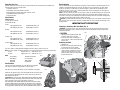
1
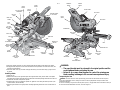
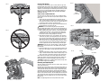
Questions? See us on the World Wide Web at www.dewalt.com
INSTRUCTION MANUAL
DW717-XE
254 mm (10") DOUBLE BEVEL SLIDING COMPOUND MITER SAW
TABLE OF CONTENTS
DOUBLE INSULATION INSTRUCTIONS............................................................................................................1
OPERATION ...............................……………………………………………………………………………7
SAFETY INSTRUCTIONS FOR ALL TOOLS ......................................…………………………………………1
SWITCH ..................................................................................................................................................7
ADDITIONAL SAFETY RULES ....................................……………………………………………………….1
CUTTING WITH YOUR SAW .....................................................................................................................7
ELECTRICAL CONNECTION ....................................…………………………………………………………3
CROSSCUTS .................................................................................................................................................... 7
ACCESSORIES ...............................................................................................................................................3
BEVEL CUTS .................................................................................................................................................... 8
BLADE DESCRIPTIONS ..................................................................................................................................3
QUALITY OF CUT.............................................................................................................................................. 8
UNPACKING YOUR SAW ....................................……………………………………………………………4
BODY AND HAND POSITION ............................................................................................................................ 8
SPECIFICATIONS ............................................................................................................................................4
CLAMPING THE WORKPIECE ..................................................................................................................8
FAMILIARIZATION...............................………………………………………………………………………4
SUPPORT FOR LONG PIECES ..................................................................................................................9
BENCH MOUNTING ................................……………………………………………………………………4
CUTTING PICTURE FRAMES, SHADOW BOXES
AND OTHER FOUR-SIDED PROJECTS......................................................................................................9
CHANGING OR INSTALLING A NEW SAW BLADE ...........................................................................................4
REMOVING THE BLADE .................................................................................................................................4
INSTALLING THE BLADE ....................................……………………………………………………………5
TRANSPORTING THE SAW.....................................…………………………………………………………5
ADJUSTMENTS..............................…………………………………………………………………………6
MITER SCALE ADJUSTMENT.................................………………………………………………………6
MITER POINTER ADJUSTMENT .................................……………………………………………………6
BEVEL SQUARE TO TABLE ........................................................................................................................6
BEVEL POINTER ........................................................................................................................................6
BEVEL STOP .............................................................................................................................................6
FENCE ADJUSTMENT ............................…………………………………………………………………6
AUTOMATIC ELECTRIC BRAKE ..................................................................................................................6
GUARD ACTUATION AND VISIBILITY..................................………………………………………………6
KERF PLATE ADJUSTMENT .......................................................................................................................6
RAIL GUIDE ADJUSTMENT ........................................................................................................................6
MITER LOCK ADJUSTMENT.......................................................................................................................6
BRUSHES ..............................………………………………………………………………………………7
CONTROLS ....................................................................................................................................................7
CUTTING TRIM MOLDING AND OTHER FRAMES .....................................................................................9
CUTTING COMPOUND MITERS ................................................................................................................9
CUTTING BASE MOLDING .......................................................................................................................9
CUTTING CROWN MOLDING ...................................................................................................................9
SPECIAL CUTS ............................................................................................................................................10
REMOVING AND REPLACING THE BELT .......................................................................................................11
MAINTENANCE ............................................................................................................................................12
SERVICE INFORMATION ...............................................................................................................................12
WARRANTY .................................................................................................................................................12
TROUBLESHOOTING GUIDE .........................................................................................................................12
TABLE 1: COMPOUND MITER CUT ...............................................................................................................13
• SECURE THE WORKPIECE. Use clamps or a vise to hold the workpiece on the table and against the fence
or when your hand will be dangerously close to the blade (within 6"). It is safer than using your hand and it
frees both hands to operate tool.
• DON’T OVERREACH. Keep proper footing and balance at all times. Loss of balance may cause personal
injury.
• MAINTAIN TOOLS WITH CARE. Keep tools sharp and clean for best and safest performance. Follow
instructions for lubricating and changing accessories. Poorly maintained tools and machines can further
damage the tool or machine and/or cause injury.
• TURN THE MACHINE “OFF”, AND DISCONNECT THE MACHINE FROM THE POWER SOURCE before
installing or removing accessories, before adjusting or changing set-ups, when making repairs or changing
locations. An accidental start-up can cause injury. Do not touch the plug’s metal prongs when unplugging or
plugging in the cord.
• REDUCE THE RISK OF UNINTENTIONAL STARTING. Make sure that the switch is in the “OFF” position
before plugging in the power cord.
• USE PROPER EXTENSION CORD. Make sure your extension cord is in good condition. If your product is
equipped with a cordset, use only 3-wire extension cords that have 3-prong grounding-type plugs and 3-pole
receptacles that accept the tool’s plug. When using an extension cord, be sure to use one heavy enough to
carry the current your product will draw. An undersized cord will cause a drop in line voltage resulting in loss
of power and overheating. The following table shows the correct size to use depending on cord length and
nameplate ampere rating. If in doubt, use the next heavier gage. The smaller the gage number, the heavier the
cord.
MINIMUM GAUGE FOR CORD SETS
For Cable length (m):
7.5
15
25
30
45
60
Use Cable with minimum rating (Amperes)
Tool Amperes
0 - 3.4
7.5
7.5
7.5
7.5
7.5
7.5
3.5 - 5.0
7.5
7.5
7.5
7.5
10
15
5.1 - 7.0
10
10
10
10
15
15
7.1 - 12.0
15
15
15
15
20
20
12.1 - 20.0
20
20
20
20
25
–
Definitions: Safety Guidelines
The definitions below describe the level of severity for each signal word. Please read the manual and pay
attention to these symbols.
DANGER: Indicates an imminently hazardous situation which, if not avoided, will result in death or serious
injury.
WARNING: Indicates a potentially hazardous situation which, if not avoided, could result in death or
serious injury.
CAUTION: Indicates a potentially hazardous situation which, if not avoided, may result in minor or
moderate injury.
CAUTION: Used without the safety alert symbol indicates a potentially hazardous situation which, if not
avoided, may result in property damage.
IF YOU HAVE ANY QUESTIONS OR COMMENTS ABOUT THIS OR ANY DEWALT TOOL, CALL US AT: 1800 654 155
(Aust) or 09 259 1111 (NZ).
Important Safety Instructions
WARNING: Read all instructions before operating product. Failure to follow all instructions listed below
may result in electric shock, fire and/or serious injury.
READ ALL INSTRUCTIONS
Double Insulation
Double insulated tools are constructed throughout with two separate layers of electrical insulation or one double
thickness of insulation between you and the tool’s electrical system. Tools built with this insulation system are not
intended to be grounded.
NOTE: Double insulation does not take the place of normal safety precautions when operating this tool. The
insulation system is for added protection against injury resulting from a possible electrical insulation failure within
the tool.
CAUTION: WHEN SERVICING USE ONLY IDENTICAL REPLACEMENT PARTS. Repair or replace damaged cords.
Safety Instructions For All Tools
• CHECK for DAMAGED PARTS. Before further use of the tool, a guard or other part that is damaged should
be carefully checked to determine that it will operate properly and perform its intended function—check for
alignment of moving parts, binding of moving parts, breakage of parts, mounting and any other conditions
that may affect its operation. A guard or other part that is damaged should be properly repaired or replaced.
Do not use tool if switch does not turn it on and off.
• USE RECOMMENDED ACCESSORIES. Use only accessories that are recommended by the manufacturer for
your model. Accessories that may be suitable for one tool may be hazardous when used on another tool.
Consult the instruction manual for recommended accessories. The use of improper accessories may cause
risk of injury to persons.
• NEVER STAND ON TOOL. Serious injury could occur if the tool is tipped or if the cutting tool is unintentionally
contacted.
• NEVER LEAVE TOOL RUNNING UNATTENDED. TURN POWER OFF. Don’t leave tool until it comes to a
complete stop. Serious injury can result.
• DO NOT OPERATE ELECTRIC TOOLS NEAR FLAMMABLE LIQUIDS OR IN GASEOUS OR EXPLOSIVE
ATMOSPHERES. Motors in these tools may spark and ignite fumes.
• STAY ALERT, WATCH WHAT YOU ARE DOING, AND USE COMMON SENSE. DO NOT USE THE MACHINE
WHEN YOU ARE TIRED OR UNDER THE INFLUENCE OF DRUGS or ALCOHOL. A moment of inattention while
operating power tools may result in injury.
This miter saw accepts the DEWALT worklight and laser attachments.
WARNING: To reduce the risk of eye injury, ALWAYS use eye protection when operating the miter saw.
• KEEP GUARD IN PLACE and in working order.
• REMOVE ADJUSTING KEYS AND WRENCHES. Form habit of checking to see that keys and adjusting
wrenches are removed from spindle before turning tool on. Tools, scrap pieces, and other debris can be
thrown at high speed, causing injury.
• KEEP WORK AREA CLEAN. Cluttered areas and benches invite accidents.
• DO NOT USE THE MACHINE IN A DANGEROUS ENVIRONMENT. The use of power tools in damp or wet
locations or in rain can cause shock or electrocution. Keep your work area well-lit to avoid tripping or placing
arms, hands, and fingers in danger.
• KEEP CHILDREN AWAY. All visitors should be kept at a safe distance from work area. Your shop is a
potentially dangerous environment.
• MAKE WORKSHOP CHILDPROOF with padlocks, master switches, or by removing starter keys. The
unauthorized start-up of a machine by a child or visitor may result in injury.
• DON’T FORCE TOOL. It will do the job better and be safer at the rate for which it was designed.
• USE RIGHT TOOL. Don’t force tool or attachment to do a job for which it was not designed. Using the
incorrect tool or attachment may result in personal injury.
• WEAR PROPER APPAREL. No loose clothing, gloves, neckties, rings, bracelets, or other jewelry to get
caught in moving parts. Non-slip footwear is recommended. Wear protective hair covering to contain long
hair. Air vents may cover moving parts and should also be avoided.
• ALWAYS USE SAFETY GLASSES. Everyday eyeglasses are NOT safety glasses. Also use face or dust mask
if cutting operation is dusty. ALWAYS WEAR CERTIFIED SAFETY EQUIPMENT:
• ANSI Z87.1 eye protection (CAN/CSA Z94.3)
• ANSI S12.6 (S3.19) hearing protection
• NIOSH/OSHA/MSHA respiratory protection
Additional Safety Rules For Miter Saws
WARNING: Do not allow familiarity (gained from frequent use of your saw) to replace safety rules. Always
remember that a careless fraction of a second is sufficient to inflict severe injury.
• DO NOT OPERATE THIS MACHINE until it is completely assembled and installed according to the
instructions. A machine incorrectly assembled can cause serious injury.
• OBTAIN ADVICE from your supervisor, instructor, or another qualified person if you are not thoroughly familiar
with the operation of this machine. Knowledge is safety.
1
• STABILITY. Make sure the miter saw is placed on a secure supporting surface and does not slip or move
during use. If the mobility kit is installed, raise the moveable caster(s) so saw is in its stationary position.
• FOLLOW ALL WIRING CODES and recommended electrical connections to prevent shock or electrocution.
Protect electric supply line with at least a 15 ampere time-delay fuse or a circuit breaker.”
• MAKE CERTAIN the blade rotates in the correct direction. The teeth on the blade should point in the direction
of rotation as marked on the saw.
• TIGHTEN ALL CLAMP HANDLES, knobs and levers prior to operation. Loose clamps can cause parts or the
workpiece to be thrown at high speeds.
• BE SURE all blade and blade clamps are clean, recessed sides of blade clamps are against blade and arbor
screw is tightened securely. Loose or improper blade clamping may result in damage to the saw and possible
personal injury.
• ALWAYS USE A SHARP BLADE. Check the blade to see if it runs true and is free from vibration. A dull or a
vibrating blade can cause damage to the machine and/or serious injury.
• DO NOT OPERATE ON ANYTHING OTHER THAN THE DESIGNATED VOLTAGE for the saw. Overheating,
damage to the tool and personal injury may occur.
• DO NOT WEDGE ANYTHING AGAINST THE FAN to hold the motor shaft. Damage to tool and possible
personal injury may occur.
• DO NOT force cutting action. Stalling or partial stalling of motor can cause damage. To the machine or blade
and/or serious injury.
• ALLOW THE MOTOR TO COME TO FULL SPEED prior to starting cut. Starting the cut too soon may cause
damage to the machine or blade and/or serious injury.
• NEVER CUT FERROUS METALS (Those with any iron or steel content) or masonry. Either of these can cause
the carbide tips to fly off the blade at high speeds causing serious injury.
• DO NOT USE ABRASIVE WHEELS. The excessive heat and abrasive particles generated by them may
damage the saw and cause personal injury.
• NEVER have any part of your body in line with the path of the saw blade. Personal injury will occur.
• NEVER apply blade lubricant to a running blade. Applying lubricant could cause your hand to move into the
blade resulting in serious injury.
• DO NOT place either hand in the blade area when the saw is connected to the power source. Inadvertent
blade activation may result in serious injury.
• DO NOT PERFORM FREE-HAND OPERATIONS (workpiece not supported by table and fence). Hold the work
firmly against the fence and table. Free-hand operations on a miter saw could cause the workpiece to be
thrown at high speeds, causing serious injury.
• NEVER REACH AROUND or behind the saw blade. A blade can cause serious injury.
• DO NOT reach underneath the saw unless it is unplugged and turned off. Contact with saw blade may cause
personal injury.
• SECURE THE MACHINE TO A STABLE SUPPORTING SURFACE. Vibration can possibly cause the machine to
slide, walk, or tip over, causing serious injury.
• USE ONLY CROSSCUT SAW BLADES recommended for miter saws. For best results, use only zero-degree
or negative hook angles when using carbide-tipped blades. Do not use blades with deep gullets. These can
deflect and contact the guard, and can cause damage to the machine and/or serious injury.
• USE ONLY BLADES OF THE CORRECT SIZE AND TYPE specified for this tool to prevent damage to the
machine and/or serious injury.
• INSPECT BLADE FOR CRACKS or other damage prior to operation. A cracked or damaged blade can come
apart and pieces can be thrown at high speeds, causing serious injury. Replace cracked or damaged blades
immediately.
• CLEAN THE BLADE AND BLADE CLAMPS prior to operation. Cleaning the blade and blade clamps allows
you to check for any damage to the blade or blade clamps. A cracked or damaged blade or blade clamp can
come apart and pieces can be thrown at high speeds, causing serious injury.
• DO NOT use lubricants or cleaners (particularly spray or aerosol) in the vicinity of the plastic guard. The
polycarbonate material used in the guard is subject to attack by certain chemicals.
• ALWAYS USE THE KERF PLATE AND REPLACE THIS PLATE WHEN DAMAGED. Small chip accumulation
under the saw may interfere with the saw blade or may cause instability of workpiece when cutting.
• USE ONLY BLADE CLAMPS specified for this tool to prevent damage to the machine and/or serious injury.
• CLEAN THE MOTOR AIR SLOTS of chips and sawdust. Clogged motor air slots can cause the machine to
overheat, damaging the machine and possibly causing a short which could cause serious injury.
• KEEP ARMS, HANDS, AND FINGERS away from the blade to prevent severe cuts. Clamp all workpieces that
would cause your hand to be within 6" of the saw blade.
• NEVER LOCK THE SWITCH IN THE “ON” position. Severe personal injury may result.
• TURN OFF THE MACHINE and allow the blade to come to a complete stop before raising the arm and prior to
cleaning the blade area, removing debris in the path of the blade, before servicing or adjusting tool. A moving
blade can cause serious injury.
• PROPERLY SUPPORT LONG OR WIDE WORKPIECES. Loss of control of the workpiece can cause injury.
• NEVER cross arms in front of blade while using tool. Always make a dry run (unpowered) before making a
finish cut so that you can check the path of the blade or severe personal injury may result.
• ADDITIONAL INFORMATION regarding the safe and proper operation of power tools (i.e. a safety video)
is available from the Power Tool Institute, 1300 Sumner Avenue, Cleveland, OH 44115-2851 (www.
powertoolinstitute.com). Information is also available from the National Safety Council, 1121 Spring Lake
Drive, Itasca, IL 60143-3201. Please refer to the American National Standards Institute ANSI 01.1 Safety
Requirements for Woodworking Machines and the U.S. Department of Labor OSHA 1910.213 Regulations.
CAUTION: Do not connect unit to electrical power source until complete instructions are read and understood.
WARNING: Always wear proper personal hearing protection that conforms to ANSI S12.6 (S3.19) during
use. Under some conditions and duration of use, noise from this product may contribute to hearing loss.
WARNING: NEVER MAKE ANY CUT UNLESS THE MATERIAL IS SECURED ON THE TABLE AND AGAINST THE
FENCE.
WARNING: Some dust created by power sanding, sawing, grinding, drilling, and other construction activities
contains chemicals known to cause cancer, birth defects or other reproductive harm. Some examples of these
chemicals are:
• lead from lead-based paints,
• crystalline silica from bricks and cement and other masonry products, and
• arsenic and chromium from chemically-treated timber (CCA).
Your risk from these exposures varies, depending on how often you do this type of work. To reduce your exposure
to these chemicals: work in a well ventilated area, and work with approved safety equipment, such as those dust
masks that are specially designed to filter out microscopic particles.
• Avoid prolonged contact with dust from power sanding, sawing, grinding, drilling, and other construction
activities. Wear protective clothing and wash exposed areas with soap and water. Allowing dust to get
into your mouth, eyes, or lay on the skin may promote absorption of harmful chemicals.
WARNING: Use of this tool can generate and/or disburse dust, which may cause serious and permanent
respiratory or other injury. Always use NIOSH/OSHA approved respiratory protection appropriate for the dust
exposure. Direct particles away from face and body.
For your convenience and safety, the following warning labels are on your miter saw.
ON MOTOR HOUSING:
WARNING: FOR YOUR OWN SAFETY, READ
INSTRUCTION
MANUAL BEFORE OPERATING SAW.
WHEN SERVICING, USE ONLY IDENTICAL
REPLACEMENT PARTS.
DO NOT EXPOSE TO RAIN OR USE IN DAMP
LOCATIONS.
ALWAYS WEAR EYE PROTECTION.
ON MOVING FENCES:
ALWAYS ADJUST FENCE PROPERLY BEFORE USE. Clamp small pieces before cutting.
See manual.
ON GUARD: DANGER – KEEP AWAY FROM BLADE.
ON UPPER GUARD: PROPERLY SECURE BRACKET WITH BOTH SCREWS BEFORE USE.
ON TABLE: (2 PLACES)
ALWAYS TIGHTEN ADJUSTMENT KNOBS BEFORE USE.
KEEP HANDS 6" FROM PATH OF SAW BLADE.
NEVER PERFORM ANY OPERATION FREEHAND.
NEVER CROSS ARMS IN FRONT OF BLADE.
THINK! YOU CAN PREVENT ACCIDENTS.
DO NOT OPERATE SAW WITHOUT GUARDS IN PLACE.
TURN OFF TOOL, KEEP SAW HEAD DOWN AND WAIT FOR SAW TO STOP BEFORE MOVING
HANDS, WORKPIECE OR CHANGING SETTINGS.
UNPLUG TOOL BEFORE CHANGING BLADE, MOVING OR SERVICING UNIT.
2
Electrical Connection
The electric motor has been designed for one voltage only. Always check that the power supply
corresponds to the voltage on the rating plate. 230 V AC means your tool will operate on alternating
current. As little as 10% lower voltage can cause loss of power and can result in overheating.
All DEWALT tools are factory tested; if this tool does not operate, check the power supply. Your
DEWALT tool is double insulated, therefore no earth wire is required.
• Young children and the infirm. This appliance is not intended for use by young children or
infirm persons without supervision. Young children should be supervised to ensure that they do
not play with this appliance.
• Replacement of the supply cord. If the supply cord is damaged, it must be replaced by the
manufacturer or an authorised DEWALT Service Centre in order to avoid a hazard.
Accessories
WARNING: Since accessories, other than those offered by DEWALT, have not been tested with
this product, use of such accessories with this tool could be hazardous. To reduce the risk of
injury, only DEWALT, recommended accessories should be used with this product.
If you need any assistance in locating any accessory, please contact: DeWALT Industrial Tool Co.,
20 Fletcher Road, Mooroolbark, VIC 3138 Australia, call 1800 654 155 or 5 Te Apunga Place, Mt
Wellington, Auckland, New Zealand, call 09 259 1111.
DW7080
END PLATE
Optional Accessories
The following accessories, designed for your saw, may be helpful. In some cases, other locally
obtained work supports, length stops, clamps, etc., may be more appropriate. Use care in selecting
and using accessories.
Laser Guide System: DW7187
Powered by the saw, the bright laser line delivers enhanced visibility in low and high light
locations. Easy to install.
Miter Saw LED Worklight System: DWS7085
Lighting used for greater visibility and cutting alignment during operation. Easy to install.
Extension, Work Support: DW7080
Used to support long overhanging workpieces, the work support is user assembled. Your saw
table is designed to accept two work supports; one on each side.
Clamp: DW7082 (similar model included)
Used for firmly clamping workpiece to the saw table for precision cutting.
Dust Bag: DW7053 (Included with some models)
Equipped with a zipper for easy emptying, the dust bag will capture the majority of the sawdust
produced (not shown).
Crown Molding Fence: DW7084
Used for precision cutting of crown molding.
LOCKNUTS
DW7084
DW7082
SAW BLADES: ALWAYS USE 254 mm (10") SAW BLADES WITH 15.88 mm (5/8") ARBOR HOLES.
SPEED RATING MUST BE AT LEAST 5500 RPM. Never use a smaller diameter blade. It will not be
guarded properly. Use crosscut blades only! Do not use blades designed for ripping, combination
blades or blades with hook angles in excess of 5˚.
DW7187
BLADE DESCRIPTIONS
APPLICATION
DIAMETER
TEETH
Construction Saw Blades (thin kerf with anti-stick rim)
General Purpose
10"
40
Fine Crosscuts
10"
60
NOTE: Thin kerf 60T blades without noise damping may ring under no load
conditions.
Woodworking Saw Blades (provide smooth, clean cuts)
Fine crosscuts
10"
80
Non-ferrous metals
10"
80
NOTE: For cutting non-ferrous metals, use only saw blades designed for this
purpose.
DWS7085
3
Unpacking Your Saw
Bench Mounting
Check the contents of your miter saw carton to make sure that you have received all parts. In addition to this
instruction manual, the carton should contain:
1. One DW717 miter saw.
2. One DEWALT 10" (254 mm) diameter saw blade.
3. One blade wrench in wrench pocket shown in Figures 4 and 9.
4. One DW7053 Dustbag (some models).
5. One material clamp.
Holes are provided in all 4 feet to facilitate bench mounting, as shown in Figure 4. (Two different sized holes are
provided to accommodate different sizes of screws. Use either hole, it is not necessary to use both.) Always
mount your saw firmly to a stable surface to prevent movement. To enhance the tool’s portability, it can be
mounted to a piece of 12.7 mm (1/2") or thicker plywood which can then be clamped to your work support or
moved to other job sites and reclamped.
NOTE: If you elect to mount your saw to a piece of plywood, make sure that the mounting screws don’t protrude
from the bottom of the wood. The plywood must sit flush on the work support. When clamping the saw to any
work surface, clamp only on the clamping bosses where the mounting screw holes are located. Clamping at any
other point will surely interfere with the proper operation of the saw.
CAUTION: To prevent binding and inaccuracy, be sure the mounting surface is not warped or otherwise uneven.
If the saw rocks on the surface place a thin piece of material under one saw foot until the saw sits firmly on the
mounting surface.
Specifications
CAPACITY OF CUT
51º miter right, 60º miter left
48º bevel left and right
0º miter
Max. Height 89 mm (3.5")
Max. Width 320 mm (12.6")
IMPORTANT SAFETY INSTRUCTIONS
Result Width 302 mm (11.9")
Result Height 76 mm (3.0")
Changing or Installing a New Saw Blade (Fig. 3)
WARNING: To reduce the risk of serious personal injury, turn off the tool and disconnect it from the power
source before attempting to move it, change accessories or make any adjustments accept as written in laser
adjustment instructions.
45º miter
Max. Height 89 mm (3.5")
Max. Width 226 mm (8.9")
Result Width 213 mm (8.4")
Result Height 76 mm (3.0")
45º bevel - Left
Max. Height 58 mm (2.3")
Max. Width 320 mm (12.6"))
Result Width 302 mm (11.9")
Result Height 50 mm (2.0")
45º bevel - Right
Max. Height 30 mm (1.2")
Max. Width 320 mm (12.6")
Result Width 302 mm (11.9")
Result Height 22 mm (0.9")
CAUTION:
• Never depress the spindle lock button while
the blade is under power or coasting.
• Do not cut ferrous metal (containing iron or
steel) or masonry or fiber cement product with
this miter saw.
FIG. 3
A
Removing the Blade
1. Unplug the saw.
2. Raise the arm to the upper position and raise
the lower guard (A) as far as possible.
3. Loosen, but do not remove guard bracket
screw (B) until the bracket can be raised far
enough to access the blade screw. Lower
guard will remain raised due to the position of
the guard bracket screw.
Your saw is capable of cutting baseboard moldings 20 mm (0.8") thick by 120 mm (4.75") tall.
NOTE: Your saw is capable of cutting the following once a special setup procedure is followed (see Special Cuts).
0º miter
height 38 mm (1.5") width 391 mm (15.4")
45º miter
height 38 mm (1.5") width 287 mm (11.3")
FIG. 1
DRIVE
230 Volt Motor
Automatic Electric Brake
1600 Watts In
Cut Helical Gears
4000 RPM
Roller Bearings
Multi-V Belt
Carbide Blade
B
D
FIG. 3B
FIG. 3A
E
Familiarization
C
F
G
Your miter saw is fully assembled in the car ton. Open the box and lift the
saw out by the convenient carrying handle, as shown in Figure 1.
Place the saw on a smooth, flat surface such as a workbench or strong table.
FIG. 2
Examine the two figures on Page 7 to become familiar with the saw and its various
parts. The section on adjustments will refer to these terms and you must know
what and where the parts are.
CAUTION: Risk of personal injury. Keep thumb underneath handle when pulling
handle down otherwise thumb may be pinched between handle and moving lower
guard. The handle is placed close to the guard for special cuts.
Press down lightly on the operating handle and pull out the lock down pin. Gently
release the downward pressure and hold the arm allowing it to rise to its full height.
Use the lock down pin when carrying the saw from one place to another. Always use
the carrying handle to transport the saw or the hand indentations shown in Figure. 2.
I
4
MOTOR
ENDCAP
RAIL SET SCREW
ADJUSTMENT
OPERATING
HANDLE
FIG. 4
LIFTING
HANDLE
TRIGGER
SWITCH
MOTOR
HOUSING
LIFTING HANDLE
BELT COVER
MOVEABLE GUARD
LOCK LEVER
RAIL LOCK
KNOB
BLADE
GUARD
BEVEL LOCK
HANDLE
DUST SPOUT
SLIDE
STOP
LEFT-SIDE
BEVEL LATCH
LEVER
THUMBSCREW
BEVEL LATCH
PLATES
BEVEL SCALE
KERF PLATE
HEAD LOCK-DOWN
PIN
LEFT-SIDE
FENCE
ADJUSTMENT KNOB
MITER LATCH
BUTTON
RAILS
BENCH
MOUNTING
HOLES
GROOVING STOP
TABLE
BLADE
WRENCH
MITER
SCALE
LEFT-SIDE
FENCE CAPTIVE
SCREW
BENCH MOUNTING HOLES
MITER LATCH
OVERRIDE
MITER LOCK
HANDLE
HAND
INDENTATION
4. Depress the spindle lock button (C) while carefully rotating the saw blade by hand until the lock engages.
5. Keeping the button depressed, use the other hand and the wrench provided to loosen the blade screw. (Turn
clockwise, left-hand threads)
6. Remove the blade screw (E), outer blade clamp (F) and blade (G). The inner blade clamp (I), may be left on
the spindle.
RIGHT-SIDE
FENCE
RIGHT-SIDE
FENCE
ADJUSTMENT KNOB
RIGHT-SIDE
BEVEL LATCH
LEVER
BENCH MOUNTING
HOLES
WARNING:
• The guard bracket must be returned to its original position and the
screw tightened before activating the saw.
• Failure to do so may allow the guard to contact the spinning saw
blade resulting in damage to the saw and severe personal injury.
Installing a Blade
1. Unplug the saw.
2. With the arm raised, the lower guard held open and the guard bracket raised, place the blade on the spindle
and against the inner blade clamp with the teeth at the bottom of the blade pointing toward the back of the saw.
3. Assemble the outer blade clamp onto the spindle.
4. Install the blade screw and, engaging the spindle lock, tighten the screw firmly with wrench provided. (Turn
counterclockwise, left-hand threads.)
5. Return the guard bracket to its original position and firmly tighten the guard bracket screw to hold bracket in
place.
Transporting the Saw
WARNING: To reduce the risk of serious personal injury, turn off the tool and disconnect it from the power
source before attempting to move it, change accessories or make any adjustments accept as written in laser
adjustment instructions.
In order to conveniently carry the miter saw from place to place, a carrying handle has been included on the top of
the saw arm and hand indentations in the base, as shown in Figure 4.
5
Adjustments
WARNING: To reduce the risk of serious personal injury, turn off the
tool and disconnect it from the power source before attempting to move
it, change accessories or make any adjustments accept as written in laser
adjustment instructions.
NOTE: Your miter saw is fully and accurately adjusted at the factory at the
time of manufacture. If readjustment due to shipping and handling or any
other reason is required, follow the steps below to adjust your saw.
Once made, these adjustments should remain accurate. Take a little time
now to follow these directions carefully to maintain the accuracy of which
your saw is capable.
MITER SCALE ADJUSTMENT (FIG. 5)
Place a square against the saw’s fence and blade, as shown. (Do not
touch the tips of the blade teeth with the square. To do so will cause an
inaccurate measurement.) Loosen the miter lock handle and swing the
miter arm until the miter latch locks it at the 0 miter position. Do not
tighten the lock handle. If the saw blade is not exactly
perpendicular to the fence, loosen the four screws that hold the miter
scale to the base and move the scale left or right until the blade is
perpendicular to the fence, as measured with the square. Retighten the
four screws. Pay no attention to the reading of the miter pointer at this
time.
MITER POINTER ADJUSTMENT (FIG. 6)
Loosen the miter lock handle to move the miter arm to the zero position.
With the miter lock handle loose allow the miter latch to snap into place
as you rotate the miter arm to zero. Observe the pointer and miter scale
shown in Figure 6. If the pointer does not indicate exactly zero, loosen the
screw holding the pointer in place, reposition the pointer and tighten the
screw.
BEVEL SQUARE TO TABLE ADJUSTMENT (FIG. 8)
To align the blade square to the table, lock the arm in the down position.
Place a square against the blade and table taking care to have the square
not touch a blade tooth. Loosen the bevel lock handle and ensure the
bevel latch has firmly snapped into place at 0º. If the saw blade is not
exactly perpendicular to the table, loosen the three nuts which hold the
bevel detent plates to the table. Adjust the center nut to allow slight drag
between it and the table. Gently tap the motor or the belt cover to move
the upper assembly until the blade is square to the table. Tighten the
center nut. The 45º bevel stops require adjustment after the bevel square
to table adjustment is complete.
BEVEL POINTER (FIG. 8)
If the bevel pointer does not indicate zero, loosen the screw that holds it in
place and move it as necessary.
BEVEL STOP 45º RIGHT AND LEFT ADJUSTMENT (FIG. 8)
Your saw has two 45º bevel adjustments, one for the right, and one for
the left. The procedure is the same for each.
To align the 45º stops, lock the arm in the down position. Place a speed
square against the blade and table taking care to have the square not
touch a blade tooth. Loosen the bevel lock lever and ensure the bevel
latch has firmly snapped into place at 45º. If the saw blade is not 45º
to the table, loosen the nut which holds the 45 bevel latch plate to the
table. Rotate the adjustment screw counterclockwise one or two turns
so that the blade is less than 45º to the table. Turn the adjustment screw
clockwise until the blade is 45º to the table. Tighten the lock nut.
FENCE ADJUSTMENT (FIG. 9)
WARNING: To reduce the risk of serious personal injury, turn off the
tool and disconnect it from the power source before attempting to move
it, change accessories or make any adjustments accept as written in laser
adjustment instructions.
FIG. 5
FIG. 6
MITER
POINTER
MITER
SCALE
FIG. 7
MITER LATCH
BUTTON
MITER LATCH
OVERRIDE
MITER LOCK
HANDLE
FIG. 8
0º BEVEL LATCH PLATE
BEVEL POINTER
RIGHT 45º BEVEL
LATCH PLATE
LEFT 45º BEVEL
LATCH PLATE
RIGHT 45º
BEVEL PLATE
LOCK NUT
LEFT 45º
BEVEL PLATE
LOCK NUT
LEFT 45º BEVEL
ADJUSTMENT
SCREW
0º BEVEL LOCK
NUT
6
RIGHT 45º BEVEL
ADJUSTMENT SCREW
In order that the saw can bevel to a full 48º left or right, one of the fences
can be adjusted to provide clearance. To adjust the fences, loosen a
plastic knob and slide the fence outward. Make a dry run with the saw
turned off and check for clearance. Adjust the fence to be as close to
the blade as practical to provide maximum workpiece support, without
interfering with arm up and down movement. Tighten knob securely. When
the bevel operations are complete, don’t forget to relocate the fence.
NOTE: The guide groove of the fences can become clogged with sawdust.
If you notice that it is becoming clogged, use a stick or some low
pressure air to clear the guide groove.
AUTOMATIC ELECTRIC BRAKE
Your saw is equipped with an automatic electric blade brake which stops
the saw blade within 5 seconds of trigger release. This is not adjustable.
On occasion, there may be a delay after trigger release to brake
engagement. On rare occasions, the brake may not engage at all and the
blade will coast to a stop.
If a delay or “skipping” occurs, turn the saw on and off 4 or 5 times. If
the condition persists, have the tool serviced by an authorized DEWALT
service center.
Always be sure the blade has stopped before removing it from the kerf.
The brake is not a substitute for guards or for ensuring your own safety by
giving the saw your complete attention.
GUARD ACTUATION AND VISIBILITY
CAUTION: Risk of personal injury. Keep thumb underneath handle when
pulling handle down otherwise thumb may be pinched between handle
and moving lower guard. The handle is placed close to the guard for
special cuts.
The blade guard on your saw has been designed to automatically raise
when the arm is brought down and to lower over the blade when the arm
is raised.
The guard can be raised by hand when installing or removing saw
blades or for inspection of the saw. NEVER RAISE THE BLADE GUARD
MANUALLY UNLESS THE SAW IS TURNED OFF.
NOTE: Certain special cuts of large material will require that you manually
raise the guard. See page 11.
The front section of the guard is louvered for visibility while cutting.
Although the louvers dramatically reduce flying debris, they are openings
in the guard and safety glasses should be worn at all times when viewing
through the louvers.
KERF PLATE ADJUSTMENT
To adjust the kerf plates, loosen the screws holding the kerf plates in
place. Adjust so that the kerf plates are as close as possible without
interfering with the blade’s movement.
RAIL GUIDE ADJUSTMENT
Periodically check the rails for any play or clearance. The right rail can be
adjusted with the set screw shown in Figure 4. To reduce clearance, use
a 4 mm hex wrench and rotate the set screw clockwise gradually while
sliding the saw head back and forth. Adjust the clearance to be as small
as possible without causing any slide resistance.
MITER LOCK ADJUSTMENT
The miter lock rod should be adjusted if the table of the saw can be
moved when the miter lock is locked down. To adjust the miter lock
handle, put the miter lock handle in the up, unlocked position. Using a
13 mm open end wrench, loosen the lock nut on the miter lock rod
(Fig. 10A). Using a slotted screwdriver, tighten the miter lock rod by
turning it clockwise as shown in Figure 10A. Turn the lock rod until it
is snug, then turn counterclockwise one turn. To ensure the miter lock
handle is functioning properly, re-lock the miter lock to a non-detented
measurement on the miter scale – for example, 34º – and ensure the
table will not rotate. Tighten lock nut.
FIG. 9
LEFT-SIDE
FENCE KNOB
Brushes
WARNING: To reduce the risk of serious personal injury, turn off the
tool and disconnect it from the power source before attempting to move
it, change accessories or make any adjustments accept as written in
laser adjustment instructions.
Inspect carbon brushes regularly by unplugging tool, removing the motor
end cap (Fig. 4), lift the brush spring and withdraw the brush assembly.
Keep brushes clean and sliding freely in their guides. Always replace
a used brush in the same orientation in the holder as it was prior to its
removal. Carbon brushes have varying symbols stamped into their sides,
and if the brush is worn down to approximately 12.7 mm (1/2"), the
spring will no longer exert pressure and they must be replaced. Use only
identical DEWALT brushes. Use of the correct grade of brush is essential
for proper operation of electric brake. New brush assemblies are available
at DEWALT service centers. The tool should be allowed to “run in” (run
at no load) for 10 minutes before use to seat new brushes. The electric
brake may be erratic in operation until the brushes are properly seated
(worn in). Always replace the brush inspection cap after inspection or
servicing the brushes.
While “running in” DO NOT TIE, TAPE, OR OTHERWISE LOCK THE
TRIGGER SWITCH ON. HOLD BY HAND ONLY.
BLADE WRENCH
FIG. 10A
Operation
Controls
Your compound miter saw has several main controls, which will be
discussed briefly here. For more information on these controls, see the
respective sections earlier in the manual.
MITER CONTROL (FIG. 7)
The miter adjustment/lock handle and detent trigger allows you to
miter your saw to 60 left and 50 right. To miter the saw, lift the miter
adjustment/lock handle, push the miter latch button and set the miter
angle desired on the miter scale. Push down on the lock handle to lock
the saw table in place.
TRIGGER SWITCH
The trigger switch (Fig. 4) turns your saw on and off. A hole is provided
in the trigger for insertion of a padlock to secure the saw.
MITER LATCH OVERRIDE (FIG. 7)
The miter latch override allows your saw to override the common stop
angles. Your saw has two miter latch override knobs, one on each side
of the miter control. To override the common stop angles, rotate the
miter latch knobs downward. The knobs will return to the off position
automatically if the miter latch button is pushed.
BEVEL CONTROL (FIG. 8)
The bevel latch levers and bevel lock handle allow you to bevel the saw to
48º left and right. Your saw has two bevel latch levers, one on either side
of the rear support housing. Only one needs to be used to move the bevel
to either direction. The bevel lock handle is on top of the rear support
housing. To bevel the saw, loosen the bevel lock handle. Lift one of the
levers to approximately 45 º and set the bevel angle desired on the bevel
scale. Two bevel scales are provided for convenience. Lock the bevel
lock handle to lock the bevel in place. The bevel latch levers can be lifted
vertically to override the common stop angles.
The bevel lock handle is designed to have a limited rotation amount. The
handle can be reoriented to compensate for normal wear. The bevel
lock handle should be reoriented if the bevel of the saw can be moved
when the bevel lock handle is tightened. To adjust the bevel lock handle,
remove the screw in the center of the handle. Carefully pry off the handle
using a flat bladed screwdriver. Reorient and install the handle such that it
will hold the bevel when tightened. Install and tighten screw.
SLIDE STOP (FIG. 10B)
The slide stop control positions your saws rails so that the largest
possible verticle moldings can be cut. ALWAYS TIGHTEN THE RAIL LOCK
KNOB WHEN USING THE SLIDE STOP TO PREVENT THE SLIDE SYSTEM
FROM MOVING UNINTENTIONALLY
RAIL LOCK KNOB (FIG. 4)
The rail lock knob allows you to lock the saw head firmly to keep it from
sliding on the rails. This is necessary when making certain cuts or when
transporting the saw.
GROOVING STOP (FIG. 4)
The grooving stop allows for groove cutting. Flipping the lever toward the
front of the saw and adjusting the thumbscrew changes the depth of the
groove cut. Flipping the lever toward the rear of the saw bypasses the
grooving stop.
HEAD LOCK-DOWN PIN (FIG. 4)
To lock the saw head in the down position, push the head down, push the
pin in and release the saw head. This will hold the saw head safely down
for moving the saw from place to place. To release, press the saw head
down and pull the pin out.
MITER LOCK ROD
LOCK NUT
FIG. 10B
RAIL LOCK KNOB
SLIDE STOP
7
Plug the saw into any household 50 Hz power source. Refer to the
nameplate for voltage. Be sure the cord will not interfere with your work.
SWITCH
To turn the saw on, depress the trigger switch. To turn the tool off,
release the switch. Allow the blade to spin up to full operating rpm before
making the cut. Release the trigger switch and allow the brake to stop the
blade before raising the saw head. There is no provision for locking the
switch on, but a hole is provided in the trigger for insertion of a padlock
to lock the saw off.
CUTTING WITH YOUR SAW
If the slide feature is not used, ensure the saw head is pushed back as far
as possible and the rail lock knob is tightened. This will prevent the saw
from sliding along its rails as the workpiece is engaged.
NOTE: Although this saw will cut wood and many non-ferrous materials,
we will limit our discussion to the cutting of wood only. The same
guidelines apply to the other materials. DO NOT CUT FERROUS (IRON
AND STEEL) MATERIALS OR MASONRY WITH THIS SAW. Do not use
any abrasive blades.
CROSSCUTS
Cutting of multiple pieces is not recommended but can be done safely by
ensuring that each piece is held firmly against the table and fence. When
the saw comes up to speed (about 1 second) lower the arm smoothly and
slowly to cut through the wood. Let the blade come to a full stop before
raising arm.
A crosscut is made by cutting wood across the grain at any angle. A straight
crosscut is made with the miter arm at the zero degree position. Set and
lock the miter arm at zero, hold the wood firmly on the table and against the
fence. With the rail lock knob tightened, turn on the saw by squeezing the
trigger switch shown in Figure 4.
When the saw comes up to speed (about 1 second) lower the arm smoothly
and slowly to cut through the wood. Let the blade come to a full stop before
raising arm.
When cutting anything larger than 111.8 mm (4.4") [76.2 mm (3")
45º miter] use an out-down-back motion with the rail lock knob loosened.
Pull the saw out, toward you, lower the saw head down toward the
workpiece, and slowly push the saw back to complete the cut. Do not allow
the saw to contact the top of the workpiece while pulling out. The saw
may run toward you, possibly causing personal injury or damage to the
workpiece.
CAUTION: Always use a work clamp to maintain control and reduce
the risk of workpiece damage and personal injury.
NOTE: The rail lock knob shown in Figure 4 must be loose to allow the
saw to slide along its rails.
Miter crosscuts are made with the miter arm at some angle other than
zero. This angle is often 45º for making corners, but can be set anywhere
from left or right. Make the cut as described above.
When cutting wider workpieces wider than a 2 x 6 that are shorter in
length, always place the longer side against the fence (Fig. 12).
To cut through an existing pencil line on a piece of wood, match the angle
as close as possible. Cut the wood a little too long and measure from the
pencil line to the cut edge to determine which direction to adjust the miter
angle and recut. This will take some practice, but it is a commonly used
technique.
BEVEL CUTS
A bevel cut is a crosscut made with the saw blade at an angle to the
wood. In order to set the bevel, loosen the bevel lock handle, lift the bevel
latch lever, Figure 4, and move the saw to the left or right as desired. (It is
necessary to move the fence to allow clearance). Once the desired bevel
angle has been set, tighten the bevel clamp handle firmly.
Bevel angles can be set from 48º right to 48º left and can be cut with
the miter arm set between 50º right or 60º left. At some extreme angles,
the right or left side fence might have to be removed. To remove the left
or right fence, unscrew the fence capturing screw and fence adjustment
knob several turns and slide the fence out.
QUALITY OF CUT
The smoothness of any cut depends on a number of variables. Things like
material being cut, blade type, blade sharpness and rate of cut all contribute to
the quality of the cut.
When smoothest cuts are desired for molding and other precision work,
a sharp (60 tooth carbide) blade and a slower, even cutting rate will
produce the desired results.
Ensure that material does not creep while cutting, clamp it securely in
place. Always let the blade come to a full stop before raising arm.
If small fibers of wood still split out at the rear of the workpiece, stick
a piece of masking tape on the wood where the cut will be made. Saw
through the tape and carefully remove tape when finished.
For varied cutting applications, refer to the list of recommended saw
blades for your saw and select the one that best fits your needs (Page 5).
BODY AND HAND POSITION (FIG. 13A)
Proper positioning of your body and hands when operating the miter saw
will make cutting easier, more accurate and safer. Never place hands near
cutting area. Place hands no closer than 6" (152.4 mm) from the blade.
Hold the workpiece tightly to the table and the fence when cutting. Keep
hands in position until the trigger has been released and the blade has
completely stopped. ALWAYS MAKE DRY RUNS (UNPOWERED) BEFORE
FINISH CUTS SO THAT YOU CAN CHECK THE PATH OF THE BLADE. DO
NOT CROSS HANDS, AS SHOWN IN FIGURE 13B.
Keep both feet firmly on the floor and maintain proper balance. As you
move the miter arm left and right, follow it and stand slightly to the side
of the saw blade. Sight through the guard louvers when following a pencil
line.
FIG. 13A
FIG. 11
PROPER CUT
FIG. 13B
FIG. 12
IMPROPER CUT
CLAMPING THE WORKPIECE
WARNING: To reduce the risk of serious personal injury, turn off the
tool and disconnect it from the power source before attempting to move
it, change accessories or make any adjustments accept as written in laser
adjustment instructions.
WARNING: A workpiece that is clamped, balanced and secure before
a cut may become unbalanced after a cut is completed. An unbalanced
load may tip the saw or anything the saw is attached to, such as a table
or workbench. When making a cut that may become unbalanced, properly
support the workpiece and ensure the saw is firmly bolted to a stable
surface. Personal injury may occur.
WARNING: The clamp foot must remain clamped above the base of the
saw whenever the clamp is used. Always clamp the workpiece to the base
8
of the saw–not to any other part of the work area. Ensure the clamp foot
is not clamped on the edge of the base of the saw.
If you cannot secure the workpiece on the table and against the fence by
hand, (irregular shape, etc.) or your hand would be less than 152.4 mm
(6") from the blade, a clamp or other fixture must be used.
For best results use the DW7082 clamp made for use with your saw.
Another type of clamp may be supplied with your DW717. To purchase
the DW7082 contact your local retailer or DEWALT service center.
Other aids such as spring clamps, bar clamps or C-clamps may be
appropriate for certain sizes and shapes of material. Use care in selecting
and placing these clamps. Take time to make a dry run before making the
cut. The left or right fence will slide from side to side to aid in clamping.
TO INSTALL CLAMP
1. Insert it into the hole behind the fence. The clamp should be facing
toward the back of the miter saw. The groove on the clamp rod
should be fully inserted into the base. Ensure this groove is fully
inserted into the base of the miter saw.
If the groove is visible, the clamp will not be secure.
2. Rotate the clamp 180º toward the front of the miter saw.
3. Loosen the knob to adjust the clamp up or down, then use the fine
adjust knob to firmly clamp the workpiece.
NOTE: Place the clamp on the opposite side of the base when beveling.
ALWAYS MAKE DRY RUNS (UNPOWERED) BEFORE FINISH CUTS TO
CHECK THE PATH OF THE BLADE. ENSURE THE CLAMP DOES NOT
INTERFERE WITH THE ACTION OF THE SAW OR GUARDS.
WARNING: A workpiece that is clamped, balanced and secure before
a cut may become unbalanced after a cut is completed. An unbalanced
load may tip the saw or anything the saw is attached to, such as a
table or workbench. When making a cut that may become unbalanced,
properly support the workpiece and ensure the saw is firmly bolted to a
stable surface.
WARNING: The clamp foot must remain clamped above the base of
the saw whenever the clamp is used. Always clamp the workpiece to the
base of the saw–not to any other part of the work area. Ensure the clamp
foot is not clamped on the edge of the base of the saw.
SUPPORT FOR LONG PIECES
WARNING: To reduce the risk of serious personal injury, turn off the
tool and disconnect it from the power source before attempting to move
it, change accessories or make any adjustments accept as written in
laser adjustment instructions.
ALWAYS SUPPORT LONG PIECES.
Never use another person as a substitute for a table extension; as
additional support for a workpiece that is longer or wider than the basic
miter saw table or to help feed, support or pull the workpiece.
For best results, use the DW7080 extension work support to extend the
table width of your saw. Available from your dealer at extra cost. Support
long workpieces using any convenient means such as sawhorses or
similar devices to keep the ends from dropping.
CUTTING PICTURE FRAMES, SHADOW BOXES AND OTHER
FOUR-SIDED PROJECTS
To best understand how to make the items listed here, we suggest that
you try a few simple projects using scrap wood until you develop a
“FEEL” for your saw.
Your saw is the perfect tool for mitering corners like the one shown in
Figure 14. Sketch A in Figure 15 shows a joint made by using the bevel
adjustment to bevel the edges of the two boards at 45º each to produce
a 90º corner. For this joint the miter arm was locked in the zero position
and the bevel adjustment was locked at 45º. The wood was positioned
with the broad flat side against the table and the narrow edge against
the fence. The cut could also be made by mitering right and left with the
broad surface against the fence.
CUTTING TRIM MOLDING AND OTHER FRAMES
Sketch B in Figure 14 shows a joint made by setting the miter arm at 45º
to miter the two boards to form a 90º corner. To make this type of joint,
set the bevel adjustment to zero and the miter arm to 45º. Once again,
position the wood with the broad flat side on the table and the narrow
edge against the fence.
The two sketches in Figure 15 are for four side objects only.
FIG. 14
FIG. 15
A
B
FIG. 16
ANGLE “A”
As the number of sides changes, so do the miter and bevel angles. The
chart below gives the proper angles for a variety of shapes.
(The chart assumes that all sides are of equal length.) For a shape that
is not shown in the chart, use the following formula. 180º divided by the
number of sides equals the miter (if the material is cut vertically) or bevel
angle (if the material is cut laying flat).
NO. SIDES
4
5
6
7
8
9
10
- EXAMPLES ANGLE MITER OR BEVEL
45°
36°
30°
25.7°
22.5°
20°
18°
CUTTING COMPOUND MITERS
A compound miter is a cut made using a miter angle and a bevel angle at
the same time. This is the type of cut used to make frames or boxes with
slanting sides like the one shown in Figure 16.
NOTE: If the cutting angle varies from cut to cut, check that the bevel
clamp knob and the miter lock knob are securely tightened. These knobs
must be tightened after making any changes in bevel or miter.
The chart shown on page 13 will assist you in selecting the proper bevel
and miter settings for common compound miter cuts. To use the chart,
select the desired angle “A” (Figure 16) of your project and locate that
angle on the appropriate arc in the chart. From that point follow the chart
straight down to find the correct bevel angle and straight across to find
the correct miter angle.
Set your saw to the prescribed angles and make a few trial cuts. Practice
fitting the cut pieces together until you develop a feel for this procedure
and feel comfortable with it.
Example: To make a 4 sided box with 26º exterior angles (Angle A, Figure
16), use the upper right arc. Find 26° on the arc scale. Follow the horizontal
intersecting line to either side to get miter angle setting on saw (42°).
9
Likewise, follow the vertical intersecting line to the top or bottom to get
the bevel angle setting on the saw (18°). Always try cuts on a few scrap
pieces of wood to verify settings on saw.
CUTTING BASE MOLDING
ALWAYS MAKE A DRY RUN WITHOUT POWER BEFORE MAKING ANY
CUTS.
Straight 90º cuts:
Position the wood against the fence and hold it in place as shown in
Figure 11. Turn on the saw, allow the blade to reach full speed and
lower the arm smoothly through the cut.
CUTTING BASE MOLDING UP TO 121 mm (4.75") HIGH
VERTICALLY AGAINST THE FENCE
Position material as shown in Figure 11.
All cuts made with the back of the molding against the fence and bottom
of the molding against the base.
INSIDE CORNER:
Left side
1. Miter left 45°
2. Save left side of cut
Right side
1. Miter Right 45°
2. Save right side of cut
OUTSIDE CORNER:
Left side
1. Miter right at 45°
2. Save left side of cut
Right side
1. Miter left at 45°
2. Save right side of cut
Material up to 159 mm (6.5") can be cut as described above.
CUTTING CROWN MOLDING
Your miter saw is better suited to the task of cutting crown molding than
any other type tool made. In order to fit properly, crown molding must be
compound mitered with extreme accuracy.
The two flat surfaces on a given piece of crown molding are at angles
that, when added together, equal exactly 90º. Most, but not all, crown
molding has a top rear angle (the section that fits flat against the ceiling)
of 52º and a bottom rear angle (the part that fits flat against the wall) of
38º.
Your miter saw has special pre-set miter latch points at 31.62º left and
right for cutting crown molding at the proper angle and bevel stop pawls
at 33.85º left and right. There is also a mark on the Bevel scale at 33.85º.
The chart below gives the proper settings for cutting crown molding. (The
numbers for the miter and bevel
settings are very precise and are not easy to accurately set on your saw.)
Since most rooms do not have angles of precisely 90º, you will have to
fine tune your settings anyway.
PRETESTING WITH SCRAP MATERIAL
IS EXTREMELY IMPORTANT!
INSTRUCTIONS FOR CUTTING CROWN MOLDING
LAYING FLAT AND USING THE COMPOUND FEATURES
1. Molding laying with broad back surface down flat on saw table
(Figure 17).
2. The settings below are for All Standard (U.S.) crown molding with
52° and 38° angles.
BEVEL SETTING
33.85° Left
33.85° Right
33.85° Right
33.85° Left
TYPE OF CUT
LEFT SIDE, INSIDE CORNER:
1. Top of molding against fence
2. Miter table set right 31.62°
3. Save left end of cut
RIGHT SIDE, INSIDE CORNER:
1. Top of molding against fence.
2. Miter table set at left 31.62°
3. Save right end of cut
LEFT SIDE, OUTSIDE CORNER:
1. Top of molding against fence.
2. Miter table set at left 31.62°
3. Save left end of cut
RIGHT SIDE, OUTSIDE CORNER:
1. Top of molding against fence
2. Miter table set right 31.62°
3. Save right end of cut
When setting bevel and miter angles for all compound miters, remember
that:
The angles presented for crown moldings are very precise and
difficult to set exactly. Since they can easily shift slightly and very
few rooms have exactly square corners, all settings should be tested
on scrap molding.
PRETESTING WITH SCRAP MATERIAL IS EXTREMELY IMPORTANT!
ALTERNATIVE METHOD FOR CUTTING CROWN MOLDING
Place the molding on the table at an angle between the fence and the saw
table, as shown in Figure 18. Use of the crown molding fence accessory
(DW7084) is highly recommended because of its degree of accuracy and
convenience. The crown molding fence accessory is available for
purchase from your local dealer.
The advantage to cutting crown molding using this method is that no
bevel cut is required. Minute changes in the miter angle can be made
without affecting the bevel angle. This way, when corners other than 90º
are encountered, the saw can be quickly and easily adjusted for them.
Use the crown molding fence accessory to maintain the angle at which
the molding will be on the wall.
INSTRUCTIONS FOR CUTTING CROWN MOLDING ANGLED BETWEEN
THE FENCE AND BASE OF THE SAW FOR ALL CUTS:
1. Angle the molding so the bottom of the molding (part which goes
against the wall when installed) is against the fence and the top of
the molding is resting on the base of the saw, as shown in Figure 18.
2. The angled “flats” on the back of the molding must rest squarely on
the fence and base of the saw.
INSIDE CORNER:
Left side
1. Miter right at 45°
2. Save the right side of cut
Right side
1. Miter left at 45°
2. Save left side of cut
OUTSIDE CORNER:
Left side
1. Miter left at 45°
2. Save right side of cut
FIG. 19
FIG. 17
FENCE
TABLE
BLADE
FENCE
CROWN MOLDING FLAT ON TABLE
AND AGAINST FENCE
RIGHT
FIG. 20
FIG. 18
BOTTOM SIDE OF
MOLDING
TOP SIDE
OF MOLDING
DW 7084 CROWN
MOLDING FENCE
TABLE
BLADE
FENCE
CROWN MOLDING BETWEEN FENCE AND TABLE
Right side
1. Miter right at 45°
2. Save left side of cut
Special Cuts
NEVER MAKE ANY CUT UNLESS THE MATERIAL IS SECURED ON THE
TABLE AND AGAINST THE FENCE.
ALUMINUM CUTTING
ALWAYS USE THE APPROPRIATE SAW BLADE MADE ESPECIALLY FOR
CUTTING ALUMINUM. These are available at your local DEWALT retailer
or DEWALT service center. Certain workpieces, due to their size, shape
or surface finish, may require the use of a clamp or fixture to prevent
movement during the cut. Position the material so that you will be cutting
the thinnest cross section, as shown in Figure 19. Figure 20 illustrates the
wrong way to cut these extrusions. Use a stick wax cutting lubricant when
cutting aluminum. Apply the stick wax cutting lubricant directly to the saw
blade before cutting. Never apply stick wax to a moving blade.
10
WRONG
FENCE
The wax, available at most hardware stores and industrial mill supply
houses, provides proper lubrication and keeps chips from adhering to the
blade.
Be sure to properly secure workpiece. Refer to page 3 for correct saw
blade.
BOWED MATERIAL
When cutting bowed material always position it as shown in Figure 21 and
never like that shown in Figure 22. Positioning the material incorrectly will
cause it to pinch the blade near the completion of the cut.
CUTTING PLASTIC PIPE OR OTHER ROUND MATERIAL
Plastic pipe can be easily cut with your saw. It should be cut just like
wood and CLAMPED OR HELD FIRMLY TO THE FENCE TO KEEP IT
FROM ROLLING. This is extremely important when making angle cuts.
FIG. 21
RIGHT
FIG. 22
WRONG
FIG. 23
CUTTING LARGE MATERIAL
Occasionally you will encounter a piece of wood a little too large to fit
beneath the blade guard. If this occurs, simply place your right thumb on
the upper side of the guard and roll the guard up just enough to clear the
workpiece, as shown in Figure 23. Avoid doing this as much as possible,
but if need be, the saw will operate properly and make the bigger cut.
NEVER TIE, TAPE, OR OTHERWISE HOLD THE GUARD OPEN WHEN
OPERATING THIS SAW.
SPECIAL SET-UP FOR WIDE CROSSCUTS
Your saw can cut very wide [up to 391 mm (15.4")] workpieces when
a special set up is used. To set the saw up for these workpieces, follow
these steps:
1. Remove both left and right sliding fences from the saw and set
aside. To remove them, unscrew the fence capturing screws and the
fence knobs several turns and slide each fence outward. Adjust and
lock the miter control so that it is at 0 degrees miter.
2. Remove backfence screws from right rear foot and install them into
the right hand fence screw holes (Fig. 25).
WARNING: Do not cut material using the special setup without
properly installing the backfence screws, otherwise the material will not
be supported properly and may cause loss of control and possible injury.
3. Make a platform using a piece of 38 mm (1.5") thick particleboard
or similar flat strong 38 mm (1.5") thick wood to the dimensions:
368 x 660 mm (14.5" x 26"). The platform must be flat otherwise
the material could move during cutting and cause injury.
4. Mount the 368 x 660 mm (14.5" x 26") platform to the saw using
4 three-inch long wood screws through the holes in the base fence
(Fig. 24). Four screws must be used to properly secure the material.
When the special set up is used, the platform will be cut into two
pieces. Ensure the screws are tightened properly otherwise material
could loosen and cause injury. Ensure the platform is firmly flat on
the table, against the fence, and centered evenly from left to right.
WARNING: Ensure the saw is mounted firmly to a stable flat surface.
Failure to do so could cause the saw to be unstable and fall causing
personal injury.
5. Place the workpiece to be cut on top of the platform mounted to the
table. Ensure the workpiece is firmly against the backfence screws
(Fig. 25).
6. Secure the material before cutting. Cut slowly through the material
using a out-down-and-back motion. Failure to clamp securely or cut
slowly could result in the material coming loose and causing injury.
After several cuts are made at various miter angles other than 0º, the
platform may weaken and not properly support the work. Install a new,
unused platform to the saw after presetting the desired miter angle.
CAUTION: Continued use of a platform with several kerfs may cause
loss of material control and possible injury.
Removing and Replacing Belt
The belt is designed to last the life of the tool. However, abuse of the tool
could cause the belt to fail.
If the blade does not turn when the motor is running, the belt has failed. To
inspect or replace the belt, remove the belt cover screws. Remove the belt
cover. Inspect the ribs of the belt for wear or failure. Check belt tension by
squeezing the belt as shown in Figure 26. The belt halves should almost
touch when squeezing firmly with the thumb and index finger. To adjust the
tension, loosen, but do not remove, the four Phillips head screws shown.
Then rotate the set screw on the top of the motor plate casting until the
proper tension is achieved. Tighten the four screws securely and replace
the belt cover.
NOTE: Over tightening the belt will cause premature motor failure.
11
FIG. 24
SCREWS
(two each side)
FIG. 25
BACK FENCE
SCREWS
BACK FENCE SCREWS
SHOWN STORED
FIG. 26
SCREWS
SET SCREW
MAINTENANCE
DO NOT use lubricants or cleaners (particularly spray or aerosol) in the
vicinity of the plastic guard. The polycarbonate material used in the guard
is subject to attack by certain chemicals.
1. All bearings are sealed. They are lubricated for life and need no
further maintenance.
2. Periodically clean all dust and wood chips from around AND UNDER
the base and the rotary table. Even though slots are provided to allow
debris to pass through, some dust will accumulate.
3. The brushes are designed to give you several years of use. If they
ever need replacement follow the instructions on Page 9 or return the
tool to the nearest service center for repair. Service center locations
are packed with your tool.
FREE WARNING LABEL REPLACEMENT: If your warning labels become
illegible or are missing, call (AUS) 1800 654 155 or (NZ) 09 259 1111 for
a free replacement.
Patent Notification
Manufactured under one or more of the following U.S. patents:
6,823,765
6,101,914
5,907,987
5,375,495
6,810,780
6,035,754
5,862,734
5,285,708
6,520,059,
6,032,563
5,582,089
5,199,343
Other patents may be pending.
Service Information
Please have the following information available for all service calls:
Model Number ________________ Serial Number _________________
Date and Place of Purchase __________________________________
Troubleshooting Guide
Repairs
To assure product SAFETY and RELIABILITY, repairs, maintenance and
adjustments should be performed by a DEWALT factory service center,
a DEWALT authorized service center or other qualified service personnel.
Always use identical replacement parts.
BE SURE TO FOLLOW SAFETY RULES AND INSTRUCTIONS
TROUBLE!
WHAT’S WRONG?
WHAT TO DO
1. Saw not plugged in
1. Plug in saw.
2. Fuse blown or circuit breaker tripped
2. Replace fuse or reset circuit breaker.
Applicable to hand held Power Tools, Lasers and Nailers.
3. Cord damaged
3. Have cord replaced by authorized service center.
Three Year Limited Warranty
4. Brushes worn out
4. Have brushes replaced by authorized service center or
replace them yourself as instructed on page 7.
SAW WILL NOT START
Guarantee
DEWALT will repair, without charge, any defects due to faulty materials or
workmanship for three years from the date of purchase. Please return the
complete unit, transportation prepaid, to any DEWALT Service Centre, or
any authorised service station.
For warranty repair information, call (AUS) 1800 654 155 or (NZ) 09 259
1111.
This warranty does not apply to
• Accessories
• Damage caused where repairs have been made or attempted by
others.
• Damage due to misuse, neglect, wear and tear, alteration or
modification.
This warranty gives you specific legal rights and you may have other rights
under the provisions of the Consumer Guarantee Act 1993 (New Zealand
only), Trade Practices Act 1974 and State Legislation (Australia only).
In addition to the warranty, DEWALT tools are covered by our:
FREE ONE YEAR SERVICE CONTRACT
DEWALT will also maintain the tool for free at any time during the first year
of purchase. This includes labour, parts and lubrication required to restore
the product to sound mechanical and/or electrical condition. Normal wear
parts are not covered in this service. Carbon brushes worn more then
50% will be replaced.
NOTE: Three Year Warranty is not applicable to items deemed as
consumables. Radial arm saws are covered by a one (1) year warranty
only. DEWALT Reserves the right to review its warranty policy prior to
launch of any new business development products.
30 DAY NO SATISFACTION GUARANTEE
If you are dissatisfied with any DEWALT power tool, laser or nailer, for any
reason, simply return it to the point of purchase with your sales receipt
within 30 days for a replacement unit or a full refund.
SAW MAKES UNSATISFACTORY CUTS
BLADE DOES NOT COME UP TO SPEED
MACHINE VIBRATES EXCESSIVELY
DOES NOT MAKE ACCURATE
MITER CUTS
MATERIAL PINCHES BLADE
12
1. Dull blade
1. Replace blade, see page 4.
2. Blade mounted backwards
2. Turn blade around, see page 4.
3. Gum or pitch on blade
3. Remove blade and clean with turpentine and
coarse steel wool or household oven cleaner.
4. Incorrect blade for work being done
4. Change the blade type, see page 3.
1. Extension cord too light or too long
1. Replace with adequate size cord, see page 1.
2. Low house voltage
2. Contact your electric company.
1. Saw not mounted securely to stand or
work bench
1. Tighten all mounting hardware, see page 4.
2. Stand or bench on uneven floor
2. Reposition on flat level surface, see page 4.
3. Damaged saw blade
3. Replace blade, see page 4.
1. Miter scale not adjusted correctly
1. Check and adjust, see page 6.
2. Blade is not square to fence
2. Check and adjust, see page 6.
3. Blade is not perpendicular to table
3. Check and adjust fence, see page 6.
4. Workpiece moving
4. Clamp workpiece securely to fence or glue 120
grit sandpaper to fence with rubber cement.
1. Cutting bowed material
1. Position bowed material as shown on page 11.
TABLE 1: COMPOUND MITER CUT
(POSITION WOOD WITH BROAD FLAT SIDE ON THE TABLE AND THE NARROW EDGE AGAINST THE FENCE)
10
20
30
40
E
R
UA
SQ
50
X
BO
10
20
60
30
SET THIS
MITER ANGLE
ON SAW
6-
40
DE
SI
ANGLE OF
SIDE OF BOX
(ANGLE A)
D
10
X
BO
20
50
30
70
ED
SID
8-
40
X
BO
60
50
MITER DEGREE SETTING
60
70
80
70
80
80
BEVEL DEGREE SETTING
SET THIS BEVEL ANGLE ON SAW
13
DEWALT Industrial Tool Co.,
20 Fletcher Road, Mooroolbark, VIC 3138 Australia (03 8720 5100) • 5 Te Apunga Place, Mt Wellington, New Zealand (09 259 1111)
(MAR08)
Part No. 658043-00
DW717-XE
Copyright © 2008 DEWALT
The following are trademarks for one or more DEWALT power tools: the yellow and black color scheme; the “D” shaped air intake grill; the array of pyramids on the handgrip; the kit box configuration; and the array of lozenge-shaped
humps on the surface of the tool.