1
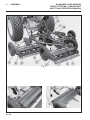
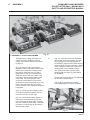
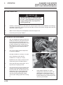
22114H-GB (rev.2)
®
Assembly, Safety and Operation Manual
Ransomes Gang Mower
Sportcutter Mk11, Magna Mk13
Product codes: LBMA171 Sportcutter Gang unit on pneumatic wheels
LBMA172 Sportcutter Gang unit on steel wheels
LJBA003 Sportcutter 3-unit on pneumatic wheels
LJBA004 Sportcutter 3-unit on steel wheels
LJBA011 Sportcutter Mounted 3-unit on pneumatic wheels
LJBA005 Sportcutter 5-unit on pneumatic wheels
LJBA006 Sportcutter 5-unit on steel wheels
LBMA174 Magna Gang unit on pneumatic wheels
LBMA173 Magna Gang unit on steel wheels.
LJBA015 Magna 3-unit on pneumatic wheels
LJBA016 Magna 3-unit on steel wheels
LJBA023 Magna Mounted 3-unit on pneumatic wheels
LJBA017 Magna 5-unit on pneumatic wheels
LJBA018 Magna 5-unit on steel wheels
WARNING: If incorrectly used this machine can cause severe
injury. Those who use and maintain this machine should be
trained in its proper use, warned of its dangers and should
read the entire manual before attempting to set up, operate,
adjust or service the machine.
GB
United
Kingdom
RJL 1C April 2013
© 2009, Ransomes Jacobsen Limited. All Rights Reserved
1
CONTENTS
CONTENTS
RANSOMES GANG MOWERS
SPORTCUTTER Mk11, MAGNA Mk13
SAFETY AND OPERATORS MANUAL
PAGE
2
2.1
2.2
INTRODUCTION
IMPORTANT .............................................................................................................2
PRODUCT IDENTIFICATION ...................................................................................2
3
3.1
3.2
3.3
3.4
3.5
3.6
3.7
3.8
3.9
SAFETY INSTRUCTIONS
OPERATING INSTRUCTIONS .................................................................................3
SAFETY SIGNS ........................................................................................................3
STARTING THE ENGINE .........................................................................................3
DRIVING THE MACHINE..........................................................................................3
TRANSPORTING ......................................................................................................3
LEAVING THE DRIVING POSITION ........................................................................4
SLOPES ....................................................................................................................4
BLOCKED CUTTING CYLINDERS ..........................................................................4
ADJUSTMENTS, LUBRICATION AND MAINTENANCE .........................................4
4
4.1
SPECIFICATIONS
CONFORMITY CERTIFICATES ...............................................................................6
5
5.1
5.2
5.3
5.4
DECALS AND UNIT SPECIFICATION
SAFETY DECALS.....................................................................................................8
COMPONENTS FOR TRAILED UNITS ....................................................................8
DIMENSIONS AND CUTTING PEFORMANCE .......................................................9
WEIGHTS ..................................................................................................................9
6
6.1
6.2
6.3
6.4
6.5
6.6
6.7
ASSEMBLY
SINGLE UNIT GANG MOWER ................................................................................10
3-UNIT GANG MOWER ...........................................................................................11
3-UNIT MOUNTED GANG MOWER ........................................................................12
5-UNIT GANG MOWER ...........................................................................................15
7-UNIT GANG MOWER ...........................................................................................16
9-UNIT GANG MOWER ...........................................................................................17
COUPLING GANG MOWERS TO POWER UNITS .................................................19
7
7.1
7.2
LUBRICATION
GEAR CASE, REAR ROLL, DRAWBAR ................................................................20
LUBRICATION CHART ...........................................................................................20
8
8.1
8.2
8.3
OPERATION
OPERATING PROCEDURE ....................................................................................21
DAILY INSPECTION ................................................................................................22
OPERATING THE GANG MOWERS .......................................................................22
9
9.1
MAINTENANCE
MAINTENANCE AND ADJUSTMENT .....................................................................23
10
10.1
TRANSPORTING
TRANSPORTING THE UNITS .................................................................................24
11
GUARANTEE/SALES & SERVICE .........................................................................25
en-3
2
INTRODUCTION
2.1
RANSOMES GANG MOWERS
SPORTCUTTER Mk11, MAGNA Mk13
SAFETY AND OPERATORS MANUAL
IMPORTANT
IMPORTANT: This is a precision machine and the service obtained from it depends on the way it is
operated and maintained.
This SAFETY AND OPERATORS MANUAL should be regarded as part of the machine. Suppliers of
both new and second-hand machines are advised to retain documentary evidence that this manual was
provided with the machine.
This machine is designed solely for use in customary grass cutting operations. Use in any other way is
considered as contrary to the intended use. Compliance with and strict adherence to the conditions of
operation, service and repair as specified by the manufacturer, also constitute essential elements of the
intended use.
Before attempting to operate this machine, ALL operators MUST read through this manual and make
themselves thoroughly conversant with Safety Instructions, controls, lubrication and maintenance.
Accident prevention regulations, all other generally recognized regulations on safety and occupational
medicine, and all road traffic regulations shall be observed at all times.
Any arbitrary modifications carried out on this machine may relieve the manufacturer of liability for any
resulting damage or injury.
2006/42/EC
These are the Original instructions verified by Ransomes Jacobsen Limited.
2.2
PRODUCT IDENTIFICATION
A
West Road
Ransomes Europark
Ipswich IP3 9TT
England
A
Kg
en-4
B
Kg
F
H
C
Kg
D
Kw
E
G
J
B
C
D
E
F
G
H
J
Maximum front axle load in Kg (for machines
being driven on the highway)
Gross weight (mass) in Kg
Maximum rear axle load in Kg (for machines
being driven on the highway)
Power in Kw
Date code
Machine type (Designation)
Product code
Product name
Serial number
3
SAFETY INSTRUCTIONS
RANSOMES GANG MOWERS
SPORTCUTTER Mk11, MAGNA Mk13
SAFETY AND OPERATORS MANUAL
This safety symbol indicates important safety
messages in this manual. When you see this
symbol, be alert to the possibility of injury, carefully
read the message that follows, and inform other
operators.
•
3.1 OPERATING INSTRUCTIONS
•
Ensure that the instructions in this book
are read and fully understood.
•
No person should be allowed to operate
this machine unless they are fully
acquainted with all the controls and the
safety procedures.
•
Never allow children or people unfamiliar
with these instructions to use this
machine. Local regulations may restrict
the age of the operator.
•
3.2 SAFETY SIGNS
•
It is essential all safety labels are kept
legible, if they are missing or illegible
they must be replaced. If any part of
the machine is replaced and it originally
carried a safety label, a new label must
be affixed to the replacement part.
New safety labels are obtainable from
Ransomes dealers.
•
3.3 STARTING THE ENGINE
•
Before starting the engine check that the
brakes are applied, drives are in neutral,
guards are in position and intact, and
bystanders are clear of the machine.
•
Do not run the engine in a building
without adequate ventilation.
3.4 DRIVING THE MACHINE
•
Before moving the machine, check to
ensure that all parts are in good working
order, paying particular attention to
brakes, tyres, steering and the security of
cutting blades.
•
Replace faulty silencers, mow only in
daylight or good artificial light
•
Always observe the Highway Code both
on and off the roads. Keep alert and
aware at all times. Watch out for traffic
when crossing or near roadways.
•
Stop the blades rotating before crossing
surfaces other than grass.
•
•
•
•
•
•
Remember that some people are deaf
or blind and that children and animals
can be unpredictable.
Keep travelling speeds low enough for
an emergency stop to be effective and
safe at all times, in any conditions.
Remove or avoid obstructions in the
area to be cut, thus reducing the
possibility of injury to yourself and/or
bystanders.
When reversing, take special care to
ensure that the area behind is clear of
obstructions and/or bystanders. DO
NOT carry passengers.
Keep in mind that the operator or user
is responsible for accidents or hazards
occurring to other people or their
property.
When the machine is to be parked,
stored or left unattended, lower the
cutting means unless the transport
locks are being used.
While mowing, always wear substantial
footwear and long trousers. Do not
operate the equipment when barefoot
or wearing open sandals.
Check the grass catcher frequently for
wear or deterioration. After striking a
foreign object. Inspect. the lawnmower
for damage and make repairs before
restarting and operating the equipment.
If the machine starts to vibrate
abnormally, check immediately.
3.5 TRANSPORTING
•
Ensure that the cutting units are
securely fastened in the transport
position. Do not transport with cutting
mechanism rotating.
•
Drive the machine with due
consideration of road and surface
conditions, inclines and local
undulations.
•
Sudden decelerating or braking can
cause the rear wheels to lift.
•
Remember that the stability of the rear
of the machine is reduced as the fuel is
used.
en-5
3
SAFETY INSTRUCTIONS
3.6 LEAVING THE DRIVING POSITION
•
Park the machine on level ground.
•
Before leaving the driving position, stop
the engine and make sure all moving
parts are stationary. Apply brakes and
disengage all drives. Remove the starter
key.
3.7 SLOPES
TAKE EXTRA CARE WHEN WORKING ON
SLOPES
•
Local undulations and sinkage will
change the general slope. Avoid ground
conditions which can cause the machine
to slide.
•
Keep machine speeds low on slopes and
during tight turns.
•
Sudden decelerating or braking can
cause the rear wheels to lift. Remember
there is no such thing as a “safe” slope.
•
Travel on grass slopes requires particular
care.
DO NOT USE ON SLOPES GREATER THAN 15°
IMPORTANT: When working on any slope set the
weight transfer, if fitted to its maximum (+) setting.
3.8 BLOCKED CUTTING CYLINDERS
•
Stop the engine and make sure all moving
parts are stationary.
•
Apply brakes and disengage all drives.
•
Release blockages with care. Keep all
parts of the body away from the cutting
edge. Beware of energy in the drive which
can cause rotation when the blockage is
released.
•
Keep other people away from the cutting
units as rotation of one cylinder can cause
the others to rotate.
3.9 ADJUSTMENTS, LUBRICATION AND
MAINTENANCE
•
Stop the engine and make sure all moving
parts are stationary.
•
Apply brakes and disengage all drives.
•
Read all the appropriate servicing
instructions.
•
Use only the replacement parts supplied by
the original manufacturer.
•
When adjusting the cutting cylinders take
care not to get hands and feet trapped when
rotating cylinders.
•
Make sure that other people are not touching
any cutting units, as rotation of one cylinder
can cause the others to rotate.
en-6
RANSOMES GANG MOWERS
SPORTCUTTER Mk11, MAGNA Mk13
SAFETY AND OPERATORS MANUAL
•
•
•
•
•
•
•
•
•
•
•
•
•
•
•
•
•
•
To reduce the fire hazard, keep the engine,
silencer and battery compartments free of
grass, leaves or excessive grease.
Replace worn or damaged parts for safety.
When working underneath lifted parts or
machines, make sure adequate support Is
provided.
Do not dismantle the machine without
releasing or restraining forces which can
cause parts to move suddenly.
Do not alter engine speed above maximum
quoted in Engine Specification. Do not
change the engine governor settings or
overspeed the engine. Operating the engine
at excessive speed may increase the hazard
of personal injury.
When refuelling, STOP THE ENGINE, DO
NOT SMOKE. Add fuel before starting the
engine, never add fuel while the engine is
running.
Use a funnel when pouring fuel from a can
into the tank.
Do not fill the fuel tank beyond the bottom of
the filler neck.
Replace all fuel tank and container caps
securely.
Store fuel in containers specifically designed
for this purpose.
Refuel outdoors only and do not smoke while
refuelling.
If fuel is spilled, do not attempt to start the
engine but move the machine away from
the area of spillage and avoid creating any
source of ignition until fuel vapours have
dissipated.
Allow the engine to cool before storing in any
enclosure.
Never store the equipment with fuel in the
tank inside a building where fumes may
reach an open flame or spark.
If the fuel tank has to be drained, this should
be done outdoors.
Do not spill fuel onto hot components.
When servicing batteries, DO NOT SMOKE,
and keep naked lights away.
Do not place any metal objects across the
terminals.
3
SAFETY INSTRUCTIONS
DANGER - Indicates an imminently hazardous
situation which, if not avoided, WILL result in death
or serious injury.
WARNING - Indicates a potentially hazardous
situation which, if not avoided, COULD result in
death or serious injury.
RANSOMES GANG MOWERS
SPORTCUTTER Mk11, MAGNA Mk13
SAFETY AND OPERATORS MANUAL
IMPORTANT: Transport speed is for highway
use only. Never select transport speed on
grass areas or uneven or unsurfaced roads or
tracks.
CAUTION - Indicates a potentially hazardous
situation which, if not avoided, MAY result in minor
or moderate injury and property damage. It may
also be used to alert against unsafe practices.
WARNING
Hydraulic Fluid escaping under pressure
can penetrate skin and do serious
damage. Immediate medical assistance
must be sought.
WARNING
Batteries produce explosive gases and
contain corrosive acid and supply levels
of electrical current high enough to cause
burns.
WARNING
DO NOT USE ON SLOPES GREATER THAN
en-7
4
CERTIFICATION
4.1
CONFORMITY CERTIFICATES
RANSOMES GANG MOWERS
SPORTCUTTER Mk11, MAGNA Mk13
SAFETY AND OPERATORS MANUAL
DECLARATION OF CONFORMITY ƒ ȾȿɄɅȺɊȺɐɂə ɁȺ ɋɔɈɌȼȿɌɋɌȼɂȿ ƒ PROHLÁŠENÍ O SHODċ ƒ
OVERENSSTEMMELSESERKLÆRING ƒ CONFORMITEITSVERKLARING ƒ VASTAVUSDEKLARATSIOON ƒ
VAATIMUSTENMUKAISUUSVAKUUTUS ƒ DECLARATION DE CONFORMITE ƒ KONFORMITÄTSERKLÄRUNG ƒ ǻǾȁȍȈǾ
ȈȊȂȂȅȇĭȍȈǾȈ ƒ MEGFELELėSÉGI NYILATKOZAT ƒ DICHIARAZIONE DI CONFORMITÀ ƒ ATBILSTƮBAS DEKLARƖCIJA ƒ
ATITIKTIES DEKLARACIJA ƒ DIKJARAZZJONI TAL-KONFORMITÀ ƒ DEKLARACJA ZGODNOĝCI ƒ DECLARAÇÃO DE
CONFORMIDADE ƒ DECLARAğIE DE CONFORMITATE ƒ VYHLÁSENIE O ZHODE ƒ IZJAVA O SKLADNOSTI ƒ DECLARACIÓN
DE CONFORMIDAD ƒ DEKLARATION OM ÖVERENSSTÄMMELSE ƒ SAMRÆMISYFIRLÝSING ƒ KONFORMITETSERKLÆRING
Business name and full address of the manufacturer ƒ Ɍɴɪɝɨɜɫɤɨ ɢɦɟ ɢ ɩɴɥɟɧ ɚɞɪɟɫ ɧɚ ɩɪɨɢɡɜɨɞɢɬɟɥɹ ƒ
Obchodní jméno a plná adresa výrobce ƒ Producentens firmanavn og fulde adresse ƒ Bedrijfsnaam en volledig adres van de fabrikant ƒ Tootja ärinimi ja täielik aadress ƒ
Valmistajan toiminimi ja täydellinen osoite ƒ Nom commercial et adresse complète du fabricant ƒ Firmenname und vollständige Adresse des Herstellers ƒ ǼʌȦȞȣȝȓĮ țĮȚ
IJĮȤȣįȡȠȝȚțȒ įȚİȪșȣȞıȘ țĮIJĮıțİȣĮıIJȒ ƒ A gyártó üzleti neve és teljes címe ƒ Ragione sociale e indirizzo completo del fabbricante ƒ UzƼƝmuma nosaukums un pilna
ražotƗja adrese ƒ Verslo pavadinimas ir pilnas gamintojo adresas ƒ Isem kummerƛjali u indirizz sƫiƫ tal-fabbrikant ƒ Nazwa firmy i pełny adres producenta ƒ Nome da
empresa e endereço completo do fabricante ƒ Denumirea comercială úi adresa completă a producătorului ƒ Obchodný názov a úplná adresa výrobcu ƒ Naziv podjetja in
polni naslov proizvajalca ƒ Nombre de la empresa y dirección completa del fabricante ƒ Tillverkarens företagsnamn och kompletta adress ƒ Fyrirtækisheiti og fullt
heimilisfang framleiðanda ƒ Firmanavn og full adresse for produsenten
Product Code ƒ Ʉɨɞ ɧɚ ɩɪɨɞɭɤɬɚ ƒ Kód výrobku ƒ Produktkode ƒ Productcode ƒ Toote kood ƒ Tuotekoodi ƒ Code produit ƒ Produktcode ƒ ȀȦįȚțȩȢ ʌȡȠȧȩȞIJȠȢ ƒ Termékkód ƒ
Codice prodotto ƒ Produkta kods ƒ Produkto kodas ƒ Kodiƛi tal-Prodott ƒ Kod produktu ƒ Código do Produto ƒ Cod produs ƒ Kód výrobku ƒ Oznaka proizvoda ƒ Código de
producto ƒ Produktkod ƒ Vörunúmer ƒ Produktkode
LBMA171, LBMA172, LBMA173, LBMA174
Machine Name ƒ ɇɚɢɦɟɧɨɜɚɧɢɟ ɧɚ ɦɚɲɢɧɚɬɚ ƒ Název stroje ƒ Maskinnavn ƒ Machinenaam ƒ Masina nimi ƒ Laitteen nimi ƒ Nom de la machine ƒ Maschinenbezeichnung ƒ
ȅȞȠȝĮıȓĮ ȝȘȤĮȞȒȝĮIJȠȢ ƒ Gépnév ƒ Denominazione della macchina ƒ IekƗrtas nosaukums ƒ Mašinos pavadinimas ƒ Isem tal-Magna ƒ Nazwa urządzenia ƒ Nome da
Máquina ƒ Numele echipamentului ƒ Názov stroja ƒ Naziv stroja ƒ Nombre de la máquina ƒ Maskinens namn ƒ Heiti tækis ƒ Maskinnavn
Ransomes Sportcutter Mk11
Ransomes Magna Mk13
Designation ƒ ɉɪɟɞɧɚɡɧɚɱɟɧɢɟ ƒ Oznaþení ƒ Betegnelse ƒ Benaming ƒ Nimetus ƒ Tyyppimerkintä ƒ Pažymơjimas ƒ
Bezeichnung ƒ ȋĮȡĮțIJȘȡȚıȝȩȢ ƒ Megnevezés ƒ Funzione ƒ ApzƯmƝjums ƒ Lithuanian ƒ Denominazzjoni ƒ Oznaczenie ƒ
Designação ƒ SpecificaĠie ƒ Oznaþenie ƒ Namen stroja ƒ Descripción ƒ Beteckning ƒ Merking ƒ Konstruksjon
Serial Number ƒ ɋɟɪɢɟɧ ɧɨɦɟɪ ƒ Sériové þíslo ƒ Serienummer ƒ Serienummer ƒ Seerianumber ƒ Valmistusnumero ƒ Numéro de série ƒ Seriennummer ƒ ȈİȚȡȚĮțȩȢ ĮȡȚșȝȩȢ ƒ
Sorozatszám ƒ Numero di serie ƒ SƝrijas numurs ƒ Serijos numeris ƒ Numru Serjali ƒ Numer seryjny ƒ Número de Série ƒ Număr de serie ƒ Sériové þíslo ƒ Serijska številka ƒ
Número de serie ƒ Serienummer ƒ Raðnúmer ƒ Serienummer
Towed Reel Mower
LW000299 - LW999999
LX000299 - LX999999
LY000299 - LY999999
LZ000299 - LZ999999
Engine ƒ Ⱦɜɢɝɚɬɟɥ ƒ Motor ƒ Motor ƒ Motor ƒ Mootor ƒ Moottori ƒ Moteur ƒ Motor ƒ ȂȘȤĮȞȒ ƒ Modulnév ƒ Motore ƒ DzinƝjs ƒ Variklis ƒ Saƫƫa Netta Installata ƒ Silnik ƒ Motor ƒ
Motor ƒ Motor ƒ Motor ƒ Motor ƒ Motor ƒ Vél ƒ Motor
Not Applicable
Net Installed Power ƒ ɇɟɬɧɚ ɢɧɫɬɚɥɢɪɚɧɚ ɦɨɳɧɨɫɬ ƒ ýistý instalovaný výkon ƒ Installeret nettoeffekt ƒ Netto geïnstalleerd vermogen ƒ Installeeritud netovõimsus ƒ
Asennettu nettoteho ƒ Puissance nominale nette ƒ Installierte Nettoleistung ƒ ȀĮșĮȡȒ İȖțĮIJİıIJȘȝȑȞȘ ȚıȤȪȢ ƒ Nettó beépített teljesítmény ƒ Potenza netta installata ƒ
ParedzƝtƗ tƯkla jauda ƒ Grynoji galia ƒ Wisa’ tal-Qtugƫ ƒ Moc zainstalowana netto ƒ Potência instalada ƒ Puterea instalată netă ƒ ýistý inštalovaný výkon ƒ Neto vgrajena moþ
ƒ Potencia instalada neta ƒ Nettoeffekt ƒ Nettóafl vélar ƒ Netto installert kraft
Not Applicable
Cutting Width ƒ ɒɢɪɨɱɢɧɚ ɧɚ ɪɹɡɚɧɟ ƒ ŠíĜka Ĝezu ƒ Skærebredde ƒ Maaibreedte ƒ Lõikelaius ƒ Leikkuuleveys ƒ Largeur de coupe ƒ Schnittbreite ƒ ȂȒțȠȢ ȝȚıȚȞȑȗĮȢ ƒ Vágási
szélesség ƒ Larghezza di taglio ƒ Griešanas platums ƒ Pjovimo plotis ƒ Tikkonforma mad-Direttivi ƒ SzerokoĞü ciĊcia ƒ Largura de Corte ƒ LăĠimea de tăiere ƒ Šírka záberu ƒ
Širina reza ƒ Anchura de corte ƒ Klippbredd ƒ Skurðbreidd ƒ Klippebredde
76 cm to 625 cm
Conforms to Directives ƒ ȼ ɫɴɨɬɜɟɬɫɬɜɢɟ ɫ ɞɢɪɟɤɬɢɜɢɬɟ ƒ SplĖuje podmínky smČrnic ƒ Er i overensstemmelse med direktiver ƒ Voldoet aan de richtlijnen ƒ Vastab
direktiividele ƒ Direktiivien mukainen ƒ Conforme aux directives ƒ Entspricht Richtlinien ƒ ǹțȠȜȠȣșȒıIJİ ʌȚıIJȐ IJȚȢ ȅįȘȖȓİȢ ƒ Megfelel az irányelveknek ƒ Conforme alle
Direttive ƒ Atbilst direktƯvƗm ƒ Atitinka direktyvǐ reikalavimus ƒ Valutazzjoni tal-Konformità ƒ Dyrektywy związane ƒ Cumpre as Directivas ƒ Respectă Directivele ƒ Je v
súlade so smernicami ƒ Skladnost z direktivami ƒ Cumple con las Directivas ƒ Uppfyller direktiv ƒ Samræmist tilskipunum ƒ I samsvar med direktiv
Conformity Assessment ƒ Ɉɰɟɧɤɚ ɡɚ ɫɴɨɬɜɟɬɫɬɜɢɟ ƒ Hodnocení plnČní podmínek ƒ Overensstemmelsesvurdering ƒ
Conformiteitsbeoordeling ƒ Vastavushindamine ƒ Vaatimustenmukaisuuden arviointi ƒ Evaluation de conformité ƒ
Konformitätsbeurteilung ƒ ǻȚĮʌȓıIJȦıȘ ȈȣȝȝȩȡijȦıȘȢ ƒ MegfelelĘség-értékelés ƒ Valutazione della conformità ƒ
AtbilstƯbas novƝrtƝjums ƒ Atitikties Ƴvertinimas ƒ Livell tal-Qawwa tal-ƪoss Imkejjel ƒ Ocena zgodnoĞci ƒ
Avaliação de Conformidade ƒ Evaluarea conformităĠii ƒ Vyhodnotenie zhodnosti ƒ Ocena skladnosti ƒ
Evaluación de conformidad ƒ Bedömning av överensstämmelse ƒ Samræmismat ƒ Konformitetsvurdering
en-8
Ransomes Jacobsen Limited
West Road, Ransomes Europark,
Ipswich, England, IP3 9TT
2006/42/EC
2006/42/EC Annex VIII
Measured Sound Power Level ƒ ɂɡɦɟɪɟɧɨ ɧɢɜɨ ɧɚ ɡɜɭɤɨɜɚ ɦɨɳɧɨɫɬ ƒ NamČĜený akustický výkon ƒ Målte lydstyrkeniveau ƒ Gemeten geluidsniveau ƒ Mõõdetud
helivõimsuse tase ƒ Mitattu äänitehotaso ƒ Niveau de puissance sonore mesuré ƒ Gemessener Schalldruckpegel ƒ ȈIJĮșȝȚıȝȑȞȠ İʌȓʌİįȠ ȘȤȘIJȚțȒȢ ȚıȤȪȠȢ ƒ Mért
hangteljesítményszint ƒ Livello di potenza sonora misurato ƒ IzmƝrƯtais skaƼas jaudas lƯmenis ƒ Išmatuotas garso stiprumo lygis ƒ Livell tal-Qawwa tal-ƪoss Iggarantit ƒ Moc
akustyczna mierzona ƒ Nível sonoro medido ƒ Nivelul măsurat al puterii acustice ƒ Nameraná hladina akustického výkonu ƒ Izmerjena raven zvoþne moþi ƒ Nivel de
potencia sonora medido ƒ Uppmätt ljudeffektsnivå ƒ Mælt hljóðaflsstig ƒ Målt lydeffektnivå
Not Applicable
Guaranteed Sound Power Level ƒ Ƚɚɪɚɧɬɢɪɚɧɨ ɧɢɜɨ ɧɚ ɡɜɭɤɨɜɚ ɦɨɳɧɨɫɬ ƒ Garantovaný akustický výkon ƒ Garanteret lydstyrkeniveau ƒ Gegarandeerd geluidsniveau ƒ
Garanteeritud helivõimsuse tase ƒ Taattu äänitehotaso ƒ Niveau de puissance sonore garanti ƒ Garantierter Schalldruckpegel ƒ ǼȖȖȣȘȝȑȞȠ İʌȓʌİįȠ ȘȤȘIJȚțȒȢ ȚıȤȪȠȢ ƒ
Szavatolt hangteljesítményszint ƒ Livello di potenza sonora garantito ƒ GarantƝtais skaƼas jaudas lƯmenis ƒ Garantuotas garso stiprumo lygis ƒ Livell tal-Qawwa tal-ƪoss
Iggarantit ƒ Moc akustyczna gwarantowana ƒ Nível sonoro farantido ƒ Nivelul garantat al puterii acustice ƒ Garantovaná hladina akustického výkonu ƒ Zajamþena raven
zvoþne moþi ƒ Nivel de potencia sonora garantizado ƒ Garanterad ljudeffektsnivå ƒ Hljóðaflsstig sem ábyrgð er tekin á ƒ Garanter lydeffektnivå
Not Applicable
Conformity Assessment Procedure (Noise) ƒ Ɉɰɟɧɤɚ ɡɚ ɫɴɨɬɜɟɬɫɬɜɢɟ ɧɚ ɩɪɨɰɟɞɭɪɚɬɚ (ɒɭɦ) ƒ
Postup hodnocení plnČní podmínek (hluk) ƒ Procedure for overensstemmelsesvurdering (Støj) ƒ
Procedure van de conformiteitsbeoordeling (geluid) ƒ Vastavushindamismenetlus (müra) ƒ
Vaatimustenmukaisuuden arviointimenettely (Melu) ƒ Procédure d’évaluation de conformité (bruit) ƒ
Konformitätsbeurteilungsverfahren (Geräusch) ƒ ǻȚĮįȚțĮıȓĮ ǹȟȚȠȜȩȖȘıȘȢ ȈȣȝȝȩȡijȦıȘȢ (ĬȩȡȣȕȠȢ) ƒ
MegfelelĘség-értékelési eljárás (Zaj) ƒ Procedura di valutazione della conformità (rumore) ƒ
AtbilstƯbas novƝrtƝjuma procednjra (troksnis) ƒ Atitikties Ƴvertinimo procednjra (garsas) ƒ
Proƛedura tal-Valutazzjoni tal-Konformità (ƪoss) ƒ Procedura oceny zgodnoĞci (poziom hałasu) ƒ
Processo de avaliação de conformidade (nível sonoro) Procedura de evaluare a conformităĠii (zgomot) ƒ
Postup vyhodnocovania zhodnosti (hluk) ƒ Postopek za ugotavljanje skladnosti (hrup) ƒ
Procedimiento de evaluación de conformidad (ruido) ƒ Procedur för bedömning av överensstämmelse (buller)
ƒ Samræmismatsaðferð (hávaði) ƒ Prosedyre for konformitetsvurdering (støy)
Not Applicable
UK Notified Body for 2000/14/EC ƒ ɇɨɬɢɮɢɰɢɪɚɧ ɨɪɝɚɧ ɜ Ɉɛɟɞɢɧɟɧɨɬɨ ɤɪɚɥɫɬɜɨ ɡɚ 2000/14/ȿɈ ƒ ÚĜad certifikovaný podle smČrnice þ. 2000/14/EC ƒ Det britiske
bemyndigede organ for 2001/14/EF ƒ Engels adviesorgaan voor 2000/14/EG ƒ Ühendkuningriigi teavitatud asutus direktiivi 2000/14/EÜ mõistes ƒ Direktiivin 2000/14/EY
mukainen ilmoitettu tarkastuslaitos Isossa-Britanniassa ƒ Organisme notifié concernant la directive 2000/14/CE ƒ Britische benannte Stelle für 2000/14/EG ƒ ȀȠȚȞȠʌȠȚȘȝȑȞȠȢ
ȅȡȖĮȞȚıȝȩȢ ǾȞȦȝȑȞȠȣ ǺĮıȚȜİȓȠȣ ȖȚĮ 2000/14/ǼȀ ƒ 2000/14/EK – egyesült királyságbeli bejelentett szervezet ƒ Organismo Notificato in GB per 2000/14/CE ƒ 2000/14/EK
AK reƧistrƝtƗ organizƗcija ƒ JK notifikuotosios Ƴstaigos 2000/14/EC ƒ Korp Notifikat tar-Renju Unit gƫal 2000/14/KE ƒ Dopuszczona jednostka badawcza w Wielkiej Brytanii
wg 2000/14/WE ƒ Entidade notificada no Reino Unido para 2000/14/CE ƒ Organism notificat în Marea Britanie pentru 2000/14/CE ƒ Notifikovaný orgán Spojeného
kráĐovstva pre smernicu 2000/14/ES ƒ Britanski priglašeni organ za 2000/14/ES ƒ Cuerpo notificado en el Reino Unido para 2000/14/CE ƒ Anmält organ för 2000/14/EG i
Storbritannien ƒ Tilkynntur aðili í Bretlandi fyrir 2000/14/EC ƒ Britisk teknisk for 2000/14/EF
Not Applicable
4
CERTIFICATION
RANSOMES GANG MOWERS
SPORTCUTTER Mk11, MAGNA Mk13
SAFETY AND OPERATORS MANUAL
Operator Ear Noise Level ƒ Ɉɩɟɪɚɬɨɪ ɧɚ ɧɢɜɨɬɨ ɧɚ ɞɨɥɨɜɢɦ ɨɬ ɭɯɨɬɨ ɲɭɦ ƒ
Hladina hluku v oblasti uší operátora ƒ Støjniveau i førers ørehøjde ƒ
Geluidsniveau oor bestuurder ƒ Müratase operaatori kõrvas ƒ
Melutaso käyttäjän korvan kohdalla ƒ Niveau de bruit à hauteur des oreilles de l’opérateur ƒ
Schallpegel am Bedienerohr ƒ ǼʌȓʌİįȠ șȠȡȪȕȠȣ ıİ ȜİȚIJȠȣȡȖȓĮ ƒ
A kezelĘ fülénél mért zajszint ƒ Livello di potenza sonora all’orecchio dell’operatore ƒ
TrokšƼa lƯmenis pie operatora auss ƒ Dirbanþiojo su mašina patiriamo triukšmo lygis ƒ
Livell tal-ƪoss fil-Widna tal-Operatur ƒ Dopuszczalny poziom hałasu dla operatora ƒ
Nível sonoro nos ouvidos do operador ƒ Nivelul zgomotului la urechea operatorului ƒ
Hladina hluku pôsobiaca na sluch operátora ƒ Raven hrupa pri ušesu upravljavca ƒ
Nivel sonoro en el oído del operador ƒ Ljudnivå vid förarens öra ƒ Hávaðastig fyrir stjórnanda ƒ Støynivå ved operatørens øre
Harmonised standards used ƒ ɂɡɩɨɥɡɜɚɧɢ ɯɚɪɦɨɧɢɡɢɪɚɧɢ ɫɬɚɧɞɚɪɬɢ ƒ Použité harmonizované normy ƒ Brugte harmoniserede standarder ƒ Gebruikte geharmoniseerde
standaards ƒ Kasutatud ühtlustatud standardid ƒ Käytetyt yhdenmukaistetut standardit ƒ Normes harmonisées utilisées ƒ Angewandte harmonisierte Normen ƒ
ǼȞĮȡȝȠȞȚıȝȑȞĮ ʌȡȩIJȣʌĮ ʌȠȣ ȤȡȘıȚȝȠʌȠȚȒșȘțĮȞ ƒ Harmonizált szabványok ƒ Standard armonizzati applicati ƒ Izmantotie saskaƼotie standarti ƒ Panaudoti suderinti
standartai ƒ Standards armonizzati uĪati ƒ Normy spójne powiązane ƒ Normas harmonizadas usadas ƒ Standardele armonizate utilizate ƒ Použité harmonizované normy ƒ
Uporabljeni usklajeni standardi ƒ Estándares armonizados utilizados ƒ Harmoniserade standarder som används
Technical standards and specifications used ƒ ɂɡɩɨɥɡɜɚɧɢ ɬɟɯɧɢɱɟɫɤɢ ɫɬɚɧɞɚɪɬɢ ɢ ɫɩɟɰɢɮɢɤɚɰɢɢ ƒ
Použité technické normy a specifikace ƒ Brugte tekniske standarder og specifikationer ƒ
Gebruikte technische standaards en specificaties ƒ Kasutatud tehnilised standardid ja spetsifikatsioonid ƒ
Käytetyt tekniset standardit ja eritelmät ƒ Spécifications et normes techniques utilisées ƒ
Angewandte technische Normen und Spezifikationen ƒ ȉİȤȞȚțȐ ʌȡȩIJȣʌĮ țĮȚ ʌȡȠįȚĮȖȡĮijȑȢ ʌȠȣ ȤȡȘıȚȝȠʌȠȚȒșȘțĮȞ ƒ MĦszaki szabványok és specifikációk ƒ Standard
tecnici e specifiche applicati ƒ
Izmantotie tehniskie standarti un specifikƗcijas ƒ Panaudoti techniniai standartai ir techninơ informacija ƒ
Standards u speƛifikazzjonijiet tekniƛi uĪati ƒ Normy i specyfikacje techniczne powiązane ƒ
Normas técnicas e especificações usadas ƒ Standardele tehnice úi specificaĠiile utilizate ƒ
Použité technické normy a špecifikácie ƒ Uporabljeni tehniþni standardi in specifikacije ƒ
Estándares y especificaciones técnicas utilizadas ƒ Tekniska standarder och specifikationer som används ƒ Samræmdir staðlar sem notaðir eru ƒ Benyttede harmoniserte
standarder
Not Applicable
BS EN 836-1997
Not Applicable
The place and date of the declaration ƒ Ɇɹɫɬɨ ɢ ɞɚɬɚ ɧɚ ɞɟɤɥɚɪɚɰɢɹɬɚ ƒ Místo a datum prohlášení ƒ Sted og dato for erklæringen ƒ Plaats en datum van de verklaring ƒ
Deklaratsiooni väljastamise koht ja kuupäev ƒ Vakuutuksen paikka ja päivämäärä ƒ Lieu et date de la déclaration ƒ Ort und Datum der Erklärung ƒ ȉȩʌȠȢ țĮȚ ȘȝİȡȠȝȘȞȓĮ
įȒȜȦıȘȢ ƒ A nyilatkozat kelte (hely és idĘ) ƒ Luogo e data della dichiarazione ƒ DeklarƗcijas vieta un datums ƒ Deklaracijos vieta ir data ƒ Il-post u d-data tad-dikjarazzjoni ƒ
Miejsce i data wystawienia deklaracji ƒ Local e data da declaração ƒ Locul úi data declaraĠiei ƒ Miesto a dátum vyhlásenia ƒ Kraj in datum izjave ƒ Lugar y fecha de la
declaración ƒ Plats och datum för deklarationen ƒ Tæknistaðlar og tæknilýsingar sem notaðar eru ƒ Benyttede tekniske standarder og spesifikasjoner ƒ Staður og dagsetning
yfirlýsingar ƒ Sted og dato for erklæringen
Ransomes Jacobsen Limited
West Road, Ransomes Europark,
Ipswich, England, IP3 9TT
1st September.2004
Signature of the person empowered to draw up the declaration on behalf of the manufacturer, holds the technical documentation and is authorised to compile the technical file, and who is
established in the Community.
ɉɨɞɩɢɫ ɧɚ ɱɨɜɟɤɚ, ɭɩɴɥɧɨɦɨɳɟɧ ɞɚ ɫɴɫɬɚɜɢ ɞɟɤɥɚɪɚɰɢɹɬɚ ɨɬ ɢɦɟɬɨ ɧɚ ɩɪɨɢɡɜɨɞɢɬɟɥɹ, ɤɨɣɬɨ ɩɨɞɞɴɪɠɚɳ
ɬɟɯɧɢɱɟɫɤɚɬɚ ɞɨɤɭɦɟɧɬɚɰɢɹ ɢ ɟ ɨɬɨɪɢɡɢɪɚɧ ɞɚ ɢɡɝɨɬɜɢ ɬɟɯɧɢɱɟɫɤɢɹ ɮɚɣɥ ɢ ɟ ɪɟɝɢɫɬɪɢɪɚɧ ɜ ɨɛɳɧɨɫɬɬɚ.
Podpis osoby oprávnČné sestavit prohlášení jménem výrobce, držet technickou dokumentaci a osoby oprávnČné
sestavit technické soubory a založené v rámci Evropského spoleþenství.
Underskrift af personen, der har fuldmagt til at udarbejde erklæringen på vegne af producenten, der er indehaver
af dokumentationen og er bemyndiget til at udarbejde den tekniske journal, og som er baseret i nærområdet.
Handtekening van de persoon die bevoegd is de verklaring namens de fabrikant te tekenen, de technische
documentatie bewaart en bevoegd is om het technische bestand samen te stellen, en die is gevestigd in het Woongebied.
Ühenduse registrisse kantud isiku allkiri, kes on volitatud tootja nimel deklaratsiooni koostama, kes omab tehnilist
dokumentatsiooni ja kellel on õigus koostada tehniline toimik.
Sen henkilön allekirjoitus
allekirjoitus, jolla on valmistajan valtuutus vakuutuksen laadintaan
laadintaan, jolla on hallussaan tekniset
asiakirjat, joka on valtuutettu laatimaan tekniset asiakirjat ja joka on sijoittautunut yhteisöön.
Signature de la personne habilitée à rédiger la déclaration au nom du fabricant, à détenir la documentation
technique, à compiler les fichiers techniques et qui est implantée dans la Communauté.
Unterschrift der Person, die berechtigt ist, die Erklärung im Namen des Herstellers abzugeben, die die
technischen Unterlagen aufbewahrt und berechtigt ist, die technischen Unterlagen zusammenzustellen,
und die in der Gemeinschaft niedergelassen ist.
ȊʌȠȖȡĮijȒ ĮIJȩȝȠȣ İȟȠȣıȚȠįȠIJȘȝȑȞȠȣ ȖȚĮ IJȘȞ ıȪȞIJĮȟȘ IJȘȢ įȒȜȦıȘȢ İț ȝȑȡȠȣȢ IJȠȣ țĮIJĮıțİȣĮıIJȒ, Ƞ ȠʌȠȓȠȢ
țĮIJȑȤİȚ IJȘȞ IJİȤȞȚțȒ ȑțșİıȘ țĮȚ ȑȤİȚ IJȘȞ İȟȠȣıȚȠįȩIJȘıȘ ȞĮ IJĮȟȚȞȠȝȒıİȚ IJȠȞ IJİȤȞȚțȩ ijȐțİȜȠ țĮȚ Ƞ ȠʌȠȓȠȢ İȓȞĮȚ įȚȠȡȚıȝȑȞȠȢ ıIJȘȞ ȀȠȚȞȩIJȘIJĮ.
A gyártó nevében meghatalmazott személy, akinek jogában áll módosítania a nyilatkozatot, a mĦszaki
dokumentációt Ęrzi, engedéllyel rendelkezik a mĦszaki fájl összeállításához, és aki a közösségben letelepedett személy.
Firma della persona autorizzata a redigere la dichiarazione a nome del fabbricante, in possesso Della
documentazione tecnica ed autorizzata a costituire il fascicolo tecnico, che deve essere stabilita nella Comunità.
TƗs personas paraksts, kura ir pilnvarota deklarƗcijas sastƗdƯšanai ražotƗja vƗrdƗ, kurai ir tehniskƗ
dokumentƗcija, kura ir pilnvarota sagatavot tehnisko reƧistru un kura ir apstiprinƗta KopienƗ.
Asmuo, kuris yra gana žinomas, kuriam gamintojas suteikơ Ƴgaliojimus sudaryti šią deklaraciją, ir kuris ją
pasirašơ, turi visą techninĊ informaciją ir yra Ƴgaliotas sudaryti techninơs informacijos dokumentą.
Il-firma tal-persuna awtorizzata li tfassal id-dikjarazzjoni f’isem il-fabbrikant, gƫandha d-dokumentazzjoni
teknika u hija awtorizzata li tikkompila l-fajl tekniku u li hija stabbilita fil-Komunità.
Podpis osoby upowaĪnionej do sporządzenia deklaracji w imieniu producenta, przechowującej dokumentacjĊ
techniczną, upowaĪnioną do stworzenia dokumentacji technicznej oraz wyznaczonej ds. wspólnotowych.
Assinatura da pessoa com poderes para emitir a declaração em nome do fabricante, que possui a documentação
técnica, que está autorizada a compilar o processo técnico e que está estabelecida na Comunidade.
Semnătura persoanei împuternicite să elaboreze declaraĠia în numele producătorului, care deĠine documentaĠia
tehnică, este autorizată să compileze dosarul tehnic úi este stabilită în Comunitate.
Podpis osoby poverenej vystavením vyhlásenia v mene výrobcu, ktorá má technickú dokumentáciu a je
oprávnená spracovaĢ technické podklady a ktorá je umiestnená v Spoloþenstve.
Podpis osebe, pooblašþene za izdelavo izjave v imenu proizvajalca, ki ima tehniþno dokumentacijo in lahko
sestavlja spis tehniþne dokumentacije, ter ima sedež v Skupnosti.
Firma de la persona responsable de la declaración en nombre del fabricante, que posee la documentación técnica
y está autorizada para recopilar el archivo técnico y que está establecido en la Comunidad.
Undertecknas av den som bemyndigad att upprätta deklarationen å tillverkarens vägnar, innehar den tekniska
dokumentationen och är bemyndigad att sammanställa den tekniska informationen och som är etablerad i
gemenskapen. Undirskrift aðilans sem hefur umboð til að gera yfirlýsinguna fyrir hönd framleiðandans, hefur undir höndum
tæknigögnin og hefur leyfi til að taka saman tækniskýrsluna, og er viðurkenndur innan evrópska efnahagssvæðisins.
Signaturen til personen som har fullmakt til å utferdige erklæringen på vegne av produsenten, er i besittelse av den
tekniske dokumentasjonen, har autorisasjon til å utarbeide den tekniske filen og som har tilhold i EU.
Tim Lansdell
Technical Director
1st January 2013
Ransomes Jacobsen Limited
West Road, Ransomes Europark,
Ipswich, England, IP3 9TT
Certificate Number ƒ ɇɨɦɟɪ ɧɚ ɫɟɪɬɢɮɢɤɚɬ ƒ ýíslo osvČdþení ƒ Certifikatnummer ƒ Certificaatnummer ƒ Sertifikaadi number ƒ Hyväksyntänumero ƒ Numéro de certificat ƒ
Bescheinigungsnummer ƒ ǹȡȚșȝȩȢ ȆȚıIJȠʌȠȚȘIJȚțȠȪ ƒ Hitelesítési szám ƒ Numero del certificato ƒ SertifikƗta numurs ƒ Sertifikato numeris ƒ Numru taƛ-ƚertifikat ƒ Numer
certyfikatu ƒ Número do Certificado ƒ Număr certificat ƒ ýíslo osvedþenia ƒ Številka certifikata ƒ Número de certificado ƒ Certifikatsnummer ƒ Númer skírteinis ƒ
Sertifikatnummer
4129431 (Rev.2)
en-9
5
DECALS AND UNIT SPECIFICATIONS
5.1 SAFETY DECALS AND INSTRUCTION
DECALS
A903489
Keep a Safe Distance from the
Machine.
A903494
Caution Rotating Blades.
5.2 COMPONENTS FOR TRAILED UNITS
Single unit Gang Mower
Cutting unit
Short draw bar (A)
Unit frame (C)
3-Unit Gang Mower
3 Cutting units
3 Short draw bars (A)
3 Unit frames (C)
2 Extension wings (D)
5-Unit Gang Mower
5 Cutting units
3 Short drawbars (A)
1 Long drawbar (B)
5 Unit frames (C)
2 Extensions wings (D)
1 Twin coupling frame (E)
7-Unit Gang Mower
7 Cutting units
4 Short drawbars (A)
2 Extension wings (D)
2 Twin coupling frames (E)
1 Single point 7 unit drawbar (F)
7 Unit frames (C)
9-Unit Gang Mower
9 Cutting units
6 Short drawbars (A)
2 Long drawbars (C)
9 Unit frames (B)
4 Extension Wings (D)
1 Twin coupling frame (E)
1 Expac 9 unit yoke (G)
en-10
RANSOMES GANG MOWERS
SPORTCUTTER Mk11, MAGNA Mk13
SAFETY AND OPERATORS MANUAL
5
DECALS AND UNIT SPECIFICATIONS
RANSOMES GANG MOWERS
SPORTCUTTER Mk11, MAGNA Mk13
SAFETY AND OPERATORS MANUAL
5.3 DIMENSIONS AND CUTTING
PERFORMANCE
Mounted
Gang
Mower
Model
Gang Mowers
Number
of Cutting
Units
1
3
5
7
9
3
Width of
Cut
76 cm
(2ft 6in)
2.1 m
(7ft 0in)
3.5 m
(11ft 6in)
3.27 m
(16ft 0in)
6.25 m
(20ft 6in)
2.1 m
(7ft 0in)
Overall
Width
1.22 m
(4ft 0in)
2.59 m
(8ft 6in)
3.96 m
(13ft 0in)
5.33 m
(17ft 6in)
6.70 m
(22ft oin)
2.59 m
(8ft 6in)
Overall
Length
81 cm
(2ft 8in)
2.59 m
(8ft 6In)
3.88 m
(12ft 9in)
3.27 m
(10ft 9in)
4.64 m
(15ft 3in)
2.59 m
(8ft 6in)
Transport
Width
-
-
-
-
-
2.43 m
(8ft 1in)
8 kph
(5 mph)
0.40
(1.0)
1.20
(3.0)
2.00
(5.0)
2.80
(7.0)
3.60
(9.0)
1.20
(3.0)
10 kph
(7 mph)
0.50
(1.4)
1.50
(4.2)
2.50
(7.0)
3.50
(9.8)
4.5
(12.6)
1.50
(4.2)
16 kph
(10 mph)
0.80
(2.0)
2.40
(6.0)
4.00
(10.0)
5.60
(14.0)
7.20
(18.0)
2.40
(6.0)
Initial
Pull
100 kg
(220 lb)
300 kg
(660 lb)
500 kg
(1100 lb)
700 kg
(1540 lb)
900 kg
(1980 lb)
300 kg
(660 lb)
In work
50 kg
(110 lb)
150 kg
(330 lb)
250 kg
(550 lb)
350 kg
(770 lb)
450 kg
(990 lb)
150 kg
(330 lb)
Hectares
(Acres)
Cut per
hour
Drawbar
Pull
5.4 WEIGHT
Mounted Gang Mower:
Frame:
176 kg
Individual Cutting Unit:
Sportcutter Mk 11: 115 kg
Magna Mk 13:
125 kg
en-11
6
ASSEMBLY
6.1
ASSEMBLY—SINGLE UNIT GANG MOWER
1.
(Fig. 1). Unscrew the pivot bolt (A) from
the centre of the unit frame. Insert the
lifting lever (B), spring first, into the rear
of the unit frame. The cranked handle can
face right or left. Check that the spring is
pointing downwards and hanging free,
then insert the pivot bolt (A), through the
hole in the lever and tighten. Do not overtighten as the lever must be free to move.
2.
Remove nuts and unscrew bolts (C) from
the unit frame stirrups. Position frame
over unit and lock the spring on to the
end of the arm which points forward from
the front axle of the cutting unit (Fig. 2),
then lower the frame on to the unit so
that the stirrups fit over the axle correctly.
Screw in and tighten bolts (C). Do not
over-tighten as too much pressure will
distort the stirrup and cause jamming.
3.
4.
en-12
RANSOMES GANG MOWERS
SPORTCUTTER Mk11, MAGNA Mk13
SAFETY AND OPERATORS MANUAL
Fit the lifting link (D) to the lifting lever
and lug (E), on the rear of the cutting unit
bottom block. The two nuts on the main
body of the link should be pointing away
from the cutting cylinder. The fixed short
loop at one end of the link should be
bolted to the lever, the sliding long loop
should be attached to the cutting unit. Do
not overtighten the bolts. When correctly
coupled the link should be free to pivot
either end, and be free to slide in and out.
Remove hitchpin (F) and with the
lubricating nipples on top insert the
drawbar into the front of the unit frame.
The slot must fit over the distance piece
which is already in position. Insert the
linchpin and secure with spring clip.
Fig 1
Fig 2
6
ASSEMBLY
RANSOMES GANG MOWERS
SPORTCUTTER Mk11, MAGNA Mk13
SAFETY AND OPERATORS MANUAL
Fig 3
6.2 ASSEMBLY—3-UNIT GANG MOWER
Assemble each cutting unit as single unit mower
instruction. Refer to page 10.
1.
(Fig. 3). To one of the cutting units bolt
on the extension wings (A) one each side
of the unit frame. Two long bolts (B) are
used at the rear which go through the
lugs of the extension wings and the unit
frame. Two short bolts (C) are used to
secure the front of the extension wings.
All must be tightened securely.
2.
(Fig. 4). From two of the short drawbars
take the universal couplings (A) and bolt
these into the towing points (B) on the
extension wings, ensuring that the bolts
are not overtightened as this will cause
distortion. The universal coupling must
be free to swivel. The lubricating nipples
must point upwards.
3.
(Fig. 3). Couple the two rear units to
the towing point on the extension wings
ensuring that the chains (D) hang below
the drawbars.
Fig 4
en-13
6
ASSEMBLY
RANSOMES GANG MOWERS
SPORTCUTTER Mk11, MAGNA Mk13
SAFETY AND OPERATORS MANUAL
Fig 5
Fig 6
en-14
Fig 7
6
ASSEMBLY
RANSOMES GANG MOWERS
SPORTCUTTER Mk11, MAGNA Mk13
SAFETY AND OPERATORS MANUAL
6.3 ASSEMBLY—3-UNIT MOUNTED GANG
MOWER
1.
(Fig. 5). Arrange the cutting units so that
the front two are in line alongside each
other, and the rear unit central. Attach the
hook end of the six diagonal stays (D) into
the lugs (A) on the stops of the cutting
units axle (B).
2
Fit stone guards to Sportcutter Units (Fig.
6) and on Magna Units (Fig. 7). The rear
of stone guard to be fitted before clamping
front of guard to main axle.
3.
(Fig. 5). Remove the six screws (C) from
the hinge brackets of the main frame. Lift
main frame over units and slide hinge
brackets over the centre of the axles,
insert screws and tighten.
Fig 8
Put end of diagonal stays (D) into lugs
forward of the main frame. Retain with
plain washers and split pins provided.
Remove lever pivot bolts (E) from main
frames, fit the lifting levers (F) spring first,
and replace pivot bolts. Hook springs (G)
on to arm protruding from front of cutting
unit axle.
Fit the lifting link (H) to the lifting lever
(F) and lug (I) on the rear of the cutting
unit bottom block. The two nuts on the
main body of the link should be pointing
away from the cutting cylinder. The fixed
short loop at one end of the link should be
bolted to the lever, the sliding long loop
should be attached to the cutting unit. Do
not overtighten the bolts. When correctly
coupled the link should be free to pivot
either end and be free to slide in and out.
Remove bolts (K) from lugs on the rear
diagonal tubes of the main frame and
fit the short ends of the lifting chain (J).
Check that chain is not twisted.
4.
Fig 9
(Fig. 8). Slide the ball joint of the two
bottom tractor arms over the end of the
lifting spindle (A) using the upper point
for Ford and British Leyland tractors, and
the lower ones for Massey Ferguson and
David Brown tractors. Insert the retaining
pins supplied with the tractor.
en-15
6
CONTROLS
Swing up the lifting frame and couple the
top link (B). The top hole and distance
piece is used with Ford and British
Leyland tractors. The top link on Massey
Ferguson and David Brown tractors is
fitted to the lower hole without a distance
piece.
5.
(Fig. 9). Reverse tractor to gang mower
and hitch up the draught eye (A) inserting
the pin from the top.
6.
(Fig. 5). Place long end of the lifting chain
over the pulley (L) and secure to lugs (M)
on main frame. Check that the spring (N)
is in position on the chain. It should be
positioned between the short chains 15
cm (6”) from the central ring.
7.
(Fig. 9). Set tractor drawbar using tractor
hydraulics until centre of lifting spindle
is 32 cm (12.5cm) from the ground, as
illustrated. Move tractor forward a little to
apply a load to the draught eye and check
that the swivel arms (B) are midway in
the guide plate, when the outfit is on
level ground. The swivel arm must not
foul the top or bottom of the guide plates
as in work this will result in poor ground
following and bending of components.
Adjust length of the top link so that the
lifting frame is vertical. Lock top link.
en-16
RANSOMES GANG MOWERS
SPORTCUTTER Mk11, MAGNA Mk13
SAFETY AND OPERATORS MANUAL
6
ASSEMBLY
6.4 ASSEMBLY—5-UNIT GANG MOWER
RANSOMES GANG MOWERS
SPORTCUTTER Mk11, MAGNA Mk13
SAFETY AND OPERATORS MANUAL
Fig 10
1.
Assemble three cutting units with unit
frames and short drawbars, and two
cutting units with unit frames only. Refer
to page 10.
2.
(Fig. 10). Place the two units without
drawbars side by side. Remove the hinge
plates (A) from the twin coupling frame
(B). Bolt an extension wing (C) and a
hinge plate to each unit. The extension
wings are fitted to the outer sides of the
unit frames and the hinge plates on the
inner sides. Long bolts (D) are used
on the two rear positions to secure the
extension wing and hinge plate to the unit
frame. Two short bolts (E) are used to
secure the front of the extension wing and
hinge plate.
3.
(Fig. 11). Locate the twin coupling frame
on to the hinge plates between the two
front units and secure with clips.
4
(Fig. 10). With the lubricating nipples on
top insert the long drawbar (J) into the
front of the twin coupling frame. The slot
fits over a distance piece which is already
in position. Insert the pin (K) and secure
with the spring clips.
5.
(Fig. 10). From the three short drawbars
remove the universal couplings (F). Bolt
two couplings into the towing points on
the extension wings and the other into the
towing point at the rear of the twin coupling
frame. Couple the three rear units to the
towing points on the extension wings
and centre of the twin coupling frame,
ensuring that the chains (L) hang below
the drawbars.
Ensure that the bolts are not overtightened
as this will cause distortion.
The coupling must be free to swivel.
Lubricating nipples must point upwards.
Fig 11
en-17
6
ASSEMBLY
6.5 ASSEMBLY—7-UNIT GANG MOWER
1.
Assemble four cutting units with unit
frames and short drawbar and three
cutting units with unit frames only. Refer
to page 10.
2.
Place the three units without drawbars
side by side.
3
4.
5
6.
en-18
RANSOMES GANG MOWERS
SPORTCUTTER Mk11, MAGNA Mk13
SAFETY AND OPERATORS MANUAL
Fig 12
(Fig. 12). Remove hinge plates (A) from
the coupling frames.
Bolt an extension wing (B) and a hinge
plate (A) to the outer units. The extension
wings are fitted to the outer sides of the
unit frames and the hinge plates on the
inner sides. Long bolts (C) are used
on the two rear positions to secure the
extension wing and hinge plate to the unit
frame.
Two short bolts (D) are used to secure
the front of the extension wing and hinge
plate.
Bolt hinge plates on both sides of the
centre unit frame with long bolts at the
rear and short bolts at the front and
tighten securely.
Locate the twin coupling frames on to the
hinge plates between the three front units
and secure with clips. From the four short
drawbars remove the universal couplings.
Bolt two couplings into the towing points
on the extension wings and the other one
into the towing point at the rear of the twin
7.
coupling frames. Couple the four rear units
to the towing point on the extension wings
and centre of the twin coupling frames,
ensuring that the chains hang below the
drawbars. Ensure that the bolts are not
overtightened, as this will cause distortion.
The coupling must be free to swivel. The
lubricating nipples must point upwards.
(Fig. 13). Fit the seven unit drawbar (A)
into the front of the twin coupling frame
using the pins provided and ensuring
that the lubricating nipples are pointing
upwards. From the short drawbars remove
the universal couplings (E) (Fig. 12). Bolt
these couplings into the towing hitches on
the extension wings and the towing points
at the rear of the twin coupling frames.
Ensure that the bolts are not overtightened
as this will cause distortion. The couplings
must be free to swivel. The lubricating
nipples must point upwards.
Fig 13
ASSEMBLY
RANSOMES GANG MOWERS
SPORTCUTTER Mk11, MAGNA Mk13
SAFETY AND OPERATORS MANUAL
Fig 14
6
en-19
6
ASSEMBLY
RANSOMES GANG MOWERS
SPORTCUTTER Mk11, MAGNA Mk13
SAFETY AND OPERATORS MANUAL
6.6 ASSEMBLY—9-UNIT GANG MOWER
Assemble five cutting units with unit frames and
and short drawbars, two cutting units
with unit frames and long drawbars, two
cutting units with unit frames only. Refer
to page 10.
2.
(Fig. 14). To two of the units fitted
with unit frames and long drawbars fit
extension wings (A) to both sides using
long bolts to secure the rear and short
bolts at the front.
3.
Position the two units without drawbars
side by side. Remove the hinge plates
(B) from the twin coupling frame and bolt
these to the inner sides of the unit frame
using long bolts at the rear and short
bolts at the front. Locate twin coupling
frame (C) on to the hinge plates and
secure with clips. Fit short drawbar to
front of twin coupling frame. Remove
hitch pin and with the lubricating nipples
on top insert the drawbar into the front
of the unit frame. The slot must fit over
the distance piece which is already in
position. Insert the hitch pin and secure
with spring clip.
4.
5.
(Fig. 15). Fit centre tube (A) of the yoke
to the main tube (B). Check that the stand
(C) and hook (D) are pointing downwards
and secure with the bolts, nuts and
washers provided. Next fit the two outer
members (E) to the front of the centre
tube and to the outer face of the brackets
on the end of the main tube (Fig. 16).
Tighten all bolts securely. Fit wheels (F)
to the main tube.
Remove the universal couplings from all
drawbars and bolt these to the towing
points on the yoke, twin coupling frames
and extension wings.
Ensure that the bolts are not
overtightened as this will cause distortion.
Universal couplings must be free to
swivel. Lubricating nipples must point
upwards.
(a)
en-20
Couple the two units fitted with twin coupling frame to the towing hitch at the centre
of the yoke.
Fig 15
Fig 16
(b)
Couple one unit fitted with a short drawbar
to the towing point at the rear of the twin
coupling frame.
(c)
Couple two units fitted with long drawbars
to the towing points at each end of the
yoke.
(d)
Couple four units fitted with short drawbars
to the towing points on the extension
wings.
Ensure when securing drawbars to towing
hitches that the chain attached to the hitch
pins hang below the drawbars.
6
ASSEMBLY
RANSOMES GANG MOWERS
SPORTCUTTER Mk11, MAGNA Mk13
SAFETY AND OPERATORS MANUAL
6.7 COUPLING THE GANG MOWERS
TO A TRACTOR
(Fig. 17). The tractor drawbar must be fixed. If it
is a swivelling type, a bracket (A) must be fitted to
prevent it from tipping up or down. Stabilisers must
be fitted to the lower links of the tractor to prevent
movement from side to side. Bolt the tractor hitch
(B) to the tractor drawbar and tighten securely.
TRACTOR TOWING HITCH FOR 1, 3, 5 AND 7
UNIT TRAILED GANG MOWER (Fig. 17)
With the lubricating nipples on top insert the
universal coupling (C) and secure with bolt. If the
space between the two plates is too wide for the
universal coupling fit plain washers (D) as required.
The long bolt which holds the universal coupling
between the plates should be inserted from the top.
It must not be overtightened as this will squeeze
in the plates. The universal coupling must be free
to swivel. Couple the drawbar to the universal
coupling with the hitch pin and clip. The chain at
this point must hang freely underneath the drawbar
to prevent damage.
TRACTOR TOWING HITCH FOR 9 UNIT
TRAILED GANG MOWER
The tractor loop (A, Fig. 18) is bolted to the centre
of the tractor drawbar. The yoke ~s supported
by the adjustable stand (A, Fig. 19). The tractor
can then be reversed so that the tractor loop is
beneath the hook on the yoke. The foot rest is then
retracted allowing the hook to locate in the tractor
loop. A safety catch (B) must be raised and held in
position by the drop pin.
ALIGNMENT AND ADJUSTMENTS
(Fig. 20). With the tractor on level ground and the
drawbar set at 15” from the ground check that the
top of the unit frame is horizontal. If it is not it can
be adjusted by withdrawing the bolts from the front
of the unit frame (A). This will allow the front of the
unit frame to be raised or lowered to give correct
level. The bolt should be replaced in the nearest
hole but check that the distance piece inside the
unit frame is in position before securing.
Adjust the rear roller of the cutting unit to give the
height of cut you require, then check the position
of the lifting link (B). The sliding part of the link
should be in a mid way position, i.e. half the link
shoud be outside the square main body and half
inside, ensuring maximum float of the cutting unit
over ground undulations. The lifting lever can be
moved to any one of three positions to give this
adjustment. The lever is secured by a pin (C) which
should be placed into the nearest hole when the
Fig 17
Fig 18
Fig 19
Fig 20
link is in its correct position.
If the height of cut is altered you must check the
position of the lifting link and adjust as necessary.
The chain (D) at this point should be over the lever.
The outfit as far as assembly and alignment is concerned is now ready for use but before putting it
into work it must be serviced.
en-21
7
LUBRICATION
RANSOMES GANG MOWERS
SPORTCUTTER Mk11, MAGNA Mk13
SAFETY AND OPERATORS MANUAL
7.1 LUBRICATION
GEAR CASE
Machines are despatched without oil in the
gearcases which must be filled to the correct level
before use. (Fig. 21). Correct lubrication of the gear
box is essential for long life and good performance.
Each gear box—there is one on the left and one on
the right of the cutting unit—must be provided with
oil up to the level of the oil level plug (A). Remove
this plug to check oil level. If necessary remove
filter plug (B) and top up until oil appears from level
plug hole. Replace the oil level plug ensuring that
the fibre washer is in position. Never top up without
removing level plug. The correct grade of oil for
gear boxes is SAE 140. If the unit is used with
other manufacturers frame work which tilts the unit
on end the gear box should be lubricated with non
tracking grease to prevent leakage. Check level
monthly.
Fig 21
REAR ROLL
(Fig. 22). There are two lubricating nipples (A) in
the rear roller carriages which must be lubricated
weekly using oil in the lubricating gun.
DRAWBAR
Each drawbar and universal coupling has four
nipples
(B and C), which should be lubricated weekly.
Fig 22
Do not lubricate the sliding parts or attachment
points of the lifting links (D). Oil on these points will
collect dirt and grit which will accelerate wear.
7.2 LUBRICATION CHART
Gear Boxes
Check and Top Up
Monthly
SAE 140 Oil or
Retinax 'G' Semi Fluid
Grease
Rear Roll Carridges
Lubricate
Weekly
Grease
Drawbar
Lubricate
Weekly
Grease
Universal Joint
Lubricate
Weekly
Grease
en-22
8
OPERATION
RANSOMES GANG MOWERS
SPORTCUTTER Mk11, MAGNA Mk13
SAFETY AND OPERATORS MANUAL
8.1 OPERATING PROCEDURE
CAUTION
To help prevent injury, always wear safety
glasses, leather work shoes or boots, a
hard hat and ear protection.
1.
Under no circumstances should the engine be started without the operator seated on the tractor.
2.
Do not operate tractor or attachments with loose, damaged or missing components. Whenever
possible mow when grass is dry
3.
First mow in a test area to become thoroughly familiar with the operation of the tractor and control
levers.
Note:
To prevent damage to the reel and bottom blade never operate the reels when they are not
cutting grass. Excessive friction and heat will develop between the bottom blade and reel
and damage the cutting edge.
4.
Study the area to determine the best and safest operating procedure. Consider the height of
the grass, type of terrain, and condition of the surface. Each condition will require certain
adjustments or precautions.
5.
Never direct discharge of material toward bystanders, nor allow anyone near the machine while in
operation. The owner/operator is responsible for injuries inflicted to bystanders and/or damage to
their property.
CAUTION
Pick up all debris you can f nd before
mowing. Enter a new area cautiously
Always operate at speeds that allow you to
have complete control of the tractor
6.
Use discretion when mowing near gravel areas (roadway, parking areas, cart paths, etc.). Stones
discharged from the implement may cause serious injuries to bystanders and/or damage the
equipment.
7.
Stop and inspect the equipment for damage immediately after striking an obstruction or if the
machine begins to vibrate abnormally. Have the equipment repaired before resuming operation.
WARNING
Before you clean, adjust, or repair this
equipment, always disengage all drives,
lower implements to the ground, engage
parking brake, stop engine and remove key
from ignition switch to prevent injuries.
en-23
8
OPERATION
RANSOMES GANG MOWERS
SPORTCUTTER Mk11, MAGNA Mk13
SAFETY AND OPERATORS MANUAL
8.2 DAILY INSPECTION
CAUTION
The daily inspection should be performed
only when the engine is off and all f uids
are cold. Lower implements to the ground,
engage parking brake, stop engine and
remove ignition key.
1.
Perform a visual inspection of the entire unit, look for signs of wear, loose hardwear and missing or
damaged components. Check for fuel and oil leaks to ensure connections are tight and hoses and
tubes are in good condition.
2.
Make sure all cutting units are adjusted to the same height of cut.
3.
Check all tyres for proper inflation.
8.3 OPERATING THE GANG MOWERS
1.
(Fig. 23). Engage the cutting unit drive by
pulling out and turning the gear selectors
(A) on each side of the cutting unit to a
vertical position and ensure that the cross
pin (B) is located in the vertical groove.
Both selectors must be in drive otherwise
overloading and also wheel slip will be
caused.
2.
The correct towing speed is dependent
on ground conditions.
Fig 23
Average conditions 6—8 kph (4—5 mph).
Good, relatively smooth ground
conditions 9—11 kph (6—7 mph).
Speeds of up to 16 kph (10 mph) can be
used where ground conditions permit.
3.
If the rear rolls bounce slow down. It is a
sign that you are going too fast.
4.
The speed of the machine should be fast
enough to give a good grass throw from
the rear of the unit. This will ensure even
distribution of the cut grass behind the
machine and give a good appearance
and also prevent grass being carried
round by the cutting cylinder and choking
it.
en-24
Fig 24
5.
Avoid rapid acceleration or violent
engagement of the tractor clutch. Pull
away gently to avoid shocks to the
transmission, this will help considerably
towards obtaining long life and good service from your machine.
9
MAINTENANCE
RANSOMES GANG MOWERS
SPORTCUTTER Mk11, MAGNA Mk13
SAFETY AND OPERATORS MANUAL
9.1 MAINTENANCE
CUTTING CYLINDER ADJUSTMENT
(Fig. 24). Before use, check the cutting cylinder
adjustment, which must be set correctly and locked.
To do this, check the adjustment by revolving the
cutting cylinder manually and testing with thin paper,
newspaper will do. If the paper is not cut cleanly,
unlock the bottom block locks (A) by turning them
clockwise. Next turn the nut (B) on top of the bracket
clockwise a little at a time until the cutting cylinder
will cut paper cleanly. The cutting cylinder MUST
spin freely. Retighten the bottom block lock securely,
adjusting nut (B) as necessary to maintain correct
setting. The correct setting of the unit is essential for
good performance and long life.
HEIGHT OF CUT ADJUSTMENT
(Fig. 25). The machine is supplied to give a medium
cut. To alter the height of cut remove the bolts (A)
which secure the rear roll carriages and move the carriages up or down as required. Replace and securely
tighten the bolts.
Note The nuts (B) need not be slackened to do this.
Caution A machine should never be used with the
bottom blade pressing on the ground as the cutting
cylinder may be damaged by the bottom blade being
forced upwards, also the wear is greater and the
machine will be harder to work.
Fig 25
If the machine is washed down use low pressure
only, otherwise water will be forced into the bearings
and housings and cause corrosion which will shorten
the working life.
CAUTION
Use only genuine parts supplied from your
approved Textron Turf Care and Specialty
Products Dealer, when maintaining and
repairing your equipment.
TYRE PRESSURE
The tyre pressure should be maintained at 1.05 kg/
cm2 (15 psi).
SCRAPER
Scrapers are intended for use in wet, muddy conditions and should be adjusted so that they are just clear
of the rear roll. They must never be allowed to contact
the rear roll.
REMOVING THE CUTUING CYLINDER
(Fig. 30). The cutting cylinder can be removed without
dismantling the remainder of the machine. Remove
the small cover (A) and gasket from the main gear
cover. Take out the four screws securing the cylinder
housing (B) to the side frames. The cylinder can
now be lifted out by a steady upward pull applied
simultaneously to each end of the cylinder.
GENERAL MAINTENANCE AND STORAGE
After use, it is recommended that you clean off the
machine, brush or wipe oil on to the cutters. A few
turns in reverse when you are doing this will scrape oil
on to the edge of the bottom blade.
en-25
10
TRANSPORTING
RANSOMES GANG MOWERS
SPORTCUTTER Mk11, MAGNA Mk13
SAFETY AND OPERATORS MANUAL
10.1 TRANSPORTING
TRAILED GANG UNITS
1.
2
When moving from site to site the cutting
cylinders must be out of gear, but this
must not be done while the machine is in
motion.
(Fig. 26). When trailed gang mowers are
moved along paths or roads the rear rolls
must be raised clear of the ground by
locking the lifting lever in the top hole (A)
of the unit frame.
Fig 26
TRANSPORTING TRAILED GANG MOWERS IN
TRAILERS AND TRUCKS
(Fig. 27). All drawbars and coupling frames can
be quickly removed and the frame dismantled into
easily transportable units. The lifting levers must be
anchored in the bottom position (A) and the nose
of the rear unit pinned into the top lifting lever hole
(B) of the front unit. By this method a three unit or
five unit mower can be coupled nose to tail and
winched up to a truck or trailer.
The unit fitted with extension wings must be the
last of the series. When close packing five unit and
seven unit mowers which include two unit frames
fited with one extension wing each, it is necessary
to use the trailing hitch (C). This should be fitted to
the lifting hole (D) of the second last unit frame and
the nose of the last frame pinned through the hole
in the hitch (E). The lifting lever of the last frame
should be allowed to float.
Fig 27
before putting the machine into work. It is necessary,
however, to drive the tractor forward to enable the
wing units to take up their working position before
replacing the locking pins.
MOUNTED TRIPLE MOWER
For road transport the machine must be raised and
locked for safety to reduce the overall width of the
machine to comply with the Ministry of Transport
Regulations.
1.
(Fig. 28). Remove locking pins (A) from
hole in brackets (B) at both sides of the
machine.
2.
(Fig. 29). Attach check chains (A) to main
axle of outer cutting units.
3.
Lift machine by operating tractor hydraulic
lift.
4.
(Fig. 28). Replace locking pins (A) in
brackets (B) at both sides of the machine.
After transporting, the above procedure is reversed
en-26
Fig 28
Fig 29
11
GUARANTEE / SALES & SERVICE
RANSOMES GANG MOWERS
SPORTCUTTER Mk11, MAGNA Mk13
SAFETY AND OPERATORS MANUAL
GUARANTEE
We GUARANTEE that should any defect in workmanship or material occur in the
goods within TWO YEARS or two thousand hours (on models equipped with hour
meters), or whichever occurs f rst.
Exception to this warranty will be Aeration products, which are covered for a period
of TWO-YEARS or f ve hundred hours (on models equipped with hour meters) or
whichever occurs f rst.
We will repair, or at our option, replace the defective part without making any charge
for labour or for materials, provided that the claim under this guarantee is made
through an authorised dealer and that the defective part shall, if we so request, be
returned to us or to the dealer.
This guarantee is in addition to, and does not exclude, any condition or warranty
implied by law, except that we accept no liability in respect of used/second-hand
goods, or in respect of defects which in our opinion are in any way or to any extent
attributable to misuse, lack of reasonable care or ordinary wear and tear, or to
the f tting of spares, replacements, or extra components which are not supplied
or approved by us for the purpose. The use of non-recommended oil or lubricant
nullif es the guarantee.
Damage through transport or normal wear does not come under the guarantee.
The warranty is extended to the original purchaser only and is not transferable to
subsequent owners. The warranty period begins on the date the product is delivered
to the end user (customer), unless otherwise agreed with the manufacturer. At the
end of the f rst year the owner must have the product serviced by an authorised
dealer to be eligible for the second year of warranty coverage.
SALES & SERVICE
A network of authorised Sales and Service dealers has been established and these
details are available from your supplier.
When service attention, or spares, are required for the machine, within or after
the guarantee period your supplier or any authorised dealer should be contacted.
Always quote the registered number of the machine.
If any damage is apparent when delivery is made, report the details at once to the
supplier of the machine.
en-27
Europe & Rest of The World Except North & South America
Ransomes Jacobsen Limited
West Road, Ransomes Europark, Ipswich, IP3 9TT
English Company Registration No. 1070731
www.ransomesjacobsen.com
North & South America
Jacobsen, A Textron Company
11108 Quality Drive, Charlotte,
NC 28273, USA
www.Jacobsen.com