1
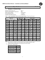
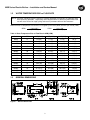
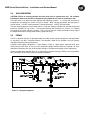
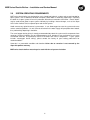
INSTALLATION AND SERVICE MANUAL
MINI-STAR® ELECTRIC BOILER
Models 6MSE to 54MSE for Hydronic Heating
6 kW to 54 kW, 208 Vac to 600 Vac, Single or Three Phase
WARNING
Risk of electric shock. This unit may be connected to more than one
electrical circuit. Turn off all electrical supply circuits before servicing.
IMPORTANT
• The boiler must be installed in accordance with all applicable national, provincial/state,
and local codes, laws, regulations, and ordinances.
• This manual must be left with owner and should be located adjacent to the boiler for
reference.
• Ensure boiler is full of water before turning on electricity. Elements will burn out
immediately without water in the boiler.
• A boiler installed above radiation level (or as required by an Authority having
jurisdiction) must be provided with a low-water cut-off device at the time of boiler
installation.
• Overcurrent protection between the power supply and the boiler must be provided in
accordance with the related national and/or local codes.
• Always ensure power is turned off before servicing.
• Electrical wiring or internal controls must be serviced by a qualified electrician. Any
adjustment of the internal controls must be performed by a qualified service
technician.
Post these instructions in a visible place.
DATE OF INSTALLATION :
INSTALLED BY :
PHONE :
Featuring the
BC-1 Controller
with Outdoor Reset and DHW Override
Manufactured by
Allied Engineering Company
Division of E-Z-Rect Manufacturing Ltd.
Manufacturers of Gas and Electric Boilers, Heat Exchangers, Electric Boosters, Indirect Tanks
94 Riverside Drive, North Vancouver, B.C. V7H 2M6 • Telephone 604-929-1214 • www.alliedboilers.com
Branches: Calgary • Edmonton • Toronto • Denver
PN4330651
(OPTIONAL)
MSE Series Electric Boilers – Installation and Service Manual
Dimensions and Specifications
1.1
Section 1
TECHNICAL SPECIFICATIONS
Maximum Operating Pressure:
Maximum Operating Water Temperature:
Water Capacity in Boiler:
Inlet and Outlet Pipe Size:
Controller Pump Switch Capacity:
90 p.s.i.
210ºF
6.6 US Gallons
1 1/4” NPT
5A Maximum
Table 1: Super Hot MSE Series Electric Boiler Specifications. (Flange Type Elements)
Super Hot
MSE Series Electric Boilers
Single Phase
Three Phase
208 Vac
240 Vac
208 Vac
240 Vac
480 Vac
600 Vac
Model
kW
Btu/Hr
Amp
Amp
Amp
Amp
Amp
Amp
6MSE
6
20,474
28.9
25.0
16.7
14.4
7.2
5.8
9MSE
9
30,708
43.3
37.5
25.0
21.6
10.8
8.7
12MSE
12
40,848
57.7
50.0
33.3
28.8
14.4
11.5
15MSE
15
51,185
72.1
62.5
41.6
36.0
18.0
14.4
18MSE
18
61,422
86.5
75.0
54.6*
47.3*
23.7*
18.9*
20MSE
20
68,240
96.2
84.3
63.6*
55.1*
27.6*
22.0*
24MSE
24
81,895
115
100
66.5
57.7
28.8
23.1
27MSE
27
92,124
130
113
74.9
64.9
32.4
26.0
30MSE
30
102,369
144
125
83.2
72.1
36.0
28.8
34MSE
34
116,008
164
142
100*
87.0*
43.5*
34.8*
38MSE
38
129,656
183
158
118*
102*
50.5*
40.4*
42MSE
42
143,304
202
175
116
101
50.5
40.4
45MSE
45
153,540
216
188
125
108
57.7*
46.2*
48MSE
48
163,776
231
200
138*
119*
59.6*
47.7*
54MSE
54
184,248
260
225
150
130
64.9
52.0
Note:
1.
2.
3.
Other models of the MSE Series Electric Boiler may be available subject to inquiry.
* Delta connection (unbalanced load) amperage of high leg indicated.
Approximate shipping weights:
Model
Ŧ
Weight
6MSE & 9MSE
114 lb
12MSE to 18MSE
116 lb
20MSE & 24MSE
118 lb
27MSE to 38MSE
122 lb
42MSE to 54MSE
126 lb
Ŧ
Add 45 lb for package models
2
MSE Series Electric Boilers – Installation and Service Manual
1.2
WATER TEMPERATURE RISE vs FLOW RATE
NOTE: The boiler should be properly sized for its heating application and maintain an adequate water
flow rate during operation. Significantly oversizing the boiler or decreasing boiler water flow
rate will cause excessive stage cycling and result in premature failure of the contactors.
Water flow rate vs temperature rise formulas in US gallons per minute (GPM) and liters per minute (LPM):
6.94 x kW
Temp. Rise (°F)
GPM =
LPM =
14.6 x kW
Temp. Rise (°C)
Table 2: Water Temperature Rise vs Flow Rate in GPM (LPM)
1.3
Model
KW
10°°F (5.6°°C)
20°°F (11°°C)
30°°F (17°°C)
40°°F (22°°C)
6MSE
6
4.2 (16)
2.1 (8)
1.4 (5)
1.0 (4)
9MSE
9
6.2 (23)
3.1 (12)
2.1 (8)
1.6 (6)
12MSE
12
8.3 (31)
4.2 (16)
2.8 (10)
2.1 (8)
15MSE
15
10.4 (39)
5.2 (20)
3.5 (13)
2.6 (10)
18MSE
18
12.5 (47)
6.2 (24)
4.2 (15)
3.1 (12)
20MSE
20
13.9 (52)
6.9 (27)
4.6 (17)
3.5 (13)
24MSE
24
16.6 (63)
8.3 (32)
5.5 (21)
4.2 (16)
27MSE
27
18.7 (70)
9.4 (36)
6.2 (23)
4.7 (18)
30MSE
30
20.8 (78)
10.4 (40)
6.9 (26)
5.2 (20)
34MSE
34
23.6 (89)
11.8 (45)
7.9 (29)
5.9 (23)
38MSE
38
26.4 (99)
13.2 (50)
8.8 (33)
6.6 (25)
42MSE
42
29.1 (109)
14.6 (56)
9.7 (36)
7.3 (28)
45MSE
45
31.2 (117)
15.6 (60)
10.4 (39)
7.8 (30)
48MSE
48
33.3 (125)
16.6 (64)
11.1 (41)
8.3 (32)
54MSE
54
37.5 (141)
18.7 (72)
12.5 (46)
9.4 (36)
GENERAL DIMENSIONS
Figure 1 – General Dimensions
3
MSE Series Electric Boilers – Installation and Service Manual
Installation Instructions
2.1
Section 2
RECEIVING
INSPECT SHIPMENT FOR POSSIBLE DAMAGE. All goods are carefully manufactured, inspected,
checked and packed by experienced workers. The manufacturer's responsibility ceases upon delivery of
goods to the carrier in good condition. Any claims for damage, shortage in shipment or non-delivery must
be filed immediately against the carrier by the consignee.
2.2
INTRODUCTION
®
The Super Hot Mini-Star Electric Boiler provides convenient and comfortable hydronic heating for closed
loop systems in both residential and commercial applications. It is controlled by the BC-1 controller which
regulates the boiler water temperature using three stages, switching stages on or off based on heating
demand, PID (proportional, integral, differential) logic, and user-defined water temperature settings. The
controller is capable of controlling a 120 Vac circulating pump (rated up to 5A or 600VA) which activates
when there is a thermostat or DHW call for heat.
Using three stages to regulate the boiler water temperature has advantages over conventional on/off
single stage boilers. Instead of switching all heating elements on or off using sequencers, the BC-1
controls each stage directly to minimize temperature fluctuations, avoid surges in line current, and reduce
the number of on/off operations of the contactors and heating elements. Because the average “on/off
cycle” of each of the heating elements is greatly decreased, this ensures better temperature stability,
extends the life of the components and increases energy efficiency.
With the addition of an Outdoor Sensor to the BC-1 controller, “Outdoor Reset” can be used to increase or
decrease outlet water temperature based on changing outdoor air temperatures. This feature helps
reduce temperature swings and allows the boiler output to more closely match the actual heating load.
2.3
BOILER LOCATION
The boiler is intended for indoor installation only and must not be subjected to water spray or leakage. It
may be installed in an enclosed space and attached directly to a combustible surface. Allow ample space
around the boiler to ensure all connections and controls are readily accessible. The minimum required
clearances for service are shown in the following table:
Minimum Clearance
left side =
18 inches
right side =
12 inches
front =
12 inches
top =
10 inches
bottom =
10 inches
Provides service access for
elements
plumbing connections
electrical components and fuses
screws for front casing panel
screws for front casing panel
(458 mm)
(305 mm)
(305 mm)
(254 mm)
(254 mm)
It may be preferable to locate the boiler close to the electrical supply panel.
Protection from Liquids
The controller and other components located within the control panel are sensitive to water and other
liquids. Measures must be taken to fully protect components on the control panel from contact with liquids.
This especially applies to overhead pipes which may leak, burst or drip condensate and cause damage.
4
MSE Series Electric Boilers – Installation and Service Manual
2.4
WALL MOUNTING
CAUTION: Failure to correctly position the boiler may result in element burn out. For example,
installing the boiler with the front casing panel facing upwards will result in element burn out.
This boiler must be installed using the attached wall mounting brackets. It is critical that the boiler be
installed level and oriented as shown in Figure 2 (below). When correctly positioned, the front panel is
vertical and the 1 1/4”NPT outlet connection is directly above the 1 1/4”NPT inlet connection.
The wall mounting brackets on the boiler feature a “key-hole” opening suitable to fit over the head of two
previously installed 5/16” lag screws. The key-hole openings are located on 16” centers (i.e. standard
stud spacing) on the top side of the hangers. The lag screws must be suitably anchored to safely support
the weight of the boiler including water content, piping and wiring.
2.5
PIPING
The BC-1 controller includes six operation modes to handle various piping arrangements and applications
as specified in the BC-1 Controller Manual. The operation mode of the controller must be correctly
selected to match the piping arrangement.
A typical parallel piping arrangement is shown below in Figure 2. Attach pump, expansion tank, drain
valve, pressure relief valve, air vent, pressure temperature gauge and flow switch (as required). Air vents
should be installed at points just upstream from all drops in elevation of the piping system (high points).
A boiler installed above radiation level, or as required by an authority having jurisdiction, must be provided
with a low-water cut-off device at the time of boiler installation.
Figure 2 – Piping Arrangement
5
MSE Series Electric Boilers – Installation and Service Manual
2.6
SYSTEM OPERATING REQUIREMENTS
MSE series electric boilers are designed for use in closed loop hydronic systems and are not intended for
open systems, such as domestic hot water and pools, where water is continually replenished. Operating
the boiler in an open system will result in premature failure due to corrosion of the boiler. Electric boilers
may be used to heat water in open systems indirectly by installing a heat exchanger, such as the Super
Hot C-coil or Indirect Tank, to separate open and closed systems.
Avoid unnecessary replenishment of system water. It can allow oxygen to enter the system and cause
serious corrosion problems. As well, minerals dissolved in the water supply will precipitate when heated,
thus preferentially depositing in the boiler.
The use of oxygen barrier piping is strongly recommended to protect the system and its components from
corrosion. Chemical inhibitors are not recommended as their improper use or maintenance can cause
accelerated corrosion, and premature failure of the boiler tank and its components. If your system
includes “non-oxygen barrier tubing”, please contact the factory of your heating professional for
recommendations.
Corrosion is a preventable condition and therefore failure due to corrosion is not covered by the
Super Hot product warranty.
MSE series electric boilers must always be used with forced system circulation.
6
MSE Series Electric Boilers – Installation and Service Manual
Wiring
3.1
Section 3
ELECTRICAL WIRING
All electrical wiring must be done in accordance with the Canadian Electrical Code, CSA C22.1 Part 1,
and/or any local regulations and codes in Canada, or the National Electrical code, ANSI/NFPA 70 (latest
edition) and/or any local regulations and codes in U.S.A.. Verify the nameplate rating and check the
related codes to properly size conductors, switches and overcurrent protection. Several openings are
provided on the right and bottom of the casing for different voltage connections. For wire connections
refer to the wiring diagram sticker on the back of the boiler front casing panel.
WARNING – Risk of Electric Shock: Disconnect all electrical power before installation or service!
All circuit breakers ahead of and at the boiler must be OFF. Remove the boiler front casing panel by
removing the screws at the top and bottom.
a.
Wiring on Controller
Figure 3 - Terminal blocks
7
MSE Series Electric Boilers – Installation and Service Manual
Electrical Connections
For all electrical connections: Strip wire ends and insert into the terminal block. Tighten terminal
screw clamps to securely hold the wire. CAUTION - Risk of damage to the controller: Do not apply
power to any connections on Terminal Block TB4 or TB5, except L1 & L2.
Terminal
Block
Connections
Name
Description / Comments
TB5
L1 & L2
Line Voltage
If L1 and L2 are not pre-wired, connect only 120 Vac, 60 Hz,
single phase power to terminals L1 (Hot) and L2 (Neutral) of
terminal block TB5.
P1 & P2
Pump
Connect only 120 Vac, maximum 1/6 HP pump to terminals P1
and P2 of the terminal block TB5. If a pump horsepower larger
than 1/6 HP is used, change the pump fuse on the boiler based
on the pump rating. Do not use a pump requiring greater than 5A
or 600 VA.
HL & HL
High Limits
Pre-wired (factory wiring). Two temperature high-limits (set at
239°F with automatic reset) are connected in series to terminals
HL and HL.
BO & CM
Boiler Outlet
Sensor
Pre-wired (factory wiring). Connect outlet water temperature
sensor to terminals BO and CM (common). The Boiler Outlet
Sensor is inserted into the thermowell on the right side of the tank
beside the boiler outlet.
BI & CM
Boiler Inlet
Sensor
Connect inlet water temperature sensor to terminals BI and CM
(common). The Boiler Inlet Sensor is attached by cable tie to the
boiler inlet pipe.
OS & CM
Outdoor
Sensor
Optional Outdoor Sensor (for Operation Mode 4 only): Connect
Outdoor Sensor 070 to terminals OS and CM (common). The
Outdoor Sensor is installed on an exterior wall, typically facing
North, and above the snow line. It should be shielded from effects
of heat or cold to prevent false outdoor temperature readings.
Avoid direct sunlight, exhaust fans, appliance vents, and
excessive moisture.
SD & CM
Supply/DHW
Sensor
Optional (for Operation Mode 3 only). Connect a Supply/DHW
Sensor 071 to terminals SD and CM (common). The Supply/DHW
sensor is inserted into a thermowell on the DHW tank or attached
by cable tie to the supply pipe.
AL & AL
Alarm
Optional. The alarm contacts are a powered output, do not apply
power. Connect an alarm (beeper, light, or relay) with a rating of
24 Vac and maximum 0.45 A to terminals AL and AL.
FS & FS
Flow Switch
Optional. Remove the jumper from the terminals FS and FS.
Connect flow switch to terminals FS and FS. Do not apply power.
ST & R
Setpoint
DHW
Demand
Optional Domestic Hot Water Aquastat (for Operation Mode 4
only): Connect domestic hot water aquastat to terminals ST and
R. Closed is activation. Do not apply power.
HT & R
Heat
Demand
Connect Thermostat or Zone Valve End Switch to terminals HT
and R. Closed is activation. Do not apply power.
TB4
8
MSE Series Electric Boilers – Installation and Service Manual
b.
Power Supply to Heaters
The supply cable has to be sized based on the amperage in Table 1 and the cables used.
Connect only specified line voltage and phase power to main terminal block on the control panel.
Strip wire ends before inserting into terminal block. Tighten terminal screw clamps. Attach ground
wire to ground terminal block on the control panel.
Startup Instructions
4.1
Section 4
WARNING
WARNING
The following instructions are intended as a guide for a Qualified Service Technician. Before
switching the power on, fill the system with water and vent air. Check for and repair any leaks in
the water piping.
4.2
a.
STARTUP
Fill System
Figure 2 shows the suggested set-up for a make-up water supply using a pressure regulator (supplied with
“PS” package). Do not apply full line make-up water pressure to the system. Fill the system to
approximately 12 psi (cold water) if the expansion tank is pressurized at 12 psi. The expansion tank
should be sized to provide the system with enough volume for thermal expansion and contraction while
maintaining operating pressures within safe and reasonable limits. There should be no significant
pressure fluctuations in systems having both an effective automatic fill valve and a properly sized
expansion tank or expansion tank arrangement. The standard pressure relief valve supplied with the
boiler is rated at 30 psi, or as required by order, but the maximum working pressure cannot exceed 90 psi
for the electric boiler. Once the system is filled with water, all trapped air must be removed to avoid air
locks, which can reduce flow rate and cause thermal shock. Figure 2 also illustrates the connections to
the air purger (not supplied by manufacturer) and expansion tank in the line from the boiler to the radiation
units. Additional air purgers should be installed at high points in the system to assist in removing air which
can accumulate from the water supply line. All high points must be vented.
b.
Startup Procedure
Perform the following procedure as a check for proper boiler and system operation:
1. Press and hold three keys found below the LCD screen of the controller until “Adjust” is displayed
(Figure 5). In adjust mode, enter the desired settings for your heating application (see BC-1 Boiler
Controller Manual for more information). (Note: This boiler is also equipped with a non-adjustable,
high-limit temperature device set at 239°F as safety limit control. The high limit temperature device
has an automatic reset function.)
2. Turn up all room thermostats above room temperature.
3. When power is supplied to the controller, the LCD displays “- - -“. When the thermostat calls for heat,
the pump will be energized immediately and the pump indicator, , will display on the LCD. The “- - -“
screen is replaced with the boiler target temperature. Next, the three stages are energized along with
the stage indicator,
, in sequence and based on the user settings. Once the boiler water
temperature reaches the setpoint, the controller will regulate the boiler water temperature using the
three stages. The number of stages that switch on is based on the heating demand and user settings.
After all room thermostats are satisfied, the controller de-energizes the three stages, in sequence, and
then switches off the pump.
4. Current must be checked by a qualified electrician at the feeder panel and compared to the values
shown in Table 1.
5. Turn thermostats to the desired room temperature.
9
MSE Series Electric Boilers – Installation and Service Manual
BC-1 Controller Information
Section 5
WARNING
The following section is intended as a quick reference guide for the BC-1 Controller Manual.
Read all instructions and the BC-1 Controller Manual before placing the boiler in operation or
making any adjustments. Adjustments must be made by a qualified heating technician.
5.1
CONTROLLER INFORMATION
Control Board Dimensions:
4-3/4” (L) x 2-7/8” (W) x 1-7/8” (H).
Power Outputs:
Pump output from P1 P2 terminals on the pump terminal
block is 120 Vac, 60 Hz, 5 A max. These terminals can
provide an automatic on/off switching power supply to the
boiler pump or a pump contactor. The load current of this
output is limited by the pump fuse selected (boiler supplied
with 3 A fuse) and must not exceed 5 A or 600 VA.
Boiler Stage outputs from Stg1&Stg1, Stg2&Stg2 and
Stg3&Stg3 terminals are 24 Vac, 60 Hz.
Alarm output from AL&AL terminals is 24 Vac, 60 Hz,
0.45 A maximum.
Signal Inputs/Controls (Do not apply external power):
HT&R:
Figure 4 – BC-1 Controller
Room thermostat or zone valve end switch,
24Vac switching input, closed is activation.
ST&R:
Setpoint DHW aquastat, 24Vac switching input, closed is activation.
FS&FS:
Flow switch, 24Vac switching input, closed is activation.
HL&HL:
High Limits, 24Vac switching input, open at 239°F, automatic reset.
Thermistor Sensors
BO&CM: Boiler outlet sensor
BI&CM: Boiler inlet sensor
OS&CM: Outdoor sensor
SD&CM: Supply / DHW sensor
10
MSE Series Electric Boilers – Installation and Service Manual
5.2
CONTROLLER DISPLAY
The BC1 uses a Liquid Crystal Display (LCD) as a method of supplying information. You use the LCD in
order to setup and monitor the operation of your system. The BC-1 uses three push buttons (Item, ▲, ▼)
for selecting and adjusting settings. As you program your control, record your settings for future reference.
Figure 5 - BC1 Controller LCD Display
Menu
All of the items displayed by the control are organized into two menus. These menus are listed on the
upper right hand side of the display (Menu Field). The default menu for the BC-1 is the View menu. While
in the View menu, the VIEW segment is displayed. To select the Adjust menu, press and hold
simultaneously all three buttons for 1 second. The display then advances to the Adjust menu and the
ADJUST segment is turned on in the display. The display will automatically revert back to the View menu
after 20 seconds of keypad inactivity. Once in a menu, there will be a group of items that can be viewed
within that menu.
Item
The abbreviated name of the selected item will be displayed in the item field of the display. To view the
next available item, press and release the Item button. Once you have reached the last available item in a
menu, pressing and releasing the Item button will return the display to the first item in the selected menu.
Adjust
To make an adjustment to a setting in the control, begin by selecting the Adjust menu by pressing and
holding simultaneously all three buttons. Then select the desired item using the Item button. Finally, use
the ▲ or ▼ button to make the adjustment.
11
MSE Series Electric Boilers – Installation and Service Manual
Summary of BC-1 Display Text in Installer Mode
VIEW MENU
Display Text
in Mode
Description
OUTDR
4,5
BOIL
TARGET
1,2,3,4,5
Target boiler supply temperature the control is trying to maintain at the boiler
supply sensor or the boiler outlet sensor
BOIL SUP
2,5
Current boiler supply water temperature as measured by the boiler supply
sensor.
BOIL OUT
1,3,4,6
Current boiler outlet water temperature as measured by the boiler outlet sensor
BOIL IN
All
Current boiler inlet water temperature as measured by the boiler inlet sensor.
BOIL ∆T
All
Current T (temperature difference) between the boiler outlet sensor and the
boiler inlet sensor
TANK
3
Current DHW tank temperature as measured by the DHW sensor.
BOIL ON
All
The total number of running hours of the boiler since this item was last cleared
Display Text
Default
Description
MODE
1
Sets the operating mode for the control. The following modes are
recommended for the Super Hot Electric Boiler: Mode 1 (parallel piping,
setpoint heating); Mode 3 (parallel piping, dedicated DHW generation only),
Mode 4 (parallel piping, outdoor reset with optional DHW override).
BOIL
TARGET
180°F
Minimum boiler target temperature during reset override, setpoint or DHW
operation.
TANK
TARGET
140°F
Sets the DHW storage tank’s temperature. Used in Mode 3 only.
TANK
DIFF
5°F
Sets the differential for the DHW storage tank.
OUTDR
START
70°F
The outdoor starting temperature used in the reset ratio for the heating system.
OUTDR
DSGN
25°F
The design outdoor air temperature used in the heat loss calculations for the
heating system.
BOIL
START
70°F
The starting water temperature used in the reset ratio calculation for the
heating system.
BOIL
DSGN
180°F
The design water temperature used in the heat loss calculations for the heating
system.
BOIL MAX
210°F
The maximum boiler target water temperature.
BOIL
MASS
2
DIFF
20°F
Outdoor air temperature measured by outdoor sensor
ADJUST MENU
DLY
0:30 min
WWSD
70°F
°F / °C
°F
The thermal mass of the boiler used. Always use 2 for the Super Hot Electric
Boiler.
The differential that the control is to use when it is operating the boiler.
Determines when to stop purging the pump.
The system’s warm weather shut down.
The units of measure that all of the temperatures are to be displayed in by the
control.
12
MSE Series Electric Boilers – Installation and Service Manual
5.3
CONTROLLER OPERATION
When the controller is powered, the controller enters the operating mode if there are no sensor or high
limit errors present. The user should select one of the following modes from the controller adjust menu:
Mode 1 - Setpoint operation: Operates boiler stages to maintain fixed temperature at boiler
outlet sensor when a heat demand is present.
Mode 3 - Dedicated DHW Generation: Operates boiler stages to maintain tank temperature at
the SD sensor. An indirect hot water tank must be used.
Mode 4 - Outdoor reset with reset override: operates stages to maintain an outdoor reset
temperature at the boiler outlet sensor. When there is a call for “reset override” from the DHW
aquastat (i.e. ST&R is closed), the control operates the stages to maintain a setpoint temperature
at the boiler outlet sensor. If both heat demand and setpoint DHW demand are present at the
same time, the controller targets the higher of the two requirements.
When there is a heat demand or DHW demand the controller will switch on the system pump. If the
sensor is not satisfied, the controller will switch on additional stage(s), in sequence, and based on PID
(proportional, integral, derivative) logic. The controller continuously monitors the sensors and examines
the difference between the target temperature and the sensor temperature. Depending on the difference
in temperature (proportional), the time (integral), and how fast or slow the temperature is changing
(derivative), it will determine when to switch a stage on or off. This feature prevents "short cycling", which
can quickly wear out contactors and cause rapid temperature fluctuations.
The heating routine will operate until the water temperature reaches the user-defined temperature setting.
Once reached, the control will automatically cycle the stage(s) of the boiler on or off, as necessary, to
maintain the supply water temperature. The required number of stages which are activated is determined
by the controller. After the call for heat has been satisfied, the stage(s) of the boiler will switch off, in
sequence, followed by the pump.
5.4
RESET OVERRIDE
WARNING
If both Heat Demand and Setpoint DHW Demand are present at the same time, the controller
targets the higher temperature of the two requirements. This may result in higher than intended
water temperatures in either space heating loop or domestic hot water (DHW) heating loop. Use
pipe rated for use at the highest possible water temperature.
The BC-1 Controller has one pump relay which is normally open and will close (i.e. pump energized) when
either a Heat Demand or Setpoint DHW Demand is present. When using Reset Override, a switching
external pump relay (e.g. tekmar Relay 003) should be utilized to stop hot water flow to the space
heating loop (e.g. radiant in-floor) and redirect it to the DHW heating loop during a Setpoint DHW
Demand. See Figure 6 and Figure 7.
MODE 4 ONLY
(Outdoor reset and reset override)
T1
M
T1
A1
M
Pump 2
S1
S1 = Boiler Outlet Sensor 071
S2 = Boiler Inlet Sensor 071
Pump1 = Boiler Pump
Pump2 = DHW Pump
A1 = DHW Aquastat
T1 = Thermostat
Pump 1
S2
Figure 6 – Typical piping arrangement of system components in Mode 4
13
MSE Series Electric Boilers – Installation and Service Manual
Sequence of Operation
Thermostat (T1) closed - Thermostat creates a Heat Demand resulting in a boiler target based on the
outdoor reset settings. The boiler pump (Pump1) operates.
DHW Aquastat (A1) closed - DHW Aquastat creates Setpoint DHW Demand and activates external
pump relay. The external pump relay causes the following actions:
1) Power for the boiler pump (Pump1) is broken. Pump1 does not operate.
2) Power for the DHW pump (Pump2) is made. Pump2 operates.
3) Setpoint DHW Demand creates a boiler target based on the higher requirement of the
outdoor reset and reset override setting.
L1
L2
P1
Pump 2
P2
t ekmar
Rel ay 003
A1
Pump 1
C
1
HT ST
2
3
R
FS
FS
4
5
6
External
Class II
Transformer
24V
T1
120V(ac)
C
R
L
N
Figure 7 – Wiring diagram illustrating use of an External Relay to control pump operation
5.5
CONTROLLER MOUNTING
The BC-1 controller mounts on the controller mounting plate in the control chamber using a sheet metal
screw. The LCD and buttons should visible and accessible from the front of the boiler casing. To remove
the controller: 1.) remove the front casing panel, 2.) pull off the black plastic top cover of the controller, 3.)
unscrew the sheet metal screw, 4.) lift the controller slightly out of the rectangular cutout in the mounting
plate, 5.) pull off the Molex connector while simultaneously holding down the tab on the left side.
14
MSE Series Electric Boilers – Installation and Service Manual
Maintenance Instructions
6.1
Section 6
SERVICE HINTS
a. This boiler has been designed to provide years of trouble free performance under normal operating
conditions. However, the owner should conduct a general external examination at the beginning of
each heating season and at mid-heating season to assure good working performance is continued. In
addition, a qualified service technician should examine the boiler at least once every year.
b. Do not store anything against the boiler or allow dirt or debris to accumulate in the area immediately
surrounding the boiler.
c. Elements will burn out if the boiler is not filled with water when electrical power is turned on. Do not
connect thermostat wires until system has been filled with water. Water should be drained out from
system only when absolutely necessary to make repairs or prevent freeze-up during extended cold
weather shutdown.
d. The pressure & temperature gauge on the system should be checked frequently. During normal
operating conditions, pressure should be relatively stable throughout the heating season. If pressure
under normal operating conditions consistently rises and falls over a period of time, this can indicate a
fill valve leak, system leak or expansion tank malfunction. Leaks anywhere in the system must be
repaired without delay. If any leaks or significant pressure fluctuations are observed, call for service
immediately.
15
MSE Series Electric Boilers – Installation and Service Manual
Troubleshooting Guide
7.1
Section 7
TROUBLESHOOTING – For Use of Licensed Electricians Only
WARNING
RISK OF ELECTROCUTION – HIGH VOLTAGE - ALWAYS SHUT OFF MAIN POWER TO THE
ELEMENT HEATING CIRCUIT BEFORE TROUBLESHOOTING! Also, beware of 120V power while
troubleshooting near the line-in terminals (L1&L2), pump terminals (P1&P2), transformer and
pump fuse.
This section is meant to assist the service technician when troubleshooting the electric boiler. As in any
troubleshooting procedure, it is important to isolate a problem as much as possible before proceeding.
Carefully check all external and internal wiring following the wiring diagram sticker on the back of the
boiler's door. An additional wiring diagram is enclosed with this manual. Often the controller error
message (refer to the BC-1 Boiler Controller Manual) can be a great help in identifying the cause of a
problem.
PROBLEM
BC-1 display is blank.
BC-1 displays an error message.
No heat when called by thermostat and
stages are NOT displayed on LCD
screen.
No heat when called by thermostat and
stage indicators are displayed on LCD
screen.
CAUSE
SOLUTION / CHECK
• Incorrect supply power.
• Check for 115V (AC) across L1 and
L2.
• Faulty transformer.
• Check for 24V (AC) across terminals
C-1 and HL-16.
• Faulty high limit switch.
• Check for open circuit between HL-15
and HL-16 and 24V (AC) across HL-16
and C-1.
• Internal control fault.
• Replace controller.
• E01 – Controller unable to read from
its EEPROM
• Verify all the settings in the adjust
menu are correct.
• Shr – Controller is unable to read from
one of the sensors.
• Check for short circuit at the sensor
which is displayed on the LCD.
• 0Pn – Controller is unable to read from
one of the sensors.
• Check for loose connection/open
circuit at the sensor which is displayed
on the LCD.
• Defective sensor or controller.
• Perform "Sensor Check" described in
Section 7.2 and replace if necessary.
• Thermostat fault.
• Disconnect thermostat from controller,
turn thermostat to maximum setting,
and check continuity.
• Internal control fault.
• With thermostat disconnected from
terminal block, voltmeter should read
24V (AC) across terminals HT and R.
• Main fuses blown (if applicable).
• Check main fuses and replace if
blown.
• Internal control fault.
• Display stage indicator by adjusting
thermostat to maximum setting and
check for 24V (AC) across stages 1, 2,
and 3.
• Main contactor(s) fault.
• Check each contactor coil's terminals
for a supplied voltage of 24V (AC). If
present, main contactor(s) are faulty
and must be replaced. If not present,
wiring continuity fault exists – check
and repair.
16
MSE Series Electric Boilers – Installation and Service Manual
PROBLEM
CAUSE
• Flow Switch is open
• Element fault.
SOLUTION / CHECK
• Check for closed circuit between FS-5
and FS-6 and 24V (AC) across FS-6
and C-1.
RISK OF ELECTROCUTION! – MAIN
POWER TO ELEMENTS MUST BE
DISCONNECTED! Next, disconnect
element wires from main contactor(s)
and check for continuity.
If no
continuity,
replace
element.
If
continuity, the contactor is defective.
(To confirm contactor defect, check for
continuity across main contactor when
closed.)
Pump runs constantly when there is no
call for heat.
• Internal control fault.
• Replace controller.
Pump will not run.
• Pump ceased or burnt out.
• Repair or replace.
• Pump wiring fault.
• Check and repair wiring.
• Pump fuse blown.
• Check pump fuse and replace if
necessary.
• Internal control fault.
• Replace controller.
Controller does not operate normally.
• Internal control fault.
• Replace controller.
Pressure relief valve discharges water.
• Relief valve not reseating properly.
• Quickly lift and release manual
discharge lever on relief valve to assist
proper reseating. If this fails, replace
pressure relief valve.
• Pressure reducing valve set too high.
• Reduce setting of pressure reducing
valve.
• Element or sensor threads leaking.
• Turn off all electricity to the boiler.
Remove wires from element terminals
and tighten elements (with correct
socket wrench). Turn off water, drain,
remove
and
apply
sealant
if
necessary.
• Plumbing connections leaking.
• Tighten incoming pipes and pressure
relief valve. Turn off water, drain and
remove
and
apply
sealant
if
necessary.
(Be sure to turn off
electricity before draining or elements
will burn out.)
Water leaking from electric boiler.
7.2
SENSOR CHECK
1. SHUT OFF MAIN POWER TO THE ELEMENT HEATING CIRCUIT BEFORE TROUBLESHOOTING!
2. Confirm correct sensor wiring. Refer to the wiring diagram sticker on the back of the boiler front
casing panel.
3. Make sure there is no power applied to the controller before measuring resistance.
4. To test for a defective sensor, measure the resistance directly at the sensor location. The resistance
should be roughly 12000 ohms at room temperature (68°F). For other temperatures and their
corresponding resistance readings, refer to the BC-1 Controller Manual.
5. If the meter reads a very high resistance, there may be a broken wire, a poor wiring connection or a
defective sensor. If the resistance is very low, the wiring may be shorted, there may be moisture in the
sensor or the sensor may be defective.
17
MSE Series Electric Boilers – Installation and Service Manual
Replacement Parts
8.1
Section 8
ORDERING
Replacement parts or a replacement electric boiler may be purchased through any Allied Engineering
Company distributor – call us if you need help locating a distributor near your area. If you require any
technical assistance or have any comments about our product, please write or phone us at:
Service Department
Allied Engineering Company
94 Riverside Drive
North Vancouver, B.C. CANADA
V7H 2M6
Tel (604) 929-1214 Fax (604) 929-5184
Email: [email protected]
Figure 8 – Replacement Parts
18
MSE Series Electric Boilers – Installation and Service Manual
Notes
Section 9
19
MSE Series Electric Boilers – Installation and Service Manual
Index
Section 10
Section
Page
1
Dimensions and Specifications .................................................................................................... 2
1.1
Technical Specifications................................................................................................................... 2
1.2
Water Temperature Rise vs Flow Rate............................................................................................ 3
1.3
General Dimensions......................................................................................................................... 3
2
Installation Instructions................................................................................................................. 4
2.1
Receiving.......................................................................................................................................... 4
2.2
Introduction....................................................................................................................................... 4
2.3
Boiler Location.................................................................................................................................. 4
2.4
Wall mounting .................................................................................................................................. 5
2.5
Piping ............................................................................................................................................... 5
2.6
System Operating Requirements ..................................................................................................... 6
3
Wiring .............................................................................................................................................. 7
3.1
Electrical Wiring ............................................................................................................................... 7
4
Startup Instructions ....................................................................................................................... 9
4.1
Warning............................................................................................................................................ 9
4.2
Startup.............................................................................................................................................. 9
5
BC-1 Controller Information........................................................................................................ 10
5.1
Controller Information..................................................................................................................... 10
5.2
Controller Display ........................................................................................................................... 11
5.3
Controller Operation ....................................................................................................................... 13
5.4
Reset Override ............................................................................................................................... 13
5.5
Controller Mounting ........................................................................................................................ 14
6
Maintenance Instructions............................................................................................................ 15
6.1
Service Hints .................................................................................................................................. 15
7
Troubleshooting Guide................................................................................................................ 16
7.1
Troubleshooting.............................................................................................................................. 16
7.2
Sensor Check................................................................................................................................. 17
8
Replacement Parts ....................................................................................................................... 18
8.1
Ordering ......................................................................................................................................... 18
9
Notes ............................................................................................................................................. 19
10
Index .............................................................................................................................................. 20
20